

Philips 32R5, 7538 Service Manual

Color Television Chassis
Service
Service
Service
ServiceManual
Contents Contents
6. Block Diagrams and Testpoints 00
7. Electrical Diagrams and PWB's Diagram PWB
MAIN CHASSIS SECTION 1 1 13
MAIN CHASSIS SECTION 2 2 13
MAIN CHASSIS SECTION 3 3 13
MAIN CHASSIS SECTION 4 4 13
MAIN CHASSIS SECTION 5 5 13
MAIN CHASSIS SECTION 6 6 13
MAIN CHASSIS SECTION 7 7 13
CRT PANEL APT145 , APT 146 8 0
KEYBOARD(ASW116)& IR RECVR(ALR016) 9
PRO-VIDEO JACK PANEL AVJ177 10 17
DIODE MODULATOR PANEL AWR006/007 11 18
INTERCONNECT WIIRING DIAGRAM 12
R5 MAIN CHASSIS PCB (TOP VIEW) 13
MAIN CHASSIS PCB (BTM VIEW) 14
CRT PCB APT146 15
CRT PCB APT145 16
PRO-VIDEO JACK PANEL PCB AVJ177 17
DIODE MODULATOR PCB AWR006/007 18
8. Adjustments 00
9. Circuit Description 00
10. Spare Parts List 00
32R5
7538
©
Copyright 2001 Philips Consumer Electronics B.V. Eindhoven, The Netherlands.
All rights reserved. No part of this publication may be reproduced, stored in a
retrieval system or transmitted, in any form or by means, electronic, mechanical,
photographic, or otherwise without the prior permission of Philips.
Published by Philips Consumer Electronics Subject to modification 2005 Sep 27

WARNING: Before removing the CRT anode cap, turn the unit OFF and short the
HIGH VOLTAGE to the CRT DAG ground.
SERVICE NOTE: The CRT DAG is not at chassis ground.
IMPORTANT SAFETY NOTICE
Proper service and repair is important to the safe, reliable operation of all Philips
Consumer Electronics Company** Equipment. The service procedures recommended by
Philips and described in this service manual are effective methods of performing service
operations. Some of these service operations require the use of tools specially designed
for the purpose. The special tools should be used when and as recommended.
It is important to note that this manual contains various CAUTIONS and NOTICES
which should be carefully read in order to minimize the risk of personal injury to service
personnel. The possibility exists that improper service methods may damage the
equipment. It also is important to understand that these CAUTIONS and NOTICES
ARE NOT EXHAUSTIVE. Philips could not possibly know, evaluate and advise the
service trade of all conceivable ways in which service might be done or of the possible
hazardous consequences of each way. Consequently, Philips has not undertaken any such
broad evaluation. Accordingly, a servicer who uses a service procedure or tool which is
not recommended by Philips must first satisfy himself thoroughly that neither his safety
nor the safe operation of the equipment will be jeopardized by the service method
selected.
** Hereafter throughout this manual, Philips Consumer Electronics Company will be
referred to as Philips.
WARNING
Critical components having special safety characteristics are identified with a
by the Ref. No. in the parts list and enclosed within a broken line* (where several critical
components are grouped in one area) along with the safety symbol
or exploded views. Use of substitute replacement parts which do not have the same
specified safety characteristics may create shock, fire, or other hazards. Under no
circumstances should the original design be modified or altered without written
permission from Philips. Philips assumes no liability, express or implied, arising out of
any unauthorized modification of design. Servicer assumes all liability.
* Broken Line ____ _ ____ _ ____ _ ____
on the schematics
or "S"
SAFETY CHECKS
After the original service problem has been corrected, a complete safety check should be
made. Be sure to check over the entire set, not just the areas where you have worked.
Some previous servicer may have left an unsafe condition, which could be unknowingly
passed on to Your customer. Be sure to check all of the following:

FIRE AND SHOCK HAZARD
1. Be sure all components are positioned in such a way as to avoid the possibility of
adjacent component shorts. This is especially important on those chassis which are
transported to and from the service shop.
2. Never release a repaired unit unless all protective devices such as insulators, barriers,
covers, strain reliefs, and other hardware have been installed in accordance with the
original design.
3. Soldering and wiring must be inspected to locate possible cold solder joints, solder
splashes, sharp solder points, frayed leads, pinched leads, or damaged insulation
(including the ac cord). Be certain to remove loose solder balls and all other loose
foreign particles.
4. Check across-the-line components and other components for physical evidence of
damage or deterioration and replace if necessary. Follow original layout, lead length, and
dress.
5. No lead or component should touch a receiving tube or a resistor rated at 1 watt or
more. Lead tension around protruding metal surfaces or edges must be avoided.
6. Critical components having special safety characteristics are identified with an 'S' by
the Ref. No. in the parts list and enclosed within a broken line* (where several critical
components are grouped in one area) along with the safety symbol
diagrams and /or exploded views.
on the schematic
7. When servicing any unit, always use a separate isolation transformer for the chassis.
Failure to use a separate isolation transformer may expose you to possible shock hazard,
and may cause damage to servicing instruments.
8. Many electronic products use a polarized ac line cord (one wide pin on the plug).
Defeating this safety feature may create a potential hazard to the servicer and the user.
Extension cords which do not incorporate the polarizing feature should never be used.
9. After reassembly of the unit, always perform an ac leakage test or resistance test from
the line cord to all exposed metal parts of the cabinet. Also, check all metal control
shafts (with knobs removed), antenna terminals, handles, screws, etc., to be sure the unit
may be safely operated without danger of electrical shock.
* Broken line ____ _ ____ _ ____ _ ____
IMPLOSION
1. All picture tubes used in current model receivers are equipped with an integral
implosion system. Care should always be used, and safety glasses worn, whenever
handling any picture tube. Avoid scratching or otherwise damaging the picture tube
during installation.
2. Use only replacement tubes specified by the manufacturer.

X-RADIATION
1. Be sure procedures and instructions to all your service personnel cover the subject of
X-radiation. Potential sources of X-rays in TV receivers are the picture tube and the high
voltage circuits. The basic precaution which must be exercised is to keep the high
voltage at the factory recommended level.
2. To avoid possible exposure to X-radiation and electrical shock, only the
manufacturer's specified anode connectors must be used.
3. It is essential that the service technician has an accurate HV meter available at all
times. The calibration of this meter should be checked periodically against a reference
standard.
4. When the HV circuitry is operating properly there is no possibility of an X-radiation
problem. High voltage should always be kept at the manufacturer's rated value - no
higher - for optimum performance. Every time a color set is serviced, the brightness
should be run up and down while monitoring the HV with a meter to be certain that the
HV is regulated correctly and does not exceed the specified value. We suggest that you
and your technicians review test procedures so that HV and HV regulation are always
checked as a standard servicing procedure, and the reason for this prudent routine is
clearly understood by everyone. It is important to use an accurate and reliable HV meter.
It is recommended that the HV reading be recorded on each customer's invoice, which
will demonstrate a proper concern for the customer's safety.
5. When troubleshooting and making test measurements in a receiver with a problem of
excessive high voltage, reduce the line voltage by means of a Variac to bring the HV into
acceptable limits while troubleshooting. Do not operate the chassis longer than necessary
to locate the cause of the excessive HV.
6. New picture tubes are specifically designed to withstand higher operating voltages
without creating undesirable X-radiation. It is strongly recommended that any shop test
fixture which is to be used with the new higher voltage chassis be equipped with one of
the new type tubes designed for this service. Addition of a permanently connected HV
meter to the shop test fixture is advisable. The CRT types used in these new sets should
never be replaced with any other types, as this may result in excessive X-radiation.
7. It is essential to use the specified picture tube to avoid a possible X-radiation problem.
8. Most TV receivers contain some type of emergency "Hold Down" circuit to prevent
HV from rising to excessive levels in the presence of a failure mode. These various
circuits should be understood by all technicians servicing them, especially since many
hold down circuits are inoperative as long as the receiver performs normally.
LEAKAGE CURRENT COLD CHECK
1. Unplug the ac line cord and connect a jumper between the two prongs of the plug.
2. Turn on the power switch.
3. Measure the resistance value between the jumpered ac plug and all exposed cabinet
parts of the receiver, such as screw heads, antennas, and control shafts. When the
exposed metallic part has a return path to the chassis, the reading should be between 1
megohm and 5.2 megohms. When the exposed metal does not have a return path to the
chassis, the reading must be infinity. Remove the jumper from the ac line cord.
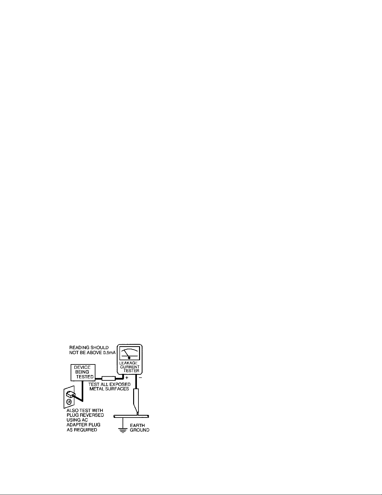
LEAKAGE CURRENT HOT CHECK
1. Do not use an isolation transformer for this test. Plug the completely reassembled
receiver directly into the ac outlet.
2. Connect a 1.5k, 1OW resistor paralleled by a 0.15uF. capacitor between each
exposed metallic cabinet part and a good earth ground such as a water pipe, as shown
below.
3. Use an ac voltmeter with at least 5000 ohms/volt sensitivity to measure the potential
across the resistor.
4. The potential at any point should not exceed 0.75 volts. A leakage current tester may
be used to make this test; leakage current must not exceed 0.5milliamp. If a
measurement is outside of the specified limits, there is a possibility of shock hazard. The
receiver should be repaired and rechecked before returning it to the customer.
5. Repeat the above procedure with the ac plug reversed. (Note: An ac adapter is
necessary when a polarized plug is used. Do not defeat the polarizing feature of the
plug.)
OR
With the instrument completely reassembled, plug the AC line cord directly into a 120V
AC outlet. (Do not use an isolation transformer during this test.) Use a leakage
current tester or a metering system that complies with American National Standards
Institute (ANSI) C101.1 Leakage Current for Appliances and Underwriters Laboratories
(UL) 1410, (50.7). With the instrument AC switch first in the on position and then
in the off position, measure from a known earth ground (metal water pipe, conduit,
etc.) to all exposed metal parts of the instrument (antennas, handle brackets, metal
cabinet, screw heads, metallic overlays, control shafts, etc.), especially any exposed
metal parts that offer an electrical return path to the chassis. Any current
measured must not exceed 0.5 milliamp. Reverse the instrument power cord plug in
the outlet and repeat the test. See graphic below.

PICTURE TUBE REPLACEMENT
The primary source of X-radiation in this television receiver is the picture tube. The
picture tube utilized in this chassis is specially constructed to limit X-radiation emissions.
For continued X-radiation protection, the replacement tube must be the same type as the
original, including suffix letter, or a Philips approved type.
PARTS REPLACEMENT
Many electrical and mechanical parts in Philips television sets have special safety related
characteristics. These characteristics are often not evident from visual inspection nor can
the protection afforded by them necessarily be obtained by using replacement
components rated for higher voltage, wattage, etc. The use of a substitute part which
does not have the same safety characteristics as the Philips recommended replacement
part shown in this service manual may create shock, fire, or other hazards

Chassis Identification and Interchangability
Chassis Identification
An identification label is located on the outside of the cabinet back. The first four characters (25R5)
indicate the basic chassis series. The next two numbers (01) identify the total Electronic Package in the
Cabinet. The last two letters (AA) are used to identify production changes that do not affect the basic
function of the chassis versions. Minor changes may not be identified within the letters, however, they will
be called out on the schematic as Early Production (E.P.) and Late Production (L.P.) changes. When
ordering parts or requesting technical assistance or information, the complete chassis number must be
supplied (e.g., 25R501 -OOAA).
INTERCHANGEABILITY NOTICE
Important: While the following holds true in most cases, always refer to the most up-to-date service
information for confirmation of interchangeability. The 8 digit Base No. identifies a family of assemblies.
The remaining 4 characters (called the Group No.) indicate the type of interchangeability within the family.
Example: Base No. Group No.
00APP012 A001
Note: Families having different Base No's. cannot be interchanged.
The ninth digit (first digit of the Group No.) identifies the group interchangeability level. This will be an
alpha character. Higher groups may replace lower groups, but lower groups cannot be substituted for
higher groups.
Example: 00APP012 A001
00APP012 B002
00APP012 C003
00APP012 B002 can be replaced by a C003 but not by an A001. In addition, a C003 can be used in place
of either a B002 or an A001.
The last two digits of the identification number indicate running changes. When a particular identification
number is initially assigned, it will be A001. Any change which does not significantly change the
operational characteristics or the external wiring configuration is a running change within the group. This
allows bidirectional interchangeability within the group. Example: A001 can be used in place of A003, and
A003 can be used in place of A001.
However, if a significant change does occur which will only allow higher revision substitution, the group
identifier (9th position character) must change.
Example: 00APP012 A001 (Early Production)
00APP012 A002
00APP012 A003
00APP012 B004
00APP012 B005
00APP012 B006 (Late Production
00APP012 A001 is the initial identification number. all assemblies in the "A" group (9th position character)
are interchangeable with each other. All of the assemblies in the "B" group are interchangeable with each
other, and any "B" group assembly can be substituted for an "A" group. However, an "A" group assembly
cannot be substituted for a "B" group assembly.
Chassis Breakdown List
NOTE: THE LOCATION OF INFORMATION IN THE MANUAL IS INDICATED BY BOTH PAGE NUMBER
AND MICROFICHE FRAME NUMBER. PAPER MANUAL USERS SHOULD REFER ONLY TO THE
PAGE NUMBERS. MICROFICHE MANUAL USERS SHOULD REFER ONLY TO THE FRAME
NUMBERS.
CHASSIS BREAKDOWN NOTES:
1. ITEMS SHOWN INDENTED IN THE PARTS LIST BELOW ARE SUB-ASSEMBLY TYPE ITEMS TO
THE ITEM SHOWN ABOVE IT.
# INDICATES A "NON-REPLACEABLE/REPAIR ONLY TYPE OF ASSEMBLY.
R5 CHASSIS BREAKDOWN LIST

20R501
00APT145 CRT Module
# 00EMR590 Main Chassis
00ALR016 IR Assembly
00AVJ177 Jack Panel
003403130005 Varactor Tuner
Typical Model: PA5020C1
25R501
00APT146 CRT Module
# 00EMR525 Main Chassis
00ALR016 IR Assembly
00ASW116 Keyboard
003403130005 Varactor Tuner
Typical Model: 25T222
25R502
00APT146 CRT Module
# 00EMR535 Main Chassis
00ALR016 IR Assembly
00ASW116 Keyboard
003403130005 Varactor Tuner
Typical Model: TP2526
25R503
00APT146 CRT Module
# 00EMR515 Main Chassis
00ALR016 IR Assembly
00ASW116 Keyboard
003403130005 Varactor Tuner
Typical Model:TS2552
25R504
00APT146 CRT Module
# 00EMR545 Main Chassis
00ALR016 IR Assembly
00ASW116 Keyboard
003403130005 Varactor Tuner
Typical Model: CT2526
25R505
00APT146 CRT Module
# 00EMR555 Main Chassis
00ALR016 IR Assembly
00ASW116 Keyboard
003403130005 Varactor Tuner
Typical Model: TS2582C1
27R501
00APT146 CRT Module
# 00EMR587 Main Chassis
00ALR016 IR Assembly
00ASW116 Keyboard
003403130005 Varactor Tuner
Typical Model: CT2747
27R502
00APT146 CRT Module
# 00EMR537 Main Chassis
00ALR016 IR Assembly
00ASW116 Keyboard
003403130005 Varactor Tuner
Typical Model: CT2743C101
27R503
00APT146 CRT Module
# 00EMR557 Main Chassis
00ALR016 IR Assembly
00ASW116 Keyboard
003403130005 Varactor Tuner

Typical Model: HD2716
27R504
00APT146 CRT Module
# 00EMR507 Main Chassis
00ALR016 IR Assembly
00ASW116 Keyboard
003403130005 Varactor Tuner
Typical Model: CC2762
27R505
00APT146 CRT Module
# 00EMR597 Main Chassis
00ALR016 IR Assembly
00AVJ177 PRO Video Jack Panel
00ASW116 Keyboard
00AWR006 Diode Modulator 36
003403130005 Varactor Tuner
Typical Model: PA5027
27R506
00APT146 CRT Module
# 00EMR543 Main Chassis
00ALR016 IR Assembly
00ASW116 Keyboard
003403130005 Varactor Tuner
Typical Model: LS2940
27R507
00APT146 CRT Module
# 00EMR563 Main Chassis
00ALR016 IR Assembly
00ASW116 Keyboard
003403130005 Varactor Tuner
Typical Model: LS2961
27R508
00APT146 CRT Module
# 00EMR573 Main Chassis
00ALR016 IR Assembly
00ASW116 Keyboard
003403130005 Varactor Tuner
Typical Model: 27TP82
27R509
00APT146 CRT Module
# 00EMR583 Main Chassis
00ASW116 Keyboard
00ALR016 IR Assembly
003403130005 Varactor Tuner
Typical Model: LP2970C1
27R510
00APT146 CRT Module
# 00EMR547 Main Chassis
00ALR016 IR Assembly
00ASW116 Keyboard
003403130005 Varactor Tuner
Typical Model: CC2772
27R511
00APT146 CRT Module
# 00EMR553 Main Chassis
00ALR016 IR Assembly
00ASW116 Keyboard
003403130005 Varactor Tuner
Typical Model: LS2960
27R512
00APT146 CRT Module

# 00EMR586 Main Chassis
00ALR016 IR Assembly
00ASW116 Keyboard
003403130005 Varactor Tuner N /A
Typical Model: TP2782C1
27R513
00APT146 CRT Module
# 00EMR577 Main Chassis
00ASW116 Keyboard
00ALR016 IR Assembly
003403130005 Varactor Tuner
Typical Model: FS2770B1
32R502
00APT146 CRT Module
# 00EMR562 Main Chassis
00ALR016 IR Assembly
00ASW116 Keyboard
00AWR007 Diode Modulator 36
003403130005 Varactor Tuner
Typical Model: TP3287C1
32R503
00APT146 CRT Module
# 00EMR532 Main Chassis
00ALR016 IR Assembly
00ASW116 Keyboard
00AWR007 Diode Modulator 36
003403130005 Varactor Tuner
Typical Model: TS3262C1
32R504
00APT146 CRT Module
# 00EMR542 Main Chassis
00ALR016 IR Assembly
00ASW116 Keyboard
00AWR007 Diode Modulator 36
003403130005 Varactor Tuner
Typical Model: FS3262
32R505
00APT146 CRT Module
# 00EMR592 Main Chassis
00ALR016 IR Assembly
00ASW116 Keyboard
00AVJ177 Jack Panel 35
00AWR007 Diode Modulator 36
003403130005 Varactor Tuner
Typical Model: PA5032C1
32R506
00APT146 CRT Module
# 00EMR582 Main Chassis
00ALR016 IR Assembly
00ASW116 Keyboard
00AWR007 Diode Modulator 36
003403130005 Varactor Tuner
Typical Model: FP3272A1
32R507
00APT146 CRT Module
# 00EMR512 Main Chassis
00ALR016 IR Assembly
00ASW116 Keyboard
00AWR007 Diode Modulator 36
003403130005 Varactor Tuner
Typical Model: FS3270
20R501

00APT145 CRT Module
# 00EMR590 Main Chassis
00ALR016 IR Assembly
00AVJ177 Jack Panel
003403130005 Varactor Tuner
Typical Model: PA5020C1
25R501
00APT146 CRT Module
# 00EMR525 Main Chassis
00ALR016 IR Assembly
00ASW116 Keyboard
003403130005 Varactor Tuner
Typical Model: 25T222
25R502
00APT146 CRT Module
# 00EMR535 Main Chassis
00ALR016 IR Assembly
00ASW116 Keyboard
003403130005 Varactor Tuner
Typical Model: TP2526
25R503
00APT146 CRT Module
# 00EMR515 Main Chassis
00ALR016 IR Assembly
00ASW116 Keyboard
003403130005 Varactor Tuner
Typical Model:TS2552
25R504
00APT146 CRT Module
# 00EMR545 Main Chassis
00ALR016 IR Assembly
00ASW116 Keyboard
003403130005 Varactor Tuner
Typical Model: CT2526
25R505
00APT146 CRT Module
# 00EMR555 Main Chassis
00ALR016 IR Assembly
00ASW116 Keyboard
003403130005 Varactor Tuner
Typical Model: TS2582C1
27R501
00APT146 CRT Module
# 00EMR587 Main Chassis
00ALR016 IR Assembly
00ASW116 Keyboard
003403130005 Varactor Tuner
Typical Model: CT2747
27R502
00APT146 CRT Module
# 00EMR537 Main Chassis
00ALR016 IR Assembly
00ASW116 Keyboard
003403130005 Varactor Tuner
Typical Model: CT2743C101
27R503
00APT146 CRT Module
# 00EMR557 Main Chassis
00ALR016 IR Assembly
00ASW116 Keyboard
003403130005 Varactor Tuner
Typical Model: HD2716

27R504
00APT146 CRT Module
# 00EMR507 Main Chassis
00ALR016 IR Assembly
00ASW116 Keyboard
003403130005 Varactor Tuner
Typical Model: CC2762
27R505
00APT146 CRT Module
# 00EMR597 Main Chassis
00ALR016 IR Assembly
00AVJ177 PRO Video Jack Panel
00ASW116 Keyboard
00AWR006 Diode Modulator 36
003403130005 Varactor Tuner
Typical Model: PA5027
27R506
00APT146 CRT Module
# 00EMR543 Main Chassis
00ALR016 IR Assembly
00ASW116 Keyboard
003403130005 Varactor Tuner
Typical Model: LS2940
27R507
00APT146 CRT Module
# 00EMR563 Main Chassis
00ALR016 IR Assembly
00ASW116 Keyboard
003403130005 Varactor Tuner
Typical Model: LS2961
27R508
00APT146 CRT Module
# 00EMR573 Main Chassis
00ALR016 IR Assembly
00ASW116 Keyboard
003403130005 Varactor Tuner
Typical Model: 27TP82
27R509
00APT146 CRT Module
# 00EMR583 Main Chassis
00ASW116 Keyboard
00ALR016 IR Assembly
003403130005 Varactor Tuner
Typical Model: LP2970C1
27R510
00APT146 CRT Module
# 00EMR547 Main Chassis
00ALR016 IR Assembly
00ASW116 Keyboard
003403130005 Varactor Tuner
Typical Model: CC2772
27R511
00APT146 CRT Module
# 00EMR553 Main Chassis
00ALR016 IR Assembly
00ASW116 Keyboard
003403130005 Varactor Tuner
Typical Model: LS2960
27R512
00APT146 CRT Module
# 00EMR586 Main Chassis

00ALR016 IR Assembly
00ASW116 Keyboard
003403130005 Varactor Tuner N /A
Typical Model: TP2782C1
27R513
00APT146 CRT Module
# 00EMR577 Main Chassis
00ASW116 Keyboard
00ALR016 IR Assembly
003403130005 Varactor Tuner
Typical Model: FS2770B1
32R502
00APT146 CRT Module
# 00EMR562 Main Chassis
00ALR016 IR Assembly
00ASW116 Keyboard
00AWR007 Diode Modulator 36
003403130005 Varactor Tuner
Typical Model: TP3287C1
32R503
00APT146 CRT Module
# 00EMR532 Main Chassis
00ALR016 IR Assembly
00ASW116 Keyboard
00AWR007 Diode Modulator 36
003403130005 Varactor Tuner
Typical Model: TS3262C1
32R504
00APT146 CRT Module
# 00EMR542 Main Chassis
00ALR016 IR Assembly
00ASW116 Keyboard
00AWR007 Diode Modulator 36
003403130005 Varactor Tuner
Typical Model: FS3262
32R505
00APT146 CRT Module
# 00EMR592 Main Chassis
00ALR016 IR Assembly
00ASW116 Keyboard
00AVJ177 Jack Panel 35
00AWR007 Diode Modulator 36
003403130005 Varactor Tuner
Typical Model: PA5032C1
32R506
00APT146 CRT Module
# 00EMR582 Main Chassis
00ALR016 IR Assembly
00ASW116 Keyboard
00AWR007 Diode Modulator 36
003403130005 Varactor Tuner
Typical Model: FP3272A1
32R507
00APT146 CRT Module
# 00EMR512 Main Chassis
00ALR016 IR Assembly
00ASW116 Keyboard
00AWR007 Diode Modulator 36
003403130005 Varactor Tuner
Typical Model: FS3270

Model to Chassis List
MODELS SCREEN CHASSIS
SIZE
CROSLEY
CT2526C102 25" 25R504
CC2762A101 27" 27R504
CC2772A101 27" 27R510
CT2743C101 27" 27R502
CT2747C101 27" 27R501
CT2747C102 27" 27R512
CC3262A101 32" 32R504
CT3212C101 32" 32R503
MAGNAVOX
25TS52C203 25" 25R503
25TS72C101 25" 25R503
TP2592B102 25" 25R501
TS2572C103 25" 25R504
TP2526C102 25" 25R502
TS2582C102 25" 25R505
TS2552C203 25" 25R503
FS2762A101 27" 27R504
FP2772A101 27" 27R510
FP2774B101 27" 27R510
FS2770B101 27" 27R513
HD2716C101 27" 27R503
27TP82C101 27" 27R501
27TP82C102 27" 27R512
27TS73C101 27" 27R502
TP2782C101 27" 27R501
TP2782C102 27" 27R512
TS2773C101 27" 27R502
XS2773C101 (Canada) 27" 27R502
FP3272A101 32" 32R506
FP3274B101 32" 32R506
FS3262A101 32" 32R504
FS3270B101 32" 32R507
XS3272C101 (Canada) 32" 32R503
TP3287C101 32" 32R502
TP3262C101 32" 32R503
TS3262C101 32" 32R503
TS3272C101 32" 32R502
PHILIPS
PA5020C101 20" 20R501
27T502C101 27" 27R501
27T502C102 27" 27R512
LP2970C101 (Latin) 29" 27R509
LP2971C101 (Latin) 29" 27R508
LS2940C101 (Latin) 29" 27R506
LS2960C101 (Latin) 29" 27R511
LS2961C101 (Latin) 29" 27R507
PA5027C101 (Latin) 27" 27R505
PA5032C101 32" 32R505
REPLACEMENT PANEL LIST
# INDICATES A "NON-REPLACEABLE/REPAIR ONLY" TYPE OF ASSEMBLY
00ALR000 A001 Remote Receiver Module 4835 219 57541
00APT146 A001 CRT Module 4835 219 57544
00ASW116 A001 Keyboard Module 4835 219 57545
00AVJ177 A001 Jack Panel 4835 219 57551
00AWR006 A001 Diode Modulator 4835 219 57553
00AWR007 A001 Diode Modulator 4835 219 57538

00EMR507 A002 Main Chassis 4835 219 28234
00EMR512 A002 Main Chassis 4835 219 28235
00EMR515 A002 Main Chassis 4835 219 28228
00EMR525 A002 Main Chassis 4835 219 28236
00EMR532 A002 Main Chassis 4835 219 28237
00EMR535 A002 Main Chassis 4835 219 28238
00EMR537 A002 Main Chassis 4835 219 28239
00EMR542 A002 Main Chassis 4835 219 28241
00EMR543 A002 Main Chassis 4835 219 28242
00EMR545 A002 Main Chassis 4835 219 28243
# 00EMR547 A002 Main Chassis 4835 219 28244
# 00EMR553 A002 Main Chassis 4835 219 28245
# 00EMR555 A002 Main Chassis 4835 219 28246
# 00EMR557 A002 Main Chassis 4835 219 28247
# 00EMR562 A002 Main Chassis 4835 219 28248
# 00EMR563 A002 Main Chassis 4835 219 28249
# 00EMR573 A002 Main Chassis 4835 219 28251
# 00EMR577 A002 Main Chassis 4835 219 28252
# 00EMR582 A002 Main Chassis 4835 219 28253
# 00EMR583 A002 Main Chassis 4835 219 28254
# 00EMR586 A002 Main Chassis 4835 219 28255
# 00EMR587 A002 Main Chassis 4835 219 28256
# 00EMR590 A002 Main Chassis 4835 219 28257
# 00EMR592 A002 Main Chassis 4835 219 28258
# 00EMR597 A002 Main Chassis 4835 219 28259
REMOTE TRANSMITTER REPLACEMENT LIST
Description Part Number
H145DA BA02 4835 219 17599
M145DA BA02 4835 219 17609
M145DB BA02 4835 219 17591
H175CD BA02 4835 219 17604
M175CB BA02 4835 219 17606
M175CD BA02 4835 219 17607
M175DA BA02 4835 219 17608
M175DB BA02 4835 219 17592
T225AG MA02 4835 219 17582
Battery Doors for Remote Transmitters:
H175CD,M175CB,M175CD,M175DA,M175DB 4835 432 37084
H145DA, M145DB, M145DA 4835 432 37081
T225AG 4835 432 37085
REMOTE TRANSMITTER BATTERY DOORS
P/N(Batt Door) REMOTE
4835 432 37081 G145DA BA02, G145DB BA02,
4835 432 37081 H145DB BA02, M145DA BA02,
4835 432 37081 M145DB BA02
4835 432 37084 H175DA BA02, H175DB BA02,
4835 432 37084 H175DD BA02, M175DA BA02,
4835 432 37084 M175DB BA02
4835 432 37085 T214AG GA03, T225AG MA02
4835 432 37085 T225AG PH02
REMOTE TRANSMITTER TO MODEL LIST
BELL & HOWELL
G145DA BA02 GNB128
G145DB BA02 GNB127, 128
CROSLEY

G145DA BA02 CT2526, CC2762, CT2743, CC3262, CT3212
G145DB BA02 CC2772, CC2744, CT2747
PHILIPS
T214AG GA03 PA5020, PA5027, PA5032
T225AG PH02 LS2940
H175DA BA02 25PS82, LS2961
H175DB BA02 27T502
H175DD BA02 LP2970, LP2971
MAGNAVOX
M145DA BA02 25TS72, TS2572, FS2762, FS2770, 27TS73, FS3262, XS3272, TS3272
M145DB BA02 TP2526, FP2772, FP2774, FP3272
M175DA BA02 TS2582
M175DB BA02 TP2592, 27TP82, TP2782, TP3287
T225AG MA02 25TS52, TS2552, HD2716, XS2773
Model Replacement Parts List
MODEL REPLACEMENT PARTS LISTS
NOTE: THE "S" IN THE LEFT COLUMN INDICATES THE PART IS A
CRITICAL SAFETY COMPONENT AND SHOULD BE REPLACED ONLY
WITH THE PHILIPS PART NUMBER.
BELL & HOWELL
GNB1271106,1107, 1108 27"
S 4835 321 17079 AC Cord
4835 432 97579 Back
4835 410 37244 Button Asm.
4835 256 97264 Clip, Anode Lead
4835 450 67214 Crystal
S 4835 131 27123 CRT A68AGN32X (1106. 1108)
S 4835 131 27134 CRT A68AGN32X02 (1107)
S 4835 150 27008 Convergence & Purity Asm. (1106, 1108)
S 4835 150 17098 Deflection Yoke (1106,1108)
4835 535 27006 Yoke Wedges (3 used)
S 4835 157 97058 Degaussing Coil
4835 256 97265 Degaussing Coil Holder
4835 430 67134 Front
4835 459 17532 Nameplate
4835 459 17524 Overlay
4835 240 37022 Speaker 3" (2 used)
4835 138 17047 Battery f/Transmitter (1.5V)
001B 734 5E001 Owner's Manual
GNB1281102,1104 32"
S 4835 321 17079 AC Cord
4835 432 97599 Back
4835 410 37246 Buttons
4835 256 97264 Clip, Anode Lead
4835 450 67211 Crystal
S 4835 131 27106 CRT A80EFF272X53 (1102, 1104)
S 4835 157 97052 Degaussing Coil
4835 256 97265 Degaussing Coil Holder
4835 450 67200 Lens, IR
4835 459 17532 Nameplate
4835 459 17519 Overlay

4835 240 27007 Speaker 2.25X5" (2 used)
4835 138 17047 Battery f/Transmitter (1.5V)
001B 734 4E001 Owner's Manual
GNB12911029 1103 32"
S 4835 321 17079 AC Cord
4835 432 97599 Back
4835 410 37237 Buttons
4835 256 97264 Clip, Anode Lead
S 4835 131 27106 CRT A80EFF272X53
S 4835 157 97052 Degaussing Coil
4835 256 97265 Degaussing Coil Holder
4835 430 67133 Front
4835 450 67200 Lens, IR
4835 459 17532 Nameplate
4835 459 17524 Overlay
4835 240 27017 Speaker 2.25X5" (2 used)
4835 138 17047 Battery f/Transmitter (1.5V)
001B 734 3EO01 Owner's Manual
CROSLEY
CT2526C101,C102 25"
S 4835 321 17079 AC Cord
4835 432 97505 Back
4835 410 97024 Buttons
4835 256 97264 Clip, Anode Lead
4835 450 67203 Crystal
S 4835 131 27091 CRT A63AFW42X (C101)
S 4835 131 27127 CRT A63AFW36X (C102)
S 4835 150 27008 Convergence & Purity Asm.
S 4835 150 17116 Deflection Yoke
4835 535 27006 Yoke Wedges (3 used)
S 4835 157 97077 Degaussing Coil
4835 256 97265 Degaussing Coil Holder
4835 430 57165 Front
4835 450 67202 Lens,IR
4835 459 17522 Nameplate
4835 459 17519 Overlay, Jack Panel
4835 432 17748 Jack Panel (Plastic)
4835 240 37002 Speaker 3" (2 used)
4835 138 17047 Battery f/Transmitter (1.5V)
001B 7203EO01 Owner's Manual
001B 7203F001 Owner's Manual
C2762A101,A102,A103 27"
S 4835 321 17079 AC Cord
4835 432 97582 Back
4835 410 97027 Buttons
4835 256 97264 Clip, Anode Lead
4835 450 67218 Crystal
S 4835 131 27123 CRT A68AGN32X (A101, A103)
S 4835 131 27134 CRT A68AGN32XO2 (A102)
S 4835 150 27008 Convergence & Purity Asm. (A101, A103)
S 4835 150 17098 Deflection Yoke (A101, A103)
4835 535 27006 Yoke Wedges (3 used)
S 4835 157 97058 Degaussing Coil
4835 256 97265 Degaussing Coil Holder
4835 432 67216 Front Grille Asm.
4835 450 67202 Lens, IR
4835 459 17516 Nameplate

4835 459 17524 Overlay
4835 240 37024 Speaker 3X5" (2 used)
4835 138 17047 Battery f[Transmitter (1.5V)
001B 722 6E001 Owner's Manual
001B 722 6E001 Owner's Manual
CC2772A101,A102,A103 27"
S 4835 321 17079 AC Cord
4835 432 97582 Back
4835 410 97027 Buttons
4835 256 97264 Clip, Anode Lead
4835 450 67218 Crystal
S 4835 131 27123 CRT A68AGN32X(A101,A103)
S 4835 131 27134 CRT A68AGN32XO2 (A102)
S 4835 150 27008 Convergence & Purity Asm. (A101, A103)
S 4835 150 17098 Deflection Yoke (A101, A103)
4835 535 27006 Yoke Wedges (3 used)
S 4835 157 97058 Degaussing Coil
4835 256 97265 Degaussing Coil Holder
4835 432 67216 Front Grille Asm.
4835 450 67202 Lens, IR
4835 459 17516 Nameplate
4835 459 17524 Overlay
4835 240 37024 Speaker 3X5" (2 used)
4835 138 17047 Battery f/Transmitter (1.5V)
001B 724 6E001 Owner's Manual
001B 724 6F0Ol Owner's Manual
CC2774B101, B102, B103 27"
S 4835 321 17079 AC Cord
4835 432 97582 Back
4835 410 97027 Buttons
4835 256 97264 Clip, Anode Lead
4835 450 67218 Crystal
S 4835 131 27123 CRT A68AGN32X (B101, B103)
S 4835 131 27134 CRT A68AGN32XO2 (B102)
S 4835 150 27008 Convergence & Purity Asm. (B101, B103)
S 4835 150 17098 Deflection Yoke (B101, B103)
4835 535 27006 Yoke Wedges (3 used)
S 4835 157 97058 Degaussing Coil
4835 256 97265 Degaussing Coil Holder
4835 432 67216 Front Grille Asm.
4835 459 17516 Nameplate
4835 459 17524 Overlay
4835 240 37024 Speaker 3X5 (2 used)
4835 138 17047 Battery fiTransmitter (1.5V)
001B 724 6E001 Owner's Manual
001B 724 6F001 Owner's Manual
CT2743C101,C102,C103,C104 27"
S 4835 321 17079 AC Cord
4835 432 97579 Back
4835 432 17667 Buttons
4835 256 97264 Clip, Anode Lead
4835 450 67213 Crystal
S 4835 131 27119 CRT A68KR088X(D) (C102)
S 4835 131 27123 CRT A68AGN32X (C101, C104)
S 4835 131 27134 CRT A68AGN32XO2 (C103)
S 4835 150 27008 Converg. & Purity Asm. (C101, C102, C104)
S 4835 150 17103 Deflection Yoke (C102)
S 4835 150 17098 Deflection Yoke (C101, C104)

4835 535 27006 Yoke Wedges (3 used) C101, C102, C104
S 4835 157 97058 Degaussing Coil
4835 256 97265 Degaussing Coil Holder
4835 430 67141 Front (C101, C103, C104)
4835 430 67142 Front (C102)
4835 450 67202 Lens, IR
4835 459 17522 Nameplate
4835 459 17519 Overlay, Jack Panel
4835 240 27007 Speaker 2.25X5 (2 used)
4835 138 17047 Battery f/Transmitter (1.5V)
001B 7223E001 Owner's Manual
001B 7223F001 Owner's Manual
CT2747C101,C103,C104 27"
S 4835 321 17079 AC Cord
S 4835 432 97579 Back
S 4835 410 37244 Button Asm.
S 4835 256 97264 Clip, Anode Lead
4835 450 67214 Crystal
S 4835 131 27123 CRT A68AGN32X (C101, C104)
S 4835 131 27134 CRT A68AGN32XO2 (C103)
S 4835 150 27008 Converg. & Purity Asm. (C101, C104)
S 4835 150 17098 Deflection Yoke (C101, C104)
4835 535 27006 Yoke Wedges (3 used) (C101, C104)
S 4835 157 97058 Degaussing Coil
4835 256 97265 Degaussing Coil Holder
4835 430 67134 Front
4835 459 17522 Nameplate
4835 459 17524 Overlay
4835 240 37022 Speaker 2.25X5 (2 used)
4835 138 17047 Battery f/Transmitter (1.5V)
001B 721 9E001 Owner's Manual
001B 721 9E001 Owner's Manual
CC3262A101, A103 32"
S 4835 321 17079 AC Cord
4835 432 97583 Back
4835 410 97027 Buttons
4835 256 97264 Clip, Anode Lead
4835 450 67218 Crystal
S 4835 131 27106 CRT A80EFF272X53(A101,A103)
S 4835 157 97052 Degaussing Coil
4835 256 97265 Degaussing Coil Holder
4835 432 67214 Front Grille Asm.
4835 450 67202 Lens, IR
4835 459 17516 Nameplate
4835 459 17524 Overlay
4835 240 37024 Speaker 3X5 (2 used)
4835 138 17047 Battery f/Transmitter (1.5V)
001B 722 6E001 Owner's Manual
001B 722 6F001 Owner's Manual
CT3212C101,C103 32"
S 4835 321 17079 AC Cord
4835 432 97578 Back
4835 410 37246 Buttons
4835 256 97264 Clip, Anode Lead
4835 450 67218 Crystal
S 4835 131 27106 CRT ABOEFF272X53 (C101, C103)
S 4835 157 97052 Degaussing Coil
4835 256 97265 Degaussing Coil Holder

4835 430 67122 Front
4835 450 67200 Lens, IR
4835 459 17522 Nameplate
4835 459 17519 Overlay, Jack Panel
4835 240 27007 Speaker 2.25X5" (2 used)
4835 138 17047 Battery f/Transmitter (1.5V)
001B 721 8E001 Owner's Manual
001B 721 8F001 Owner's Manual
MAGNAVOX
25TS52C202,C203 25"
S 4835 321 17079 AC Cord
4835 432 97505 Back
4835 410 97024 Buttons
4835 256 97264 Clip, Anode Lead
4835 450 67203 Crystal
S 4835 131 27091 CRT A63AFW42X (C202)
S 4835 131 27127 CRT A63AFW36X (C203)
S 4835 150 27008 Convergence & Purity Asm.
S 4835 150 17116 Deflection Yoke
4835 535 27006 Yoke Wedges (3 used)
S 4835 157 97077 Degaussing Coil
4835 256 97265 Degaussing Coil Holder
4835 430 57165 Front
4835 459 17517 Nameplate
4835 459 17518 Overlay
4835 432 17748 Jack Panel (Plastic)
4835 240 37002 Speaker 3" (2 used)
4835 138 17001 Battery f/Transmitter (AAA)
001B 730 2E001 Owner's Manual
25TS72C101,C103 25"
S 4835 321 17079 AC Cord
4835 432 97505 Back
4835 410 97024 Buttons
4835 256 97264 Clip, Anode Lead
4835 450 67203 Crystal
S 4835 131 27091 CRT A63AFW42X (C101)
S 4835 131 27127 CRT A63AFW36X (C103)
S 4835 150 27008 Convergence & Purity Asm.
S 4835 150 17116 Deflection Yoke
S 4835 535 27006 Yoke Wedges (3 used)
S 4835 157 97077 Degaussing Coil
4835 256 97265 Degaussing Coil Holder
4835 430 57165 Front
4835 459 17517 Nameplate
4835 459 17518 Overlay
4835 432 17748 Jack Panel (Plastic)
4835 240 37002 Speaker 3" (2 used)
4835 138 17047 Battery f/Transmifter (1.5V)
001B 721 4E001 Owner's Manual
TS2572C101,C103 25"
S 4835 321 17079 AC Cord
S 4835 432 97505 Back
S 4835 410 37233 Button Asm.
S 4835 256 97264 Clip, Anode Lead
S 4835 450 67205 Crystal
S 4835 131 27091 CRT A63AFW42X (C101)

S 4835 131 27127 CRT A63AFW36X (C103)
S 4835 150 27008 Convergence & Purity Asm.
S 4835 150 17116 Deflection Yoke
4835 535 27006 Yoke Wedges (3 used)
S 4835 157 97077 Degaussing Coil
4835 256 97265 Degaussing Coil Holder
4835 430 57163 Front
4835 459 17517 Nameplate
4835 459 17519 Overlay
4835 432 17748 Jack Panel (Plastic)
4835 240 37002 Speaker 3" (2 used)
4835 138 17047 Battery f[Transmifter (1.5V)
001B 721 3E001 Owner's Manual
TP2592B101, B102 25"
S 4835 321 17079 AC Cord
4835 432 97505 Back
4835 410 37233 Button Asm.
4835 256 97264 Clip, Anode Lead
4835 450 67205 Crystal
S 4835 131 27091 CRT A63AFW42X (B101)
S 4835 131 27127 CRT A63AFW36X (B102)
S 4835 150 27008 Convergence & Purity Asm.
S 4835 150 17116 Deflection Yoke
4835 535 27006 Yoke Wedges (3 used)
S 4835 157 97077 Degaussing Coil
4835 256 97265 Degaussing Coil Holder
4835 430 57174 Front
4835 459 17534 Nameplate
4835 459 17524 Overlay
4835 432 17748 Jack Panel (Plastic)
4835 240 37022 Speaker 3" (2 used)
4835 138 17012 Battery f/Transmitter (AA)
001B 720 8E001 Owner's Manual
TP2526,C101, C102 25"
S 4835 321 17079 AC Cord
S 4835 432 97505 Back
S 4835 410 97024 Buttons
4835 256 97264 Clip, Anode Lead
4835 450 67203 Crystal
S 4835 131 27091 CRT A63AFW42X (C101)
S 4835 131 27127 CRT A63AFW36X (C102)
S 4835 150 27008 Convergence & Purity Asm.
S 4835 150 17116 Deflection Yoke
4835 535 27006 Yoke Wedges (3 used)
S 4835 157 97077 Degaussing Coil
4835 256 97265 Degaussing Coil Holder
4835 430 57165 Front
4835 450 67202 Lens, IR
4835 459 17517 Nameplate
4835 459 17523 Overlay, Jack Panel
4835 432 17748 Jack Panel (Plastic)
4835 240 37002 Speaker 3" (2 used)
4835 138 17047 Battery f/Transmitter (1.5V)
001B 721 1E001 Owner's Manual
TS2552C202,C203 25"
S 4835 321 17079 AC Cord
S 4835 432 97505 Back
 Loading...