

Page 1
3121 233 43531
Quick Use and Hookup Guide
Important Notice/Warning . . . . . . . . . . . . . . . . . . . . .1
Basic TV Operation . . . . . . . . . . . . . . . . . . . . . . . . . .1
Remote Battery Installation . . . . . . . . . . . . . . . . . . .1
Remote Control Button Descriptions . . . . . . . . . . . .1
Hooking Up the TV
Basic Cable TV Connections . . . . . . . . . . . . . . . . . .2
Basic Cable Box Connections . . . . . . . . . . . . . . . . .2
Basic Antenna TV Connections . . . . . . . . . . . . . . . .2
Using the AV1 Inputs . . . . . . . . . . . . . . . . . . . . . . . .3
Using the AV2 Inputs . . . . . . . . . . . . . . . . . . . . . . . .3
Using the Component Video Inputs . . . . . . . . . . . . .3
Using the S-Video Inputs . . . . . . . . . . . . . . . . . . . . .4
Using the Monitor (Audio/Video) Outputs . . . . . . .4
Using the Side Audio/Video Inputs . . . . . . . . . . . . .4
IMPORTANT
NOTE: This owner's manual is used with several
different television models. Not all features (and
drawings) discussed in this manual will necessarily match those found with your television set.
This is normal and does not require that you contact your dealer or request service.
WARNING: TO PREVENT FIRE OR SHOCK
HAZARD DO NOT EXPOSE THIS UNIT TO
RAIN OR EXCESSIVE MOISTURE.
Color TV
Color TV
CONTENTS
BASIC TV AND REMOTE OPERATION
Y
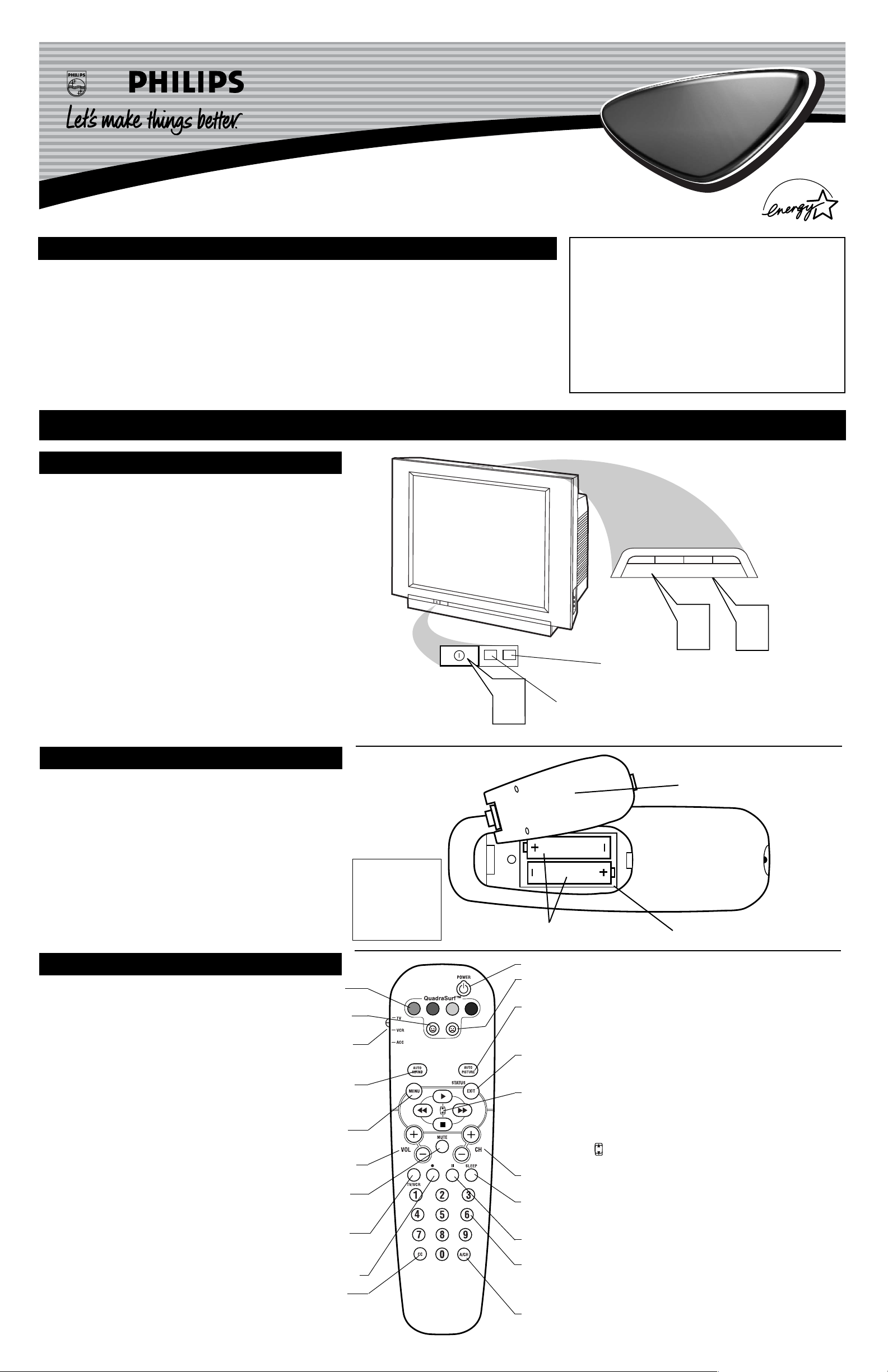
our television has a set of controls located on the font of
the cabinet for use when the remote control is not needed.
1
Press the POWER button to turn the TV ON.
2
Press the VOL (+) button to increase the sound level or
the VOL (–) button to lower the sound level.
Pressing both buttons at the same time will display the
onscreen menu. After you are in the menu, use these buttons
to make adjustments or selections.
3
Press the CH – (down) or + (up) button to select TV channels. Use these buttons to make adjustments or selections in
the onscreen menu.
There is also a set of Audio and Video Input jacks located on
the side of the television cabinet. This jack panel also contains a Svideo and headphone jack. These jacks are great for connecting a
video camcorder or any accessory device that will only be hooked
up temporarily.
TELEVISION
T
o load the supplied batteries into the remote:
1
Remove the battery compartment door on the back of
the remote.
2
Place the batteries (2-AA) in the remote. Be sure the (+)
and (–) ends of the batteries line up correctly (the inside of
the case is marked).
3
Reattach the battery compartment door.
REMOTE CONTROL BATTERIES
Remote Control
(shown from the bottom)
Battery Compartment Door
2 “AA” Batteries
Battery Compartment
Installing the Remote
Control Batteries
Be sure to point the
remote at the Remote
Sensor window on the
front of the television
when using the remote
control to operate the
television.
Remote Sensor - Sensor for activating
remote control commands when the
remote is used to control the TV.
Power Light Indicator - Light will
show while TV is powered on.
R
EMOTE
CONTROL
BUTTONS
QUADRA SURF Buttons - (Red, Green, Yellow, Blue) Allows you to
store and surf up to 10 channels you choose for each colored button.
SMILEY Button - Press to add channels in the “Quadra Surf” lists. Works
with all colored buttons.
TV/VCR/ACC MODE SWITCH - Slide to position of TV to control TV
functions, VCR to control VCR functions and ACC for Cable Converter, DBS,
DVD, etc., functions.
AUTO SOUND Button - Press repeatedly to choose from different factory
pre-defined sound settings. Choose from Personal (how you set the Sound Menu
options), Voice (for programming with speaking only), Music (for musical type
programs such as concerts), or Theatre (used when watching movies).
MENU Button - Press to display the onscreen menu. Also can be used to
back out of the onscreen menu until it disappears from the TV’s screen.
VOL(ume) + or – Buttons - Press the VOL + button to increase the TV’s
sound level. Press the VOL – button to decrease the TV’s sound level.
MUTE Button - Press the mute button to eliminate the sound being heard
from the TV. “MUTE” will be displayed on the TV’s screen. Press again to
restore the TV’s volume to it’s previous level.
TV/VCR Button - When in the VCR Mode, press to toggle between VCR
viewing and TV viewing. When in the TV mode, this button will have no
functionality.
•
(VCR Record) Button - Press to start a VCR recording of a TV program.
CC Button - Press to activate the Closed Captioning options. Repeatedly
press the CC button with scroll the options available on the TV screen.
POWER Button - Press the Power button to turn the TV on or off.
FROWNIE Button - Allows you to delete stored channels within the “Quadra
Surf” lists for the colored buttons.
AUTO PICTURE Button - Press repeatedly to choose from 4 different factory
pre-defined picture settings. Choose from Personal (how you set the Picture Menu
adjustment controls), Movies (when watching movies), Sports (for any sporting
event), or Weak Signal (used when the signal being received is not the best).
STATUS/EXIT Button - Press to display the current channel number. If the
onscreen menu is displayed, press the Status/Exit button will remove it from the
TV’s screen.
CURSOR, , , or Buttons - Press to navigate, select and adjust
controls within the onscreen menu after the Menu button is pressed. These buttons also can be used with a VCR and when the TV/VCR/ACC Switch is in the
VCR position. Press the to PLAY , REWIND , FAST FORWARD ,
or STOP ■ the viewing of a prerecorded video tape.
Also use the CURSOR
UP or DOWN to activate or deactivate the EXPAND 4:3 screen
formatting control.
CH(annel) + or – Buttons - Press to select channels in ascending or descend-
ing order.
SLEEP Button - Press the Sleep button to set the TV to automatically turn itself
off after a set period of time. Press repeatedly to select 15, 30, 45, 60, 90, 120, or
180 minutes.
II PAUSE Button - Press to pause the viewing of a prerecorded video. The pic-
ture will freeze on the screen until the Play or Pause buttons are pressed again.
NUMBERED (0-9) Buttons - Press the numbered buttons to select TV chan-
nels or to enter certain values within the onscreen menu. For single channel
entries, press the numbered button for the channel you desire. the TV will pause
for a second or two before changing to the chosen channel.
A/CH Button - (Alternate Channel) Press to toggle between the last view
channel and the channel presently being viewed.
POWER
1
+
CHANNEL
+
–
VOLUME
2
–
3
VOL
Page 2
2
HOOKING UP THE TV
1
b
P
b
P
Y
our Cable TV input into your home may be a single (75 ohm)
cable or use a cable box decoder. In either case the connection is very simple.
Follow the steps below to connect your cable signal to your new
television.
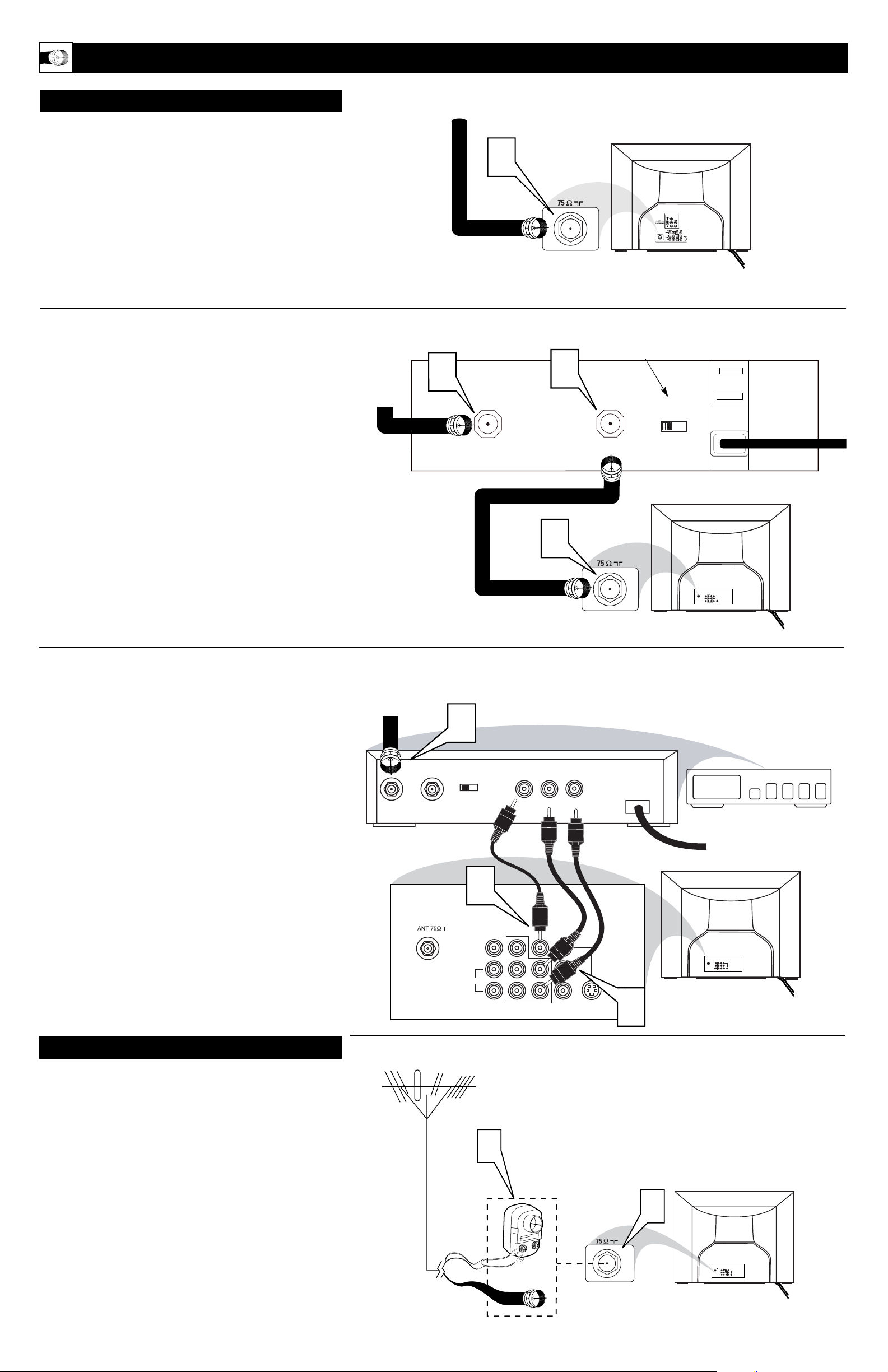
Direct Cable Connections:
This connection will supply Stereo sound to the TV.
1
Connect the open end of the round Cable Company supplied cable to the 75Ω input on the TV. Screw it down finger
tight.
Cable Box (w/RF In/Outputs):
This connection will NOT supply Stereo sound to the TV. The sound
from the cable box will be mono.
2
Connect the open end of the round Cable Company supplied cable to
the cable signal IN(put) plug on the back of
the Cable Box.
3
Using a separate round coaxial cable, connect one end to the
OUT(put) (TO TV) plug on the back of the Cable Box.
4
Connect the other end of the round coaxial cable to the
75Ω input on the back of the television. Screw it down finger
tight.
NOTE: Be sure to set the OUTPUT CHANNEL SWITCH on the
back of the cable box to CH 3 or 4, then tune the TV to the corresponding channel. Once tuned, change channels at the cable box, not
the television.
Cable Box (w/Audio/Video Outputs):
This connection will supply Stereo sound to the TV.
5
Connect the open end of the round Cable Company supplied cable to
the cable signal IN(put) plug on the back of
the Cable Box.
6
Using a RCA type Video Cable, connect one end of the
cable to the Video (or ANT, your cable box may be labeled
differently) Out jack on the cable box and the other end to the
AV1 Video Input on the TV.
7
Using a RCA type Audio Left and Right Cable, connect one
end to the left and right Audio Out L & R jacks on the
cable box. Connect the other end to the AV1 Audio L & R
Input jacks on the TV.
NOTE: Use the Channel +, or – buttons on the TV remote control to
tune to the AV1 channel for the cable box signal. Once tuned, change
channels at the cable box, not the television.
C
ABLE
/CABLE BOX TV
Direct Cable Connection:
Cable Box with RF Inputs and Outputs Connection:
Cable signal
coming from
Cable Company
(Round 75Ω
coaxial cable)
Jack Panel Back of TV
Jack Panel Back
of Cable Box
Cable Signal
IN from the
Cable
Company
Round 75Ω
Coaxial Cable
Jack Panel Back of TV
A
combination antenna receives normal broadcast channels (VHF 2–13 and UHF 14–69). Your connection is
easy because there is only one 75Ω (ohm) antenna plug on
the back of your TV, and that’s where the antenna goes.
1
If your antenna has a round cable (75 ohm) on the end,
then you're ready to connect it to the TV.
If your antenna has flat, twin-lead wire (300 ohm), you
first need to attach the antenna wires to the screws on a
300- to 75-ohm adapter.
2
Push the round end of the adapter (or antenna) onto the
75Ω (ohm) plug on the back of the TV. If the round end of
the antenna wire is threaded, screw it down finger tight.
A
NTENNA TV
1
2
ANT 75‰
L/Mono
Monitor out
VIDEO
S-VIDEO
AV1 in
Y
Pb
Pr
AV2 in
AUDIO
R
COMPONENT VIDEO INPUT
Antenna Connection:
Jack Panel Back of TV
Round 75Ω Coaxial
Cable from Antenna
Twin
Lead Wire
300 to 75-ohm
Adapter
Outdoor or Indoor Antenna
(Combination VHF/UHF)
The combination antenna receives normal
broadcast channels 2-13 (VHF) and 14-69 (UHF).
Cable Box with Audio/Video Outputs Connection:
Cable Signal IN
from the Cable
Company
Jack Panel Back
of Cable Box with A/V Outputs
Jack Panel Back of TV
Audio Cables
L& R (Red, White)
Video Cable (Yellow)
Output Channel Switch
2
3
CABLE
IN
OUTPUT
CH
TO TV
3 4
4
CABLE
IN
5
OUTPUT
CH
3 4
TO
TV
VIDEO
OUT
LR
AUDIO
OUT
ANT 75‰
Monitor out
AV1 in
VIDEO
Y
L/Mono
Pb
AUDIO
R
Pr
COMPONENT VIDEO INPUT
24
AV2 in
S-VIDEO
6
Monitor out
VIDEO
L/Mono
AUDIO
R
AV1 in
COMPONENT VIDEO INPUT
AV2 in
Y
Pb
Pr
S-VIDEO
7
ANT 75‰
AV2 in
Monitor out
AV1 in
VIDEO
Y
L/Mono
Pb
AUDIO
S-VIDEO
R
Pr
COMPONENT VIDEO INPUT
Page 3
HOOKING UP THE TV
C
omponent Video inputs provide for the highest possible color
and picture resolution in the playback of digital signal source
material, such as with DVD players. The color difference signals
(Pb, Pr) and the luminance (Y) signal are connected and received
separately, which allows for improved color bandwidth information (not possible when using composite video or S-Video connections).
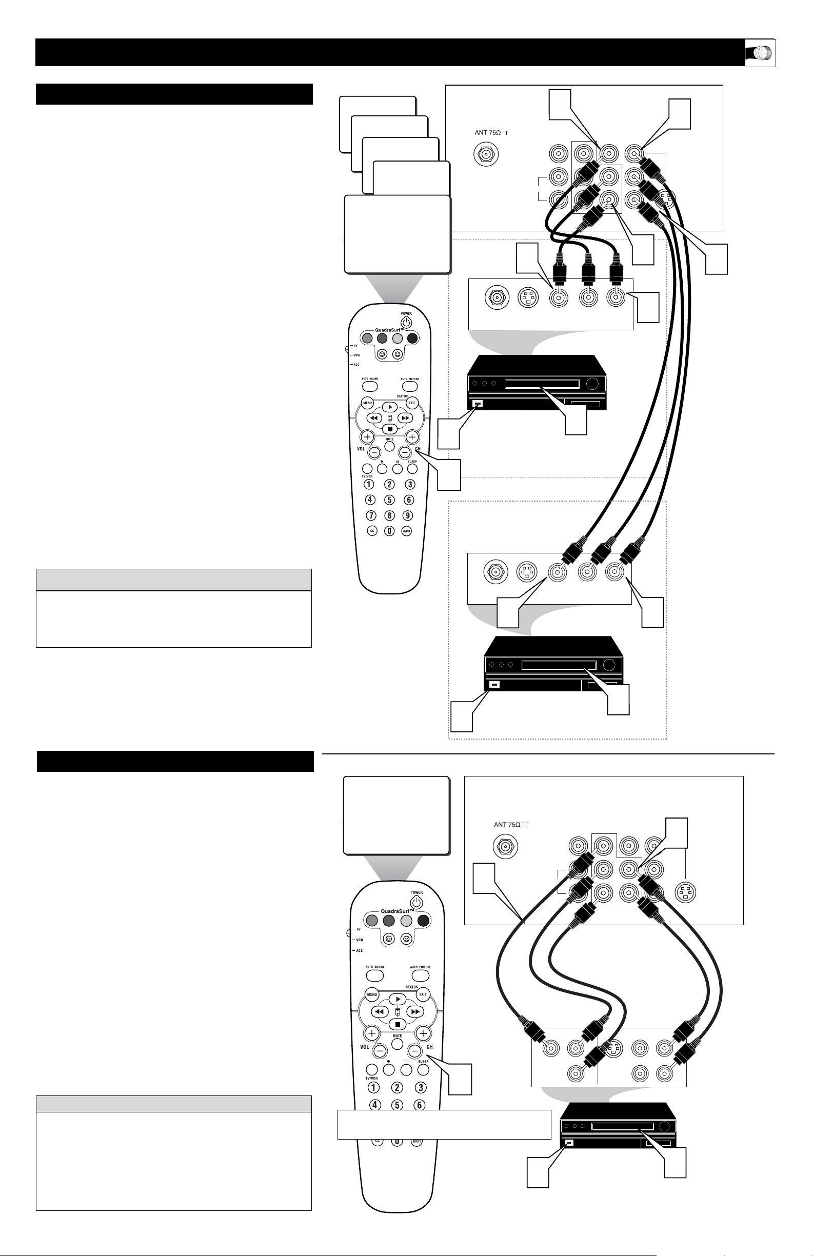
1
Connect the Component (Y, Pb, Pr) Video OUT jacks
from the DVD player (or similar device) to the (Y, Pb, Pr)
in(put) jacks on the TV. When using the Component Video
Inputs, it is best not to connect a signal to the AV1 in Video
Jack.
2
Connect the red and white AUDIO CABLES to the
Audio (left and right) output jacks on the rear of the accessory device to the Audio (L and R) AV1 in Input Jacks on
the TV.
3
Turn the TV and the DVD (or digital accessory device)
ON.
4
Press the CH +, – buttons to scroll the available channels
until CVI appears in the upper left corner of the TV screen.
5
Insert a DVD disc into the DVD player and press the
PLAY
button on the DVD Player.
COMPONENT VIDEO INPUTS
The description for the component video connectors may differ
depending on the DVD player or accessory digital source equipment used (for example, Y, Pb, Pr; Y, B-Y, R-Y; Y, Cr, Cb).
Although abbreviations and terms may vary, the letters b and r
stand for the blue and red color component signal connectors,
and Y indicates the luminance signal. Refer to your DVD or
digital accessory owner’s manual for definitions and connection
details.
HELPFUL HINT
3
T
he TV’s audio/video input jacks are for direct picture and
sound connections between the TV and a VCR (or similar
device) that has audio/video output jacks. Both the AV1 and AV2
Input Jack connections are shown on this page, but either one can
be connected alone. Follow the easy steps below to connect your
accessory device to the AV1 and AV2 in Jacks located on the back of
the TV.
1
Connect the VIDEO (yellow) cable to the VIDEO AV1 in
(or AV2 in) jack on the back of the TV.
2
Connect the AUDIO (red and white) cables to the
AUDIO (left and right) AV1 in (or AV2 in) jacks on the
rear of the TV.
3
Connect the VIDEO (yellow) cable to the VIDEO OUT
jack on the back of the VCR (either one or two) or accessory device being used.
4
Connect the AUDIO (red and white) cables to the
AUDIO (left and right) OUT jacks on the rear of the VCR
(either one or two) or accessory device being used.
5
Turn the VCR (either one or two) or accessory device
and the TV ON.
6
Press the CH + or – buttons on the remote control to
select the AV1 channel for accessory device number one, or
the AV2 channel for accessory device number two. AV1 or
AV2 will appear in the upper left corner on the TV screen
depending on the channel chosen.
7
With either of the VCRs (or accessory devices) ON and a
prerecorded tape (CD, DVD, etc.) inserted, press the
PLAY button to view the tape on the television.
AV1 & AV2 I
NPUTS
Note: The Audio/Video cables needed for this connection are
not supplied with your TV. Please contact your dealer or Philips
at 800-531-0039 for information about purchasing the needed
cables.
cc
C
HECK IT OUT
AUDIO IN
(RED/WHITE)
VCR TWO (or accessory device)
(EQUIPPED WITH VIDEO AND
AUDIO OUTPUT JACKS)
VIDEO IN
(YELLOW)
BACK OF VCR
BACK
OF TV
AV 1
Connection
AV 2
Connection
VCR ONE (or accessory device)
(EQUIPPED WITH VIDEO AND
AUDIO OUTPUT JACKS)
AUDIO CABLES
(RED/WHITE)
COMPONENT
VIDEO CABLES
(Green, Blue, Red)
BACK OF TV
ACCESSORY DEVICE
EQUIPPED WITH COMPONENT
VIDEO OUTPUTS.
The CVI connection will be dominate over the AV1 in Video Input.
When a Component Video Device is connected as described, it is best
not to have a video signal connected to the AV1 in Video Input jack.
24
SVHS
AV2
CVI
AV1
ANT/CABLE
OUT
2
S-VIDEO
VIDEO
L/Mono
OUT
AUDIO
1
Monitor out
R
COMPONENT VIDEO INPUT
R L
AUDIO OUT
AV1 in
Y
Pb
Pr
VIDEO
OUT
3
AV2 in
S-VIDEO
2
4
1
7
VOL
5
6
CVI
VOL
5
4
ANT/CABLE
OUT
1
S-VIDEO
OUT
R L
AUDIO OUT
4
Monitor out
VIDEO
L/Mono
AUDIO
R
COMPONENT VIDEO INPUT
COMP VIDEO
Y
VIDEO
OUT
7
AV1 in
Y
Pb
Pr
S-VIDEO
Pb
OUT
Pr
3
AV2 in
VIDEO
OUT
2
AUDIO
R
OUT
L
S-VIDEO
3
5
Page 4
HOOKING UP THE TV
T
he Monitor (Audio/Video) out jacks are great for recording
with a VCR or used to connect an external audio system for
better sound reproduction.
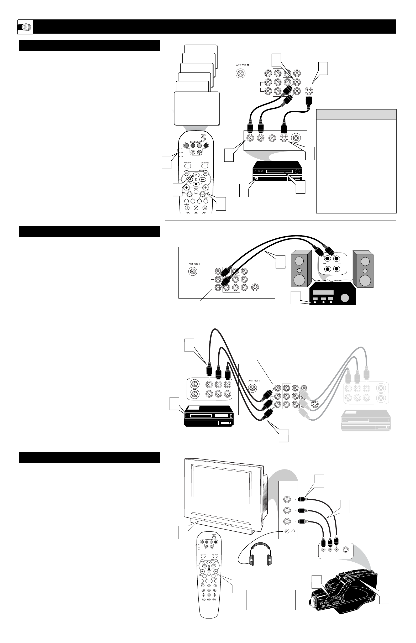
For Audio System Connection:
1
Connect one end of the R(ight) and L(eft) AUDIO
(Monitor Out) jacks on the TV to the R and L audio input
jacks on your amplifier or sound system. Set the audio system’s volume to a normal listening level.
2
Turn the TV and audio system ON. You can now adjust
the sound level coming from the audio system with the
VOLUME (+) or (–) button on the TV or remote control.
For Second VCR Connection/Recorder:
NOTE: Refer to page 9 for the proper hookup of the first VCR.
Follow the instructions on how to tune to the AV 1 channel to
view a pre-recorded tape.
The following steps allow you to connect a second VCR to
record the program while your watching it.
3
Connect one end of the yellow Video Cable to the
Monitor out VIDEO plug. Connect the other end to the
VIDEO IN plug on the second VCR.
4
Connect one end of the red and white Audio cable from
the Monitor out AUDIO L and R plugs on the TV to the
AUDIO IN plugs on the VCR.
5
Turn the Second VCR ON, insert a black VHS tape and
it’s ready to record what’s being viewed on the TV screen.
MONITOR OUTPUTS
4
T
he S(uper)-Video connection on the rear of the TV can provide
you with better picture detail and clarity for the playback of
accessory sources than the normal antenna picture connections.
NOTE: The accessory device must have an S-VIDEO OUT(put)
jack in order for you to complete the connection on this page.
1
Connect one end of the S-VIDEO CABLE to the SVIDEO jack on the back of the TV. Then connect one end
the AUDIO (red and white) CABLES to the AV2 in
AUDIO L and R(left and right) jacks on the rear of the TV.
2
Connect other end of the S-VIDEO CABLE to the SVIDEO OUT jack on the back of the VCR. Then connect
the other ends of the AUDIO (red and white) CABLES to
the AUDIO (left and right) OUT jacks on the rear of the
VCR.
3
Turn the VCR and the TV ON.
4
Press the CH + or – buttons on the remote to scroll the
channels until SVHS appears in the upper left corner of the
TV screen.
5
Slide the TV/VCR/ACC switch to the VCR position.
6
Now your ready to place a prerecorded video tape in the
VCR and press the PLAY button
.
S-V
IDEO INPUTS
SIDE AUDIO/VIDEO INPUTS
The S-VIDEO and VIDEO AV2
in(puts) are in parallel. The SVIDEO input is dominant when in
use. If separate video signals are
connected to the S-VIDEO and
VIDEO AV2 in(puts), the signal
from the VIDEO AV2 in(put) will
not be usable.
Note: The S-Video and Audio
cables needed for this connection
are not supplied with your TV.
Please contact your dealer or Philips
at 800-531-0039 for information
about purchasing the needed cables.
HELPFUL HINT
A
udio and Video Side Inputs are available for a quick connec-
tion of a VCR, to playback video from a camera or attach a
gaming device. Use the CH + or – buttons on the remote control
to tune these inputs.
1
Connect the video (yellow) cable from the Video output
on the Camera (or accessory device) to the Video (yellow)
Input located on the Side of the TV.
2
For Stereo Devices: Connect the audio cable (red and
white) from the Audio Left and Right Outputs on the
Camera to a Stereo to Mono adapter. Then plug the single
end of the adapter to the Audio In (white) jack on the Side
of the television.
For Mono Devices: Connect one end of the audio cable
from the Audio Out jack on the device to the Audio In
(white) jack on the Side of the television.
3
Turn the TV and the accessory device ON.
4
Press the CH + or – buttons on the remote control to tune
the TV to the side input jacks. “Front” will appear on the
TV screen.
5
Press the PLAY button on the accessory device to
view playback, or to access the accessory device (camera,
gaming unit, etc.).
AUDIO CABLE
(RED/WHITE)
VCR
(EQUIPPED WITH
S-VIDEO JACKS)
S-VIDEO
CABLE
BACK OF VCR
JACK PANEL
Located on the back of the TV
AUDIO CABLES
(Red & White)
AUDIO SYSTEM
with AUDIO INPUTS
AV OUT
AUDIO L(eft) and R(ight)
JACK PANEL
Located on the back of the TV
AUDIO CABLES
(Red & White)
FIRST VCR (accessory device)
(Hookup from AV1 on previous page.)
Monitor OUT
VIDEO &AUDIO
L(eft) and R(ight)
SECOND VCR
VIDEO CABLE
(Yellow)
Jack Panel located
on the Side of TV
Jack Panel
of Accessory Device
Video Cable
(yellow)
Audio Cables
(red & white)
Optional
Headphones
When headphones re used
the sound coming from the
TV speakers will be mute.
Audio System Connection
Second VCR Connection/Recorder
5
6
Front
SVHS
AV2
CVI
2
AV1
24
2
VOL
3
Monitor out
VIDEO
L/Mono
AUDIO
R
L R
AUDIO OUT
COMPONENT VIDEO INPUT
VIDEO
OUT
4
AV1 in
Y
Pb
Pr
S-VIDEO
OUT
AV2 in
ANT/CABLE
OUT
6
1
S-VIDEO
1
Monitor out
VIDEO
L/Mono
AUDIO
R
COMPONENT VIDEO INPUT
AV1 in
Pb
Pr
AV2 in
Y
S-VIDEO
3
ANTENNA
ANTENNA
IN
OUT
OUT OUT
VIDEO
IN
RL
AUDIO
IN
5
Monitor out
VIDEO
L/Mono
AUDIO
R
1
2
AV2 in
AV1 in
Y
Pb
Pr
COMPONENT VIDEO INPUT
R
L
T
U
P
IN
V
/T
X
U
A
T
U
P
IN
O
N
O
H
P
S-VIDEO
ANTENNA
OUTOUT
IN
VIDEO
LR
AUDIO
IN
ANTENNA
OUT
IN
3
Front
VOL
4
4
VIDEO
L
AUDIO
R
1
VIDEOAUDIO
LEFT RIGHT
5
2
S-VIDEO
3
 Loading...