

Page 1
FL-1 Wide LCD Monitor / TV
Service
Service
Service
FL-1-26 FL-1-32
26MF605W/17
32
MF605W/17
""
Horizontal frequencies
30-50kHz
TABLE OF CONTENTS
Description Page
Important Safety Notice---- ------------------------------ 2
Technical Data-------------------------------------------3~4
Instalation/On Screen Display------------------------5~7
Troubleshooting--------------------------------------------8
Lock/unlock,Aging,Factory mode-----------------------9
Circuit Description-----------------------------------10~11
Mechanical Instructions----------------------------12~13
Definition of pixel defects -------------------------------14
Warning Message ----------------------------------------15
Electrical instruction --------------------------------16~20
DDC Instructions-------------------------------------21~27
Failure mode of panel------------------------------------28
Safety Test Requirments--------------------------------29
ISP Instructions --------------------------------------30~32
Repair tips---------------------------------------------33~34
SAFETY NOTICE
ANY PERSON ATTEMPTING TO SERVICE THIS CHASSIS MUST FAMILIARIZE HIMSELF WITH THE CHASSIS
AND BE AWARE OF THE NECESSARY SAFETY PRECAUTIONS TO BE USED WHEN SERVICING ELECTRONIC
EQUIPMENT CONTAINING HIGH VOLTAGES.
Description Page
Color adjustment------------------------------------35~36
Repair Flow chart-----------------------------------37~38
Block Diagram---------------------------------------39~40
Wiring Diagram------------------------------------------41
Scaler Diagram&C.B.A. ---------------------------42~58
Power Diagram & C.B.A. --------------------------59~62
HD Diagram & C.B.A. ------------------------------63~65
IR Diagram & C.B.A. -------------------------------66~68
Key Diagram & C.B.A. -----------------------------69~70
Side AV Diagram & C.B.A. ------------------------71~73
Exploded View------------------------------------------- 74
Spare/recommended parts list ------------------75~79
General product specification--------------------80~97
DDC DATA------------------------------------------98~103
Different parts list--------------------------------------104
CAUTION: USE A SEPARATE ISOLATION TRANSFORMER FOR THIS UNIT WHEN SERVICING.
REFER TO BACK COVER FOR IMPORTANT SAFETY GUIDELINES
Published by BCU Monitors Printed in Suzhou Copyright reserved Subject to modification K Feb. 01 2005
GB
3138 106 10446
Page 2
2
26MF605W/17
Important Safety Notice
Go to cover page
Proper service and repair isimportant to the safe, reliable
operation of all HPConsumer Electronics Company**
Equipment. The service procedures recommended by HP and
described in this service manual are effective methods of
performing service operations. Some ofthese service
operations require the use of tools specially designed for the
purpose. The special tools should be used when and as
recommended.
It is important to note that this manual contains various
CAUTIONS and NOTICES which should be carefully read in
order to minimize the risk of personal injury to service
personnel. The possibility exists that improper service
methods may damage the equipment. It is also important to
understand that these CAUTIONS and NOTICES ARE NOT
EXHAUSTIVE. HP could not possibly know, evaluate and
advise the service trade of all conceivable ways in which
service might be done or of the possible hazardous
consequences of each way. Consequently, HP has not
undertaken any such broad evaluation. Accordingly, a
servicer who uses a service procedure or tool which is not
recommended by HP must first satisfy himself thoroughly that
neither his safety nor the safe operation of the equipment will
be jeopardized by the service method selected.
* * Hereafter throughout this manual, HP Consumer
Electronics Company will bereferred to as HP.
WARNING
Critical components having special safety characteristics are
identified with a bythe Ref. No. inthe parts list and
enclosed within a broken line*
(where several critical components are grouped in one area)
along with the safety symbol on the schematics or
exploded views.
Use of substitute replacement parts which do not have the
same specified safety characteristics may create shock, fire,
or other hazards.
Under no circumstances should the original design be
modified or altered without written permission from Philips.
Philips assumes no liability, express or implied, arising out of
any unauthorized modification of design.
Servicer assumes all liability.
*BrokenLine
FOR PRODUCTS CONTAINING LASER :
DANGER- Invisible laser radiation when open.
AVOID DIRECT EXPOSURE TO BEAM.
CAUTION- Use of controls or adjustments or
performance of procedures other than
those specified herein may result in
hazardous radiation exposure.
CAUTION- The use of optical instruments with this
product will increase eye hazard.
TO ENSURE THE CONTINUED RELIABILITY OF THIS
PRODUCT, USE ONLY ORIGINAL MANUFACTURER'S
REPLACEMENT PARTS, WHICH ARE LISTED WITH THEIR PART
NUMBERS IN THE PARTS LIST SECTION OF THIS
SERVICE MANUAL.
Take care during handling the LCD module with backlight
unit
- Must mount the moduleusing mounting holes arranged infour
corners.
- Do not press onthe panel, edge of theframe strongly or electric
shock as this will result in damage to the screen.
- Do not scratch orpress on the panel withany sharp objects, such
as pencil or pen asthis may result in damage to the panel.
- Protect the module fromthe ESD as it maydamage the electronic
circuit (C-MOS).
- Make certain that treatment person s body are grounded through
wrist band.
- Do not leave themodule in high temperature andin areas of high
humidity for a long time.
- Avoid contact with water as it may ashort circuit within the module.
- If the surface ofpanel become dirty, please wipe it off with a soft
material. (Cleaning with a dirty or rough cloth may damage the
panel.)
Page 3
Technical Data
26MF605W/17
Go to cover page
3
LCD panel
Type NR. : )
Out dimensions : 626.0(H) x 373.0(V) x 44.1(D) mm (Typ.)
line
Pitch (mm) : 0.4215(H) x 0. (V)
Pixel format : 1 hori. By 7 vert. pixels
Color pixel arrangement: RGB vertical stripe
Display surface : Anti-glare
Number of color : ( bits)
Backlight : FL
Active area (WxH) :
View angle
Contrast ratio : Typical : 1
uminance : ( )
L of white 500 cd/m Center 1 points, Typ.
AC-input : 90V ~ 264V
Power consumption : W
Power cord length : 1.8M
Power cord type : 3 lead with earth plug , plugable (US type)
Power indicator : LED (On: Green ,Sleeping mode: Amber )
Auto power saving : EPA, Nutek, VESADPMS
Horizontal scan : 30 KHz
Vertical scan : 56 Hz
Display mode : Multi-modes
Horizontal scanning
Vertical scanning
White balance Adjustment
Note: Use Minolta CA-110 for color coordinates and luminance check.
Normal X (center) = 0.289 ± 0.030
(8500 ° K CIE Coordinates) Y (center) = 0.304 ± 0.030
LC260WX2 (Supplier LPL
366 68
Hard coating(3H), treatment
of the front polarizer
16,777,216 colors 8
18 EE
575.769mm x 323.712mm
: Viewing angle free(R/L 176(Typ.),
U/D 176(Typ.))
70 /Typ(at PC mode),105W/Typ(at TV
mode).
~50
~63
Sync polarity : Positive or negative
Scanning frequency : 30 ~ 50 KHz
Sync polarity : Positive or negative
Scanning frequency : 56 ~ 63 Hz
4215
600
2
AC,50/602Hz
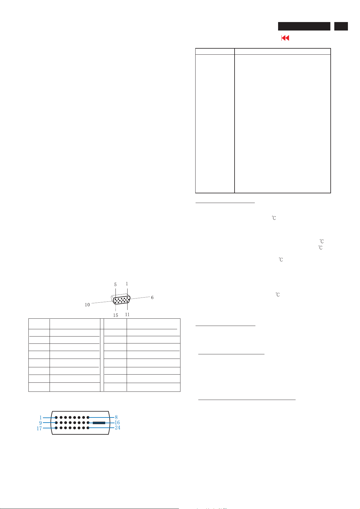
Pin No. Description
1RX22RX2+
3GND
4GND
5GND
6 DDC clock
7 DDC data
8GND
9RX110 RX1+
11 GND
12 GND
13 GND
14 +5V
15 DVI-D self test
16 +5V
17 RX018 RX0+
19 GND
20 GND
21 GND
22 GND
23 RXC+
24 RXC-
Environmental conditions
Operating
- Temperature : 0 to 40
- Humidity : 10 to 95%(non - condensing)
- Altitude : 0 to 12000 feet
- Air pressure : 600 to 1100 mBAR
- (guaranteed optical performance) : 5 to 35
- (guaranteed functional performance) : 5 to 40
Storage
- Temperature : -20 to 50
- Humidity : 10 to 95% (non - condensing )
- Air pressure : 600 to 1100 mBAR
Note:recommendat0to35°C, Humidity less than 60 %
Pin Assignment
Pin No.
2
3
4
5
6
7
8
Input DVI-D connector pin
Assignment
Red video input
1
Green video input
Blue video input
GND
Cable detect
Red video GND
Green video GND
Blue video GND
Pin No.
9
10
11
12
13
14
15
Assignment
DDC +3.3V OR +5V
GND
GND
Serial data line (SDA)
H-sync
V-sync
Data clock line (SCL)
Shipping
- Temperature :( -20 to 50
- Humidity : 10 to 95% (non - condensing )
- Altitude : 0 to 40000 feet ( non operating )
- Air pressure : 600 to 1100
Marking and identification
In accordance with UAN-D1109 and the approval marking required by
the countries of destination.
Safety and EMI requirements
Safety requirement: CSA C22.2 NO.950-95, UL1950, UL, CSA, NOM
Ergonomic Requirement: TUV/GS, TUV/ERG, ISO13406-2 And the
relevant national safety standards.
EMI requirement : FCC Part 15 Class B, ICES-003
Power Management: EPA
Electri cal c haracter istics and perfor mance
Test signal and test method in accordance with test instructions sheet
161 of the product where applicable.
Input signals
a. Analog Video : 15 pin D-Sub 0.7 Vp-p linear, positive
polarity and separate Sync ( TTL level,
positive or negative polarity )
b. Audio signal : Mini-jack audio input
c. Signal source : Pattern generator format as attachment (
Timing table 1 to 6 )
d. Reference generator : CHROMA 2135 or 2250
)
Page 4
4
26MF605W/17
Technical Data(Continued)
Go to cover page
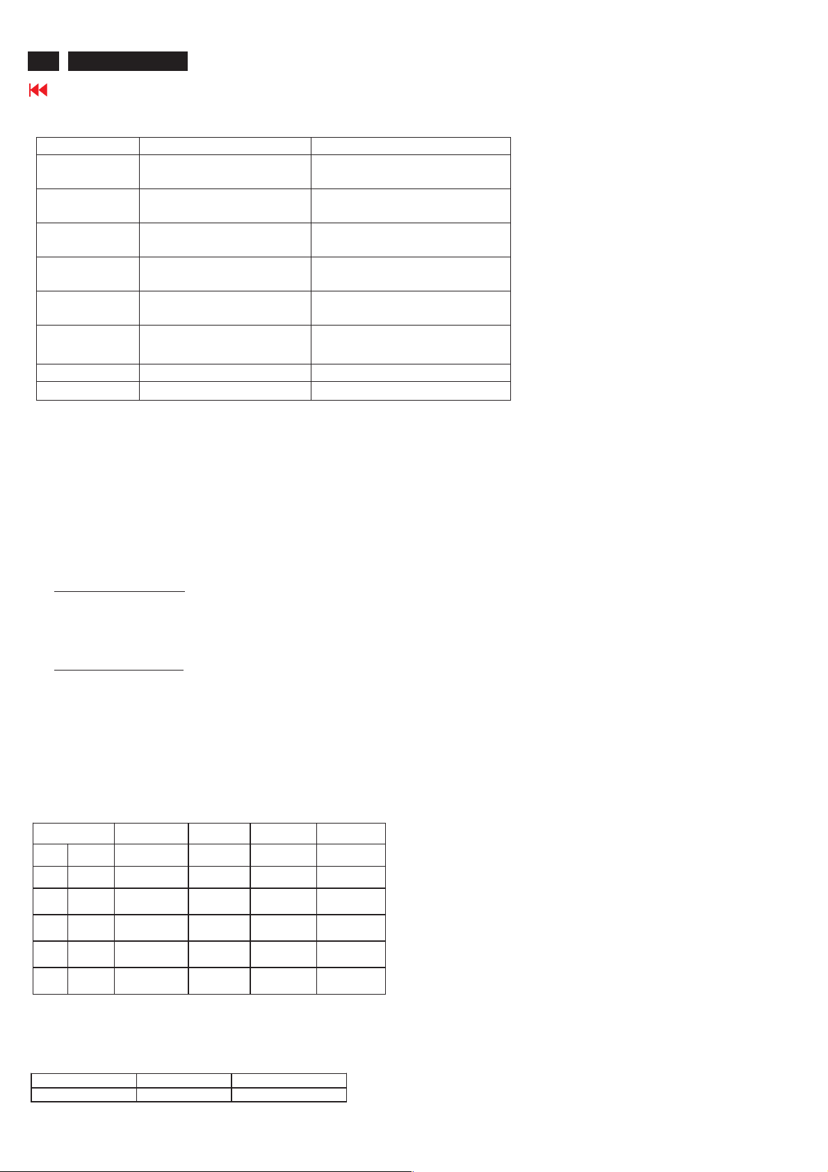
TV Signal type :
Signal type Video signal Audio signal
Video1/Video2/
Video3
S-Video1/
S_Video2
Component InputRCA Jack, Y, Pb , Pr,
PVR Output (CVBS include Tuner)
DVI IN Digital TV signal support
HD IN Input RCA Jack, Y, Pb, Pr
RF IN Aerial Input
Headphone Output 3.5mm stereo jack
Front/Top control panel definition:
Power SW : Power switch.
Power LED : Normal operationàGreen.
+Up/Down- : Channel up and down, and OSD cursor up and down.
-Left/Right+ : Volume up and down, and OSD cursor left and right
Menu : Enable and EXIT OSD menu(enter key for PC).
IR receiver : Sense the signal from RC handset.
Input RCA Jack, Yellow Share with S-Video or Component
RCA Jack , White / Red
Input S-terminal, Black Share with Video1/Video2
RCA Jack, white / Red
Share with Video3
Green, Blue, Red
RCA Jack , Yellow
HDCP DVI connector
Green, Blue, Red
Sleeping modeàAmber.
RCA Jack, white / Red
Output (CVBS audio)
RCA Jack, white / Red
Input, L/R RCA Jack,
white / Red
Input, L/R RCA Jack,
white / Red
Remote control unit definition
Function Keys
The remote control is used in all PC and TV modes:
At PC mode function keys:
1. Press MENU Key to call Monitor Menu
2. Press Up/Down/Left/Right Key to select Monitor function
3. Left/Right is Volume Hot Key.
4. Use remote controller to control all PC menu function.
At TV mode function keys:
1. Press MENU Key to display TV Menu
2. Press Up/Down/Left/Right Key to select TV function
3. Up/Down Key is Channel Hot Key.
4. Left/Right Key is Volume Hot Key.
5. Use remote controller to control all TV menu function.
Display (for preset mode only)
Actual display size: 575.769mm X 323.712mm
Resolution
Factory Preset modes (6 modes)
Dot rate (MHz) H.freq (KHz) Mode Resolution V.freq (Hz)
25.175 31.469 IBM VGA 640 * 480 59.94
36 35.156 VESA 800 * 600 56.25
40.00 37.879 VESA 800 * 600 60.316
65.00 48.363 VESA 1024 * 768 60.004
CVT 74.5 47.772 WXGA 1280 * 720 59.855
CVT 79.5 47.776 WXGA 1280 * 768 59.87
Brightness output (Video signal 0.7V ± 2%)
Apply a 1280X768@60Hz signal with full white pattern, the center of
screen at original color brightness light output is
Brightness control Contrast control Light output Unit: nit
100% 100%
> 400
Page 5
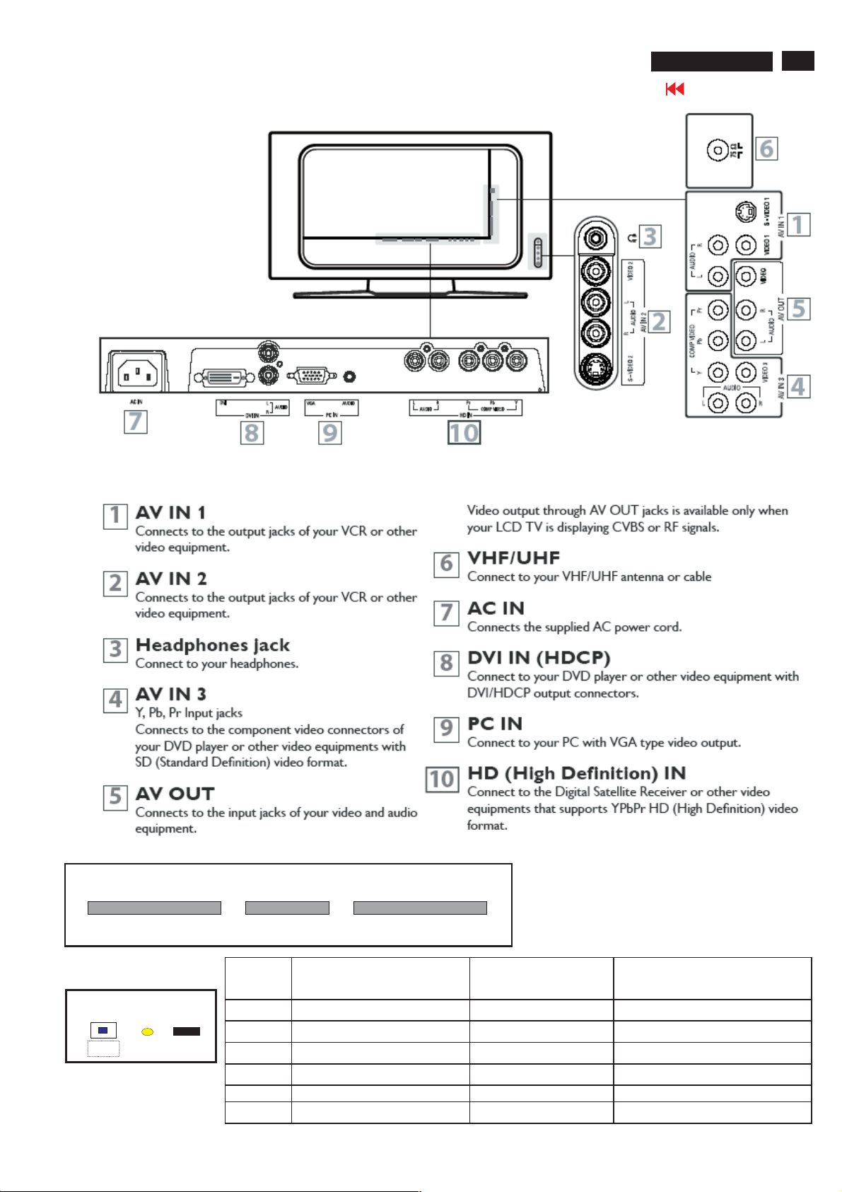
Installation
26MF605W/17
Go to cover page
5
Top Control
-
Volume
<B> <C> <D> <E> <F>
Front Control
Power SW
<A>
LED
RC sensor
+
RightLeft
Menu
-
Channel
Key Function VGA mode TV/video mode
<A> Power DC Power DC Power
<B> Left Left/Volume down Left/Volume down
<C> Right Right/Volume up Right/Volume up
<D> Menu Enter /Exit OSD menu Enter /Exit OSD menu
<E> Menu Down/channel down Menu line Down Menu Down/Channel Down
<F> Menu Up/Channel up Menu line Up Menu Up/Channel up
+
UpDown
Page 6

6
26MF605W/17
Go to cover page
Installation
Page 7

OSD Menu list
PC Signal control via front keyboard:
On Screen Display
TV Signal control via front keyboard :
Picture
Smart picture : Personal/Movie/Sport/weak signal/multimedia/
Brightness : Adjust brightness
Color : Adjust color saturation
Contrast : Adjust contrast.
Sharpness : Adjust sharpness
Tint : Adjust skin color
Audio
Smart sound : Personal/News/Music/Theatre
Setting : Treble/base/balance adjustment
Stereo : Stereo/mono select
Virtual surround: Virtual surround on/off
AVL : Auto volume limit on/off
Night
26MF605W/17
Go to cover page
7
Picture
Smart picture :Normal, warm, cool
Brightness :Adjust backlight
Contrast : Adjust contrast.
Auto adjust : Yes/no for PC auto alignment.
Manual adjust : Phase/clock/Horizontal/vertical
Audio
Smart sound : Personal/News/Music/Theatre
Setting : Treble/base/balance adjustment
Stereo : Stereo/mono select
Virtual surround: Virtual surround on/off
AVL : Auto volume limit on/off
Featu re
PIP : Size (small/medium/large/PBP);
Video (TVàVideo1àVideo2àVideo3à
S-Video1à S-Video2àComponentàTV )
Audio (PIP/PC)
Display (to change PIP display position)
Source : PCàDVIàTVàVideo1àVideo2àVideo3à
S-Video1àS-Video2àComponentàHDà PC
Install
Language : English/ Espanol / Francias
Factory reset : Recall Contrast, Brightness.
Feature
Source : TV/Video1 / Video2 / Video3 / S-Video1/
S-Video2/Component/HD/PC/DVI/TV.
Picture format : WIDESCREEN / 4:3/ ZOOM 16:9 / SUPER
WIDE /
Auto lock : Lock program/change code/clear all/block
option/movie rating/TV rating.
Close caption : caption mode (CC1;CC2;CC3;CC4;TXT1;TXT2;
TXT3;TXT4;CC mute)
CC display (CC on/off)
Color Temp : Normal/warm/cool
Ins tall
Language : English/ Espanol / Francias
Tuner mode : Antenna/cable/auto.
Auto program: Start
Channel edit : Channel(select channel)/Skipped(skip/
active).
Factory reset : Yes
Page 8

8
26MF605W/17
Troubleshooting
Go to cover page
No Power
1. Check the TV power cord. Disconnect the power cord from the power outlet for 10 seconds,
then reinsert the plug into the outlet. Press POWER to turn on the TV again.
2. Make sure the outlet is not on a wall switch.
3. Make sure a fuse has not blown at the power outlet.
No Picture
1. Check the antenna or Cable TV connections. Connect the antenna or Cable TV signal securely to the TV s
75 jack on the rear of the TV.
2. Set TUNER MODE correctly. Details are on page 18.
3. Activate AUTO PROGRAM to find all available channels. Details are on page 19.
4. In case you hear only sound and don
have connected Video signal to S-Video or Video (CVBS) input. Only one of the two video inputs can be
connected to sound. This means that the same sound can be heared in S-Video and Video (CVBS) mode.
t see any picture in S-Video or Video (CVBS) mode. Please check if you
No Sound
1. Press the VOL+ and VOL- buttons to adjust the volume.
2. Press the MUTE button on the remote control to cancel or restore the volume.
3. If you have connected other equipment to the TV (such as a VCR or DVD Player), make sure the audio cables
are connected securely between the TV and the other equipment.
4. Check the SOUND settings. Details are on page 22 or 24.
5. In case you hear wrong sound in S-Video or Video (CVBS) mode. Please check if you have connected the right
sound signal to AV in (S-Video or Video input). Only one of the two video inputs can be connected to sound,
but both video signals can be connected. This means that only one of the two sound inputs can be heared in
S-Video and Video (CVBS) mode.
Remote Control does not work.
1. Check the batteries. If necessary, replace them with two AAA heavy duty (zinc chloride) or alkaline batteries.
2. Clean the remote control as well as the remote control sensor on the front of the TV.
3. Check the TV power cord. Disconnect the power cord from the power outlet for 10 seconds, then reinsert
the plug into the outlet. Press POWER to turn on the TV again.
4. Make sure the outlet is not on a wall switch.
5. Make sure a fuse has not blown at the power outlet.
6. Always point the remote control toward the front of the TV (toward the remote sensor).
7. Make sure that you use the supplied Magnavox Remote control, only the supplied Magnavox Remote control
canbeusedwiththisLCD-TVset.
TV displays wrong channel or no channels.
1. Repeat channel selection.
2. Add the channel number(s) into the TV
3. Make sure TUNER MODE is set correctly. Details are on page 18.
Then activate AUTO PROGRAM to set up all available channels. Details are on page 19.
s memory. Use STORE. Details are on page 20.
Poor Sound
1. Check if AVL (audio settings menu) is switched on [yes].
2. Select personal smart sound mode and optimize in the Audio onscreen menu the treble and bass settings.
3. Make sure that your external device, for instance VCR, DVD or other AV device has a good quality sound output.
Noisy Picture
1. Select the Weak signal Smart Picture Mode, in this mode noise from bad quality video signals will be suppressed.
Page 9
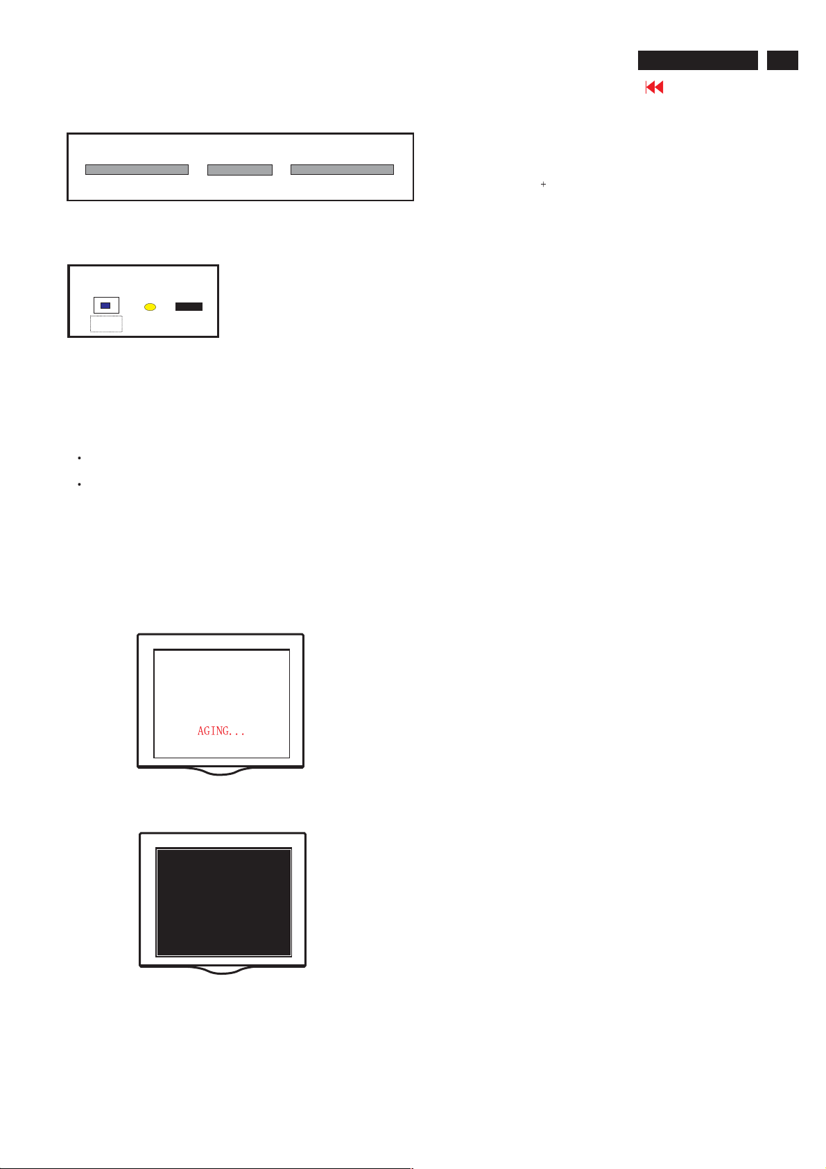
Lock/Unlock,Aging,Factory Mode
26MF605W/17
Go to cover page
9
Top Control
-
Volume
Left
<B> <C> <D> <E> <F>
Right
+
Menu
-
Channel
+
UpDown
Front Control
Power SW
<A>
LED
RC sensor
To Lock/Unlock OSD function
OSD LockThe OSD can be enabled or disabled by pressing and
holding the Menu button on the top panel for 10 seconds. If the
OSD is locked, the warning message "OSD MAIN MANU LOCKED"
displays for three seconds.
If the OSD is locked, press and hold the Menu button for 10
seconds to unlock the OSD.
If the OSD is unlocked, press and hold the Menu button for 10
seconds to lock the OSD.
AGING MODE
No signal input ,power off -> on ,then Into the factory mode, , a full
white pattern will be display on the screen as Fig.1&Fig.2 in stead of
power saving mode. In other words, the power saving function will be
disable in the factory mode.Supply one signal for leaving aging mode.
Access Factory Mode
1). Turn off monitor.
2). Press power "Power " button.Then quickly push " Volume -"
and " Volume ",and hold this two buttons , then the screen
comes out "Waiting For Automatic Adjustment ",then the screen
will be black for one second untill comes out "Windows screen"]
=> then release this two buttons, then press "Menu" button, wait
until the OSD menu with Characters "F1/FL1 NAFTA V0.91.1
041124ADJUST" (below OSD menu) come on the Screen of the
monitor (see Fig. 3).
Fig.3
Scalar Gain R G B Scalar Gain for Normal/Warm/Cool in PC
mode.
Auto-Color Adjust color from received signal (either
in PC or HDTV mode).
ADC Offset R G B Adjust AD 9883 for PC ADC offset.
ADC Gain R G B Adjust AD 9883 for PC ADC gain.
PC Offset R G B PC analog scalar offset.
711X SDTV Brightness Adjust SA 7119 SDTV brightness.
711X SDTV SAT. Adjust SA 7119 SDTV saturation.
711X SDTV Contrast Adjust SA 7119 SDTV contrast.
711X SDTV TINT Adjust SA 7119 SDTV tint (hue).
TV Shift H V Adjust TV screen position
horizontally/vertically.
HD Shift H V Adjust HDTV screen position
horizontally/vertically.
Show Lock Message Show OSD lock message.
HDTVADCOffsetRGB AdjustAD9883forHDTVADCoffset.
HDTVADCGainRGB AdjustAD9883forHDTVADCgain.
Video Scalar Gain R G B Adjust scalar gain for Video mode.
Scalar Hue Adjust scalar hue.
Fig.1
Fig.2
Fig.4
Page 10
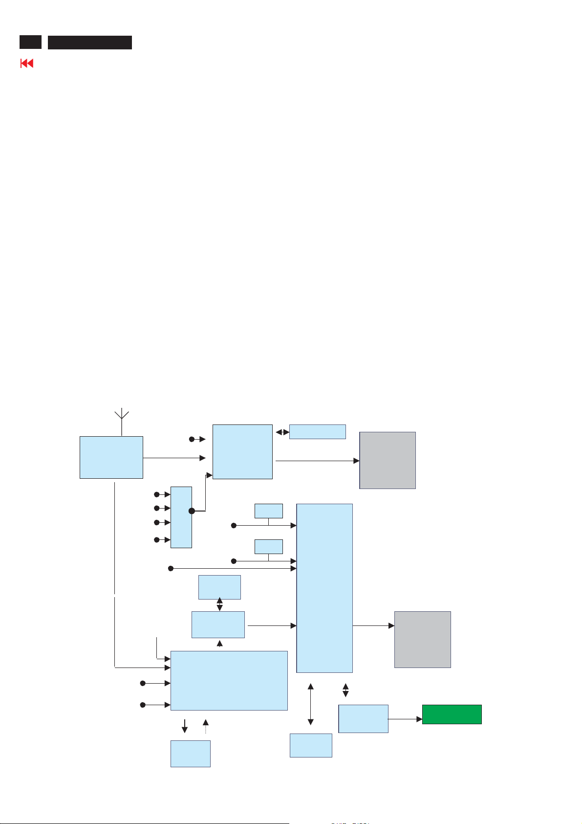
10
26MF605W/17
Circuit Description
Go to cover page
General Description
This LCD TV monitor using FL-1 platform. It can support PC analog signal ( via 15 pin D-Sub input ) and TV signal. It support PIP
function that is TV picture on PC graphic or TV picture on DVI /HDCP. It’s output resolution is up to 1366X768 75Hz for WXGA panel.
It can support DVI HDCP digital signal input and also support TV (RF) , CVBS/ RG B signal ( from SCART1 I/O for Europe model ) ,
CVBS / YC ( from SCART2 I/O for Europe model ) , CVBS/YPbPr ( from Cinch I/O for Non-Europe model ) , CVBS/YC ( from Cinch and S
terminal I/O for Non-Europe model ) , and also have side I/O , support CVBS/YC and Headphone for User easy used .
And It can also support Y Pb Pr signal input (from Cinch I/O) for 480I, 480P, 720P, 1080i 60Hz and 576I, 576P, 720P, 1080I 50Hz HDTV
format input.
Note : For Chinch I/O model two components input is provided one for 480I,480P and 576I, 576P the other for the 480I, 480P, 720P,
1080i 60Hz and 576I, 576P, 720P, 1080I 50Hz HDTV format input.
It also have PVR output function , support and monitor all the CVBS signal output with L/R sound.
This LCD monitor TV use MST51512 as Scaler engine, which has embedded Analog D-sub, digital DVI decoder, scaling input signal for
panel, OSD and simple 3D de-interlace. The extra SDRAM is to accomplish video frame rate conversion and PIP function.
The external CPU can be used for back light control, RC receiver, keypad input, I/O switch control , IIC communication and TV tuning
control, MSP34XX sound decoder control, SAA7119 video decoder control , Columbus IC ( 3D- comb filter ) control , and Audio AMP
TPA3004D sound control .
Video decoder SAA7119 is used for TV video processing and convert it with CCIR 601/16bits or 656/8bits digital format and send to
Columbus IC for 3D comb filter processing and noise reduction processing , after that then send to Scaler for de-interlace process.
One audio decoder MSP34XXG is used for TV sound processing, and output to Class D audio amplifier TPA3004D , then we can have 2
X10W audio output .
In Nafta model CC,V-chip data is decoded in SAA7119 and the scaler OSD display the CC information. The V-Chip is decode by SAA7119
and control via the MCU. In Europe model "Teletext display". Data decode is done by SAA5360, output RGB/FB is to video decoder input for
text overlapping. In non-text model( Nafta. Etc.), this chip is Not used .
Sound decoder
MSP34XX
DVI
HDCP
PC analogTuner CVBS
SDRAM
1Mx16
Columbus
3D
DDC
DDC
AUDIO delay
Scaler
MST51512
Audio
AMP
TPA3004D
LVDS
Panel
Tuner
video
audio
SC1-audio
SC2-audio
audio
DVI Audio
PC audio
HD YPbPr
RGB/YPbPr
AV3 audio
HD audio
2ndIF
M
U
X
SC2 YC , AV3 YC
SC1/SC2/AV3 CVBS
CVBS
MON_OUT
Video Decoder SAA7119
RGB/FB
TT
SAA5360
SDRAM
1Mx16
MCU 128K
Flash
Control Board
IR and key pad
Page 11

Circuit Description
26MF605W/17
Go to cover page
MM tuner is used to receive RF wave and output CVBS and 2nd IF signal. CVBS is to video decoder
(SAA7119) for color process, 2nd IF is to sound decoder (MSP34x5) for audio process. The tuner control is via IIC ex. channel tuning.
For different TV system, tuner and sound decoder have diversity as above.
Standard TV input (Tuner, S-video, CVBS, SCART) is processed by SAA7119, But YPbPr, SDTV and HDTV(480i, 576i,
480p,576p,720p,1080i), is done by scaler MST51512L/502L ADC. But the signal is still link to SAA7119 if PIP (video in graph) function
is requested. Then all YPbPr signal processed by SAA7119 could be the PIP video source. (* May use down sampling in HD0)
MV protect is decoded by scaler.
Video decoder SAA7119, is in charge of color decoding, could support PAL, NTSC and SECAM world wide
system. Compare to SAA7118, SAA7119 improve some picture quality, like V-chip CC I2C read-back, LTI, CTI, skin tone
correction(see task A), also the HD0 is supported, so if F1 need PIP function then the The
Teltext function is for WE model, need a extra IC SAA5360. CVBS input, R/G/B, FB, out. Due to the SAA5360 request input signal
1Vrms and only one input channel, so the CVBS input source is from SAA7119 AOUT (CVBS out with 1Vrms). The R/G/B FB output
into SAA7119 by AI22/AI32/AI42, and AI44 could overlay on any video source.
Sound decoder MSP3415/45 is responsible to sound decode of tuner 2nd IF. It has one 2nd IF, two selectable audio sources input.
And one loudspeaker, one scart out. Due to the input port limitation, a MUX is added for AV source select( PC audio in is fix in SC1). If
the post audio amplifier is gain fixed type then the volume adjust will be on MSP34x5.
Scaler MST51502L/51512L besides scaling function, PIP, 3D de-interlacer, color enhance are major feature.
Even de-interlacer is not so good but for static picture is enough to avoid image sticking.
In America market, to avoid patent issue, two SDRAM is necessary for graph frame buffer. But in else region one SDRAM is
enough. Of course, if no PC mode in spec, then one SDRAM for all model.
The scaler structure limitation, the PIP source only from video port,8bitsor16bits. The sub window /PIP size can enlarge to half
screen.
MCU, NT68F632AL, is 128K flash ROM inside. Power control, RC5 I/O, and key function all done by here.
All chip communication is by IIC (SDA/SCL), and ISP is via DDCIIC, but if PC mode un-supported, then a reserved 6pin connector is
for same application.
11
Page 12

12
26MF605W/17
Go to cover page
Front view
Mechanical Instruction
Back view
Step 1. Remove the stand.
Remove the three screws as Fig.3 and Fig.4
Fig.1
Fig.2
Fig.6
Fig.7
Fig.8
Fig.9
Fig.3
Step 2. Remove the Back cover as Fig.5~8.
a.
Remove the seven screws on the sides and the other
two screws as Fig.5
b. Use thin "I" type screwdriver to open 4 clicks on bottom
side as Fig.6
c.
Use thin "I" type screwdriver to open 3 clicks on right
side as Fig.7
e. Use thin "I" type screwdriver to open 3 clicks on left
side as Fig.8
f. Use thin "I" type screwdriver to open 4 clicks on top
side as Fig.9
g. Remove the back cover as Fig.10 ,then remove the
10 screws as Fig.10,Fig.11,Fig.12
Fig.4
Fig. 10
Fig. 11
Fig. 12
Step 3. Remove the Scaler and Power board.
Remove the 19 screws and disconnect the 9 cables as Fig. 13
and Fig.14
Fig.5
Page 13

Fig. 13
Mechanical Instruction
Fig. 16
26MF605W/17
Go to cover page
13
Fig. 14
Step 4. Disconnect the HD PCB, the Side AV PCB, the KEY PCB , the
IR PCB, as Fig.15the Scaler PCB and power PCB
Fig. 15
Step 5 Remove the MAIN SHIELD ASSY as Fig.16~Fig.18
a.
Remove the 16 screws on the back side as Fig.16
b. on bottom side as Fig.17
Remove the 2 screws
c . on top side as Fig.18
Remove the 2 screws
d. Disconnect the MAIN SHIELD ASSY as Fig.19
Fig. 17
Fig. 18
Fig. 19
In warranty, it is not allowed to disassembly the LCD panel, even the
backlight unit defect.
Out of warranty, the replacment of backlight unit is a correct way
when the defect is cused by backlight (CCFL,Lamp).
Page 14

14
26MF605W/17
Definition of Pixel Defects
Go to cover page
LCD Monitor Quality and Pixel Policy
The TFT monitor uses high-precision technology, manufactured according to HP standards, to guarantee
trouble-free performance. Nevertheless, the display may have cosmetic imperfections that appear as small
bright or dark spots.
This is common to all LCD displays used in products supplied by all vendors and is not specific to the HP LCD.
These imperfections are caused by one or more defective pixels or sub-pixels.
1. A pixel consists of one red, one green, and one blue sub-pixel.
2. A defective whole pixel is always turned on (a bright spot on a dark background), or it is always off (a dark spot
on a bright background). The first is the more visible of the two.3. A defective sub-pixel (dot defect) is less
2. visible than a defective whole pixeland is small and only visible on a specific background.The HP display does
not have more than:
4. bright dots.
5. dark dots.
6. total bright and dark dots.
7. No more than two adjacent (less than 2.5 mm edge-to-edge) defective pixels. To locate defective pixels, the monitor
should be viewed under normal operating conditions, in normal operating mode at a supported resolution and
refresh rate, from a distance of approximately 50 cm (16 in.).HP expects that, over time, the industry will continue to
improve its ability to produce LCDs with fewer cosmetic imperfections And HP will adjust guidelines as
improvements are made.
Page 15

Warning Message
26MF605W/17
Go to cover page
1.Automatic adjustment (for factory only)
Press Volume+ and Volume- on front key at the same time (PC mode only). It adjusts PC image to the best and
save the screen automatically.
2.OUTOFRANGE
If PC input timing is out of range, it shows OUTOFRANGE warning message on the center of the screen.
range of horizontal frequency is between 14 - 63 KHz. The range of vertical frequency is between 45 The OSD won
t timeout.
3.NO VIDEO INPUT
When PC input timing has either horizontal frequency or vertical frequency. Or neither has horizontal frequency
nor vertical frequency. It shows on the center of the screen for 30 seconds, then it will enter sleep mode.
15
Page 16
16
26MF605W/17
Go to cover page
Electrical Instructions
1. General points
1.1 During the test and measuring, supply a distortion free AC
mains voltage to the apparatus via an isolated transformer
with low internal resistance.
1.2 All measurements mentioned hereafter are carried out at a
normal mains voltage (90 - 132 VAC for NAFTA version,
195 -264 VAC for EUROPEAN version, or 90 - 264 VAC
for the model with full
range power supply, unless otherwise stated.)
1.3 All voltages are to be measurement or applied with respect
to ground, unless otherwise stated.
1.4 The test has to be done on a complete set including LCD
panel in a room with temperature of 25 +/- 5 degree C.
1.5 All values mentioned in these test instruction are only
applicable of a well aligned apparatus, with correct signal.
1.6 The letters symbols (B) and (S) placed behind the test
instruction denotes
(B): carried out 100% inspection at assembly line
(S): carried out test by sampling
1.7 The white balance (color temperature), has to be tested in
subdued lighted room.
1.8 Repetitive power on/off cycle are allowed except it should
be avoided within 6 sec.
2. Input and output signal
2.1.1 PC Signal type
Analog Video : 15 pin D-sub ,0.7 Vp-p linear, positive polarity
Separate Sync.: TTL level, separate, positive or negative polarity
Audio signal : 3.5mm stereo mini-jack
Level : -Nominal : 0.5 V rms.
- Maximum : 1.5 V rms.
-Impedance > 10 k W.
Signal source: pattern generator format as attachment
(table 1 to 5 ) Reference generator : CHROMA 2200 or 2250
2.1.2 TV Signal type
RF Signal : Aerial input / 10mV(80dBuV)
Video signal : Video( RCA jack, CVBS input) / 1Vpp (300mV-sync,
700mV-video.) S video input / 1VppY-signal, 300mVpp C-signal
COMP Video( RCA jack , YPbPr input) / 1Vpp Y signal ,
350mVpp Pb , Pr signal
DVI : Digital interface with 4 channels TMDS signal
Audio signal : Audio (1) R/L( RCA jack ) for AV IN1 ( share with
Video and S-video1 ).
Level: - Nominal : 0.5 V rms.
- Maximum : 1.5 V rms.
- Impedance > 10 k W.
Audio (2) R/L( RCA jack ) for AV IN2 (share with
Video2 and S-video2).
Level: - Nominal : 0.5 V rms.
- Maximum : 1.5 V rms.
- Impedance > 10 k W.
Audio (3) R/L ( RCA jack )for AV IN3 (share with
Video3 and Comp video).
Level: - Nominal : 0.5 V rms.
- Maximum : 1.5 V rms.
- Impedance > 10 k W.
Audio (4) R/L( RCA jack ) for DVI IN.
Level: - Nominal : 0.5 V rms.
- Maximum : 1.5 V rms.
- Impedance > 10 kW.
2.1.3 PVR output (CVBS output):
Video: CVBS output 1Vpp / Impedance : 75W.
Audio: R/L output (from CVBS)
Level: - Nominal : 0.5 V rms.
- Maximum : 1.5 V rms.
- Impedance < 1 kW.
2.1.4 Headphone
Audio: R/L output -10mW at 32W.
3.5mm stereo jack with switch
Impedance is between 8 and 600W.
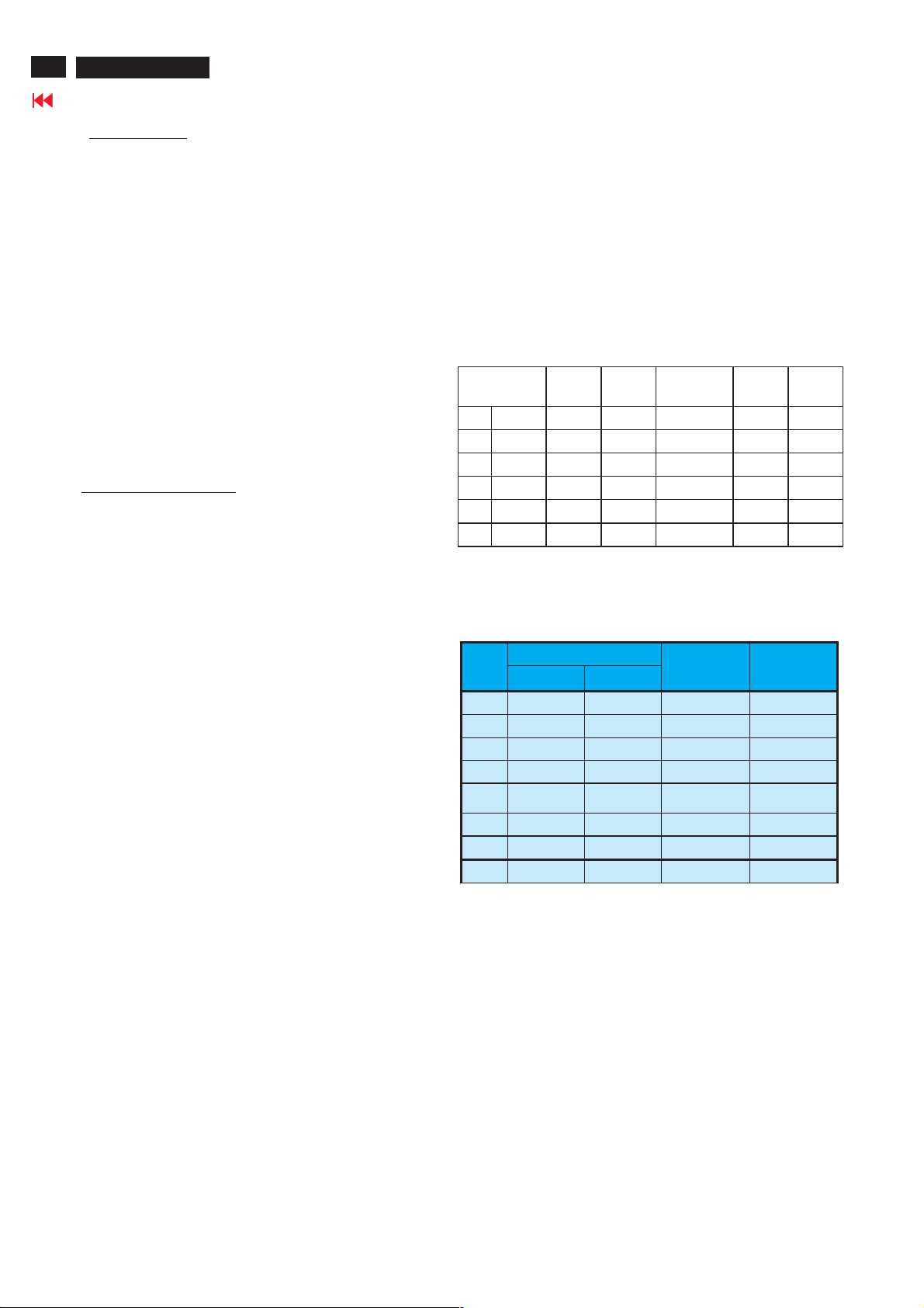
2.2 PC Inpu t signal mode
2.2.1 PRESET VIDEO RESOLUTION
The analogue color LCD monitor must be capable of displaying
standard resolutions within the vertical frequency range of
58 - 63 Hz, and horizontal scan range of 30 - 50 KHz .
Use the CHROMA-2250 generator as the standard signal timing
source.
Dot rate (MHz) H.freq
(KHz)
1 25.175 31.469 IBM VGA 640*480 59.940
2 36.000 35.156 VESA 800*600 56.250
3 40.000 37.879 VESA 800*600 60.317
4 65.000 48.363 VESA 1024*768 60.004
5 74.500 44.772 WXGA 1280*720 59.855 CVT
5 79.500 47.776 WXGA 1280*768 59.87 CVT
Resolution recommend on 1280 X 720 @ 60Hz
Mode Resolution V.freq
(Hz)
Remar k
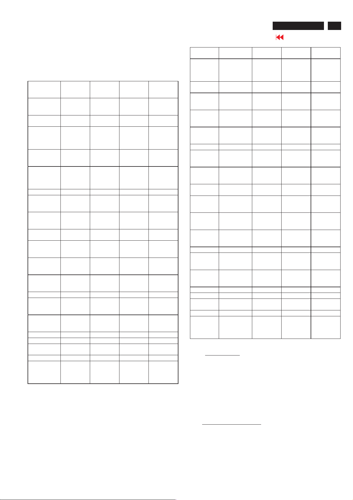
2.3 TV input signal Channel and pattern fo r NAFTA
model (Table1)
Signal Distribution Table (NTSC)
CH
A03 61.25MHz 65.75MHz NTSC M Color Circle
A06 83.25MHz 87.75MHz NTSC M Red Raster
A09 187.25MHz 191.75MHz NTSC M Circle Pattern
A11 199.25MHz 203.75MHz NTSC M Cross Hatch
A13 211.25MHz 215.75MHz NTSC M
A52 699.25MHz 703.75MHz NTSC M Color Bar
A69 801.25MHz 805.75MHz NTSC M 100% White
C70 499.25MHz 503.75MHz NTSC M Checkerboard
Table 1
Freq uenc y Carriers
Video Sound
TV System
Pattern
Two White
Window
Page 17
Electrical Instructions
26MF605W/17
Go to cover page
17
2.4 HD input mode
2.4.1 HD detail timing
(For Quantune Data setting with Q801GD or 802G in YpbPr mode)
Item
Pixel rate 74.25MHz
Horizontal
Frequency
Active 1920
Blank 280 pixels
Period 2200
Pulse delay 44 pixels
Pulse width 44 pixels
Vertical
Frequency
Active 1080 lines
Blank 45 lines
Period 1125 lines
Pulse delay 2 lines
Pulse width 5 lines
EQ before 0 line 0 line 0 line 0 line
EQ after 1 line 0 line 1 line 0 line
Scan Interlace ProgressiveInterlace Progressiv
Sync type ACS ACS ACS ACS
Video kind Analog
1920X108
0i 60Hz
(13.468
ns)
33.75KHz 45KHz 28.125KHz37.5KHz
pixels
(25.859
us)
(3.771 us)
pixels
(29.630
us)
(0.593 us)
(0.593 us)
60 Hz 60 Hz 50 Hz 50 Hz
(32.000
ms)
(1.333
ms)
(33.333
ms)
(0.059
ms)
(0.148
ms)
YPbPr
(ITU-R
BT.709)
1280X720
P 60Hz
74.25MHz
(13.468
ns)
1280
pixels
(17.239
us)
370 pixels
(4.983 us)
1650
pixels
(22.222
us)
70 pixels
(0.943 us)
40 pixels
(0.539 us)
720 lines
(16.0 ms)
30 lines
(0.667
ms)
750 lines
(16.667
ms)
5 lines
(0.111
ms )
5 lines
(0.111
ms)
Analog
YPbPr
(ITU-R
BT.709)
1920X108
0i50Hz
74.25MHz
( 13.468ns
)
1920
pixels
(25.859
us)
720 pixels
( 9.697
us )
2640
pixels
( 35.556
us )
484 pixels
( 6.519
us )
44 pixels
( 0.593
us )
1080 lines
( 38.4
ms )
45 lines
(1.6 ms )
1125 lines
(40ms)
2 lines
( 0.071
ms )
5 lines
(0.178
ms )
Analog
YPbPr
(ITU-R
BT.709 )
1280X720
P50Hz
74.25MHz
(13.468
ns)
1280
pixels
(17.239
us)
700 pixels
(9.428 us)
1980
pixels
(26.667
us)
400 pixels
(5.387 us)
40 pixels
(0.539 us)
720 lines
(19.2 ms)
30 lines
(0.8 ms)
750 lines
(20 ms)
5 lines
(0.133
ms )
5 lines
(0.133
ms)
e
Analog
YPbPr
(ITU-R
BT.709)
Item 720X576P
Pixel rate 27 MHz
Horizontal
Frequency
Active 720 pixels
Blank 144 pixels
Period 864 pixels
Pulse
delay
Pulse
width
Vertical
Frequency
Active 576 lines
Blank 49 lines
Period 625 lines
Pulse
delay
Pulse
width
EQ before 0 line 0 line 2 line 3 line
EQ after 0 line 0 line 2 line 3 line
Scan Progressive ProgressiveInterlace Interlace
Sync type ACS ACS ACS ACS
Video kind Analog
50Hz
(37.037 ns)
31.25 KHz 31.5KHz 15.625KHz15.734KH
(26.667 us)
(5.333 us)
(32.000 us)
12 pixels
(0.444 us)
64 pixels
(2.370 us)
50 Hz 60 Hz 50 Hz 59.94 Hz
(18.432 ms)
(1.568 ms )
(20.000 ms)
5 lines
(0.160 ms)
5 lines
(0.160 ms)
YPbPr
(SMP
TE RP177)
720X480P
60Hz
27.027MH
z
(37.000
ns)
720 pixels
(26.640
us)
138 pixels
(5.106 us)
858 pixels
(31.746
us)
16 pixels
(0.592 us)
62 pixels
(2.294 us)
480 lines
(15.238
ms)
45 lines
(1.429
ms)
525 lines
(16.667
ms)
9 lines
(0.287
ms)
6 lines
(0.190
ms)
Analog
YPbPr
(SMPTE
RP177)
Table 2
720X576i
50Hz
13.5MHz
( 74.074
ns )
720 pixels
(53.333
us)
144 pixels
( 10.667
us )
864 pixels
( 64.00
us )
12 pixels
( 0.889
us )
63 pixels
( 4.667
us )
576 lines
( 36.864
ms )
49 lines
(3.136
ms )
625 lines
(40ms)
2 lines
( 0.128
ms )
3 lines
(0.192
ms )
Analog
YPbPr
(SMPTE
RP177 )
720X480i
60Hz
13.5MHz
( 74.074
ns )
z
720 pixels
(53.333
us)
138 pixels
( 10.222
us )
858 pixels
( 63.556
us )
19 pixels
(1.407
us )
62 pixels
(4.593
us )
480 lines
( 30.507
ms )
45 lines
(2.860
ms )
525 lines
( 33.367
ms )
4 lines
(0.254
ms )
3 lines
(0.191
ms )
Analog
YPbPr
(SMPT
E RP177 )
3. Pow er supp ly
3.1 Setup the AC I/P at 264 VAC and 90VAC , and power board
3.2 Any adjustment is not needed.
provide two DC Output
1. The DC output voltage is 24V ± 1V DC for Inverter and
Scaler board Measured point between pin3(+24V) and
pin6(GND) at item 1001 of scaler board
2. The DC output voltage is 16V ± 1VDCforScalerand
Audio board Measured point between pin1(+16V) and
pin6(GND) at item 1001 of scaler board
4. TV Mode display adjust
4.1 White balance adjustment (B)
4.1.1 General set-up :
Equipment Requirements: Color analyzer.
Input requirements:
Input Signal Type : RF signal
1. Set to NTSC system, frequency=187.25MHZ ( for
NAFTA model ), with white pattern of 100%
Page 18
18
26MF605W/17
Go to cover page
Electrical Instructions
2. Select Smart picture to Personal mode and check the x, y data.
Input Signal Strength : 10mV (80 dBuV) terminal voltage.
Input Injection Point : TV Tuner input
Alignment method:
Initial Set-up :
1.Set TV(7119) Brightness=142; Saturate =64,
Contrast =68 in Factory mode(can be fine tuned).
2. Set Smart picture as
3. Apply 100% Full White pattern by TV pattern
generator.
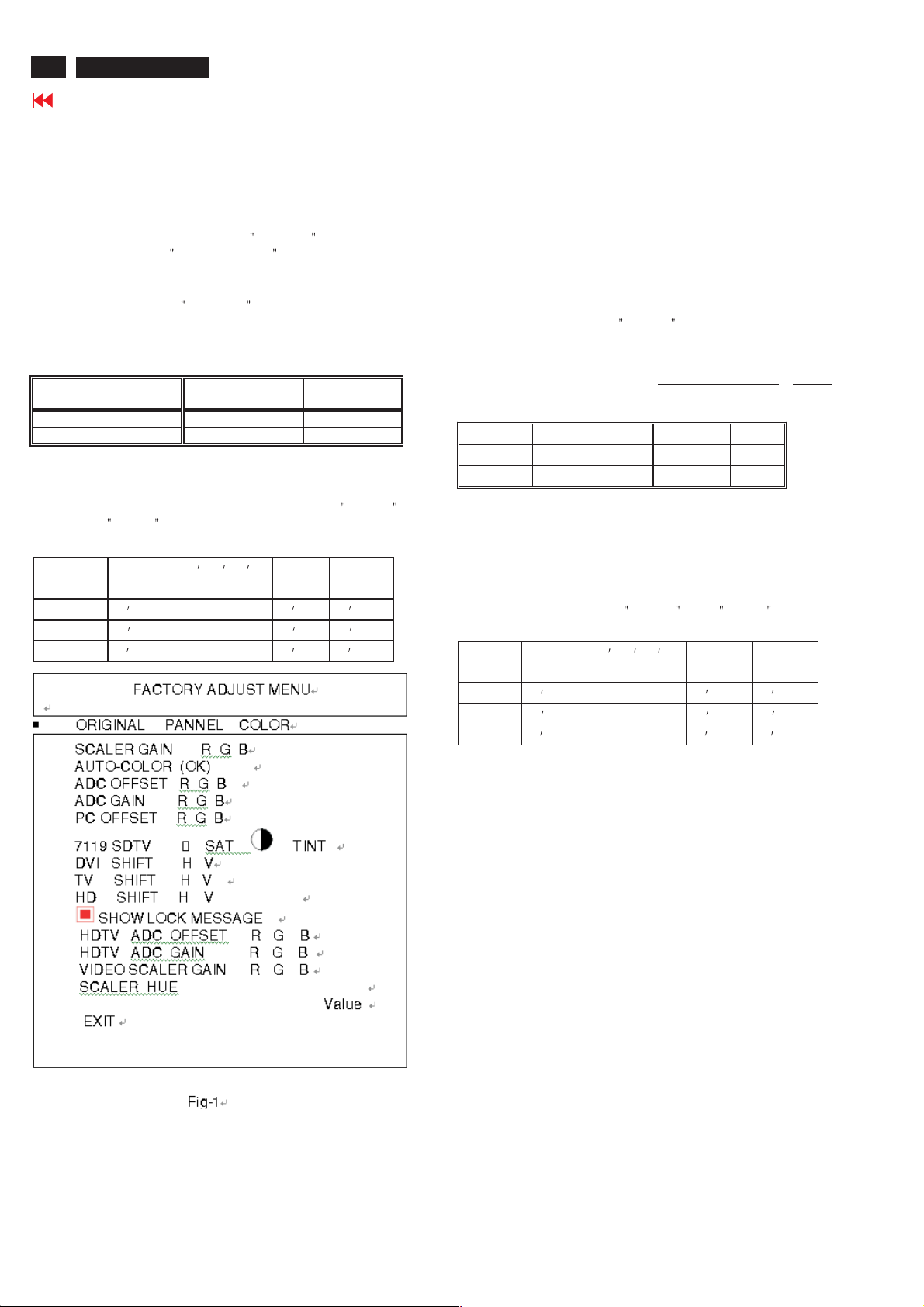
Alignment : Adjust the VIDEO SCALER GAIN RG B
Factory Mode
menu : press VOL+ and VOL- keys together around six
seconds]
1. Check (X, Y) co-ordinates as below:
Picture Mode
Normal (Original)
Table 3: Reading with Minolta CA-110.
2. Check the gray pattern should be distinguish and
color bar is correct
4.1.2 Set TV Color temperature in Factory mode as
and
COOL The VIDEO SCALER GAIN R\G\B value will be
followed below
Normal/ the R \G \B
are gain after alignment. WARM
R gain R R R -10
G gain G G -10 G -10
B gain B B -10 B
NORMAL . (See Fig 1.) [ Enter factory
0.289 ± 0.005 0.304 ± 0.005
Personal
xy
WARM ,
COOL
5. PC mode Display Adjustment
5.1 Display quality adjustment
Use timing mode as describe in 2.2, and use the POPO (pixel on pixel
off) pattern to adjust the clock until no stripe and adjust the phase until
clear picture.
Check all pre-set 6 modes.
5.2 WHITE-D ad justment (B )
in
.
5.2.1 At factory mode apply 1280X720 @60Hz mode with 32 gray
pattern.
Set smart picture at
Contrast to 50%.
Press AUTO-COLOR function for auto ADC offset and gain setup.
5.2.2 Apply full white pattern Set SCALER GAIN R G B
SCALER GAIN R G B.
1. Check (X, Y) co-ordinates as below :
Normal/ (8500°K)
x (center) 0.289 ± 0.015
y (center) 0.304 ± 0.015
Table 4: Reading with Minolta CA-110.
2. Check the gray level color poor & noise condition and chromaticity
Note: 1. Use Minolta CA-110 for color coordinates and luminance check.
2. Lumin ance> 400 cd/m
Original (NORAML)color and PC Brightness control; Contrast
control at 100%
5.2.3 Set Smart picture as
The SCALER GAIN R\G\B value will be followed below
Normal/ the R \G \B
are gain after alignment.
R gain R R R -10
G gain G G -10 G -10
B gain B B -10 B
5.3 Check th e digital in terface c able (B )
Check the 64 gray level color poor & noise condition.
Normal , and Brightness to 50% and
= VIDEO
2
in the center of the screen at
WARM , and COOL
WARM COOL
.
6. HDTV Mode display adjust
6.1 White balance adjustment (B)
General set-up:
Equipment : Quantum Data Pattern Generator 801GD or 802G.
Or FLUKE 54200, apply 576i, DIGITAL SCAN/DIGI_ADC1 pattern.
Apply 1080i, RGBW(177=Infocus2) gray pattern.
Page 19
Electrical Instructions
.
26MF605W/17
Go to cover page
19
Alignment method:
Initial Set-up: 1.Set Smart picture as
Alignments : Set HD VIDEO SCALER GAIN R\G\B= TV
Check (X, Y) co-ordinates as below:
Picture Mode x y
Personal
If chromaticity (X, Y) co-ordinates is out of specification,
re-alignment Video scalar R/G/B gain from 127/127/127.
7. Preset DVI HDCP Key
7.1 Download HDCP Key
The 284 bytes HDCP key should be download to the TV set via
IF cable using ATE at factory Alignment tools
7.2 DVI Video HDCP Key Test
7.2.1Use pattern generator
Equipment: Quantum 802R or 802BT or equivalent equipments.
Pattern : Standard HDCP Pattern (It
Timing : 720 X 480P 60Hz
Result : The PASS information should be shown on the screen.
7.2.2 Use DVD Player:
Equipment: 1.Pioneer (model: DV-S969AVi) or equivalent equipments
Result : The picture should be shown Normally.
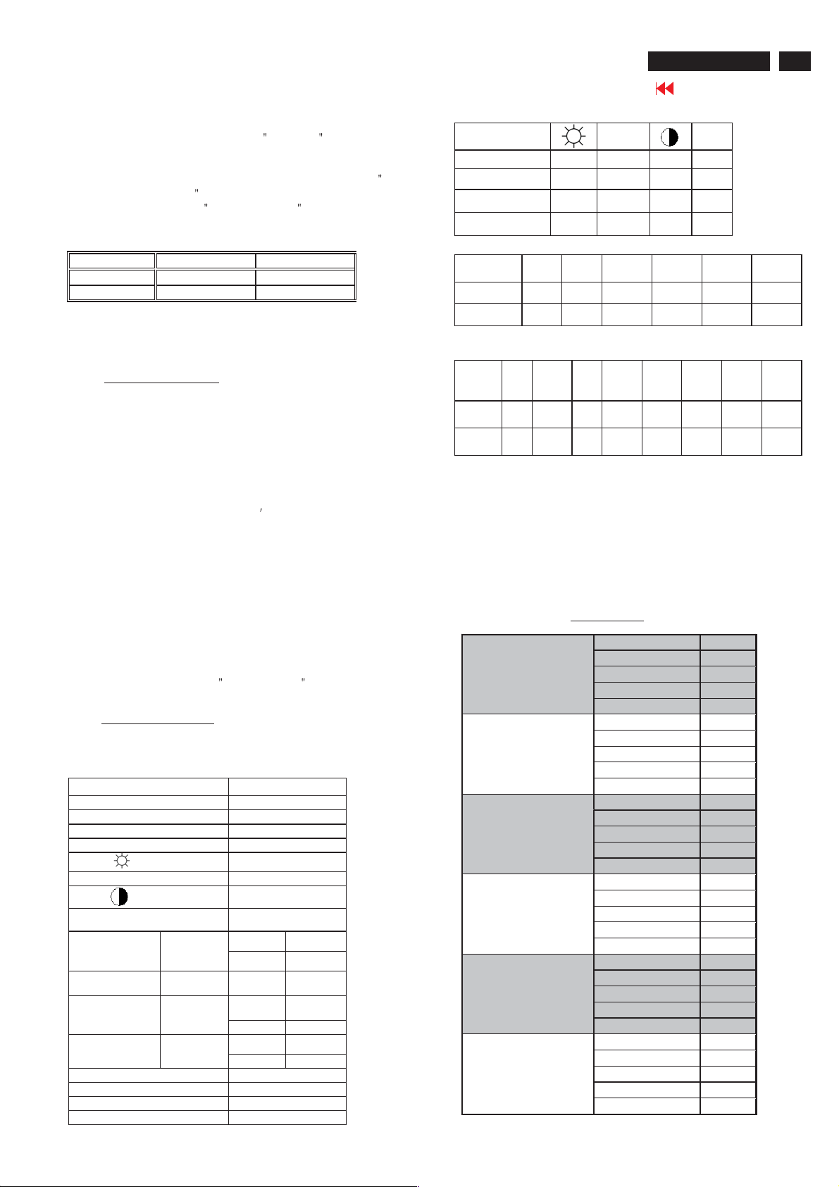
8. Preset EEPROM d ata
EEPROM data has to be preset data according following table.
8.1 Factory mo de preset .
Function
SCALER GAIN
ADC Off set R/G/B
ADC Gain R/G/B
PC OFFset R/G/B
7119 brightness
7119 Satur ation #1
7119 contrast
7119 TINT
DVI SHIFT H
DVI SHIFT V
TV sh ift H
TV sh ift V
HD SHIFT H
HD SHIFT V
HD ADC OFFs et R G B
HD ADC GAIN R G B
Video Scaler Gai n
Scaler Hue
Color=60, Contrast=65)
2.Press AUTO-COLOR process.
Normal VIDEO SCALER GAIN R G B.
1. Apply
2. Check the gray pattern should be
distinguish and color bar is correct
720 X 576P 50Hz
1280X 720P 50Hz
1280X 720P 60Hz
1920X1080i 50Hz
1920X1080i 60Hz
2.DVD disk with Macro Vision protection.
Regu lar
100% Full White pattern by Quantum
DATA 802G pattern generator.
0.289 ± 0.015 0.304 ± 0.015
Personal , Brightness=48,
s color bar)
Preset value
127 127 127
127 127 127
127 127 127
127 127 127
#1
#1
#1
#2 #2
#2 #2
NTSC PAL
175 195
15 1
#3 #3
#3 #3
127 127 127
127 127 127
127 127 127
50
#1
PERSONAL/
NORMAL
TV 139 64 60 24
AV 142 64 64 24
S-Video 142 64 64 24
Component 143 70 62 --
#2
480P576P720P/
DVI shift H 22 22 96 55 103 48
DVIshiftV445040406060
#3
480i480P576i576P720
HD
shift H155
HD
shift V
8.2 Smart picture & Smart sound:
8.2.1 Final TV mode out box setting.
Smart Picture : Sport Color Temp in Factory mode : COOL
Smart Sound : Personal
PERSONAL
MOVIES
SPORTS
WEAK SIGNAL
MULTIMEDIA
NIGHT
154 16716710814679 79
39 40 49 53 39 39 58 58
SOUND VOLUME : 10
BASE : 55
TREBLE : 55
Balance :0
Virtual SURROUND : OFF
AVL : NO
SAT. TINT
50Hz
Smart Pic ture
BRIGHTNESS 45
COLOR 50
CONTRAST 65
SHARPNESS 38
TINT 50
BRIGHTNESS 59
COLOR 60
CONTRAST 51
SHARPNESS 36
TINT 50
BRIGHTNESS 48
COLOR 65
CONTRAST 75
SHARPNESS 46
TINT 50
BRIGHTNESS 52
COLOR 60
CONTRAST 51
SHARPNESS 46
TINT 50
BRIGHTNESS 52
COLOR 60
CONTRAST 68
SHARPNESS 33
TINT 50
BRIGHTNESS 45
COLOR 50
CONTRAST 65
SHARPNESS 38
TINT 50
720P/
60Hz
P/50
Hz
720
P/60
Hz
1080i/
50Hz
1080
i/50
Hz
1080i/
60Hz
1080
i/60
Hz
Page 20
20
26MF605W/17
Go to cover page
Electrical Instructions
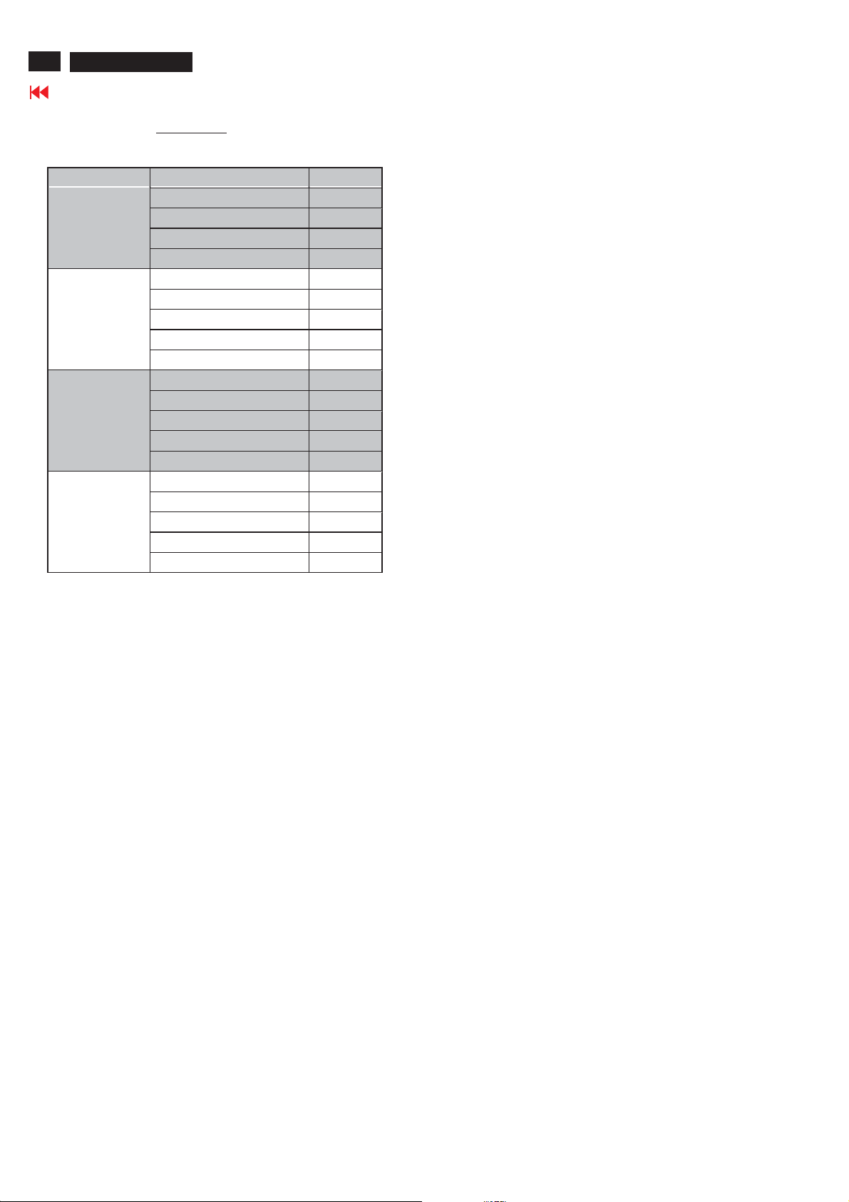
EQ Setting
PERSONAL
NEWS
MUSIC
THEATRE
Smart Sound
EQBAND1 120Hz +25
EQ BAND2 500Hz +25
EQ BAND3 1.5KHz +25
EQ BAND4 5KHz +25
EQ BAND5 10KHz +25
EQ BAND1 120Hz 0
EQ BAND2 500Hz 0
EQ BAND3 1.5KHz +20
EQ BAND4 5KHz +30
EQ BAND5 10KHz +40
EQ BAND1 120Hz +50
EQ BAND2 500Hz +35
EQ BAND3 1.5KHz +15
EQ BAND4 5KHz +30
EQ BAND5 10KHz +45
EQ BAND1 120Hz +50
EQ BAND2 500Hz +35
EQ BAND3 1.5KHz -5
EQ BAND4 5KHz +20
EQ BAND5 10KHz +40
Page 21

DDC Instructions
26MF605W/17
Go to cover page
21
General
DDC Data Re-programming
In case the DDC data memory IC or main EEPROM which storage all
factory settings were replaced due to a defect, the serial numbers have
to be re-programmed "Analog DDC IC, Digital DDC IC & EEPROM".
It is advised to re-soldered DDC IC and main EEPROM from the old
board onto the new board if circuit board have been replaced, in this case
the DDC data does not need to be re-programmed.
Additional information
Additional information about DDC (Display Data Channel) may be
obtained from Video Electronics Standards Association (VESA).
Extended Display Identification Data(EDID) information may be also
obtained from VESA.
System and equipment requirements
1. An i486 (or above) personal computer or compatible.
2. Microsoft operation system Windows 95/98 .
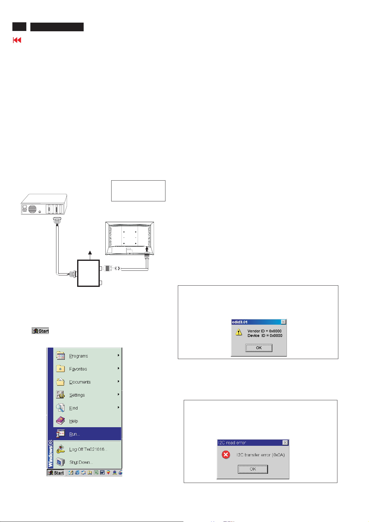
Y o Install the EDID_PORT_Tool under Win2000/XP . As
ou have t
Fig. 1 .
A. Cody the "UserPort.sys" to C:\WINNT\system32\drivers(win2000)
C:\WINDOWS\system32\drivers(winXP)
B. Running " io.exe" everytime, Before you start to programming
edid data .
Fig. 1Fig.
1
Note: The alignment box has already build-in a batteries socket for
using batteries (8~12V) as power source. Pull out the socket by
remove four screws at the rear of box. Please do not forget that
remove batteries after programming. The energy of batteries can
only drive circuits for a short period of time.
To Printer port
DC 8~12V
To Monitor
D-sub/DVI cable
Power
indicator
Fig. 3
Pin assignment
A. 15-pin D-Sub Connector
PIN No. SIGNAL
1 Red video input
2 Green video input / sync on green
3 Blue video input
4GND
5 GND - Cable detect
6RedvideoGND
7 Green video GND
8 Blue video GND
9DDC+3.3Vor+5V
10 Logic GND
11 GND
12 Serial data line (SDA)
13 H-sync / H+V
14 V-sync
15 Data clock line (SCL)
B. Input DVI -D Connector pin
3. EDID46.EXE program
4. A/D Alignment kits (12NC: 3138 106 10079):
inclusion : a. Alignment box x1 (Fig. 2)
b. Printer cable x1
c. (D-Sub) to (D-Sub) cable x1
D. (D-Sub) to (DVI) cable x1
Fig. 2
Pin No. Description
1 T.M.D.S. data2-
2 T.M.D.S. data2+
3 T.M.D.S. data2 shield
4 No Connect
5 No Connect
6 DDC clock
7 DDC data
8 No Connect
9 T.M.D.S. data1-
10 T.M.D.S. data1+
11 T.M.D.S. data1 shield
12 No Connect
13 No Connect
14 +5V Power
15 Ground (for +5V) - Cable detect
16 Hot plug detect
17 T.M.D.S. data0-
18 T.M.D.S. data0+
19 T.M.D.S. data0 shield
20 No Connect
21 No Connect
22 T.M.D.S clock shield
23 T.M.D.S. clock+
24 T.M.D.S. clock-
Page 22
22
26MF605W/17
Go to cover page
DDC Instructions
Configuration and procedure
There is no Hardware DDC (DDC IC) anymore. Main EEPROM stores
all factory settings and DDC data (EDID code) which is also called
Software DDC. The following section describes the connection and
procedure for Software DDC application. The main EEPROM can be reprogrammed by enabling '' factory memory data write'' function on the
DDC program (EDID46.EXE).
Initialize alignment box
In order to avoid that monitor entering power saving mode due
to sync will cut off by alignment box, it is necessary to initialize
alignment box before running programming software
(EDID46.EXE). Following steps show you the procedures and
connection.
Step 1: Supply 8-12V DC power source to the Alignment box by
plugging a DC power cord .
Step 2: Connecting printer cable and D-Sub cable of monitor as Fig. 4
PC
1= Power connector
2= D-SUB connector
3. At the submenu, type the letter of your computer's hard disk drive
followed by :EDID46 (for example, C:\EDID46, as shown in Fig. 6).
1
Fig. 6
4. Click OK button. The main menu appears (as shown in Fig. 7).
This is for initialize alignment box.
DC Power
8-12 V
Fig. 5
----->
2
----->
To printer port (LTP1)
Step 3: Installation of EDID46.EXE
Method 1: Start on DDC program
Start Microsoft Windows.
1. The Program"EDID46.EXE" in service manual cd-rom be copyed to C:\ .
2. Click , choose Run at start menu of Windows as shown
In Fig. 5.
Printer
Port
To
Monitor
To PC
1
Fig. 4
Fig. 7
Note 1: If the connection is improper, you will see the following error
message (as shown in Fig. 8) before entering the main menu.
Meanwhile, the (read EDID) function will be disable. At this
time, please make sure all cables are connected correctly and
fixedly, and the procedure has been performed properly.
Fig. 8
Note 2: During the loading, EDID46 will verify the EDID data which just
loaded from monitor before proceed any further function, once
the data structure of EDID can not be recognized, the following
error message will appear on the screen as below. Please
confirm following steps to avoid this message.
1. The data structure of EDID was incorrect.
2. DDC IC that you are trying to load data is empty.
3. Wrong communication channel has set at configuration setup
windows.
4. Cables loosed or poor contact of connection.
Fig. 9
Page 23
DDC Instructions
Re-programming Analog DDC IC
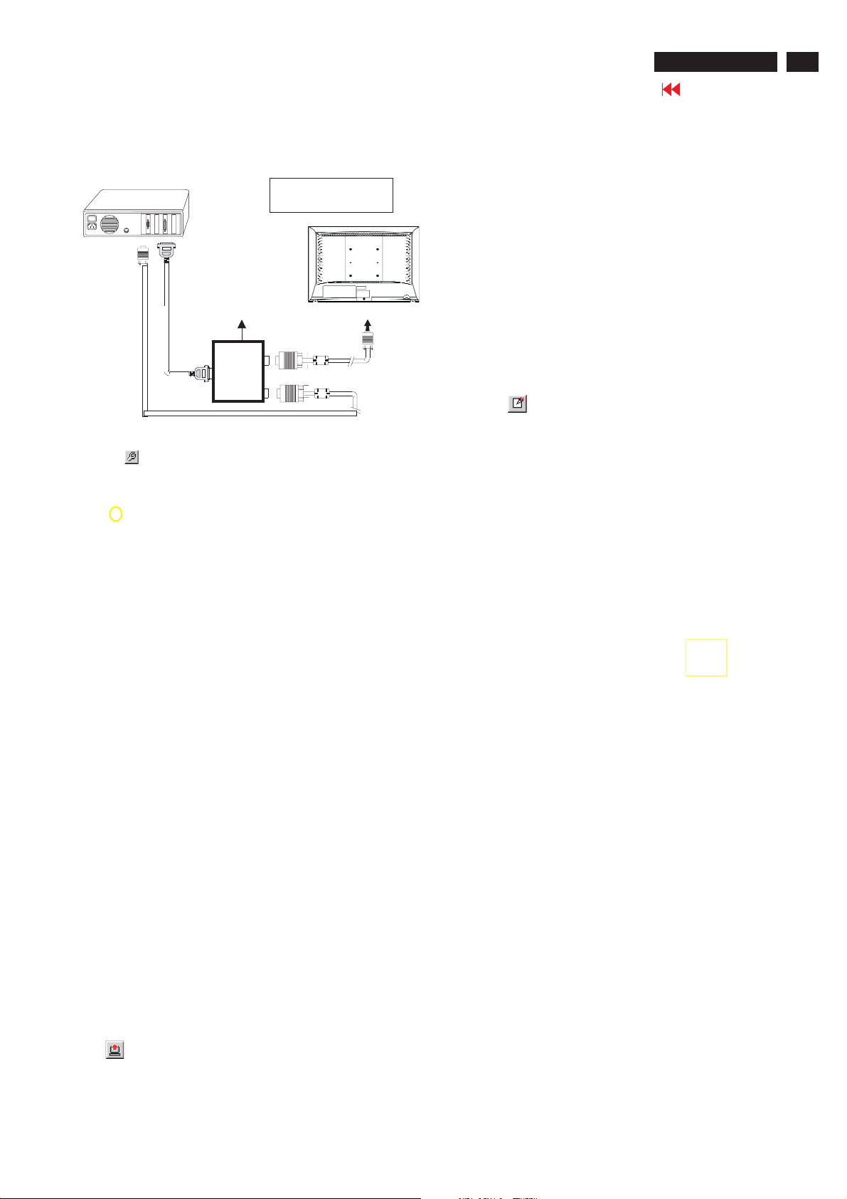
Step 1: After initialize alignment box, connecting all
cables and box as shown in Fig. 10.
PC
1=Power connector
2= D-SUB connector
26MF605W/17
Go to cover page
23
DC Power
8-12V
To printer port (LTP1)
To PC Video port (D-sub)
Printer
Port
To
Monitor
To PC
1
2
----->
----->
Step 2: Read DDC data from monitor
1. Click icon as shown in Fig. 11 from the tool bar to bring up
the Channels "Configuration Setup" windows as shown in Fig. 11.
=====>
Click this button
Fig. 11
2. Select the DDC2Bi as the communication channel.
As shown in Fig. 12.
Fig. 10
Fig. 13
Step 3: Modify DDC data (verify EDID version, week,
year)
Click (new function) icon from the tool bar, bring up
Step 1 of 9 as shown in Fig. 14 .
EDID46 DDC application provides the function selection and
Select and fill out,
If necessary.
Fig. 14
Fig. 12
3. Click OK button to confirm your selection.
4. Click icon (Read EDID function) to read DDC EDID data from
monitor. The EDID codes will display on screen as shown in Fig. 13.
Step 4: Modify DDC data (Monitor Serial No.)
1. Click Next , bring up Fig. 15.
Fig. 15
Page 24

24
26MF605W/17
Go to cover page
DDC Instructions
2. Click Next , bring up Fig.16.
3. Click Next , bring up Fig.17.
5. Click Next , bring up Fig.19.
Fig. 19
Fig. 16
6. Click Next , bring up Fig. 20.
In this step, please confirm the Descriptor Data Type is
Monitor Range Limits, and all the items are same as below.
4. Click Next , bring up Fig.18.
Fig. 17
Fig. 18
Fig. 20
7. Click Next , bring up Fig. 21.
Fig. 21
Page 25
DDC Instructions
8. Click Next , bring up Fig. 22.
- Click Finish to exit the Step window.
- Serial number can be filled up at this moment (for example,
26MF605002).
NOTE: You must modify the Serial NO. In step 9, otherwise the Serial NO.
In OSDCouldn't be modified correctly.
Fig. 22
26MF605W/17
25
Go to cover page
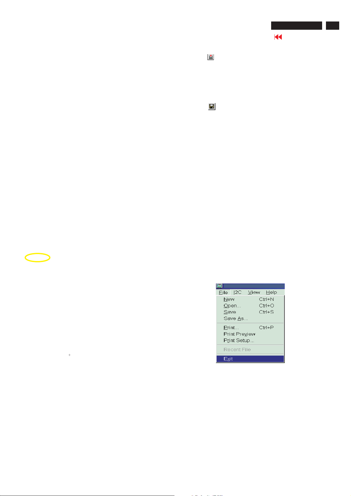
4). Click (Write EDID) icon from the tool bar to write DDC data. then
the screen will be black for 2-3 seconds,then the screen recovers,
and "ATTENTION NO VIDEO INPUT"will come on the screen of the
monitor,wait for 20-30 seconds ,DDC data will be finished Writing.
Step 6: Save DDC data
Sometimes, you may need to save DDC data as a text file
for using in other IC chip. To save DDC data, follow the
steps below:
1. Click (Save) icon (or click "file"-> "save as") from the tool
bar and give a file name as shown in Fig. 25.
The file type is EDID46 file (*.ddc) which can be open in
WordPad. By using WordPad, the texts of DDC data & table
(128 bytes, hex code) can be modified. If DDC TEXTS &
HEX Table ar completely correct, it can be saved as .ddc flie
to re-load it into DDC IC for DDC Data application.
Step 5: Write DDC data
1. Configuration should be as Fig. 23. And press OK.
2. Access Factory Mode
1). Turn off monitor.
2). Press power "Power " button.Then quickly push"Volume -"
and " Volume ",and hold this two buttons,then the screen
comes out "Waiting For Automatic Adjustment ",then the screen
will be black for one second ,untill comes out "Windows screen"]
=> then release this two buttons, then press "Menu"button, wait
until the OSD menu with Characters "F1/FL1 NAFTA V0.91.1
041124ADJUST" (below OSD menu) come on the Screen of the
monitor (see Fig. 24).
Fig. 23
Fig. 25
2. Click Save.
Step 7: Exit DDC program
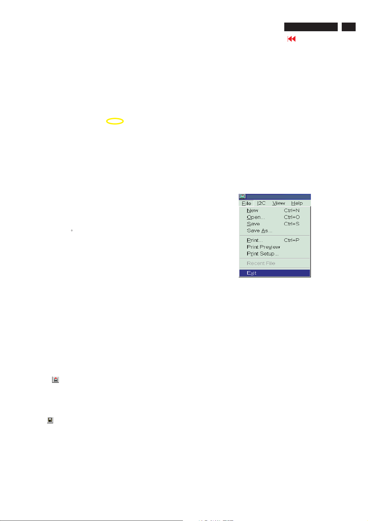
Pull down the File menu and select Exit as shown in Fig. 26.
Fig. 26
Step 8: Turn off the monitor, exit the factory mode.
3) Push Menu to exit OSDmenu.""
Fig. 24
----------------->
Factory Mode
Indicator
Page 26
26
26MF605W/17
Go to cover page
Re-programming Digital DDC IC
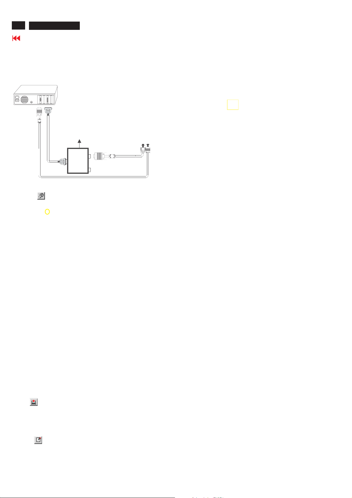
Step 1: After initialize alignment box, connecting all
cables and box as shown in Fig. 27.
PC
1=DVI-D connector
2=D-sub connector
3=Power Plug
DDC Instructions
Select and fill out,
If necessary.
DC Power
~
8 12V
To video card
To printer port (LTP1)
Printer
Port
D-sub to DVI-D cable
To
Monitor
Step 2: Read DDC data from monitor
D-sub cable
3
1
2
Fig. 27
1. Click icon as shown in Fig. 11 from the tool bar to bring up
the Channels "Configuration Setup" windows as shown in Fig. 28.
=====>
Click this button
Fig. 28
2. Select the DDC2Bi as the communication channel.
As shown in Fig. 29.
Fig. 31
Step 4: Modify DDC data (Monitor Serial No.)
1. Click Next , bring up Fig. 32.
2. Click Next , bring up Fig. 33.
3. Click Next , bring up Fig. 34.
Fig. 33
4. Click Next , bring up Fig. 35.
5. Click Next , bring up Fig. 36.
Fig. 34
Fig. 32
Fig. 29
Fig. 30
3. Click OK button to confirm your selection.
4. Click icon (Read EDID function) to read DDC EDID data from
monitor. The EDID codes will display on screen as shown in Fig. 30.
Step 3: Modify DDC data (verify EDID version, week,
year)
Click (new function) icon from the tool bar, bring up
Step 1 of 9 as shown in Fig. 31 .
EDID46 DDC application provides the function selection and
text change (select & fill out) from Step 1 to Step 9.
Fig. 35
6. Click Next , bring up Fig. 37.
In this step, please confirm the Descriptor Data Type is
Monitor Range Limits, and all the items are same as below.
7. Click Next , bring up Fig. 38.
Fig. 37
Fig. 36
Fig. 38
Page 27
DDC Instructions
8. Click Next , bring up Fig. 39.
- Click Finish to exit the Step window.
- Serial number can be filled up at this moment (for example,
26MF605002).
NOTE: You must modify the Serial NO. In step 9, otherwise the Serial
NO. In OSD Couldn't be modified correctly.
26MF605W/17
Go to cover page
27
Fig. 39
Fig. 40
Step 5: Write DDC data
1. Configuration should be as Fig. 40. And press OK.
2. Access Factory Mode
1). Turn off monitor.
2). Press power "Power " button.Then quickly push " Volume -"
and " Volume ",and hold this two buttons,then the screen
comes out "Waiting For Automatic Adjustment ",then the screen
will be black for one second ,untill comes out "Windows screen"]
=> then release this two buttons, then press "Menu" button, wait
until the OSD menu with Characters "F1/FL1 NAFTA V0.91.1
041124ADJUST" (below OSD menu) come on the Screen of the
monitor (see Fig. 41).
----------------->
Factory Mode
2. Click Save.
Fig.42
Step 7: Exit DDC program
Pull down the File menu and select Exit as shown in Fig. 43.
Fig. 43
Step 8: Turn off the monitor, exit the factory mode.
Indicator
Fig. 41
3) Push Menu to exit OSD menu.""
3. Click (Write EDID) icon from the tool bar to write DDC data.
Then wait for 20-30 seconds ,DDC data will be finished Writing.
Step 6: Save DDC data
Sometimes, you may need to save DDC data as a text file for using
in other IC chip. To save DDC data, follow the steps below:
1. Click (Save) icon (or click "file"-> "save as") from the tool bar and
give a file name as shown in Fig. 42.
The file type is EDID46 file (*.ddc) which can be open in WordPad. By
using WordPad, the texts of DDC data & table (128 bytes, hex
code) can be modified. If DDC TEXTS & HEX Table ar completely
correct, it can be saved as *.ddc flie to re-load it into DDC IC for DDC
Data application.
Page 28
28
26MF605W/17
Failure Mode Of Panel
Go to cover page
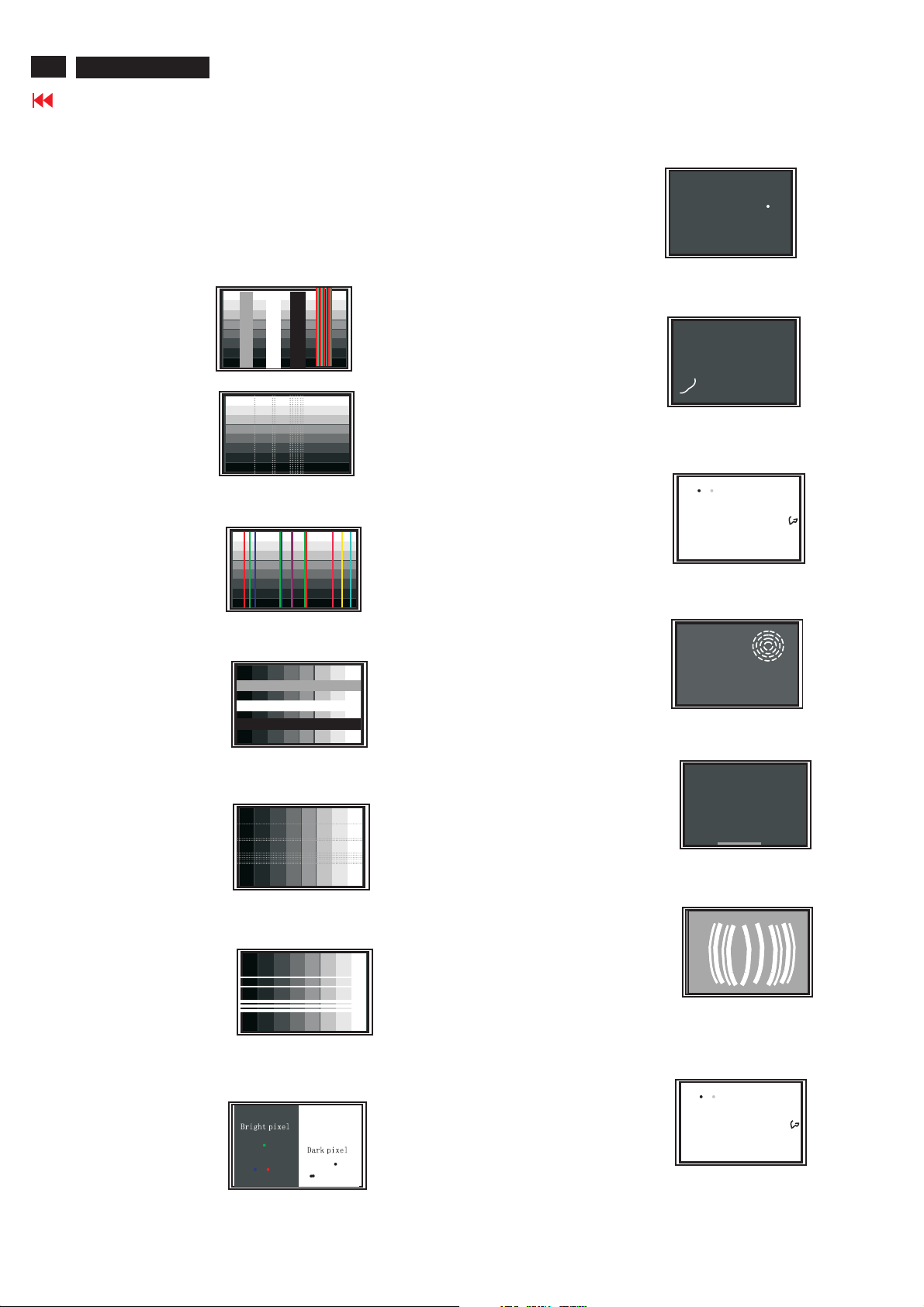
Quick reference for failure mode of LCD panel
this page presents problems that could be made by LCD panel.
It is not necessary to repair circuit board. Simply follow the mechanical
instruction on this manual to eliminate failure by replace LCD panel.
Polarizer has bubbles
Failure description
Vertical block defect
Vertical dim lines
Vertical lines defect
(Always bright or dark)
Horizontal block defect
Phenomenon
Polarizer has bubbles
Foreign material inside
polarizer. It shows liner or
dot shape.
Concentric circle formed
Horizontal dim lines
Horizontal lines defect
(Always bright or dark)
Has bright or dark pixel
Bottom back light of LCD is
brighter than normal
Back light un-uniformity
Backlight has foreign material.
Black or white color, liner or
circular type
Page 29
SafetyTest Requirements
26MF605W/17
Go to cover page
29
All units that are returnedfor service or repair mustpass the
originalmanufacturessafety tests. Safety testingrequiresboth
and testing.Hipot Ground Continuity
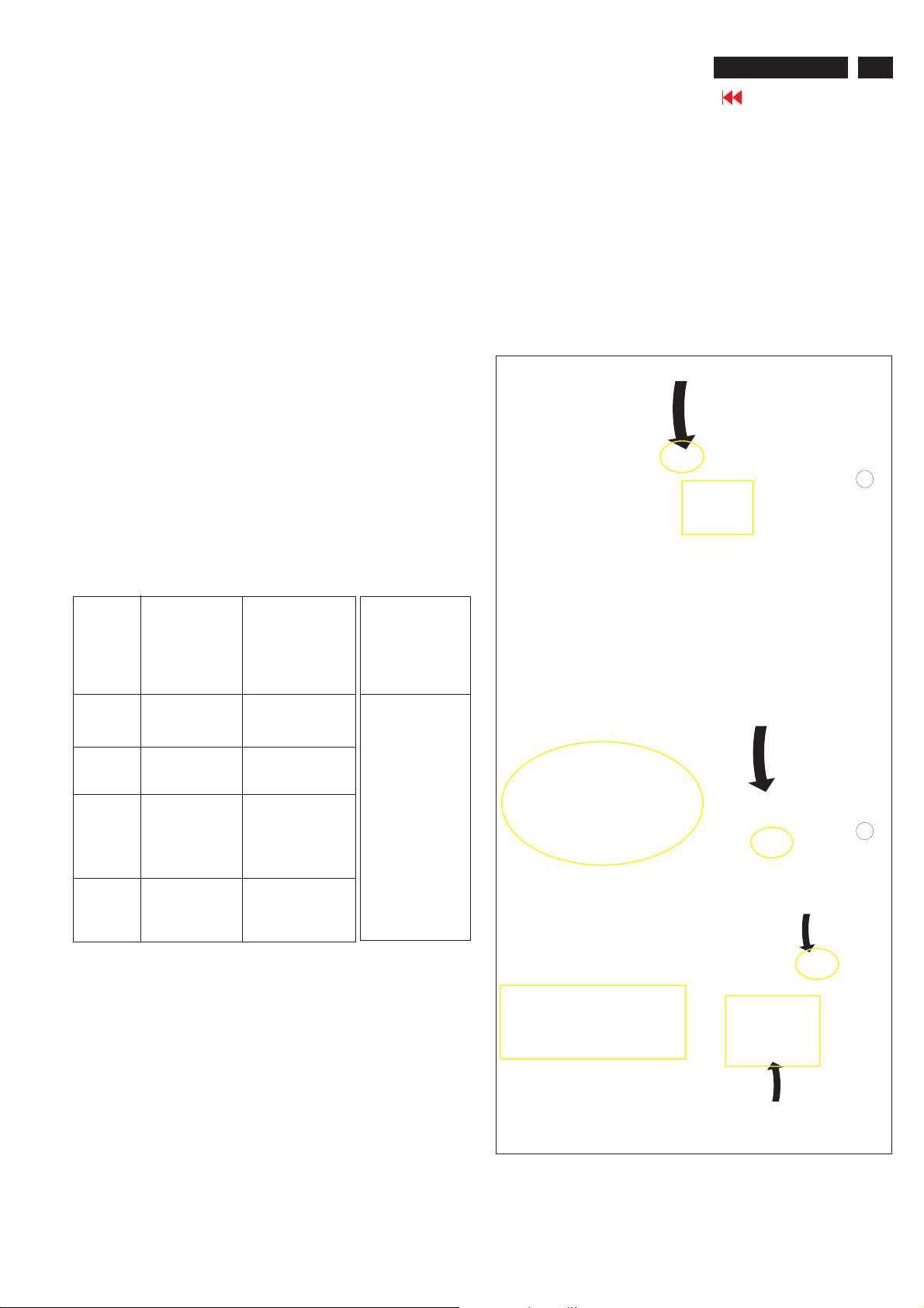
HI-POT TEST INSTRUCTION
1.Application requirements
1.1 All mains operated products mustpass the Hi-Pot testas
describedinthis instruction.
1.2 This test must be performed again after thecovershave
been refittedfollowingthe repair, inspection or modification
of theproduct.
2.
Test method
2.1 Connectingc
2.1.1 Thetest specified must be appliedbetween the parallel-
bladeplugof the mainscord and all accessible metal
parts of theproduct.
2.1.2 Before carryingoutthetest, reliableconductive
connections
maintained throughoutthetest period.
2.1.3 The mains switch(es) must be in the "ON" position.
2.2 Test Requirements
All productsshould be HiPot and Ground Continuity tested as
follows:
onditions
must beensured and thereafter be
3. Equipments and Connection
3.1. Equipments
For example :
-ChenHwa9032 PROGRAMMABLE AUTO SAFETY
TESTER
-ChenHwa 510BDigital Grounding ContinuityTester
-ChenHwa 901 (AC Hi-pot test), 902 (AC, DC Hi-pot test)
Withstanding Tester
3.2.Connection
*Turn on thepower switch ofmonitor before Hipot and
Ground Continuity testing.
Clip
Clip
Condition HiPot Test for HiPot Test for Ground Continuity
voltage (2000VAC) (1200VAC) 25A,AC
Testtime 3seconds 1 second 3 seconds(min.)
(min.) Resistance
Trip set at 100 uA 5 mA <=0.09+Rohm,
current for Max. R is the
(Tester)
Ramp set at 2
time seconds
(Tester)
2.2.1 The minimum test durationfor QualityControlInspector
2.2.2 Thetestvoltage must be maintainedwithin the specified
productswhere productswhere Testrequirement
the mains inputthe mains input is
range is Full 110V AC(USA
range(or 220V type)
AC)
Test2820VDC 1700VDC
limitation; set resistance of
at 0.1 uA for the mains cord.
Min. Limitation
must be1minute.
voltage + 5%.
Testcurrent:
Testtime:
required:
(ChenHwa 9032 tester)
Video cable
Connect the "video cable"
or "grounding screw"
to the CLIP on your tester.
Grounding screw
Connect the power cord
to the monitor.
2.2.3 There must be no breakdown duringthetest.
2.2.4 Thegrounding bladeo
conductedwith accessible metal parts.
rpin ofmains plug must be
Power outlet
4. Recording
Hipot and Ground Continuity testing records have to be kept
for a period of 10 years.
(Rear view of monitor)
Page 30
30
26MF605W/17
ISP Instructions
Go to cover page
Configuration and procedure
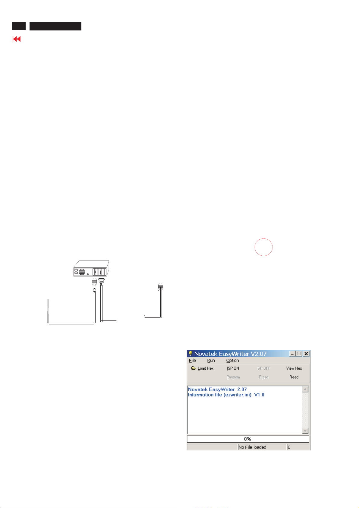
"Easywriter " The software is providedbyNovatek to upgradethe
firmware of CPU.
It is a windows-based program, which cannot be run in MS-DOS.
DDC2BI_ISP TOOL (3138 106 10396) is for the interface between
"Parallel Port of PC" and "15 pin-D-SUB connector of Monitor".
System and equipment requirements
1. An i486 (or above) personal computer or compatible.
2. Microsoft operation system Windows 95/98/2000/XP.
3. ISP Software " Easywriter "
4. as showninFig. 1
DDC2BI_ISP TOOL (3138 106 10396)
D-SUB to monitor
Step 3 :Copy the FL1_NAFTA_26_V120_3A10.hex to C:\26MF605W-17
as shown in Fig. 4 .
Lenovo CK5S5
ParallelPorttoPrintPortinPC
Fig. 1
5. Connect and Mains cord to Monitor as shown
in Fig. 2.
Connect to
Mains cord
6. Install and setup the Easywriter program
DDC2BI_ISP TOOL
Monitor (A)
Video cable
Fig.2
PC
To v i deo card
26MF605W-17 -Monitor (B)
D-Sub
Connect to Mains
cord at this moment.
ISP box
To printer port (LTP1)
------------------------------->
Fig.4
Update the firmware
1.Doubleclick the Easywriter.exeiconindesktop then appears
window as showninFig.6 .
Fig. 5
Step1:Makeafolder in your PC as showninFig. 3.
Step 2 : Copy ISP Software Easywriter into your folder
For example : C:\
as showni
nFig.3.
170S5
26MF605W-17
Fig. 3
Fig. 6
Page 31
ISP Instructions
26MF605W/17
Go to cover page
31
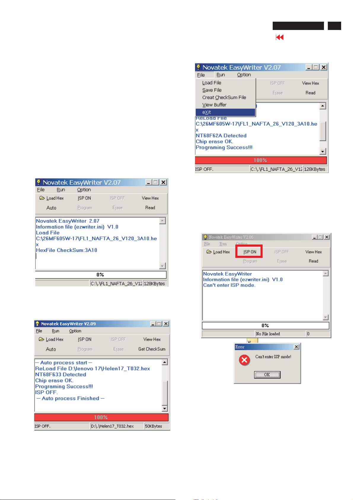
2. Press the Load hex then select the FL1_NAFTA_26_V120_3A10
As shown in Fig. 7.
CK5S5
313811707211_141_94C8
Fig. 7
3. Press the AUTO to running program , the firmware be updated
as shown in Fig. 8~9.
4. Press the file --> exit to end program , as shown in Fig. 10.
Fig. 10
If there is a warring message coming as shown in Fig 11. , you
have to check the AC power, Video cable, or Novatek MCU.
Fig. 8
Fig. 9
2.07
Fig. 11
Page 32

32
26MF605W/17
ISP Instructions
Go to cover page
6. Check the firmware version
1). Turn off monitor.
2). Press power "Power " button.Then quickly push " Volume -" and "
Volume ",and hold this two buttons,then the screen comes out
"Waiting For Automatic Adjustment ",then the screen will be black
for one second ,untill comes out "Windows screen"] => then release
this two buttons, then press "Menu" button, wait until the OSD
menu You will find, after upgrade, the version have already
changed from The former "F1/FL1 NAFTA V0.91.1
041124ADJUST" to the Present "F1/FL1 NAFTA V1.20.1 050120
Lg26 LC260WX2" as shown in Fig. 12 and Fig. 13.
Before upgrade
Factory
Mode--------
Indicator
Fig. 12
After upgrade
Factory
Mode-------Indicator
Fig. 13
3) Turn off the monitor, exit the factory mode.
Page 33
Repair Tips
26MF605W/17
Go to cover page
33
0. Warning
All ICs and many other semi-conductors are susceptible to
electrostatic discharges (ESD). Careless handling during
repair can reduce life drastically. When repairing, make sure
that you are connected with the same potential as the mass
of the unit via a wrist wrap with resistance. Keep components
and tools also at the same potential !
1. Servicing of SMDs (Surface Mounted Devices)
1.1 General cautions on handling and storage
- Oxidation on the terminals of SMDs results in poor soldering.
Do not handle SMDs with bare hands.
- Avoid using storage places that are sensitive to oxidation
such as places with sulphur or chlorine gas, direct sunlight,
high temperatures or a high degree of humidity. The
capacitance or resistance value of the SMDs may be
affected by this.
- Rough handling of circuit boards containing SMDs may
cause damage to the components as well as the circuit
boards. Circuit boards containing SMDs should never be
bent or flexed. Different circuit board materials expand and
contract at different rates when heated or cooled and the
components and/or solder connections may be damaged
due to the stress. Never rub or scrape chip components as
this may cause the value of the component to change.
Similarly, do not slide the circuit board across any surface.
1.2 Removal of SMDs
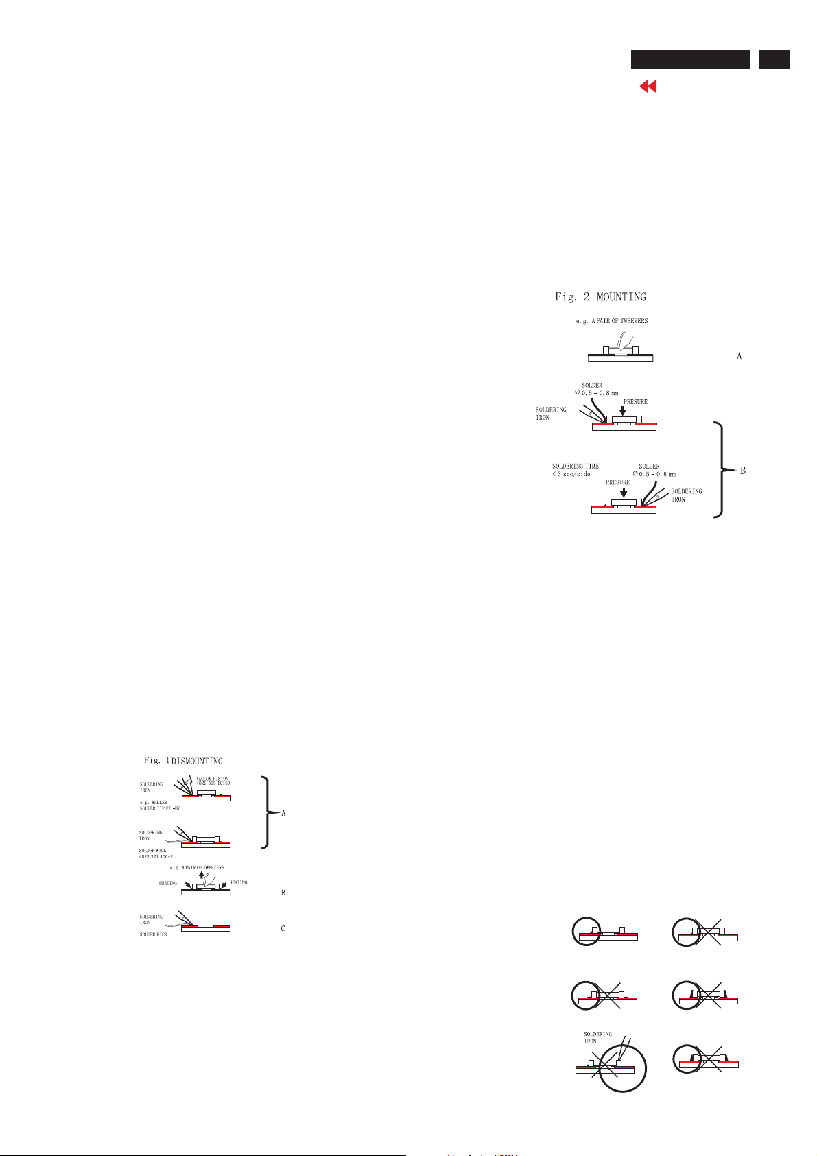
- Heat the solder (for 2-3 seconds) at each terminal of the
chip. By means of litz wire and a slight horizontal force,
small components can be removed with the soldering iron.
They can also be removed with a solder sucker (see Fig.
1A)
preferably be equipped with a thermal control (soldering
temperature: 225 to 250 C).
- The chip, once removed, must never be reused.
1.4 Attachment of SMDs
- Locate the SMD on the solder lands by means of tweezers
and solder the component on one side. Ensure that the
component is positioned correctly on the solder lands (see Fig.2A).
- Next complete the soldering of the terminals of the
component (see Fiq. 2B).
2. Caution when attaching SMDs
- When soldering the SMD terminals, do not touch them
directly with the soldering iron. The soldering should be
done as quickly as possible, care must be taken to avoid
damage to the terminals of the SMDs themselves.
- Keep the SMD's body in contact with the printed board when
soldering.
- The soldering iron to be used (approx. 30 W ) should
preferably be equipped with a thermal control (soldering
temperature: 225 to 250 C).
- Soldering should not be done outside the solder land.
- Soldering flux (of rosin) may be used, but should not be
acidic.
- After soldering, let the SMD cool down gradually at room
temperature.
- The quantity of solder must be proportional to the size of the
solder land. If the quantity is too great, the SMD might
crack or the solder lands might be torn loose from the
printed board (see Fig. 3).
While holding the SMD with a pair of tweezers, take it off gently using the
soldering iron's heat applied to each terminal (see Fig. 1 B).
- Remove the excess solder on the solder lands by means of
litz wire or a solder sucker (see Fig. 1C).
1.3 Caution on removal
- When handling the soldering.iron. use suitable pressure and be careful.
- When removing the chip, do not use undue force with the pair of tweezers.
- The soldering iron to be used (approx. 30 W) should
Right
Fig.3 Examples
Page 34

34
26MF605W/17
Repair Tips
Go to cover page
3. Lead-free product identification
You can identify lead-free product by Philips-lead-free logo on PCB.
4. Lead-free product repair instruction
4.1 Use only lead-free Solder Alloy 0622 149 00106(1.2mm SAC305) or 0622 14900108(1.0mm SAC305).
Remark: For lead free soldering material, please visit website for details. This is recommended by Philips.
4.2 Use only adequate solder tools applicable for lead-free soldering-tin. The solder tool must be able to reach at least a
solder-temperature of 400 , to stabilize the adjusted temperature at the solder-tip and to exchange solder-tips for different applications.
Small Passives/Actives to be removed with thermal tweezers
Automated system for IC and BGA repair (Microscope, Camera, Beam split optics, Computer, Programmer, Heat controllers, Vacuum
system, Laser pointer) Solder Hand-Tool (Adjustable in temperature height, Temperature shall be held constant,Flexible tips)
4.3 Adjust your solder tool so that a temperature around 360 -380 is reached and stabilized at the solder joint.
Heating-time of the solder-joint should not exceed~4sec.Avoid temperatures above 400 otherwise wear-out of tips will rise drastically
and flux-fluid will be destroyed.Corrosion of Tool-Spikes can be avoided when using SAC305 and a temperature of less than 400 .
4.4 Mix of lead-free solder-tin/parts with leaded soldering-tin/parts is possible but not recommended. If not to avoid clean carefully the
solder-joint from old tin and re-solder with new tin.
4.5 Use only original spare-parts listed in the Service-Manuals. Standard-material(consumables) can also be purchased at external
companies.
www.alphametals.com
4.6 Special information for lead-free BGA-ICs: this ICs will be delivered in so-called dry-packaging to protect the IC against moisture and
with lead-free logo on it. This packaging may only be opened shortly before it is used (soldered). Otherwise the body of the IC gets wet
inside and during the heating time the structure of the IC will be destroyed due to high (steam-)pressure. If the packaging was opened
before usage the IC has to be heated up for some hours (around 90 ) for drying (Take attention for ESD-protection!)
5. Rework on BGA (Ball Grid Array) ICs
General
Although (LF)BGA assembly yields are very high, there may still be a requirement for component rework. By rework, we
mean the process of removing the component from the PWB and replacing it with a new component. If an (LF)BGA is
removed from a PWB, the solder balls of the component are deformed drastically so the removed (LF)BGA has to be
discarded.
Device Removal
As is the case with any component that, it is essential when removing an (LF)BGA, the board, tracks, solder lands, or
surrounding components are not damaged. To remove an (LF)BGA, the board must be uniformly heated to a temperature
close to the reflow soldering temperature. A uniform temperature reduces the chance of warping the PWB.
To do this, we recommend that the board is heated until it is certain that all the joints are molten. Then carefully pull the
component off the board with a vacuum nozzle. For the appropriate temperature profiles, see the IC data sheet.
Area Preparation
When the component has been removed, the vacant IC area must be cleaned before replacing the (LF)BGA.
Removing an IC often leaves varying amounts of solder on the mounting lands. This excessive solder can be removed with
either a solder sucker or solder wick. The remaining flux can be removed with a brush and cleaning agent. After the board
is properly cleaned and inspected, apply flux on the solder lands and on the connection balls of the(LF)BGA
Note: Do not apply solder paste, as this has shown to result in problems during re-soldering.
Device Replacement
The last step in the repair process is to solder the new component on the board. Ideally, the (LF)BGAshould be
aligned under a microscope or magnifying glass. If this is not possible, try to align the (LF)BGA with any board markers.
To reflow the solder, apply a temperature profile according to the IC data sheet. So as not to damage neighbouring
components, it may be necessary to reduce some tempera
More Information
For more information on how to handle BGA devices, visit this URL: http://www.atyourservice.ce.philips.com (needs
subscription). After login, select Magazine , then go to Workshop Information . Here you will find Information on how
.to deal with BGA-ICs.
Page 35
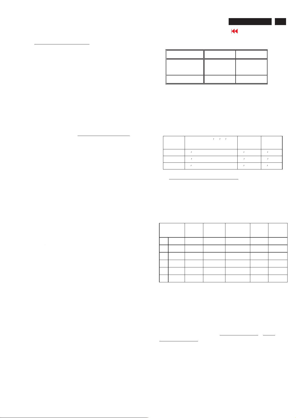
Color Adjustment
26MF605W/17
Go to cover page
35
1. TV Mode display adjust
1.1 Whi te balance adjus tment (B)
1.1.1 General set-up :
Equipment Requirements: Color analyzer.
Input requirements:
Input Signal Type : RF signal
1. Set to NTSC system, frequency=187.25MHZ ( for NAFTA
model ), with white pattern of 100%
2. Select Smart picture to Personal mode and check the x, y data.
Input Signal Strength : 10mV (80 dBuV) terminal voltage.
Alignment method:
Alignment : Adjust the VIDEO SCALER GAIN RG B
Mode "NORMAL". (See Fig 1.)
Factory
Mode--------
Indicator
Use the CHNNEL- and CHNNEL+ to select the "F1/FL1
NAFTAV0.91.1 041124 ADJUST" and then press the "VOL +" button
Input Injection Point : TV Tuner input
Initial Set-up:
1. Set TV(7119) Brightness=142; Saturate =64, Contrast =68
in Factory mode(can be fine tuned).
2. Set Smart picture as "Personal"
3. Apply "100% Full White" pattern by TV pattern generator.
in Factory
[ Enter factory menu :
1]. Turn off monitor.
2). Press power "Power " button.Then quickly push " Volume -"
and " Volume +",and hold this two buttons,then the screen comes
out "Waiting For Automatic Adjustment ",then the screen will be
black for one second ,untill comes out "Windows screen"] => then
release this two buttons, then press "Menu" button, wait until the
OSD menu with Characters "F1/FL1 NAFTA V0.91.1
041124ADJUST" (below OSD menu) come on the Screen of the
monitor(shown as Fig.1).
Fig. 1
1. Check (X, Y) co-ordinates as below:
Picture Mode x y
Normal (Original)
Table 3: Reading with Minolta CA-110.
2. Check the gray pattern should be distinguish and color
bar is correct
1.1.2 Set TV Color temperature in Factory mode as "WARM",
and "COOL" The VIDEO SCALER GAIN R\G\B value will
be followed below
Normal/ the R \G \B are
gain after alignment.
R gain R R R -10
G gain G G -10 G -10
B gain B B -10 B
0.289 ±
0.005
0.304 ± 0.005
WARM COOL
2. PC mode Display Adjustment
2.1 Display quality adjustment:
2.1.1 Use timing mode,
The analogue color LCD monitor must be capable of displaying standard
resolutions within the vertical frequency range of 58 - 63 Hz, and
horizontal scan range of 30 - 50 KHz .
Use the CHROMA-2250 generator as the standard signal timing source.
Dot rate (
MHz)
1 25.175 31.469 IBM VGA 640 * 480 59.940
2 36.000 35.156 VESA 800 * 600 56.250
3 40.000 37.879 VESA 800 * 600 60.317
4 65.000 48.363 VESA 1024 * 768 60.004
5 74.500 44.772 WXGA 1280 * 720 59.855 CVT
6 79.500 47.776 WXGA 1280 * 768 59.87 CVT
H.freq (
KHz)
Mode Resolution V.freq (
Hz)
Remar k
.
Fig. 2
Resolution recommend on 1280 X 720 @ 60Hz
2.1.2 use the POPO (pixel on pixel off) pattern to adjust the clock until no
stripe and adjust the phase until clear picture. Check all pre-set 6 modes.
2.2 WHITE-D adjustment (B)
2.2.1 At factory mode apply 1280X720 @60Hz mode with 32 gray
pattern. Set smart picture at "Normal" , and Brightness to 50% and
Contrast to 50%(showns as Fig.3).
Press AUTO-COLOR function for auto ADC offset and gain setup.
2.2.2 Apply full white pattern Set SCALER GAIN R G B
SCALER GAIN R G B.
=VIDEO
Fig. 3
Page 36
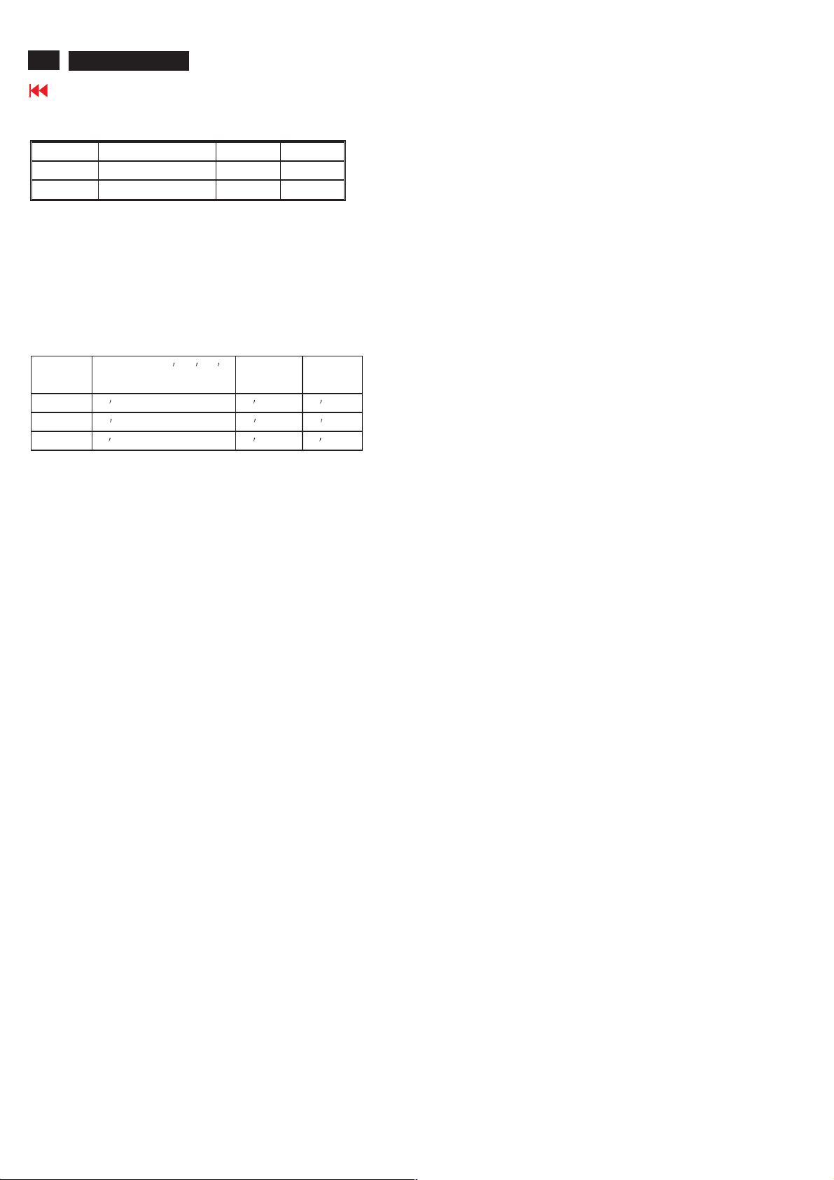
36
26MF605W/17
Color Adjustment
Go to cover page
1. Check (X, Y) co-ordinates as below :
Normal/ (8500°K)
x (center) 0.289 ± 0.015
y (center) 0.304 ± 0.015
Table 4: Reading with Minolta CA-110.
2. Check the gray level color poor & noise condition and chromaticity
Note:
1. Use Minolta CA-110 for color coordinates and luminance check.
2. Lumin ance> 400 cd/m
NORAML)color and PC Brightness control; Contrast control at 100%
2.2.3 Set Smart picture as "WARM", and "COOL" The SCALER
GAIN R\G\B value will be followed below
Normal/ the R \G \B
are gain after alignment.
R gain R R R -10
G gain G G -10 G -10
B gain B B -10 B
2
in the center of the screen at Original (
WARM COOL
.
2.3 Check the dig ital interf ace cable (B )
Check the 64 gray level color poor & noise condition.
Page 37
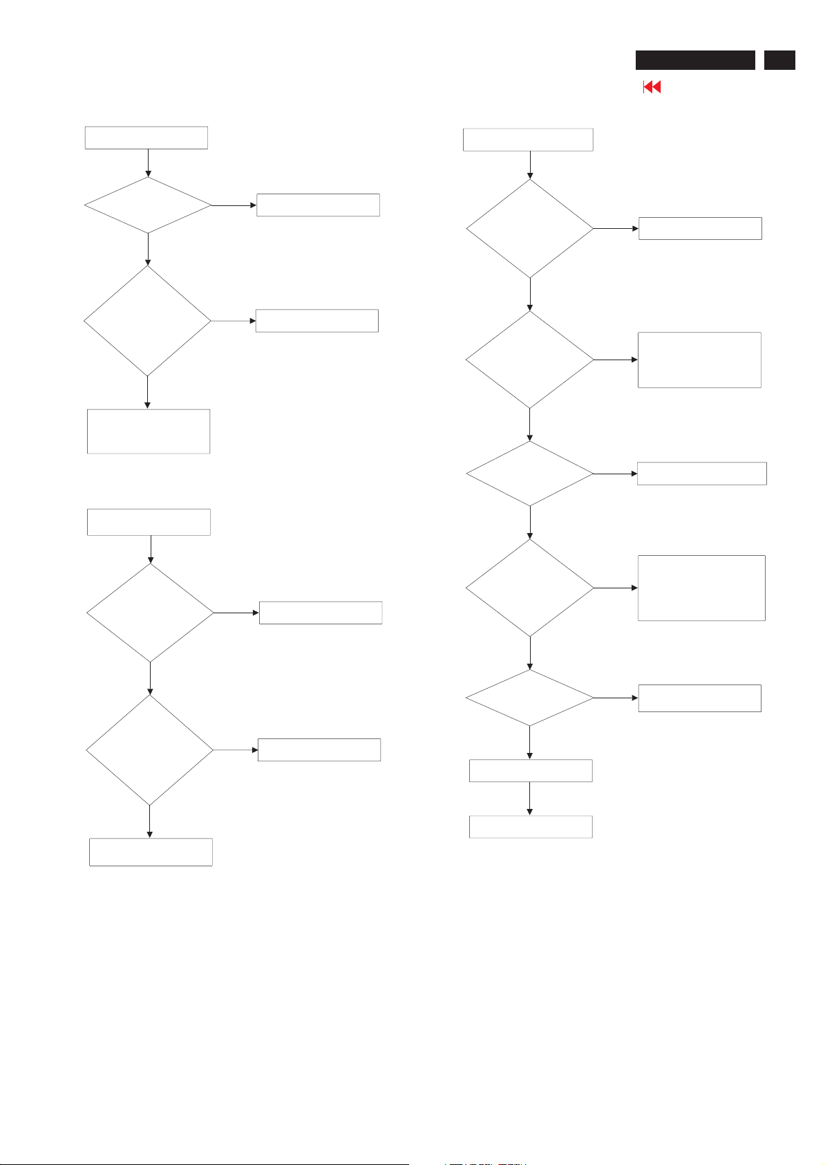
Repair Flow Chart
26MF605W/17
Go to cover page
37
1.No work/LED is off
Check if
power switch is
normal
Yes
Check
power board 1089
pin1,2=16V,pin3=24V,
pin4=1.8V,pin5=
4.6V
Yes
Check scaler board1503
pin1=1.18V,pin2~5=3.3V
2.No raster/picture too
dim
No
Replace Power switch
No
Check power board
3.No picture/LED is green
Check
power board 1088,
pin1~5=24V,pin6=
1.8V pin7=4.6V
Yes
Check if
working voltage
7501 pin3=3.3V,3524=
3.3V,3530=3.3V
Yes
Check if clock
source 1301,1502,
1731
Yes
No
Check power board
Check circuit around
No
each regulator and
eliminate short and
open situation
No
Replace 1301,1502,1731
Check
power board 1088,
pin1~5=24V,pin6=
1.8V pin7=4.6V
Yes
Check
power board 1089
pin1,2=16V,pin3=24V,
pin4=1.8V,pin5=
4.6V
Yes
Check scaler board
No
Check power board
No
Check power board
Check if
scaler 7403 RGB,
clk,H/V and DE signal
output 128 bits
TTL
Yes
Check
resistors-network
Yes
Replace LVDS cable
Yes
Replace LCD panel
Try to replace
CPU or CPU's flash Rom
No
CPU's EEPROM
Painter
Painter's EEPROM
No
Replace bad resistorsnetwork
Page 38
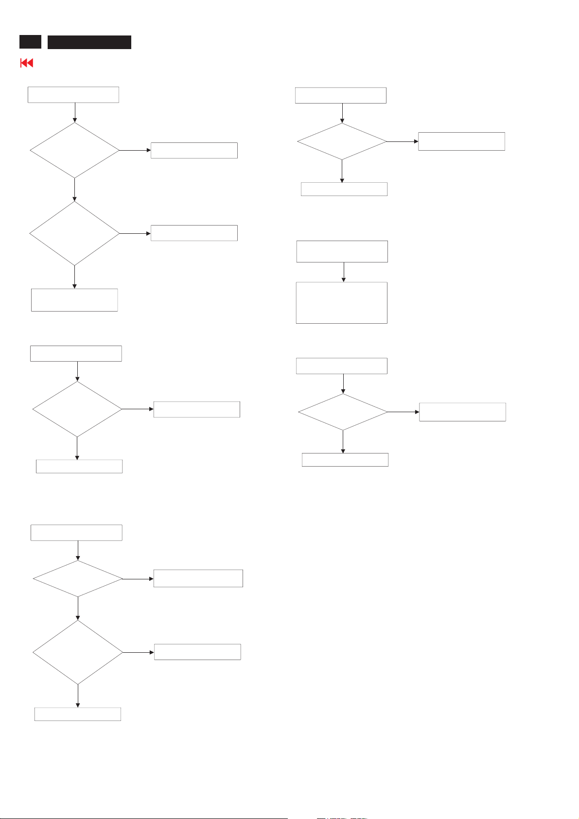
38
26MF605W/17
Go to cover page
Repair Flow Chat
4.No D-Sub picture
Check if
H/V signals input
to schmitt trigger
7122
Yes
Check if
schmitt trigger 7122
output H/V signals to
JAGASM
Yes
Go to 3.No picture/LED
is green
5.No TV sound
No
Check input path
No
Replace 7122
7.No remote function
Tty another
remote control
Yes
Check IR receiver
8.LED and function
key poor
Check circuit around
control board and cable
between control board
and scaler board
9.No HDCP picture
Replace one good
No
remote control
Check if
tuner 1811 pin11
output 2nd IF
signal
Yes
Check 7821
6.No earthphone sound
Check
7814 5162=16V
Yes
Check 7814
pin2=MSP-OUT-R
pin6=MSP-OUT-L
No
Replace 1811
Eliminate short and open
No
situation
No
Replace 7814
Check 7101
has HDCP code
Yes
Check Scaler Board
Write HDCP code in
No
7101
Yes
Replace Side AV Board
Page 39
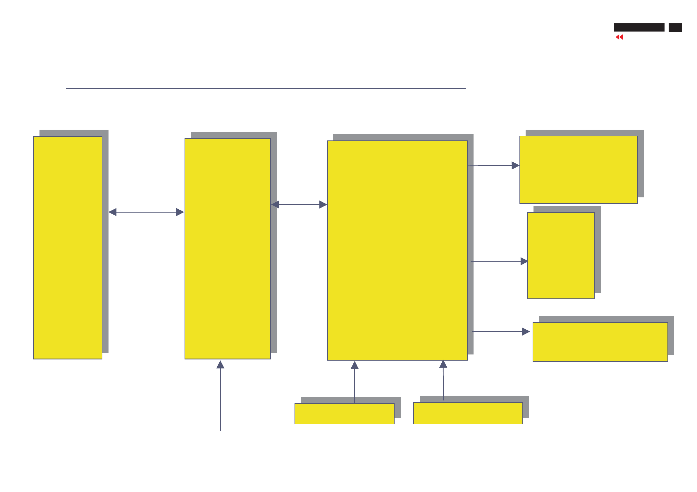
1. Function block & PCB Dimension:
Basic structure:
Block Diagram-1
LVDS Panel
26”/27”/32”
26MF605W/17
Go to cover page
39
Inverter
board
Vcc,
Bright_ADJ
Inverter ON_OFF
PWR_SAVING
SMPS
board
SCALER BOARD
SAA7119 +
MSP34X0 +
Columbus +
MST51512 +
TPA3004D2 or
TPA3005D2
Speaker
2x5W or
2X10W
HD Board
HD Board
( for NAFTA/AP/China )
( for NAFTA/AP/China )
Mains
Side AV Board
Side AV Board
Control Board
Page 40
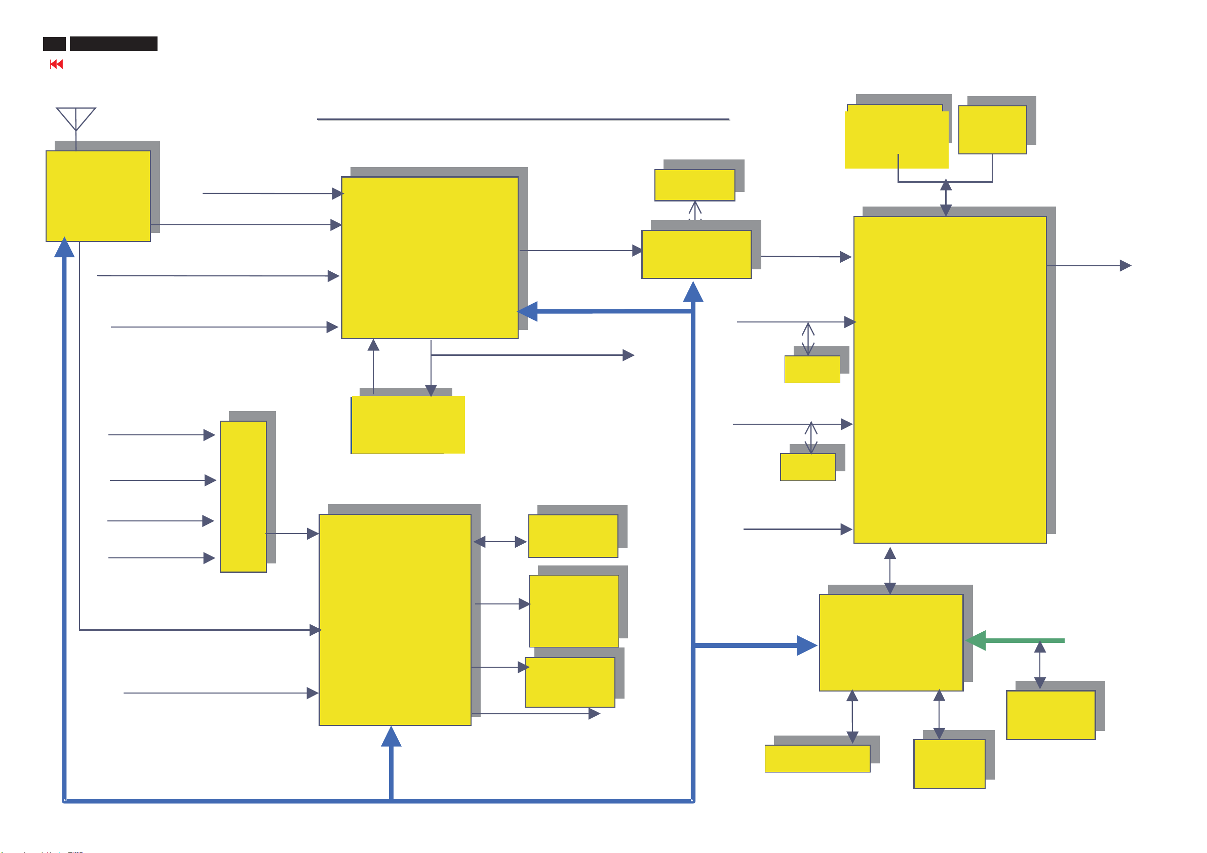
40
26MF605W/17
Go to cover page
Block Diagram-2
MM
YPbPr/RGB IN
Tuner
TUN_CVBS
SC1(AV1) / SC2 (AV2 )/ AV3 CVBS_IN
SC2(S-Video1)/ S-Video2 S-Video IN
Function block of
Function block of
SAA7119
PVR CVBS_Out
R/G/B/FB
CVBS
_MON_out
Scaler
Scaler
Board
Board
SDRAM
SDRAM
Columbus
1Mx16
DVI HDCP
DDC
DDC
1Mx16
(USA only)
MST51512
1Mx16
LVDS
SC1/AV1_ Audio_IN
SC2/AV2_Audio_IN
PC_Audio_IN
DVI_Audio_IN
2ndIF
AV3_Audio /HD Audio
MUX
MUX
TT
SAA5630
MSP34XX
Audio
Audio
Delay
Delay
TPA3004/
TPA3004/
TPA3005
TPA3005
Audio Amp
Audio Amp
TDA1308
TDA1308
HP Amp
HP Amp
PC VGA D-Sub
DDC
DDC
HD_YPbPr Cinch
IIC
DDC_I2C (ISP)
MCU
VGA DDC
24C02
PVR Audio L/R
Keys/IR
Keys/IR
EEPROM
Page 41
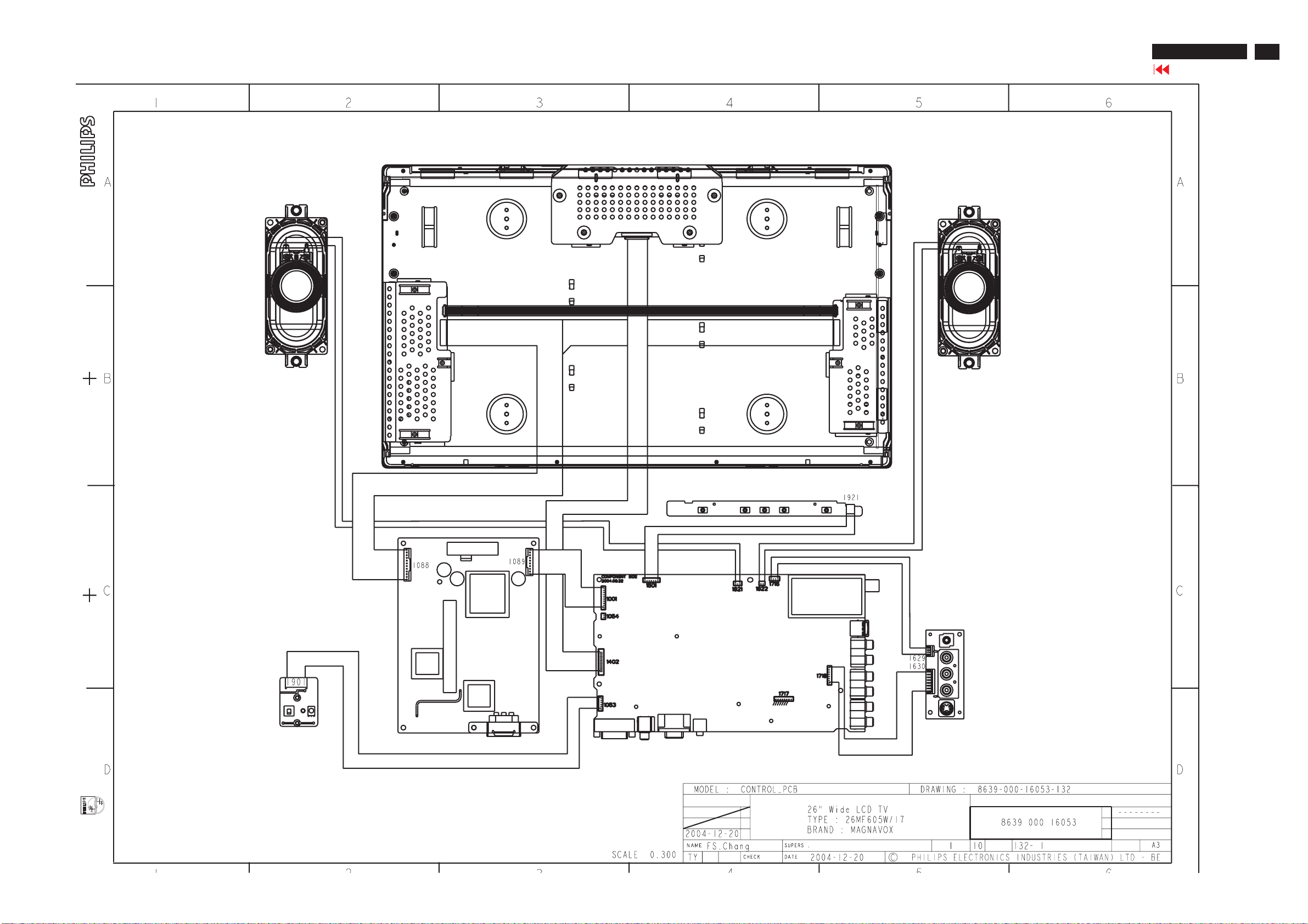
Wiring Diagram
26MF605W/17
Go to cover page
41
Page 42
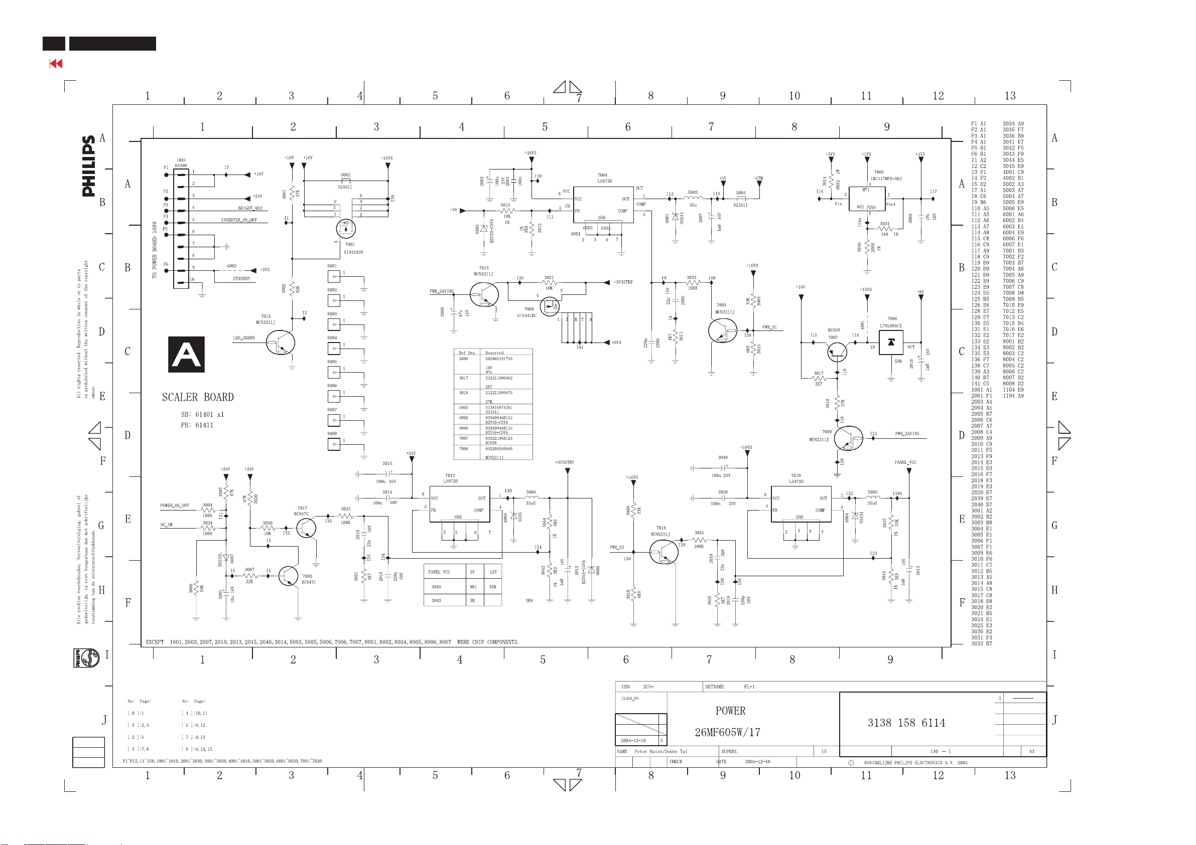
42
26MF605W/17
Go to cover page
Scaler Diagram-1
Page 43
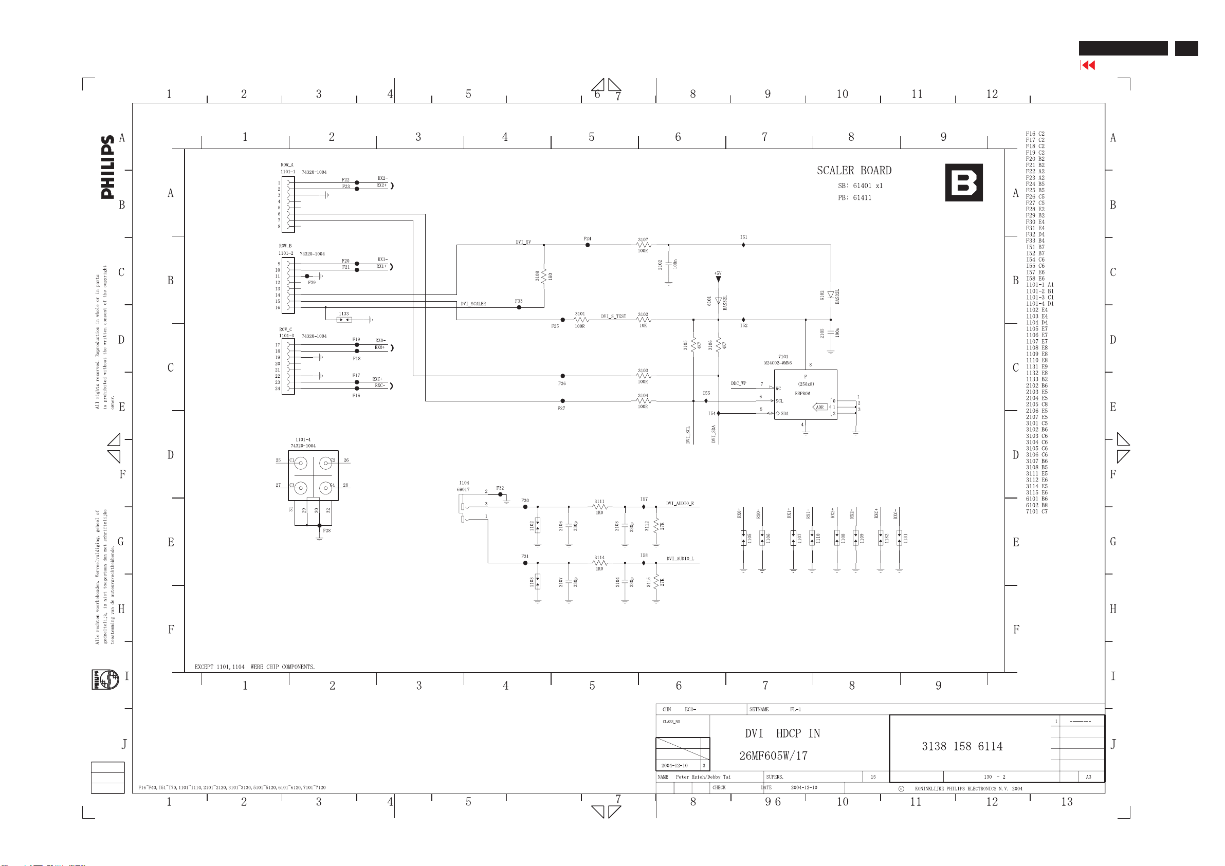
Scaler Diagram-2
26MF605W/17
Go to cover page
43
Page 44
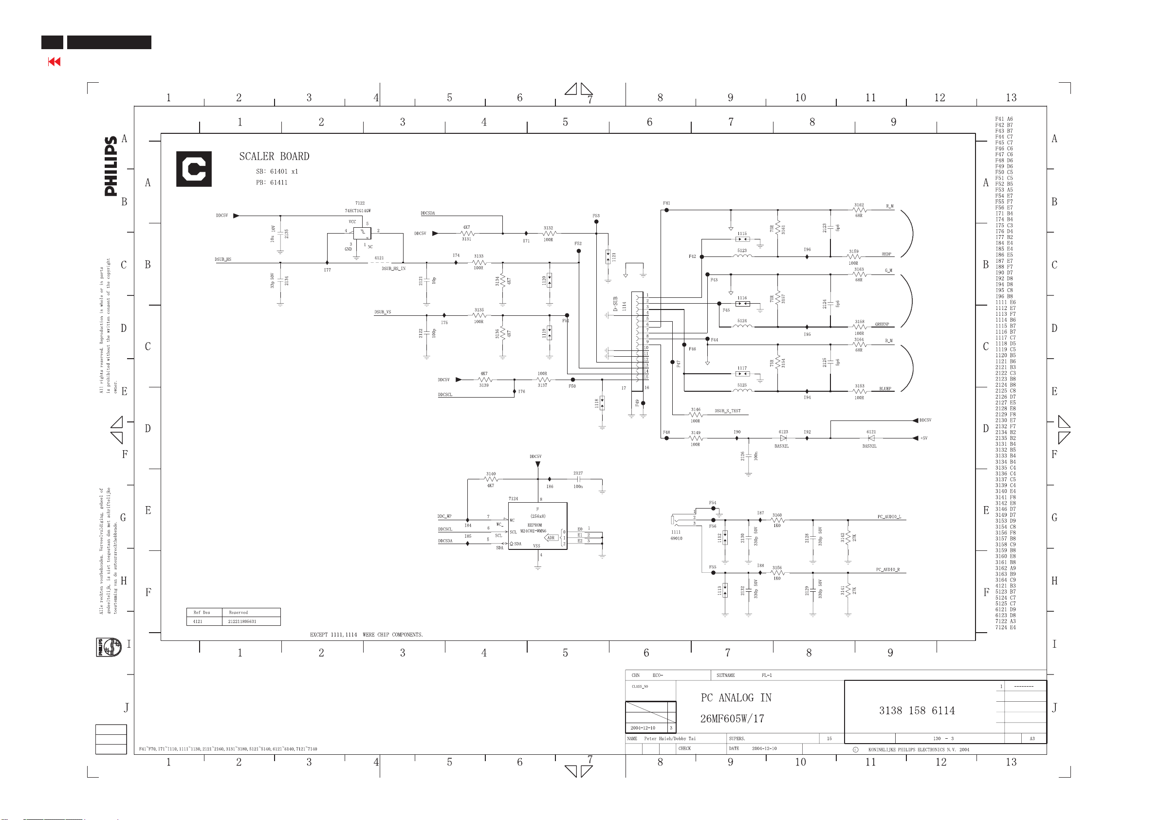
44
26MF605W/17
Go to cover page
Scaler Diagram-3
Page 45
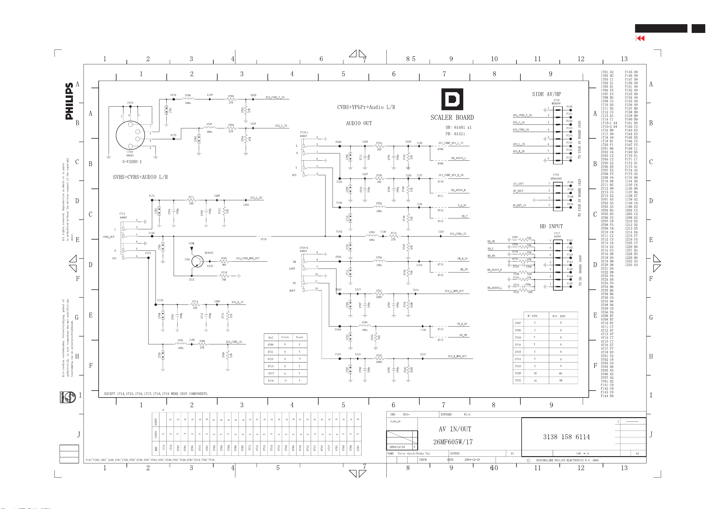
Scaler Diagram-4
26MF605W/17
Go to cover page
45
Page 46
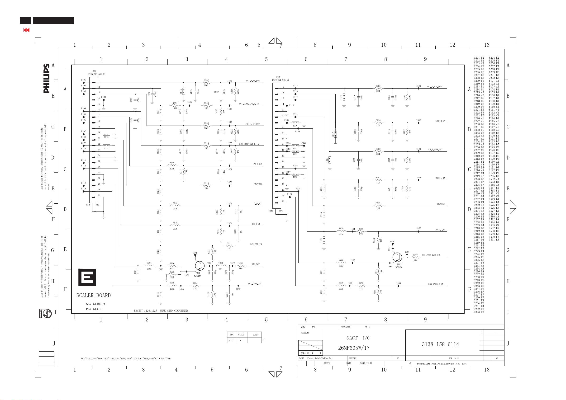
46
26MF605W/17
Go to cover page
Scaler Diagram-5
Page 47
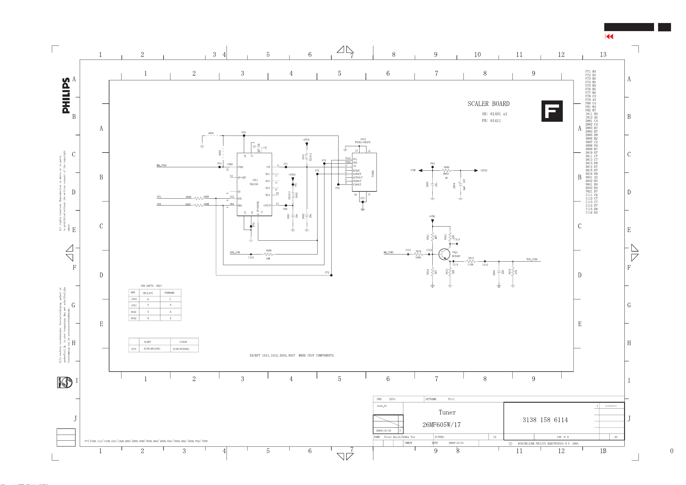
Scaler Diagram-6
26MF605W/17
Go to cover page
47
Page 48
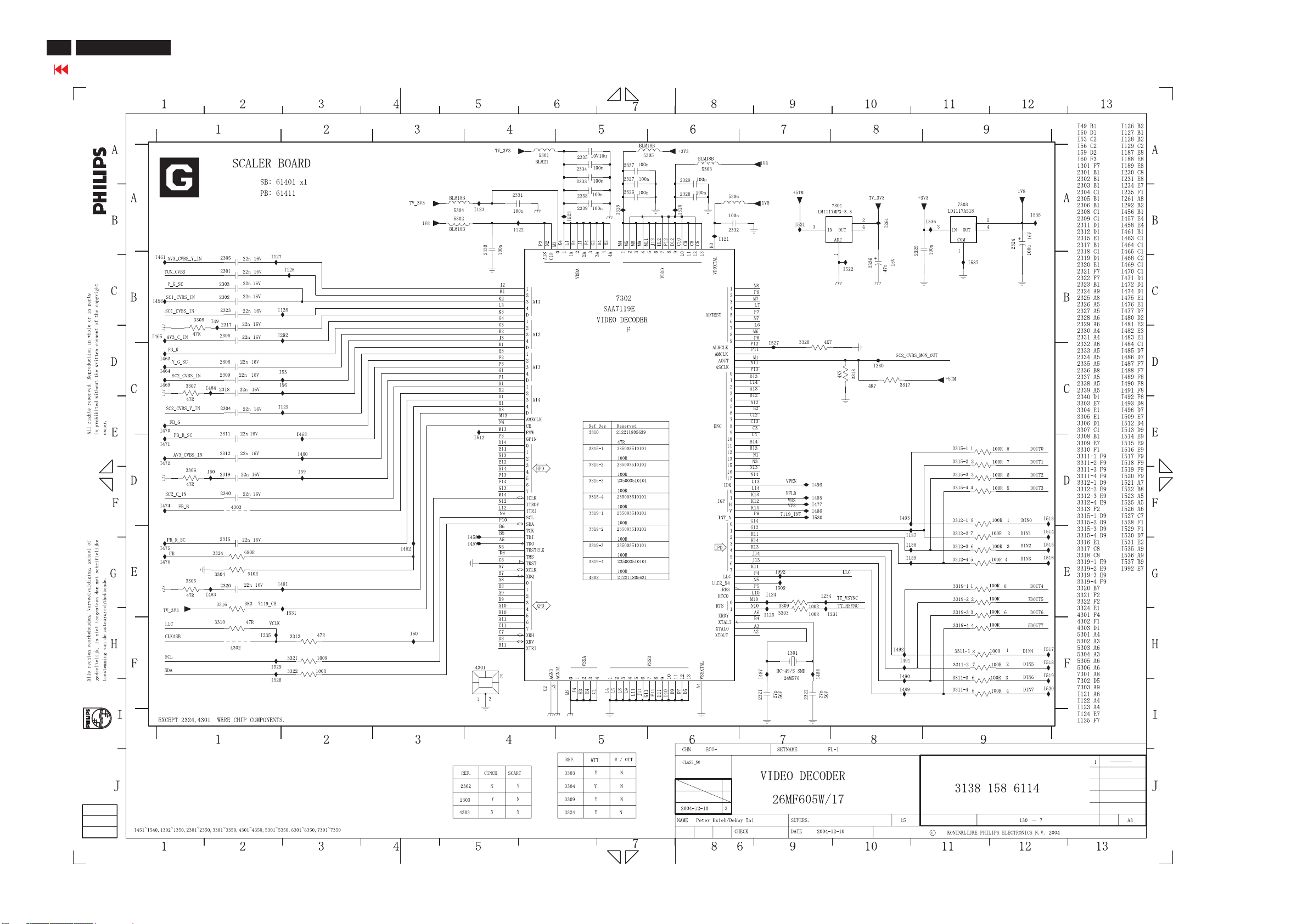
48
26MF605W/17
Go to cover page
Scaler Diagram-7
Page 49
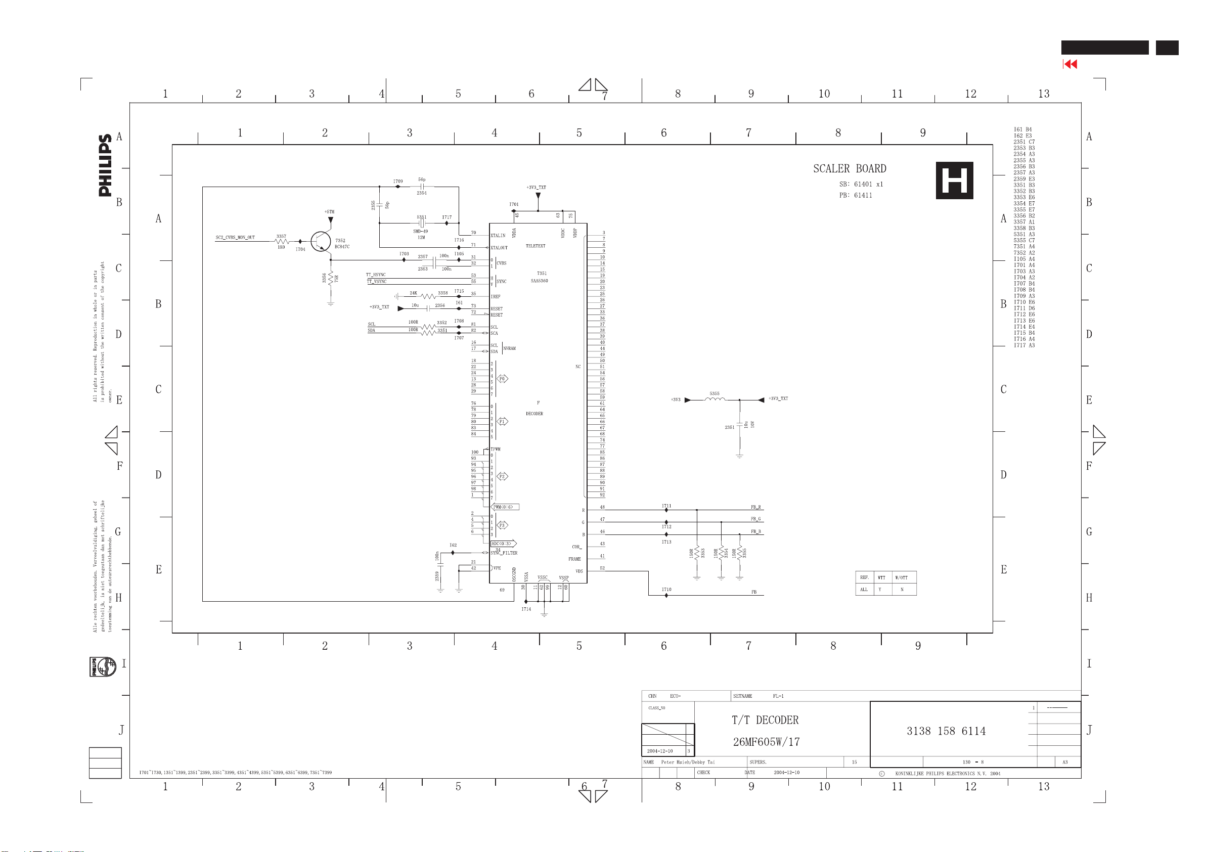
Scaler Diagram-8
26MF605W/17
Go to cover page
49
Page 50
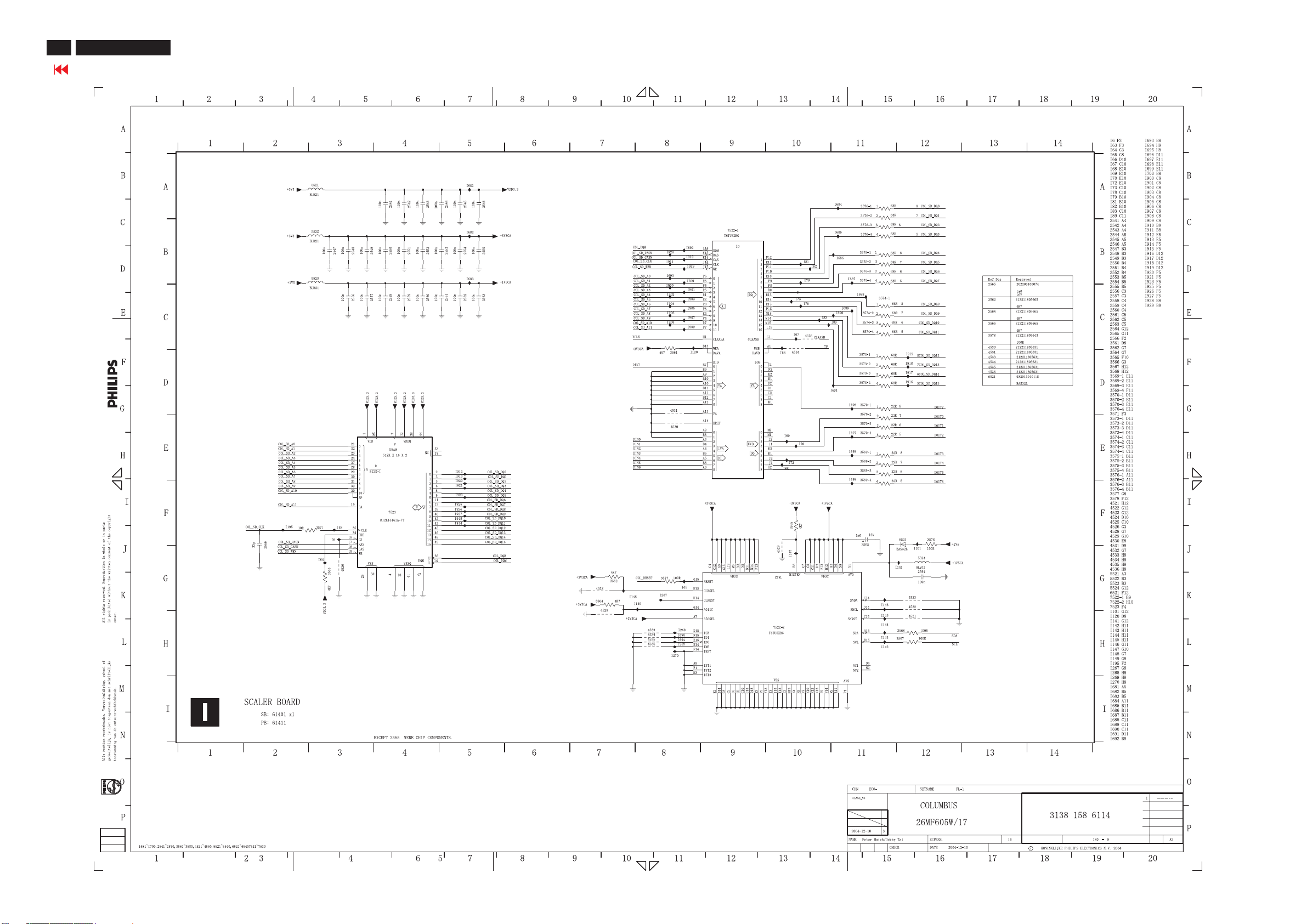
50
26MF605W/17
Go to cover page
Scaler Diagram-9
Page 51
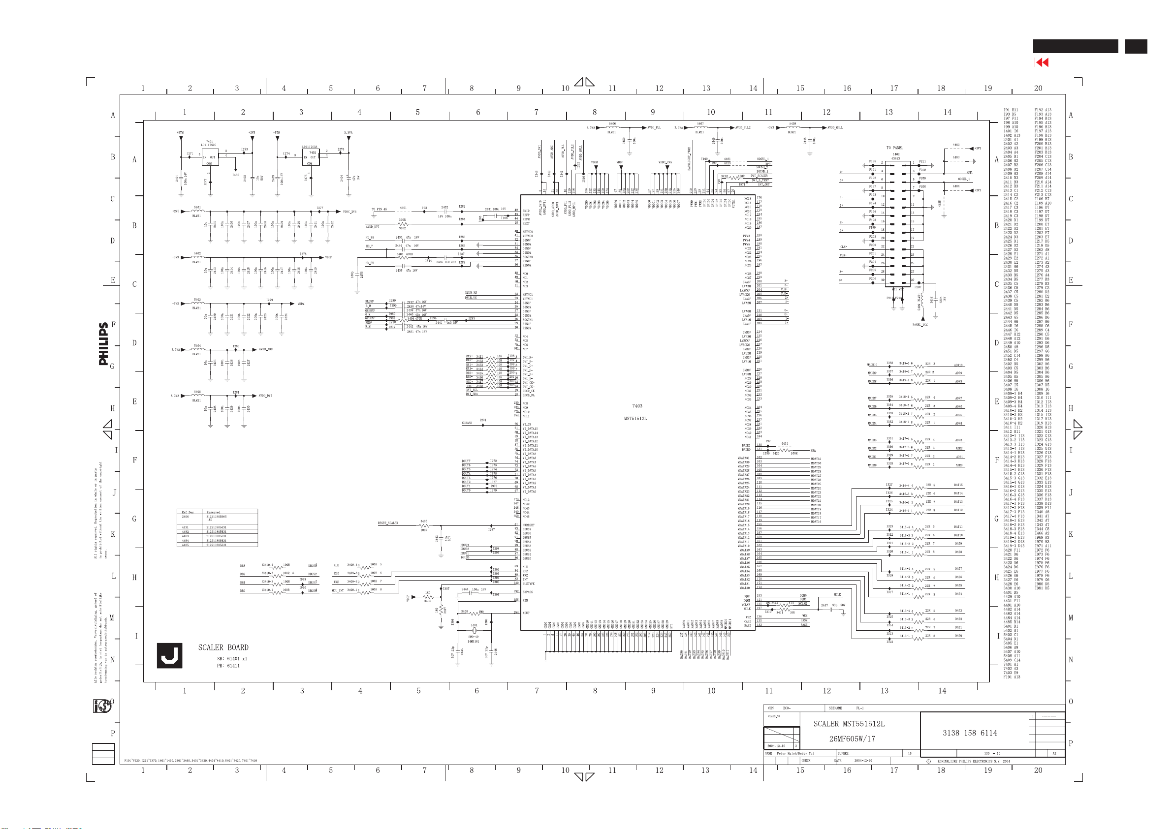
Scaler Diagram-10
26MF605W/17
Go to cover page
51
Page 52
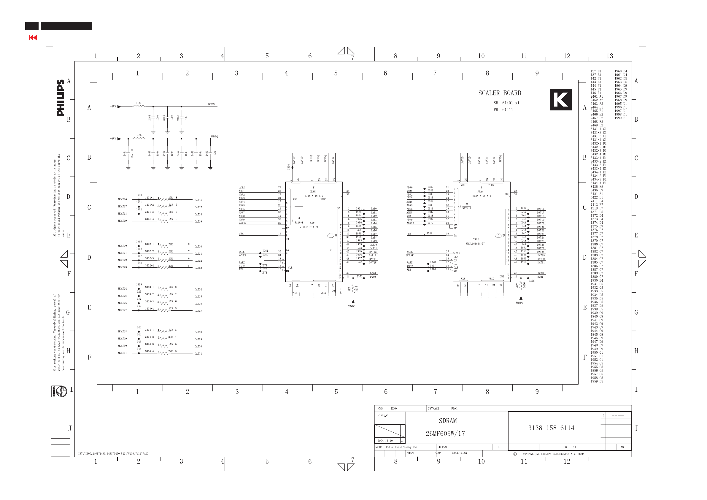
52
26MF605W/17
Go to cover page
Scaler Diagram-11
Page 53
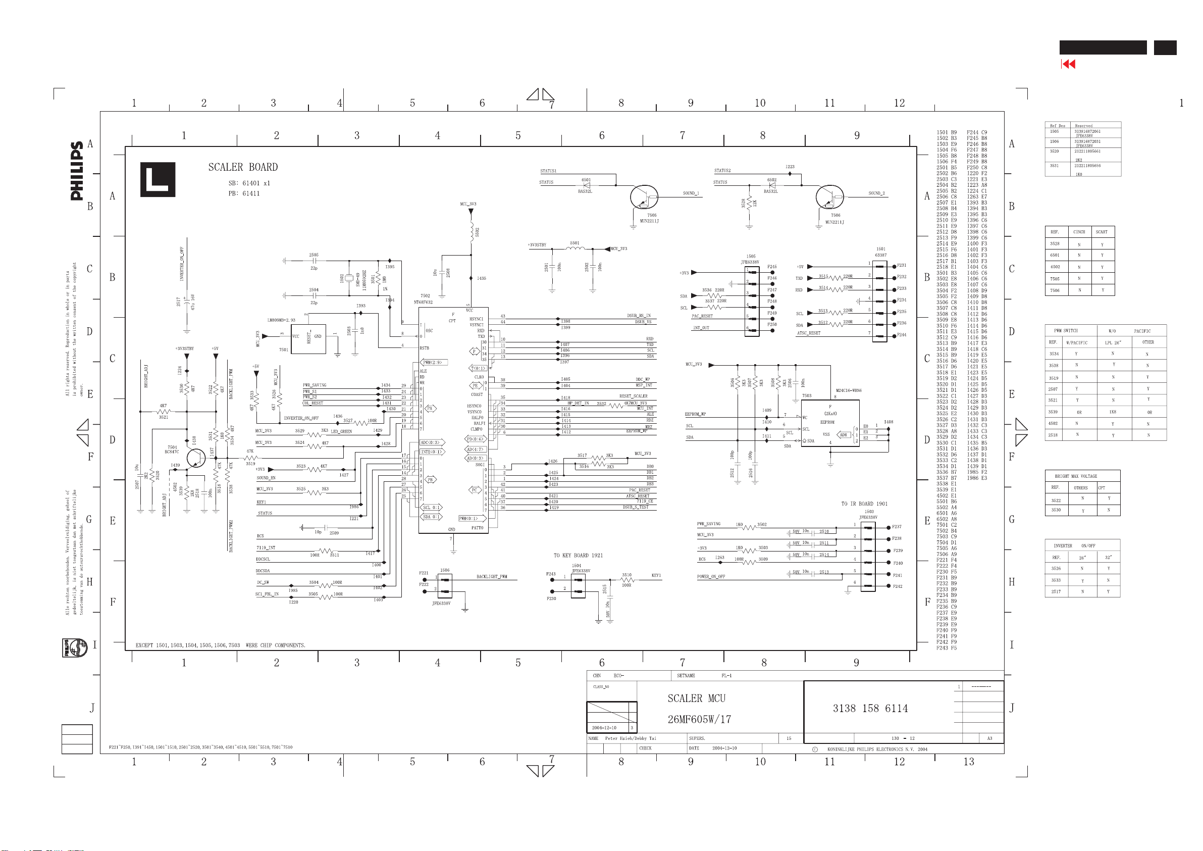
Scaler Diagram-12
26MF605W/17
Go to cover page
53
Page 54
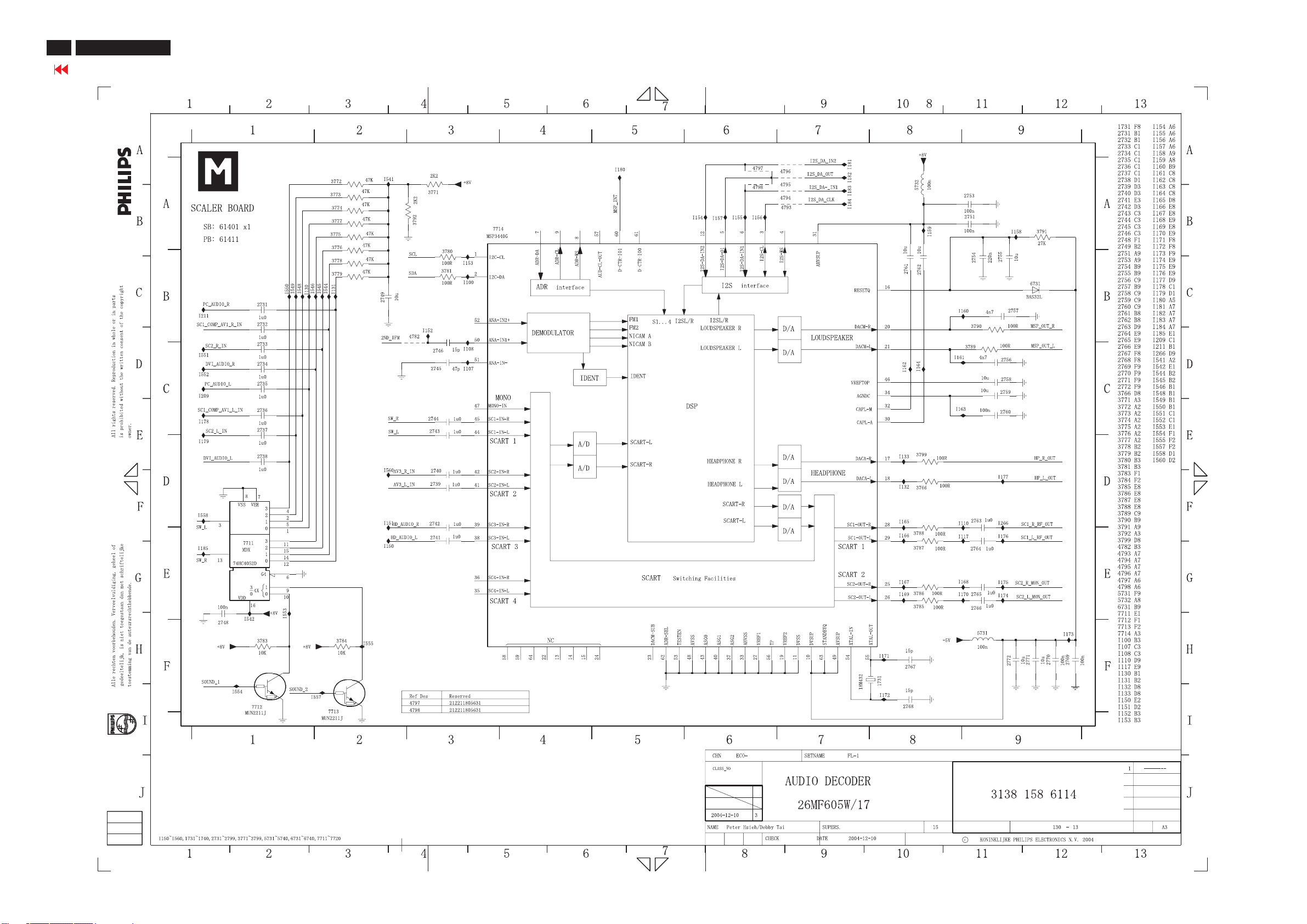
54
26MF605W/17
Go to cover page
Scaler Diagram-13
Page 55
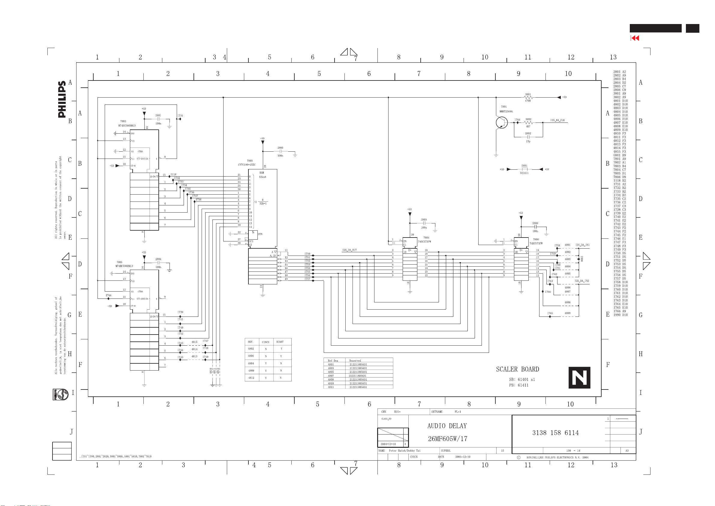
Scaler Diagram-14
26MF605W/17
Go to cover page
55
Page 56
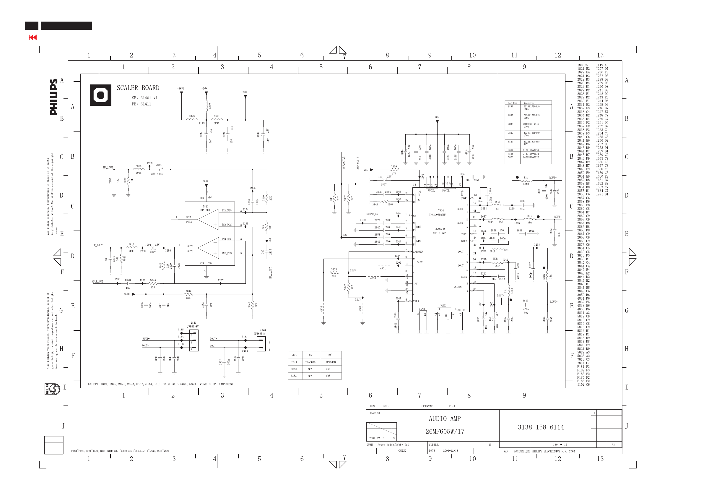
56
26MF605W/17
Go to cover page
Scaler Diagram-15
Page 57
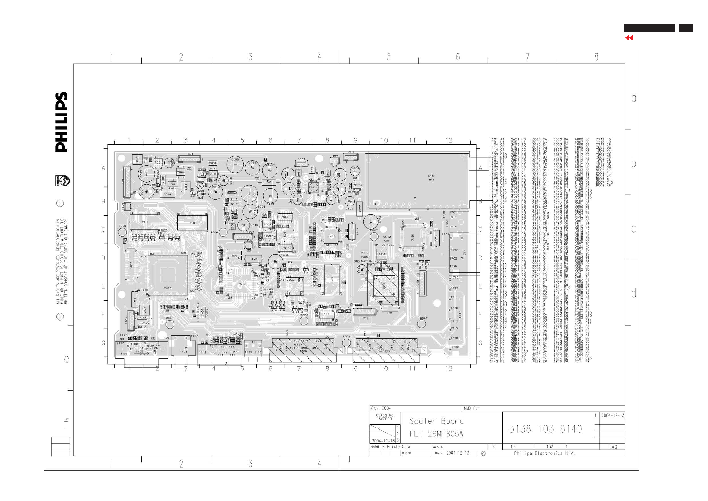
Scaler Board C.B.A.-1
26MF605W/17
Go to cover page
57
Page 58
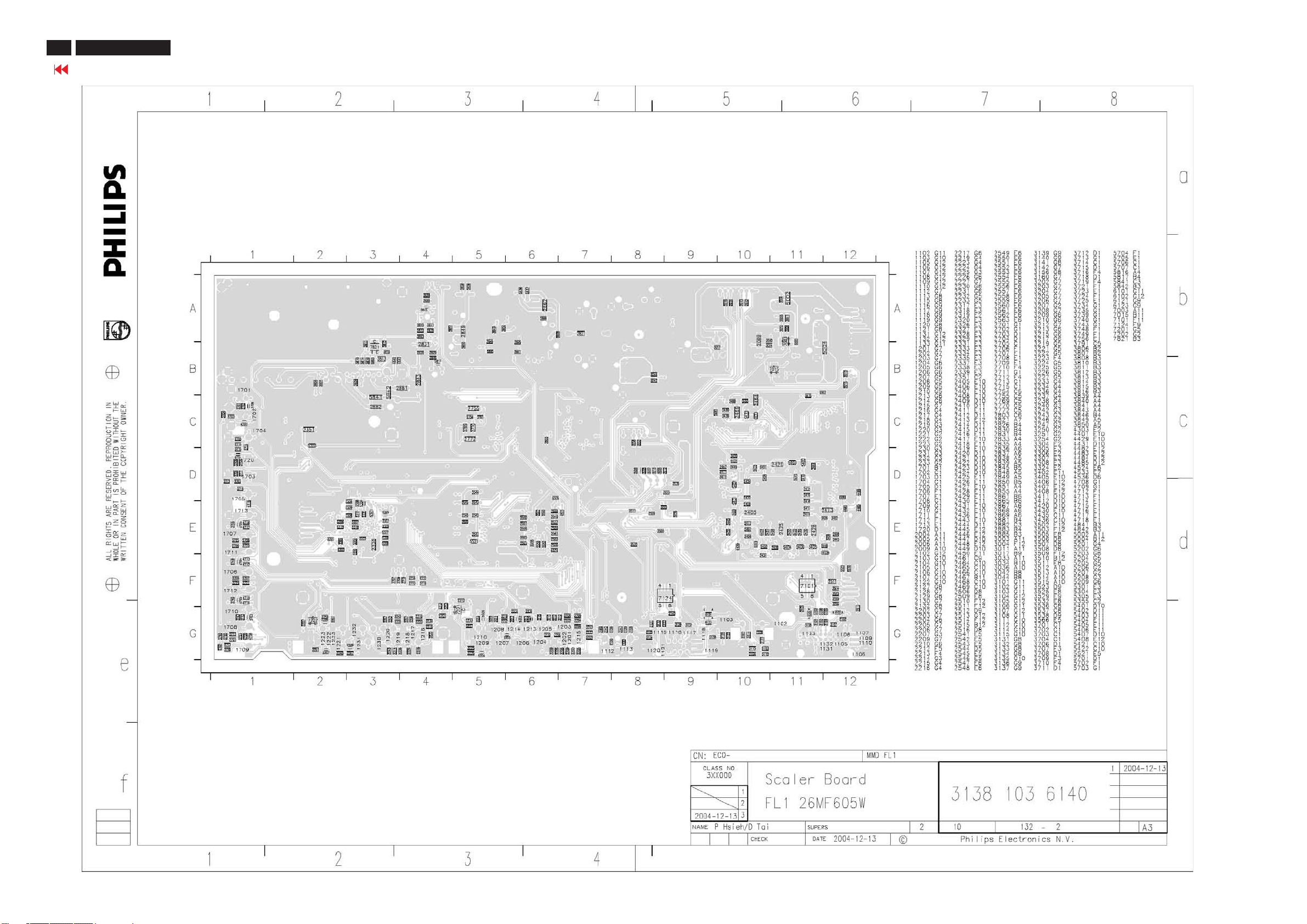
58
26MF605W/17
Go to cover page
Scaler Board C.B.A.-2
Page 59
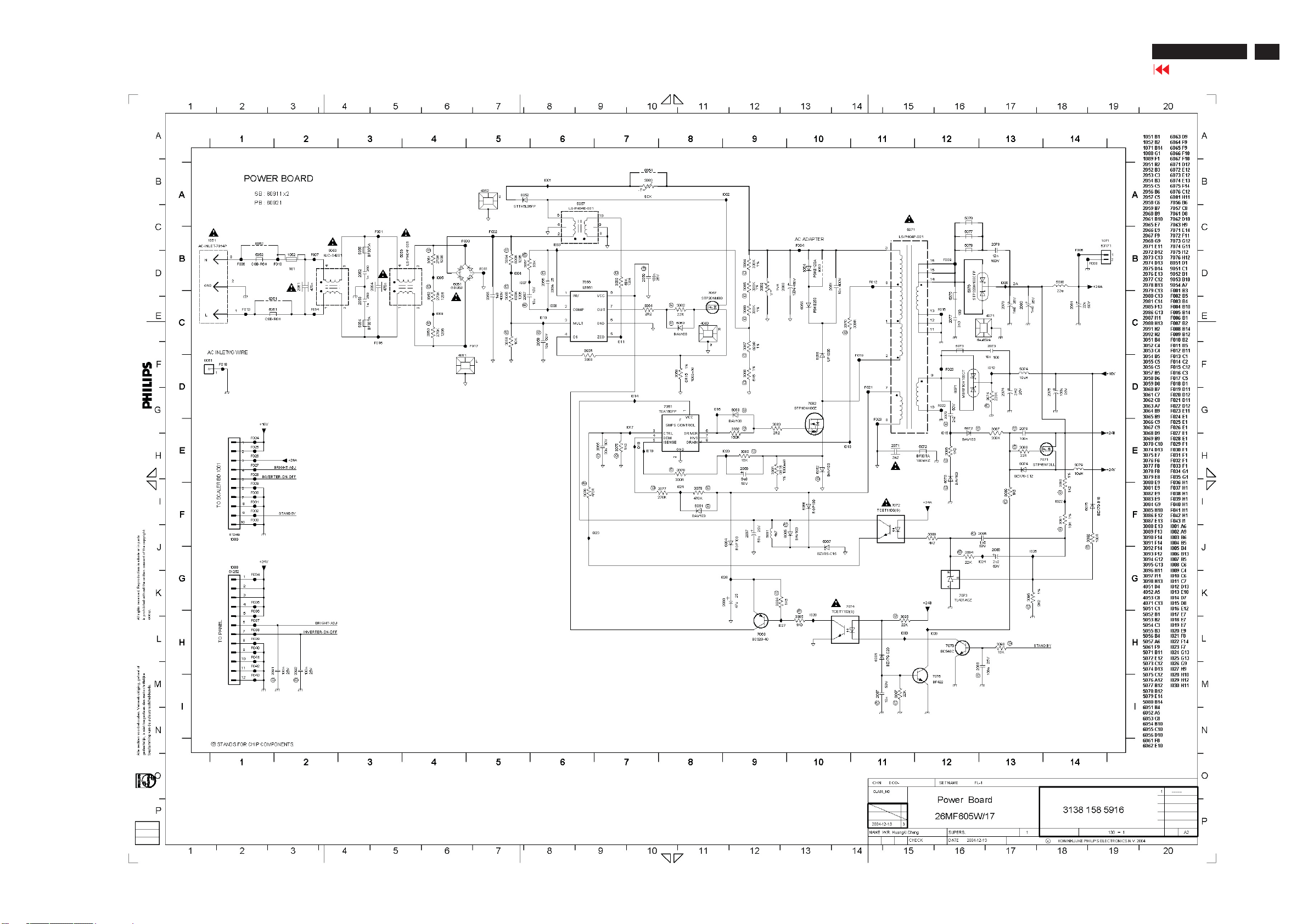
Power Diagram(26MF605W/17)
26MF605W/17
Go to cover page
59
Page 60
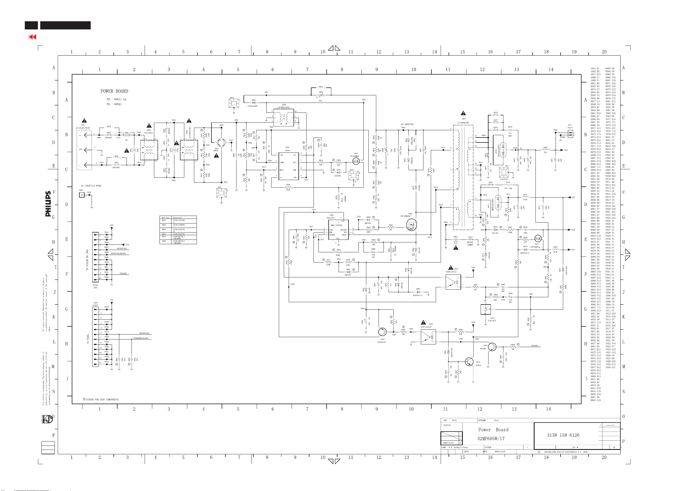
60
26MF605W/17
Go to cover page
Power Diagram(32MF605W/17)
Page 61
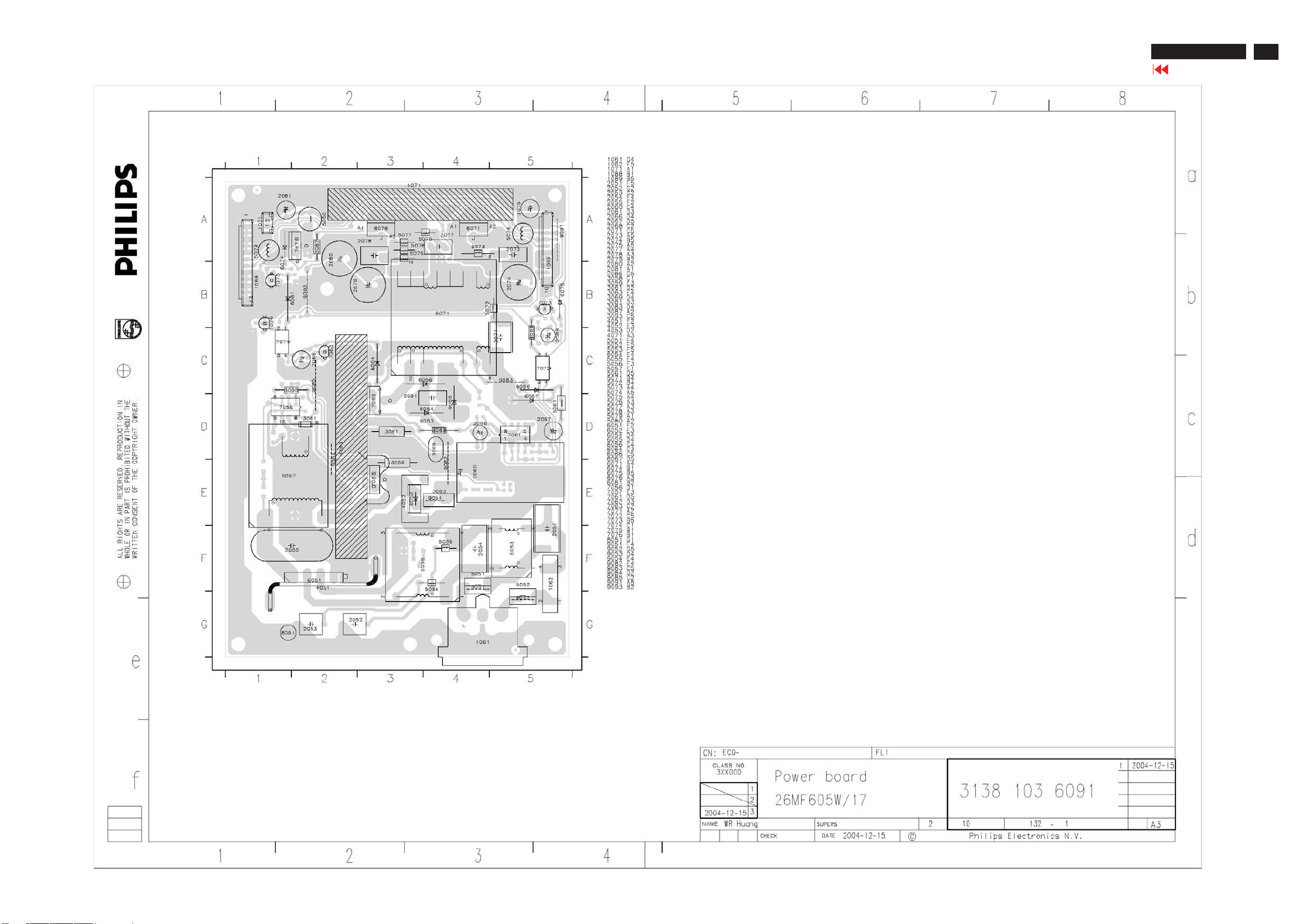
Power Board C.B.A-1
26MF605W/17
Go to cover page
61
Page 62
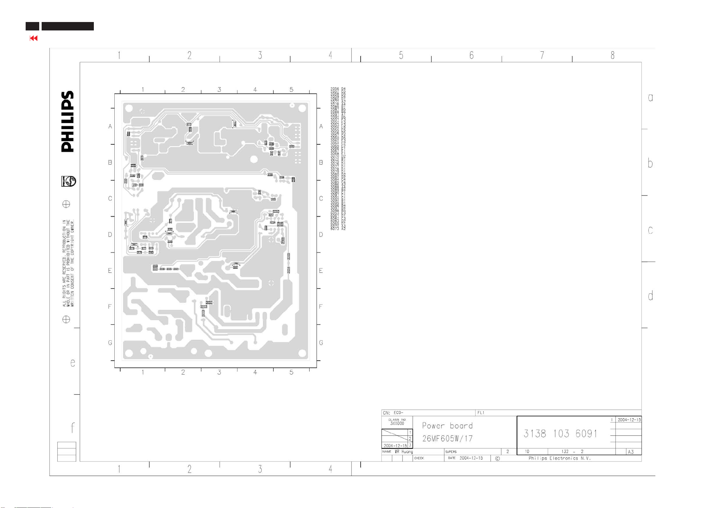
62
26MF605W/17
Go to cover page
Power Board C.B.A-2
Page 63
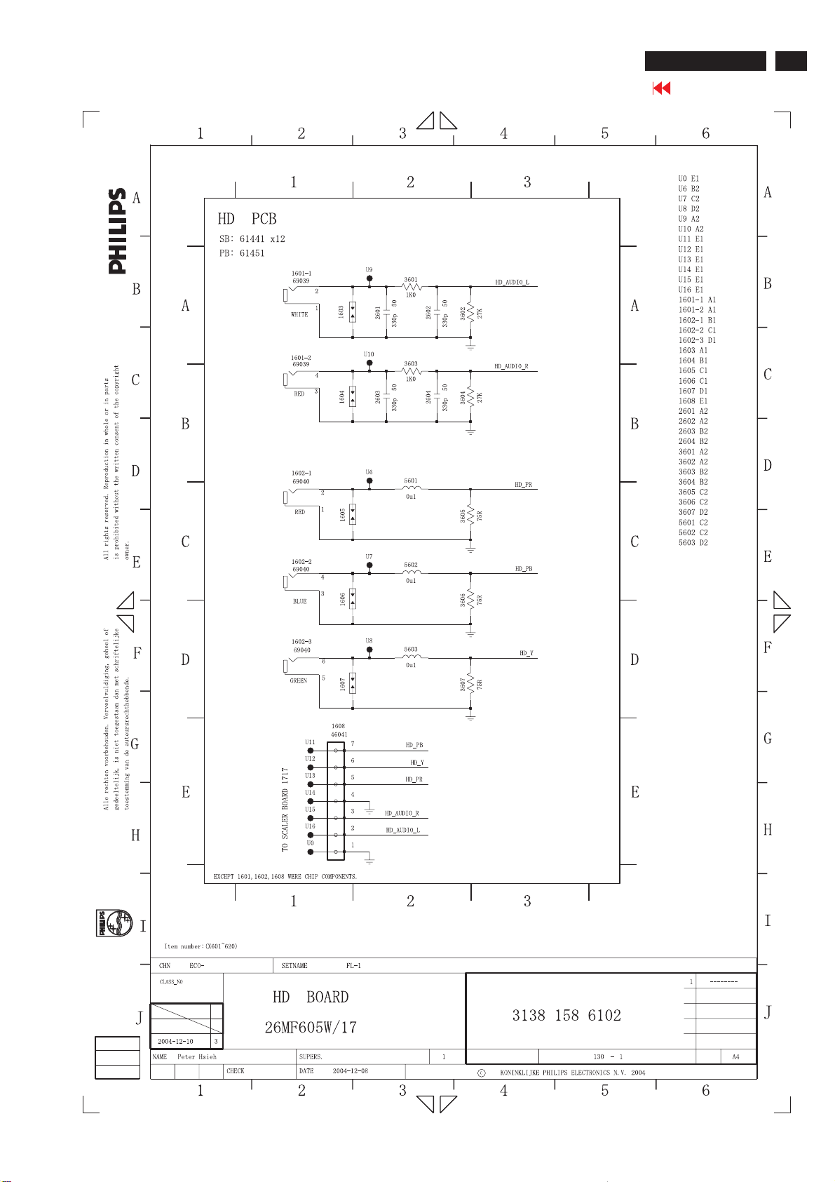
HD Diagram
26MF605W/17
Go to cover page
63
Page 64
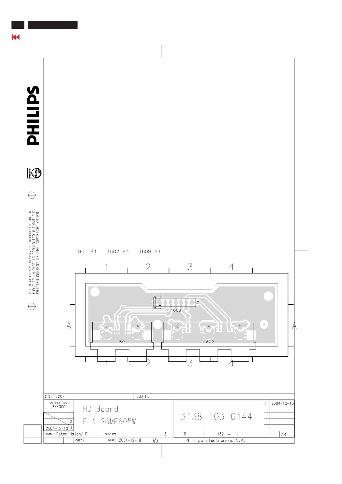
64
26MF605W/17
Go to cover page
HD Board C.B.A-1
Page 65
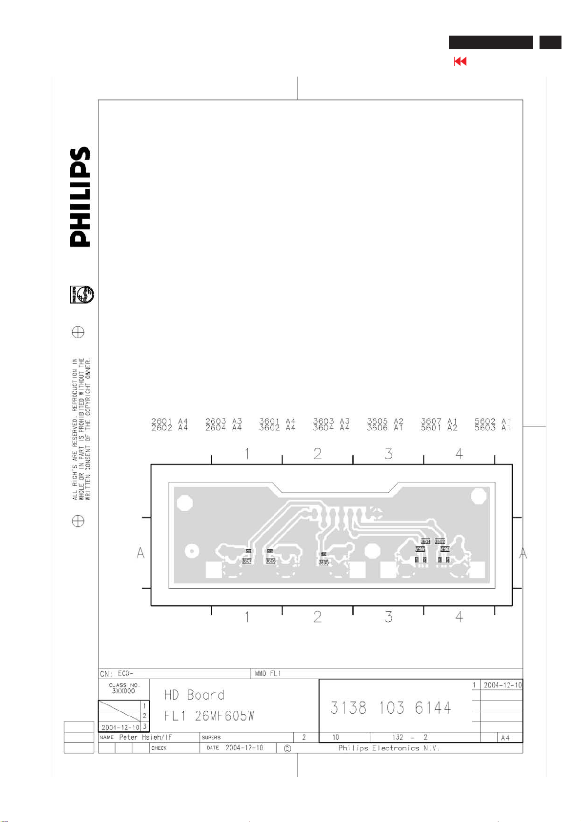
HD Board C.B.A-2
26MF605W/17
Go to cover page
65
Page 66
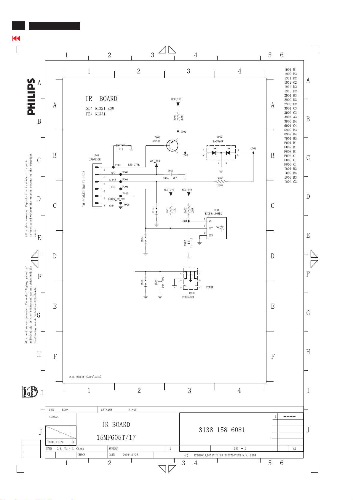
66
26MF605W/17
Go to cover page
IR Diagram
Page 67
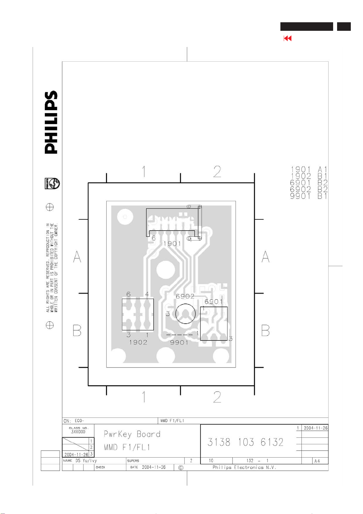
IR Board C.B.A-1
26MF605W/17
Go to cover page
67
Page 68
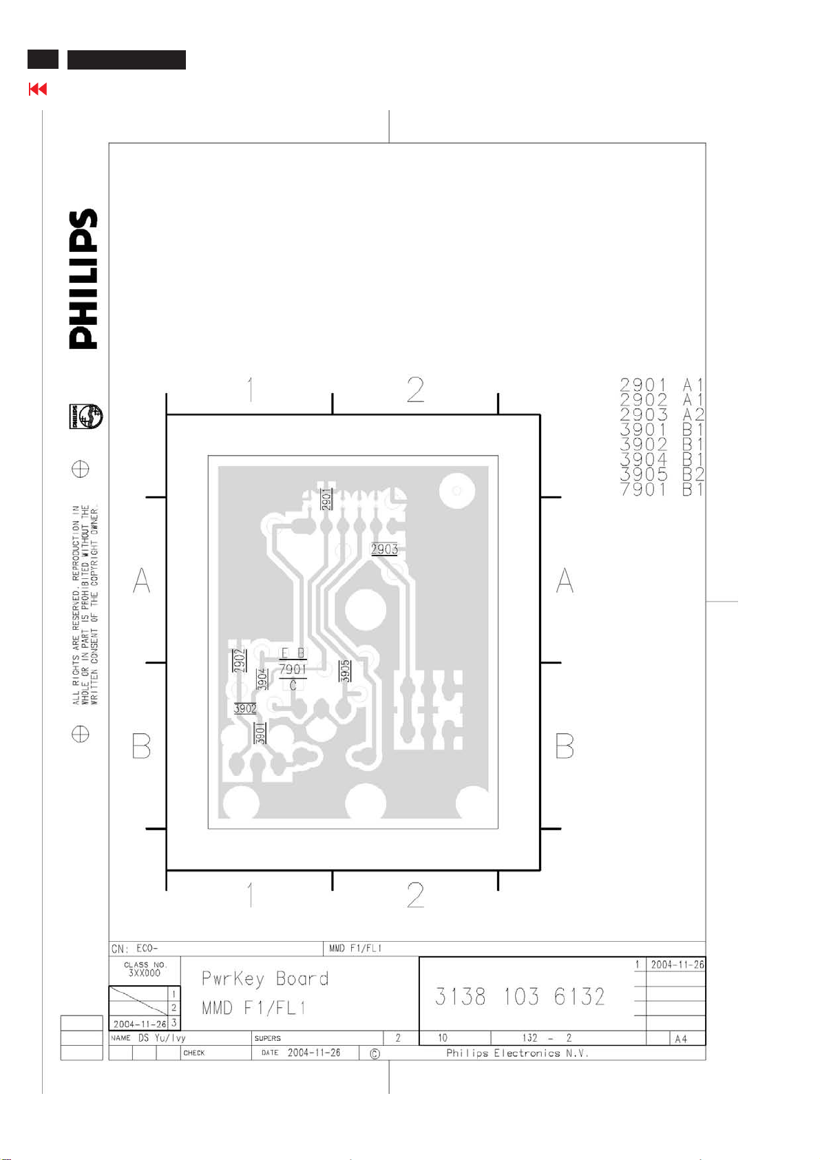
68
26MF605W/17
Go to cover page
IR Board C.B.A-2
Page 69
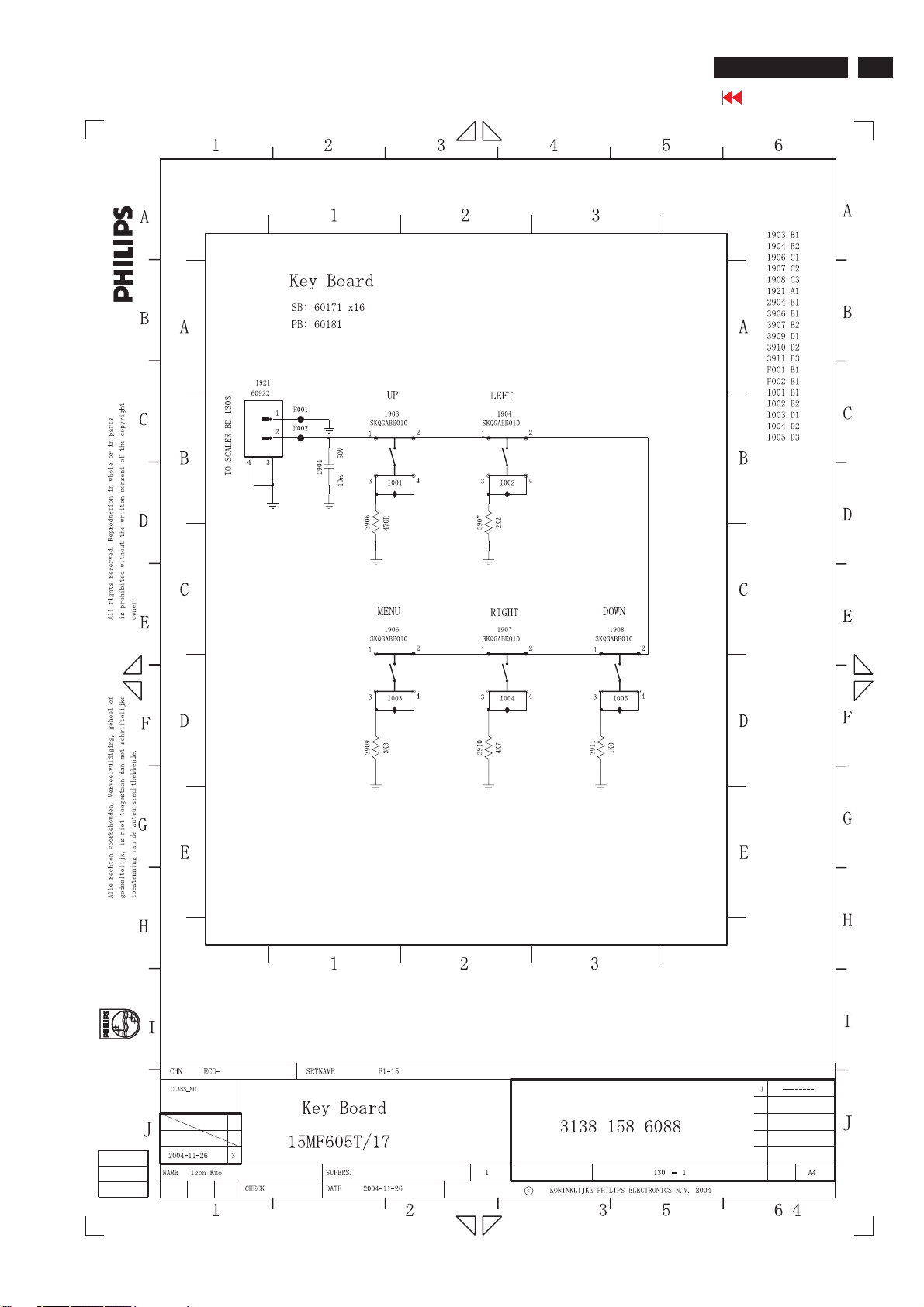
KEY Diagram
26MF605W/17
Go to cover page
69
Page 70
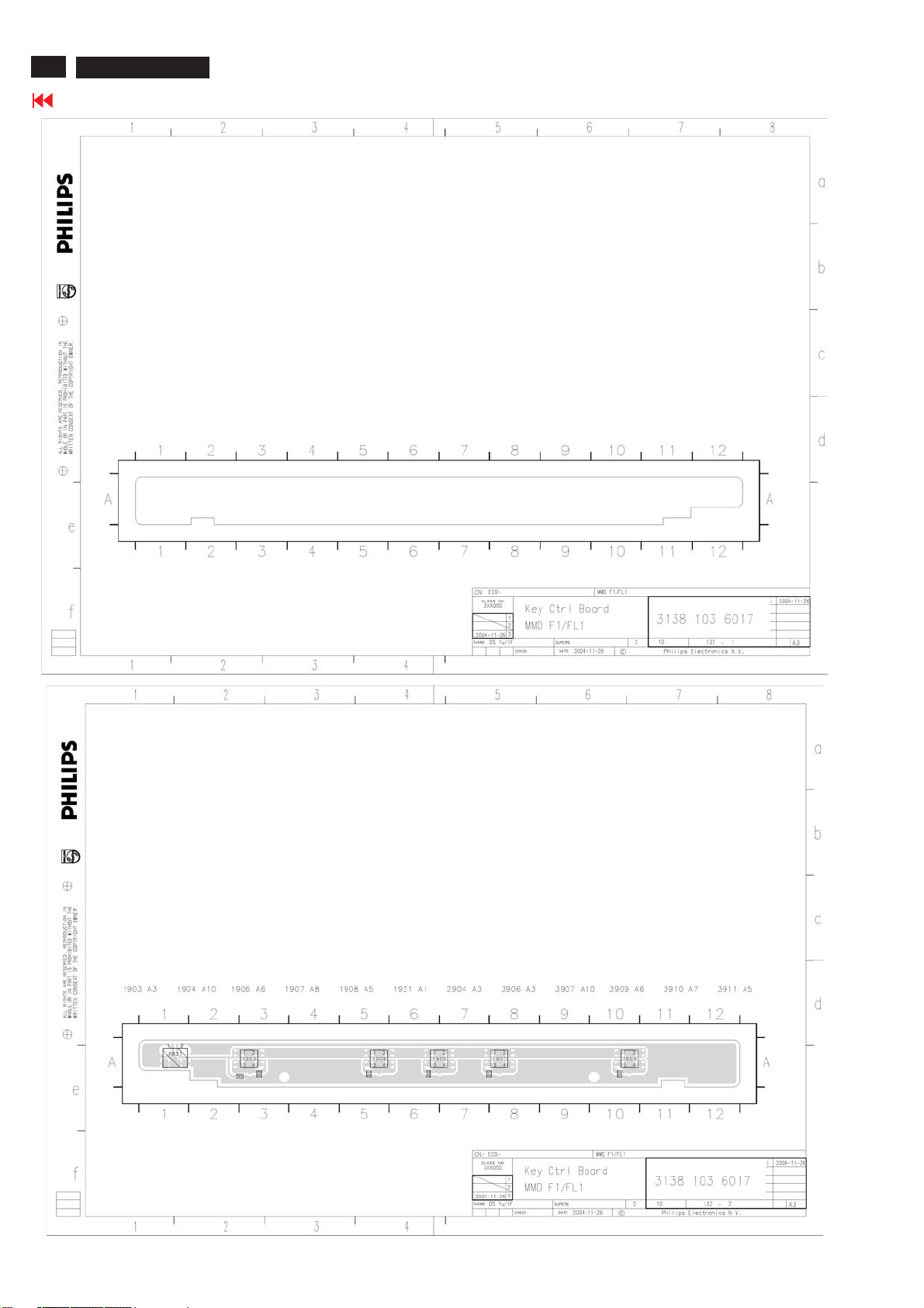
70
26MF605W/17
Go to cover page
KEY Board C.B.A
Page 71
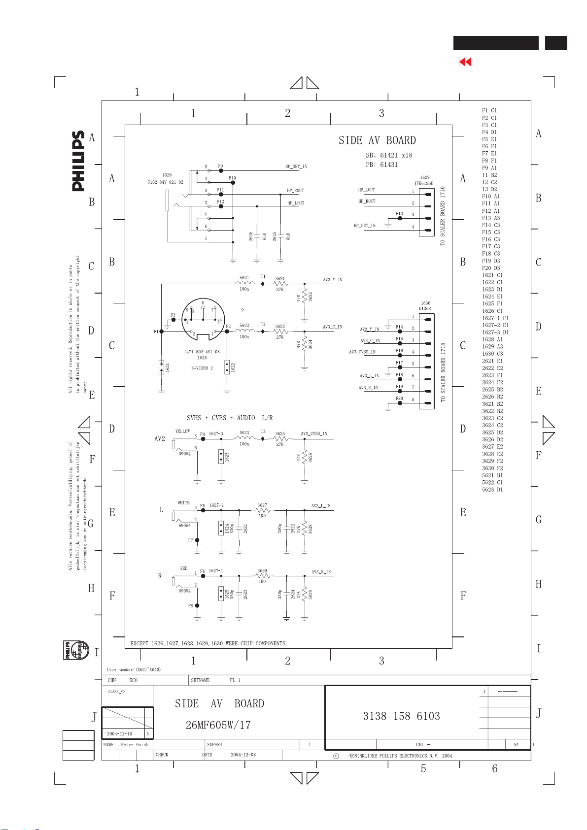
SIDE AV Diagram
26MF605W/17
Go to cover page
71
2
3
45
6
2
3
4
Page 72
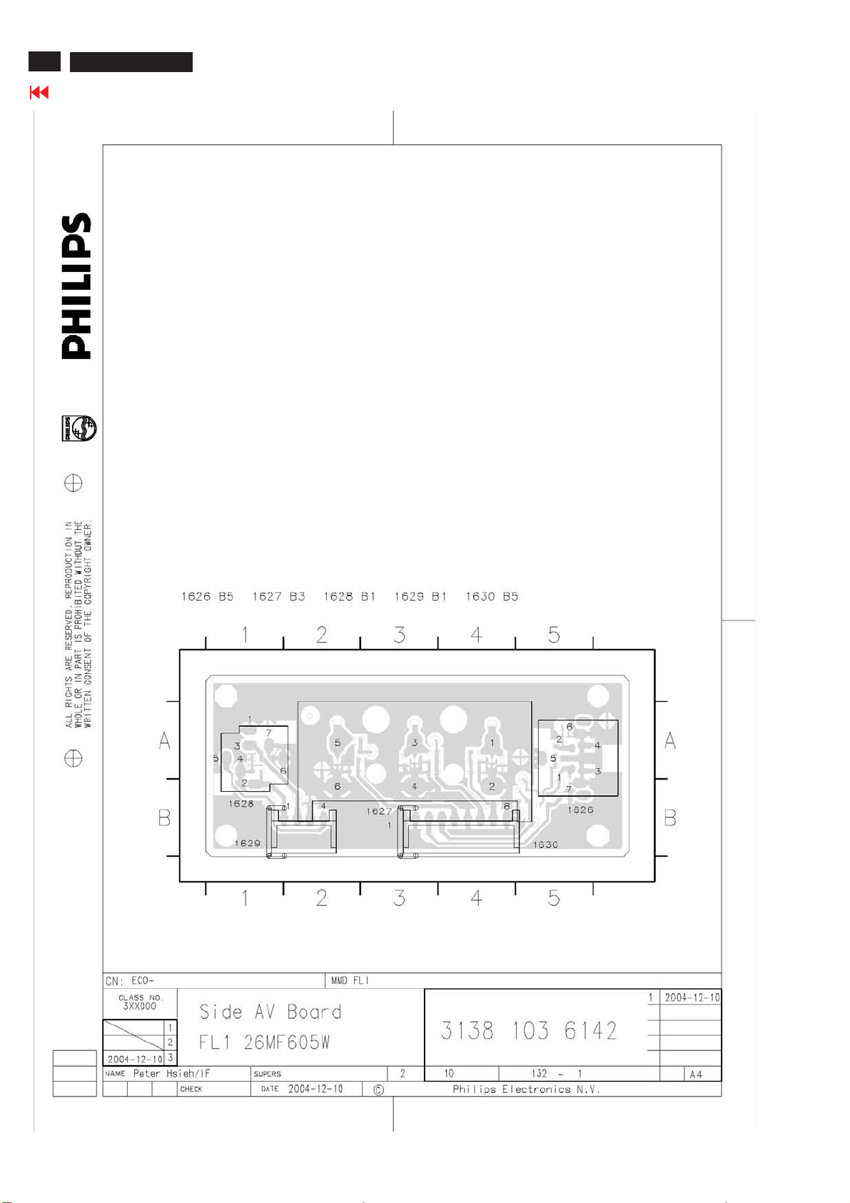
72
26MF605W/17
Go to cover page
SIDE AV Board C.B.A-1
Page 73
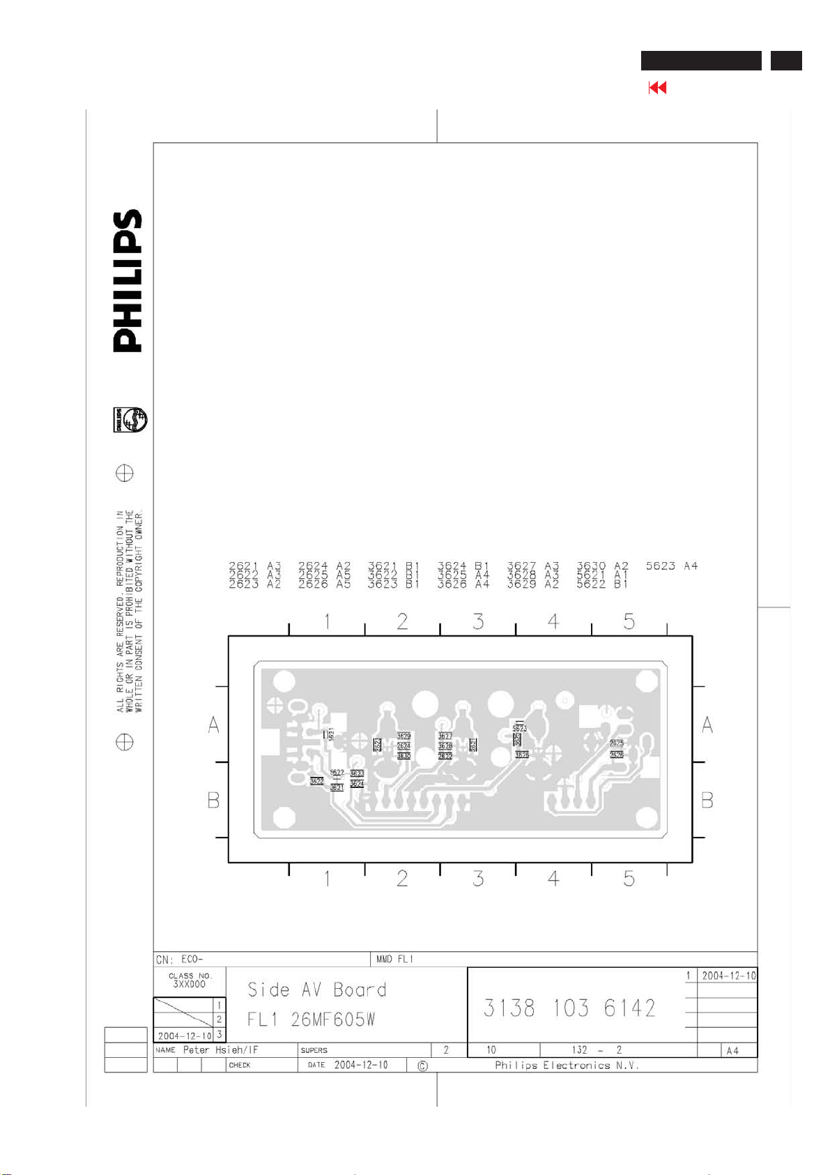
SIDE AV Board C.B.A-2
26MF605W/17
Go to cover page
73
Page 74
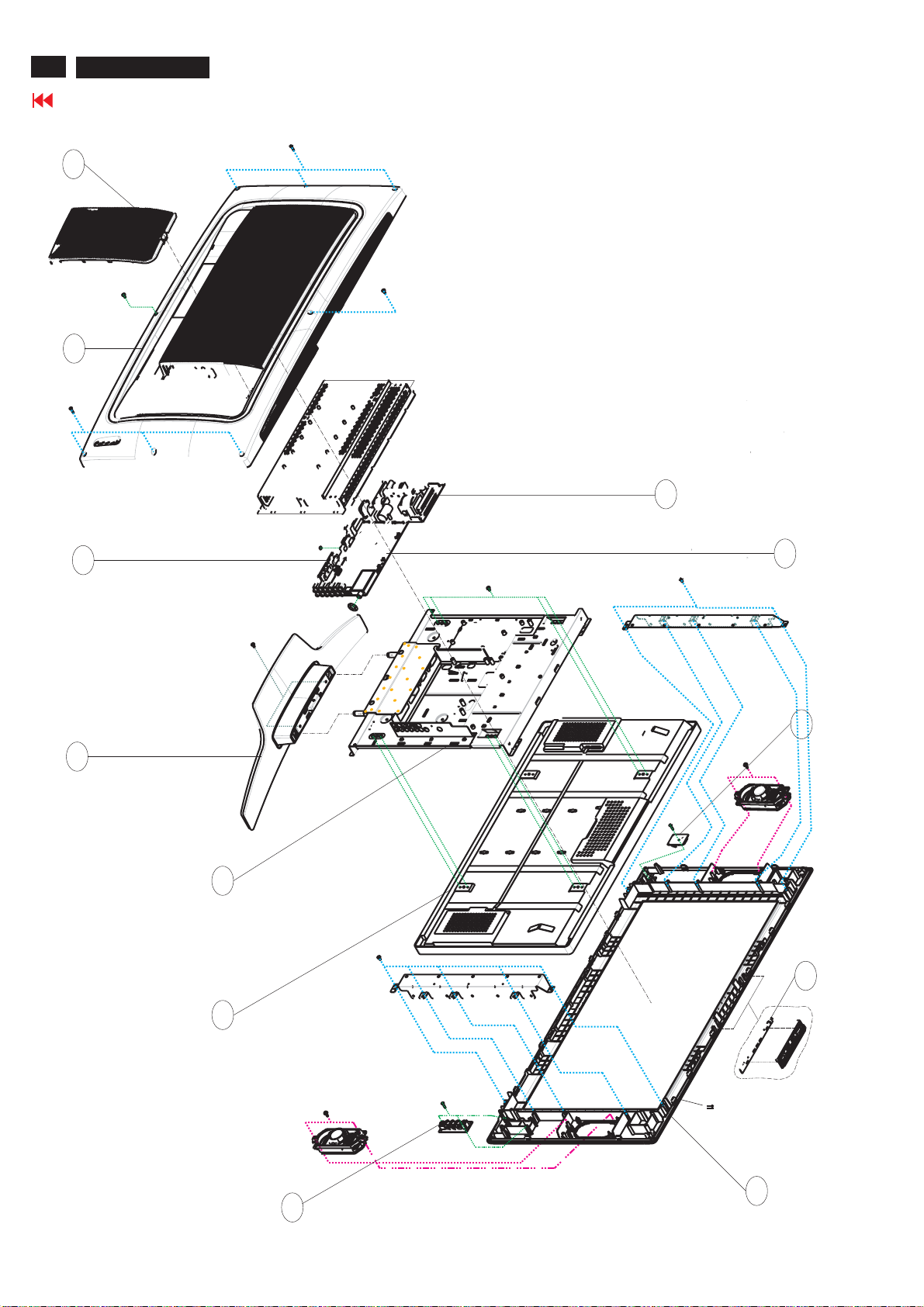
74
26MF605W/17
Go to cover page
41
313815415011
DOOR-CABLE
40
313815415001
BACK COVER
Exploded View
1052
1056
313815861021
HD PCB ASSY(FL1-NA)
7
313815758391
BASE ASSY
51
313815758841
MAIN FRAME ASSY
1050
313815859161
POWER ASSY
1051
313815861141
1053
1054
SCALER PCB ASSY(LPL 26)
313815860811
IR PCB ASSY
313815860881
KEY BOARD ASSY
823827717391
LCD LC260WX2 (series)
313815861031
1055
SIDE AV PCB ASSY(FL1)
11
313815758361
BEZEL ASSY
Page 75
Spare/Recommended Parts List
26MF605W/17
Go to cover page
75
Model: 26MF605W/17(LG) 12NC: 8639 000 16053
Mechanical Parts
7 313815758391 BASE ASSY
11 313815758361 BEZEL ASSY
30 313815415051 BEZEL
31 313815414921 LENS-IR
32 313815414911 POWER BUTTON
40 313815415001 BACK COVER
41 313815415011 DOOR-CABLE
51 313815758841 MAIN FRAME ASSY
91 313815414931 CONTROL BUTTON
132 313815415521 DOOR BASE
1180 313815861171 MAIN FRAME+WIRE ASSY 26"
1411 313815861221 SDRAM ASSY(ISSI)7411,7412
Packing Parts
450 313815639411 CARTON
451 313815639401 CUSHION-L
452 313815639391 CUSHION-R
453 313815640041 P.E. BAG(1000 x 600)
457 313815640051 P.E. BAG(800 X 350)
458 313815636361 P.E.BAG 275x320 mm
Accessory
145 313815523441 OWNER'S MANUAL
1172 313818870491 MAINSCORD UL 10A 1M8 DET B
miscellanea
291 313815566111 LABEL
292 313815566111 LABEL
615 313811708231 HEX CODE OF F/W (NO MATL REQ)
1001 242202518823 CON V 10P M 2.00 63390
1061 823827716541 AC INLET 7014
1062 242208600208 FUSE 5X20 HT 4A 250V IEC
1071 243803100099 CON V 2P M 2.50 63171
1088 242202518904 CON V 12P M 2.50 64842
1089 242202518903 CON V 10P M 2.50 64840
1101 242203300374 SOC DVI H 29P F 1.91DVI-I
1104 243803100428 SOC CINCH H 2P F 2L1 WHRD
1114 242202518432 SOC SUBD H 15P F SBFR
1175 908210090002 BAT ZNC 1.5V 820MAH AA 2-PAC
1176 823827717511 REMOTE CONTROL RC1112713/17
1185 823827717541 LSP 8R 5W OPN FU1R O57X126Y
1186 823827717541 LSP 8R 5W OPN FU1R O57X126Y
1251 313815859171 DIODE ASSY GBU6J 6051
1252 313815859181 DIODE ASSY STTH5L06 6052
1253 313815859191 DIODE ASSY( 6071,6076)
1254 313815859211 POW TRANS ASSY 7057/ 7062
1301 243854300089 RES XTL SM 24M576 16P HC49/S
1401 243854300086 RES XTL SM 14M318 18P HC49/S
1402 242202518804 CON V 30P M 1.25 SM 60948
1501 242202518819 CON V 7P M 2.00 63387
1502 242254301508 RES XTL SM 11M059 20P SMD-49
1503 242202518818 CON V 6P M 2.00 63386
1504 242202518814 CON V 2P M 2.00 63382
1509 243803100435 SOC IC V 8P F 2.54 DIL
1601 242202605733 SOC CINCH H 2P F 1L2 WHRD
1602 242202605453 SOC CINCH H 3P F 1L3 RDBUGR
1608 313819874751 CBLE-017 7/50/7-917 AWG28
1627 242202605546 SOC CINCH H 3P F 1L3 YEWHRD
1628 823827716501 MINIATURE JACK 5102-84V-021-5
1630 313818872301 CON BM H 8P M 2.5 A2502WR2
1714 823827716601 CHINCH CONNECTOR 69444
1715 242202605554 SOC CINCH H 8P F 2L4
1716 242202518816 CON V 4P M 2.00 63384
1717 242202518819 CON V 7P M 2.00 63387
1718 242202518821 CON V 8P M 2.00 63388
1731 242254301372 RES XTL SM 18M432 16P HC49/S
1811 313914722661 FRONTEND FQ1236/F H-5
1822 242202518814 CON V 2P M 2.00 63382
1902 243812800224 SWI PUSH 2P 0.2A 20V SFPC12
1903 242212803035 SWI TACT SM 1P 1POS SKQGAB
1904 242212803035 SWI TACT SM 1P 1POS SKQGAB
1906 242212803035 SWI TACT SM 1P 1POS SKQGAB
1907 242212803035 SWI TACT SM 1P 1POS SKQGAB
1908 242212803035 SWI TACT SM 1P 1POS SKQGAB
1921 823827716481 CON BM H2P M1.25
4444 313810610445 CD ROM - SERVICE MANUAL
4444 313810610446 SERVICE MANUAL
8055 313819874741 CBLE-390 10/110/10-020 AWG26
8161 313819874761 CBLE-001 2/330/2-012 AWG28
8162 313819874771 CBLE-016 6/540/6-016 AWG28
8163 313819874781 CBLE-018 8/335/8 -388 AWG28
8164 313819874791 CBLE-014 4/490/4 -384 AWG28
8165 313819874801 CBLE FAST/700/3 -123 AWG28
8166 313819874811 CBLE FAST/440/2 -392 AWG26
8167 313819874821 CBLE -392 12/580/12-022 AWG26
8174 313819874731 CBLE-130 30/260/30-033 AWG28
LCD Panel
1050 823827717391 LCD LC260WX2 (series)
PCB Assy
1051 313815861141 SCALER PCB ASSY(LPL 26)
1052 313815859161 POWER ASSY
1053 313815860811 IR PCB ASSY
1054 313815860881 KEY BOARD ASSY
1055 313815861031 SIDE AV PCB ASSY(FL1)
1056 313815861021 HD PCB ASSY(FL1-NA)
PCB Assy
1051 313815861141 SCALER PCB ASSY(LPL 26)
2001 202203100207 ELCAP SM RVS 16V 10U PM20
2003 203803513313 ELCAP RGA 25V S 100U PM20
2004 223858619812 CER2 0603 Y5V 50V 100N P8020
2005 223878616641 CER2 0603 X7R 16V 22N PM10
2006 223886715221 CER1 0603 NP0 50V 220P PM5
2007 202203100074 ELCAP KM 16V S 1000U PM20
2009 202055296507 CER2 1206 Y5V 10V 10U P8020
2010 202203100074 ELCAP KM 16V S 1000U PM20
2011 202203100074 ELCAP KM 16V S 1000U PM20
2013 202203100074 ELCAP KM 16V S 1000U PM20
2014 223858115649 CER2 1206 X7R 50V 100N PM10
2015 203803511407 ELCAP REA 35V S 100U PM20
2016 223886715221 CER1 0603 NP0 50V 220P PM5
2018 223886715221 CER1 0603 NP0 50V 220P PM5
2019 223858619807 CER2 0603 Y5V 50V 22N P8020
2020 223891619849 CER2 0603 Y5V 25V 100N P8020
2039 223858619807 CER2 0603 Y5V 50V 22N P8020
2040 203803513313 ELCAP RGA 25V S 100U PM20
2102 223878615649 CER2 0603 X7R 16V 100N PM10
2103 223886715331 CER1 0603 NP0 50V 330P PM5
2104 223886715331 CER1 0603 NP0 50V 330P PM5
2105 223878615649 CER2 0603 X7R 16V 100N PM10
2106 223886715331 CER1 0603 NP0 50V 330P PM5
2107 223886715331 CER1 0603 NP0 50V 330P PM5
2121 223886715109 CER1 0603 NP0 50V 10P PM5
2122 223886715101 CER1 0603 NP0 50V 100P PM5
2123 223886715568 CER1 0603 NP0 50V 5P6 PM0P5
2124 223886715568 CER1 0603 NP0 50V 5P6 PM0P5
2125 223886715568 CER1 0603 NP0 50V 5P6 PM0P5
2126 223878615649 CER2 0603 X7R 16V 100N PM10
2127 223891619849 CER2 0603 Y5V 25V 100N P8020
2128 223886715331 CER1 0603 NP0 50V 330P PM5
2129 223886715331 CER1 0603 NP0 50V 330P PM5
2130 223886715331 CER1 0603 NP0 50V 330P PM5
2132 223886715331 CER1 0603 NP0 50V 330P PM5
2134 223886715339 CER1 0603 NP0 50V 33P PM5
2135 202055296507 CER2 1206 Y5V 10V 10U P8020
2301 223878616641 CER2 0603 X7R 16V 22N PM10
2303 223878616641 CER2 0603 X7R 16V 22N PM10
2304 223878616641 CER2 0603 X7R 16V 22N PM10
2305 223878616641 CER2 0603 X7R 16V 22N PM10
2306 223878616641 CER2 0603 X7R 16V 22N PM10
2308 223878616641 CER2 0603 X7R 16V 22N PM10
2309 223878616641 CER2 0603 X7R 16V 22N PM10
2311 223878616641 CER2 0603 X7R 16V 22N PM10
2312 223878616641 CER2 0603 X7R 16V 22N PM10
2315 223878616641 CER2 0603 X7R 16V 22N PM10
2317 223878616641 CER2 0603 X7R 16V 22N PM10
2318 223878616641 CER2 0603 X7R 16V 22N PM10
2319 223878616641 CER2 0603 X7R 16V 22N PM10
2320 223878616641 CER2 0603 X7R 16V 22N PM10
2321 223886715279 CER1 0603 NP0 50V 27P PM5
2322 223886715279 CER1 0603 NP0 50V 27P PM5
2323 223878616641 CER2 0603 X7R 16V 22N PM10
2324 203803511203 ELCAP REA 16V S 100U PM20
2325 223878615649 CER2 0603 X7R 16V 100N PM10
2326 223878615649 CER2 0603 X7R 16V 100N PM10
2327 223878615649 CER2 0603 X7R 16V 100N PM10
2328 223878615649 CER2 0603 X7R 16V 100N PM10
2329 223878615649 CER2 0603 X7R 16V 100N PM10
2330 223878615649 CER2 0603 X7R 16V 100N PM10
2331 223878615649 CER2 0603 X7R 16V 100N PM10
2332 223878615649 CER2 0603 X7R 16V 100N PM10
2333 223878615649 CER2 0603 X7R 16V 100N PM10
2334 223878615649 CER2 0603 X7R 16V 100N PM10
2335 202055296507 CER2 1206 Y5V 10V 10U P8020
2336 202002191726 ELCAP SM RVS 16V 47U PM20
2337 223878615649 CER2 0603 X7R 16V 100N PM10
2338 223878615649 CER2 0603 X7R 16V 100N PM10
2339 223878615649 CER2 0603 X7R 16V 100N PM10
2340 223878616641 CER2 0603 X7R 16V 22N PM10
2401 223878615649 CER2 0603 X7R 16V 100N PM10
2402 223858615636 CER2 0603 X7R 50V 10N PM10
2403 223878615649 CER2 0603 X7R 16V 100N PM10
2404 202002191726 ELCAP SM RVS 16V 47U PM20
2405 202055296507 CER2 1206 Y5V 10V 10U P8020
2406 223878615649 CER2 0603 X7R 16V 100N PM10
2407 223878615649 CER2 0603 X7R 16V 100N PM10
2408 223878615649 CER2 0603 X7R 16V 100N PM10
2409 223878615649 CER2 0603 X7R 16V 100N PM10
2410 223878615649 CER2 0603 X7R 16V 100N PM10
2411 223878615649 CER2 0603 X7R 16V 100N PM10
2412 223878615649 CER2 0603 X7R 16V 100N PM10
2413 202055296507 CER2 1206 Y5V 10V 10U P8020
2414 223878615649 CER2 0603 X7R 16V 100N PM10
2415 223878615649 CER2 0603 X7R 16V 100N PM10
2416 223878615649 CER2 0603 X7R 16V 100N PM10
2417 223878615649 CER2 0603 X7R 16V 100N PM10
2418 223878615649 CER2 0603 X7R 16V 100N PM10
2419 223878615649 CER2 0603 X7R 16V 100N PM10
2420 202055296507 CER2 1206 Y5V 10V 10U P8020
2421 223878615649 CER2 0603 X7R 16V 100N PM10
2422 223878615649 CER2 0603 X7R 16V 100N PM10
2423 223878615649 CER2 0603 X7R 16V 100N PM10
2424 223878615649 CER2 0603 X7R 16V 100N PM10
2425 202055296507 CER2 1206 Y5V 10V 10U P8020
2426 223878615649 CER2 0603 X7R 16V 100N PM10
2427 223878615649 CER2 0603 X7R 16V 100N PM10
2428 202055296507 CER2 1206 Y5V 10V 10U P8020
2429 223878615649 CER2 0603 X7R 16V 100N PM10
2430 223878615649 CER2 0603 X7R 16V 100N PM10
2431 223878615649 CER2 0603 X7R 16V 100N PM10
2432 223878615649 CER2 0603 X7R 16V 100N PM10
2433 223878615645 CER2 0603 X7R 16V 47N PM10
2434 223878615645 CER2 0603 X7R 16V 47N PM10
2435 223878615645 CER2 0603 X7R 16V 47N PM10
2436 223891611549 CER1 0603 NP0 25V 1N PM5
2437 223878615645 CER2 0603 X7R 16V 47N PM10
2438 223878615645 CER2 0603 X7R 16V 47N PM10
2439 223878615645 CER2 0603 X7R 16V 47N PM10
2440 223878615645 CER2 0603 X7R 16V 47N PM10
2441 223891611549 CER1 0603 NP0 25V 1N PM5
2442 223878615645 CER2 0603 X7R 16V 47N PM10
2443 223858615636 CER2 0603 X7R 50V 10N PM10
2444 223878615649 CER2 0603 X7R 16V 100N PM10
2445 223886715229 CER1 0603 NP0 50V 22P PM5
2446 223886715229 CER1 0603 NP0 50V 22P PM5
2447 223886715339 CER1 0603 NP0 50V 33P PM5
2448 223878615649 CER2 0603 X7R 16V 100N PM10
2449 223878615649 CER2 0603 X7R 16V 100N PM10
2450 223878615649 CER2 0603 X7R 16V 100N PM10
2451 223878615645 CER2 0603 X7R 16V 47N PM10
2452 223878619854 CER2 0603 Y5V 16V 220N P8020
2453 223886715181 CER1 0603 NP0 50V 180P PM5
Page 76
76
26MF605W/17
Go to cover page
2461 223878615649 CER2 0603 X7R 16V 100N PM10
2462 223878615649 CER2 0603 X7R 16V 100N PM10
2463 202055296507 CER2 1206 Y5V 10V 10U P8020
2464 202055296507 CER2 1206 Y5V 10V 10U P8020
2465 223878615649 CER2 0603 X7R 16V 100N PM10
2466 223878615649 CER2 0603 X7R 16V 100N PM10
2467 223878615649 CER2 0603 X7R 16V 100N PM10
2468 223878615649 CER2 0603 X7R 16V 100N PM10
2469 202055296507 CER2 1206 Y5V 10V 10U P8020
2501 223878615649 CER2 0603 X7R 16V 100N PM10
2502 223878615649 CER2 0603 X7R 16V 100N PM10
2503 223858615623 CER2 0603 X7R 50V 1N PM10
2504 223886715229 CER1 0603 NP0 50V 22P PM5
2505 223886715229 CER1 0603 NP0 50V 22P PM5
2506 223878615649 CER2 0603 X7R 16V 100N PM10
2508 202055296507 CER2 1206 Y5V 10V 10U P8020
2509 223886715109 CER1 0603 NP0 50V 10P PM5
2510 223858615636 CER2 0603 X7R 50V 10N PM10
2511 223858015636 CER2 0805 X7R 50V 10N PM10
2512 223886715101 CER1 0603 NP0 50V 100P PM5
2513 223858615636 CER2 0603 X7R 50V 10N PM10
2514 223858615636 CER2 0603 X7R 50V 10N PM10
2515 223858615636 CER2 0603 X7R 50V 10N PM10
2516 223886715101 CER1 0603 NP0 50V 100P PM5
2518 223878615649 CER2 0603 X7R 16V 100N PM10
2541 223878615649 CER2 0603 X7R 16V 100N PM10
2542 223878615649 CER2 0603 X7R 16V 100N PM10
2543 223878615649 CER2 0603 X7R 16V 100N PM10
2544 223878615649 CER2 0603 X7R 16V 100N PM10
2545 223878615649 CER2 0603 X7R 16V 100N PM10
2546 223878615649 CER2 0603 X7R 16V 100N PM10
2547 223878615649 CER2 0603 X7R 16V 100N PM10
2548 223878615649 CER2 0603 X7R 16V 100N PM10
2549 223878615649 CER2 0603 X7R 16V 100N PM10
2550 223878615649 CER2 0603 X7R 16V 100N PM10
2551 223878615649 CER2 0603 X7R 16V 100N PM10
2552 223878615649 CER2 0603 X7R 16V 100N PM10
2553 223878615649 CER2 0603 X7R 16V 100N PM10
2554 223878615649 CER2 0603 X7R 16V 100N PM10
2555 223878615649 CER2 0603 X7R 16V 100N PM10
2556 223878615649 CER2 0603 X7R 16V 100N PM10
2557 223878615649 CER2 0603 X7R 16V 100N PM10
2558 223878615649 CER2 0603 X7R 16V 100N PM10
2559 223878615649 CER2 0603 X7R 16V 100N PM10
2560 223878615649 CER2 0603 X7R 16V 100N PM10
2561 223878615649 CER2 0603 X7R 16V 100N PM10
2562 223878615649 CER2 0603 X7R 16V 100N PM10
2563 223878615649 CER2 0603 X7R 16V 100N PM10
2564 223878615649 CER2 0603 X7R 16V 100N PM10
2566 223886715339 CER1 0603 NP0 50V 33P PM5
2701 223886715331 CER1 0603 NP0 50V 330P PM5
2702 223886715331 CER1 0603 NP0 50V 330P PM5
2703 223886715331 CER1 0603 NP0 50V 330P PM5
2704 223886715331 CER1 0603 NP0 50V 330P PM5
2705 223886715331 CER1 0603 NP0 50V 330P PM5
2706 223886715331 CER1 0603 NP0 50V 330P PM5
2707 223886715331 CER1 0603 NP0 50V 330P PM5
2708 223886715331 CER1 0603 NP0 50V 330P PM5
2709 223886715331 CER1 0603 NP0 50V 330P PM5
2711 223886715331 CER1 0603 NP0 50V 330P PM5
2713 223886715331 CER1 0603 NP0 50V 330P PM5
2715 223886715331 CER1 0603 NP0 50V 330P PM5
2731 223824619863 CER2 0603 Y5V 10V 1U P8020
2732 223824619863 CER2 0603 Y5V 10V 1U P8020
2733 223824619863 CER2 0603 Y5V 10V 1U P8020
2734 223824619863 CER2 0603 Y5V 10V 1U P8020
2735 223824619863 CER2 0603 Y5V 10V 1U P8020
2736 223824619863 CER2 0603 Y5V 10V 1U P8020
2737 223824619863 CER2 0603 Y5V 10V 1U P8020
2738 223824619863 CER2 0603 Y5V 10V 1U P8020
2739 223824619863 CER2 0603 Y5V 10V 1U P8020
2740 223824619863 CER2 0603 Y5V 10V 1U P8020
2741 223824619863 CER2 0603 Y5V 10V 1U P8020
2742 223824619863 CER2 0603 Y5V 10V 1U P8020
2743 223824619863 CER2 0603 Y5V 10V 1U P8020
2744 223824619863 CER2 0603 Y5V 10V 1U P8020
2745 223886715479 CER1 0603 NP0 50V 47P PM5
2746 223886715159 CER1 0603 NP0 50V 15P PM5
Spare/Recommended Parts List
2748 223858015649 CER2 0805 X7R 50V 100N PM10
2749 202055296507 CER2 1206 Y5V 10V 10U P8020
2751 223858015649 CER2 0805 X7R 50V 100N PM10
2753 223858015649 CER2 0805 X7R 50V 100N PM10
2754 223824615654 CER2 0603 X7R 10V 220N PM10
2755 202055296507 CER2 1206 Y5V 10V 10U P8020
2756 223858615632 CER2 0603 X7R 50V 4N7 PM10
2757 223858615632 CER2 0603 X7R 50V 4N7 PM10
2758 202055296507 CER2 1206 Y5V 10V 10U P8020
2759 202055296507 CER2 1206 Y5V 10V 10U P8020
2760 223878615649 CER2 0603 X7R 16V 100N PM10
2761 202055296507 CER2 1206 Y5V 10V 10U P8020
2762 202055296507 CER2 1206 Y5V 10V 10U P8020
2763 223824619863 CER2 0603 Y5V 10V 1U P8020
2764 223824619863 CER2 0603 Y5V 10V 1U P8020
2765 223824619863 CER2 0603 Y5V 10V 1U P8020
2766 223824619863 CER2 0603 Y5V 10V 1U P8020
2767 223886715159 CER1 0603 NP0 50V 15P PM5
2768 223886715159 CER1 0603 NP0 50V 15P PM5
2769 223858015649 CER2 0805 X7R 50V 100N PM10
2770 223858015649 CER2 0805 X7R 50V 100N PM10
2771 202055296507 CER2 1206 Y5V 10V 10U P8020
2772 202055296507 CER2 1206 Y5V 10V 10U P8020
2801 223878615649 CER2 0603 X7R 16V 100N PM10
2802 223886715159 CER1 0603 NP0 50V 15P PM5
2803 223878615649 CER2 0603 X7R 16V 100N PM10
2804 223878615649 CER2 0603 X7R 16V 100N PM10
2805 223878615649 CER2 0603 X7R 16V 100N PM10
2806 223878615649 CER2 0603 X7R 16V 100N PM10
2821 223891015649 CER2 0805 X7R 25V 100N PM10
2822 202203100132 ELCAP LZ 25V S 1000U PM20
2823 202203100132 ELCAP LZ 25V S 1000U PM20
2826 223858615636 CER2 0603 X7R 50V 10N PM10
2827 203803513313 ELCAP RGA 25V S 100U PM20
2828 223824619863 CER2 0603 Y5V 10V 1U P8020
2829 223886715101 CER1 0603 NP0 50V 100P PM5
2830 223878615649 CER2 0603 X7R 16V 100N PM10
2831 202055296507 CER2 1206 Y5V 10V 10U P8020
2832 202055296507 CER2 1206 Y5V 10V 10U P8020
2833 223886715101 CER1 0603 NP0 50V 100P PM5
2834 203803513313 ELCAP RGA 25V S 100U PM20
2835 223824619863 CER2 0603 Y5V 10V 1U P8020
2840 223878619854 CER2 0603 Y5V 16V 220N P8020
2841 223878619854 CER2 0603 Y5V 16V 220N P8020
2842 223878619854 CER2 0603 Y5V 16V 220N P8020
2843 223878615649 CER2 0603 X7R 16V 100N PM10
2844 203803513313 ELCAP RGA 25V S 100U PM20
2845 223891619849 CER2 0603 Y5V 25V 100N P8020
2846 223886715101 CER1 0603 NP0 50V 100P PM5
2847 223886715101 CER1 0603 NP0 50V 100P PM5
2848 223891619849 CER2 0603 Y5V 25V 100N P8020
2849 223858119716 CER2 1206 Y5V 50V 470N PM20
2850 223878619854 CER2 0603 Y5V 16V 220N P8020
2851 223878619854 CER2 0603 Y5V 16V 220N P8020
2852 223878615649 CER2 0603 X7R 16V 100N PM10
2853 202203100231 ELCAP SM HV 50V 1U PM20
2854 223891619849 CER2 0603 Y5V 25V 100N P8020
2855 223858615636 CER2 0603 X7R 50V 10N PM10
2856 223886715221 CER1 0603 NP0 50V 220P PM5
2857 202203100182 ELCAP SM RVS 25V 10U PM20
2858 223878619854 CER2 0603 Y5V 16V 220N P8020
2859 202203100231 ELCAP SM HV 50V 1U PM20
2860 223878615649 CER2 0603 X7R 16V 100N PM10
2861 223891619849 CER2 0603 Y5V 25V 100N P8020
2862 223886715101 CER1 0603 NP0 50V 100P PM5
2863 223886715101 CER1 0603 NP0 50V 100P PM5
2864 203803513313 ELCAP RGA 25V S 100U PM20
2865 223891619849 CER2 0603 Y5V 25V 100N P8020
2866 223878615649 CER2 0603 X7R 16V 100N PM10
2867 223858119716 CER2 1206 Y5V 50V 470N PM20
2868 223878619854 CER2 0603 Y5V 16V 220N P8020
2869 223878619854 CER2 0603 Y5V 16V 220N P8020
2873 223878619854 CER2 0603 Y5V 16V 220N P8020
2881 202055296507 CER2 1206 Y5V 10V 10U P8020
2882 202055296507 CER2 1206 Y5V 10V 10U P8020
2883 202055296507 CER2 1206 Y5V 10V 10U P8020
2884 202203100074 ELCAP KM 16V S 1000U PM20
2885 223886715229 CER1 0603 NP0 50V 22P PM5
3001 212211805678 RST SM 0603 RC0603 47K PM5
3002 212211805682 RST SM 0603 RC0603 82K PM5
3003 212211805676 RST SM 0603 RC0603 33K PM5
3004 232270260101 RST SM 0603 RC21 100R PM5
3005 212211805678 RST SM 0603 RC0603 47K PM5
3006 212211805669 RST SM 0603 RC0603 10K PM5
3007 232270260223 RST SM 0603 RC21 22K PM5
3009 212211805676 RST SM 0603 RC0603 33K PM5
3010 212211805667 RST SM 0603 RC0603 6K8 PM5
3011 232270260472 RST SM 0603 RC21 4K7 PM5
3012 232270463002 RST SM 0603 RC22H 3K PM1
3013 232270461003 RST SM 0603 RC22H 10K PM1
3014 213810500082 RST MOX 1W RSS S 0R82 PM5
3015 212211805667 RST SM 0603 RC0603 6K8 PM5
3020 212211805678 RST SM 0603 RC0603 47K PM5
3021 212211805669 RST SM 0603 RC0603 10K PM5
3024 232270260101 RST SM 0603 RC21 100R PM5
3025 232270260101 RST SM 0603 RC21 100R PM5
3030 212211805669 RST SM 0603 RC0603 10K PM5
3031 232270260472 RST SM 0603 RC21 4K7 PM5
3033 232270260101 RST SM 0603 RC21 100R PM5
3034 232270461002 RST SM 0603 RC22H 1K PM1
3035 232270260472 RST SM 0603 RC21 4K7 PM5
3036 232270462001 RST SM 0603 RC22H 200R PM1
3041 232270260101 RST SM 0603 RC21 100R PM5
3042 232270463302 RST SM 0603 RC22H 3K3 PM1
3043 232270463902 RST SM 0603 RC22H 3K9 PM1
3044 232270465602 RST SM 0603 RC22H 5K6 PM1
3045 232270463303 RST SM 0603 RC22H 33K PM1
3101 232270260101 RST SM 0603 RC21 100R PM5
3102 212211805669 RST SM 0603 RC0603 10K PM5
3103 232270260101 RST SM 0603 RC21 100R PM5
3104 232270260101 RST SM 0603 RC21 100R PM5
3105 232270260472 RST SM 0603 RC21 4K7 PM5
3106 232270260472 RST SM 0603 RC21 4K7 PM5
3107 232270260101 RST SM 0603 RC21 100R PM5
3108 232270260102 RST SM 0603 RC21 1K PM5
3111 232270260102 RST SM 0603 RC21 1K PM5
3112 232270260273 RST SM 0603 RC21 27K PM5
3114 232270260102 RST SM 0603 RC21 1K PM5
3115 232270260273 RST SM 0603 RC21 27K PM5
3131 232270260472 RST SM 0603 RC21 4K7 PM5
3132 232270260101 RST SM 0603 RC21 100R PM5
3133 232270260101 RST SM 0603 RC21 100R PM5
3134 232270260472 RST SM 0603 RC21 4K7 PM5
3135 232270260101 RST SM 0603 RC21 100R PM5
3136 232270260472 RST SM 0603 RC21 4K7 PM5
3137 232270260101 RST SM 0603 RC21 100R PM5
3139 232270260472 RST SM 0603 RC21 4K7 PM5
3140 232270260472 RST SM 0603 RC21 4K7 PM5
3141 232270260273 RST SM 0603 RC21 27K PM5
3142 232270260273 RST SM 0603 RC21 27K PM5
3146 232270260101 RST SM 0603 RC21 100R PM5
3149 232270260101 RST SM 0603 RC21 100R PM5
3153 232270260101 RST SM 0603 RC21 100R PM5
3154 212211805642 RST SM 0603 RC0603 75R PM5
3156 232270260102 RST SM 0603 RC21 1K PM5
3157 212211805642 RST SM 0603 RC0603 75R PM5
3158 232270260101 RST SM 0603 RC21 100R PM5
3159 232270260101 RST SM 0603 RC21 100R PM5
3160 232270260102 RST SM 0603 RC21 1K PM5
3161 212211805642 RST SM 0603 RC0603 75R PM5
3162 232270260689 RST SM 0603 RC21 68R PM5
3163 232270260689 RST SM 0603 RC21 68R PM5
3164 232270260689 RST SM 0603 RC21 68R PM5
3305 212211805639 RST SM 0603 RC0603 47R PM5
3306 212211805639 RST SM 0603 RC0603 47R PM5
3307 212211805639 RST SM 0603 RC0603 47R PM5
3308 212211805639 RST SM 0603 RC0603 47R PM5
3311 235003510101 RST NETW SM ARV24 4X100R PM5
3312 235003510101 RST NETW SM ARV24 4X100R PM5
3313 212211805639 RST SM 0603 RC0603 47R PM5
3316 232270260332 RST SM 0603 RC21 3K3 PM5
3317 232270260472 RST SM 0603 RC21 4K7 PM5
3318 232270260472 RST SM 0603 RC21 4K7 PM5
3320 232270260472 RST SM 0603 RC21 4K7 PM5
3321 232270260101 RST SM 0603 RC21 100R PM5
Page 77
Spare/Recommended Parts List
26MF605W/17
Go to cover page
77
3322 232270260101 RST SM 0603 RC21 100R PM5
3402 212211805651 RST SM 0603 RC0603 390R PM5
3403 232270260471 RST SM 0603 RC21 470R PM5
3404 232270260471 RST SM 0603 RC21 470R PM5
3405 232270260101 RST SM 0603 RC21 100R PM5
3407 232270260102 RST SM 0603 RC21 1K PM5
3408 232270461005 RST SM 0603 RC22H 1M PM1
3409 235003510101 RST NETW SM ARV24 4X100R PM5
3410 235003510101 RST NETW SM ARV24 4X100R PM5
3411 212211805635 RST SM 0603 RC0603 10R PM5
3412 212211805639 RST SM 0603 RC0603 47R PM5
3413 235003510229 RST NETW SM ARV24 4X 22R PM5
3414 235003510229 RST NETW SM ARV24 4X 22R PM5
3415 235003510229 RST NETW SM ARV24 4X 22R PM5
3416 235003510229 RST NETW SM ARV24 4X 22R PM5
3417 235003510229 RST NETW SM ARV24 4X 22R PM5
3418 235003510229 RST NETW SM ARV24 4X 22R PM5
3419 235003510229 RST NETW SM ARV24 4X 22R PM5
3420 232270260101 RST SM 0603 RC21 100R PM5
3421 212211805635 RST SM 0603 RC0603 10R PM5
3422 212211805635 RST SM 0603 RC0603 10R PM5
3423 212211805635 RST SM 0603 RC0603 10R PM5
3424 212211805635 RST SM 0603 RC0603 10R PM5
3425 212211805635 RST SM 0603 RC0603 10R PM5
3426 212211805635 RST SM 0603 RC0603 10R PM5
3427 212211805635 RST SM 0603 RC0603 10R PM5
3428 212211805635 RST SM 0603 RC0603 10R PM5
3430 232270260101 RST SM 0603 RC21 100R PM5
3431 235003510229 RST NETW SM ARV24 4X 22R PM5
3432 235003510229 RST NETW SM ARV24 4X 22R PM5
3433 235003510229 RST NETW SM ARV24 4X 22R PM5
3434 235003510229 RST NETW SM ARV24 4X 22R PM5
3435 232270260472 RST SM 0603 RC21 4K7 PM5
3436 232270260472 RST SM 0603 RC21 4K7 PM5
3501 232270461005 RST SM 0603 RC22H 1M PM1
3502 232270260102 RST SM 0603 RC21 1K PM5
3503 232270260102 RST SM 0603 RC21 1K PM5
3504 232270260101 RST SM 0603 RC21 100R PM5
3505 232270260101 RST SM 0603 RC21 100R PM5
3506 232270260332 RST SM 0603 RC21 3K3 PM5
3507 232270260332 RST SM 0603 RC21 3K3 PM5
3508 232270260332 RST SM 0603 RC21 3K3 PM5
3509 232270260101 RST SM 0603 RC21 100R PM5
3510 232270260101 RST SM 0603 RC21 100R PM5
3511 232270260101 RST SM 0603 RC21 100R PM5
3512 212211805647 RST SM 0603 RC0603 220R PM5
3513 212211805647 RST SM 0603 RC0603 220R PM5
3514 212211805647 RST SM 0603 RC0603 220R PM5
3515 212211805647 RST SM 0603 RC0603 220R PM5
3516 232270260332 RST SM 0603 RC21 3K3 PM5
3517 232270260332 RST SM 0603 RC21 3K3 PM5
3518 212211805678 RST SM 0603 RC0603 47K PM5
3523 232270260472 RST SM 0603 RC21 4K7 PM5
3524 232270260472 RST SM 0603 RC21 4K7 PM5
3525 232270260332 RST SM 0603 RC21 3K3 PM5
3527 232270260101 RST SM 0603 RC21 100R PM5
3529 232270260332 RST SM 0603 RC21 3K3 PM5
3530 232270260472 RST SM 0603 RC21 4K7 PM5
3532 232270260472 RST SM 0603 RC21 4K7 PM5
3533 232270260472 RST SM 0603 RC21 4K7 PM5
3536 212211805647 RST SM 0603 RC0603 220R PM5
3537 212211805647 RST SM 0603 RC0603 220R PM5
3538 212211805678 RST SM 0603 RC0603 47K PM5
3539 212211805659 RST SM 0603 RC0603 1K8 PM5
3561 232270260472 RST SM 0603 RC21 4K7 PM5
3566 232270260472 RST SM 0603 RC21 4K7 PM5
3567 232270260101 RST SM 0603 RC21 100R PM5
3568 232270260101 RST SM 0603 RC21 100R PM5
3569 235003510229 RST NETW SM ARV24 4X 22R PM5
3570 235003510229 RST NETW SM ARV24 4X 22R PM5
3571 212211805635 RST SM 0603 RC0603 10R PM5
3573 235003510689 RST NETW SM ARV24 4X 68R PM5
3574 235003510689 RST NETW SM ARV24 4X 68R PM5
3575 235003510689 RST NETW SM ARV24 4X 68R PM5
3576 235003510689 RST NETW SM ARV24 4X 68R PM5
3577 232270260101 RST SM 0603 RC21 100R PM5
3701 212211805639 RST SM 0603 RC0603 47R PM5
3702 232270260279 RST SM 0603 RC21 27R PM5
3703 232270260279 RST SM 0603 RC21 27R PM5
3704 212211805639 RST SM 0603 RC0603 47R PM5
3705 232270260102 RST SM 0603 RC21 1K PM5
3706 232270260279 RST SM 0603 RC21 27R PM5
3708 212211805639 RST SM 0603 RC0603 47R PM5
3711 232270260102 RST SM 0603 RC21 1K PM5
3712 232270260273 RST SM 0603 RC21 27K PM5
3713 232270260279 RST SM 0603 RC21 27R PM5
3714 232270260102 RST SM 0603 RC21 1K PM5
3715 232270260273 RST SM 0603 RC21 27K PM5
3718 212211805642 RST SM 0603 RC0603 75R PM5
3720 212211805631 RST SM 0603 JUMP. MAX 0R05
3721 232270260101 RST SM 0603 RC21 100R PM5
3722 212211805631 RST SM 0603 JUMP. MAX 0R05
3723 232270260101 RST SM 0603 RC21 100R PM5
3724 232270260224 RST SM 0603 RC21 220K PM5
3725 232270260224 RST SM 0603 RC21 220K PM5
3734 232270260102 RST SM 0603 RC21 1K PM5
3735 232270260273 RST SM 0603 RC21 27K PM5
3739 232270260102 RST SM 0603 RC21 1K PM5
3740 232270260273 RST SM 0603 RC21 27K PM5
3743 212211805639 RST SM 0603 RC0603 47R PM5
3748 212211805642 RST SM 0603 RC0603 75R PM5
3749 212211805642 RST SM 0603 RC0603 75R PM5
3756 212211805642 RST SM 0603 RC0603 75R PM5
3766 232270260101 RST SM 0603 RC21 100R PM5
3771 232270260222 RST SM 0603 RC21 2K2 PM5
3772 212211805678 RST SM 0603 RC0603 47K PM5
3773 212211805678 RST SM 0603 RC0603 47K PM5
3774 212211805678 RST SM 0603 RC0603 47K PM5
3775 212211805678 RST SM 0603 RC0603 47K PM5
3776 212211805678 RST SM 0603 RC0603 47K PM5
3777 212211805678 RST SM 0603 RC0603 47K PM5
3778 212211805678 RST SM 0603 RC0603 47K PM5
3779 212211805678 RST SM 0603 RC0603 47K PM5
3780 232270260101 RST SM 0603 RC21 100R PM5
3781 232270260101 RST SM 0603 RC21 100R PM5
3783 212211805669 RST SM 0603 RC0603 10K PM5
3784 212211805669 RST SM 0603 RC0603 10K PM5
3785 232270260101 RST SM 0603 RC21 100R PM5
3786 232270260101 RST SM 0603 RC21 100R PM5
3787 232270260101 RST SM 0603 RC21 100R PM5
3788 232270260101 RST SM 0603 RC21 100R PM5
3789 232270260101 RST SM 0603 RC21 100R PM5
3790 232270260101 RST SM 0603 RC21 100R PM5
3791 232270260273 RST SM 0603 RC21 27K PM5
3792 232270260222 RST SM 0603 RC21 2K2 PM5
3799 232270260101 RST SM 0603 RC21 100R PM5
3801 232270260471 RST SM 0603 RC21 470R PM5
3802 232270260472 RST SM 0603 RC21 4K7 PM5
3806 232270260101 RST SM 0603 RC21 100R PM5
3807 232270260101 RST SM 0603 RC21 100R PM5
3808 212211805635 RST SM 0603 RC0603 10R PM5
3809 213810500082 RST MOX 1W RSS S 0R82 PM5
3810 232270260101 RST SM 0603 RC21 100R PM5
3811 232270260472 RST SM 0603 RC21 4K7 PM5
3812 212211805635 RST SM 0603 RC0603 10R PM5
3813 213811201111 RST SM 0805 RC05 110R PM5
3814 232270260472 RST SM 0603 RC21 4K7 PM5
3815 232270260102 RST SM 0603 RC21 1K PM5
3816 212211805639 RST SM 0603 RC0603 47R PM5
3831 212211805662 RST SM 0603 RC0603 2K7 PM5
3832 212211805662 RST SM 0603 RC0603 2K7 PM5
3833 232270260472 RST SM 0603 RC21 4K7 PM5
3839 212211805669 RST SM 0603 RC0603 10K PM5
3840 232270260223 RST SM 0603 RC21 22K PM5
3841 232270260223 RST SM 0603 RC21 22K PM5
3842 232270260332 RST SM 0603 RC21 3K3 PM5
3843 232270260332 RST SM 0603 RC21 3K3 PM5
3844 232270260223 RST SM 0603 RC21 22K PM5
3845 232270260223 RST SM 0603 RC21 22K PM5
3846 212211805669 RST SM 0603 RC0603 10K PM5
3849 212211805944 RST SM 0603 RC0603 120K PM5
3850 212211805639 RST SM 0603 RC0603 47R PM5
4001 212211805631 RST SM 0603 JUMP. MAX 0R05
4002 212211805631 RST SM 0603 JUMP. MAX 0R05
4401 212211805631 RST SM 0603 JUMP. MAX 0R05
4429 212211805631 RST SM 0603 JUMP. MAX 0R05
4481 212211805631 RST SM 0603 JUMP. MAX 0R05
4502 212211805631 RST SM 0603 JUMP. MAX 0R05
4521 212211805631 RST SM 0603 JUMP. MAX 0R05
4522 212211805631 RST SM 0603 JUMP. MAX 0R05
4523 212211805631 RST SM 0603 JUMP. MAX 0R05
4524 212211805631 RST SM 0603 JUMP. MAX 0R05
4525 212211805631 RST SM 0603 JUMP. MAX 0R05
4526 212211805631 RST SM 0603 JUMP. MAX 0R05
4528 212211805631 RST SM 0603 JUMP. MAX 0R05
4529 212211805631 RST SM 0603 JUMP. MAX 0R05
4532 212211805631 RST SM 0603 JUMP. MAX 0R05
4708 212211805631 RST SM 0603 JUMP. MAX 0R05
4710 212211805631 RST SM 0603 JUMP. MAX 0R05
4712 212211805631 RST SM 0603 JUMP. MAX 0R05
4714 212211805631 RST SM 0603 JUMP. MAX 0R05
4716 212211805631 RST SM 0603 JUMP. MAX 0R05
4782 212211805631 RST SM 0603 JUMP. MAX 0R05
4793 212211805631 RST SM 0603 JUMP. MAX 0R05
4794 212211805631 RST SM 0603 JUMP. MAX 0R05
4795 212211805631 RST SM 0603 JUMP. MAX 0R05
4796 212211805631 RST SM 0603 JUMP. MAX 0R05
4804 212211805631 RST SM 0603 JUMP. MAX 0R05
4809 212211805631 RST SM 0603 JUMP. MAX 0R05
4812 212211805631 RST SM 0603 JUMP. MAX 0R05
4813 212211805631 RST SM 0603 JUMP. MAX 0R05
4814 212211805631 RST SM 0603 JUMP. MAX 0R05
4815 212211805631 RST SM 0603 JUMP. MAX 0R05
4831 212211805631 RST SM 0603 JUMP. MAX 0R05
4833 212211805631 RST SM 0603 JUMP. MAX 0R05
4841 212211805631 RST SM 0603 JUMP. MAX 0R05
5003 313818875771 COI CHOKE 35UH 82M OHM DR10X8
5004 242254945579 IND FXD 1206 EMI 100MHZ 100R
5005 313818875771 COI CHOKE 35UH 82M OHM DR10X8
5006 313818875771 COI CHOKE 35UH 82M OHM DR10X8
5123 242254944194 IND FXD 0805 EMI 100MHZ 200R
5124 242254944194 IND FXD 0805 EMI 100MHZ 200R
5125 242254944194 IND FXD 0805 EMI 100MHZ 200R
5301 242254944194 IND FXD 0805 EMI 100MHZ 200R
5302 242254944527 IND FXD 0603 EMI 100MHZ 600R
5303 242254944527 IND FXD 0603 EMI 100MHZ 600R
5304 242254944527 IND FXD 0603 EMI 100MHZ 600R
5305 242254944527 IND FXD 0603 EMI 100MHZ 600R
5306 242254944527 IND FXD 0603 EMI 100MHZ 600R
5401 242254944197 IND FXD 0805 EMI 100MHZ 220R
5402 242254944197 IND FXD 0805 EMI 100MHZ 220R
5403 242254944197 IND FXD 0805 EMI 100MHZ 220R
5404 242254944197 IND FXD 0805 EMI 100MHZ 220R
5405 242254944197 IND FXD 0805 EMI 100MHZ 220R
5406 242254944197 IND FXD 0805 EMI 100MHZ 220R
5407 242254944197 IND FXD 0805 EMI 100MHZ 220R
5408 242254944197 IND FXD 0805 EMI 100MHZ 220R
5409 242254944197 IND FXD 0805 EMI 100MHZ 220R
5421 242254944194 IND FXD 0805 EMI 100MHZ 200R
5422 242254944194 IND FXD 0805 EMI 100MHZ 200R
5501 242254944197 IND FXD 0805 EMI 100MHZ 220R
5502 242254944197 IND FXD 0805 EMI 100MHZ 220R
5521 242254944197 IND FXD 0805 EMI 100MHZ 220R
5522 242254944197 IND FXD 0805 EMI 100MHZ 220R
5523 242254944197 IND FXD 0805 EMI 100MHZ 220R
5524 242254944197 IND FXD 0805 EMI 100MHZ 220R
5701 242253595853 IND FXD SM 0603 0U10 PM10
5702 242253595853 IND FXD SM 0603 0U10 PM10
5703 242253595853 IND FXD SM 0603 0U10 PM10
5704 242253595853 IND FXD SM 0603 0U10 PM10
5705 242253595853 IND FXD SM 0603 0U10 PM10
5706 242253595853 IND FXD SM 0603 0U10 PM10
5707 242253595853 IND FXD SM 0603 0U10 PM10
5731 242253595853 IND FXD SM 0603 0U10 PM10
5732 242253595853 IND FXD SM 0603 0U10 PM10
5801 242254945579 IND FXD 1206 EMI 100MHZ 100R
5811 243853598058 IND FXD BEAD EMI 100MHZ 80R
5812 242253600782 IND FXD TSL0808 S 33U PM10
5813 242253600782 IND FXD TSL0808 S 33U PM10
5814 242254900126 IND FXD 0805 EMI 100MHZ 120R
5815 242254900126 IND FXD 0805 EMI 100MHZ 120R
5816 242253595853 IND FXD SM 0603 0U10 PM10
Page 78
78
26MF605W/17
Go to cover page
5817 242253595853 IND FXD SM 0603 0U10 PM10
5818 242254900126 IND FXD 0805 EMI 100MHZ 120R
5819 242254900126 IND FXD 0805 EMI 100MHZ 120R
5820 242253600782 IND FXD TSL0808 S 33U PM10
5821 242253600782 IND FXD TSL0808 S 33U PM10
5822 242254900126 IND FXD 0805 EMI 100MHZ 120R
5841 242254945579 IND FXD 1206 EMI 100MHZ 100R
5842 242254945579 IND FXD 1206 EMI 100MHZ 100R
6001 932221745685 DIO REC SM SSA34 (VISH)
6003 932208282668 DIO REC SM SS34-E3 (VISH)
6004 932221745685 DIO REC SM SSA34 (VISH)
6007 932205976685 DIO SIG SM LS4148 (VISH)
6101 932205976685 DIO SIG SM LS4148 (VISH)
6102 932205976685 DIO SIG SM LS4148 (VISH)
6121 932205976685 DIO SIG SM LS4148 (VISH)
6123 932205976685 DIO SIG SM LS4148 (VISH)
6731 932205976685 DIO SIG SM LS4148 (VISH)
7001 932211529668 FET POW SM SI9433DY-E3 (VISH)
7002 932217438685 TRA SIG SM BC847C (KEC0)
7003 934036790115 TRA SIG SM PDTC114EK (PHSE)
7004 932219076668 IC SM L5972D (ST00)
7005 823827716741 LM1117MPX-ADJ
7006 932213067676 IC L78L08ACZ (ST00)
7009 932216638668 FET POW SM SI5441DC-E3 (VISH)
7010 932219076668 IC SM L5972D (ST00)
7012 932219076668 IC SM L5972D (ST00)
7013 934036790115 TRA SIG SM PDTC114EK (PHSE)
7015 934036790115 TRA SIG SM PDTC114EK (PHSE)
7016 934036790115 TRA SIG SM PDTC114EK (PHSE)
7017 932217438685 TRA SIG SM BC847C (KEC0)
7101 932216972682 IC SM AT24C02N-10SC-2.7(ATME)
7122 935245720165 IC SM 74HCT1G14GW (PHSE)
7124 932216972682 IC SM AT24C02N-10SC-2.7(ATME)
7301 932222076668 IC SM AME1117CCGTZ (ST00)
7302 935276561518 IC SM SAA7119E/V2/G (PHSE)
7303 932222077668 IC SM AME1117ECGTZ (ST00)
7401 932222075668 IC SM AME1117BCGTZ (ST00)
7402 932222076668 IC SM AME1117CCGTZ (ST00)
7403 932222013671 IC SM MST51512L-LF (MSTA)
7411 823827716781 1M16-42S16100A1
7412 823827716781 1M16-42S16100A1
7501 932219183685 IC SM LM809M3-2.93 NOPB(NSC0)
7502 313815861121 CPU ASSY
7502 932222010682 IC SM NT68F632ALG (NOVA)
7503 313815861111 EEPROM IC ASSY
7503 932218650682 IC AT24C16A-10PU-2.7 (ATME)
7504 932217438685 TRA SIG SM BC847C (KEC0)
7522 932220476671 IC SM T6TU5XBG-0001(O2)
7523 823827716781 1M16-42S16100A1
7701 932217438685 TRA SIG SM BC847C (KEC0)
7711 932217891668 IC SM M74HC4052RM (ST00)
7712 934036790115 TRA SIG SM PDTC114EK (PHSE)
7713 934036790115 TRA SIG SM PDTC114EK (PHSE)
7714 932220047702 IC SM MSP3440G-QI-B8V3 (MIAS)
7801 933828890215 TRA SIG SM PMBT2369 (PHSE)
7802 932219513668 IC SM M74HC590M (ST00)
7803 932215366668 IC SM CY7C199-15ZC (CYPR)
7804 935187000118 IC SM 74HC573PW (PHSE)
7805 932219513668 IC SM M74HC590M (ST00)
7806 935187000118 IC SM 74HC573PW (PHSE)
7813 935072110115 IC SM TDA1308T/N1 (PHSE)
7814 932222035668 IC SM TPA3005D2PHP (TI00)
7821 933967310685 TRA SIG SM BC848CLG (ONSE)
PCB Assy
1052 313815859161 POWER ASSY
2051 202233000078 CAP MPP 275V S 470N PM10
2052 202055490156 CERSAF CD 250V S 1N PM20
2053 202055490156 CERSAF CD 250V S 1N PM20
2054 202233000078 CAP MPP 275V S 470N PM10
2055 202231800249 CAP MPOL 450V S 2U2 PM5
2056 222291019856 CER2 0805 Y5V 25V 330N P8020
2057 202055296507 CER2 1206 Y5V 10V 10U P8020
2058 223858015636 CER2 0805 X7R 50V 10N PM10
2059 223891015649 CER2 0805 X7R 25V 100N PM10
Spare/Recommended Parts List
2060 823827717681 CAPACITANCE 120U/450V HS
2061 203830250166 CAP MPOL 400V S 10N PM10
2065 223858015643 CER2 0805 X7R 50V 33N PM10
2066 202202000977 ELCAP GS 50V S 6U8 PM20
2067 203803521307 ELCAP GS 25V S 68U PM20
2068 202203100272 ELCAP PF 25V S 47U PM20
2071 202055490158 CERSAF CD 250V S 2N2 PM20
2072 223858015627 CER2 0805 X7R 50V 2N2 PM10
2073 203830150151 CAP PP PPN 100V S 10N PM2
2074 202203100387 ELCAP EB 25V S 2200U PM20
2075 202203100273 ELCAP PF 25V S 100U PM20
2076 223858015649 CER2 0805 X7R 50V 100N PM10
2077 203830150136 CAP PP PPN 100V S 3N3 PM5
2078 203830150159 CAP PP PPN 100V S 12N PM5
2079 202203100362 ELCAP LZ 35V S 1000U PM20
2080 202203100362 ELCAP LZ 35V S 1000U PM20
2081 203803527502 ELCAP KM 50V S 22U PM20
2085 223858015625 CER2 0805 X7R 50V 1N5 PM10
2086 202202000805 ELCAP GS 50V S 2U2 PM20
2087 223858015636 CER2 0805 X7R 50V 10N PM10
2088 223891015649 CER2 0805 X7R 25V 100N PM10
2091 223891015649 CER2 0805 X7R 25V 100N PM10
2092 223891015649 CER2 0805 X7R 25V 100N PM10
3051 212211805971 RST SM 1206 RC1206 270K PM5
3052 212211805971 RST SM 1206 RC1206 270K PM5
3053 212211805971 RST SM 1206 RC1206 270K PM5
3054 232271161824 RST SM 1206 RC01 820K PM5
3055 232271161824 RST SM 1206 RC01 820K PM5
3056 213811201103 RST SM 0805 RC05 10K PM5
3057 232273061333 RST SM 0805 RC11 33K PM5
3058 212210101515 RST CRB CF1/6 A 390R PM5
3059 212010500027 RST MOX 1W RSS A 0R15 PM1
3060 232271161683 RST SM 1206 RC01 68K PM5
3061 213810113228 RST CRB CFR-12 A 2R2 PM5
3062 232273061229 RST SM 0805 RC11 22R PM5
3064 232273463304 RST SM 0805 RC12H 330K PM1
3065 232273463304 RST SM 0805 RC12H 330K PM1
3066 232273463304 RST SM 0805 RC12H 330K PM1
3067 232273466201 RST SM 0805 RC12H 620R PM1
3068 232273465602 RST SM 0805 RC12H 5K6 PM1
3070 232273061102 RST SM 0805 RC11 1K PM5
3074 213811201224 RST SM 0805 RC05 220K PM5
3075 232273061102 RST SM 0805 RC11 1K PM5
3076 232273061471 RST SM 0805 RC11 470R PM5
3077 232273061274 RST SM 0805 RC11 270K PM5
3078 232273061474 RST SM 0805 RC11 470K PM5
3079 213811201331 RST SM 0805 RC05 330R PM5
3080 213811201103 RST SM 0805 RC05 10K PM5
3081 212010500027 RST MOX 1W RSS A 0R15 PM1
3082 213811201151 RST SM 0805 RC05 150R PM5
3083 213810113228 RST CRB CFR-12 A 2R2 PM5
3084 213811201222 RST SM 0805 RC05 2K2 PM5
3085 232273061102 RST SM 0805 RC11 1K PM5
3086 232273061102 RST SM 0805 RC11 1K PM5
3087 213810113334 RST CRB CFR-12 A 330K PM5
3088 232273061229 RST SM 0805 RC11 22R PM5
3089 213811201222 RST SM 0805 RC05 2K2 PM5
3090 232273461002 RST SM 0805 RC12H 1K PM1
3091 232273461803 RST SM 0805 RC12H 18K PM1
3092 213811201101 RST SM 0805 RC05 100R PM5
3093 212210102197 RST CRB CF1/6 A 4K7 PM5
3094 232273061223 RST SM 0805 RC11 22K PM5
3095 232273462202 RST SM 0805 RC12H 2K2 PM1
3096 232273061223 RST SM 0805 RC11 22K PM5
3097 232273061223 RST SM 0805 RC11 22K PM5
3098 213811201103 RST SM 0805 RC05 10K PM5
5051 313816874511 FERRITE BEAD
5052 313816874511 FERRITE BEAD
5053 823827716711 LINE FILTER RING CORE
5054 243853598026 IND FXD BEAD EMI 100MHZ 35R
5055 243853598026 IND FXD BEAD EMI 100MHZ 35R
5056 823827716941 LINE FILTER ET28
5057 823827715741 PFC COIL
5061 242253597072 IND FXD SP0305 A 6U8 PM10
5071 823827715721 POWER TRANSFORMER
5072 243853598026 IND FXD BEAD EMI 100MHZ 35R
5073 243853598026 IND FXD BEAD EMI 100MHZ 35R
5074 823827716731 INDUCTOR 10uH
5075 243853598026 IND FXD BEAD EMI 100MHZ 35R
5076 243853598026 IND FXD BEAD EMI 100MHZ 35R
5077 243853598026 IND FXD BEAD EMI 100MHZ 35R
5078 243853598026 IND FXD BEAD EMI 100MHZ 35R
5079 823827716731 INDUCTOR 10uH
5080 242253600038 IND FXD TSL0808 S 22U PM10
6051 931900263671 BRIDGE GBU6J-E3 (VISH)
6052 932220958687 DIO REC STTH5L06FP (ST00)
6053 933952580685 DIO SIG SM BAV103 (VISH)
6055 932222090673 DIO SUP P6KE250A A (LITO)
6056 932222163673 DIO REC UF1007 A (LITO)
6061 933952580685 DIO SIG SM BAV103 (VISH)
6062 933952580685 DIO SIG SM BAV103 (VISH)
6063 933952580685 DIO SIG SM BAV103 (VISH)
6064 933751660673 DIO REC RGP10D-E3 A (VISH)
6065 933952580685 DIO SIG SM BAV103 (VISH)
6066 933751660673 DIO REC RGP10D-E3 A (VISH)
6067 932222167673 DIO SUP P4KE16A A (LITO)
6071 932219932687 DIO REC STPS10H100CFP (ST00)
6072 933952580685 DIO SIG SM BAV103 (VISH)
6073 933952580685 DIO SIG SM BAV103 (VISH)
6074 933712930673 DIO REG BZX55-C12 A (VISH)
6075 933712760673 DIO REG BZX55-B18 A (VISH)
6076 932219203687 DIO REC STPS20H100CFP (ST00)
6081 933712970673 DIO REG BZX55-C20 A (VISH)
7056 823827716751 PFC CONTROLLER L6562
7057 823827716581 TRANSISTOR 20A 600V STP20NM60
7061 935267356112 IC TEA1507P/N1 (PHSE)
7062 932219657687 FET POW STP10NK80ZFP (ST00)
7063 933953410676 TRA SIG TBC328-40 (TOSJ)
7071 823827717691 TRANSISTOR 45A30V
7072 932214014667 OPT CP TCET1103(G) (VISH)
7073 932208697676 IC TL431ACZ S (ST00)
7074 932214014667 OPT CP TCET1103(G) (VISH)
7075 933705890676 TRA SIG BF422 (TOSJ)
7076 933237790126 TRA SIG BC547C (PHSE)
PCB Assy
1053 313815860811 IR PCB ASSY
2901 223878615649 CER2 0603 X7R 16V 100N PM10
2902 222278019763 CER2 0805 Y5V 16V 1U PM20
2903 223858015636 CER2 0805 X7R 50V 10N PM10
3901 212211805669 RST SM 0603 RC0603 10K PM5
3902 232270260101 RST SM 0603 RC21 100R PM5
3904 212211805647 RST SM 0603 RC0603 220R PM5
3905 212211805647 RST SM 0603 RC0603 220R PM5
6901 313815862261 IR + HOLDER ASSY
6901 932220313667 IR RECEIVER TSOP34136SB1
6902 313815862171 LED + HOLDER ASSY
6902 932214603682 LED VS L-3WYGW (KIEL)
7901 932217439685 TRA SIG SM BC857C (KEC0)
PCB Assy
1054 313815860881 KEY BOARD ASSY
2904 223858615636 CER2 0603 X7R 50V 10N PM10
3906 232270260471 RST SM 0603 RC21 470R PM5
3907 232270260222 RST SM 0603 RC21 2K2 PM5
3909 232270260332 RST SM 0603 RC21 3K3 PM5
3910 232270260472 RST SM 0603 RC21 4K7 PM5
3911 232270260102 RST SM 0603 RC21 1K PM5
PCB Assy
1055 313815861031 SIDE AV PCB ASSY(FL1)
2621 223886715331 CER1 0603 NP0 50V 330P PM5
2622 223886715331 CER1 0603 NP0 50V 330P PM5
2623 223886715331 CER1 0603 NP0 50V 330P PM5
2624 223886715331 CER1 0603 NP0 50V 330P PM5
Page 79
Spare/Recommended Parts List
26MF605W/17
Go to cover page
79
2625 223858615634 CER2 0603 X7R 50V 6N8 PM10
2626 223858615634 CER2 0603 X7R 50V 6N8 PM10
3621 232270260279 RST SM 0603 RC21 27R PM5
3622 212211805639 RST SM 0603 RC0603 47R PM5
3623 232270260279 RST SM 0603 RC21 27R PM5
3624 212211805639 RST SM 0603 RC0603 47R PM5
3625 232270260279 RST SM 0603 RC21 27R PM5
3626 212211805639 RST SM 0603 RC0603 47R PM5
3627 232270260102 RST SM 0603 RC21 1K PM5
3628 232270260273 RST SM 0603 RC21 27K PM5
3629 232270260102 RST SM 0603 RC21 1K PM5
3630 232270260273 RST SM 0603 RC21 27K PM5
5621 242253595853 IND FXD SM 0603 0U10 PM10
5622 242253595853 IND FXD SM 0603 0U10 PM10
5623 242253595853 IND FXD SM 0603 0U10 PM10
PCB Assy
1056 313815861021 HD PCB ASSY(FL1-NA)
2601 223886715331 CER1 0603 NP0 50V 330P PM5
2602 223886715331 CER1 0603 NP0 50V 330P PM5
2603 223886715331 CER1 0603 NP0 50V 330P PM5
2604 223886715331 CER1 0603 NP0 50V 330P PM5
3601 232270260102 RST SM 0603 RC21 1K PM5
3602 232270260273 RST SM 0603 RC21 27K PM5
3603 232270260102 RST SM 0603 RC21 1K PM5
3604 232270260273 RST SM 0603 RC21 27K PM5
3605 212211805642 RST SM 0603 RC0603 75R PM5
3606 212211805642 RST SM 0603 RC0603 75R PM5
3607 212211805642 RST SM 0603 RC0603 75R PM5
5601 242253595853 IND FXD SM 0603 0U10 PM10
5602 242253595853 IND FXD SM 0603 0U10 PM10
5603 242253595853 IND FXD SM 0603 0U10 PM10
Recommended Parts List
7 313815758391 BASE ASSY
11 313815758361 BEZEL ASSY
30 313815415051 BEZEL
31 313815414921 LENS-IR
32 313815414911 POWER BUTTON
40 313815415001 BACK COVER
41 313815415011 DOOR-CABLE
91 313815414931 CONTROL BUTTON
132 313815415521 DOOR BASE
145 313815523441 OWNER'S MANUAL
450 313815639411 CARTON
451 313815639401 CUSHION-L
452 313815639391 CUSHION-R
453 313815640041 P.E. BAG(1000 x 600)
457 313815640051 P.E. BAG(800 X 350)
458 313815636361 P.E.BAG 275x320 mm
615 313811708231 HEX CODE OF F/W (NO MATL REQ)
6007 932205976685 DIO SIG SM LS4148 (VISH)
6101 932205976685 DIO SIG SM LS4148 (VISH)
7004 932219076668 IC SM L5972D (ST00)
7005 823827716741 LM1117MPX-ADJ
7006 932213067676 IC L78L08ACZ (ST00)
7010 932219076668 IC SM L5972D (ST00)
7013 934036790115 TRA SIG SM PDTC114EK (PHSE)
7403 932222013671 IC SM MST51512L-LF (MSTA)
7813 935072110115 IC SM TDA1308T/N1 (PHSE)
7814 932222035668 IC SM TPA3005D2PHP (TI00)
8161 313819874761 CBLE-001 2/330/2-012 AWG28
8163 313819874781 CBLE-018 8/335/8 -388 AWG28
Page 80
80
26MF605W/17
Go to cover page
.26" Multifunction LCD monitor
. PC 15 pins D-SUB analog interface
. PC audio line in with mini-Jack
. TV Tuner, S-Video, RCA AV input/output interface with R/LAudio-in
. DVI digital interface with HDCP support (for TVonly)
. RCA connectors for YPbPr input
.HD/Component YPbPrwithL/R audio input (RCA connector)
. NTSC, PAL TVsystem
. PC graphic auto picture adjustment
GENERAL PRODUCT SPECIFICATION
GENERAL PRODUCT SPECIFICATION
. 14 user modes
. User-friendly OSD menu
. User-friendly remote controller
. Recommend resolution 1280 x 720 non-interlace at 60 Hz
.WXGA 26
. Easy tilt base
. Anti-glare to reduce light reflection
. Power management capability
.VESA standard wall mount kit (option)
" color TFT LCD flat panel
2004-12-20
Peter Hsieh
26" Wide LCD Monitor / TV
TYPE :26MF605W/17
BRAND : Magnavox
2004-12-20
18
8639 000 16053
590
1
Page 81
GENERAL PRODUCT SPECIFICATION(Continued)
CONTENTS
1.0 Foreword
2.0 Product profile
2.1 LCD
2.2 Scanningfrequencies
2.3 Video dot rate
2.4 Power input
2.5 Power consumption
2.6 Dimensions
2.7 Weight
2.8 Side speaker
2.9 Functions
2.10 Ambient temperature
2.11 Regulatory compliance
3.0 Electrical characteristics
3.1 Interface signals cables
3.2 User interface
3.2.1 Keypaddefini tion
3.2.2 Key Functiondefinition
3.2.3 Remote control
3.3 PC, TVrequirement
3.3.1 PC interface
3.3.1.1 Modestoring capacity
3.3.1.2 Horizontal scanning
3.3.1.3 Vertical scanning
3.3.1.4 Inputconnectors
3.3.1.5 Available timings
3.3.2 I/Ointerface
3.3.2.1 TVspecial setting
3.3.3 Electric characteristics
3.3.3.1 PC Signal type
3.3.3.2 TV Signal type
3.3.3.3 PVR output (CVBS output)
3.3.3.4 Headphoneoutput
3.4 Power inputconnection
3.5 Power management
of I/O
26MF605W/17
Go to cover page
81
4.0 Vis ual characteristics
4.1 Test conditions
4.2 PC resolution
4.3 Brightness
4.4 Image size
4.4.1 Actual display size
4.5 Brightness uniformity
4.6 PC white color adjustment
4.7 TVwhite color adjustment
4.8 TVpicture centering
26" Wide LCD Monitor / TV
TYPE :26MF605W/17
BRAND :Magnavox
2004-12-20
Peter Hsieh
2004-12-20
18
8639 000 16053
590
2
Page 82
82
26MF605W/17
Go to cover page
5.0 Mechanical characteristics
6.0 Environmental characteristics
7.0 Reliability
8.0 Quality assurance requirements
9.0 Serviceability
GENERAL PRODUCT SPECIFICATION(Continued)
5.1 Controls
5.2 Unit dimension / weight
5.3 Tilt and swivel base
5.4 Transportation packages
5.4.1 Shipping dimension / weight
5.4.2 Block unit / palletization
6.1 Susceptibility of display to external environment
6.2 Transportation tests
6.3 Display disturbances from external environment
7.1 Mean time between failures
8.1 Acceptance test
1.0 FOREWORD
This specification describes a 26"multifunction LCD Monitor, maximum resolution up to 1280x768/60Hz non-interlaced.
2.0 PRODUCT PROFILE
This 26" TFT LCD monitor/TV can connect to PC sanalogD-SUBandTV s digital signal through DVI-D
connector and it also have TV, Composite Video, S-Video, Component YPbPr , PVR output and HD YPbPr interface.
2.1 LCD
2.1.1. LPL panel
Type NR. : LC260WX2 (LPL panel)
Display area(mm) : 575.769mm x 323.712mm
Number of Pixels : 1366(H) x 768(V)
Pitch ( mm ) : 0.4215(H) x 0.4215(V)
Color pixel arrangement : RGB vertical stripe
Display operating mode : Normally black
Color depth : 16,777,216 colors ( 8 bits)
Brightness (cd/m^2) : 500(Center 1 points, Typ.)
Viewing angle(CR>10) : Viewing angle free(R/L 176(Typ.),U/D 176(Typ.))
Surface treatment : Hard coating(3H),Anti-glare treatment of the front polarize
Electrical interface : LVDS
Response Time(ms, Typ): TrR:7 ,TrD:9(Gray to Gray)
Contrast ratio : Typical 600 : 1
Outline Dimension : 626.0mm(H) x 373.0mm(V) x 44.1mm(D) (Typ.)
Module weight (g) : 5000(Typ.)
Backlight : 18 EEFL
2.2 Scanning frequencies : Hor. : 30 - 50KHz Ver.: 56 - 63 Hz
2.3 Video dot rate : <80 MHz
26" Wide LCD Monitor / TV
TYPE : 26MF605W/17
BRAND : Magnavox
2004-12-20
Peter Hsieh
2004-12-20
18
8639 000 16053
590
3
Page 83
GENERAL PRODUCT SPECIFICATION(Continued)
2.4 Power input : 90 - 264 Vac, 50/60 ± 2Hz
2.5 Power consumption :70W/Typ. ( at PC mode ) ,105W/Typ. ( at TVmode ).
2.6 Unit Dimensions : 820 mm W x 213 mm H x 480 mm D(Incl. Pedestal)
2.7 UnitWeight : 11.5 Kg
2.8 Chin speaker : 2x5W
2.9 Functions:
PC -15 pins D-subanalog interface with audiomini-Jack input (PC line in).
26MF605W/17
Go to cover page
83
TV-DVI-DD
-Tuner, Aerial input.
-ComponentYPbPr inputand Composite Video inputsharewith the same audio.
-HD/ComponentYPbPr inputand audio inputwith RCA jack.
-Side
-PVR output (Composite Video and Audiooutput).
-Headphoneoutput.
2.10 Ambient temperature:
2.11 Regulatory compliance :
FCC, EPA, UL, CSA, TUV/GS, TUV/ERG, CE, C-Tick, SEMKO,
Nutek,
EN60065/IEC60065, EN55013, EN55020, EN55022, EN55024, EN60555-2,
EN61000-3-2
igital interface (Support HDCP) with RCA jack L/R audio input.
composite video inputand S-Video inputsharewith the same audio.
5~35°C
MPRII,BSMI, PSB, CB, PZ1, ISO13406-2. EN60950/IEC60950,
3.0 Electrical characteri stics
3.1 Interface signals cables
VGAInterface Cable (option) Length : 1.8 M +/- 50 mm
DVI-DCable (option) Length : 1.8 M +/- 50 mm
Stereo RCA R/L audiocable(option) Length:1.5M+/-50mm
S-video cable (option)
AV cable (option) Length : 1.5M +/- 50 mm
Mini Jack stereo cable (option) Length : 1.5 M +/- 50 mm
YPbPrcable(option) Length : 1.5M +/- 50mm
Power cordLength:1.8M+/-50mm
3.2 User interface
On screendisplay user control viakeypad and remote control for PC and TV OSD.
26" Wide LCD Monitor / TV
TYPE :26MF605W/17
BRAND :Magnavox
2004-12-20
Peter Hsieh
2004-12-20
Length:1.5M+/-50mm
18
590
8639 000 16053
4
Page 84
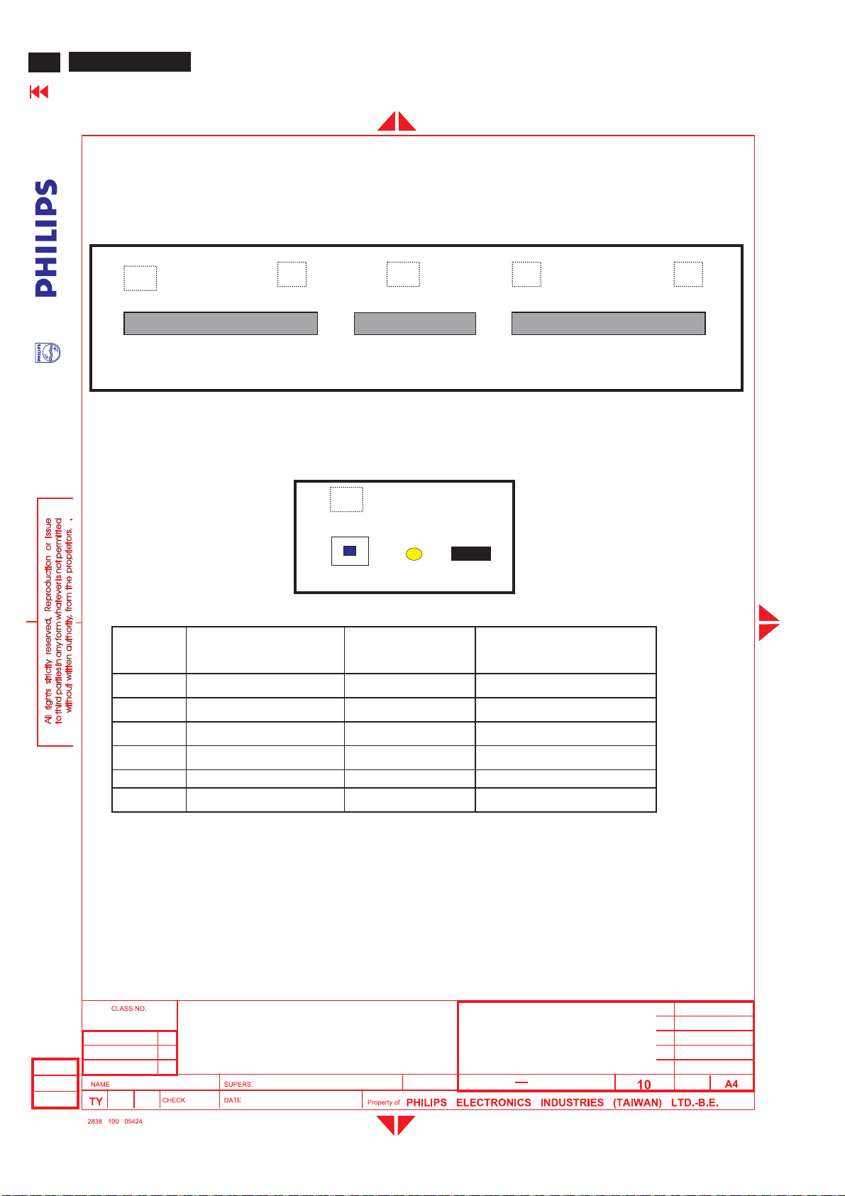
84
26MF605W/17
Go to cover page
3.2.1 Keypad definition
GENERAL PRODUCT SPECIFICATION(Continued)
Top Control Panel
B
- Volume +
C D E F
Menu
- Channel +
RightLeft
Front Control Panel
A
Power SW
3.2.2 Key Function definition:
Key Function VGA mode TV/video mode
<A> Power DC Power DC Power
<B> Left Left/Volume down Left/Volume down
<C> Right Right/Volume up Right/Volume up
<D> Menu Enter /Exit OSD menu Enter /Exit OSD menu
<E> Menu Down/channel down Menu line Down Menu Down/Channel Down
<F> Menu Up/Channel up Menu line Up Menu Up/Channel up
Power
LED
RC sensor
UpDown
1. Press "MENU" key to call main menu.
2. By "Up/Down" to select function and "Left/Right" to adjust.
3. "Left/Right" also is Volume Hot Key (TV and PC mode).
4. "Up/Down" also is Channel Hot Key (TV mode).
5. Press hot Key <B> and <C> can auto-adjust picture position, phase and clock in PC mode.
Power LED:
Normal working: Green
Power saving: Amber
26" Wide LCD Monitor / TV
2004-12-20
Peter Hsieh
TYPE : 26MF605W/17
BRAND : Magnavox
18
2004-12-20
8639 000 16053
590
5
Page 85
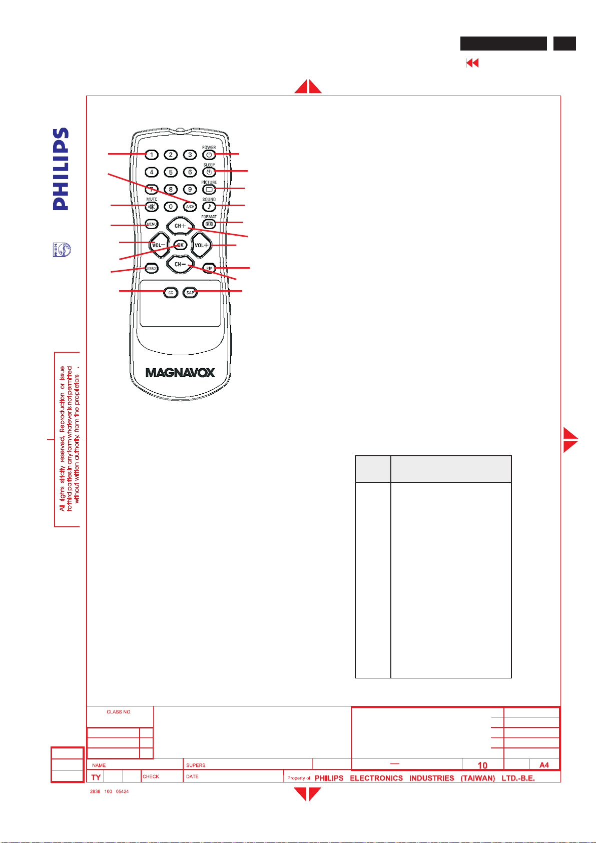
GENERAL PRODUCT SPECIFICATION(Continued)
3.2.3 Remote control
1.Power : Power On/Standby
2
4
1
18
17
316
5
6
15
14
13
7
8
12
11
910
2.Numerica keys : (0~9) ,Channel setting
3.Mute : Sound mute function
4.Prev-CH:Recall previous CH
5.Menu :Main menu select and OKkey
6.VOL-:Left/Volume Down
7.OK:OK
8.Source : Source select
9.Closed cap. : Closed caption on/off
10.SAP(2
11.CH- : Down/Channel Down
12.PIP : PIP size select (Small/Medium/Large/PBP)
13.VOL+:Right/Volume Up
14.CH+ : Up/ Channel Up
15.Display Format : Select display format
16.Smart Sound : Select sound effect
17.Smart Picture : Select picture effect
18.Sleep Timer : Sleep timer 15,30,60,120,180,240 OFF
nd
audio) : Sound select
26MF605W/17
Go to cover page
85
All PC or TV OSD menu function could be accomplished by remote control.
3.3 PC and TVrequirement
3.3.1 PC interface
3.3.1.1 Modestoringcapacity
3.3.1.2 Horizontal scanning
3.3.1.3 Vertical scanning
3.3.1.4 Inputconnectors
Pre-set : 6
User modes : 8
Syncpolarity : Positive or Negative
Scanningfrequency : 30 - 50 KHz
Sync polarity : Positive or Negative
Scanningf
Inputanalog D-subconnector pin assignment
requency : 56 - 63 Hz
-1.8m15Pins, D-submalewith DDC2B Pin assignments.
PIN
No.
SIGNAL b(PC)
1 Red
2Green
3Blue
4 Self test
5GND
6 Red GND
7Green GND
8BlueGND
9+5V(Supply from PC)
10 SyncGND
11 GND
12 Bi-directional data
13 H-sync
14 V-sync
15 Data clock
2004-12-20
Peter Hsieh
26" Wide LCD Monitor / TV
TYPE :26MF605W/17
BRAND :Magnavox
2004-12-20
18
8639 000 16053
590
6
Page 86
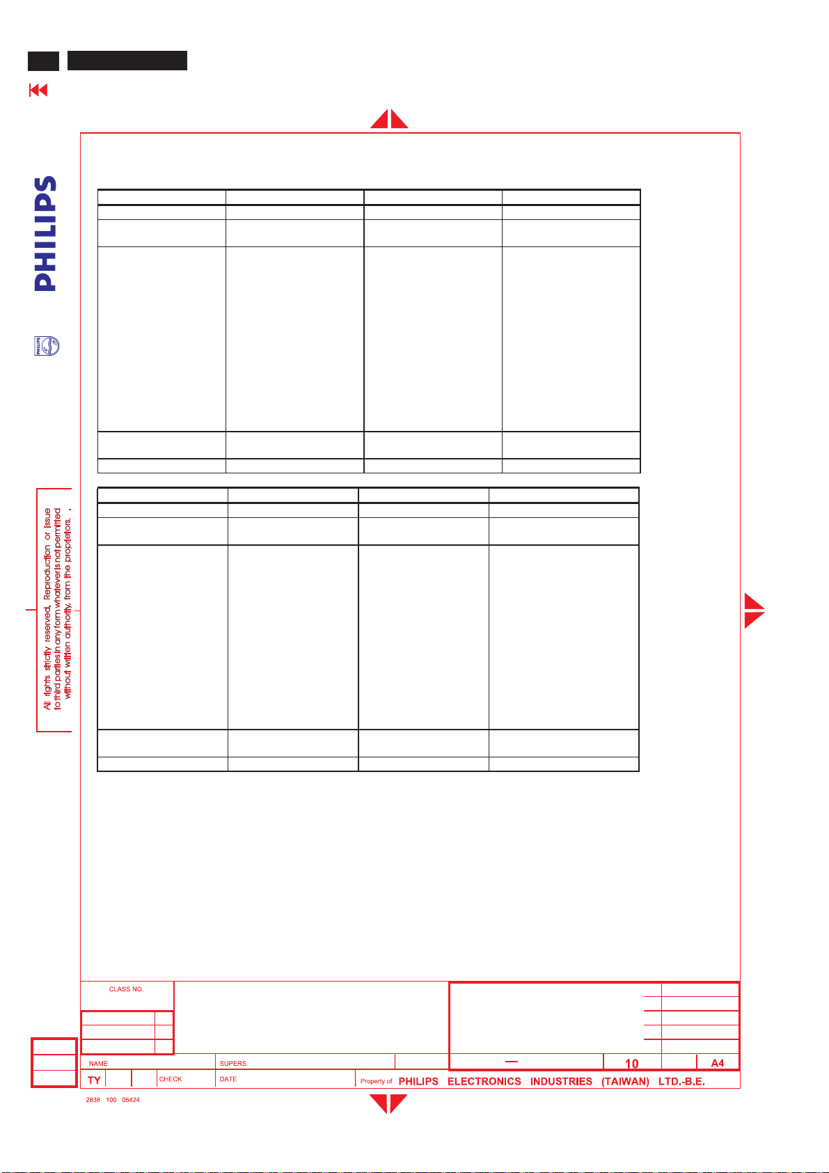
86
26MF605W/17
Go to cover page
GENERAL PRODUCT SPECIFICATION(Continued)
3.3.1.5 Available timings
MODE NO. 1 2 3
RESOLUTION 640 x 480 800 x 600 800 x 600
Dot clock(MHz) 25.175 36.000 40.000
f h 31.469kHz 35.156kHz 37.879kHz
A ( us ) 31.778 (800 dots) 28.44 (1024 dots) 26.40 (1056 dots)
B ( us ) 3.813 ( 96 dots) 2.000 ( 72 dots) 3.200 ( 128 dots)
C ( us ) 1.907 ( 48 dots) 3.556 ( 128 dots) 2.200 ( 88 dots)
D ( us ) 25.422 (640 dots) 22.22 ( 800 dots) 20.00 ( 800 dots)
E ( us ) 0.636 ( 16 dots) 0.667 ( 24 dots) 1.000 ( 40 dots)
f v 60Hz ( 59.940 ) 56Hz (56.25 ) 60Hz ( 60.317)
O (ms ) 16.683 (525 lines ) 17.78 (625 lines) 16.58 (628 lines)
P ( ms ) 0.064 ( 2 lines ) 0.057 ( 2 lines) 0.106 ( 4 lines)
Q (ms ) 1.049 ( 33 lines ) 0.626 ( 22 lines) 0.607 ( 23 lines)
R ( ms ) 15.253 (480 lines ) 17.07 (600 lines) 15.84 (600 lines)
S ( ms ) 0.317 ( 10 lines) 0.028 ( 1 line ) 0.026 ( 1 line )
SYNC. H/V - / - + / + + / +
POLARITY
SEP . SYNC Y Y Y
MODE NO. 4 5 6
RESOLUTION 1024 x 768 1280X720 1280 x 768
Dot clock(MHz) 65.000 74.5 79.50
Factory pre-set timing, size and centering are according to the reference timing charts, The list is
as below:
CVT CVT
f h 48.363kHz 44.772kHz 47.776kHz
A ( us ) 20.677(1344 dots) 22.336(1664 dots) 20.931(1664 dots)
B ( us ) 2.092(136 dots) 1.718(128 dots) 1.610(128 dots)
C ( us ) 2.462(160 dots) 2.577(192 dots) 2.415(192 dots)
D ( us ) 15.754(1024 dots) 17.181(1280 dots) 16.101(1280 dots)
E ( us ) 0.369(24 dots) 0.859(64 dots) 0.805(64 dots)
f v 60Hz (60.004) 60Hz (59.855) 60Hz (59.87)
O (ms ) 16.666(806 lines) 16.707(748 lines) 16.703(798 lines)
P ( ms ) 0.124(6 lines) 0.111678(5 lines) 0.1455(7 lines)
Q (ms ) 0.600(29 lines) 0.4467(20 lines) 0.4186(20 lines)
R ( ms ) 15.880(768 lines) 16.082(720 lines) 16.075(768 lines)
S ( ms ) 0.062(3 lines) 0.067(3 lines) 0.0628(3 lines)
SYNC. H/V -/- -/+ -/+
POLARITY
SEP . SYNC Y Y Y
A: H-Total O: V-Total
B: H- Sync width P: V- Sync width
C: H- Back porch Q: V- Back porch
D: H- Video width R: V- Video length
E: H- Front porch S: V- Front porch
3.3.2 I/O interface
Connect:
1. Tuner: RTMA M/N system reception.
2. DVI IN: DVI input (TV digital signal support HDCP) with audio R/L.
3. PC IN: VGA input (D-SUB connectors) with audio R/L(mini-jack).
2004-12-20
Peter Hsieh
26" Wide LCD Monitor / TV
TYPE : 26MF605W/17
BRAND : Magnavox
2004-12-20
18
8639 000 16053
590
7
Page 87
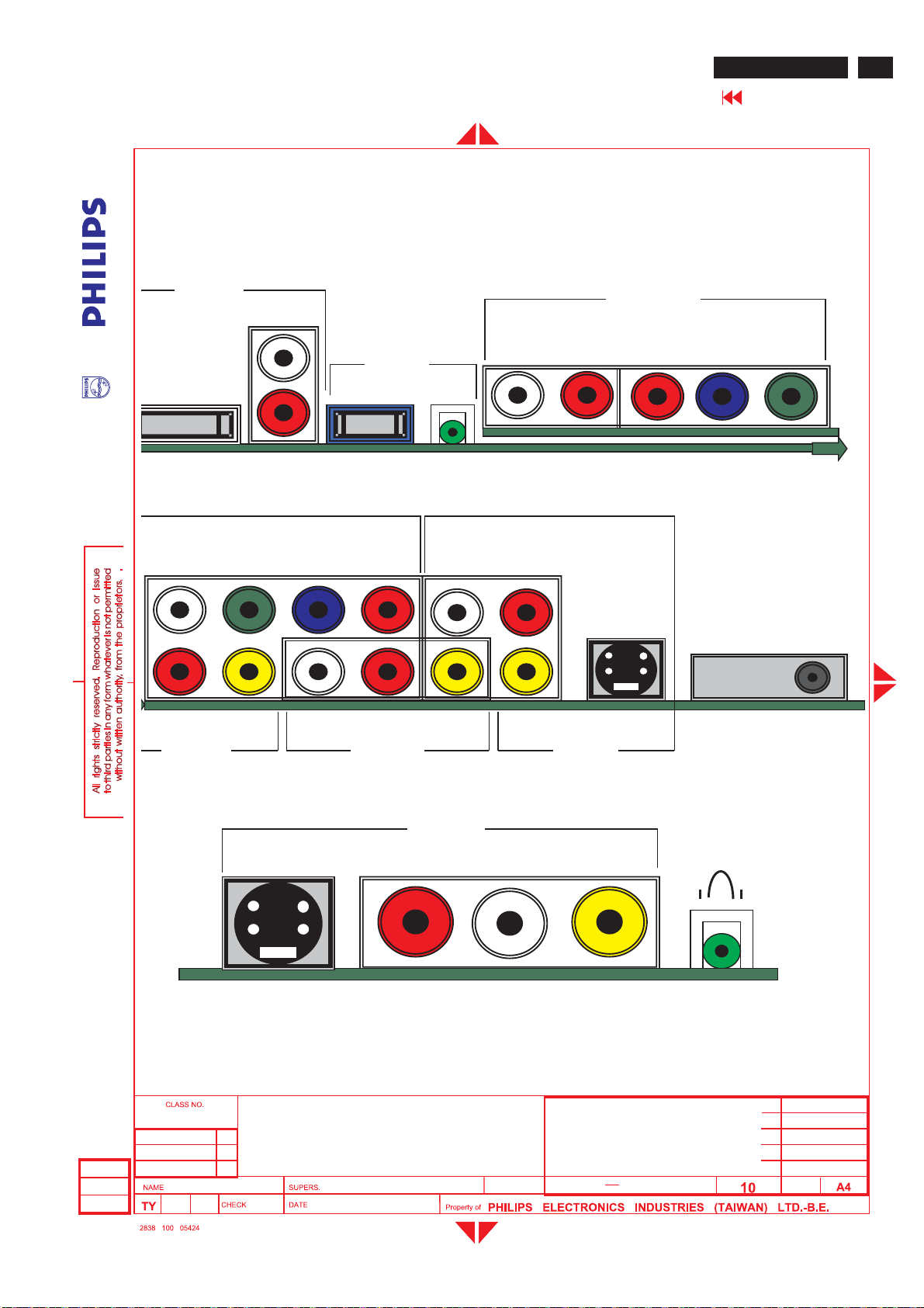
GENERAL PRODUCT SPECIFICATION(Continued)
4. HDIN:HDTV inputwith YPbPrformatand audio R/L(RCA jack).
5. AV IN3: Componentvideo YPbPrand composite video(Video 3) share with same audio R/L.
6. AV OUT: Composite video output (CVBS) and audio R/L(RCA jack).
7. AV IN1: Video1 (CVBS) and
8. AV IN2: Video2 (CVBS) and S-Video 2 share with same audio R/L.
9. Headphoneout
Location:
DVIIN
AUDIO
S-Video 1 share with same audio R/L.
AUDIO COMP VIDEO
26MF605W/17
HDIN
87
Go to cover page
L
LR Pr PbY
PC IN
DVI
R
VGA AUDIO
(HDCP
)
COMP VIDEO AUDIO
Y Pb Pr LR
L
TUNER
R
Video 3 LRVideo Video1 S-Video1
AV IN 3 AV OUT AV IN 1
2004-12-20
Peter Hsieh
AV IN 2
S-Video2 RLVideo2
26" Wide LCD Monitor / TV
TYPE :26MF605W/17
BRAND :Magnavox
18
2004-12-20
8639 000 16053
590
8
HeadphoneJack
Page 88
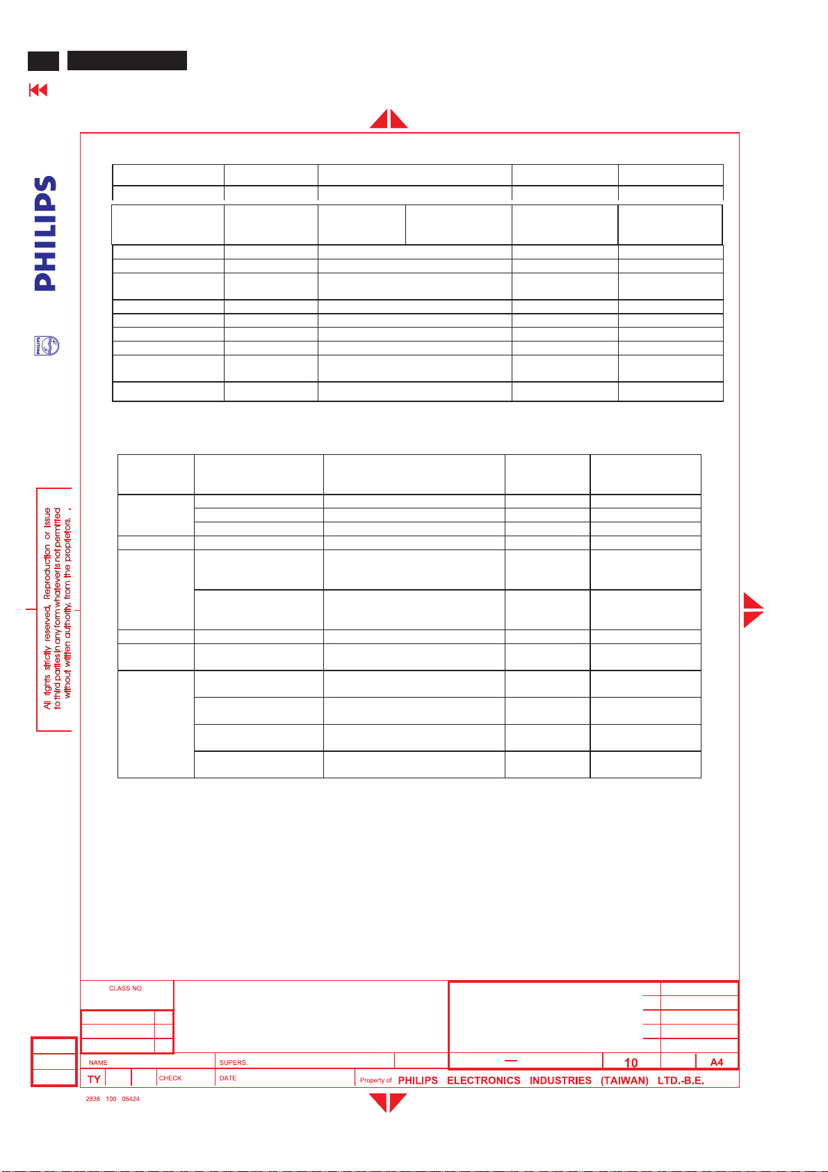
88
26MF605W/17
Go to cover page
Following table is the deviation of main TV system.
GENERAL PRODUCT SPECIFICATION(Continued)
Item W EUROPE America AP China
TV Color system PAL, SECAM NTSC PAL/NTSC PAL
Tuner
V system B/G, D/K, I, L M B/G , NTSC-M D/K
Sound decoder MSP3410G MSP3440G MSP3410G MSP3410G
CVBS, YC
Color system
Scaler MCU WE version NAFTA version AP version China version
Closed caption N Y N N
V-chip N Y N N
Teletext N N N N
Remote
controller(RC5)
Channel number 100 US Air 68, cable 125 100 100
Following table is the detail TV System list.
FQ1216ME5
Picture carrier
38.9MHz
Multi Multi Multi Multi
NAFTA version NAFTA version NAFTA version NAFTA version
FQ1236/F H-5
Picture carrier
45.75MHz
TSVN1-802FR3
Picture carrier
45.75MHz
FQ1216PN
Picture carrier
38.9MHz
FQ1256/I H-3
Picture carrier
38MHz
TV system Position of sound
M
N 4.5 BTSC-stereo SAP PAL Argentina
B/G
L 6.5/5.85 AM-Mono/NICAM SECAM-L France
I 6.0/6.552 FM-Mono/NICAM PAL Great Britain, Hong
D/K
3.3.2.1 TV special setting
carrier
(MHz)
4.5/4.724212 FM-Stereo (A2) NTSC Korea
4.5 FM-FM (EIA-J) NTSC Japan
4.5 BTSC-stereo SAP NTSC USA
5.5/5.7421875 FM-stereo (A2) PAL Germany, Austria,
5.5/5.85 FM-Mono/NICAM PAL Belgium, Spain,
6.5/6.2578125 FM-Stereo
6.5/6.7421875 FM-Stereo
6.5/5.7421875 FM-Stereo
6.5/5.85 FM-Mono/
Close Caption, V-chip (NAFTA Tuner, CVBS input source only)
Sound system Color system Country
Switzerland, Italy,
Netherlands.
Denmark, Finland,
Norway, Sweden.
Kong, Ireland.
SECAM-East Slovak. Rep.
(A2, D/K1)
PAL None
(A2, D/K2)
SECAM-East Poland
(A2, D/K3)
PAL China, Hungary
NICAM (D/K, NICAM)
- CC-1, CC-4 decoding and display
- TXT1, TXT4 Text mode
- No Extended Data Services (EDS)
- Support violence rating and checking
- Automatic CC-1 selection at user mute
2004-12-20
Peter Hsieh
26" Wide LCD Monitor / TV
TYPE : 26MF605W/17
BRAND : Magnavox
2004-12-20
18
8639 000 16053
590
9
Page 89
GENERAL PRODUCT SPECIFICATION(Continued)
3.3.3 Electriccharacteristics of I/O
3.3.3.1 PC Signal type
Analog Video : 0.7 Vp-p linear, positive polarity
Separate Sync. : TTL level, separate, positive or negative polarity
Audiosignal : Mini-jack audio input,
Level: Nominal :0.5Vrms.
Maximum:1.5Vrms.
Impedance > 10 k
Signal source : pattern generator format as attachment. (table 1 to 6 )
Reference generator: CHROMA 2200 or 2250
3.3.3.2 TV Signal type
RFsignal : Aerial input / 10mV(80dBuV)
Video signal : Video(RCACVBSinput) /1Vpp(300mV-sync, 700mV-video.)
S video input/1VppY-signal, 300mVpp C-signal
COMP Video(YPbPr input)/1
DVI : Digital interface with 4 channels TMDS signal
Audiosignal : Audio (1)R/L for AV IN1 (Video1 and S-video1).
Level: Nominal :0.5Vrms.
Maximum:1.5Vrms.
Impedance > 10 k
Audio (2)R/L for AV IN2 (Video2 and S-video2).
Level: Nominal :0.5Vrms.
Maximum:1.5Vrms.
Impedance > 10 k
Audio (3)R/L for AV IN3 (Video3 and Comp video).
Level: Nominal :0.5Vrms.
Maximum:1.5Vrms.
Impedance > 10 k
Audio (4)R/L for DVIIN.
Level: Nominal :0.5Vrms.
Maximum:1.5Vrms.
Impedance > 10 k
.
VppYsignal, 350mVpp Pb,Prsignal
.
.
.
.
26MF605W/17
Go to cover page
89
3.3.3.3 PVR output (CVBS output)
Video: CVBS output1Vpp/Impedance : 75
Audio: R/L output (from CVBS)
3.3.3.4 Headphoneoutput
Audio: R/L output -10mW at 32.
3.5mm stereo jack with switch
Impedance is between 8and 600.
3.4 Power inputconnection
Power cord length : 1.8 M
Power cord type : 3 leadspowercord with protective earth plug.
2004-12-20
Peter Hsieh
Level: Nominal :0.5Vrms.
Maximum:1.5Vrms.
Impedance < 1 k
.
26" Wide LCD Monitor / TV
TYPE :26MF605W/17
BRAND :Magnavox
2004-12-20
.
8639 000 16053
18
590
10
Page 90
90
26MF605W/17
Go to cover page
GENERAL PRODUCT SPECIFICATION(Continued)
3.5 Power management
PC mode
The power consumption and the status indication of the set
with power management function are as follows:
STATUS Horizontal Vertical 120V
On Pulse Pulse Typical 70W Green
Stand-by No Pulse Pulse < 1 W < 1W Amber
Suspend Pulse No Pulse < 1 W < 1W Amber
Off NoPulse NoPulse <1W <1W Amber
Power switch off - - < 1 W < 1 W -
TV mode
The power consumption and the status indication of the set with power management function are as follows,
STATUS 120VAC230VACLED
On Typical 105W Green
Stand-by < 1 W < 1 W Amber
Power switch off < 1 W < 1 W -
In Monitor power saving mode
Which no H&V sync or absent either H-sync or V-sync input via VGA connector. The monitor will enter "Monitor saving
mode". The way to wake up or change source:
1. H-sync and V-sync have signal again.
2. Press "Source" key on remote control, change to video source directly.
In TV power saving mode
Which switched off by RC "Power" key, SLEEP TIMER function or no TV signal input for 30 minutes, the monitor will
enter "TV standby mode" and LED shows amber color. The way to wake up:
1. Press "Power" key on remote control to return original video source.
2. Press "Source" key on remote control, change to video source directly.
,
Power Spec
,
Power Spec
230V
AC
LED
AC
4.0 Visual characteristics
4.1 Test conditions
Unless otherwise specified, this specification is defined under the following conditions.
(1) Input signal: As defined in 3.3.1.5, 1280 x 768 x 60Hz non-interlaced mode (47.776kHz), signal sources must have 75
ohm output impedance.
(2) Luminance setting: controls to be set to 500 Nits (typical) with full screen 700mv white signal.
(3) Warm up: more than 30 minutes after power on with signal supplied.
(4) Ambient light: 400 ~ 600 lux.
(5) Ambient temperature: 25 ± 2 °C
4.2 PC Resolution
Resolution Frequency Pixel rate Sync Comment
1 640X480 31.469K/59.94Hz 25.175MHz (-/-) IBM VGA
2 800X600 35.156K/56.25Hz 36MHz (+/+) VESA
3 800X600 37.879K/60.317Hz 40MHz (+/+) VESA
4 1024X768 48.363K/60.004Hz 65MHz (-/-) VESA
5 1280X720 44.772K/59.855Hz 74.5MHz (-/+) CVT
6 1280X768 47.776K/59.87Hz 79.5MHz (-/+) CVT
26" Wide LCD Monitor / TV
TYPE : 26MF605W/17
2004-12-20
Peter Hsieh
BRAND : Magnavox
18
2004-12-20
8639 000 16053
590
11
Page 91
GENERAL PRODUCT SPECIFICATION(Continued)
4.3 Brightness
>400 nits at maximumcontrast and Brightness. (Atcenter of the screen,Fig. 1)
4.4 Image size
4.4.1 Actual display size 575.769mmx323.712mm
4.5 Brightness uniformity
Set contrastat100%and turn the brightness to Max. (Atoriginal color)
Apply the Fig1,itshould comply with the followingformula:
26MF605W/17
Go to cover page
91
Maximumluminance of five points (brightness)
¾¾¾¾
Minimumluminance of five points (brightness)
4.6 PC White color adjustment
Apply 1280x768@60Hz modesetsmartpicture to "Normal", Apply full white pattern,with brightness in 50 % position and
the contrast control at 50% position.
The 1931 CIE Chromaticity (color triangle)d
8500K CIE coordinates X = 0.289 ± 0.030
4.7 TVWhite color adjustment
Smart picture set to personal for TV RFsignal (80dBmv).
Use FLUKE 54200 pattern generator with full white pattern.
Use The 1931 CIE Chromaticity (color triangle)diagram (X, Y) coo
X=0.289+/-0.030, Y=0.304+/-0.030.
4.8 TVpicture centering
Use CVBS(PALand NTSC) inputwith cross hatch pattern to check the picture centeringand should be
Left (size)-Right (size) < ± 3mm.
Up (size)-Down(size) < ± 3mm.
¾¾¾¾¾¾¾¾¾¾¾¾¾¾¾¾ <1.3
iagram (X, Y) coordinateforthescreen center should be:
Y = 0.304 ± 0.030
rdinate for the screen center should be:
5.0 Mechani cal characteristics
5.1 Controls
2004-12-20
Peter Hsieh
Top Control :
- Upkey
- Down key
-Menu key
- Right key
- Left key
Front-RC sensor
- DC power switch
Rear I/O :
- AC inlet
- DVI(Support HDCP) input
- L/R audio inputforDVI
- PC D-sub
-Mini jack PC audio input
- L/R audio inputforHD
-YPbPrvideo inputf
26" Wide LCD Monitor / TV
TYPE :26MF605W/17
BRAND :Magnavox
2004-12-20
18
orHD
8639 000 16053
590
12
Page 92
92
26MF605W/17
Go to cover page
GENERAL PRODUCT SPECIFICATION(Continued)
- Tuner RF input
- S-Video1 input
- Composite video input (VIDEO 1)
- L/R audio input (S-video1 and Video1 share with same audio)
- Composite video output
- L/R audio output
- YPbPr video input for component
- Composite video input (Video 3)
- L/R audio input (Component and Video 3 share with same audio)
Side I/O :
5.2 Unit dimension / Weight
Set dimension (incl. pedestal): 820 mm W x 213 mm H x 480 mm D
Net weight : 11.5 Kg
5.3 Tilt base
Tilt angle : 0 to 20 degree
5.4 Transportation packages
5.4.1 Shipping dimension/Weight
5.4.2 Block unit / Palletization (Sea shipment)
Carton dimension : 927 mm W x 585 mm H x 347 mm D
Gross weight : 14 Kg
Container
40 3 3 9
layers/block sets/layer sets/block unit
6.0 Environmental characteristics
The following sections define the interference and susceptibility condition limits that might occur between external
environment and the display device.
6.1 Susceptibility of display to external environment
- Headphone jack output
- S-Video 2 input
- Composite video input (Video 2)
- L/R Audio input (S-video 2 and Video 2 share with same audio)
2004-12-20
Peter Hsieh
Operating
- Temperature : 0 to 40
- Humidity : 10 to 95%(non - condensing)
- Altitude : 0 to 12000 feet
- Air pressure : 600 to 1100 mBAR
- (guaranteed optical performance): 5 to 35
- (guaranteed functional performance): 5 to 40
Storage
- Temperature : -20 to 50
- Humidity : 10 to 95% (non - condensing )
- Air pressure : 600 to 1100 mBAR
Note: recommend at 0 to 35°C, Humidity less than 60 %
Shipping
- Temperature :( -20 to 50
- Humidity : 10 to 95% (non - condensing )
- Altitude : 0 to 40000 feet ( non operating )
- Air pressure : 600 to 1100 mBAR
26" Wide LCD Monitor / TV
TYPE : 26MF605W/17
BRAND : Magnavox
2004-12-20
)
8639 000 16053
18
590
13
Page 93
GENERAL PRODUCT SPECIFICATION(Continued)
6.2 Transportation tests
StandardUAN-D1534/01
Height 61 cm
1 Corner-3Edag - 6Face
Total 10 Drops
Drop Sequence
Test
Electrical function ok
Test Mechanical function ok
Result Noserious damage on set appearance
(room temp./-10 ,humidity 70 %)
Sequence --- PACKAGING
Vibration 73Grms Truck spectruh 5~500Hz,
30min for each axis, 3AXES
Test Test Electrical function ok
Result Mechanical function ok
Noserious damage on set appearance
6.3 Display disturbances from external environment
26MF605W/17
Go to cover page
93
AccordingtoIEC 801-2 for ESD disturbances
7.0 Reliability
7.1 MeanTime Between Failures
System MTBF (ExcludingtheLCD panel and CCFL) : 50,000 hrs
CCFL MTBF : 50,000 hrs
8.0 Quality assurance requirements
8.1 Acceptance test
AccordingtoMIL-STD-105DControl II level
AQL :0.65(major)
(Please also refer to annual quality agreement)
9.0 Serviceability
The serviceability of thismonitor should fulfill the requirements which are prescribedinUAW-0346 and must be
checked with the check list UAT-0361.
2.5 (minor)
2004-12-20
Peter Hsieh
26" Wide LCD Monitor / TV
TYPE :26MF605W/17
BRAND :Magnavox
2004-12-20
18
8639 000 16053
590
14
Page 94
94
26MF605W/17
Go to cover page
Fig 1: Brightness and Uniformity measure points
GENERAL PRODUCT SPECIFICATION(Continued)
V
Table 1.
NAFTA TV Channels
US- Air broadcast channel
Broadcast
Channel
2 55.25 59.75 54-60
3 61.25 65.75 60-66
4 67.25 71.75 66-72
5 77.25 81.75 76-82
6 83.25 87.75 82-88
7 175.25 179.75 174-180
8 181.25 185.75 180-186
9 187.25 191.75 186-192
10 193.25 197.75 192-198
11 199.25 203.75 198-204
12 205.25 209.75 204-210
13 211.25 215.75 210-216
14 471.25 475.75 470-476
15 477.25 481.75 476-482
16 483.25 487.75 482-488
17 489.25 493.75 488-494
18 495.25 499.75 494-500
19 501.25 505.75 500-506
20 507.25 511.75 506-512
21 513.25 517.75 512-518
22 519.25 523.75 518-524
23 525.25 529.75 524-530
24 531.25 535.75 530-536
25 537.25 541.75 536-542
26 543.25 547.75 542-548
27 549.25 553.75 548-554
28 555.25 559.75 554-560
29 561.25 565.75 560-566
30 567.25 571.75 566-572
31 573.25 577.75 572-578
H/10
H/2
b
a
1
5
3
a
b
Video Carrier (MHz) Audio Carrier
H
(MHz)
9H
/10
2
4
b
a
V/
10
V/2
9V/
10
a
b
Range
(MHz)
2004-12-20
Peter Hsieh
26" Wide LCD Monitor / TV
TYPE : 26MF605W/17
BRAND : Magnavox
2004-12-20
18
8639 000 16053
590
15
Page 95
GENERAL PRODUCT SPECIFICATION(Continued)
32 579.25 583.75 578-584
33 585.25 589.75 584-590
34 591.25 595.75 590-596
35 597.25 601.75 596-602
36 603.25 607.75 602-608
37 609.25 613.75 608-614
38 615.25 619.75 614-620
39 621.25 625.75 620-626
40 627.25 631.75 626-632
41 633.25 637.75 632-638
42 639.25 643.75 638-644
43 645.25 649.75 644-650
44 651.25 655.75 650-656
45 657.25 661.75 656-662
46 663.25 667.75 662-668
47 669.25 673.75 668-674
48 675.25 679.75 674-680
49 681.25 685.75 680-686
50 687.25 691.75 686-692
51 673.25 697.75 692-698
52 699.25 703.75 698-704
53 705.25 709.75 704-710
54 711.25 715.75 710-716
55 717.25 721.75 716-722
56 723.25 727.75 722-728
57 729.25 733.75 728-734
58 735.25 739.75 734-740
59 741.25 745.75 740-746
60 747.25 751.75 746-752
61 753.25 757.75 752-758
62 759.25 763.75 758-764
63 765.25 769.75 764-770
64 771.25 775.75 770-776
65 777.25 781.75 776-782
66 783.25 787.75 782-788
67 789.25 793.75 788-794
68 795.25 799.75 794-800
69 801.25 805.75 800-806
26MF605W/17
Go to cover page
95
US-Cable channel
Cable
Channel
2004-12-20
Peter Hsieh
Video carrier
MHz
2 55.25 59.75 54-60
3 61.25 65.75 60-66
4 67.25 71.75 66-72
1 73.25 77.75 72-78
5 79.25 83.75 76-82
6 85.25 89.75 82-88
95 91.25 95.75 90-96
96 97.25 101.75 96-102
97 103.25 107.75 102-108
98 109.25 113.75 108-114
99 115.25 119.75 114-120
14 121.25 125.75 120-126
15 127.25 131.75 126-132
16 133.25 137.75 132-138
17 139.25 143.75 138-144
18 145.25 149.75 144-150
Audiocarrier
MHz
Range
MHz
26" Wide LCD Monitor / TV
TYPE :26MF605W/17
BRAND :Magnavox
18
2004-12-20
8639 000 16053
590
16
Page 96
96
26MF605W/17
Go to cover page
GENERAL PRODUCT SPECIFICATION(Continued)
19 151.25 155.75 150-156
20 157.25 161.75 156-162
21 163.25 167.75 162-168
22 169.25 173.75 168-174
7 175.25 179.75 174-180
8 181.25 185.75 180-186
9 187.25 191.75 186-192
10 193.25 197.75 192-198
11 199.25 203.75 198-204
12 205.25 209.75 204-210
13 211.25 215.75 210-216
23 217.25 221.75 216-222
24 223.25 227.75 222-228
25 229.25 233.75 228-234
26 235.25 239.75 234-240
27 241.25 245.75 240-246
28 247.25 251.75 246-252
29 253.25 257.75 252-258
30 259.25 263.75 258-264
31 265.25 269.75 264-270
32 271.25 275.75 270-276
33 277.25 281.75 276-282
34 283.25 287.75 282-288
35 289.25 293.75 288-294
36 295.25 299.75 294-300
37 301.25 305.75 300-306
38 307.25 311.75 306-312
39 313.25 317.75 312-318
40 319.25 323.75 318-324
41 325.25 329.75 324-330
42 331.25 335.75 330-336
43 337.25 341.75 336-342
44 343.25 347.75 342-348
45 349.25 353.75 348-354
46 355.25 359.75 354-360
47 361.25 365.75 360-366
48 367.25 371.75 366-372
49 373.25 377.75 372-378
50 379.25 383.75 378-384
51 385.25 389.75 384-390
52 391.25 395.75 390-396
53 397.25 401.75 396-402
54 403.25 407.75 402-408
55 409.25 413.75 408-414
56 415.25 419.75 414-420
57 421.25 425.75 420-426
58 427.25 431.75 426-432
59 433.25 437.75 432-438
60 439.25 443.75 438-444
61 445.25 449.75 444-450
62 451.25 455.75 450-456
63 457.25 461.75 456-462
64 463.25 467.75 462-468
65 469.25 473.75 468-474
66 475.25 479.25 474-480
67 481.25 485.75 480-486
68 487.25 491.75 486-492
69 493.25 497.75 492-498
70 499.25 503.75 498-504
2004-12-20
Peter Hsieh
26" Wide LCD Monitor / TV
TYPE : 26MF605W/17
BRAND : Magnavox
2004-12-20
18
8639 000 16053
590
17
Page 97
GENERAL PRODUCT SPECIFICATION(Continued)
71 505.25 509.75 504-510
72 511.25 515.75 510-516
73 517.25 521.75 516-522
74 523.25 527.75 522-528
75 529.25 533.75 528-534
76 535.25 539.75 534-540
77 541.25 545.75 540-546
78 547.25 551.75 546-552
79 553.25 557.75 552-558
80 559.25 563.75 558-564
81 565.25 569.75 564-570
82 571.25 575.75 570-576
83 577.25 581.75 576-582
84 583.25 587.75 582-588
85 589.25 593.75 588-594
86 595.25 599.75 594-600
87 601.25 605.75 600-606
88 607.25 611.75 606-612
89 613.25 617.75 612-618
90 619.25 623.75 618-624
91 625.25 629.75 624-630
92 631.25 635.75 630-636
93 637.25 641.75 636-642
94 643.25 647.75 642-648
100 649.25 653.75 648-654
101 655.25 659.75 654-660
102 661.25 665.75 660-666
103 667.25 671.75 666-672
104 673.25 677.75 672-678
105 679.25 683.75 678-684
106 685.25 689.75 684-690
107 691.25 695.75 690-696
108 697.25 701.75 696-702
109 703.25 707.75 702-708
110 709.25 713.75 708-714
111 715.25 719.75 714-720
112 721.25 725.75 720-726
113 727.25 731.75 726-732
114 733.25 737.75 732-738
115 739.25 743.75 738-744
116 745.25 749.75 744-750
117 751.25 755.75 750-756
118 757.25 761.75 756-762
119 763.25 767.75 762-768
120 769.25 773.75 768-774
121 775.25 779.75 774-780
122 781.25 785.75 780-786
123 787.25 791.75 786-792
124 793.25 797.75 792-798
125 799.25 803.75 798-804
26MF605W/17
Go to cover page
97
2004-12-20
Peter Hsieh
26" Wide LCD Monitor / TV
TYPE :26MF605W/17
BRAND :Magnavox
2004-12-20
18
8639 000 16053
590
18
Page 98

98
26MF605W/17
Go to cover page
DDC Data
THE DISPLAY DATA CHANNEL (DDC_2B) CONTENT INCLUDING:
(FOR 26MF605/17 ANALOG FOR LPLPANEL)
**********************************************************************
EDID log file
**********************************************************************
Vendor/Product Identification
ID Manufacturer Name : PHL
ID Product Code : 0000 (HEX.)
ID Serial Number : 79 (HEX.)
Week of Manufacture : 4
Year of Manufacture : 2005
EDID Version, Revision
Version : 1
Revision : 3
Basic Display Parameters/Features
Video Input Definition : Analog Video Input
0.700V/0.000V (0.70Vpp)
without Blank-to-Black Setup
Separate Sync
Composite Sync
without Sync on Green
no Serration required
Maximum H Image Size : 58
Maximum V Image Size : 33
Display Transfer Characteristic : 2.2
(gamma)
Feature Support (DPMS) : Standby
Suspend
no Active Off
Display Type : RGB color display
Standard Default Color Space : Primary color space
Preferred Timing Mode : Detailed timing block 1
Color Characteristics
Red X coordinate : 0.64
Red Y coordinate : 0.34
Green X coordinate : 0.282
Green Y coordinate : 0.607
Blue X coordinate : 0.145
Blue Y coordinate : 0.066
White X coordinate : 0.275
White Y coordinate : 0.279
Established Timings
Established Timings I : 640 x 480 @60Hz (IBM,VGA)
800 x 600 @56Hz (VESA)
800 x 600 @60Hz (VESA)
H Image Size (mm) : 372
V Image Size (mm) : 223
H Border (pixels) : 0
V Border (lines) : 0
Flags : Non-interlaced
: Normal Display, No stereo
: Digital Separate sync.
: Positive Vertical Sync.
: Negative Horizontal Sync.
Monitor Descriptor #2
Serial Number : 12345
Monitor Descriptor #3
Monitor Name : 26MF605W/17
Monitor Descriptor #4
Monitor Range Limits
Min. Vt rate Hz : 56
Max. Vt rate Hz : 63
Min. Horiz. rate kHz : 30
Max. Horiz. rate kHz : 50
Max. Supported Pixel : 80
No secondary GTF timing formula supported.
Extension Flag : 0
Check sum : 48 (HEX.)
**********************************************************************
EDID data (128 bytes)
**********************************************************************
0: 00 1: ff 2: ff 3: ff 4: ff 5: ff 6: ff 7: 00
8: 41 9: 0c 10: 00 11: 00 12: 79 13: 00 14: 00 15: 00
16: 04 17: 0f 18: 01 19: 03 20: 6c 21: 3a 22: 21 23: 78
24: ce 25: c6 26: 0a 27: a3 28: 57 29: 48 30: 9b 31: 25
32: 11 33: 46 34: 47 35: 23 36: 08 37: 00 38: 81 39: c0
40: 01 41: 01 42: 01 43: 01 44: 01 45: 01 46: 01 47: 01
48: 01 49: 01 50: 01 51: 01 52: 01 53: 01 54: 0e 55: 1f
56: 00 57: 80 58: 51 59: 00 60: 1e 61: 30 62: 40 63: 80
64: 37 65: 00 66: 74 67: df 68: 10 69: 00 70: 00 71: 1c
72: 00 73: 00 74: 00 75: ff 76: 00 77: 31 78: 32 79: 33
80: 34 81: 35 82: 0a 83: 20 84: 20 85: 20 86: 20 87: 20
88: 20 89: 20 90: 00 91: 00 92: 00 93: fc 94: 00 95: 32
96: 36 97: 4d 98: 46 99: 36 100: 30 101: 35 102: 57 103: 2f
104: 31 105: 37 106: 0a 107: 20 108: 00 109: 00 110: 00 111: fd
112: 00 113: 38 114: 3f 115: 1e 116: 32 117: 08 118: 00 119: 0a
120: 20 121: 20 122: 20 123: 20 124: 20 125: 20 126: 00 127: 48
Established Timings II : 1024 x 768 @60Hz (VESA)
Manufacturer's timings :
Standard Timing Identification #1
Horizontal active pixels : 1280
Aspect Ratio : 16:9
Refresh Rate : 60
Detailed Timing #1
Pixel Clock (MHz) : 79.5
H Active (pixels) : 1280
H Blanking (pixels) : 384
V Active (lines) : 768
V Blanking (lines) : 30
H Sync Offset (F Porch) (pixels): 64
H Sync Pulse Width (pixels) : 128
V Sync Offset (F Porch) (lines) : 3
V Sync Pulse Width (lines) : 7
Page 99

DDC Data
26MF605W/17
Go to cover page
99
(FOR 26MF605W/17 DIGITAL FOR LPL PANEL)
**********************************************************************
EDID log file
**********************************************************************
Vendor/Product Identification
ID Manufacturer Name : PHL
ID Product Code : 0000 (HEX.)
ID Serial Number : 79 (HEX.)
Week of Manufacture : 4
Year of Manufacture : 2005
EDID Version, Revision
Version : 1
Revision : 3
Basic Display Parameters/Features
Video Input Definition : Digital Video Input
Maximum H Image Size : 58
Maximum V Image Size : 33
Display Transfer Characteristic : 2.2
(gamma)
Feature Support (DPMS) : no Standby
no Suspend
no Active Off
Display Type : RGB color display
Standard Default Color Space: Primary color space
Color Characteristics
Red X coordinate : 0.64
Red Y coordinate : 0.34
Green X coordinate : 0.282
Green Y coordinate : 0.607
Blue X coordinate : 0.145
Blue Y coordinate : 0.066
White X coordinate : 0.275
White Y coordinate : 0.279
Established Timings
Established Timings I : 640 x 480 @60Hz (IBM,VGA)
Established Timings II :
Manufacturer's timings :
Standard Timing Identification : Unused
Detailed Timing #1
Pixel Clock (MHz) : 74.25
H Active (pixels) : 1920
H Blanking (pixels) : 280
V Active (lines) : 540
V Blanking (lines) : 22
H Sync Offset (F Porch) (pixels): 88
H Sync Pulse Width (pixels) : 44
V Sync Offset (F Porch) (lines): 2
V Sync Pulse Width (lines) : 5
H Image Size (mm) : 576
V Image Size (mm) : 324
H Border (pixels) : 0
V Border (lines) : 0
Flags : Interlaced
: Normal Display, No stereo
: Digital Separate sync.
: Positive Vertical Sync.
: Positive Horizontal Sync.
H Active (pixels) : 720
H Blanking (pixels) : 138
V Active (lines) : 480
V Blanking (lines) : 45
H Sync Offset (F Porch) (pixels): 16
H Sync Pulse Width (pixels) : 62
V Sync Offset (F Porch) (lines) : 9
V Sync Pulse Width (lines) : 6
H Image Size (mm) : 576
V Image Size (mm) : 324
H Border (pixels) : 0
V Border (lines) : 0
Flags : Non-interlaced
: Normal Display, No stereo
: Digital Separate sync.
: Negative Vertical Sync.
: Negative Horizontal Sync.
Monitor Descriptor #3
Monitor Name : 26MF605W/17
Monitor Descriptor #4
Monitor Range Limits
Min. Vt rate Hz : 47
Max. Vt rate Hz : 61
Min. Horiz. rate kHz : 30
Max. Horiz. rate kHz : 47
Max. Supported Pixel : 80
No secondary GTF timing formula supported.
Extension Flag : 0
Check sum : C5 (HEX.)
**********************************************************************
EDID data (128 bytes)
**********************************************************************
0: 00 1: ff 2: ff 3: ff 4: ff 5: ff 6: ff 7: 00
8: 41 9: 0c 10: 00 11: 00 12: 79 13: 00 14: 00 15: 00
16: 04 17: 0f 18: 01 19: 03 20: 80 21: 3a 22: 21 23: 78
24: 0c 25: c6 26: 0a 27: a3 28: 57 29: 48 30: 9b 31: 25
32: 11 33: 46 34: 47 35: 20 36: 00 37: 00 38: 01 39: 01
40: 01 41: 01 42: 01 43: 01 44: 01 45: 01 46: 01 47: 01
48: 01 49: 01 50: 01 51: 01 52: 01 53: 01 54: 01 55: 1d
56: 80 57: 18 58: 71 59: 1c 60: 16 61: 20 62: 58 63: 2c
64: 25 65: 00 66: 40 67: 44 68: 21 69: 00 70: 00 71: 9e
72: 8c 73: 0a 74: d0 75: 8a 76: 20 77: e0 78: 2d 79: 10
80: 10 81: 3e 82: 96 83: 00 84: 40 85: 44 86: 21 87: 00
88: 00 89: 18 90: 00 91: 00 92: 00 93: fc 94: 00 95: 32
96: 36 97: 4d 98: 46 99: 36 100: 30 101: 35 102: 57 103: 2f
104: 31 105: 37 106: 0a 107: 20 108: 00 109: 00 110: 00 111: fd
112: 00 113: 2f 114: 3d 115: 1e 116: 2f 117: 08 118: 00 119: 0a
120: 20 121: 20 122: 20 123: 20 124: 20 125: 20 126: 00 127: c5
Detailed Timing #2
Pixel Clock (Mhz) : 27
Page 100

100
26MF605W/17
Go to cover page
DDC Data
THE DISPLAY DATA CHANNEL (DDC_2B) CONTENT INCLUDING:
(FOR 32MF605/17 ANALOG FOR LPLPANEL)
**********************************************************************
EDID log file for LPLPanel
**********************************************************************
Vendor/Product Identification
ID Manufacturer Name : PHL
ID Product Code : 0000 (HEX.)
ID Serial Number : 79 (HEX.)
Week of Manufacture : 4
Year of Manufacture : 2005
EDID Version, Revision
Version : 1
Revision : 3
Basic Display Parameters/Features
Video Input Definition : Analog Video Input
0.700V/0.000V (0.70Vpp)
without Blank-to-Black Setup
Separate Sync
Composite Sync
without Sync on Green
no Serration required
Maximum H Image Size : 69
Maximum V Image Size : 39
Display Transfer Characteristic : 2.2
(gamma)
V Sync Offset (F Porch) (lines) : 3
V Sync Pulse Width (lines) : 7
H Image Size (mm) : 697
V Image Size (mm) : 392
H Border (pixels) : 0
V Border (lines) : 0
Flags : Non-interlaced
: Normal Display, No stereo
: Digital Separate sync.
: Positive Vertical Sync.
: Negative Horizontal Sync.
Monitor Descriptor #2
Serial Number : 12345
Monitor Descriptor #3
Monitor Name : 32MF605W/17
Monitor Descriptor #4
Monitor Range Limits
Min. Vt rate Hz : 56
Max. Vt rate Hz : 63
Min. Horiz. rate kHz : 30
Max. Horiz. rate kHz : 50
Max. Supported Pixel : 80
No secondary GTF timing formula supported.
Extension Flag : 0
Check sum : DA (HEX.)
Feature Support (DPMS) : Standby
Suspend
no Active Off
Display Type : RGB color display
Standard Default Color Space : Primary color space
Preferred Timing Mode : Detailed timing block 1
Color Characteristics
Red X coordinate : 0.64
Red Y coordinate : 0.343
Green X coordinate : 0.28
Green Y coordinate : 0.605
Blue X coordinate : 0.145
Blue Y coordinate : 0.065
White X coordinate : 0.285
White Y coordinate : 0.293
Established Timings
Established Timings I : 640 x 480 @60Hz (IBM,VGA)
800 x 600 @56Hz (VESA)
800 x 600 @60Hz (VESA)
Established Timings II : 1024 x 768 @60Hz (VESA)
Manufacturer's timings :
Standard Timing Identification #1
Horizontal active pixels : 1280
Aspect Ratio : 16:9
Refresh Rate : 60
**********************************************************************
EDID data (128 bytes) for LPL Panel
**********************************************************************
0: 00 1: ff 2: ff 3: ff 4: ff 5: ff 6: ff 7: 00
8: 41 9: 0c 10: 00 11: 00 12: 79 13: 00 14: 00 15: 00
16: 04 17: 0f 18: 01 19: 03 20: 6c 21: 45 22: 27 23: 78
24: ce 25: fc 26: 30 27: a3 28: 57 29: 47 30: 9b 31: 25
32: 10 33: 49 34: 4b 35: 23 36: 08 37: 00 38: 81 39: c0
40: 01 41: 01 42: 01 43: 01 44: 01 45: 01 46: 01 47: 01
48: 01 49: 01 50: 01 51: 01 52: 01 53: 01 54: 0e 55: 1f
56: 00 57: 80 58: 51 59: 00 60: 1e 61: 30 62: 40 63: 80
64: 37 65: 00 66: b9 67: 88 68: 21 69: 00 70: 00 71: 1c
72: 00 73: 00 74: 00 75: ff 76: 00 77: 31 78: 32 79: 33
80: 34 81: 35 82: 0a 83: 20 84: 20 85: 20 86: 20 87: 20
88: 20 89: 20 90: 00 91: 00 92: 00 93: fc 94: 00 95: 33
96: 32 97: 4d 98: 46 99: 36 100: 30 101: 35 102: 57 103: 2f
104: 31 105: 37 106: 0a 107: 20 108: 00 109: 00 110: 00 111: fd
112: 00 113: 38 114: 3f 115: 1e 116: 32 117: 08 118: 00 119: 0a
120: 20 121: 20 122: 20 123: 20 124: 20 125: 20 126: 00 127: da
Detailed Timing #1
Pixel Clock (MHz) : 79.5
H Active (pixels) : 1280
H Blanking (pixels) : 384
V Active (lines) : 768
V Blanking (lines) : 30
H Sync Offset (F Porch) (pixels) : 64
H Sync Pulse Width (pixels) : 128
 Loading...