

Page 1
1
CORRECTLY INCORRECTLY
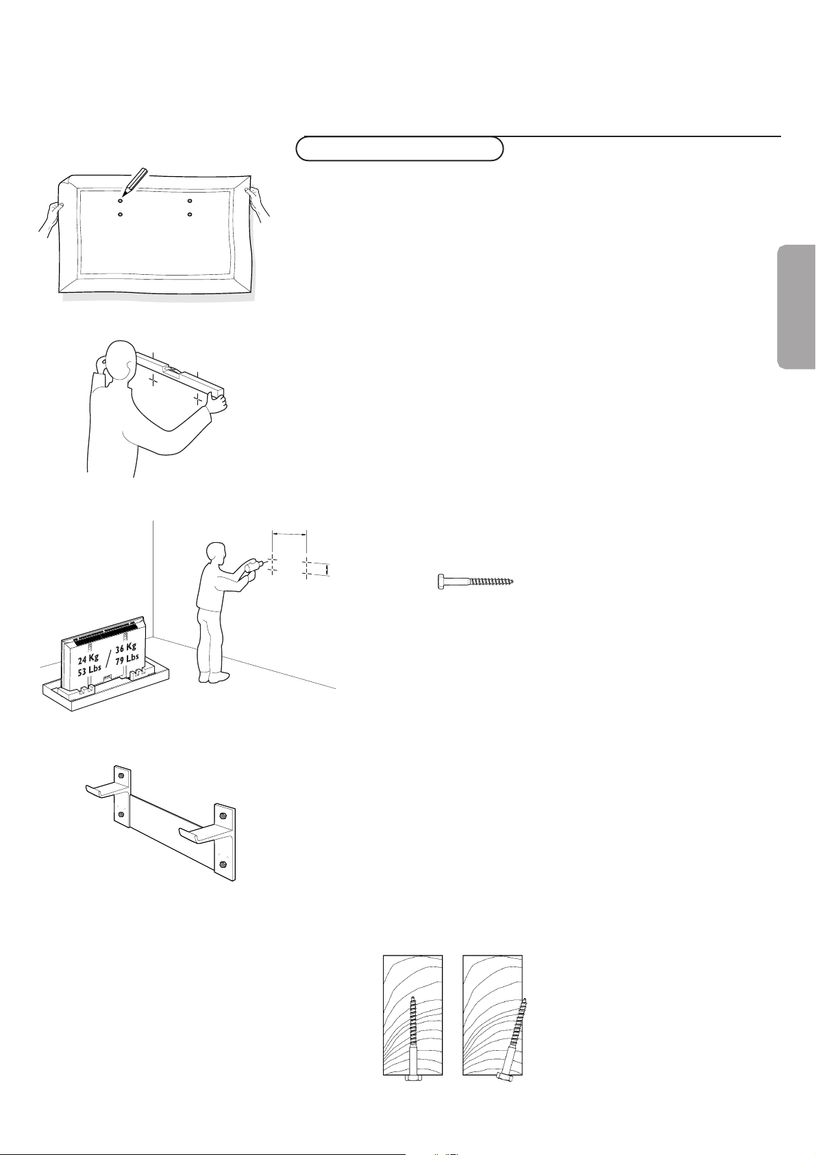
Note: the enclosed template can be used for general positioning only
(fig. 1).
Mounting to sheetrock wall
Note: Bracket can only be used with standard 16" spaced wood wall
studs.
Bracket must be positioned so that the bracket is fastened firmly to
studs at each end.
All required hardware is included.
Note: Because the Receiver Unit’s power cord is 6’, when determining the
Display Unit mounting location, the distance to the nearest AC power
outlet must be considered.
& Determine desired location to mount Display Unit.
Within this area, locate the two 16.54" spaced wall studs that must
be used as the Wall Bracket mounting location. (fig. 1 and 2)
é With the Wall Bracket held in place, ensure it is properly leveled.
Then, mark where the four holes must be drilled. (fig. 2)
Note: Use only the holes in Bracket.
“ Remove the Wall Bracket, and using a 13/64" wood drill bit, drill the
four holes. (fig. 3)
‘ Reposition the Wall Bracket, and with four lag bolts (fig. 4), secure
into place.Tighten with 13mm or 1/2" socket wrench. (fig. 5)
Note: Do not use plastic wall anchors with these lag bolts.
Note: Lag bolts must be fastened and centered securely into the stud.
Mounting Wall Bracket
fig. 1
English
fig. 2
fig. 3
fig. 5
420mm /16,54"
60,5mm /
2.38"
fig. 4
Page 2
2
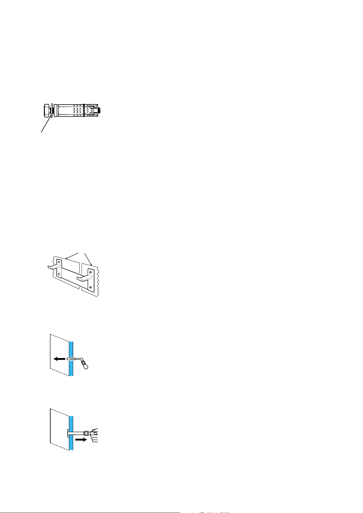
Mounting to concrete wall
&
Determine desired location to mount Display Unit. Use the enclosed
template for alignment purposes. (fig. 1)
é With the Wall Bracket held in place, ensure it is properly leveled.
Then, mark where the four holes must be drilled. (fig. 4)
“ Remove the Wall Bracket, and using a 5/8" masonry drill bit, drill the
four holes. (fig. 2)
‘ Insert a concrete anchor (with bolt) into each hole.
( Firmly tighten each bolt.Then, remove the bolts.
§ Reposition the Wall Bracket, and with the four bolts (and washers),
secure into place.
Mounting to concrete block wall
&
Determine desired location to mount the Display Unit.
Within this area, position the Wall Bracket so that the four end
mounting holes are located over the cavities of the concrete blocks
(refer to Figure 1)
é With the Wall Bracket held in place, ensure it is properly leveled.
Then, mark where the four holes are to be drilled.
Note: Use only the four outside or end holes in the Bracket.
“ Remove the Wall Bracket and reconfirm that the marks made in the
previous step are located in the cavities of the concrete blocks. Relocate the marks as required to ensure that they are in the cavities
of the concrete blocks.
‘ With a 1/2” masonry drill bit, drill the four holes.
( Hinge the plastic legs of the toggle bolt into the channel of the metal
end of the toggle bolt so it can fit into the 1/2” hole drilled in the
wall (refer to Figure 2).
§ Insert the toggle bolt into the hole in the wall and push it in until it
is in the cavity of the block.
è With the plastic pull ring of the toggle bolt, pull the metal end of the
toggle bolt firmly against the back of the cavity of the concrete block
(refer to Figure 3).
WASHER
Cavities In Block
Fig. 1
Fig. 2
Fig. 3
Page 3
3
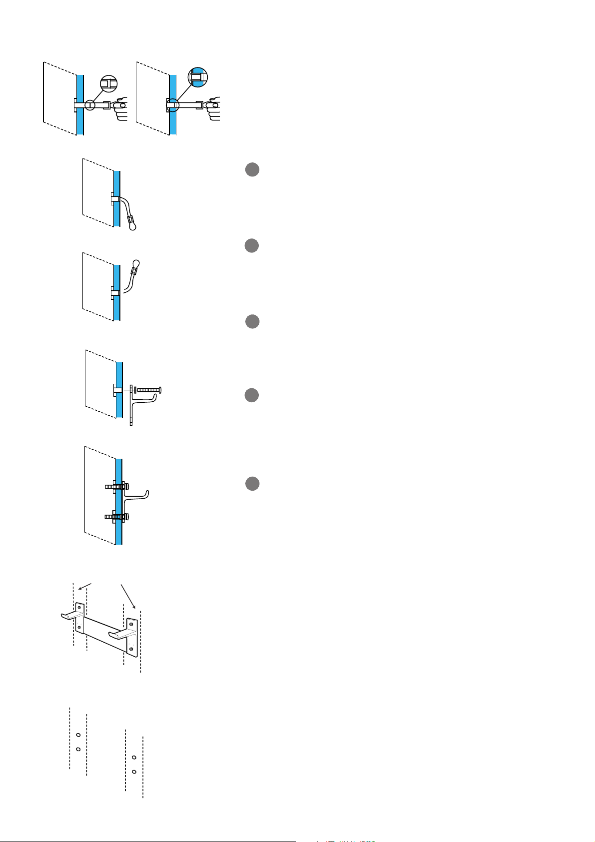
! While holding the plastic pull ring, slide the plastic retaining sleeve
towards the wall until it fits into the hole in the wall. This will hold
the toggle bolt in the wall while the Wall Bracket is mounted (refer
to Figure 4).
Push down on the lower plastic leg of the toggle bolt and break it off
flush with the wall (refer to Figure 5).
Push up on the upper plastic leg of the toggle bolt and break it off
flush with the wall (refer to Figure 6).
Install the remaining 3 toggle bolts in the remaining holes the same
way that the first one was installed.
Position the Wall Bracket in place and install the four 1/4-20 bolts,
including washers, in each of the outside corner holes. Do not
tighten completely (refer to Figure 7).
Confirm that the Wall Plate is level, then tighten the bolts securely
(refer to Figure 8).
Mounting to metal stud wall
&
Determine desired location to mount the Display Unit.
Within this area, locate the two 16.54” spaced metal wall studs that
must be used as the Wall Bracket mounting location.
é Locate the center of both wall studs at the height that the Wall
Bracket is to be mounted.
“ With the Wall Bracket held in place, ensure it is properly leveled.
Then, mark where the four holes are to be drilled.
Note: Use only the four outside or end holes in the Bracket
(refer to Figure 1).
‘ Remove the Wall Bracket and reconfirm that the marks made in the
previous step are located in the center of the metal wall studs. Relocate the marks as required to ensure that they are in the center of
the metal wall studs (refer to Figure 2).
9
10
11
12
13
Fig. 4
Fig. 5
Fig. 6
Fig. 7
Fig. 8
Metal Wall
Studs
Fig. 1
Holes Centered In
Metal Wall Studs
Fig. 2
Page 4
4
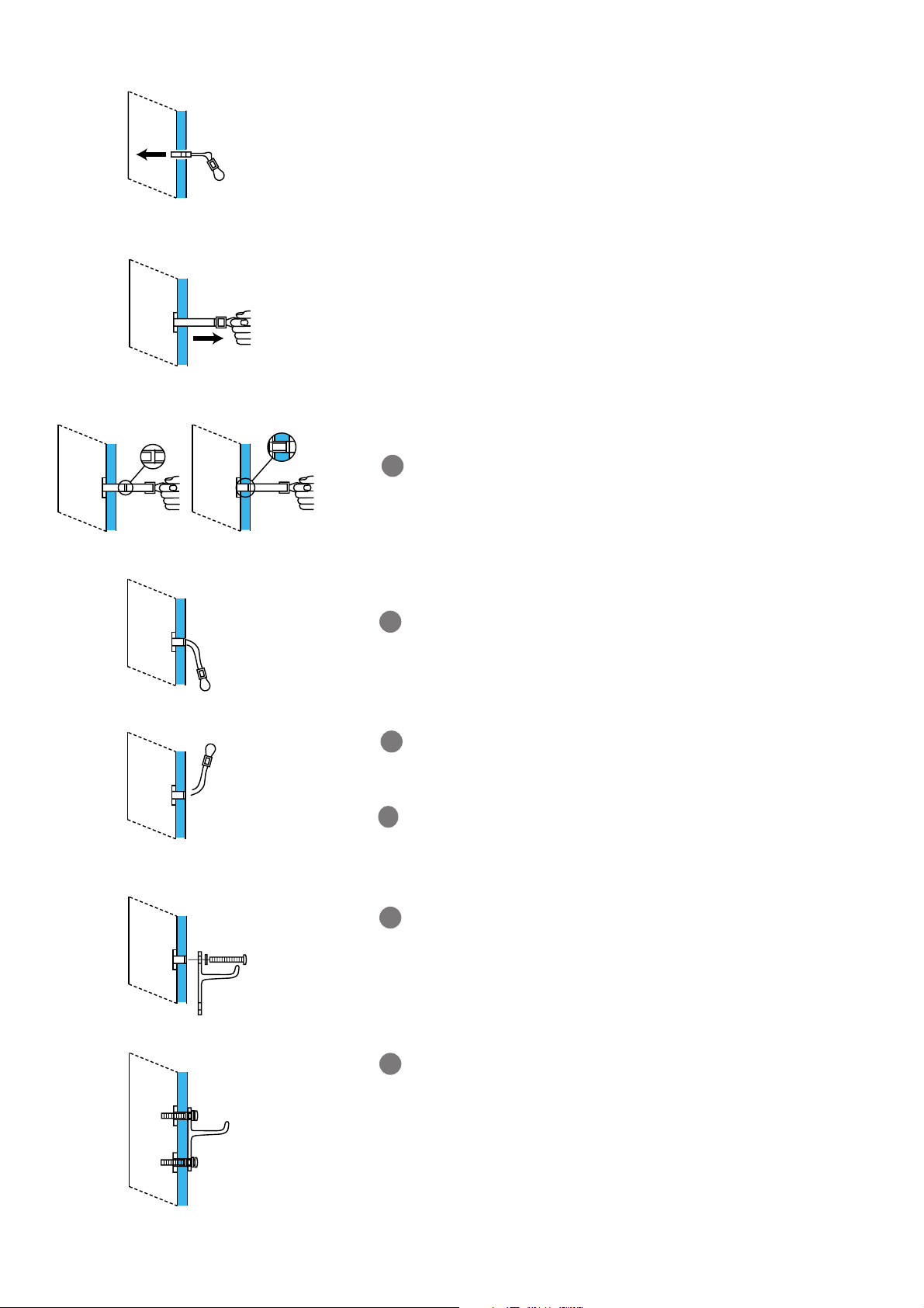
( With a 1/2” drill bit, drill the four holes. A smaller pilot hole may be
required if the 1/2” drill bit bends the metal stud instead of piercing
it.
§ Hinge the plastic legs of the toggle bolt into the channel of the metal
end of the toggle bolt so it can fit into the 1/2” hole drilled in the
wall (refer to Figure 3).
è Insert the toggle bolt into the hole in the wall and push it in past the
metal stud (refer to Figure 3).
! With the plastic pull ring of the toggle bolt, pull the metal end of the
toggle bolt firmly against the back of the metal stud (refer to Figure
4).
While holding the plastic pull ring, slide the plastic retaining sleeve
towards the wall until it fits into the hole in the wall. This will hold
the toggle bolt in the wall while the Wall Bracket is mounted (refer
to Figure 5).
Push down on the lower plastic leg of the toggle bolt and break it
off flush with the wall (refer to Figure 6).
Push up on the upper plastic leg of the toggle bolt and break it off
flush with the wall (refer to Figure 7).
Install the remaining 3 toggle bolts in the remaining holes the same
way that the first one was installed.
Position the Wall Bracket in place and install the four 1/4-20 bolts,
including washers, in each of the outside corner holes. Do not
tighten completely (refer to Figure 8).
Confirm that the Wall Plate is level, then tighten the bolts securely
(refer to Figure 9).
9
10
11
12
13
14
Fig. 3
Fig. 6
Fig. 7
Fig. 4
Fig. 5
Fig. 8
Fig. 9
Page 5
~ MAINS
RS232
DVI-D
Y/C S-VHS
L
R
L
R
AUDIO IN AUDIO IN
G/Y/Y
CVBS B/Pb/Cb
R/Pr/Cr V
H
AUDIO IN
R
VGA 1
VGA 2
RC-OUT
AV2 AV1 AV3
L
AUDIO IN
VGA 1VGA 2DVI-D
2
1
Page 6
1
Once your PHILIPS purchase is registered, you’re eligible to receive all the privileges of owning a
PHILIPS product. So complete and return the Warranty Registration Card enclosed with your
purchase at once, and take advantage of these important benefits.
Return your Warranty Registration card today to ensure
you receive all the
benefits
you’re entitled to.
For Customer Use
Enter below the Serial No., which is
located on the rear of the cabinet. Retain
this information for future reference.
Model No. __________________________
Serial No. __________________________
Congratulations on your purchase, and
welcome to the “family!”
Dear PHILIPS product owner:
Thank you for your confidence in PHILIPS.You’ve selected one of
the best-built, best-backed products available today.And we’ll do
everything in our power to keep you happy with your
purchase for many years to come.
As a member of the PHILIPS “family,” you’re entitled to
protection by one of the most comprehensive warranties and
outstanding service networks in the industry.
What’s more, your purchase guarantees you’ll receive all the
information and special offers for which you qualify, plus easy
access to accessories from our convenient home shopping
network.
And most importantly you can count on our uncompromising
commitment to your total satisfaction.
All of this is our way of saying welcome-and thanks for investing
in a PHILIPS product.
Sincerely,
Lawrence J. Blanford
President and Chief Executive Officer
P.S. Remember, to get the most from your PHILIPS
product, you must return your Warranty
Registration Card within 10 days. So please mail
it to us right now!
Know these
safety symbols
This “bolt of lightning” indicates
uninsulated material within your unit
may cause an electrical shock. For the
safety of everyone in your household, please
do not remove product
covering.
The “exclamation point” calls attention
to features for which you should read
the enclosed literature closely to
prevent operating and maintenance
problems.
WARNING: TO PREVENT FIRE OR
SHOCK HAZARD, DO NOT EXPOSE THIS
EQUIPMENT TO RAIN OR MOISTURE.
CAUTION: To prevent electric shock,
match wide blade of plug to wide slot, fully
insert.
ATTENTION: Pour éviter les choc
électriques, introduire la lame la plus large de
la fiche dans la borne correspondante de la
prise et pousser jusqu’au fond.
CAUTION
RISK OF ELECTRIC SHOCK
DO NOT OPEN
CAUTION: TO REDUCE THE RISK OF ELECTRIC SHOCK, DO NOT
REMOVE COVER (OR BACK). NO USER-SERVICEABLE PARTS
INSIDE. REFER SERVICING TO QUALIFIED SERVICE PERSONNEL.
R
E
G
I
S
T
R
A
T
I
O
N
N
E
E
D
E
D
W
I
T
H
I
N
1
0
D
A
Y
S
Hurry!
Warranty
Verification
Registering your product within
10 days confirms your right to
maximum protection under the
terms and conditions of your
PHILIPS warranty.
Owner
Confirmation
Your completed Warranty
Registration Card serves as
verification of ownership in the
event of product theft or loss.
Model
Registration
Returning your Warranty Registration
Card right away guarantees you’ll
receive all the information and special
offers which you qualify for as the
owner of your model.
Visit our World Wide Web Site at http://www.philips.com
t
s
Page 7

2
1. Read these instructions.
2. Keep these instructions.
3. Heed all warnings.
4. Follow all instructions.
5. Do not use this apparatus near water.
6. Clean only with a dry cloth.
7. Do not block any of the ventilation openings. Install in
accordance with the manufacturers instructions.
8. Do not install near any heat sources such as radiators, heat
registers, stoves, or other apparatus (including amplifiers) that
produce heat.
9. Do not defeat the safety purpose of the polarized or groundingtype plug. A polarized plug has two blades with one wider than
the other. A grounding type plug has two blades and third
grounding prong.The wide blade or third prong are provided for
your safety.When the provided plug does not fit into your
outlet, consult an electrician for replacement of the obsolete
outlet.
10. Protect the power cord from being walked on or pinched
particularly at plugs, convenience receptacles, and the point
where they exit from the apparatus.
11. Only use attachments/accessories specified by the manufacturer.
12. Use only with a cart, stand, tripod, bracket, or table
specified by the manufacturer, or sold with the
apparatus.When a cart is used, use caution when
moving the cart/apparatus combination to avoid injury
from tip-over.
13. Unplug this apparatus during lightning storms or when unused
for long periods of time.
14. Refer all servicing to qualified service personnel. Servicing is
required when the apparatus has been damaged in any way, such
as power-supply cord or plug is damaged, liquid has been spilled
or objects have fallen into apparatus, the apparatus has been
exposed to rain or moisture, does not operate normally, or has
been dropped.
15. This product may contain lead or mercury. Disposal of these
materials may be regulated due to environmental considerations.
For disposal or recycling information, please contact your local
authorities or the Electronic Industries Alliance:www.eiae.org.
16. Damage Requiring Service - The appliance should be
serviced by qualified service personnel when:
A. The power supply cord or the plug has been damaged; or
B. Objects have fallen, or liquid has been spilled into the
appliance; or
C. The appliance has been exposed to rain; or
D. The appliance does not appear to operate normally or
exhibits a marked change in performance; or
E. The appliance has been dropped, or the enclosure damaged.
17. Tilt/Stability - All televisions must comply with recommended
international global safety standards for tilt and stability
properties of its cabinets design.
• Do not compromise these design standards by applying
excessive pull force to the front, or top, of the cabinet which
could ultimately overturn the product.
• Also, do not endanger yourself, or children, by placing
electronic equipment/toys on the top of the cabinet. Such
items could unsuspectingly fall from the top of the set and
cause product damage and/or personal injury.
18. Wall Mounting - The appliance should be mounted to a wall
only as recommended by the manufacturer.
19. Power Lines - An outdoor antenna should be located away
from power lines.
20. Outdoor Antenna Grounding - If an outside antenna is
connected to the receiver, be sure the antenna system is
grounded so as to provide some protection against voltage
surges and built up static charges.
Section 810 of the National Electric Code, ANSI/NFPA No. 701984, provides information with respect to proper grounding of
the mats and supporting structure grounding of the lead-in wire
to an antenna-discharge unit, size of grounding connectors,
location of antenna-discharge unit, connection to grounding
electrodes and requirements for the grounding electrode. See
Figure below.
21. Objects and Liquid Entry - Care should be taken so that
objects do not fall and liquids are not spilled into the enclosure
through openings.
IMPORTANT SAFETY INSTRUCTIONS
Read before operating equipment
Note to the CATV system installer :This reminder is provided to call the CATV system installer’s attention to Article 820-40 of the
NEC that provides guidelines for proper grounding and, in particular, specifies that the cable ground shall be connected to the grounding
system of the building, as close to the point of cable entry as practical.
EXAMPLE OF ANTENNA GROUNDING AS PER NATIONAL ELECTRICAL CODE (NEC)
ANTENNA LEAD IN WIRE
GROUND CLAMP
ELECTRIC SERVICE EQUIPMENT
GROUND CLAMPS
POWER SERVICE GROUNDING ELECTRODE SYSTEM
(NEC ART 250, PART H)
ANTENNA DISCHARGE UNIT (NEC SECTION 810-20)
GROUNDING CONDUCTORS (NEC SECTION 810-21)
Page 8

3
Unpacking and wall mounting instructions
For the unpacking instructions follow the illustrated steps printed on the
packaging (outside and inside). For the wall mounting instructions follow the
illustrated steps ‘ to § printed on the separate template and in the
supplied booklet.
Make sure that the wall mount is being fixed securely enough so that it meets
safety standards.The weight of the monitor (excl. packaging) is about 53 Lbs
or 79 Lbs, depending on the screen size (32” or 42”).
Note: stands are optional acccessories. Consult your dealer.
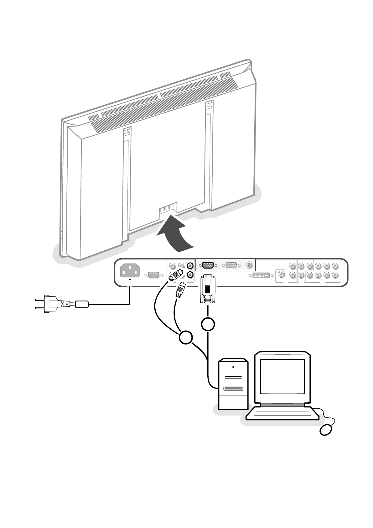
Connect your computer
Directly to the monitor
& Connect one end of a VGA cable 1 to the video card of the computer and
the other end to the
VGA 1 connector at the rear side of the monitor. Fix the
connectors firmly with the screws on the plug.
é In case of a Multimedia computer, connect the audio cable 2 to the audio
outputs of your Multimedia computer and to the
AUDIO VGA 1 R (right) and
L (left) inputs of the TV monitor.
VGA 2: The video connector for VGA 2 can be programmed to become an input or an
output via the Setup menu, see p. 8.The function of being input or output is
determined by the used mode. If the monitor is used in TV mode, the VGA2
connector is VGA output. If the monitor is used in monitor mode,the connector is VGA
input or output.
To a TV receiver box
See the handbook of the TV receiver box.
& Connect one end of a VGA cable to the video card of the computer and the
other end to the
PC/MAC IN connector at the rear side of the TV receiver
box. Fix the connectors firmly with the screws on the plug.
é In case of a Multimedia computer, connect the audio cable to the audio
outputs of your Multimedia computer and to the
AUDIO IN R (right) and L
(left) inputs of the TV receiver box.
Note: Only use the VGA cable supplied with the monitor.
Daisy chaining
The Loop Through facility makes it possible to make a daisy chain with a
second monitor.
“ Connect one end of another VGA cable to the VGA 2 connector at the rear
side of the monitor and the other end to the
VGA 1 connector of a second
monitor.
‘ In case of a Multimedia computer, also connect audio cables to the AUDIO L
and R outputs of the original monitor and to the AUDIO L and R inputs of the
second monitor.
The RC out jack next to the
VGA 2 connector makes it possible to daisy chain
remote control signals to other equipment.
This output cannot be used to daisy chain a second monitor.
I
English
L
R
RS232
~ MAINS
VGA 1
VGA 1
VGA 1VGA 2DVI-D
AUDIO
RC-OUT
VGA 2
L
R
Y/C S-VHS
AUD
DVI-D
AV2
1
2
Page 9

44
VGA 640x480 60, 72, 75, 85 Hz
Wide VGA 848x480 60 Hz
Wide VGA 852x480 60 Hz
MAC 640x480 66.67 Hz
MAC 832x624 74.55 Hz
MAC 1024x768 74.93 Hz
MAC 1152x870 75 Hz
SVGA 800x600 56, 60, 72, 75, 85 Hz
XGA 1024x768 60, 70, 75, 85 Hz
SXGA 1280x1024 60 Hz,
72 Hz (not with DVI-D source)
When a VGA computer is connected, the display selection is made
automatically.
A message is displayed when the monitor does not support the connected
VGA mode. Switch your computer to a correct display mode.
R6 / AA
B
Computer Display modes
Operation
& Insert the mains plug supplied into the mains inlet at the back of the
monitor and in the wall socket. For safety, please, only use the supplied rimearthed mains cord which has to be inserted in a grounded socket.
é Remote control: remove the cover of the battery compartment.
Insert the 2 batteries supplied (Type LR6/AA-1.5V).
The batteries supplied do not contain the heavy metals mercury and cadmium.
Nevertheless in many countries batteries may not be disposed of with your
household waste. Please check on how to dispose of batteries according to local
regulations.
“ Make sure that your TV receiver box and/or PC are switched on and that
your PC is in the correct display mode.
‘ Switch the monitor on : Press the power key B at the right side of the
monitor.
A green indicator lights up and the screen comes on.
When the monitor does not receive a supported VGA signal and is not
connected to a receiver box, the screen switches to standby and the red
indicator lights up.
When you switch on your monitor for the first time, and the monitor is
not connected to a TV receiver box, the language menu automatically
appears on the screen.The explanation appears in different languages one at
a time.
Follow the instructions on screen to select the correct language or see
Setup menu, Language, p. 8.
Page 10

5Use of the remote control 5
POWER
BRIGHTNESS
CONTRAST
ZOOM OUTZOOM INZOOM ON/OFF
VGA AV1 AV2 AV3
MUTE
AV MUTE
q
1
2
3
4
5
6
7
8
9
0
V
CH/PR
MENU
OK
¬
B
VGA
press repeatedly to select your computer
connected to the
VGA 1 or 2 connector or
to the
DVI-D connector.
AV1 , AV 2, AV3
press to select the peripherals connected
to the connector indicated on the monitor.
V press - or + to adjust the volume
¬ Mute button
Mute the sound or restore it
CH/PR Program selection
To browse through the sources selected.
B to switch to standby or on again
MENU to switch the menu on/off
cursor buttons to select your choice and
to alter a selected adjustment.
OK to activate your choice
AV MUTE to mute the picture and the
sound or restore it (if the monitor is
used in monitor mode).
When activated a green indicator starts
blinking in front of the monitor.
q Picture format
See Picture 2 menu, p. 7.
Press the q button to switch between
the different picture formats.
BRIGHTNESS +/-
to adjust the brightness level of the picture
CONTRAST +/-
to adjust the contrast level of the picture
ZOOM ON/OFF
to activate/de-activate the zoom function.
See p. 7.
ZOOM IN/OUT to adjust the zoom factor
and to change the magnification of the
picture when zoom is activated. See p. 7.
Use of the remote control
On screen information
When the monitor is used in the monitor mode, information about the active
source (
AV1 , AV2, AV3 , VGA1, VGA2 or DVI-D), and the supported video,VGA or
HD-format of the selected source is displayed on the screen together with the
selected picture format and icons informing about selected sound mode and AV or
audio mute.
Page 11

6
Use of the menus
Use of the menus and the menu system
& Press the MENU button on the remote control to summon the different
menu headers.
é Press the cursor left/right to move the cursor horizontally through the menu
headers.
“ Press the cursor down to access the menu.
In case of a slider, move the cursor left/right to adjust.
In case of a list with options, move the cursor right to enter and use the
cursor up/down to select an option.
Press the cursor left to leave the options list.
‘ Press the MENU button again to switch off the menu.
Note: Sometimes not all the menu items are visible on the screen.
Press the cursor down until all the items are displayed.
Only when the US English language has been selected (see Setup menu,
Language, p. 8), the menu items will be displayed with additional icons.
Operation
Press the MENU button on the remote control to summon the main menu.
Picture 1 menu
Brightness
This control allows you to adjust the brightness level of the picture.
Contrast
This control allows you to adjust the contrast level of the picture.
Color (only available when the source is
AV1, AV2 or AV3 YCbCr)
This control allows you to adjust the saturation level of the colors to suit
your personal preference.
Color temperature
This control allows you to select the color temperature of the picture.
Move the cursor up/down to make a selection.
Press the cursor left to return to the Picture 1 menu.
Tint (only with NTSC signals and when the source is
AV1 or AV2)
This control allows you to compensate for the color variations in NTSC
encoded transmissions.
Sharpness
This control allows you to adjust the edge definition of a picture.
Brightness
G
Contrast
H
(Color)
C
Color temp.
@
(Tint)
è
Sharpness
à
Picture 1 Picture 2 Sound M Setup º
Brightness
G
Contrast
H
Color
C
Color temp.
@
(Tint)
è
Sharpness
à
Picture 1
Brightness
G
Contrast
H
Color temp.
@
Sharpness
à
Picture 1
SD video-mode
VGA-mode + HD video mode
Page 12
7Use of the menus
Picture 2 menu
Zoom
Select
Zoom On to activate the zoom function.
You may also activate the zoom function with the
ZOOM ON/OFF button on
the remote control.
If no zoom is active, press the cursor left/right, up/down to select which part
of the screen will be zoomed.
Zoom factor
Select
Zoom factor and press the cursor left/right to adjust the zoom factor
and to change the magnification of the picture.
If zoom is not active, changing the magnification factor will have no effect on
the displayed picture.
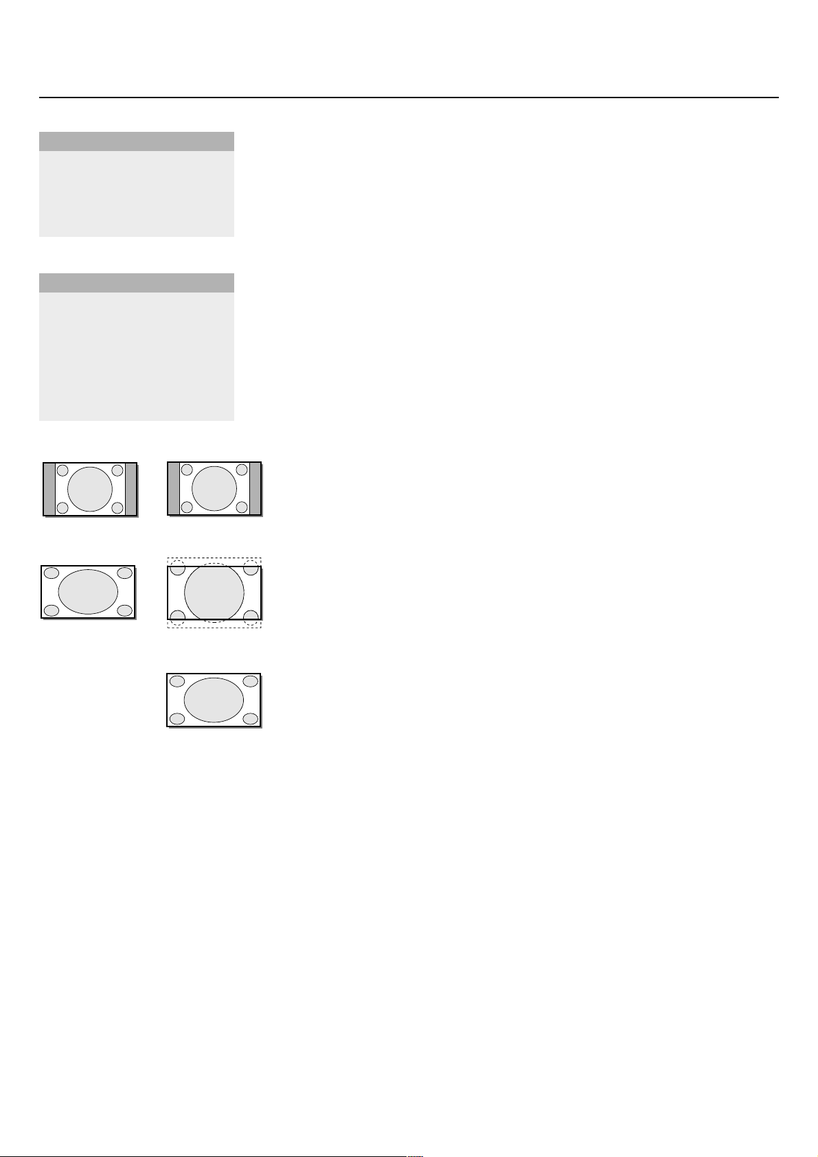
Format (only available in 4:3 VGA mode and SD video mode)
Select
Format to summon a list of available display formats.
Press the cursor up/down to select another display format: 4:3,
Movie expand 16:9 or Wide screen.
Note: Movie expand 16:9 is not available in VGA mode.
Shift (only available in VGA mode on VGA1 or VGA2 and in one of the HD modes.
See Connect Peripheral Equipment, p. 9.)
This control allows you, when necessary, to move the picture in a horizontal
or vertical way.
& Use the cursor left/right, up/down to adjust.
é Press the OK button when done.
Clock frequency (only available in VGA mode on VGA 1 or VGA 2.
See Connect Peripheral equipment, p. 9.)
This control allows you, when necessary, to adjust the values of the clock
frequency so that especially text can be displayed with an optimal overall
sharpness.
Use the cursor left/right to adjust.
Phase (only available in VGA mode on VGA 1 or VGA 2.
See Connect Peripheral equipment, p. 9.)
This control allows you, when necessary, to adjust the pixel phase of the
picture to avoid picture interference.
Use the cursor left/right to adjust.
Auto align (only available in VGA mode on VGA1 or VGA2 and in one of the HD
modes. See Connect Peripheral Equipment, p. 9.)
This control allows you to automatically adjust the shift, the clock frequency
and the phase in VGA mode and the shift in HD modes.
Press OK to execute.
Format
q
4:3
Movie expand 16:9
Wide screen
Zoom
Z
Zoom factor
Â
Picture 2
(Format)
q
4:3
Wide screen
Zoom
Z
Zoom factor
Â
(Shift)
‹
(Clock frequency)
S
(Phase)
fi
(Auto align)
X
Picture 2
SD video-mode
SD video-mode
4:3 VGA-mode
VGA-mode + HD video mode
4:3
4:3
Wide screen
Movie expand 16:9
Wide screen
Page 13

8
Use of the menus
Sound menu
Volume
This control allows you to adjust the volume level of the sound from the
speakers.
Bass
Bass attenuates or amplifies the low-frequency response of the sound from
the loudspeakers.
Treble
Treble attenuates or amplifies the high-frequency response of the sound
from the loudspeakers.
Sound mode
This control allows you to switch between mono and stereo sound.
Note: Bass,Treble and Sound mode will not be available in VGA loop through mode,
i.e. when a TV receiver box is connected to the monitor and a VGA source is
selected.
Setup menu
Language
& Use the cursor down to select Language.
é Press the cursor right to enter the list of selectable languages.
“ Use the cursor up/down to scroll through the list and to bring up other
languages which are not displayed on the screen at present.
Note: Only with the US English language, the menu items will be displayed with
additional icons.
Power savings
This control allows you to overrule the automatic power savings feature.
In case
Power savings is switched Off, the power always remains on until the
monitor is forced to standby.
& Use the cursor down to select Power savings.
é Press the cursor left/right to select On or Off.
AV3
This control allows you to set the AV3 input to HD-RGB,YCbCr or HDYPbPr. When having selected
Auto, the monitor makes the selection
automatically between YCbCr, HD-YPbPr or HD-RGB.
See also p. 9, Equipment with Component Video Output connectors.
& Use the cursor down to select AV 3.
é Press the cursor right to enter the list with options.
“ Press the cursor up/down to select one of the options.
VGA2
This control allows you to select whether to set the VGA2 connector as
input, output or even HD-input.
& Use the cursor down to select VGA2.
é Press the cursor right to enter the list with options: VGA IN, VGA OUT or
HD IN.
“ Press the cursor up/down to select one of the options.
Note: AV3 and VGA2 will not be available in VGA loop through mode, i.e. when a TV
receiver box is connected to the monitor and a VGA source is selected.
Volume
V
Bass
-
Treble
+
Sound mode
J
Sound M
Language ‡US English
Power savings
)
English
AV3
(
Nederlands
VGA2
§
Deutsch
Français
Español
Setup º
Page 14

9
Connect Peripheral Equipment
You may connect 3 possible VGA sources (VGA1, VGA2 or DVI-D) and
3 possible video sources (
AV1 , AV2 and AV3 ) to the monitor.
The following diagrams show you where you can connect your peripheral
equipment.
Note: in case the monitor is operating in combination with a TV receiver box (TV
mode), the AV inputs on the monitor will be disabled and the VGA2 connector
becomes an output.
Equipment with Y/C-SVHS output connectors
& Connect the video cable to the AV 2 connector.
é Connect the audio cables to the equipment’s AUDIO L and R sockets and to
the
AUDIO L and AUDIO R AV2 sockets on the monitor.
Equipment with CVBS output connectors
& Connect the video cable to the AV 1 connector.
é Connect the audio cables to the equipment’s AUDIO L and R sockets and to
the
AUDIO L and R AV1 sockets on the monitor.
Equipment with Component Video Output connectors
Note: AV3 can handle the following video signals: YCbCr, HD-YPbPr and HD-RGB.
The discrimination between the various input formats and the appropriate video
processing is done automatically. It is however possible to overrule the automatic
detection. See Setup menu, p. 8.
& Connect the video cables of your equipment with YPbPr output with
composite sync on Y, or of your equipment with YCbCr output with
composite sync on Y to the YPbPr, resp.YCbCr input
AV3 IN sockets of the
monitor.
é Connect the video cables of your equipment with RGB output with separate
Horizontal and Vertical sync to the RGB input sockets and to the H and V
sockets
AV3 of the monitor.
“ Connect the audio cables to the equipment’s AUDIO L and R sockets and to
the
AUDIO IN L and AUDIO IN R AV3 sockets on the monitor.
Note: when High Definition signals are inputted to the monitor via the YPbPr/RGB
input, the monitor switches to the HD Video Mode.
The following HD and SD video modes are supported by the monitor on the YPbPr,
RGB and VGA2 HD input:
1920x1080/60I 720x480/60P
1280x720/60P 720x576/50P
The following SD video modes are supported by the monitor on theYCbCr input:
720x480/60I
720x576/50I
Note: you should make the correct selection for AV3 in the Setup menu, p. 8.
L
R
~ MAINS
AV 2
MAINS INLET
RS232
RC OUT
LRLRL
VGA 1
VGA 2
L
LCVBSPb H
R
VGA 1VGA 2DVI-D
Y/C
YPrVLRR
DVI-D
R
RS232
AUDIO
VGA 1 VGA 2
VGA 1VGA 2DVI-D
RC-OUT
DVI-D
AV2
Y/C S-VHS
AV2 AV1 AV 3
CVBS B/Pb/Cb
L
R
AUDIO IN AUDIO IN
AUDIO IN
G/Y/Y
R/Pr/Cr V
H
L
R
~ MAINS
L
R
RS232
AUDIO
VGA 1 VGA 2
VGA 1VGA 2DVI-D
RC-OUT
Y/C S-VHS
DVI-D
AV1
CVBS B/Pb/Cb
L
R
AUDIO IN AUDIO IN
AUDIO IN
G/Y/Y
AV2 AV1 AV 3
R/Pr/Cr V
H
L
R
L
R
Y/C S-VHS
AUDIO IN AUDIO IN
AV2 AV1 AV 3
~ MAINS
L
R
RS232
AUDIO
VGA 1 VGA 2
VGA 1VGA 2DVI-D
RC-OUT
DVI-D
AUDIO IN
CVBS B/Pb/Cb
G/Y/Y
R/Pr/Cr V
AV3
H
L
R
Page 15

10
High Definition equipment with VGA connector
& Connect the VGA output of your equipment to the VGA2 connector.
é Connect the audio cables to the equipment’s AUDIO L and R sockets and to
the
VGA2 AUDIO L and R sockets on the monitor.
Note: you should select
HD IN for VGA2 in the Setup menu. (See p. 8.)
Digital DVI output of your PC (DVI-D) or DVD player
& Connect the Digital DVI output of your PC or DVD-player to the DVI-D
connector.
é Connect the audio cables to the DVI-D AUDIO L and R sockets on the
monitor.
RC out connector
This connector allows you to daisy chain remote control signals to other
equipment (e.g. AV receiver, IR repeater) which have an electrical RC in.
Note: it is not possible to daisy chain a second monitor.
Serial I/O port RS232
The RS232 connector is only to be used with the monitor as stand alone.
This connector allows you to control the monitor via your PC (as a
replacement of the remote control).
Note:This connector can also be used for dealer service tools.
L
R
~ MAINS
RS232
VGA 1VGA 2DVI-D
AUDIO
VGA2
VGA 1 VGA 2
RC-OUT
H
CVBS B/Pb/Cb
L
R
Y/C S-VHS
AUDIO IN AUDIO IN
DVI-D
AUDIO IN
G/Y/Y
AV2 AV1 AV 3
R/Pr/Cr V
VGA2
H
CVBS B/Pb/Cb
L
R
Y/C S-VHS
AUDIO IN AUDIO IN
AUDIO IN
AV2 AV1 AV 3
G/Y/Y
R/Pr/Cr V
~ MAINS
L
R
RS232
AUDIO
VGA 1 VGA 2
VGA 1VGA 2DVI-D
RC-OUT
DVI-D
DVI-DDVI-D
L
R
L
R
L
R
~ MAINS
RS232
VGA 1 VGA 2
VGA 1VGA 2DVI-D
AUDIO
RC-OUT
RC-OUT
H
CVBS B/Pb/Cb
L
R
Y/C S-VHS
AUDIO IN AUDIO IN
DVI-D
AUDIO IN
G/Y/Y
AV2 AV1 AV 3
R/Pr/Cr V
L
R
~ MAINS
RS232
RS232
AUDIO
VGA 1VGA 2DVI-D
VGA 1 VGA 2
RC-OUT
L
R
Y/C S-VHS
AUDIO IN AUDIO IN
DVI-D
AUDIO IN
AV2 AV1 AV 3
CVBS B/Pb/Cb
G/Y/Y
R/Pr/Cr V
H
L
R
L
R
Page 16

11
Ambient temperature
Do not hang up the monitor above a
central heating or other heating sources.
Care of the screen
Clean the anti-reflex coated flat glass
screen with a slightly damp soft cloth. Do
not use abrasives solvents as it can
damage the glass surface of the screen.
Plasma Display characteristics
Caution:A video source (such as a video
game, DVD, or TV information channel)
which shows a constant non-moving
pattern on the TV screen, can cause
damage to the screen.When your Flat-TV
is continuously used with such a source,
the pattern of the non-moving portion of
the game (DVD, etc.) could leave an image
permanently on the screen.When not in
use, turn the video source OFF.
Regularly alternate the use of such video
sources with normal TV viewing.
When switching over to another picture
after having displayed the same still picture
for a long time (many hours), it may
happen that some parts from the previous
picture will remain on screen due to a
kind of memory effect.This ghost picture
will disappear after some time.To avoid
this effect change the pictures regularly or
for PC use you can turn on a screen saver
in your computer.
Philips has built in an automatic shift of
the picture in video mode every 5 minutes
to decrease this effect and to prolong the
life of the screen.
Very incidentally and after a longer period
of unuse (approx. 1 year) the screen may
display some strange color deficiencies.
This is quite normal for plasma displays
and these effects will disappear after the
set has been turned on for some time.
A plasma display consists of more than
3.1 Million color pixels. It is within
industry standards that very few pixels (<
0.001%) may be defective, even for a new
set.There is however no reason to doubt
about the quality of the set.
The plasma display technology operates
with rare gases which are being influenced
by air pressure.
Up to an altitude of 6562 ft above sealevel, the display is functioning fine.
Operating the set at a higher altitude, the
picture becomes unstable and the picture
performance is deteriorating. After
bringing the set below 6562 ft it works
fine again.Transportation has no influence.
Control of peripheral equipment
The infrared radiation of the screen may
influence the reception sensitivity of other
peripherals. Solution: replace the batteries
of the remote control or change position
of other equipment. E.g. keep away a
wireless headphone from within a radius
of 4.92 ft.
No stable or not synchronized VGA
picture
Check if you have selected the correct
display mode in your PC. See p.4,
Computer display modes.
No picture or no sound
Are the supplied cables connected
properly? (The power cable to the display,
the VGA cables, the audio cables,...)
Is your PC switched on?
Do you see a black screen and the
indicator in front of the monitor lights up
green, this means that the display mode is
not supported.
Switch your VGA source to a correct
mode.
Remote control
If your monitor no longer responds to the
remote control, the batteries may be
exhausted.
If your problem is not solved:
Switch your monitor off and then on
again.
Never attempt to repair a defective
monitor yourself.
Check with your dealer or call a TV
technician.
Transport
Keep the original packaging to transport the
monitor if needed.
End of life directives
Philips is paying a lot of attention to
produce environmentally-friendly in green
focal areas.Your new monitor contains
materials which can be recycled and
reused.
At the end of its life specialized companies
can dismantle the discarded monitor to
concentrate the reusable materials and to
minimize the amount of materials to be
disposed of.
Please ensure you dispose of your old
monitor according to local regulations.
How to dispose of batteries ?
The batteries supplied do not contain the
heavy metals mercury and cadmium.
Nevertheless in many countries batteries
may not be disposed of with your
household waste. Please ensure you dispose
of batteries according to local regulations.
Miscellaneous
. Ambient temperature: + 5~ + 40°C
. Maximum operating altitude:
2000 m/6562 ft (min. pressure 800h Pa)
. Mains: AC 95-264V 50/60 Hz
. Power consumption:
± 250 W (32”) or ± 320 W (42”)
. Standby consumption: < 2 W
. Weight (excl. packaging)
Display: 53 (32”) or 79 (42”) Lbs
. Dimensions (wxhxd):
Display: 38 x 20,2 x 3,5 inch (32”)
or 47,8 x 25,9 x 3,5 inch (42”)
. Wall mounting bracket included
Tips
Page 17

 Loading...