

Philips 311 Service Manual
Départ. Technical support- CM640 PROCEDURE COMPANY RESTRICTED
PHILIPS Consumer
Communications
Centre du Mans
Service Repair Support
SERVICE MANUAL
Repair for Cellular Telephone
Fisio 311
LEVEL 1 / LEVEL 2
VY-V-640-204
Page : 1 of 42
Langue : EN
Date : 09/21/01
PHILIPS ELECTRONICS N.V. 1999 VY-V-640-204
All rights reserved. Reproduction in whole
or in part is prohibited without the written
consent of the copyright owner.

Départ. Technical support- CM640 PROCEDURE COMPANY RESTRICTED
PHILIPS Consumer
Communications
Centre du Mans
Last updates :
DATE MODIFICATION PAGE
07/09/00 REVISION 1
REVISION 2 : 21/09/01
Service Repair Support
SERVICE Manual
Code Nomenclature suppressed
N° 4311 256 03841 : Sticker Process
VY-V-640-204
Page : 2 of 42
Langue : EN
Date : 09/21/01
Page : 39
PHILIPS ELECTRONICS N.V. 1999 VY-V-640-204
All rights reserved. Reproduction in whole
or in part is prohibited without the written
consent of the copyright owner.

Départ. Technical support- CM640 PROCEDURE COMPANY RESTRICTED
PHILIPS Consumer
Communications
Service Repair Support
VY-V-640-204
Page : 3 of 42
Centre du Mans
Langue : EN
Date : 09/21/01
CONTENTS
1.0 PURPOSE..............................................................................................................................................................................................4
2.0 SCOPE....................................................................................................................................................................................................4
3.0 REFERENCE........................................................................................................................................................................................4
4.0 GLOSSARY/ACRONYM LIST......................................................................................................................................................4
5.0 TEST EQUIPMENT AND TOOLS ...............................................................................................................................................4
6.0 TEST AND INPECTION PLAN.....................................................................................................................................................5
6.1 User Interface Test............................................................................................................................................................................5
6.2 RF Test ................................................................................................................................................................................................5
7.0 BEFORE STARTING........................................................................................................................................................................6
7.1 Description Of The Transceiver.....................................................................................................................................................6
7.2 Description Of The Display.............................................................................................................................................................7
7.3 Using The Carousel..........................................................................................................................................................................8
7.4 Inserting The MICRO-Card.............................................................................................................................................................9
7.5 Inserting The Battery........................................................................................................................................................................9
7.6 Attach The Battery Cover................................................................................................................................................................9
7.7 Removing The Battery ...................................................................................................................................................................10
7.8 Charging The Battery .....................................................................................................................................................................10
7.9 W@P Introduction..........................................................................................................................................................................11
8.0 TEST PROCEDURES......................................................................................................................................................................13
8.1 Initial Functional Check for Fisio 311.........................................................................................................................................13
8.2 RF Test ..............................................................................................................................................................................................16
8.3 Battery Charging (IGN : Ignition) / Current Consumption......................................................................................................20
8.4 W@P Test Procedure .....................................................................................................................................................................22
9.0 ASSEMBLY / DISMANTLEMENT PROCEDURES.............................................................................................................28
9.1 Dismantlement ................................................................................................................................................................................. 28
9.2 Assembly ..........................................................................................................................................................................................32
9.3 Exploded view of the transceiver.................................................................................................................................................36
10.0 SOLUTIONS IN CASE OF PROBLEMS DURING THE TESTS ......................................................................................37
11.0 RECOMENDED PART LIST CT2888 FISIO311 .................................................................................................................39
11.1 Common Parts - Out Of Warranty...............................................................................................................................................39
11.2 Specific Parts - Out Of Warranty.................................................................................................................................................40
11.3 Common parts – in warranty.........................................................................................................................................................41
ANNEX 1...........................................................................................................................................................................................................42
PHILIPS ELECTRONICS N.V. 1999 VY-V-640-204
All rights reserved. Reproduction in whole
or in part is prohibited without the written
consent of the copyright owner.

Départ. Technical support- CM640 PROCEDURE COMPANY RESTRICTED
PHILIPS Consumer
Communications
Service Repair Support
VY-V-640-204
Page : 4 of 42
Centre du Mans
Langue : EN
Date : 09/21/01
1.0 PURPOSE
This document establishes the functional test and inspection procedures for the first level service repair of the
FISIO 311 transceiver.
2.0 SCOPE
The test plan is applicable to all levels of service repair of the FISIO 311 transceiver.
3.0 REFERENCE
None.
4.0 GLOSSARY/ACRONYM LIST
Window or Bezzel Protective plastic over the LCD display
SW Software
PN Hardware Configuration of the Mobile
CN Matrix for Types of SW used on the different hardware
HW Hardware
ASC Authorized Service Center
NSC National Service Center
Test SIM Card Used for functionality of PHILIPS Mobile Phones
Test SIM Card « SP » SIM Card used to simulate the user interface and enable radio tests
5.0 TEST EQUIPMENT AND TOOLS
Equipment / Tools
- Production Test SIM Card - Part No. : 4311 255 00781
- Test SIM Card « SP » - Part No. : 4311 255 00782
- Digital Multimeter - Recommended Model : Fluke
Specification with current reading in mA.
- Digital Radiocommunication Tester.
- Coupling system with shielded chamber.
Or
- RF Cable - Part No.: 941-555-1(AMP)
(No mechanical adaptation provided by Philips.)
PHILIPS ELECTRONICS N.V. 1999 VY-V-640-204
All rights reserved. Reproduction in whole
or in part is prohibited without the written
consent of the copyright owner.
Départ. Technical support- CM640 PROCEDURE COMPANY RESTRICTED
PHILIPS Consumer
Service Repair Support
Communications
Centre du Mans
6.0 TEST AND INPECTION PLAN
The test plan is derived from the Product Test Reference of FISIO 311.
6.1 User Interface Test
Use the Test SIM Card « SP »/ Production to test the transceivers as follows :
• On/Off button
• LCD Backlight
• Keyboard Test
• Buzzer Test
• Vibrator Test
• Audio Test
• Antenna Test ( to measure the radiated power level. Not necessary when using an antenna coupler)
• LCD
• IMEI
• Tester Status/Eeprom Status
VY-V-640-204
Page : 5 of 42
Langue : EN
Date : 09/21/01
With a fast Charger connected with the PRODUCT’s bottom connector , check the full scrolling from one mode to
the next when charging IGN (Ignition) – Battery.
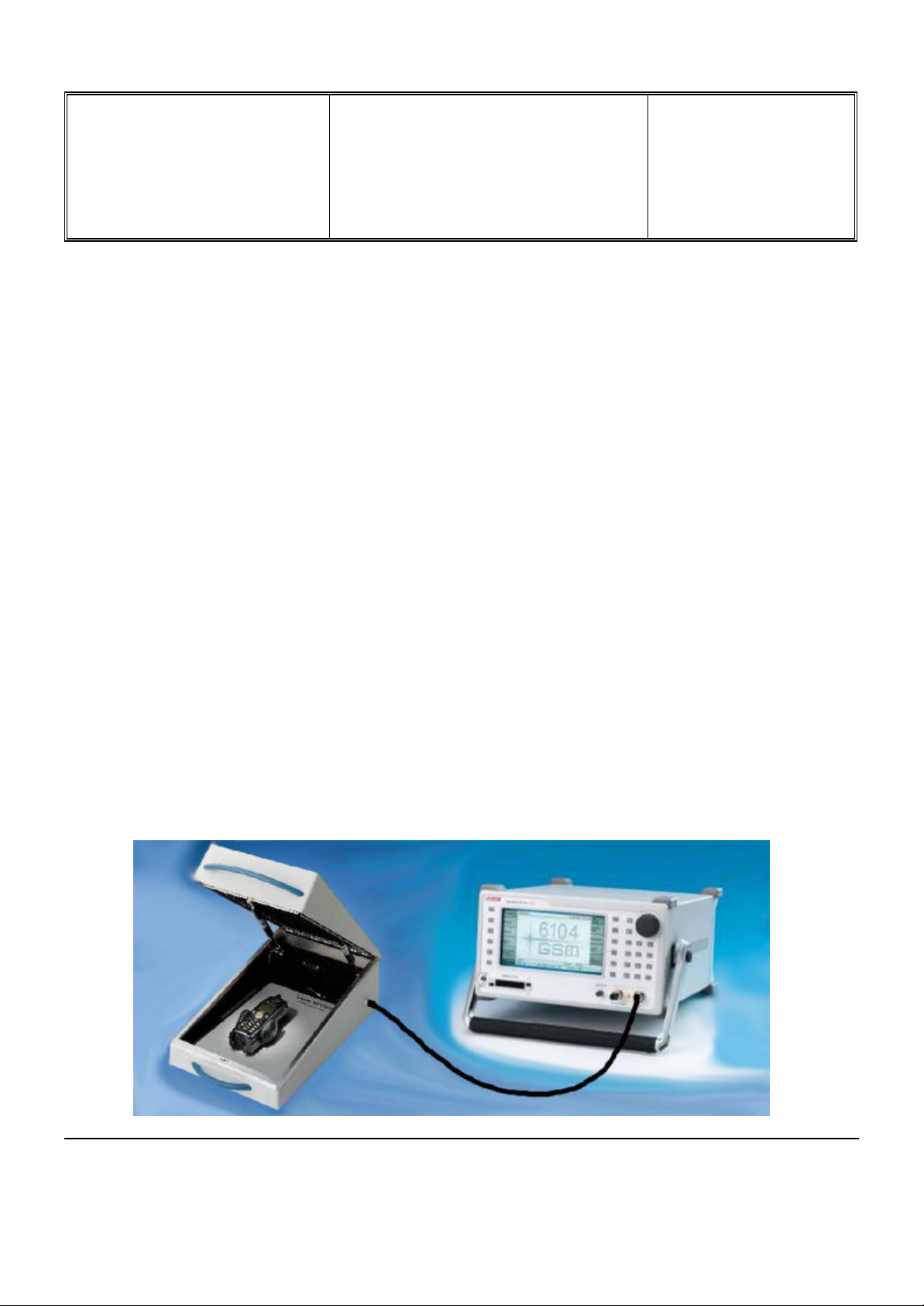
6.2 RF Test
The radio test must be performed with a Digital Radio Test Set. The mobile has to be set on the antenna coupler
inside the shielded chamber.
PHILIPS ELECTRONICS N.V. 1999 VY-V-640-204
All rights reserved. Reproduction in whole
or in part is prohibited without the written
consent of the copyright owner.
Départ. Technical support- CM640 PROCEDURE COMPANY RESTRICTED
PHILIPS Consumer
Communications
Centre du Mans
7.0 BEFORE STARTING
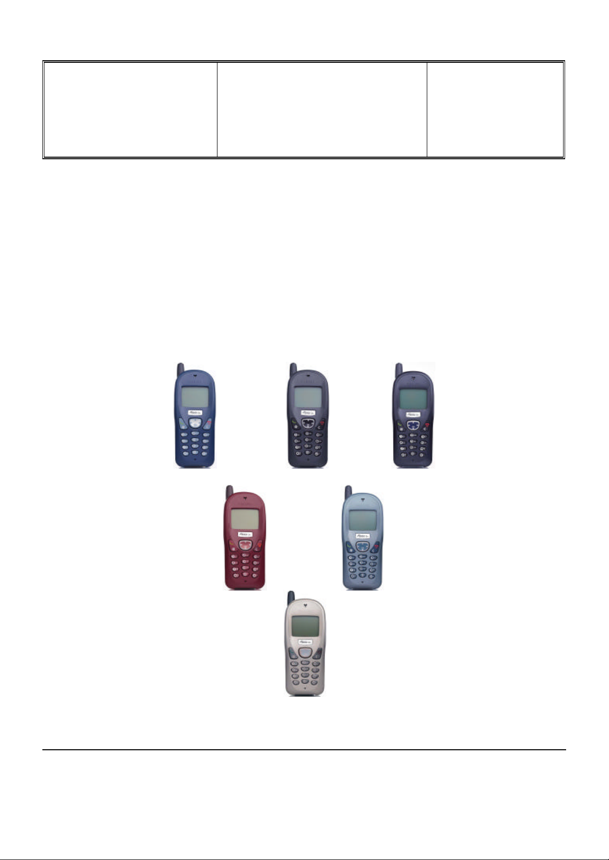
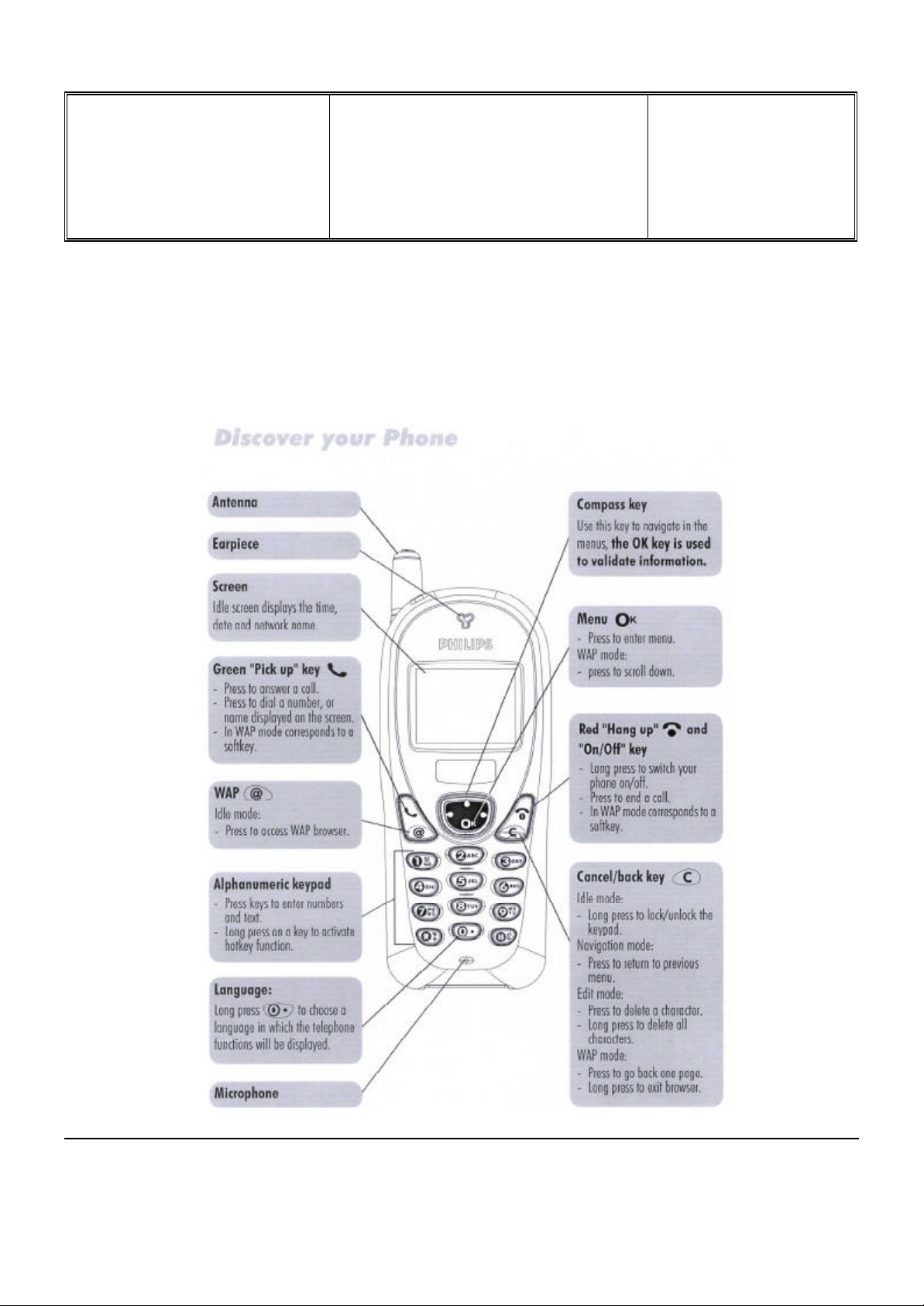
7.1 Description Of The Transceiver
Service Repair Support
VY-V-640-204
Page : 6 of 42
Langue : EN
Date : 09/21/01
PHILIPS ELECTRONICS N.V. 1999 VY-V-640-204
All rights reserved. Reproduction in whole
or in part is prohibited without the written
consent of the copyright owner.
Départ. Technical support- CM640 PROCEDURE COMPANY RESTRICTED
PHILIPS Consumer
Communications
Centre du Mans
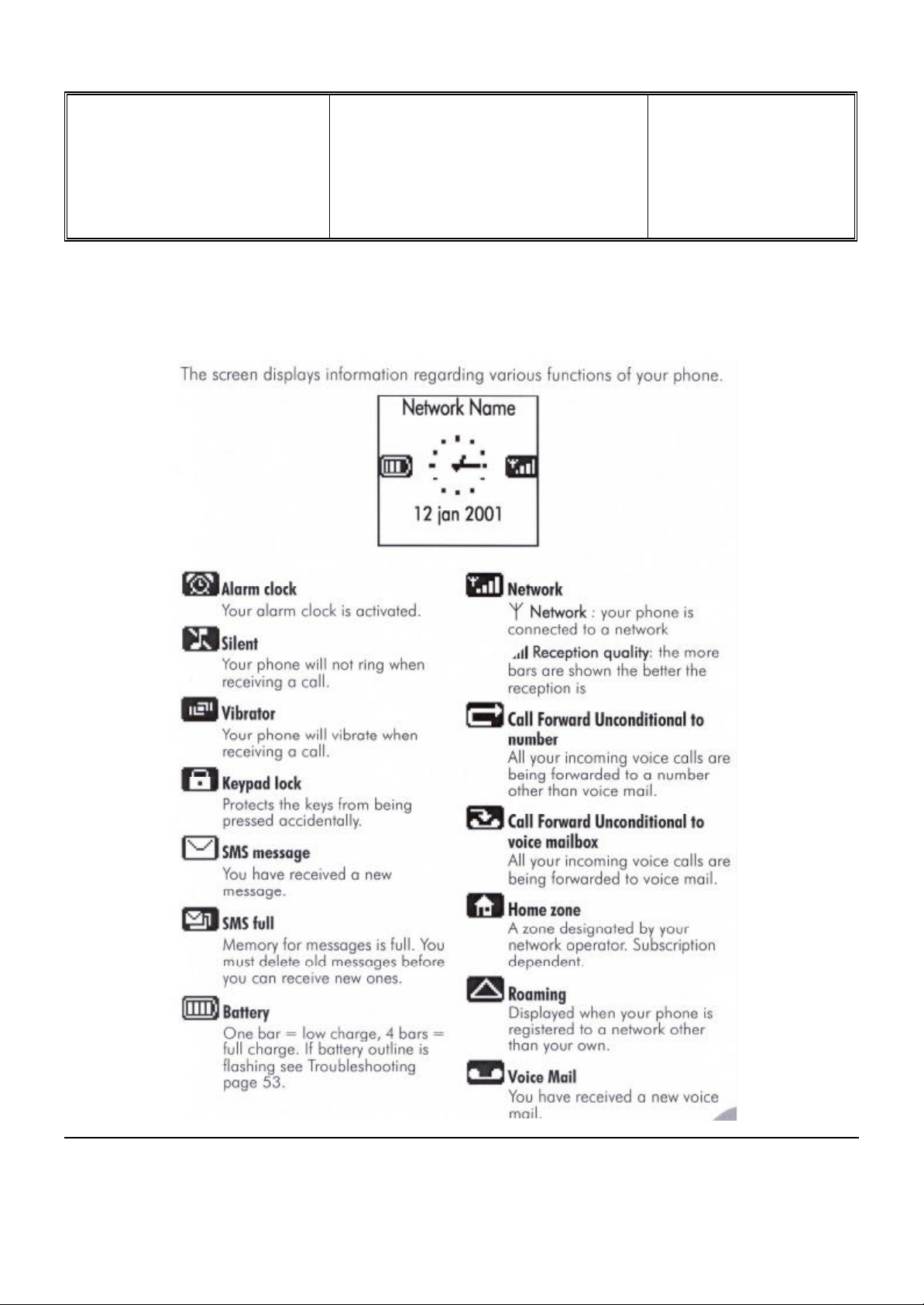
7.2 Description Of The Display
Service Repair Support
VY-V-640-204
Page : 7 of 42
Langue : EN
Date : 09/21/01
PHILIPS ELECTRONICS N.V. 1999 VY-V-640-204
All rights reserved. Reproduction in whole
or in part is prohibited without the written
consent of the copyright owner.
Départ. Technical support- CM640 PROCEDURE COMPANY RESTRICTED
PHILIPS Consumer
Communications
Service Repair Support
VY-V-640-204
Page : 8 of 42
Centre du Mans
Langue : EN
Date : 09/21/01
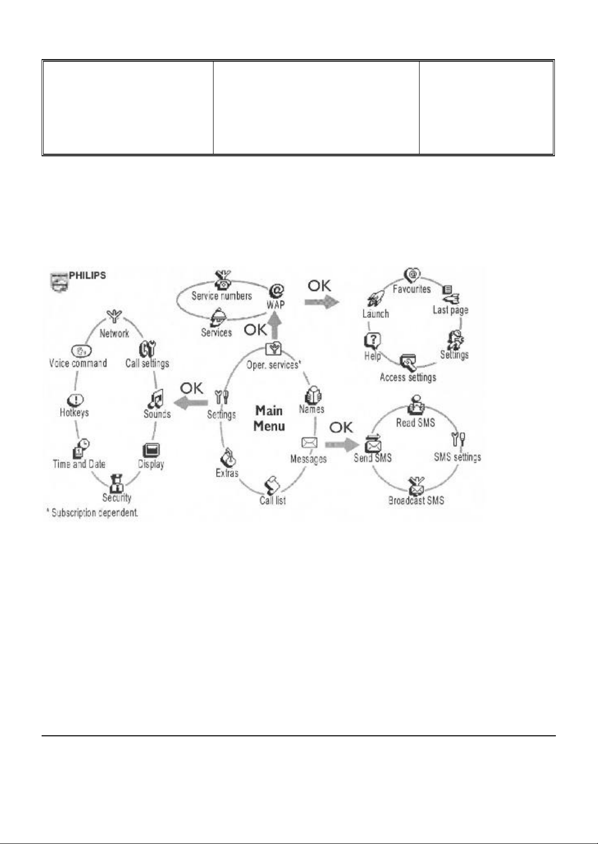
7.3 Using The Carousel
The carousel is a circular loop of icons displayed on the screen. These icons provide access to the different menus
and sub menus used to operate your phone.
PHILIPS ELECTRONICS N.V. 1999 VY-V-640-204
All rights reserved. Reproduction in whole
or in part is prohibited without the written
consent of the copyright owner.
Départ. Technical support- CM640 PROCEDURE COMPANY RESTRICTED
PHILIPS Consumer
Communications
Centre du Mans
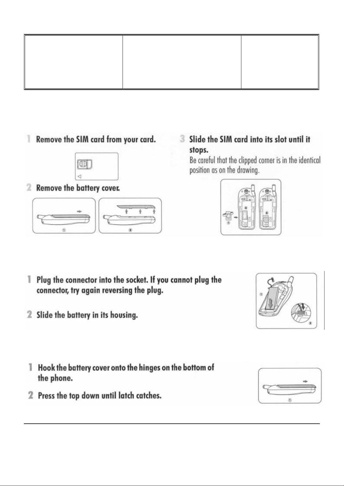
7.4 Inserting The MICRO-Card
Service Repair Support
VY-V-640-204
Page : 9 of 42
Langue : EN
Date : 09/21/01
7.5 Inserting The Battery
7.6 Attach The Battery Cover
PHILIPS ELECTRONICS N.V. 1999 VY-V-640-204
All rights reserved. Reproduction in whole
or in part is prohibited without the written
consent of the copyright owner.
Départ. Technical support- CM640 PROCEDURE COMPANY RESTRICTED
PHILIPS Consumer
Communications
Centre du Mans
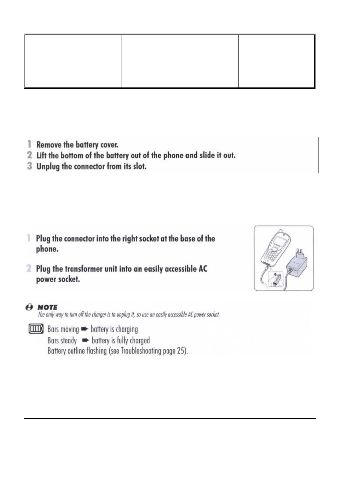
7.7 Removing The Battery
7.8 Charging The Battery
Service Repair Support
VY-V-640-204
Page : 10 of 42
Langue : EN
Date : 09/21/01
PHILIPS ELECTRONICS N.V. 1999 VY-V-640-204
All rights reserved. Reproduction in whole
or in part is prohibited without the written
consent of the copyright owner.
Départ. Technical support- CM640 PROCEDURE COMPANY RESTRICTED
PHILIPS Consumer
Communications
Service Repair Support
VY-V-640-204
Page : 11 of 42
Centre du Mans
Langue : EN
Date : 09/21/01
7.9 W@P Introduction
The purpose of W@p (Wireless Application Protocol) is to enable easy and fast delivery of relevant information and
services to mobile users. However, mobile Internet does not mean navigating on the Internet with a wireless device
but rather to access to some services in a mobile context.
The W@P architecture was designed to enable standard Internet servers to provide services to wireless devices.
The W@P wireless protocol is based on Internet standards such as HTTP and TLS but has been optimized
according to the constraints of the wireless terminals: low memory capacity, small screen size
and of the network: limited bandwidth.
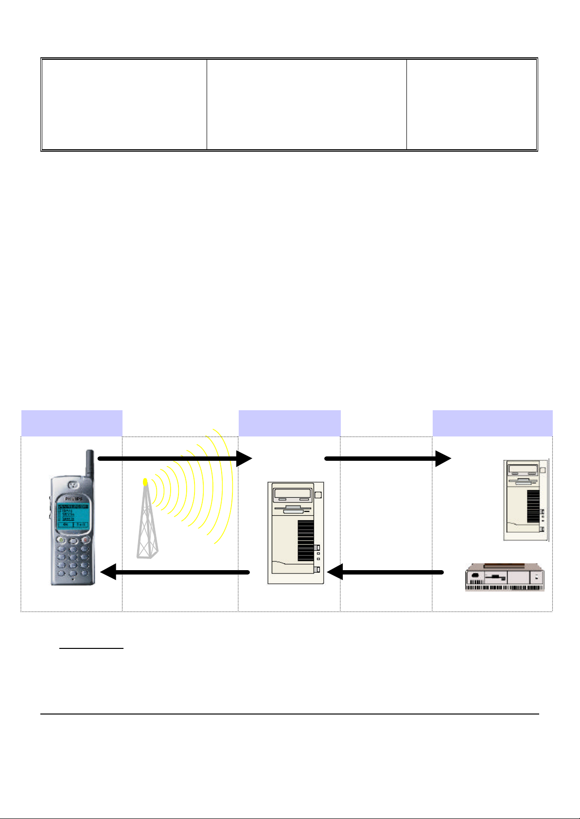
The W@P architecture is made up of 4 technological parts which are necessary for accessing W@P services on a
mobile phone. These are:
W@P navigator or browser
Mobile operator network
W@P gateway / W@P server
Web server
Customer Gateway Server
1.0 Encoded
Request
4.0 Encoded
Answer
* Subscription
The customer has to contact his Network Operator to inquire about his subscription and the options he can
subscribe to. Generally the customer just have to request his W@P access to his provider and he will not be
charged for that.
Encoder/
Decoder
2.0 Request
Content
Generation
3.0 Answer
PHILIPS ELECTRONICS N.V. 1999 VY-V-640-204
All rights reserved. Reproduction in whole
or in part is prohibited without the written
consent of the copyright owner.

Départ. Technical support- CM640 PROCEDURE COMPANY RESTRICTED
PHILIPS Consumer
Communications
Service Repair Support
VY-V-640-204
Page : 12 of 42
Centre du Mans
Langue : EN
Date : 09/21/01
* W@P parameters
Parameters have to be set in the mobile phone in order to access W@P services . However, there are two
cases depending on the commercial offer:
* Transceiver sold via an operator package(with subscription included):
- Parameters cannot be accessed from the W@P settings menu of the mobile phone:
The transceiver is W@P locked. The W@P connections will always be made from the
operator W@P homepage and search engines will be available. The customer will have to
ask for a password from his/her operator to unlock the W@P settings.
- Parameters can be accessed from the W@P settings menu of the mobile
phone:
The customer changes the W@P parameters according to his/her own convenience.
* Retail transceiver(without subscription included):
- Phones are configured by the manufacturer with no W@P parameter. The end user has
to ensure that the W@P functionalities and a data/fax options have been subscribed.
The end user has also to set the W@P parameters by asking for them from
his/her operator or by using parameters of another company (available on
Internet, newspaper etc.)
Detailed parameters
Phone Number (or dial-up number) : to establish a connection with the Internet Service Provider
Login (or User Name) : if requested by your ISP
The password : if requested by your ISP
IP address for the Gateway : for communications between Internet Service Provider and Gateway
& Port Number (for a secure or non secure connection)
Home page address(or URL address): for communications between Gateway and Web server
Please note that it is important to respect small and capital letters according to your operator instructions.
It is also possible that your provider does not require the Login and/or Password.
PHILIPS ELECTRONICS N.V. 1999 VY-V-640-204
All rights reserved. Reproduction in whole
or in part is prohibited without the written
consent of the copyright owner.

Départ. Technical support- CM640 PROCEDURE COMPANY RESTRICTED
PHILIPS Consumer
Communications
Service Repair Support
VY-V-640-204
Page : 13 of 42
Centre du Mans
Langue : EN
Date : 09/21/01
8.0 TEST PROCEDURES
8.1 Initial Functional Check for Fisio 311
8.1.1 Insert the Test Production Card into the SIM Reader at the back of the cellular phone and clip a charged
battery on the phone.
8.1.2 Press the «ON» button for 2 seconds at least and the LCD will show a message which contains information
of FA (Final Adjustment) status and 12NC.
8.1.3 Follow the instructions as mentioned below :
Step Procedure Observation
Press Key 1
1
2
3
Press Key 1 again.
Press key 2
(Audio loop local effect)
Press key 2 again
Press key 3
Audio loop test (Speak to Mic
and listen echo from Speaker)
Continue Buzzer signal
Left corner displays 1
00
"LocalEffect"
" XX XX XX“
“ XX XX”
Left corner displays 2
01
"AUDIO xx xx xx xx”
"EEP xx xx xxxx ”
Press key 3 again
Press key 4
Check for the Backlight
4
5
6
function in the same time.
Press key 4 again
Press Key 5
(Checkerboard test)
Press Key 5 again
Press Key 6
(Inverted Checkerboard)
Press Key 6 again
Left corner displays 3
02
Backlight must be on
Left corner displays 4
03
Checkerboard 1 pixel on
Left corner displays 5
04
Checkerboard 2 pixel on
Left corner displays 6
05
PHILIPS ELECTRONICS N.V. 1999 VY-V-640-204
All rights reserved. Reproduction in whole
or in part is prohibited without the written
consent of the copyright owner.
 Loading...