

Philips 2sc3423 DATASHEETS
TOSHIBA Transistor Silicon NPN Epitaxial Type (PCT Process)
2SC3423
2SC3423
Audio Frequency Amplifier Applications
• Complementary to 2SA1360
• Small collector output capacitance: C
• High transition frequency: f
= 200 MHz (typ.)
T
Maximum Ratings
Characteristics Symbol Rating Unit
Collector-base voltage V
Collector-emitter voltage V
Emitter-base voltage V
Collector current I
Base current I
Collector power
dissipation
Junction temperature T
Storage temperature range T
(Tc = 25°C)
Ta = 25°C 1.2
Tc = 25° C
Electrical Characteristics
= 1.8 pF (typ.)
ob
CBO
CEO
EBO
C
B
P
C
j
stg
(Tc = 25°C)
150 V
150 V
5 V
50 mA
5 mA
5
150 °C
−55 to 150 °C
W
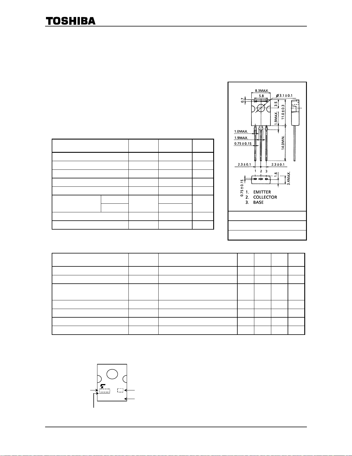
Unit: mm
JEDEC ―
JEITA ―
TOSHIBA 2-8H1A
Weight: 0.82 g (typ.)
Characteristics Symbol Test Condition Min Typ. Max Unit
Collector cut-off current I
Emitter cut-off current I
DC current gain
Collector-emitter saturation voltage V
Base-emitter voltage VBE VCE = 5 V, IC = 10 mA ― ― 0.8 V
Transition frequency fT VCE = 5 V, IC = 10 mA ― 200 ― MHz
Collector output capacitance Cob VCB = 10 V, IE = 0, f = 1 MHz ― 1.8 ― pF
VCB = 150 V, IE = 0 ― ― 0.1 µA
CBO
VEB = 5 V, IC = 0 ― ― 0.1 µA
EBO
h
FE
(Note)
CE (sat) IC
= 5 V, IC = 10 mA 80 ― 240
V
CE
= 10 mA, IB = 1 mA ― ― 1.0 V
Note: hFE classification O: 80 to 160, Y: 120 to 240
Marking
Lot No.
C3423
A line indicates
lead (Pb)-free package or
lead (Pb)-free finish.
Characteristics indicator
Part No. (or abbreviation code)
1
2004-07-07
2SC3423
56
48
40
(mA)
C
32
24
16
Collector current I
8
0
4 2
Collector-emitter voltage VCE (V)
56
48
40
(mA)
C
32
24
Tc = 100°C
16
Collector current I
8
0
0 0.6 0.8
Base-emitter voltage VBE (V)
1000
500
300
FE
100
50
DC current gain h
30
Tc = 100°C
10
0.3 3 10 30 1
Collector current IC (mA)
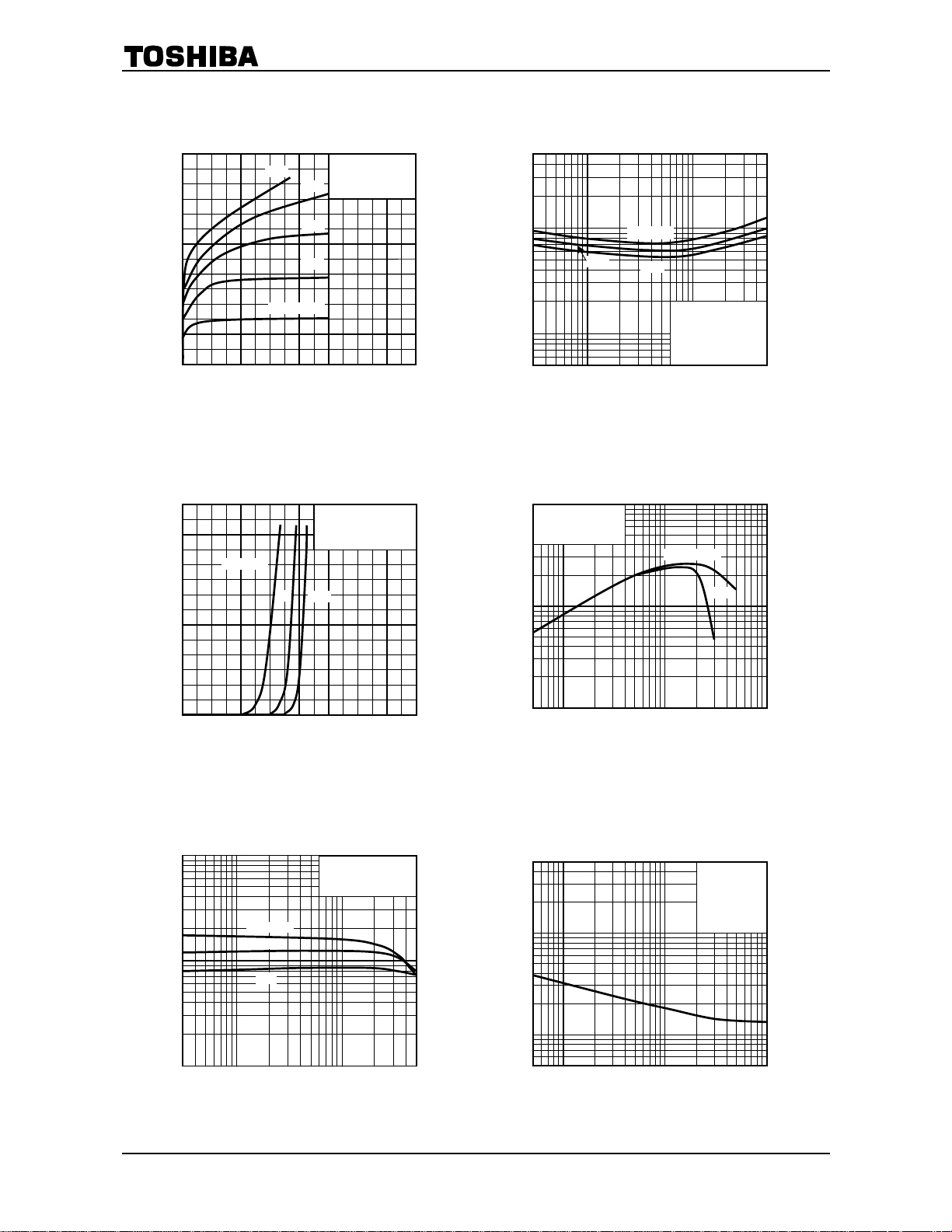
I
– VCE
C
0.5
IB = 0.1 mA
6 8
I
– VBE
C
25
h
FE
25
−25
Common emitter
Tc = 25 °C
0.4
0.3
0.2
12
10
Common emitter
VCE = 5 V
−25
1.2
1.0 0.4 0.2 1.4 1.6
– IC
Common emitter
VCE = 5 V
14 16
V
– IC
0.5
0.3
0.1
(V)
(sat)
0.05
CE
V
0.03
Collector-emitter saturation voltage
0.001
0
0.005
CE (sat)
Tc = 100°C
25
1
Collector current IC (mA)
−25
Common emitter
IC/IB = 10
3 10 30 0.3
50 0.5 5
f
– I
T
1000
Common emitter
Tc = 25°C
500
300
(MHz)
T
100
50
30
Transition frequency f
10
1 3 10 100 30 0.5
Collector current IC (mA)
C
VCE = 10 V
5
C
– VCB
50
30
(pF)
ob
10
5
50 5 0.5
Collector output capacitance C
3
1
0.5
1
0.5
Collector-base voltage VCB (V)
ob
IE = 0
f = 1 MHz
Tc = 2 5° C
3
10 30
100
2
2004-07-07
 Loading...