

Philips 2M1355-61652, M1356-61661, M1358-61681 User manual

1Service Supplement
2M1355-61652, M1356-61661 and M1358-61681
3Replacement Transducer Cables
Use the replacement transducer cables to repair BROWN transducers ONLY.
M1355-61652 is the replacement cable for the brown Toco transducer (M1355A).
M1356-61661 is the replacement cable for the brown Ultrasound transducer (M1356A).
M1358-61681 is the replacement cable for the brown US/MECG Combi transducer (M1358A).
CAUTION All blue M1355A, M1356A and M1358A transducers are sealed, watertight units and are NOT repairable.
Replacing the cable of a blue transducer, or modifying the transducer in any way, will void any warranty,
including the guarantee of watertightness.
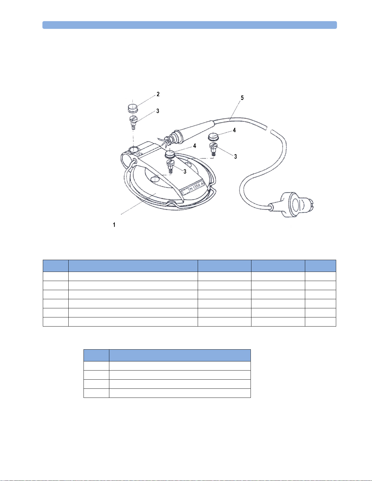
Dismantling the Ultrasound Transducer (Brown)
To dismantle the Brown ultrasound transducer, proceed as follows:
CAUTION Take care when removing the wires as they are thin and can easily be damaged.
1 Disconnect the transducer from the monitor.
2 Remove screw covers 1 and 2: press a flat screwdriver into the covers and prise them out.
NOTE When reassembling the transducer, you will need new screw covers as the old ones cannot be re-used.
3 Partially undo screws 3. The two halves of the transducer can now be separated by pressing down on the
screws.
4 Remove the screws 3 and pull the two halves of the cover apart.
Printed in Germany
March 2004
© 1990-2004 Koninklijke Philips Electronics N.V.
All Rights Reserved.
*M1350-9300A*
Part number M1350-9300A
4535 640 05271
5 Carefully disconnect the transducer cable from the crystal board: use a soldering iron to separate the
three cable wires from the board.
Re-assembly is a reversal of the above procedure.
Parts for the Ultrasound Transducer (M1356A)
Ultrasound Transducer: Parts List
Item Description
1 Case Top (US, Brown) M1356-44562 453563277221 1
2 Cover Screw (Red) M1356-44106 453563277211 1
3 Screw 0515-2121 453563024231 3
4 Cover Screw (Black) 5041-4274 453563099961 2
5 Cable Assembly (US) 2.5m / 8.2ft M1356-61661 453563277261 1
- Transducer Knob Adapters (not shown) M1356-43201 453563277191 3
Ultrasound Transducer: Cable Connections
Part Number 12NC
Pin Cable Color
4Brown
8Red
1+6 Bridged by Code Resistor 665
1Shield
Ω
Quantity
2
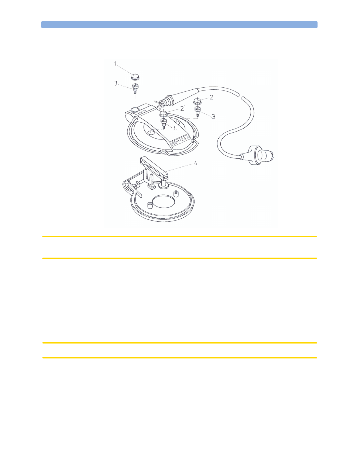
Dismantling the Toco Transducer (Brown)
CAUTION Take care when removing the wires as they are thin and can easily be damaged. NEVER pull the strain
gauge button.
1 Disconnect the transducer from the monitor.
2 Remove screw covers 1 and 2. Press a flat screwdriver into the covers and prise them out.
NOTE When reassembling the transducer, you will need new screw covers as the old ones cannot be re-used.
3 Partially undo screws 3. The two halves of the transducer can now be separated by pressing down on the
screws.
4 Remove the screws 3 and pull the two halves of the cover apart.
5 Disconnect the transducer cable from the strain gauge 4. Use a soldering iron to carefully separate the
three cable wires from the gauge.
CAUTION NEVER pull the strain gauge button.
6 Cut the clips holding the strain gauge and remove it.
7 Re-assembly is a reversal of the above procedure. The strain gauge assembly is a press fit into the
transducer cover.
3
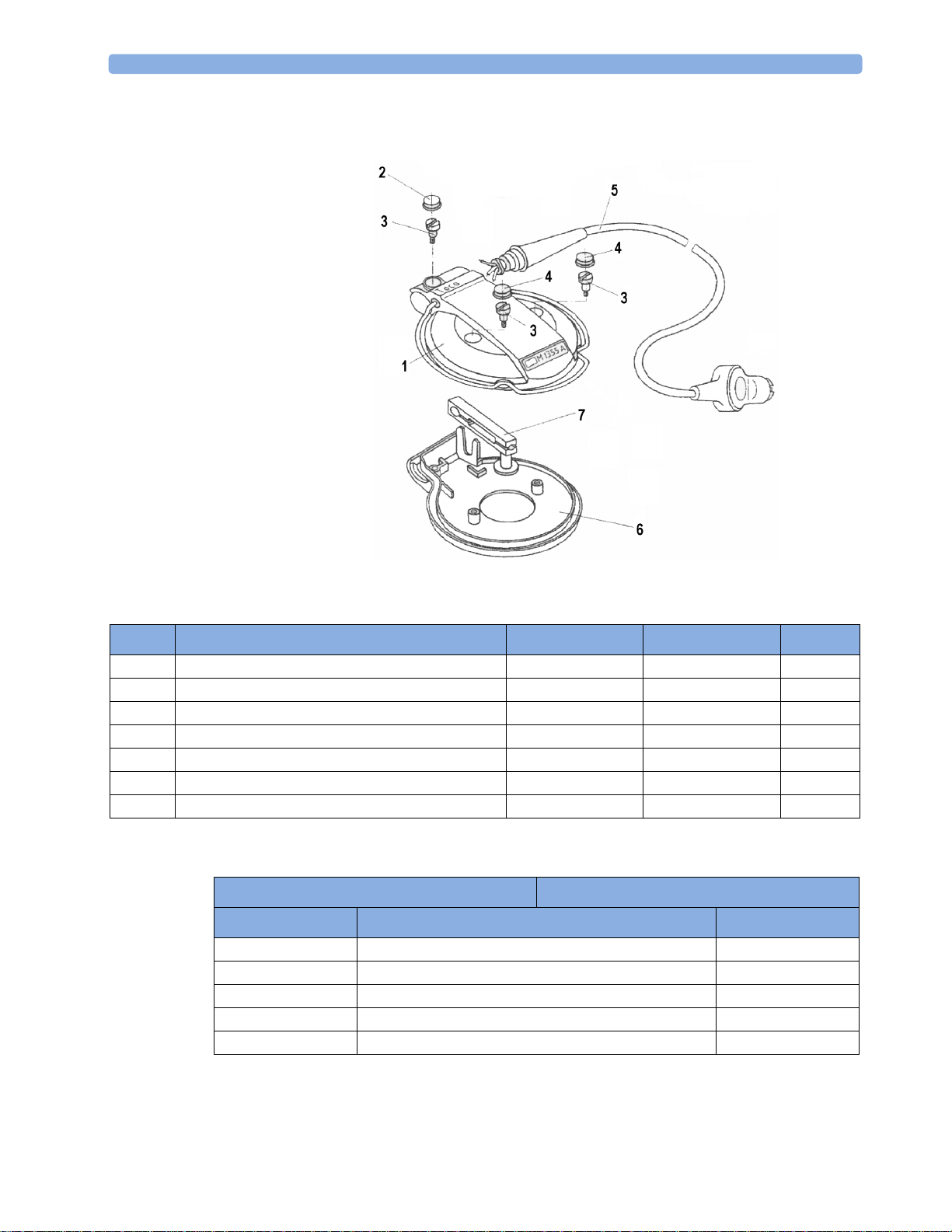
Parts for the Toco Transducer
Toco Transducer: Parts List
Item Description
1 Case Top (Toco, Brown) M1355-44552 453563277111 1
2 Cover Screw (Brown) M1355-44105 453563277091 1
3 Screw 0515-2121 453563024231 3
4 Cover Screw (Black) 5041-4274 453563099961 2
5 Cable Assembly (Toco) 2.5m / 8.2ft M1355-61652 453563277161 1
6 Case Bottom (Toco, Brown) M1355-44551 453563277101 1
7 Strain Gauge 0960-0810 453563045191 1
Toco Transducer: Cable Connections
Part Number 12NC
Connector Transducer
Pin Cable Color Pin
2Yellow2
3 Green 4
4Blue1
8Orange3
1+6 Bridged by Code Resistor 4.53 k
Ω -
Quantity
4
 Loading...