


Philips 27PT9015D Connection Guide
Component Video
Input
Provides superior picture
quality by separating the
green, blue and red
luminance signals. Typically
used with red/white
audio cables.
Better Good
Basic Basic
RF
Provides a basic
connection
for antenna or cable.
Provides both audio
and video.
Connection Basics
Composite Audio/Video
Separate video (yellow) and
audio (red/white) cables that
provide a basic connection from
the cable box and other devices.
Note : The color of audio inputs
may differ, e.g. red/white or
red/black.
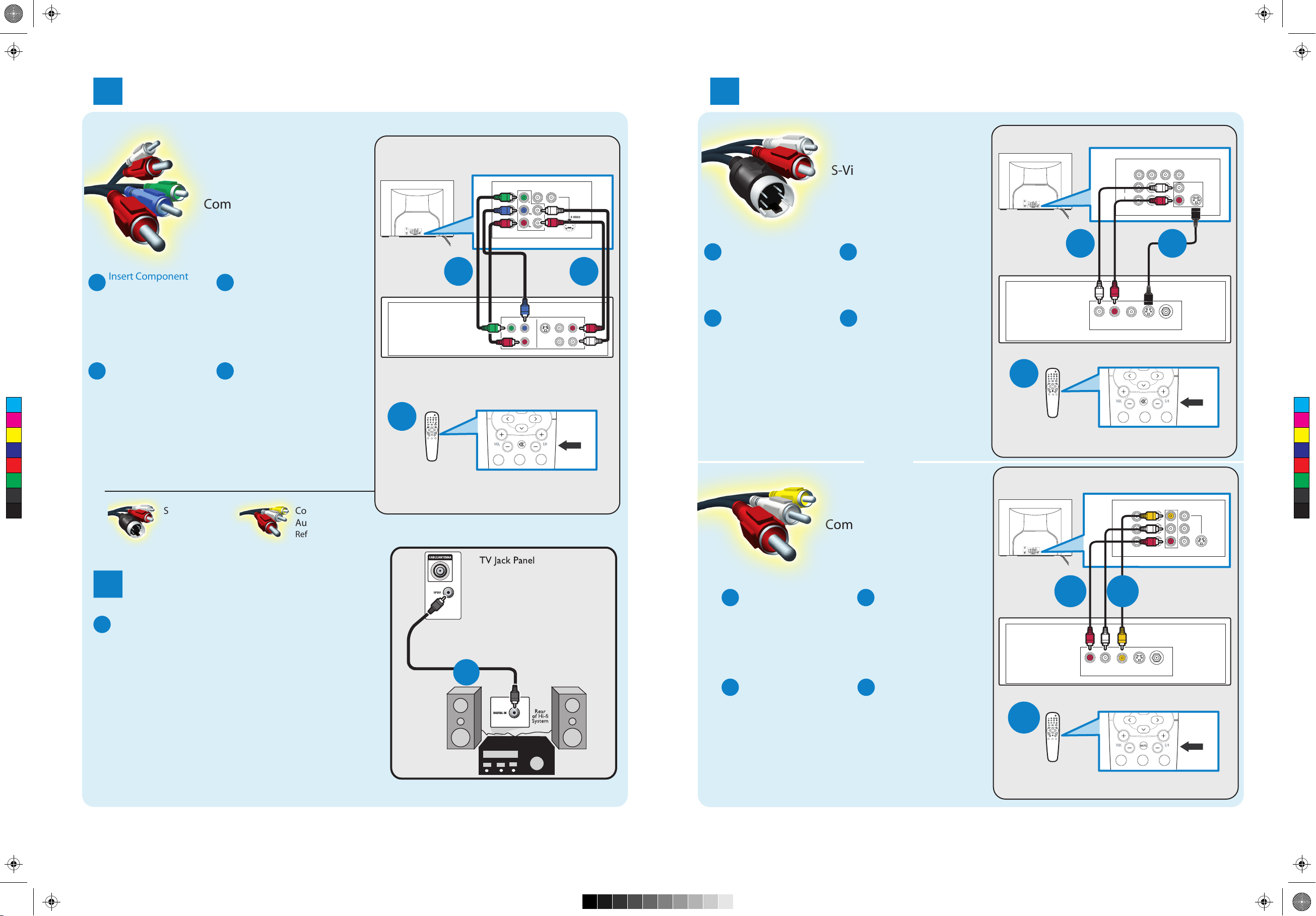
S-Video
Supplies a better picture
than RF and Composite
connections. Used with
red/white audio cables.
1
Set-Top Box to TV
Other Possible
Connections
Component
Video
Refer to panel 4.
5
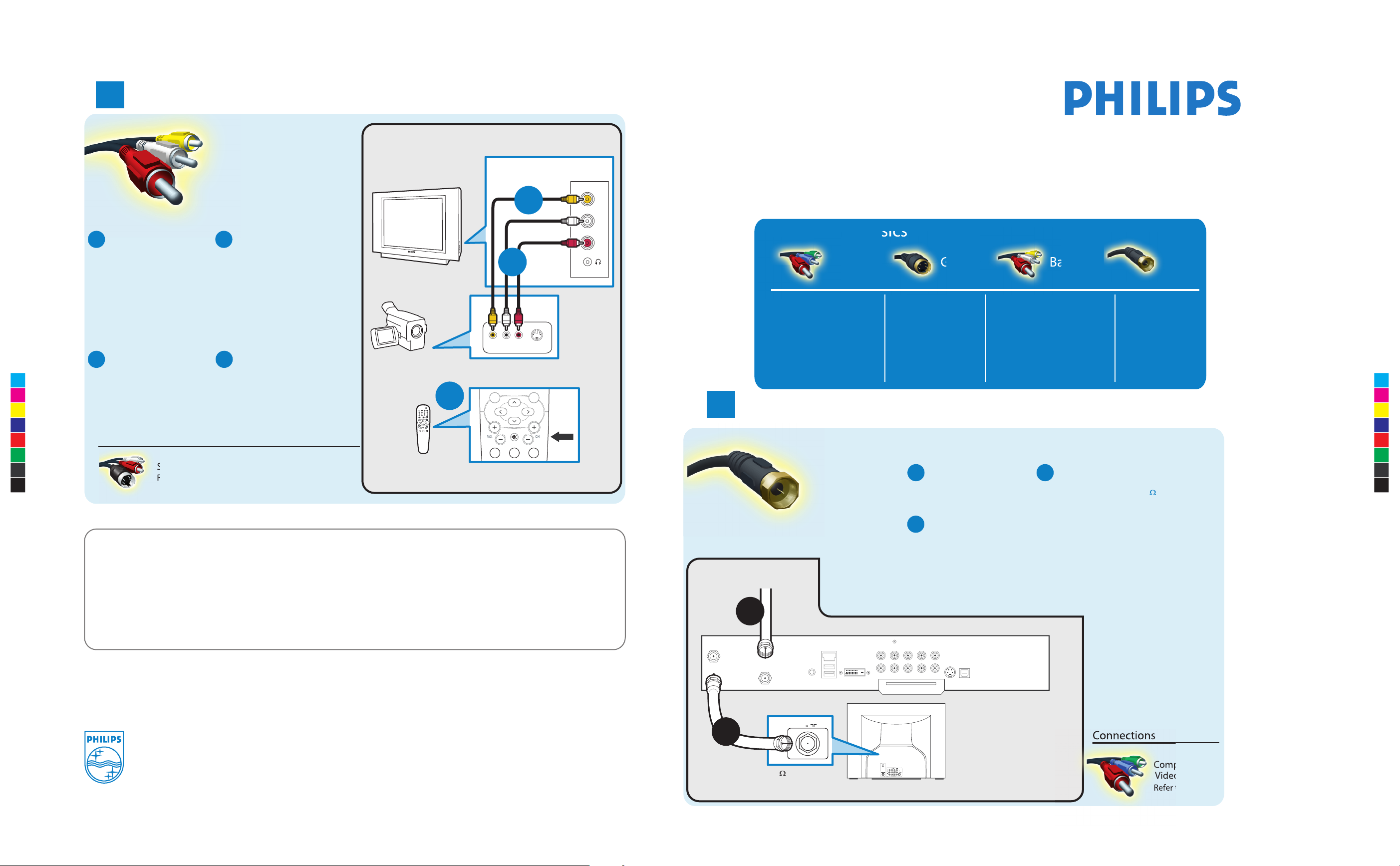
Video Camera/Games Console to TV
Composite Audio/Video
Other Possible Connections
Note: for mono devices,
connect only white audio
cable from device’s audio
output to white audio input
on the side of TV.
Connect audio cables
(red/white) from audio
outputs on device to
audio inputs (red/white)
on the side of TV.
B
A
Connect the video
cable (yellow) from
the video output on
camera (or other
device) to the video
input (yellow)
located on the side
of TV.
Press PLAY on the
device to verify
connection.
DC
Turn on TV and the
device. Press CH+ or
CH- on the remote
control until FRONT/
SIDE appears on TV
screen.
S-Video
Refer to panel 4.
VIDEO
AUDIO
L
R
S-VIDEO
VIDEO
AUDIO
LEFT RIGHT
CH+ and CH- Buttons
Remote
Control
Video Camera
TV
TV Side Jack Panel
Video Camera Jack Panel
How to
make the best connection
Use this guide to achieve the optimal connection for each of your components.
Alternative connections are also provided.
RF Cable
C
A
B
C
2005 © Koninklijke Philips Electronics N.V.
All rights reserved.
3139 125 35351
Need more help?
User manual:
Check the user manual that came with your TV.
Online help: www.p4c.philips.com or
www.usasupport.philips.com
Back of Cable Box
Cable Signal IN
from Cable Company
TO
TV/VCR
CABLE
IN
IR
USB
DVD-D OUT
AUDIO IN
SPDIF
VIDEO
IN OUT
S-VIDEO
R L
AUDIO OUT
TV
PASSCARD
Y Pb Pr
OPTICAL
SPDIF
TV
75 Input
75
A
B
-
A
Connect RF cable
from wall to input at
the back of the cable
box.
C
Set output switch
on set-top box to
CH 3 or 4 and tune
TV to same channel.
Use second RF cable to
connect the cable box
to the TV input (75 ).
B
Note: This connection gives
mono sound. For stereo
sound use also composite
audio/video connection
(Refer to panel 4).
C
M
Y
CM
MY
CY
CMY
K
HUG_30PW9110D.pdf 2005-06-30 11:00:00 AMHUG_30PW9110D.pdf 2005-06-30 11:00:00 AM
OK
MENU
MUTE
123
1
2
3
Monitor out
Pages from BestConnGuide_LO6ATSC_Eng_23Aug_p2.pdf 2005-08-23 5:30:32 PMPages from BestConnGuide_LO6ATSC_Eng_23Aug_p2.pdf 2005-08-23 5:30:32 PM
DVD Player or DVD Recorder to TV
2
VCR to TV
4
TV Jack Panel
AV1 in
Y
Pb
Pr
T VIDEO INPUT
AV2 in
S-VIDEO
Component Video Input
TV Jack Panel
Monitor out
VIDEO
L/Mono
Monitor out
AUDIO
VIDEO
L/Mono
R
COMPONEN
S-Video
AV2 in
AV1 in
Monitor out
TV
Monitor out
TV
Insert Component
A
Video connectors into
their corresponding
jacks on both DVD
player/DVD recorder
and TV (sometimes
labeled Y, Pb and Pr).
Turn on TV and DVD
C
player/DVD recorder.
Press CH+ or CH-
C
M
Y
CM
MY
CY
CMY
K
on remote control
until CVI appears on
TV screen
.
Other Possible Connections
S-Video Composite
Refer to panel 4.
Connect red/white
B
audio cables into the
audio output jacks
on DVD player/DVD
recorder and audio
AV inputs on TV.
Insert a pre-recorded
D
DVD into DVD player/
DVD recorder and
press PLAY to verify
correct connection.
Note: When using CVI, it is best
not to connect a video signal to
the other AV input on the TV.
Audio/Video
Refer to panel 4.
Back of
C
DVD Player/Recorder
Remote
Control
A
2
3
1
CH+ and CH- Buttons
R
COMPONEN
T VIDEO INPUT
COM
P VIDEO
Y
Pb
Pr
MUTE
1 2 3
S-VIDEO
S-VIDEO
A
ANT/CABLE
OUT
OUT
Connect S-Video
A
cable to S-Video input
B
on back of TV and
S-Video output on
back of VCR
AUDIO
VIDEO
R
OUT
OUT
OUT
L
Turn on TV and VCR.
C
Press CH+ or CH- on
remote control until
S-Video appears
on TV screen
.
.
Connect audio cables
B
(red/white) to audio AV
inputs on back of TV and
Audio outputs on back
of VCR.
Insert pre-recorded
D
videotape into VCR and
press PLAY to verify
correct connection.
Back of
VCR
B
L R
AUDIO OUT
VIDEO
OUT
C
Note: When you connect S-Video and AV2 at the same time,
you can only hear sound coming from AV2.
S-Video will dominate over the Video of AV2.
OR
Composite Audio/Video
Remote
Control
Monitor out
3
2
1
CH+ and CH- Buttons
MUTE
1 2 3
CH+ and CH- Buttons
TV Jack Panel
A
V1 in
T VIDEO INPUT
AV2 in
S-VIDEO
AUDIO
L/Mono
Monitor out
VIDEO
R
COMPONEN
TV
Audio to Hi-fi System
3
Connect audio cable from the SPDIF jack on the
A
rear of the TV to the DIGITAL IN jack on the
rear of the hi-fi system.
Note : SPDIF (Sony and Philips Digital Interconnect Format)
is highly recommended for high quality digital sound
output.
A
Connect the video
A
cable (yellow) to the
VIDEO AV input on
back of TV and the
corresponding video
output on back
of VCR
Turn on the TV and
C
VCR. Press CH+ or
.
CH- on remote
control until AV1 or
AV2 appears on TV
screen
.
Connect audio cables
B
(red/white) to audio
AV inputs on back of
TV and the corre
-
sponding audio
Back of
VCR
B
A
outputs (L & R) on
back of VCR.
Insert pre-recorded
D
videotape into VCR
and press PLAY to
verify correct con
-
nection.
C
1
3
2
Remote
Cont
rol
R L
AUDIO OUT
S-VIDEO
VIDEO
ANT/CABLE
OUT
OUT
1 2 3
OUT
CH+ and CH- Buttons