


IMPORTANT SAFETY NOTICE
Proper service and repair is important to the safe, reliable operation of all Philips
Consumer Electronics Company** Equipment. The service procedures recommended by
Philips and described in this service manual are effective methods of performing service
operations. Some of these service operations require the use of tools specially designed
for the purpose. The special tools should be used when and as recommended.
It is important to note that this manual contains various CAUTIONS and NOTICES
which should be carefully read in order to minimize the risk of personal injury to service
personnel. The possibility exists that improper service methods may damage the
equipment. It also is important to understand that these CAUTIONS and NOTICES
ARE NOT EXHAUSTIVE. Philips could not possibly know, evaluate and advise the
service trade of all conceivable ways in which service might be done, or of the possible
hazardous consequences of each way. Consequently, Philips has not undertaken any such
broad evaluation. Accordingly, a servicer who uses a service procedure or tool which is
not recommended by Philips must first satisfy himself thoroughly that neither his safety
nor the safe operation of the equipment will be jeopardized by the service method
selected.
** Hereafter throughout this manual, Philips Consumer Electronics Company will be
referred to as Philips.
WARNING
Critical components having special safety characteristics are identified with a or
"S" by the Ref. No. in the parts list and enclosed within a broken line* (where
several critical components are grouped in one area) along with the safety symbol
on the schematics or exploded views. Use of substitute replacement parts which
do not have the same specified safety characteristics may create shock, fire, or other
hazards. Under no circumstances should the original design be modified or altered
without written permission from Philips. Philips assumes no liability, express or
implied, arising out of any unauthorized modification of design. Servicer assumes all
liability.
* Broken Line ____ _ ____ _ ____ _ ____

FIRE AND SHOCK HAZARD
1. Be sure all components are positioned in such a way as to avoid the possibility of adjacent component
shorts. This is especially important on those chassis which are transported to and from the service shop.
2. Never release a repaired unit unless all protective devices such as insulators, barriers, covers, strain
reliefs, and other hardware have been installed in accordance with the original design.
3. Soldering and wiring must be inspected to locate possible cold solder joints, solder splashes, sharp solder
points, frayed leads, pinched leads, or damaged insulation (including the ac cord). Be certain to remove
loose solder balls and all other loose foreign particles.
4. Check across-the-line components and other components for physical evidence of damage or
deterioration and replace if necessary. Follow original layout, lead length, and dress.
5. No lead or component should touch a receiving tube or a resistor rated at 1 watt or more. Lead tension
around protruding metal surfaces or edges must be avoided.
6. Critical components having special safety characteristics are identified with an 'S' by the Ref. No. in the
parts list and enclosed within a broken line* (where several critical components are grouped in one area)
along with the safety symbol on the schematic diagrams and /or exploded views.
7. When servicing any unit, always use a separate isolation transformer for the chassis. Failure to use a
separate isolation transformer may expose you to possible shock hazard, and may cause damage to
servicing instruments.
8. Many electronic products use a polarized ac line cord (one wide pin on the plug). Defeating this safety
feature may create a potential hazard to the servicer and the user. Extension cords which do not
incorporate the polarizing feature should never be used.
9. After reassembly of the unit, always perform an ac leakage test or resistance test from the line cord to all
exposed metal parts of the cabinet. Also, check all metal control shafts (with knobs removed), antenna
terminals, handles, screws, etc., to be sure the unit may be safely operated without danger of electrical
shock.
* Broken line ____ _ ____ _ ____ _ ____

LEAKAGE CURRENT COLD CHECK
1. Unplug the ac line cord and connect a jumper between the two prongs of the plug.
2. Turn on the power switch.
3. Measure the resistance value between the jumpered ac plug and all exposed cabinet parts of the receiver,
such as screw heads, antennas, and control shafts. When the exposed metallic part has a return path to the
chassis, the reading should be between 1 megohm and 5.2 megohms. When the exposed metal does not
have a return path to the chassis, the reading must be infinity. Remove the jumper from the ac line cord.
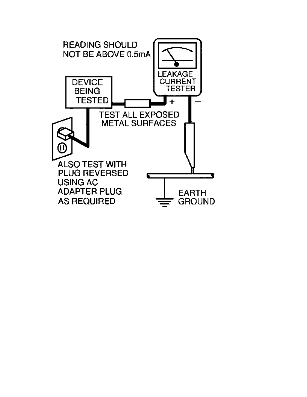
LEAKAGE CURRENT HOT CHECK
1. Do not use an isolation transformer for this test. Plug the completely reassembled receiver directly into
the ac outlet.
2. Connect a 1.5k, 10W resistor paralleled by a 0.15uF. capacitor between each exposed metallic cabinet
part and a good earth ground such as a water pipe, as shown below.
3. Use an ac voltmeter with at least 5000 ohms/volt sensitivity to measure the potential across the resistor.
4. The potential at any point should not exceed 0.75 volts. A leakage current tester may be used to make
this test; leakage current must not exceed 0.5mA. If a measurement is outside of the specified limits,
there is a possibility of shock hazard. The receiver should be repaired and rechecked before returning it
to the customer.
5. Repeat the above procedure with the ac plug reversed. (Note: An ac adapter is necessary when a
polarized plug is used. Do not defeat the polarizing feature of the plug.)
OR
With the instrument completely reassembled, plug the ac line cord directly into a 120Vac outlet. (Do not
use an isolation transformer during this test.) Use a leakage current tester or a metering system that
complies with American National Standards Institute (ANSI) C101.1 Leakage Current for Appliances and
Underwriters Laboratories (UL) 1410, (50.7). With the instrument ac switch first in the on position and
then in the off position, measure from a known earth ground (metal water pipe, conduit, etc.) to all exposed
metal parts of the instrument (antennas, handle brackets, metal cabinet, screw heads, metallic overlays,
control shafts, etc.), especially any exposed metal parts that offer an electrical return path to the chassis.
Any current measured must not exceed 0.5mA. Reverse the instrument power cord plug in the outlet and
repeat the test. See the graphic below.

TV SAFETY NOTES
SAFETY CHECKS
After the original service problem has been corrected, a complete safety check should be made. Be sure to
check over the entire set, not just the areas where you have worked. Some previous servicer may have left
an unsafe condition, which could be unknowingly passed on to your customer. Be sure to check all of the
following:
Fire and Shock Hazard
Implosion
X-Radiation
Leakage Current Cold Check
Leakage Current Hot Check
Picture Tube Replacement
Parts Replacement
WARNING: Before removing the CRT anode cap, turn the unit OFF and short the HIGH VOLTAGE to
the CRT DAG ground.
SERVICE NOTE: The CRT DAG is not at chassis ground.
IMPLOSION
1. All picture tubes used in current model receivers are equipped with an integral implosion system.
Care should always be used, and safety glasses worn, whenever handling any picture tube. Avoid
scratching or otherwise damaging the picture tube during installation.
2. Use only replacement tubes specified by the manufacturer.
X-RADIATION
1. Be sure procedures and instructions to all your service personnel cover the subject of X-radiation.
Potential sources of X-rays in TV receivers are the picture tube and the high voltage circuits. The
basic precaution which must be exercised is to keep the high voltage at the factory recommended
level.
2. To avoid possible exposure to X-radiation and electrical shock, only the manufacturer's specified
anode connectors must be used.
3. It is essential that the service technician has an accurate HV meter available at all times. The
calibration of this meter should be checked periodically against a reference standard.
4. When the HV circuitry is operating properly there is no possibility of an X-radiation problem. High
voltage should always be kept at the manufacturer's rated value - no higher - for optimum
performance. Every time a color set is serviced, the brightness should be run up and down while
monitoring the HV with a meter to be certain that the HV is regulated correctly and does not exceed
the specified value. We suggest that you and your technicians review test procedures so that HV and
HV regulation are always checked as a standard servicing procedure, and the reason for this prudent
routine is clearly understood by everyone. It is important to use an accurate and reliable HV meter. It
is recommended that the HV reading be recorded on each customer's invoice, which will
demonstrate a proper concern for the customer's safety.

5. When troubleshooting and making test measurements in a receiver with a problem of excessive high
voltage, reduce the line voltage by means of a Variac to bring the HV into acceptable limits while
troubleshooting. Do not operate the chassis longer than necessary to locate the cause of the excessive
HV.
6. New picture tubes are specifically designed to withstand higher operating voltages without creating
undesirable X-radiation. It is strongly recommended that any shop test fixture which is to be used
with the new higher voltage chassis be equipped with one of the new type tubes designed for this
service. Addition of a permanently connected HV meter to the shop test fixture is advisable. The
CRT types used in these new sets should never be replaced with any other types, as this may result in
excessive X-radiation.
7. It is essential to use the specified picture tube to avoid a possible X-radiation problem.
8. Most TV receivers contain some type of emergency "Hold Down" circuit to prevent HV from rising
to excessive levels in the presence of a failure mode. These various circuits should be understood by
all technicians servicing them, especially since many hold down circuits are inoperative as long as
the receiver performs normally.
PICTURE TUBE REPLACEMENT
The primary source of X-radiation in this television receiver is the picture tube. The picture tube
utilized in this chassis is specially constructed to limit X-radiation emissions. For continued Xradiation protection, the replacement tube must be the same type as the original, including suffix letter,
or a Philips approved type.
PARTS REPLACEMENT
Many electrical and mechanical parts in Philips television sets have special safety related
characteristics. These characteristics are often not evident from visual inspection nor can the protection
afforded by them necessarily be obtained by using replacement components rated for higher voltage,
wattage, etc. The use of a substitute part which does not have the same safety characteristics as the
Philips recommended replacement part shown in this service manual may create shock, fire, or other
hazards.
PRODUCT SAFETY GUIDELINES FOR ALL PRODUCTS
CAUTION: Do not modify any circuit. Service work should be performed only after you are thoroughly
familiar with all of the following safety checks. Risk of potential hazards and injury to the user increases if
safety checks are not adhered to.
USE A SEPARATE ISOLATION TRANSFORMER FOR THIS UNIT WHEN SERVICING.

PREVENTION OF ELECTROSTATIC DISCHARGE (ESD)
Some semiconductor solid state devices can be damaged easily by static electricity. Such components
commonly are called Electrostatically Sensitive (ES) Devices, Examples of typical ES devices are
integrated circuits and some field-effect transistors and semiconductor "chip" components. The following
techniques should be used to help reduce the incidence of component damage caused by electrostatic
discharge (ESD).
1. Immediately before handling any semiconductor component or semiconductor-equipped assembly, drain
off any ESD on your body by touching a known earth ground. Alternatively, obtain and wear a
commercially available discharging ESD wrist strap, which should be removed for potential shock
reasons prior to applying power to the unit under test.
2. After removing an electrical assembly equipped with ES devices, place the assembly on a conductive
surface such as aluminum foil, to prevent electrostatic charge buildup or exposure of the assembly.
3. Use only a grounded-tip soldering iron to solder or unsolder ES devices.
4. Use only an anti-static solder removal device. Some solder removal devices not classified as "antistatic
(ESD protected)" can generate an electrical charge sufficient to damage ES devices.
5. Do not use Freon propelled chemicals. These can generate electrical charges sufficient to damage ES
devices.
6. Do not remove a replacement ES device from its protective package until immediately before you are
ready to install it (most replacement ES devices are packaged with leads electrically shorted together by
conductive foam, aluminum foil or comparable conductive material).
7. Immediately before removing the protective material from the leads of a replacement ES device, touch
the protective material to the chassis or circuit assembly into which the device will be installed.
CAUTION: Be sure no power is applied to the chassis or circuit and observe all other safety precautions.
8. Minimize bodily motions when handling unpackaged replacement ES devices. (Otherwise harmless
motion such as the brushing together of your clothes fabric or the lifting of your feet from a carpeted
floor can generate static electricity (ESD) sufficient to damage an ES device.)
NOTE to CATV system Installer:
This reminder is provided to call the CATV system installer's attention to article 820-22 of the NEC that
provides guidelines for proper grounding and, in particular, specifies that the cable ground shall be
connected to the grounding system of the building, as close to the point of cable entry as practical.

PRACTICAL SERVICE PRECAUTIONS
IT MAKES SENSE TO AVOID EXPOSURE TO ELECTRICAL SHOCK. While some sources are
expected to have a possible dangerous impact, others of quite high potential are of limited current and are
sometimes held in less regard.
ALWAYS RESPECT VOLTAGES. While some may not be dangerous in themselves, they can cause
unexpected reactions – reactions that are best avoided. Before reaching into the powered color TV set, it is
best to test the high voltage insulation. It is easy to do, and is just a good service precaution.
BEFORE POWERING UP THE TV WITH THE BACK OFF (or on a test fixture), attach a clip lead to
the CRT DAG ground and to a screwdriver blade that has a well insulated handle. After the TV is powered
on and high voltage has developed, probe the anode lead with the blade, starting at the bottom of the High
Voltage Transformer (flyback – IFT). Move the blade to within two inches of the connector of the CRT. IF
THERE IS AN ARC, YOU FOUND IT THE EASY WAY, WITHOUT GETTING A SHOCK! If
there is an arc to the screwdriver blade, replace the High Voltage Transformer or the lead, (if removable)
whichever is causing the problem.
PICTURE TUBE REPLACEMENT PROCEDURE
Note: a. Two (2) people are required to handle this picture tube.
b. Safety Glasses must be worn during this procedure or whenever directly handling a picture tube.
c. Take care in each step not to damage the CRT or the cabinet.
1. Remove the Chassis and the CRT Socket Board Module from the cabinet.
2. A furniture pad or blanket should be positioned on the floor to support only the CRT Face. This pad or
blanket should be high enough to keep the CRT Face approximately 12 to 14 inches off the floor.
3. Using two people, place the cabinet in a front down position with the CRT Face on the pad or blanket.
4. Place padded blocks under each corner of the cabinet to keep it from rocking.
5. Remove the four screws, at the corners of the CRT.
6. With two people lowering the cabinet to the floor, leave the CRT elevated by the pad or blanket.
Note: Take care not to grasp the neck of the CRT during this procedure, as it is extremely fragile.
7. Two (2) people may then lift the CRT from the cabinet.
8. Remove the degaussing coil from the defective CRT and mount on the replacement. Take care to
maintain the exact shape and fit.
To install the new CRT, reverse steps 1 to 7.

GENERAL INFORMATION Typical Models
Standard Screen - Model: 27PT71
Flat Screen - Model: 27PT91

Technical Specifications
Supply
Supply Voltage : 90 – 140Vac
Power Consumption : 90 W max.
Stand By consumption : 7 – 8W
Supply Frequency : 50 - 60 Hz ? 5 %
Tuning System : PLL
Reception : NTSC-M
Sound System : BTSC DBX
Sound Output : 2 x 5 W – 27”/32”/36” FSQ
: 2 x 5 W + 10W – 27” /32” RF
Reception : Off air - 45.75Mhz
Aerial input : coaxial 75 Ohm
Remote Control : Type - RCA10U81 - 27”/32”/36” FSQ
: Type - RCA10U20 - 27”/32” RF
Connection Facilities
EXT1: CVBS (in) + YUV (in)
Cinch - CVBS (yellow) (1 V)
Cinch - Audio L (red) (0.2 - 2 V-RMS / 10 k ohm)
- Audio R (white) (0.2 - 2 V-RMS / 10 k ohm)
EXT2: CVBS (in) + YC (in)
Cinch CVBS (yellow) (1 V)
Cinch Audio L (red) (0.2 - 2 V-RMS / 10 k ohm)
Audio R (white) (0.2 - 2 V-RMS / 10 k ohm)

MON: CVBS (out) + L/R (out)
Cinch CVBS (yellow) (1 V)
Cinch Audio L (red) (0.2 - 2 V-RMS / 10 k ohm)
Audio R (white) (0.2 - 2 V-RMS / 10 k ohm)
YUV (in)
Cinch Y (0.7Vpp/ 75 ohm)
Cinch U (0.7Vpp/ 75 ohm)
Cinch V (0.7Vpp / 75 ohm)
Cinch Front - audio/video in
Cinch CVBS (yellow) 1(1 V)
Cinch Audio L (red) (0.2 - 2 V-RMS / 10 k ohm)
Audio R (white) (0.2 - 2 V-RMS / 10 k ohm)
Headphone
Jack 32 - 2000 ohm (10 mW)
SVHS
1 - gnd
2 - gnd
3 – Y (1 V-PP / 75 ohm)
4 – C (0.3 V-PP / 75 ohm)

CBA Location Guide

Model to Module Listings
MODEL PANEL
27PT31B/121
313917867841 Large Signal Panel
313917883531 Small Signal Panel
313917880521 M-Link Assembly (W/O M-Link)
AVJ400A/001 Side Jack Panel
27PT41B/121
313917867851 Large Signal Panel
313917865621 Small Signal Panel
AVJ400A/001 Side Jack Panel
A10902A/001 M-Link Assembly
A10904A/001 PIP Panel
27PT71B/121
EMH802A/001 Large Signal Panel
313917863191 Small Signal Panel
AVJ400A/001 Side Jack Panel
A10902A/001 M-Link Assembly
A10901A/001 PIP Panel
310420710191 Receiver Assembly IR Board
27PT81S/125
313917888281 Large Signal Panel
313917863191 Small Signal Panel
313917867911 Side Jack Panel
313917860611 M-Link Assembly (With Matrix)
313917882271 Top Control Assembly
313917865661 Front Interface Assembly
313917859401 PIP Panel (2 Tuner)
310420710191 Receiver Assembly IR Board
27PT91S/125
313917867901 Large Signal Panel
313917865601 Small Signal Panel
313917882271 Top Control Assembly
313917867911 Side Jack Panel
A10902A/001 M-Link Assembly
313917865661 Front Interface Panel
312123751431 Double Window PIP Assembly
313917863791 * Guide Plus Panel
313917857061 * Double Window PIP Panel
* These panels are subassemblies of the Double Window PIP assembly.

32PT41B/121
313917868651 Large Signal Panel
313917865621 Small Signal Panel
AVJ400A/001 Side Jack Panel
A10902A/001 M-Link Assembly
A10904A/001 PIP Panel
32PT71B/121
313917867861 Large Signal Panel
313917863191 Small Signal Panel
AVJ400A/001 Side Jack Panel
A10902A/001 M-Link Assembly
A10901A/001 PIP Panel
310420710191 Receiver Assembly IR Board
32PT81S/128
313917888271 Large Signal Panel
313917863191 Small Signal Panel
313917867911 Side Jack Panel
313917860611 M-Link Assembly (With Matrix)
313917882271 Top Control Assembly
313917865661 Front Interface Panel
313917859401 PIP Panel
310420710191 Receiver Assembly IR Board
32PT91B/128
313917865591 Large Signal Panel
313917865601 Small Signal Panel
312123751431 Double Window PIP Assembly
313917857061 * Double Window PIP Panel
313917863791 * Guide Plus Panel
A10901A/001 PIP Panel (2 Tuner)
A10902A/001 M-Link Assembly
A10904A/001 PIP Panel
313917865661 Front Interface Panel
313917864271 Top Control Assembly
313917867911 Side Jack Panel
* These panels are subassemblies of the Double Window PIP assembly.

32PT91S/121
313917865591 Large Signal Panel
313917865601 Small Signal Panel
A10901A/001 PIP Panel (2 Tuner)
A10902A/001 M-Link Assembly
A10904A/001 PIP Panel
313917865661 Front Interface Panel
313917864271 Top Control Assembly
313917867911 Side Jack Panel
310420710191 Receiver Assembly IR Board
312123751431 Double Window PIP Assembly
313917857061 * Double Window PIP Panel
313917863791 * Guide Plus Panel
* These panels are subassemblies of the Double Window PIP assembly.
36PT41B/129
EMH860A/001 Large Signal Panel
313917865621 Small Signal Panel
AVJ400A/001 Side Jack Panel
A10902A/001 M-Link Assembly
A10904A/001 PIP Panel
310420710191 Receiver Assembly IR Board
36PT71B/129
313917867871 Large Signal Panel
313917863191 Small Signal Panel
AVJ400A/001 Side Jack Panel
A10902A/001 M-Link Assembly
A10901A/001 PIP Panel
310420710191 Receiver Assembly IR Board
29LP602/221
EMH802A/001 Large Signal Panel
313917863191 Small Signal Panel
310420710191 Receiver Assembly IR Board
AVJ400A/001 Side Jack Panel
A10902A/001 M-Link Assembly
A10901A/001 PIP Panel (2 Tuner)
32PT71B/129
313917885031 Large Signal Panel
313917863191 Small Signal Panel
AVJ400A/001 Side Jack Panel
A10902A/001 M-Link Assembly
A10901A/001 PIP Panel (2 Tuner)
310420710191 Receiver Assembly IR Board

33LP803/221
313917867861 Large Signal Panel
313917863191 Small Signal Panel
AVJ400A/001 Side Jack Panel
A10902A/001 M-Link Assembly
A10901A/001 PIP Panel (2 Tuner)
310420710191 Receiver Assembly IR Board
Model To Remote Transmitter Listing
Model Part Ref. Part No. Transmitter Type
27PT91S/125 AC19 3128 147 12101 RC2037/01 Remote Transmitter
32PT91S/121 AC19 3129 147 12101 RC2037/01 Remote Transmitter
27PT41B/121 AC19 3139 128 75961 RCA10U81E Remote Transmitter
32PT41B/121 AC19 3140 128 75961 RCA10U81E Remote Transmitter
36PT41B/129 AC19 3141 128 75961 RCA10U81E Remote Transmitter
27PT71B/121 AC19 3139 128 75991 RCA10U81FX Remote Transmitter
27PT81S/125 AC19 3140 128 75991 RCA10U81FX Remote Transmitter
29LP602/221 AC19 3141 128 75991 RCA10U81FX Remote Transmitter
32PT71B/121 AC19 3142 128 75991 RCA10U81FX Remote Transmitter
32PT71B/129 AC19 3143 128 75991 RCA10U81FX Remote Transmitter
32PT81S/128 AC19 3144 128 75991 RCA10U81FX Remote Transmitter
33LP803/221 AC19 3145 128 75991 RCA10U81FX Remote Transmitter
36PT71B/129 AC19 3146 128 75991 RCA10U81FX Remote Transmitter
27PT31B/121 AC19 3139 128 76001 RCA10U81BX/01 Remote Transmitter


Mechanical Disassembly
Rear Cover Removal & Replacement
Removal of the Rear Cover
1. Remove all screws from the rear cover.
2. Remove the rear cover.
Replacement of the Rear Cover
Before replacing the Rear Cover, perform the following inspection:
• Ensure that AC Cord is placed correctly in the guide brackets.
• Ensure that all cables are placed in their original position.
Service Positions
The following CBA's are present in this chassis (see also 'Chassis overview', CBA Location Diagram):
1. Large Signal Panel (LSP)
2. Small Signal Board (SSB)
3. Top Control panel
4. CRT panel (or PTP)
5. Side I/O panel
6. Mains Switch/LED panel
7. M-Link
8. PIP-panel
9. Guide+ panel
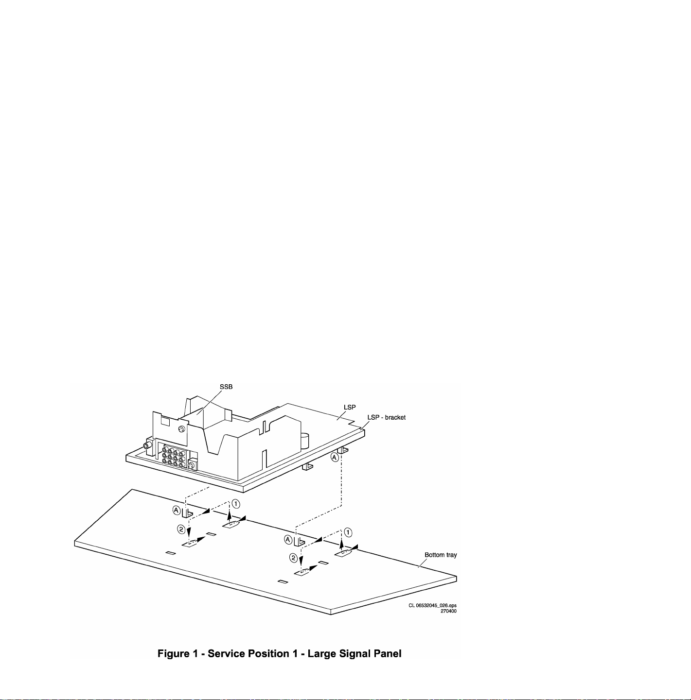
Service Position 1 for the Large Signal Panel (LSP)
Position 1: The following service position will provide the best accessibility to the Top Side of the Large Signal Panel:
1. Remove the LSP-bracket from the bottom tray by sliding the bracket backward and then pull the bracket up and out of the
bottom tray.
2. Place the Hooks (A) of the bracket in the first row of fixation holes of the cabinet bottom. In other words reposition the
bracket hooks from position (1) to position (2).
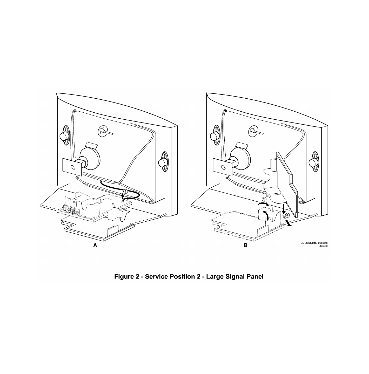
Service Position 2 for the Large Signal Panel (LSP)
Position 2: The following service position will provide the best accessibility to the bottom side (solder side) of the Large Signal
Panel:
1. Disconnect the degaussing coil from the LSP by removing the cable from connector 0211 (1).
2. Release the wiring from their clamps, to enable for repositioning the LSP.
3. Turn the chassis tray 90 degrees counter clockwise (2).
4. Flip the tray with the rear I/O panel toward the CRT (3).
5. Place the hook of the tray into the slot (4) at the right side of the cabinet bottom (4) and slide the chassis tray forward.

Service position for the Small Signal Board (SSB)
There is not a predefined service position for the bottom (B-) side of the SSB. All relevant test points can be accessed in both
LSB service positions.
If IC's must be replaced: take the complete panel out of the SIMM-connector.
1. Put the Large Signal Panel in service position 1 (as described above).
2. Release the 2 metal clamps at both sides of the SIMM-connector and the complete SSB can be taken out. It 'hinges' in the
SIMM-connector.
Access to the Top Control Panel
1. Remove the two screws that hold the panel to the cabinet back.
2. Slide the board backward (release it from the front hinge).
3. The board can easily be lifted out of the bracket after releasing the two clamps on the connector side.

Access to the Side I/O Panel
1. Remove the two screws.
2. Remove the complete Side I/O-assembly.
3. Release the two clamps then lift the board out of the bracket.
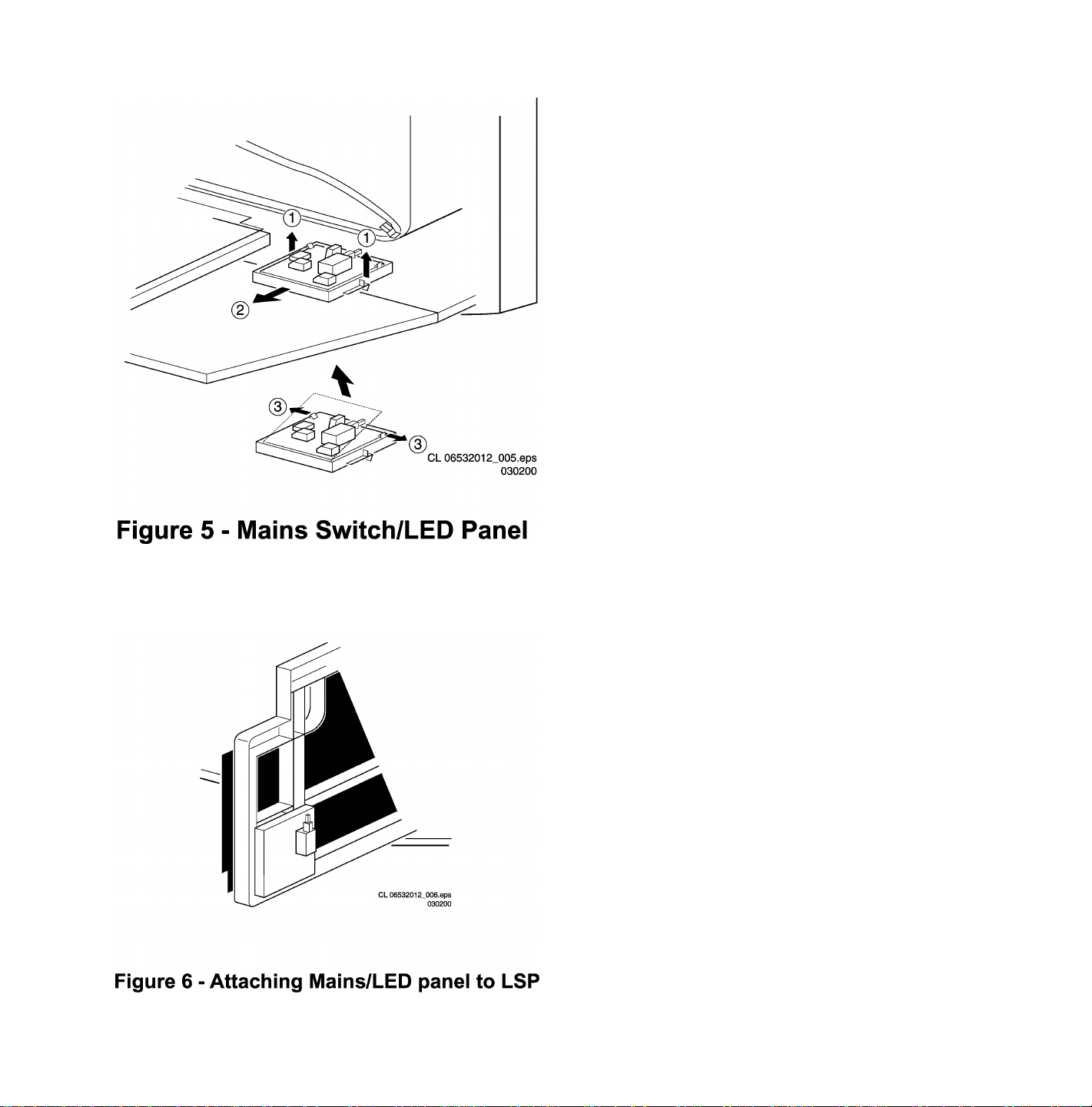
Access to the Mains Switch/LED Panel
1. Release the two clamps (1) by pulling them upward.
2. While pulling upward on the clamps, slide the complete assembly backward (2).
3. If it is necessary to remove the board, release the two clamps at the sides of the bracket and lift the board out (3).
1. To perform measurements, the panel may be attached to the LSP bracket (4).
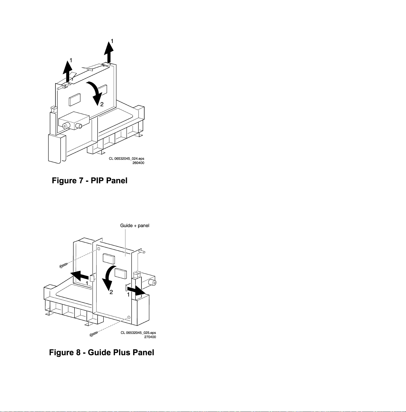
Access to the PIP Panel
1. Release the two clamps (1) and remove the PIP CBA from the bracket.
Access to the Guide+ Panel
1. Remove the two screws that secure the Guide+ assembly in place. This will release the complete Guide+ assembly.
2. Pull the two clamps (1) outward and remove the board (2) from the bracket.
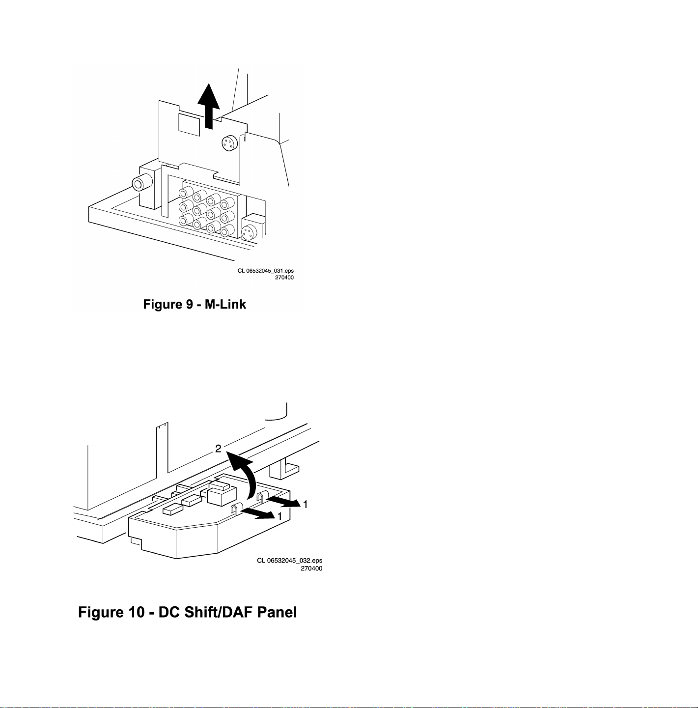
Access to the M-Link
1. Release the two clamps at both sides and remove the board from the bracket.
Access to the DC-shift/DAF panel
1. Release the clamps (1) and remove the board (2) from the bracket.

Troubleshooting Tips
Troubleshooting tips for the deflection and power supply circuitry.
The Deflection Circuit:
• Measure for VBAT (140V) across 2939/2940 (Section - A1 POWER SUPPLY). If the voltage is not present, disconnect
jumper 9936 and 9937 (see A1 Power Supply) The complete Line Deflection stage is now disconnected. If the voltage is
present then the deflection circuit may be the cause of the problem.
Possibilities include:
• Defective Transistor 7410
• Faulty driver circuit around transistor 7481
• No horizontal drive signal coming from the BOCMA (signal processor) IC 7301 pin 56 on the SSB
Note: If the Collector and Emitter of 7410 are shorted, a “hiccup” noise may be heard from the power supply circuit.
To determine whether the fault is present in the line deflection circuit (Section - A2 LINE DEFLECTION) or in the EW
circuit/panel (screen size above 21”), insert jumper into position numbers 9409 (in this case the EW protection is disabled). If
the basic deflection is working (picture is parabolic distorted), then the fault is located in the EW circuit/panel. If there is no
horizontal deflection, the fault is present in the basic deflection circuitry.
Also take note of protection circuits in the line output stage. If any of these circuits are activated, the set will shut down.
Depending upon protections, the LED will blink according to the fault defined. In order to determine which protection circuit is
active, isolation of circuits is necessary. These protection circuits are:
• High beam protection. See error 1 - High Beam Protection.
• X-ray protection : See error 1
If the high beam protection or the X-ray protection is active, it will switch the set to protection and the SDM will be automatically
activated. The service LED blinks repeatedly 1 time. If this happens, isolate each circuit to determine the cause
The Power Supply Circuit:
Trouble-shooting the H8 Switch Mode Power Supply (SMPS)
• First check the +5V_STBY voltage on IC 7968, pin 3/4.
• If this voltage is not present, check fuse 1961 and D6961.
• If there is not an open circuit at 1906 or D6917, the problem may be caused on the primary side of the switching supply.
Check the output of the bridge diodes on the cathode side of D6912/D6913 or D6915 - pin 1 for approximately 150V DC.
• If this voltage is not present, check the bridge diodes and the fuse.
• If fuse F1900 is open, check IC7921 (circuit A1) between pins 2 and 3 to insure that there is no short circuit present.
• If the 150V DC is present on pin 3 of IC7902, check for a startup voltage of 16V on pin 4 of IC7921.
• If the startup voltage is not present, check R3914 for an open circuit; a short circuit between pins 4 and 5 may also be the
cause of this problem.
• It is necessary to have a feedback signal from the hot secondary side of switch mode transformer T5912 at pin 8 and pin 9
for the power supply to oscillate.
• If this startup voltage is present on pin 4 of IC7902 and the supply is not oscillating, check R3929 and D6929.
• The H8 power supply has been designed with Over Voltage Protection (OVP).
• To determine whether OVP is active, check whether VBAT – 141V is present at IC7971 pin 1. If not, check the components
D6938, C2939 and C2940 and L5941.
• If these components are O.K., then check voltage at pin 3 of IC 7942.
• If this voltage is not present check fuse 1941 and fuse 1942. Replace if necessary.
• If dc-voltage is present at pin 3, replace opto-coupler 7929.
• Another way to confirm whether OVP is active is to measure the voltage with an oscilloscope at IC7902 pin 4. If the voltage
is fluctuating between 11-14V, then check the components described above.

Solving other problems
TV switched off or changes channel without any user action
Set switches off after “TV SWITCHING OFF” was displayed
Auto standby switched the set off because:
• there was no ident signal for more than 15 minutes
• there was no remote control signal received or local key pressed for > 2 hours
See Service Adjustments for a description of options to enable/disable auto standby.
Picture problems
Picture too dark or too bright
- Press “Smart Picture” button on the remote control. If this improves the picture, increase / decrease the brightness value or
increase / decrease the contrast value.
- Enter the Customer Service Mode. If this improves the picture, exit Customer Service Mode, then Increase / decrease the
brightness value or increase / decrease the contrast value.
White line around picture elements and text
- Press “Smart Picture” button on the remote control. If this improves the picture, decrease the sharpness value.
- Enter the Customer Service Mode. If this improves the picture. Decrease the sharpness value.
Snowy picture
- Snow is an antenna or antenna connector problem. Check tuner and AGC.
Black and white picture
- Press the “Smart Picture” button on the remote control. If this improves the picture, increase the color value.
- Enter the Customer Service Mode. If this improves the picture. Increase the color value.
Menu text not sharp enough
- Press the “Smart Picture” button on the remote control. If this improves the picture, decrease the contrast value.
- Enter the Customer Service Mode. If this improves the picture. Decrease the contrast value.
Sound problems
No sound or sound too loud (after channel change / switching on)
- Enter the Customer Service Mode. If the volume is OK. Increase / decrease the volume level.
H8 CHASSIS (A10) ADJUSTMENTS
Electrical Adjustments
Conditions
All electrical adjustments should be performed under the following conditions:
• Supply voltage: 120V +/- (10%)
• Warm-up time: 10 minutes
• The voltages and oscilloscope waveforms are measured in relation to the tuner ground.
• Test probe: Ri > 10Meg Ohm; Ci < 2.5 pF.
VG2 Adjustment
Rough alignment
Using a pattern generator displaying a circle pattern, adjust the VG2 potentiometer of LOT L5630 to obtain a normal picture.
Fine adjustment
1. Enter Service Alignment Mode (SAM) (see Software alignments (Service Alignment Mode)). Press the Cursor Down button
to Highlight the WHITE TONE menu item. Use the Cursor Right button to enter the WHITE TONE submenu. The NORMAL
RED submenu item appears.
- Use the Cursor Up/Down buttons to select NORMAL RED, NORMAL GREEN, and NORMAL BLUE submenu items.
- Using the Cursor Right button, increase the value of RED, GREEN and BLUE to 40
- Adjust the value of RED, GREEN and BLUE to 42 for 29” Models.
2. Press the MENU button to leave the SAM-menu and go to the customer menu. When the customer menu appears, the
PICTURE menu item is highlighted. Press Cursor Right button to enter the PICTURE submenu. Press the Cursor Down
button to highlight PICTURE submenu item. Press the Cursor Right/Left buttons to set register value to 0.
3. Press the MENU button to return to the main customer menu. Press MENU again to return to the SAM Main Menu. Press
the Cursor Down button to highlight the AKB menu item. Press Cursor Right button to turn AKB OFF.
4. Connect RF output of the pattern generator to input antenna. Test pattern: blank pattern (blank screen on CRT). Set the
time base of the oscilloscope to 0.5ms with external triggering of the vertical pulse. Measure the black level pulse during the
vertical flyback at the RGB cathodes of the CRT.
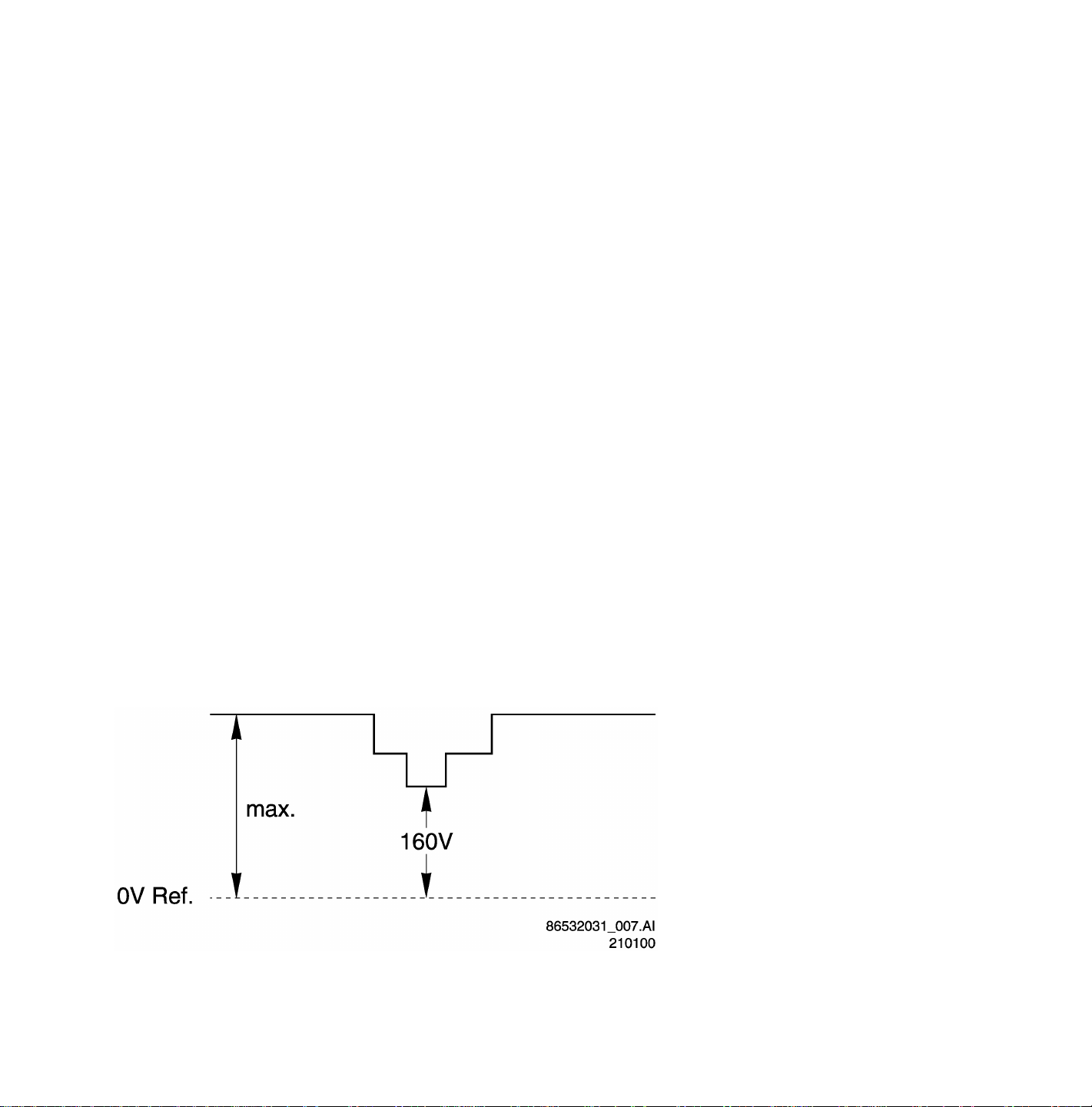
Black Level Pulse
Adjust the highest of the three guns with the VG2 potentiometer of the LOT to 160Vdc for 27FSQ-sets, while the minimum black
level voltage 165Vdc is for 32” / 36” FSQ-sets and 29” / 34” RF picture tubes.
Focus Adjustment
Using a pattern generator displaying a crosshatch pattern, adjust the focus potentiometer of LOT L5431 in such a way that the
haze on the vertical lines at 2/3 from the left and right edges of the screen (just) disappears.
PIP AGC Adjustment
The Automatic Gain Correction adjustment prevents overdriving of the PIP-tuner if the input signal is too strong. Overdriving is
visible as a loss of color and synchronization in the PIP picture. Amplification has to be adjusted to minimum level, but the PIPpicture should be as free of noise as possible.
Adjustment
• Connect the pattern generator to the tuner.
• Select color bar without sound and apply a strong input signal of 4mV (72dBµV) and set frequency to 61.25MHz. (Channel
3).
• Connect an oscilloscope to the output of the tuner (pin 11).
• Adjust potentiometer R3942 so that the oscilloscope indicates 0.5Vpp.
• If an input signal is not available, adjust R3942 to 1/3 maximum (maximum is completely counterclockwise).
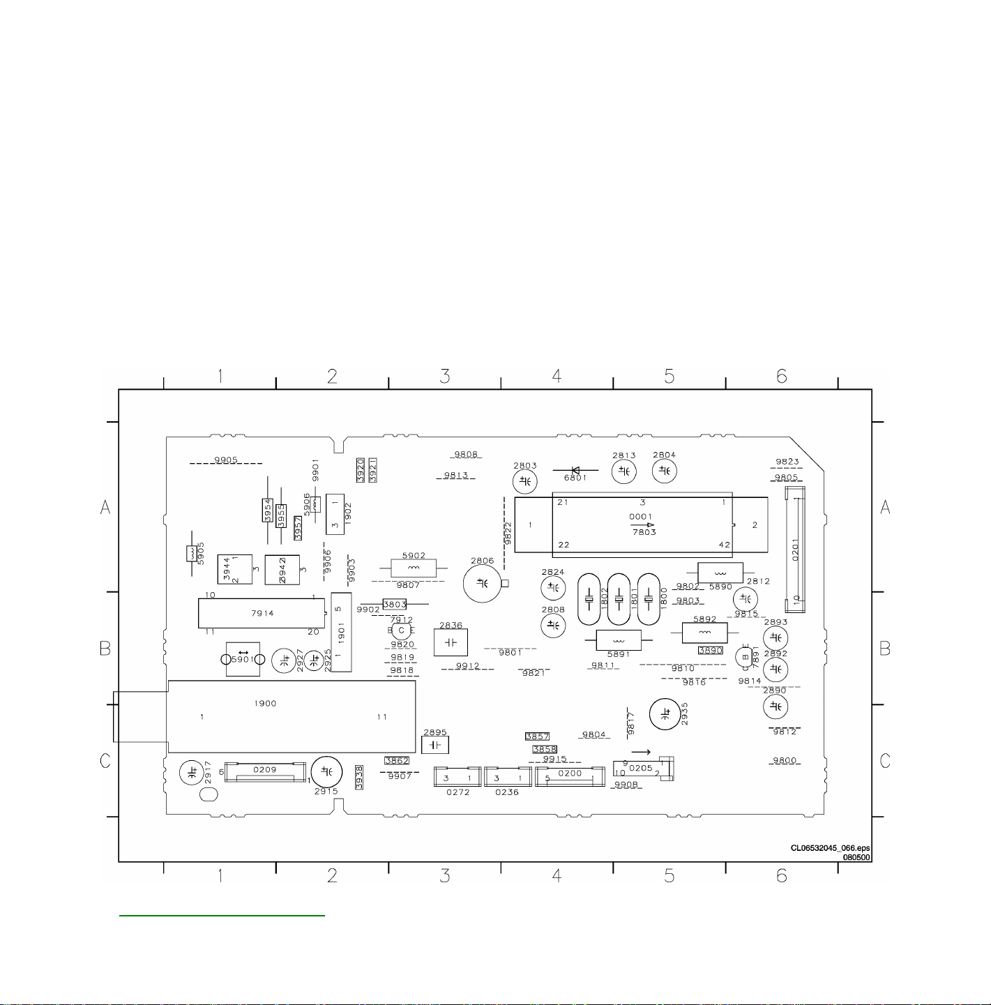
PIP Panel PCB (Top View)

PIP AFC Adjustment
• Connect a video generator with a color bar and a frequency of 61.25 MHz to the tuner.
• Connect a multimeter to the AFC output on pin 15 of IC 7914 – TDA9801
• Use potentiometer R3944 to adjust the AFC output to 2.6 Volts.
Software alignments (Service Alignment Mode)
With the software alignments of the Service Alignment Mode, the geometry, white tone and tuner (IF) can be aligned.
Service Alignments Mode screens and structure
Tuner (Large Signal Panel and Double Window)
AGC Adjustment
Set pattern generator with gray scale video signal and connect to antenna input with RF signal amplitude - 10mV and set
frequency to 63.25 MHz.
• Enter SAM (see Software alignments (Service Alignment Mode)). Press Cursor Down button to highlight the TUNER menu
item. Press Cursor Right button to enter the TUNER submenu. Press Cursor Down button to highlight the AFC submenu
item. Use the Cursor Left/Right buttons to set the value of AFC to 100kHz.
• Press the Cursor Down button to highlight AGC submenu item.
• Connect a DC multi-meter to pin 1 of the tuner IC 1225 ( Large Signal Panel ) or IC 1900 ( Double Window PIP Panel ).
• Press the Cursor Right/Left buttons to adjust the AGC register value until the voltage at pin 1 of the tuner is within 2.5 V
AGC takeover voltage of 3.8 V.
• Press the power button on the local keyboard or the remote control to turn the power off and save the settings.
Tuner options - IF PLL OFFSET and AFC WINDOW
NO ADJUSTMENT IS NECESSARY FOR THESE MENU ITEMS
The default values for these options are:
• IF PLL OFFSET : 32
• AFC WINDOW : 100kHz
White Tone Adjustment
Enter SAM (see Software alignments (Service Alignment Mode)). Press the Cursor Down button to highlight the WHITE TONE
menu item. Press the Cursor Right button to enter the WHITE TONE submenu. In the white tone submenu the values for the
color temperature values can be adjusted.
The color can be selected with the Cursor Up/Down buttons. The value can be changed with the Cursor Left/Right buttons.
First the values for the NORMAL color temperature should be selected. Then the offset values for the DELTA COOL and
DELTA WARM mode can be selected. Note that the alignment values are non-linear
0 represents the middle value (no offset difference).
Submenu: WHITE TONE
NORMAL
NORMAL RED 0..63
NORMAL GREEN 0..63
NORMAL BLUE 0..63
DELTA
COOL
DELTA COOL
DELTA COOL
DELTA COOL
DELTA
WARM
DELTA WARM
DELTA WARM
DELTA WARM
RED
BLUE
GREEN
RED
BLUE
GREEN
Values Remarks
-63..0..+63 The displayed values will satisfy the following
equation: 0 <= (NORMAL RED + DELTA
COOL RED) <= 63
EXAMPLE: If NORMAL RED = 40, then
DELTA COOL RED will range from –40 to 23.
-63..0..+63 Similar rule to DELTA COOL RED applies.
-63..0..+63 Similar rule to DELTA COOL RED applies.
-63..0..+63 Similar rule to DELTA COOL RED applies.
-63..0..+63 Similar rule to DELTA COOL RED applies.
-63..0..+63 Similar rule to DELTA COOL RED applies.

Geometry Adjustment
The geometry alignments menu contains 13 items for correct picture geometry alignment. In widescreen models, the
GEOMETRY SW is available for separate alignments of the superwide (panorama) mode. The geometry alignments are:
Initial set-up:
• Press the PICTURE button on the remote control repeatedly to change the Smart Picture setting to "SPORTS."
• Enter SAM (see Software alignments (Service Alignment Mode)).
• Press the Menu Down button to select the GEOMETRY menu item.
• Press the Cursor Right button to enter the GEOMETRY submenu.
• Press the Cursor Down button to highlight the VER-SCOR submenu item.
• Use the Cursor Right buttons to adjust VER-SCOR to 13 for 27”, 28”, 32” and 34” picture tubes.
• Use the Cursor Right buttons to adjust VER-SCOR to 23 for 29” RF- sets
• Vertical zoom should be set at a default value of 35.
• Vertical scroll should be set at a default value of 32.
VER-SCOR aligns the vertical linearity, so that the vertical intervals of the grid-patterns are the same over the entire height of
the screen.
Extra Alignment for 4:3 sets
• Set Service blanking on SERV-BLK ON
• Adjust Vertical slope VER-SLOPE xx
• Set Service blanking OFF SERV-BLK OFF
General Alignment (4:3 set)
• Adjust Vertical amplitude VER-AMPL xx
• Adjust Vertical shift VER-SHIFT xx
• Adjust Horizontal shift HOR-SHIFT xx
• Adjust Vertical height VER-ZOOM xx
• Adjust Vertical position VER-SCROLL xx
• Adjust Vertical linearity VER-SCOR xx
• Not used H60-SHIFT xx
• Not used V60-AMPL xx
• Adjust Horizontal width EW-WIDTH xx
• Adjust Parabola EW-PARA xx
• Adjust Up corner EW-UCORN xx
• Adjust low corner EW-LCORN xx
• Adjust Trapezium EW-TRAP xx
• Adjust Horizontal parallelogram HOR-PARALLEL xx
• Adjust Horizontal bow HOR-BOW xx

Geometry Submenu Item Descriptions
SERV-BLK: - To turn on/off the blanking of the lower half of the screen (To be used in combination with the vertical slope
alignment)
VER-SLOPE - To adjust the picture so the proportions are the same at the top and bottom of the screen. (This alignment
must be performed first, before all other vertical alignments)
VER-AMPL - To align the picture height (other vertical alignments are NOT compensated)
VERSHIFT - To align the vertical center of the picture to the vertical center of the CRT
HORSHIFT - To align the horizontal center of the picture to the horizontal center of the CRT
VER-ZOOM - To adjust picture height
VER-SCROLL - To vertically align the raster
VER-SCOR - To adjust the vertical linearity of the picture
H60-SHIFT - Not used
V60-AMPL - Not used
EW-WIDTH - To align the picture width (*)
EW PARA - To align straight vertical lines at the sides of the screen (*)
EW-UCORN - To align straight vertical lines in the upper corners of the screen (*)
EW-LCORN - To align straight vertical lines in the lower corners of the screen (*)
EW TRAP - To align straight vertical lines at the middle of the screen (*)
HOR-PARALLEL - To align straight vertical lines at the top and at the bottom of the screen; vertical rotation around the center
(*)
HOR-BOW - To align straight horizontal lines at the top and the bottom of the screen; horizontal rotation around the center
Alignments indicated with (*) are not applicable for sets without East/West circuitry
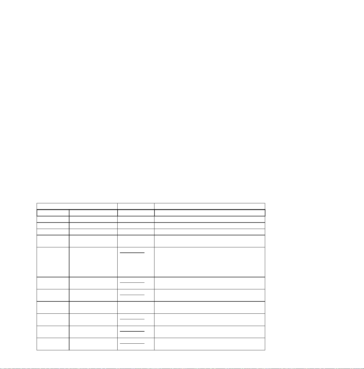
Options/Features
Options are used to control the presence / absence of certain features and hardware. There are two ways to change the option
settings, see Figure 2: Service Alignments Mode screens and structure.
Changing a single option
An option may be selected with the MENU UP/DOWN keys and then changed with the MENU LEFT/RIGHT keys.
Changing multiple options by changing option byte values
Option bytes make it possible to set all options quickly. An option byte represents a number of different options. All options of
the H8 are controlled via 8 option bytes. Select the option byte (OB1, OB2, OB3, OB4, OB5, OB6, OB7 or OB8) and enter the
new value.
List of options
Unless otherwise stated ON means the option is turned on or present, OFF means the option is turned off or not present.

Option Codes for Single Tuner PIP, and 2 Tuner PIP
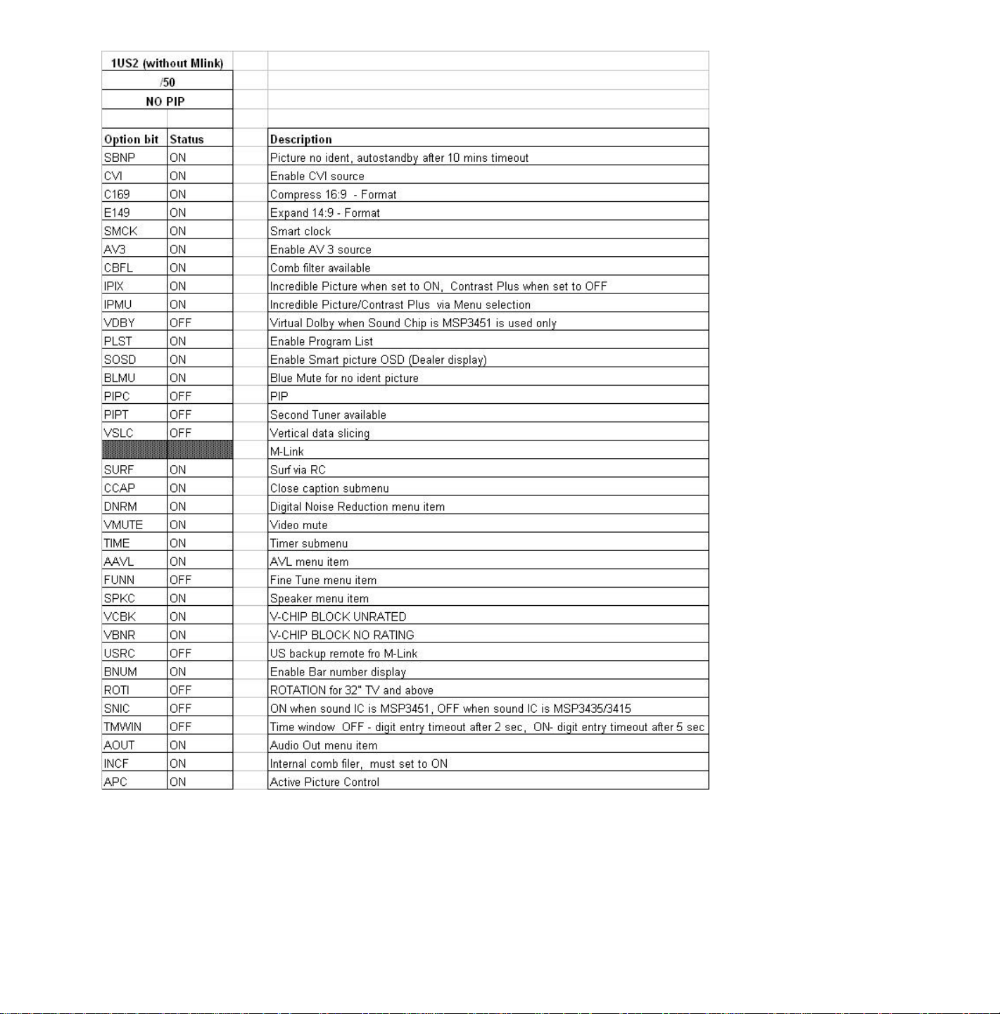
Option Codes for Models Without PIP
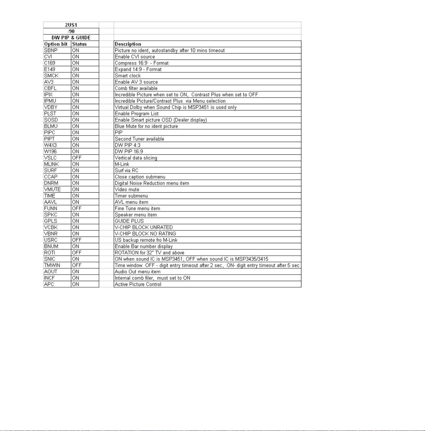
Option Codes for Double Window
Option bits/bytes
Option bytes for NAFTA models (4:3 Standard Screen) with software named: A10_1US1.
OB1 bits 8, 7, ..., 1: SBNP, CVI, C169, E149, SMCK, AV3, CBFL, and IPIX
OB2 bits 8, 7, ..., 1: IPMU, VDBY, PLST, SOSD, BLMU, PIPC, PIPT, VSLC
OB3 bits 8, 7, ..., 1: MLNK, SURF, CCAP, DNRM, VMUT, TIME, AAVL, FUNN
OB4 bits 8, 7, ..., 1: SPKC, VCBK, VBNR, USRC, BNUM, ROTI, SNIC, TMWIN
OB5 bits 8, 7, ..., 1: AOUT, INCF, APC, NVM, (res), (res), (res), (res)
OB6 bits 8, 7, ..., 1: (RESERVED)
OB7 bits 8, 7, ..., 1: (RESERVED)
OB8 bits 8, 7, ..., 1: (RESERVED)
Option bytes for NAFTA models (Flat Screen 16:9 Screen) with software named : A10_1US1.
OB1 bits 8, 7, ..., 1: SBNP, CVI, C169, E149, SMCK, AV3, CBFL, IPIX
OB2 bits 8, 7, ..., 1: IPMU, VDBY, PLST, SOSD, BLMU, PIPC, PIPT, W4X3
OB3 bits 8, 7, ..., 1: W169, VSLC, MLNK, SURF, CCAP, DNRM, VMUT, TIME
OB4 bits 8, 7, ..., 1: AAVL, FUNN, SPKC, GPLS, VCBK, VBNR, USRC, BNUM
OB5 bits 8, 7, ..., 1: SNIC, TMWIN, STOR, AOUT, INCF, APC, (res), (res)
OB6 bits 8, 7, ..., 1: (RESERVED)
OB7 bits 8, 7, ..., 1: (RESERVED)
OB8 bits 8, 7, ..., 1: (RESERVED)
An option byte value is calculated in the following way:
value “option bit 1” x 1 =
value “option bit 2” x 2 =
value “option bit 3” x 4 =
value “option bit 4” x 8 =
value “option bit 5” x 16 =
value “option bit 6” x 32 =
value “option bit 7” x 64 =
value “option bit 8” x 128 =
Total value is “option byte” =
Option Code Bytes
MODEL OPTION BYTES
1 2 3 4 5 6 7 8
27PT31B121
27PT41B121
27PT71B121
27PT81S125
27PT91S125
32PT41B121/9
32PT71B121/9
32PT81S121/7
36PT41B129
36PT71B129
27RF70S125
32RF50S121/7
27DV60S125
32DV60S127
29PD802
255 184 126 232 208 0 0 0
255 188 254 232 208 0 0 0
255 190 254 232 208 0 0 0
255 190 254 232 208 0 0 0
127 255 127 245 122 0 0 0
255 188 254 232 208 0 0 0
255 190 254 232 208 0 0 0
255 190 254 236 208 0 0 0
255 188 254 232 208 0 0 0
255 190 254 232 208 0 0 0
255 188 254 232 208 0 0 0
255 184 126 236 208 0 0 0
251 223 186 056 0 0 0 0
251 223 187 056 0 0 0 0
251 223 250 056 0 0 0 0
(EXPORT)
Service Modes & Error Messages
The following topics are covered:
• Test points
• Service Modes and Dealer Service Tool (DST)
• Error code buffer and error codes
• The “blinking LED” procedure
• Trouble shooting tips
• Customer Service Mode
Test points
The H8 chassis is equipped with test points shown on the CBA and the schematic diagrams.
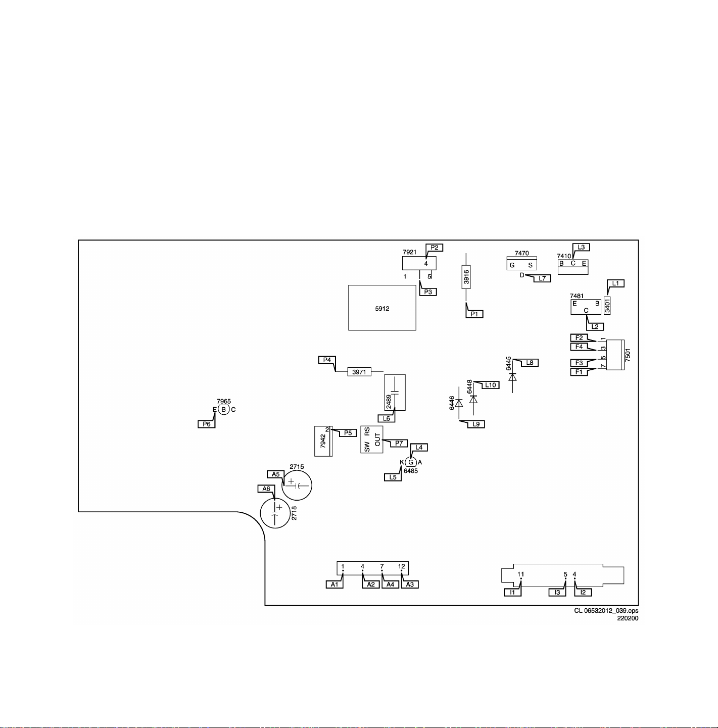
Large Signal Panel PCB Test Point Guide
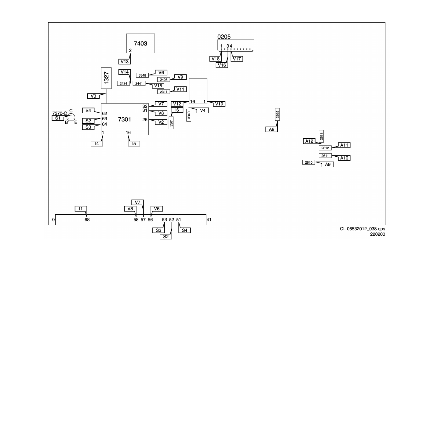
Small Signal Panel PCB Test Point Guide
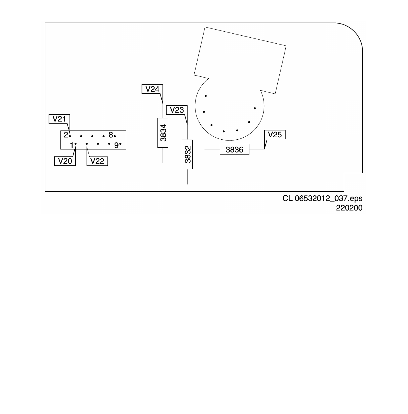
CRT Panel PCB Test Point Guide
Each test point has a reference number indicating the functional block in which it is located.
• A1-A2-A3, etc.: Test points for the audio processing circuitry [A6, C6]
• C1-C2-C3, etc.: Test points for the control circuitry [C8]
• F1-F2-F3, etc.: Test points for the frame drive and frame output circuitry [A3]
• I1-I2-I3, etc.: Test points for the Intermediate Frequency Circuitry [A4, C1]
• K1-K2-K3, etc: Test points for the Guide+ panel
• L1-L2-L3, etc.: Test points for the line drive and line output circuitry [A2] and PIP-panel
• P1-P2-P3, etc.: Test points for the power supply [A1]
• S1, S2, S3, etc.: Test points for the synchronization circuitry [C1]
• V1-V2-V3, etc.: Test points for the video processing circuitry [B, C2, C3]
Measurements should be performed under the following conditions:
Video: NTSC color bar signal
Audio: 3kHz left, 1kHz right

Service Default Mode (SDM)
Introduction
The Service Default Mode (SDM) is a technical aid for the service technician. The Service Default Mode (SDM) establishes
fixed, repeatable settings of customer controls, which allow consistent measurements to be made. The SDM also initiates the
blinking LED procedure and, if necessary, overrides the 5V protection.
The SDM places the set in the following pre-defined conditions:
• Tuning frequency set to 61.25 MHz (channel 3).
• Volume level set to 25% (of the maximum volume level).
• Other picture and sound settings set to 50% (mid-range)
The following functions are turned off in SDM (and after leaving SDM):
• Timer
• Sleep timer
The following functions are disabled during SDM (and enabled after leaving SDM):
• Parental lock
• Blue mute
• Hospitality Mode
• No-ident Timer (normally the set is automatically switched off when no video signal (IDENT) was received for 15 minutes).
All other controls operate normally.
Entering Service Default Mode
To enter the Service Default Mode, press the following key sequence on the remote control transmitter:
0-6-2-5-9-6-Menu
Do not allow the display to time out between entries while keying the sequence.
It is also possible to enter the Service Default Mode by temporarily short-circuiting jumpers 9261 and 9262 while turning the set
on By shorting jumpers 9261 and 9262 while turning the set on.
Note: Entry into SDM by temporarily shorting jumper 9261 and 9262 while turning the set on, the 5V protection will be
disabled.
CAUTION! Overriding the 5V protection should only be used for a short period of time. In case of S/W protections
(error 1-4) the set will shutdown after 15 sec.
Upon entry into the Service Default Mode, the letters “SDM” will be displayed at the upper right corner of the screen.
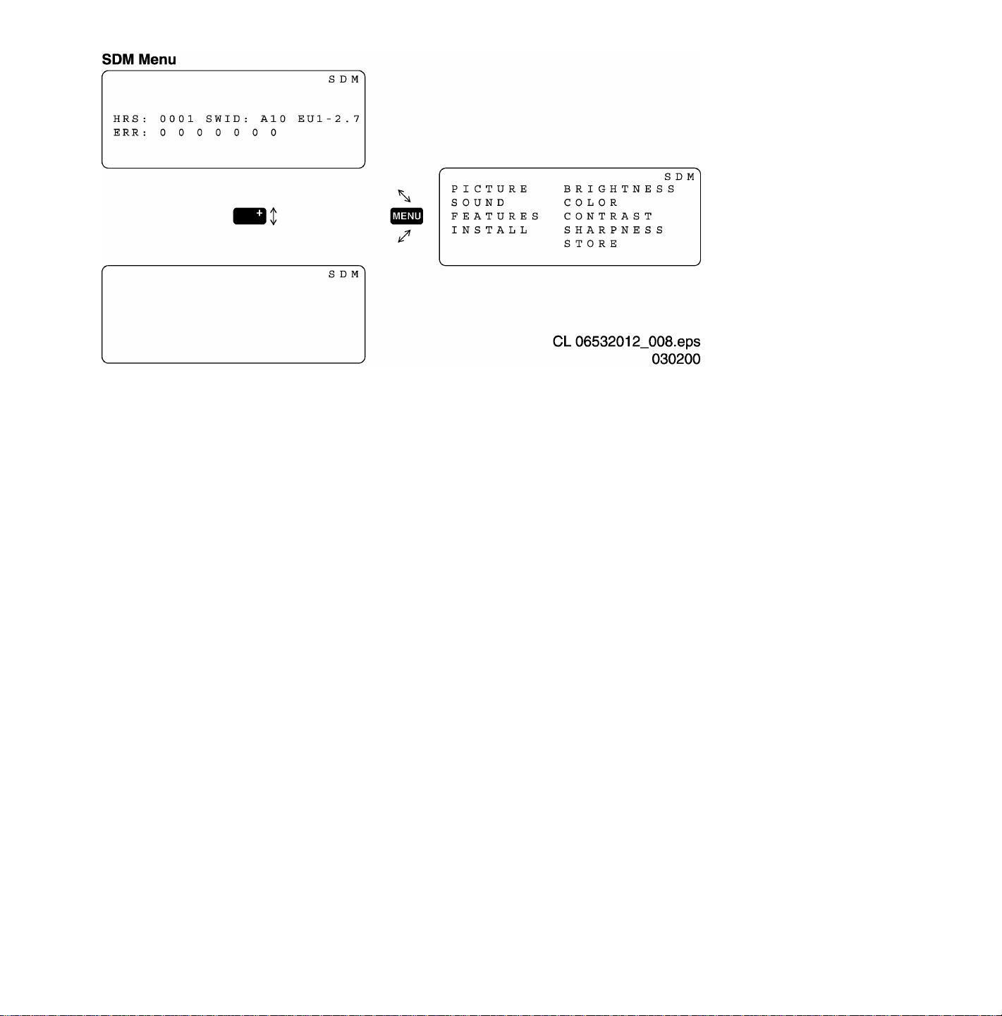
Service Default Mode (SDM) Screen
Special SDM functions
Access to normal user menu
Pressing the “MENU” button on the remote control switches between the SDM and the normal user menus (with the SDM
mode still active in the background)
Auto Program
Press the Cursor Down button and highlight the "Install" menu item. Press the Cursor Right button to highlight the "Language
" menu item. Press the Cursor Down button until the "Auto Program" menu item is highlighted. Press the Cursor Right button
to activate Auto Program.
Auto programming is indicated by a blinking LED; the LED will discontinue blinking when a transmitter is located.
Error buffer
To show/hide the error buffer press the “Status/Exit” button on the remote control. The error buffer information can be hidden
to prevent interference with oscilloscope measurements.
Access to SAM
To access the Service Alignment Mode while in the SDM press the “VOLUME +” and “VOLUME –“ buttons on the local
keyboard simultaneously.
Exiting Service Default Mode
To exit the Service Default Mode, press the Power button.
Note: To save the error codes, unplug the AC power cord without turning off the set. When the power is turned back
on, the Service Default Mode will still be active.

Service Alignment Mode (SAM)
Introduction
The Service Alignment Mode (SAM) is used to align the set and/or adjust the option settings and to display/clear the error code
buffer values.
Entering Service Alignment Mode
To enter the Service Alignment Mode (SAM), press the following key sequence on the remote control transmitter:
0-6-2-5-9-6-STATUS
Do not allow the display to time out between entries while keying the sequence
It is also possible to enter the Service Alignment Mode by pressing the “VOLUME +” and “VOLUME -” key on the local keyboard
simultaneously when the set is in SDM
Exiting the Service Alignment Mode (SAM)
To Save Changes and Exit:
Press the Menu button on the Remote Control until you have backed-up to the upper level SAM Menu.
Upon returning to the upper level SAM Menu, pressing the power button on the Remote Control or the set's own front control
will cause current register settings to be saved. The set will pause for a few seconds (while saving this data), and then both exit
the SAM Mode and shut down.
Note: Pressing the power button, while in a sub-menu, will exit the SAM Mode and cause the set to shut down, but changes
will not be saved.
Note: To save the error codes, unplug the AC power cord without turning off the set. When the power is turned back
on, the Service Alignment Mode will still be active.
In the SAM the following information is displayed on the screen:

SAM Screen and Menu Structure
Explanation notes/references:
1 Operation Hours (Run Timer):
This display indicates the accumulated total of operational hours. (Shown in hexadecimal
format)
2 Software identification of the main micro controller (A10US1-2.7)
A10 is the engineering chassis name for the H8 chassis
• US1 is 2 letter and 1 digit combination to indicate the software type and the supported
languages:
• US = USA
• 1 = Main Software language version number
• 2.7 = sub-version number
3 Error buffer (7 errors possible) Displays the 7 most recent errors. The most recent
error is displayed at the upper left.
4 Option bytes (8 codes possible), summary of options are explained below.
5 Sub menus are listed in a scroll-menu.
SAM Menu Control
Menu items may be selected using the cursor UP/DOWN key.
• The selected item will be highlighted.
• When not all menu items will fit on the screen, pressing the cursor UP/DOWN key on the remote transmitter will display the
next/previous menu items.
With the cursor LEFT/RIGHT keys, it is possible to:
• (de)activate the selected menu item (e.g. GEOMETRY)
• change the value of the selected menu item ( e.g. VER-SLOPE )
• activate the selected submenu (e.g. SERV-BLK)
Access to normal user menu
Pressing the “MENU” button on the remote control switches between the SDM and the normal user menus (with the SAM
mode still active in the background). Pressing the “MENU” key in a submenu will return the screen to the previous menu.
The Menus and Submenus
CLEAR ERRORS
Erasing the contents of the error buffer. Select the CLEAR ERRORS menu item and press the MENU RIGHT key. The
content of the error buffer is cleared.
The functionality of the OPTIONS and ALIGNMENTS (TUNER, WHITE TONE, GEOMETRY and SMART SETTING) sub
menus is described in the service adjustments.
Error code buffer and error codes
Explanation of the Error code buffer
The error code buffer contains all errors detected since the last time the buffer was erased. The buffer is written from left to
right. When an error occurs that is not yet in the error code buffer, the error code will appear at the left side and all other
errors shift one position to the right.
The error code buffer will be cleared in the following cases:
• by activating CLEAR ERRORS in SAM menu
• exiting SDM or SAM with the “Standby" command on the remote control

• upon automatic reset when content has not changed for 50 consecutive hours
By leaving SDM or SAM via the power switch, the error buffer will not be reset.
Examples:
ERROR: 0 0 0 0 0 0 0 : No errors detected
ERROR: 6 0 0 0 0 0 0 : Error code 6 is the last and only detected error
ERROR: 9 6 0 0 0 0 0 : Error code 6 was first detected and error code 9 is the last detected (newest) error
The contents of the error buffer can also be displayed by use of the “blinking LED” procedure, if no picture is available. See
explanation of “The blinking LED procedure “below.
Error code definition
In case of non-intermittent faults, clear the error buffer before starting the repair, to make sure “old” error codes are not present.
If possible check the entire content of the error buffers. In some situations an error code is only the result of another error code
(and not the actual cause).
Note: a fault in the protection detection circuitry can also lead to a protection.
Error 0 = No error
Error 1 = X-ray protection, E/W protection and/or Beam
X-ray protection, E/W protection and/or Beam; set is switched to protection; error code 1 is placed in the error buffer; the LED
will blink 1 time (repeatedly). If this happens, isolate each circuit to determine the cause. These circuits are:
• x-ray protection – PROTN
If this protection is active, the most likely cause is the LOT. Detection via pin 3 of the signal processor – item 7301.
• EW protection – PROT-UP
If this protection is active, the causes could be one of the following:
• bad contacts of:
- horizontal deflection coil
- linearity coil 5417
- S-correction capacitor 2418/2419
- flyback capacitor 2414/2416
- line output stage
• short circuit of:
- flyback diode 6414
- EW transformer (bridge coil) 5478/5479 or 5474/5475/5476 (item number depends upon the model version)
- EW driver 7470
• High beam current protection - Beam
As the name implies, what causes this protection is a high beam current (bright screen with flyback lines) which is too high.
Check for the presence of the +200V supply to the CRT panel. If the voltage is present, the most likely cause is the CRT
panel or the picture tube. Disconnect the CRT panel to determine the cause. If the +200V voltage is not present, check
R3840 at CRT-panel and R3445 & D6445 on the main chassis.
Error 2 = Vertical protection - VFB
If this protection is active, the cause could be one of the following (most likely in the vertical output stage):
- 7501 is faulty
- poor contact or open circuit of deflection coil
- +13V-VERT and/or -13V not present
Error 3 = Reserved

Error 4 = +5V protection
5V protection active; set is switched to protection; error code 4 is placed in the error buffer; the LED will blink 4 times
(repeatedly). A 5V failure can cause a drop in the 5V-supply output, resulting in an undefined behavior of the set. Therefore, all
I2C devices connected to the 5V supply are constantly monitored. When none of these devices responds to the micro controller
for a prolonged time, the micro controller assumes that there is a failure in the 5V supply.
By starting up the set with the service jumpers shorted, the 5V protection is disabled and it is easier to determine the cause.
+5V protection will be activated when these I2C devices fail (no I2C communication):
• Main Tuner – 1125 on main panel
• ITT sound processor – MSP34xx (7064) on the SSB
The following tips are useful to isolate the problem area after overriding the +5V protection. Determine whether:
• The +5V source is working properly; isolate coil 5430 and jumper 9044 and measure the +5V
• ITT sound processor circuit is loading the +5V; isolate coil 5430
• The tuner is loading the +5V source; isolate jumper 9044
• Main tuner circuit is loading the +5V source; isolate coil 5261
Caution! Overriding the 5V protection when there is a 5V failure can increase the temperature in the set and may cause
permanent damage to components. Do not override the 5V protection for a prolonged period of time.
Error 5 = Reserved
Error 6 = General I2C error. This error code will be displayed in the following cases:
• SCL or SDA is shorted to ground
• SCL is shorted to SDA
• SDA or SCL connection at the micro controller is open circuit.
Error 7 = BC-loop not stabilized (BCF = 1) Black current loop instability protection. The possible cause could be a defect in
one or more of the RGB amplifiers, RGB guns or RGB driving signals.
Error 8 = BOCMA (signal processor) IC – TDA888xx I2C communication failure. BOCMA (item 7301 on SSB) is corrupted or
the I2C line to the BOCMA is low or no supply voltage present at pin 14 and/or pin 60 (3V3)
Error 9 = BOCMA (signal processor) IC – TDA888xx 8V failure (SUP bit). No supply voltage at pin 53. Check NFR 3331 and
coil 5333.
Error 10 = Non Volatile Memory I2C error. NV memory (EEPROM – item 7066) does not respond to the micro controller.
Error 11 = Micro controller / NV Memory identification error. During the last start-up the NVM and the micro controller did not
recognize each other (e.g. one of them was replaced or the NVM memory has been changed/adapted or lost),
therefore the NVM was loaded with default values.
Error 12 = Microprocessor (Painter – item 7064) internal RAM test failure.
Error 13 = Main Tuner I2C failure UV13xx. Tuner (item 1225) is corrupted or the I2C line to the Tuner is low or not supplying
voltage at pin 9, pin 6 or pin 7 of the tuner.
Error 14 = Sound processor I2C error (MSP34xx -). Sound controller MSP3400 or MSP3410 does not respond to the micro
controller.
Error 15 = SRAM (Static Random Access Memory) IC uPD431000A-B test failure (item – 7070).
Error 16 = PIP/DW Tuner I2C error. The Tuner (TEDE9 – item 1900) on the PIP-panel does not respond to the micro
controller.
Error 17 = PIP IC – M65669SP I2C failure (item 7803) or Double Window IC SAB9081 I2C failure.
Error18 = I/O expander IC – 62320P I2C failure (item 7910 on PIP panel).
Error 19 = Guide+ I2C failure (LC27016B – item 7005).
Error 20 = V-chip for PIP, IC ZILOG 86130 I2C failure.
Error 21 = NV clock IC MK41T56 I2C failure at mono board – Item 7011 at A7. (Latam only)
Error 22 = Reserved.
Error 23 = Second BOCMA IC – TDA888xx (item 7301on Double Window PIP panel) I2C communication failure.
Error codes 1,2, and 4 are protection codes, and in this case the supplies of some circuits will be switched off. Also in
protection, the LED will blink the number of times equivalent to the most recent error code.
Error code table
Error code Error description Possible defective components
0 No error detected —
1 X-ray protection/ EW and/or High
beam protection active
2 Vertical protection Vertical circuit is defective
3 Reserved
4 5V protection active +5V supply line is low or short circuit
5 Reserved
6 General I2C bus error
7 BC-loop not stabilized RGB amplifiers, RGB guns or RGB
8
BOCMA (signal processor) I2C error
9 BOCMA (signal processor) 8V
supply failure
10
NVM I2C error
11 NVM identification failure IC 7066
12 µProcessor internal RAM test failure IC 7064
13
Main Tuner I2C error
14 Sound processor I2C error IC 7 (2CS/Nicam)
15 SRAM I2C error IC 7070
16
17
PIP tuner I2C error
PIP IC I2C error or DW IC I2C error
18 I/O expander IC 62320P I2C error IC 62230P – item 7910
19
20
21
Guide+ I2C error
V-chip for PIP – I2C error
NV clock – I2C error
22 Reserved
23 Second BOCMA (signal processor)
IC (on Double Window PIP panel) –
I2C error
LOT, Line deflection circuit, EW-circuit
or CRT amplifier circuit, picture tube or
+200V missing
I2C bus s/c or o/c on µP
driving signals of BOCMA
IC 7301on SSB
IC 7301 and R3331on SSB
IC 7066
IC 1225 – UV13xx
IC 1900 – TEDE9
IC LC27016B – item 7005
IC ZILOG 86130 -
IC MK41T56 – item 7011
IC TDA888xx – item 7301on Double
Window PIP Panel

The Blinking LED Procedure
The contents of the error buffer can also be made visible through the “blinking LED” procedure. This is especially useful when
there is no picture.
• When the SDM is entered, the LED will blink the number of times, equal to the value of the error code.
Upon entry into the SDM, the LED will blink the contents of the error-buffer.
Error-codes greater than/equal to 10 are shown in the following manner:
A long blink of 750 mSeconds Indicating the decimal digit, followed by a pause of 1500 mSeconds. The LED will then blink
the number equal to the error code. When all error-codes are displayed, the sequence is finished with an LED display of 3
seconds. At this point the sequence will begin again.
Example:
Error code position 1 2 3 4 5
Error buffer: 12 9 6 0 0
• After entering SDM:
• The sequence will begin with 1 long blink of 750 mSeconds, then pause 1500 mSeconds, then blink twice (indicating error
code 12), then the LED will pause for 3 seconds, then blink 9 times (indicating error code 9), then the LED will pause for 3
seconds, then blink 6 times (indicating error code 6), then pause 3 seconds and blink for 3 seconds again, ending the
blinking sequence.
NOTE: If errors 1, 2 or 4 occur the LED ALWAYS blinks indicating the last error which occurred, even if the set is NOT in
service mode.
Customer Service Mode (CSM)
All H8 sets are equipped with the “Customer Service Mode” (CSM). CSM is a special service mode that can be activated and
deactivated by the customer, by request of the service technician/dealer in order to identify the status of the set. This CSM is a
'read only' mode, therefore modifications in this mode are not possible.
Entering the Customer Service Mode.
The Customer Service Mode can be switched on:
• By pressing the MUTE button on the remote control and any key on the local keyboard (Channel Up, Channel Down, VOL
+, VOL -) on the TV simultaneously for at least 4 seconds.
When the CSM is activated:
• picture and sound settings are set to nominal levels
• Modes that interfere with the behavior of the set are switched off (sleep timer, auto standby, etc.)
Exit the Customer Service Mode.
The Customer Service Mode will be switched off after:
• Pressing any key on the remote control (except “Channel Up” or “Channel Down”)
• Switching off the TV set by pressing the Power button on the remote control or the local keyboard.
Exiting CSM resets the TV set back to its initial values.
The Customer Service Mode information screen
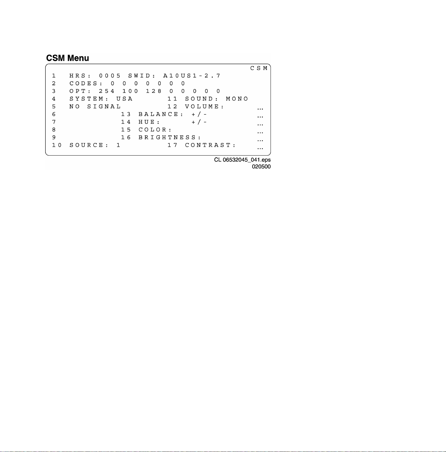
Upon entry into the Customer Service Mode the following screen will appear.
CSM Menu Screen
The Customer Service Menu shows the following information:
- Line 1 : “HRS : nnnnn” and SWID : “A10BBC-X.Y”
HRS:
Indicates the accumulated total of operational hours. (Shown in hexadecimal format.) (Standby hours are not counted as
operating hours).
SWID:
Software identification of the main micro controller (example: A10US1-2.7)
A10 is the engineering chassis name for the H8 chassis
• US1 is 2 letter and 1 digit combination to indicate the software type and the supported languages:
• US = USA
• 1 = Main Software language version number
• 2.7 = sub-version number
- Line 2 : “CODES : xx xx xx xx xx xx xx ”
Error code buffer (see explanation of error codes above) Displays the last 7 errors of the error code buffer.
- Line 3 : “OPT xxx xxx xxx xxx xxx xxx xxx xxx”
Option bytes
Option bits control the software and hardware functionality of the A10.0. An option byte or option number represents 8 of those
bits. Each option number is displayed as a number between 0 and 255. The set may not work correctly when an incorrect option
code is set. See Service Adjustments for more information on correct option settings
- Line 4: “SYSTEM : USA”
Indicates this set is equipped to receive an NTSC broadcast signal.
- Line 5 : “NO SIGNAL”
Indicates that the set is not receiving an “ident” signal on the selected source.
• no or bad antenna signal; connect a proper antenna signal
• antenna not connected; connect the antenna
• no channel / preset is stored at this program number; go to the INSTALL menu and store a proper channel at this program
number
• the tuner is faulty (in this case the CODES line will contain number 13 or 16); check the tuner and replace/repair if
necessary
Note: On some models, (if the BM option is ON), BLUE MUTE is displayed when no signal is received.

- Line 6 : “TIMER ON ”
Indicates that the on/off timer is running.
The following Complaints may be caused by the activation of the sleep timer:
The set may turn on from standby or may switch to a different channel without using either the remote control or the local
keyboard.
To switch off the activation timer:
Select “TIMER” in the “FEATURE” menu.
Select “ACTIVATE’ in the “TIMER” menu.
Set to “OFF” with the left/right cursor keys.
- Line 7 : NOT AVAILABLE
- Line 8 : “NOT PREFERED”
Indicates that at least one channel is deleted as a preferred channel (by default, all channels are skipped.
Note that “SKIPPED” will always be displayed in CSM unless all the channels are not skipped.
To add a channel as a selected channel to the list of preferred channels:
Select “INSTALL” menu
Select “CHANNEL EDIT”
Select “ADD/DELETE”
Set to “ADD” with the left/right cursor keys
- Line 9 : “HOTEL MODE ON”
Indicates that the Hotel mode has been activated.
- Line 10 : “SOURCE :”
Indicates which SOURCE is installed for this preset.
EXT1, SVHS2, EXT2, Tuner.
- Line 11 : “SOUND”
Indicates which sound mode is installed for this preset.
Mono, NICAM, Stereo, L1, L2, SAP, Virtual or Digital
- Line 12 : “VOLUME”
Value indicates level at entry CSM.
- Line 13 : “BALANCE”
Value indicates level at entry CSM.
- Line 14 : “HUE”
Value indicates level at entry CSM.
- Line 15 : “COLOR”
Value indicates level at entry CSM.
- Line 16 : “BRIGHTNESS”
Value indicates level at entry CSM.
- Line 17 : “CONTRAST”
Value indicates level at entry CSM.
H8 Technical Training
INTRODUCTION
The H8 TV Chassis is designed for the 2000-2001 model years. It comes in three screen sizes, which are 27,
32, and 36 inch. All Chassis versions have a Side Jack Panel, a Component Input, and Surround Speaker
Jacks. The Rear Jack and Side Jack Panels are equipped with Composite, Component, and SVHS inputs.
The sets are equipped with either a Standard Dark Glass picture tube or a Very Flat Square Invar picture tube.
The H8 Chassis comes in Non-PIP (Picture in Picture), Single Tuner PIP, two Tuners PIP, or Double Window
versions. Each time the User selects the PIP window, the PIP window appears, changes size, then disappears.
In the Double Window version when the PIP On/Off button on the Remote is pressed, a PIP window appears.
When the button is pressed again, the window changes size. Press it again and the picture goes to a double
window (split screen). Pressing the button again, the picture returns to normal. The XXPT41 and larger
models are equipped with the M-Link feature. The M-Link feature allows VCRs, DVD, etc to be controlled
through the TV. Up to five devices can be controlled. Refer to the Model to Module listing in the Service
Manual to determine which modules are in a given model. Other features include an Audio Volume Leveler
(AVL) to compensate for changes in volume level. AutoLock, which allows certain channels, or programs with
certain ratings to be blocked. Each time the set is turned Off and back On, the Access Code must be reentered
to view the blocked channels. If the Customer forgets the Access Code, entry into the Menu to change the code
can by obtained by entering Access Code 0711. To gain entry, the code must be entered twice. A Format
selection in the menu allows the user to select between 4x3, Zoom, or 16x9 aspect ratio for the picture. This is
accomplished by changing the Height and Width settings in the set.
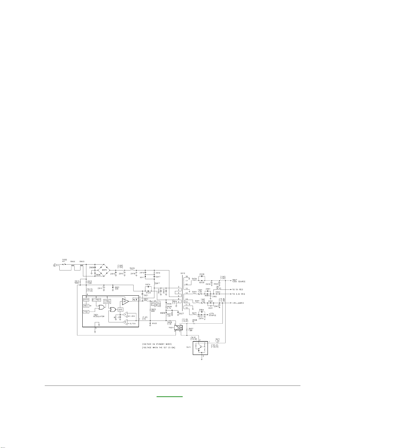
POWER SUPPLY
Switch Mode Supply Figure 1
The Power Supply is a Switching type supply. The Power Supply begins operating as soon as AC power is
applied to the set. AC power is applied to the Large Signal Board through Fuse 1900 and applied to the Bridge
Rectifier 6915. The rectified B+ voltage is applied to the regulator switching IC, 7921, through Pins 6 and 3 of
transformer 5912. Startup voltage for the supply is applied to Pin 4 through resistors 3914 and 3913. The Zener
Diode 6921 prevents the voltage on Pin 4 from exceeding 33 volts in case the Regulator IC is not working.
When the voltage on Pin 4 reaches 16 volts, the Oscillator inside the IC begins operating. Once the Supply is in
full operation, the operating voltage for the supply is supplied by Pin 8 of 5912 and is rectified by 6929. The
Oscillator drives the internal switching FET. When the FET is On, energy is stored in 5912. When the FET is
Off, energy is transferred to the secondary of 5912. The Frequency and On time of the internal switching FET is
determined by the Internal Comparator, the internal RC network, and the Magnetizing Inductance of the
Transformer. The Internal RC network also determines the Off time of the FET switch. The ramping voltage
determines the On Time across 3924, 3923, the feedback voltage from Pin 8 of the transformer, and the voltage
from the feedback opto-isolator. The Reference Voltage for the supply is the VBAT (135-volt source). This
source is sampled by 7971, which drives the feedback opto-isolator 7929 to set the switch time of comparator B.
This controls the On time of the internal switching FET to maintain the VBAT voltage at the correct level. There
are four output voltages from the transformer which are the VBAT voltage, 8 volts to the 5 and 3.3 volt
regulators, 8 volts unregulated, and 27 volts for the Audio Output circuit. To troubleshoot the Power Supply, first
check the VBAT (135-volt source). If this voltage is missing, check for a short on the VBAT line. The most likely
cause would be a shorted Horizontal Output Transistor. If the voltage is pulsing or is Low, check the feedback
circuit, 7971 and 7929. Also check Fuse 1941 on the 8 volt unregulated supply. This line supplies the operating
voltage for the feedback circuit. Next, check the B+ voltage for 7921 on Pin 3. If the drive signal is pulsing On
and Off on Pin 3, there may be a problem with the feedback circuit. If there is no drive signal on Pin 3, check for
the operating voltage on Pin 4. This voltage must ramp to 16 volts to start the supply. If it is missing or is not
ramping to 16 volts, check 3913, 3914, and 2919. Resistors 3923 or 3924 changing value could cause
regulation problems. If 7921 should fail, these resistors should be changed by using original parts only.
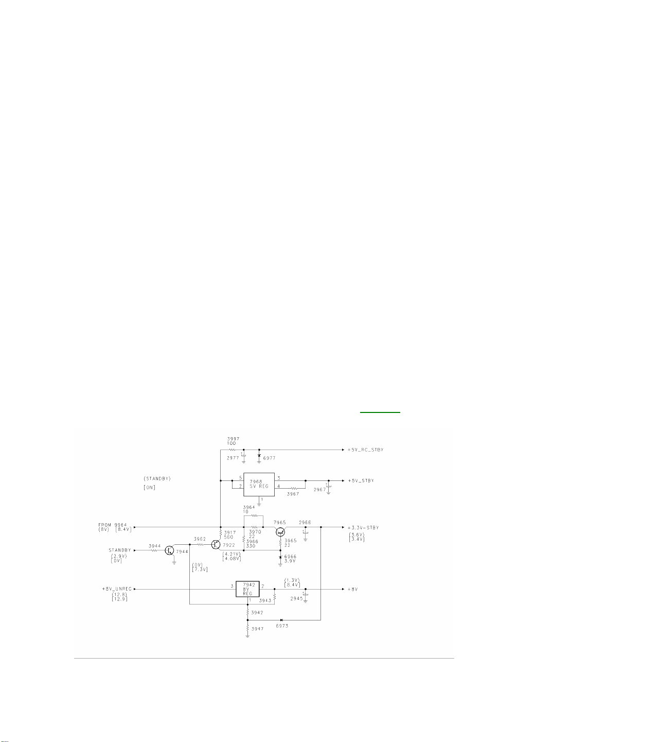
Standby Regulators and On/Off Figure 2
The voltage from jumper 9964 (approximately 8 volts) is used to produce the 3.3 volt standby, 5 volt standby, 5
volt remote control, and switched 8 volt supplies. The voltage is applied to transistor 7965 to produce the 3.3volt Standby supply. When the set is in the Standby mode, transistor 7944 is turned On, turning 7922 On,
providing a extra current drive for the 3.3 volt regulator. The 8 volt unregulated supply is applied to 7942, which
is a switched 8-volt regulator. The Standby line goes Low when the set is turned On, turning transistor 7944
Off, switching 7942 On. The switched 8-volt supplies the Horizontal Oscillator in the Signal Processor IC
located on the SSB.
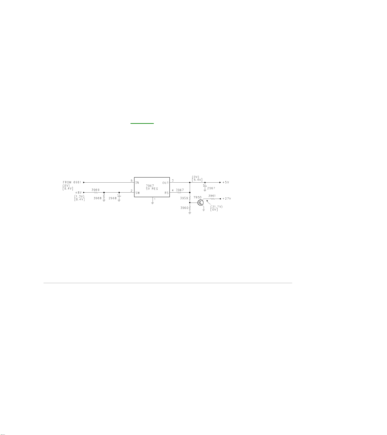
Five Volt Switch Figure 3
The Switched 8-volt supply also turns On the 5 volt regulator, 7967, to produce a switched 5 volt supply. The
Switched 5-volt supply turns transistor 7950 On. This provides a load on the 27-volt Audio Supply line to
discharge any remaining voltage on the line in the event that power is removed from the set while it is being
turned On. This is necessary to prevent a POP in the speaker while the set is powering down.
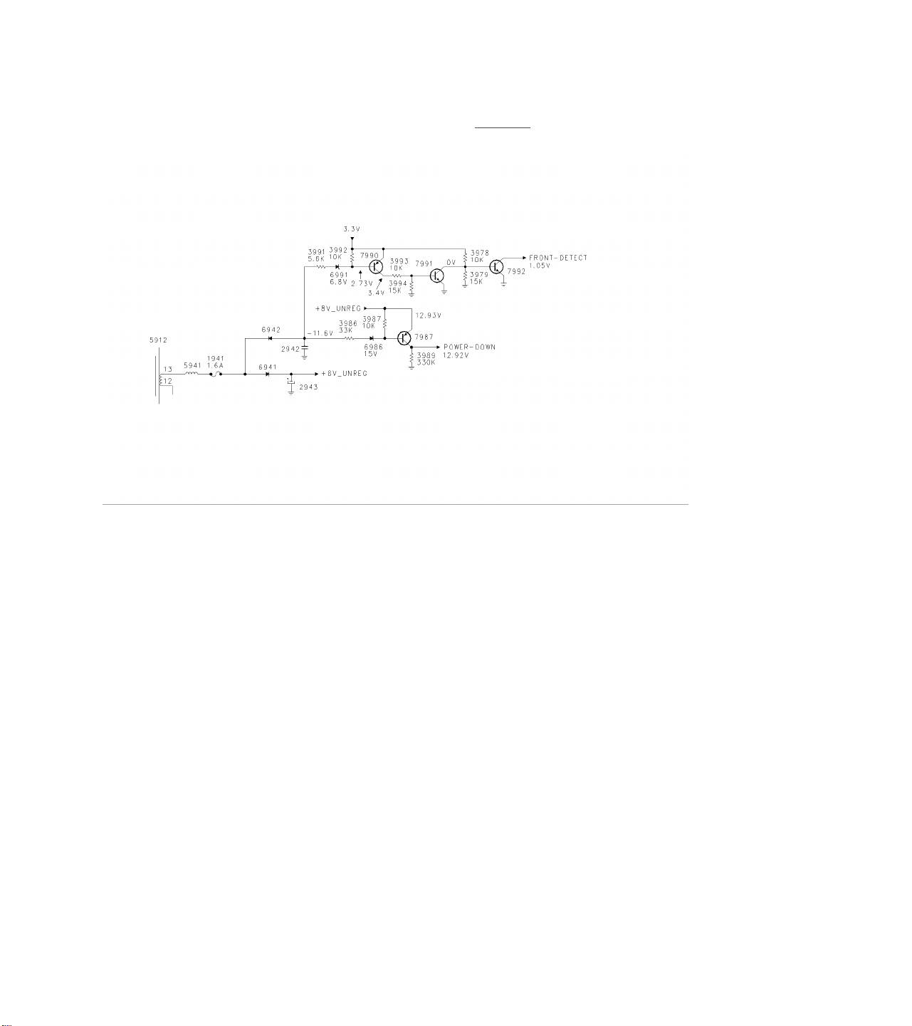
Power Down and Front Detect Figure 4
The Power-Down and Front Detect circuits signal the Microprocessor in case power is removed from the set.
The Microprocessor will store the customer settings before shutting the set down. Diode 6942 produces a
negative voltage to turn transistor 7987 On, keeping the Power-Down line High. This keeps transistor 7277
turned Off. If power is removed from the set, the negative voltage will discharge before the operating voltage for
the set falls. Transistor 7987 will turn Off. 7277 will then turn On, placing a High on the RGB CRT drive lines,
blanking the CRT. Transistor 7277 will continue to conduct until Capacitor 2284 has discharged. In the same
manner, 7990 will be turned Off, turning 7991 Off, which will turn 7992 On, causing the Front-Detect line to go
Low. This will prevent the Microprocessor from receiving any commands while the set is being shut down. If
there is a problem in this circuit which causes the Front Detect line to go Low, the Microprocessor will not
respond to any commands from the Keyboard or Remote.
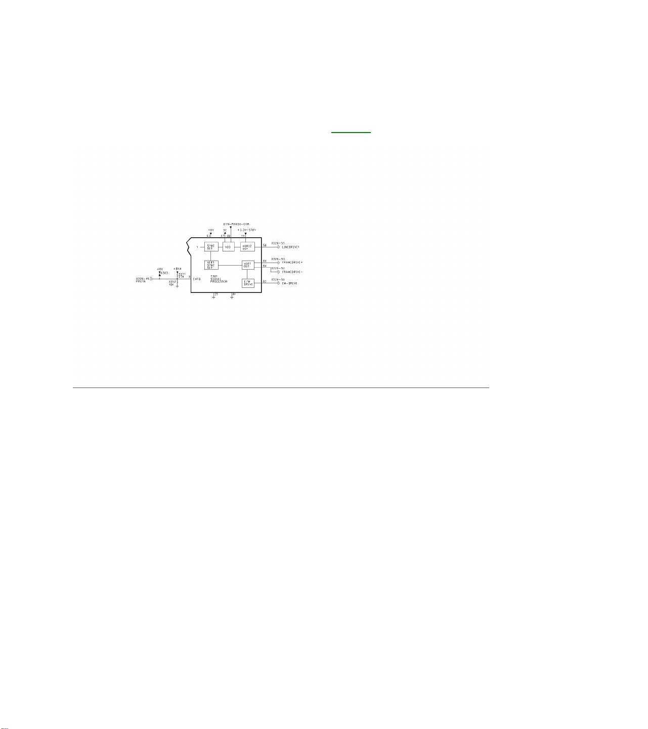
SWEEP AND SHUTDOWN CIRCUITS
Horizontal and Vertical Drive Figure 5
The 3.3 volts Standby supply provides power to 7301 on Pin 14 for a Horizontal Soft Start. The Standby line
from the Microprocessor turns the +8 volt supply On to provide power for the Sync circuits when the set is
turned On. The Horizontal Output on Pin 56 is switched On by the Microprocessor via the I2C buss, after the
Soft Start is complete. Vertical Drive, labeled Frame-Drive, is output on Pins 63 and 64. In the event the
Vertical Output should fail, the Signal Processor 7301 will blank the RGB output. East-West Drive on Pin 62
provides linearity correction for the Very Flat and Larger CRTs. Sandcastle is output on Pin 57. The Dynamic
Phase Correction input on Pin 58 has two functions. One function is to provide Horizontal Phase correction for
the Horizontal Drive. The other is to provide Flash protection in case of an overvoltage on the I-Beam line. If
the pulse on Pin 58 exceeds 6 volts, Horizontal Drive will be shut Off. It will be necessary to recycle power to
the set to restore operation. This failure will generate an error code 1 indicating a problem with the Horizontal
Output Transformer or with the CRT drive circuit. The PROTN line is connected to the IBEAM (Dag) line. This
voltage is used to make minor adjustments in the Vertical Drive to compensate for minor changes in Beam
Current. This line is also connected to the Overvoltage Detection circuit. If this voltage exceeds 3.9 volts, the
Horizontal Drive will be shut Off. The Microprocessor will show an error code 3.
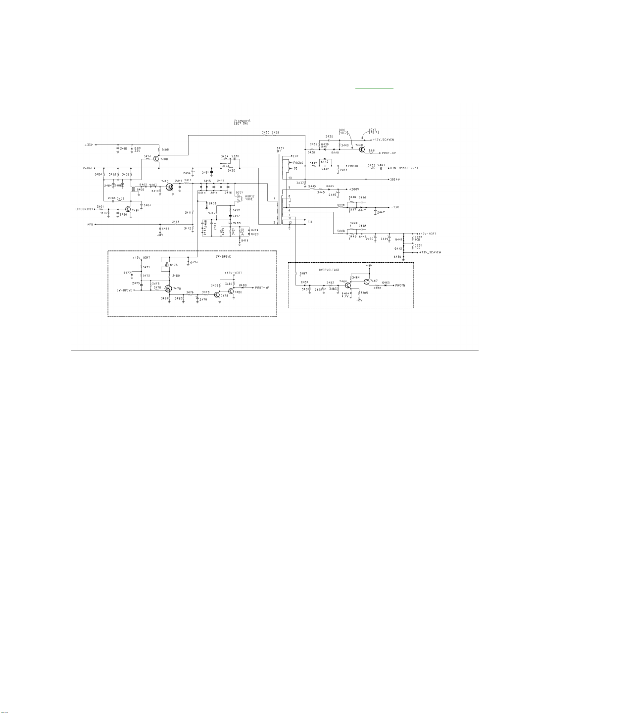
Horizontal Output and Shutdown Figure 6
Horizontal Drive (LINEDRIVE1) is fed to transistor 7481 and coupled through transformer 5406 to the Horizontal
Output transistor 7410. In sets with the Very Flat CRT and larger screen sizes, an East West Drive circuit is
present. The East West Drive circuit also has a protection circuit to detect the loss of Horizontal drive. In
normal operation, 7470 is switched by the EW-Drive. The pulse width is too narrow to develop the necessary
voltage to turn 7478 On. Current flow through 3479 keeps transistor 7480 turned On, keeping the PROT-UP
line Low. If Horizontal drive or EW Drive is lost, 7470 is turned On, applying a positive voltage to the base of
7478, turning it On. Transistor 7480 turns Off, causing the PROT-UP line to go High through resistor 3480,
which will cause the Microprocessor to turn the set Off. When the Driver Transistor 7481 is conducting, the
voltage drop across resistors 3404, 3405, and 3406 turns transistor 7408 On. This circuit supplies the 33-volt
tuning voltage and bias voltage to the IBEAM (Dag) circuit. Transistor 7440 also detects the failure of Horizontal
Drive or Overcurrent. If there is no Horizontal drive to 7481, 7408 will turn Off, removing the 33 volt tuning
voltage. Transistor 7440 will turn On, causing the PROT-UP to go High, which will cause the set to shut Off.
Voltage from Pin 5 of the IFT is rectified by 6461 and applied to 7464. If this voltage exceeds 5.4 volts, 7464
will turn On, turning 7467 On, applying the +8 volt supply to the PROTN line, shutting the set Off. The IFT
produces a plus and minus 13 volt supply for the Vertical Output circuit. The voltage on Pin 9 of the IFT is
rectified by 6445 to produce a +200 volt supply for the CRT output circuit. The Horizontal Drive signal is
sampled by 3411, 3412, and 3413 to produce the HFB (Horizontal Feedback signal) which is used to provide
Sync for the Small Signal Board.
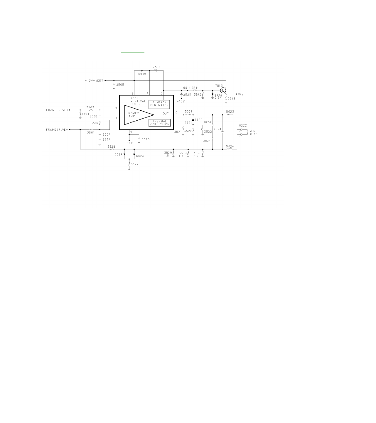
Vertical Output Figure 7
Positive and Negative Vertical drive from the Small Signal Board is fed to the Vertical Output IC7501 which
drives the Vertical Yoke. The Vertical Pulse on Pin3 drives 7513 to produce the VFB (Vertical Feedback signal)
for the Small Signal Board. A failure in the Vertical Output circuit will be detected by the Signal Processor on
the SSB by sensing the Frame Drive line and by the Microprocessor sensing the loss of the VFB pulse. While
turning the set On, check the plus and minus 13 volt sources. Then check for Vertical Drive on Pin 7 with an
oscilloscope while turning the set On.
VIDEO SIGNAL FLOW
There are four variations in the signal flow path for the H8 chassis. They are the Non-PIP, the Single Tuner
PIP, the Dual Tuner PIP, and the Double Window version.
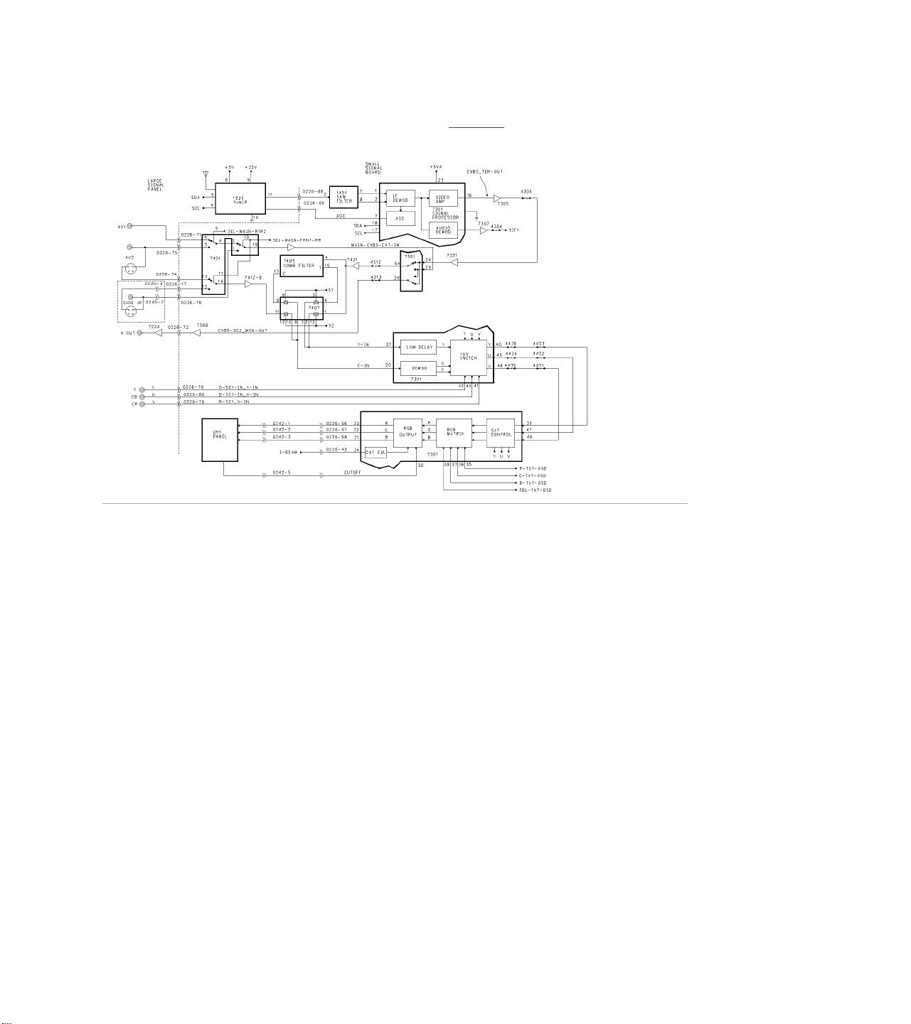
NON PIP Video Signal Flow Figure 8
The first version to be discussed is the Non PIP chassis video path. The Main Tuner, AV1, AV2, and
Component Inputs are located on the Large Signal panel. The AV3 input is located on the Side Jack Panel. All
of these inputs are fed to the Small Signal Board, SSB, which plugs into the Large Signal panel. The Tuner IF is
fed to the SAW filter, 1451, and then to the Signal Processor, 7301, on Pins 1 and 2.Composite Video is output
on Pin 16 and is buffered by 7305 and 7331. Baseband Audio is output on Pin 27 and is buffered by 7307. This
signal is fed to the Sound Decoder IC for processing. The Video Signal is then fed to 7301 on Pin 24, which
selects between the composite signal and the MAIN-CVBS-EXT-IN. The MAIN-CVBS-EXT-IN is selected
composite Video or Luminance from AV1, AV2, or AV3. These signals are selected by the Switch IC 7401
which is controlled by two lines from the Microprocessor, which are SEL-MAIN-R1R2 and SEL-MAIN-FRNTRR. If SVHS is the selected input, the Y (Luminance signal) is fed to Pin 29 by 7401. Selected Video or Y from
7301 is output on Pin 54 and is buffered by 7421. If the output of 7301 is Composite Video, the Comb Filter IC
7405 will output Y and C on Pins 15 and 13. Switching IC 7407 selects YC from either the Comb Filter or Y
from 7421. If one of the SVHS inputs is selected, 7401 outputs C (Chrominance) on Pin 14 and is buffered by
7412-B before being fed to 7407. IC 7407 is switched by Pin 22 of 7301. A High on Pin 22 causes Pins 12 and
13 to switch the inputs on Pins 1 and 11. When Pin 22 is Low, 7425 is turned Off switching Pins 5 and 6 High,
selecting the inputs on Pins 4 and 8. Selected YC is then fed to Pins 21 and 20 of 7301 where they are fed to a
Delay Line and Demodulator. The output of the Demodulator and Delay Line is fed to a YUV switch, which
selects between this signal and external YUV (Component Input) from the Jacks on the Large Signal panel.
The selected YUV signal is then fed back into 7301 on Pins 39, 47, and 48. The signal is then fed to a YUV
processing circuit and to an RGB Matrix where OSD (On Screen Display) is added. The signal is then fed to the
RGB output circuit and to the CRT. A Test Waveform is first sent to the CRT on the RGB lines. When this Test
Signal is detected by the CRT drive circuits, the signal is fed back to 7301 on Pin 3 on the CUTOFF LINE.
When these are detected, the Video signal is then output on the RGB lines.
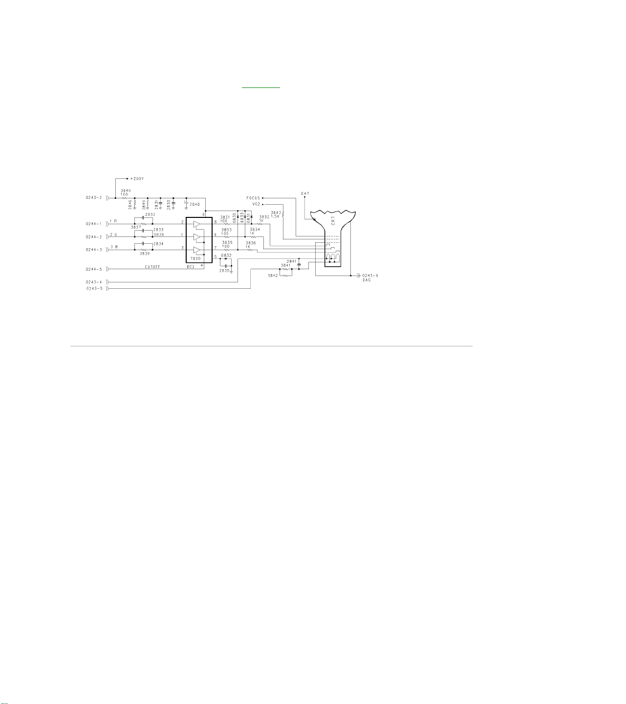
Standard CRT Drive Figure 9
The CRT drive signal is fed to 7830, which drives the CRT. As mentioned previously, a Test Signal is sent to
7830 and to the CRT. The Waveform on the left shows this Test Signal. When 7830 senses the correct current
flow in the CRT, the Test Signal is sent to the SSB via the CUTOFF line. The Picture RGB signals are then fed
to the CRT Board. This waveform is shown on the right. If the CRT is defective or unplugged, no pulse will be
output on Pin 4. Therefore, the Signal Processor IC on the SSB will not output the Video Signal on the RGB
lines.
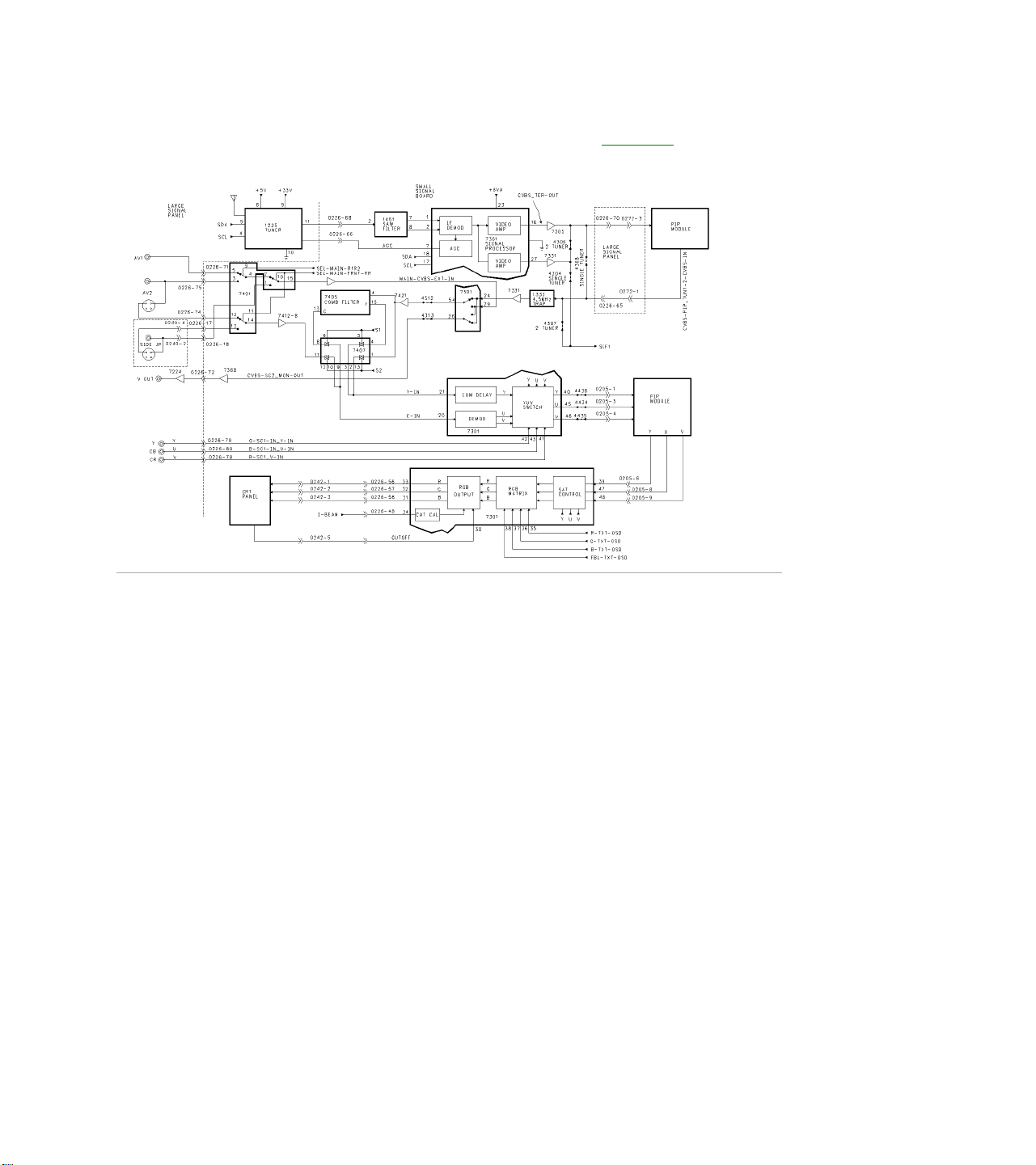
PIP (Picture in Picture) Video Flow Figure 10
There are two PIP chassis versions which are the Single Tuner and Two Tuner sets. Video Signal flow for the
Single Tuner PIP version is the same as the Two Tuner version, except the Composite Video from Pin 16 of
7301 is routed through the Large Signal Board (LSB) to the PIP module and back to the 1333 Sound Trap in the
Two Tuner version. In the Single Tuner version, Video from Pin 16 is routed through jumper 4308. The second
Tuner is located on the PIP panel. Baseband audio is output on Pin 27 and is buffered by 7331. In the TwoTuner version, the Audio is combined with the composite video before being fed to the PIP panel. Selected
Video with the Baseband Audio from the PIP panel is fed through jumper 4307 to the Audio Processor. In the
Single Tuner version, Baseband Audio from 7331 is fed through jumper 4304 to the Audio Processor. YUV
signal from Pins 40, 45, and 46 are routed through the PIP module where the PIP window Video is inserted.
Other Video signal flows are the same as for the Non-PIP version. The Single and Two Tuner PIP circuits are
the same except for the addition of the second Tuner and Signal processing circuits on the PIP panel.
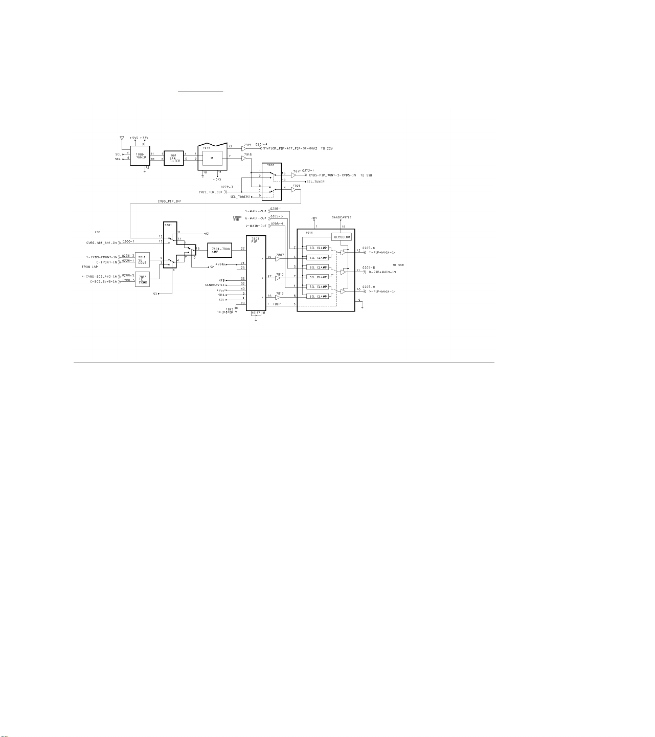
PIP Circuit Figure 11
The PIP comes in two versions, Single Tuner with no tuner on the PIP panel and two tuner versions with the
second tuner located on the PIP module. Output of the second tuner is fed to the SAW FILTER 1901, and to
the Signal Processor 7914. Composite Video is fed to the Switch 7916, which selects between the PIP tuner or
selected Composite Video from the SSB. There are two sets of switches: one to select Video for the main
picture, CVBS-PIP_TUN1-2-CVBS-IN, and one to select Video for the PIP window. Selected Video for the PIP
window is fed to 7801, which selects between the output of 7916 or from AV1, AV2, or the Side Jack panel
(labeled Front In). The output of 7801 is buffered by a four-transistor amplifier and then fed to Pin 22 of 7803,
PIP processor. The PIP processor is controlled by the I2C buss (SDA and SCL). It is kept in sync by the
Vertical sync pulse (VFB) and the Horizontal sync pulse (SANDCASTLE). The PIP window video is output as
YUV to the YUV switch 7919. The signal is combined with the main picture YUV from the SSB panel on
connector 0205. The combined YUV signal is output on Pins 12, 11, and 10 to the SSB.
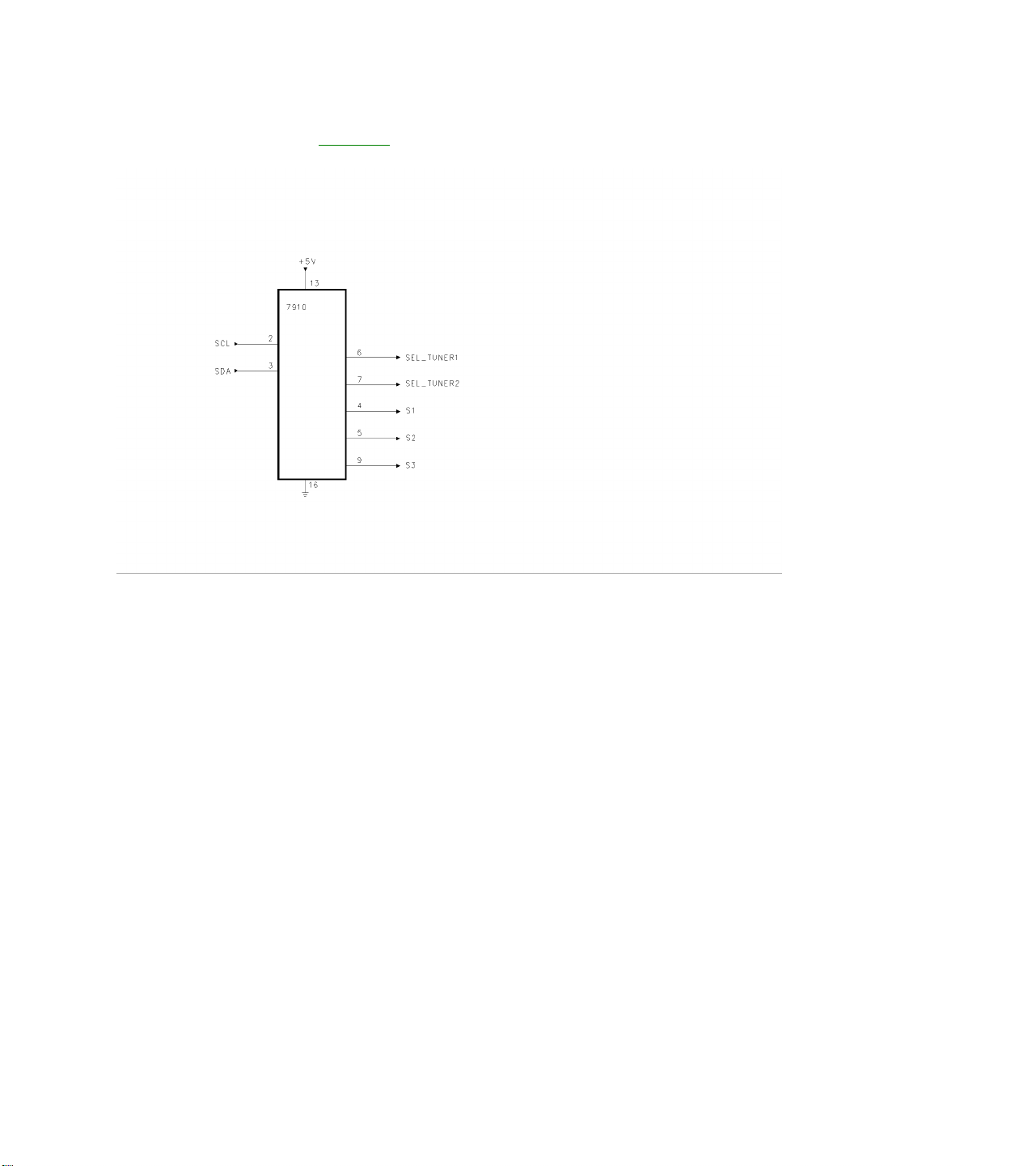
PIP Switching Figure 12
Control for the PIP panel is performed by 7910 via the I2C buss. SEL_TUNER1 and SEL_TUNER2 control the
composite switching to the SSB panel. S1, S2, and S3 control the tuner aux switching IC 7801.PIP
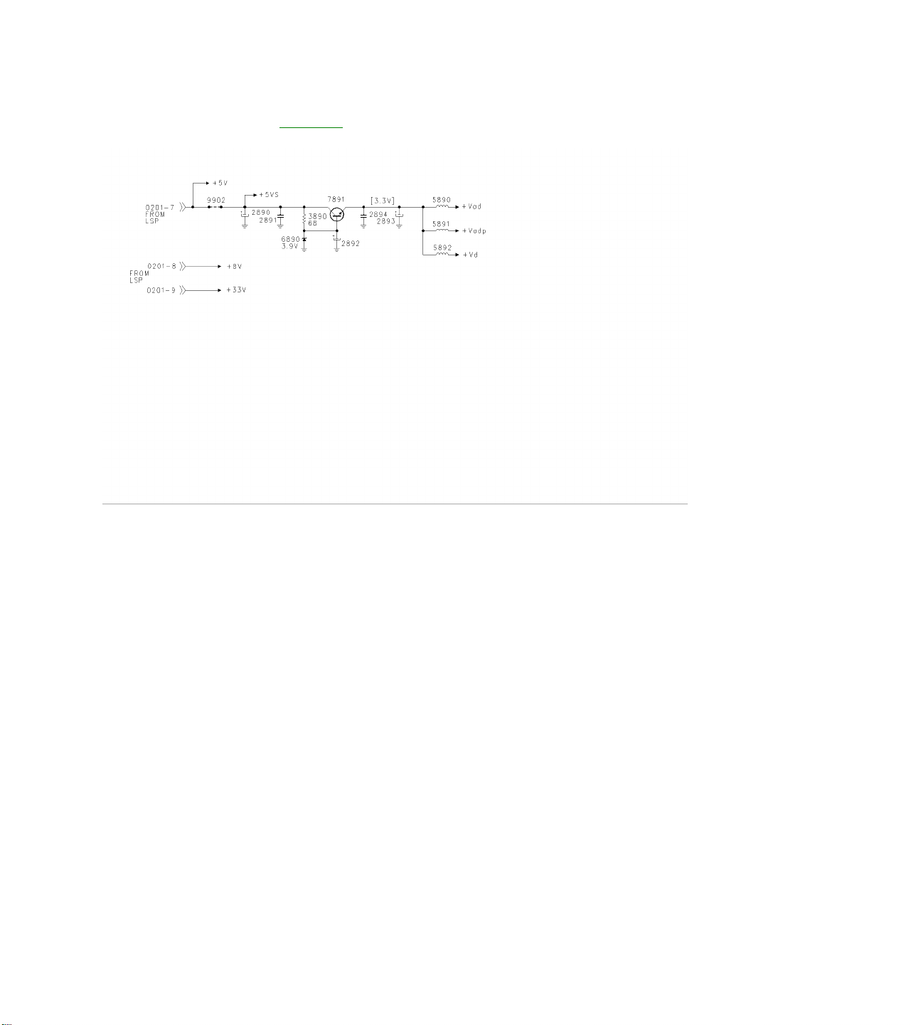
Power Supply Figure 13
The PIP panel is powered by +5 volt, +8 volt, and +33 volt supplies from the Large Signal Board (LSB). A 3.3
volt regulator supplies power to the PIP processor, 7803.
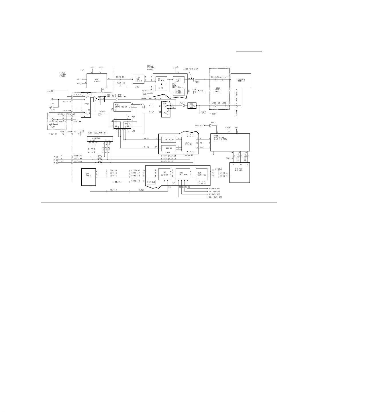
Video Signal Flow with Double Window Figure 14
The XXPT91 versions of the H8 chassis have the DOUBLE WINDOW panels. This allows for both a single PIP
window and a split screen. Each Time the PIP On/Off button on the remote is selected, the PIP window goes
from a small window to a large window and then to a split screen. Composite Video and YUV switching
between the PIP panel and the SSB is the same as the standard PIP. Two other differences are the Histogram
IC 7403 and the Gemstar module. The component YUV input is routed through the Gemstar module. If there is
a Component input to the set, such as the output of a DVD, it is combined with the on-screen Gemstar
information in the Gemstar module and output from the Gemstar module as RGB. The RGB signal is then fed
to the RGB/YUV switch in 7301. Another addition to this chassis version is the Histogram IC, 7403. The
Histogram circuit is a Contrast improvement circuit. The Y or Luminance signal is divided into 5 discrete
histogram sections for processing. Each level is adjusted to improve the overall contrast level. The Blue
Stretch circuit shifts colors near white toward Blue to give a brighter impression. The HIS-OFF is used to switch
the Histogram circuit On and Off.

Double Window Tuner and Video Switching Figure 15
The PIP/Double Window panel allows for both a standard PIP window and a split screen. The PIP/Double
Window module has a separate Tuner, SAW filter, and Signal Processor. The output of the Signal Processor,
7301, on Pin 16 is fed to switching IC 7402 which selects between the PIP Tuner and Composite Video from the
SSB for feedback to the SSB on Pin 15 or Video for the PIP window on Pin 14. IC 7401 selects Composite
Video or Luminance (Y) from AV1, AV2, or AV3. The other part of 7401 selects Chroma from the rear Jack or
the Side Jack panel. These selections are fed to 7301 on Pins 24, 29, and 20. If Composite Video is selected,
it is fed to a YC separator, then to a Delay Line and Demodulator. If it is a YC signal, it bypasses the YC
separator. The YUV signal is then fed to the YUV switch, which selects between the output of the Delay Line
and Demodulator, and external YUV from the Large Signal Board. The YUV (SY, SU, and SV) is output to the
PIP processor IC. Selected Composite Video is fed to the V-Chip processor. V-Chip processing for the main
picture is done by the Microprocessor on the SSB.
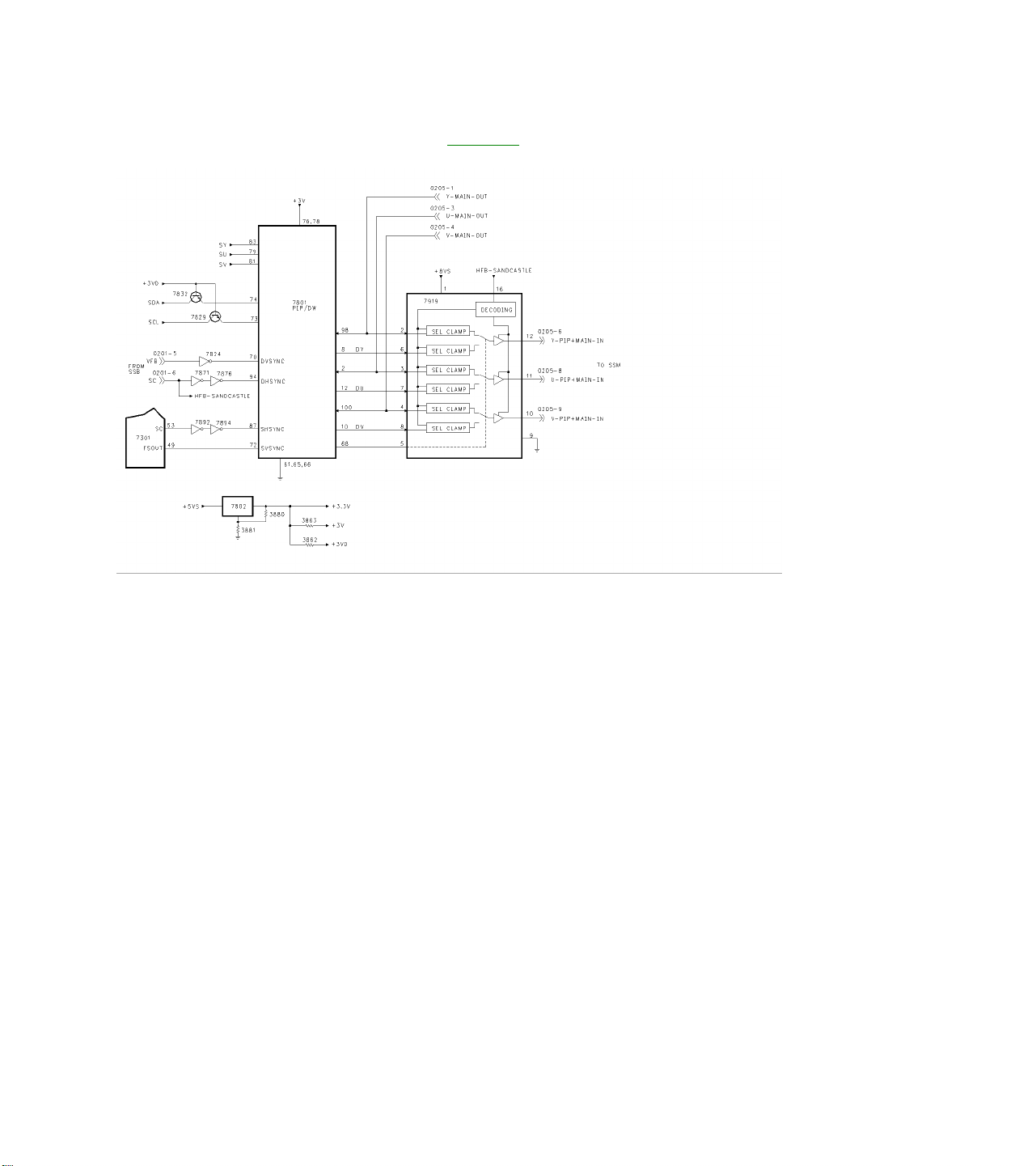
Double Window Output Figure 16
The PIP or Double Window YUV signal is fed to the PIP/DW processor, 7801. The I2C buss controls the IC
from the Microprocessor on the SSB. The PIP/DW processor outputs YUV for the PIP window or Split Screen
to the YUV switch 7803 where it is mixed with the YUV signal from the SSB for the main picture. The Fast
Blanking line from 7801 on Pin 68 controls the switch point in which the PIP window or Split Screen is inserted.
The SDA and SCL lines are switched by the +3VD line. The PIP processor is powered by the +3 volt supply.
The +3.3 volt, +3 volt, and +3VD volt supplies are produced by the regulator 7802 which is driven by the +5VS
supply. This supply is switched On when the PIP window is selected.

Double Window Control and Power Supply Figure 17
The PIP/Double Window module is controlled by the I2C buss through 7403 on the PIP module. Pins 4, 5, 6,
and 7 perform Video selection functions. Pin 10 produces a reset signal for the Guide Plus module. Pin 12
controls the +5VS and +8VS supplies.Very
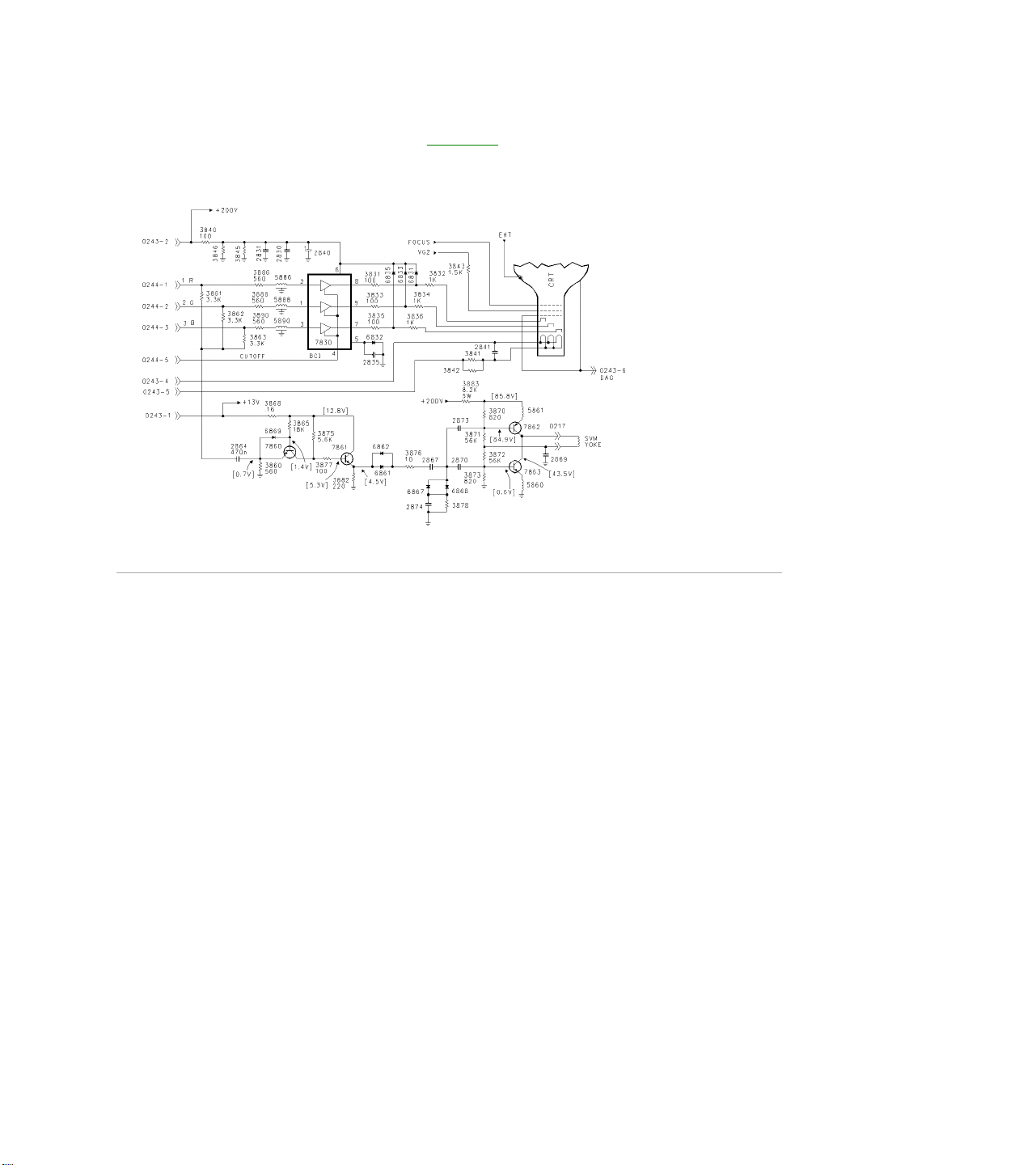
Flat CRT Drive Circuit Figure 18
The CRT panel for the Very Flat CRT's has an SVM circuit to sharpen the transitions from dark to light and light
to dark. The RGB signals are combined and fed to 7860 which performs impedance matching. The signal is
then buffered by 7861. Capacitors 2867, 2870, and 2874 along with diodes 6867 and 6868 act as a
differentiator to separate the pulses for the contrast difference. Transistors 7862 and 7863 drive the SVM yoke.
To ensure the SVM switching occurs at the correct point in the picture, delay lines 5886, 5888, and 5890 delay
the RGB signal to the RGB amplifier.
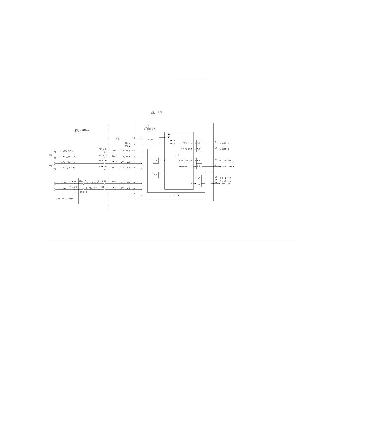
AUDIO SIGNAL PATH
Audio Signal Processing Figure 19
All Audio Processing is performed by 7651, which is located on the SSB. The Sound IF is fed to Pin 50 and to
the Sound Demodulator for decoding. The internal Switch selects between AV1, AV2, and AV3. The Audio is
digitally processed inside the IC to separate the Second Audio Program and process volume levels to maintain
a constant audio level if the user selects the AVL feature. The AUDIO-L and AUDIO-R are fed to the audio
amplifier on the Large Signal Board. The Headphone output on Pins 18 and 17 is fed to the Headphone
amplifier on the LSB. SC1_OUT-L and SC1_OUT_R on Pins 28 and 29 are fed to the monitor audio jacks on
the LSB. The AUDIO-SW, Subwoofer output, is fed to the LSB and then to the Subwoofer module. Audio
frequencies above 100 Hz are filtered out for this output. Volume levels are controlled in the Audio Processor
IC.
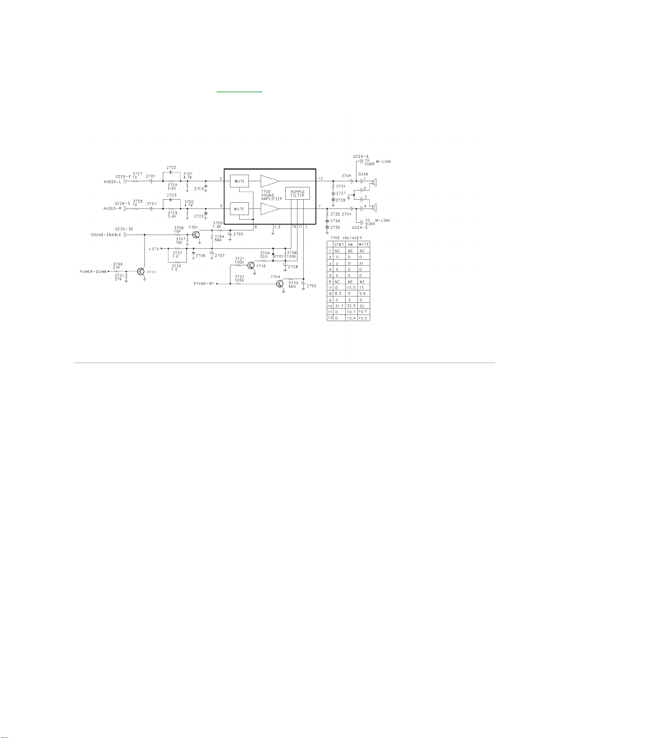
Audio Amplifier Figure 20
Audio from the SSB is fed to the Audio Amplifier on the LSB. Left Channel Audio is fed to Pin 2 of 7702 while
Right Channel Audio is fed to Pin 5. Audio is output to the speakers on Pins 12 and 7. Left and Right outputs
are also fed to the Surround Sound Speaker Jack. The output of the Surround Jacks is the difference between
the Left and Right Channels. The Amplifier is powered by a 27-volt supply, which is present, as soon as power
is applied to the set. When the set is in the Stand By mode, a High on the Stand By line turns transistors 7710
and 7704 On placing a Low on Pins 11 and 3 of 7702. This turns the output stage of 7702 Off during Stand By.
When the User selects the Mute function, the SOUND-ENABLE line goes Low, turning transistor 7701 Off. Pin
8 of 7702 will go High, muting drive to the output stage. When Sound is present, the SOUND-ENABLE line is
High. When Power is removed from the set, the POWER-DOWN line goes Low, turning transistor 7711 On,
causing the SOUND-ENABLE line to go Low. This action mutes the audio output during Power Down to prevent
a POP in the speakers.
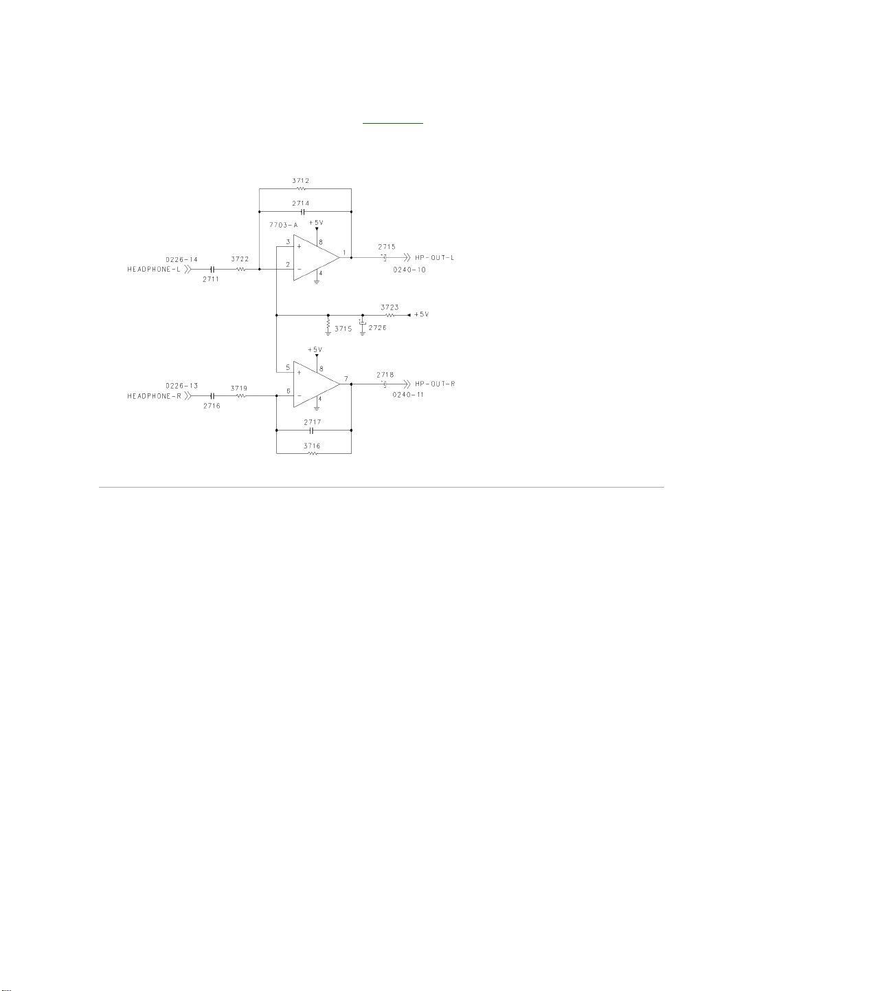
Headphone Amplifier Figure 21
Headphone audio from the SSB is fed to the Headphone Amplifier, 7703-A, located on the LSB. The Audio is
then output to the Side Jack panel. This circuit is powered by the +5 volt supply.
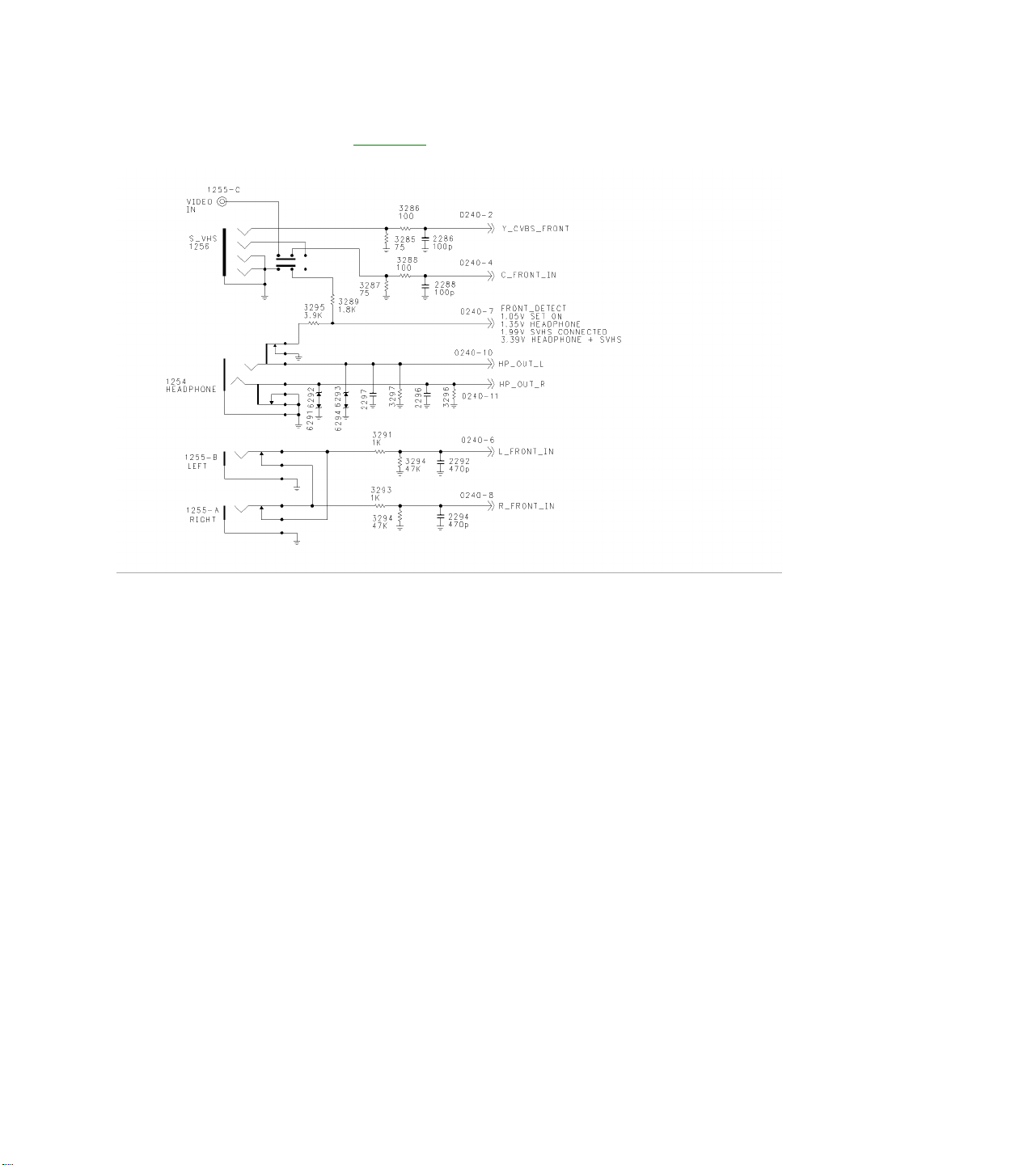
Side Jack Panel Figure 22
The Side Jack panel is the AV3 input in the Customer Menu. It has a Composite Video Input, SVHS Input, and
a Stereo Audio input. It also has a headphone output. If an SVHS connector is plugged into the Side Jack
panel, the Composite Video input is muted. The Audio inputs are designed so that if audio is plugged into only
one input, the signal will be fed to both the Left and Right Channel lines. The Front Detect line tells the
Microprocessor if an SVHS or Headphone is connected to the Side Jack panel. In normal operation, the
FRONT-DETECT line is approximately 1.05 volt. When a Headphone is plugged in, resistor 3295 is taken out
of the circuit causing the voltage to increase to 1.35 volts. The Microprocessor will activate the Mute line. With
only the SVHS connected, resistor 3289 is out of the circuit, causing the FRONT-DETECT line to increase to
1.99 volts. An indicator will appear in the Menu to indicate that SVHS is present on AV3. With both a SVHS
and Headphone connected to the Side Jack panel, both resistors are out of the circuit and the voltage will
increase to 3.39 volts. This will give the SVHS indication in the Menu and Mute the Audio. If the Side Jack
panel is disconnected while troubleshooting the set, the Audio will be muted.
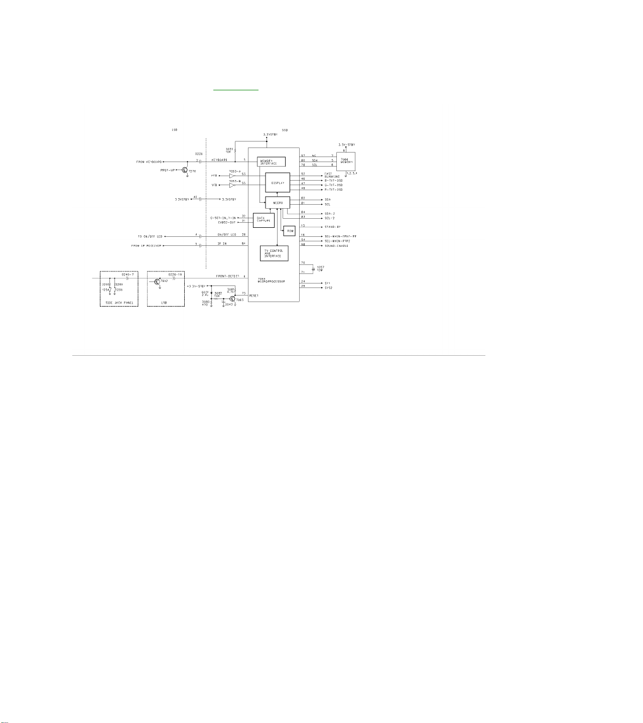
Microprocessor Figure 23
The Microprocessor, 7064, is located on the SSB. User control of the Microprocessor is accomplished via the
Keyboard or Remote. In case of Overcurrent or a failure in the Horizontal sweep circuit, The PROT-UP line will
go High turning transistor 7276 On, placing a Low on Pin 5 of the Keyboard line. The Microprocessor will then
shut the set Off. Composite Video for Data capture, for Closed Caption or Text, is fed to the IC on Pins 32 and
31. The Microprocessor is connected to the Memory IC 7066, which stores information for Option Codes,
Geometry, Gray Scale, and Customer settings. Two I2C busses, SDA and SDA-2, communicate with the set
along with several analog outputs. The set is turned On when the STAND BY line on Pin 13 is pulled Low by
7064. Horizontal and Vertical sync for the On-Screen display is fed to the IC on Pins 53 and 55. The Reset for
the Microprocessor is located on the SSB. Transistor 7063 turns Off as 2043 charges causing Pin 73 to go High
when power is first applied to the set for Reset. When the set is operating normally, the Reset pin should
measure Low. The FRONT-DETECT line monitors the Side Jack panel for the Headphone or an SVHS
connection. It also monitors 7992 for a Power Down. A Low on Pin 6 will disable the Keyboard and IR inputs.
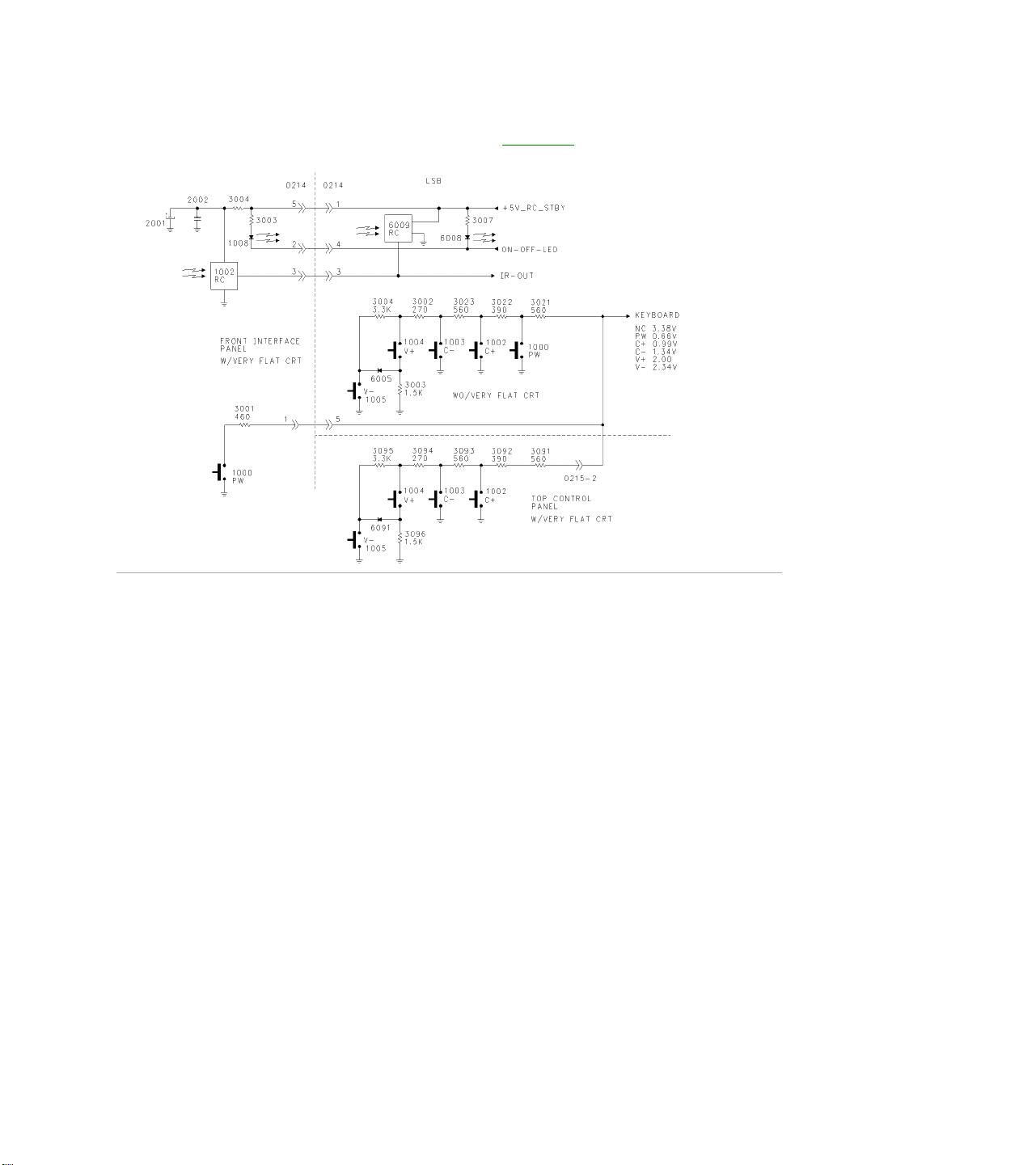
Customer Control Interface Figure 24
The Keyboard line is a voltage level controlled input. With no buttons pressed, this line should read
approximately 3.38 volts when the set is On. It will be approximately 0.2 volts higher when the set is in Standby.
In the XXPT31 versions, the Keyboard Switches are located on the LSB. In the XXPT41 and above models, the
Keyboard Switches are located on the Top Control panel for Volume Down, Volume Up, Channel Up, and
Channel Down. The Power Switch is located on the Front Interface panel.

SERVICE MODES
All of the adjustments in the set are performed via the On-Screen Service mode. There are three different
Service Modes. The SDM (Service Default Mode) allows Error Codes to be read through an On-Screen menu
or from a blinking Power light. It also pre-sets certain conditions and disables certain functions. The next
Service mode is the SAM (Service Adjustment Mode). This mode is used to align the set, adjust option settings,
and read and clear the error buffer. The final mode is the CSM (Customer Service Mode). This mode can be
entered by the Customer on instruction of the Service Technician to read error codes. Service Default Mode
(SDM)The Service Default Mode can be entered by pressing 0-6-2-5-9-6-Menu, on the remote control
transmitter. The Service Default Mode sets the following conditions:
Tuning Frequency is set to 61.25 MHz (Channel 3).
Volume level set to 25%.
Other Picture and Sound settings set to 50%.
Timer, Sleep Timer, Parental Lock, and Blue Mute disabled.
The SDM can also be entered by shorting jumpers 9261 and 9262 while turning the set On. Caution should be
used when using this procedure because the 5-volt protection is disabled. After entering the SDM, the Error
Codes can be read by the blinking power LED. The LED will blink the number of times equal to the value of the
error codes. After the SDM has been entered, the LED will light for 750 milliseconds, followed by a pause of
1500 milliseconds, followed by the number of blinks equal to the error code. If more than one error code is
present, the procedure will repeat itself for the next Error Code. When all of the Error Codes have been
displayed, the LED will light for three seconds. The procedure will then repeat itself.
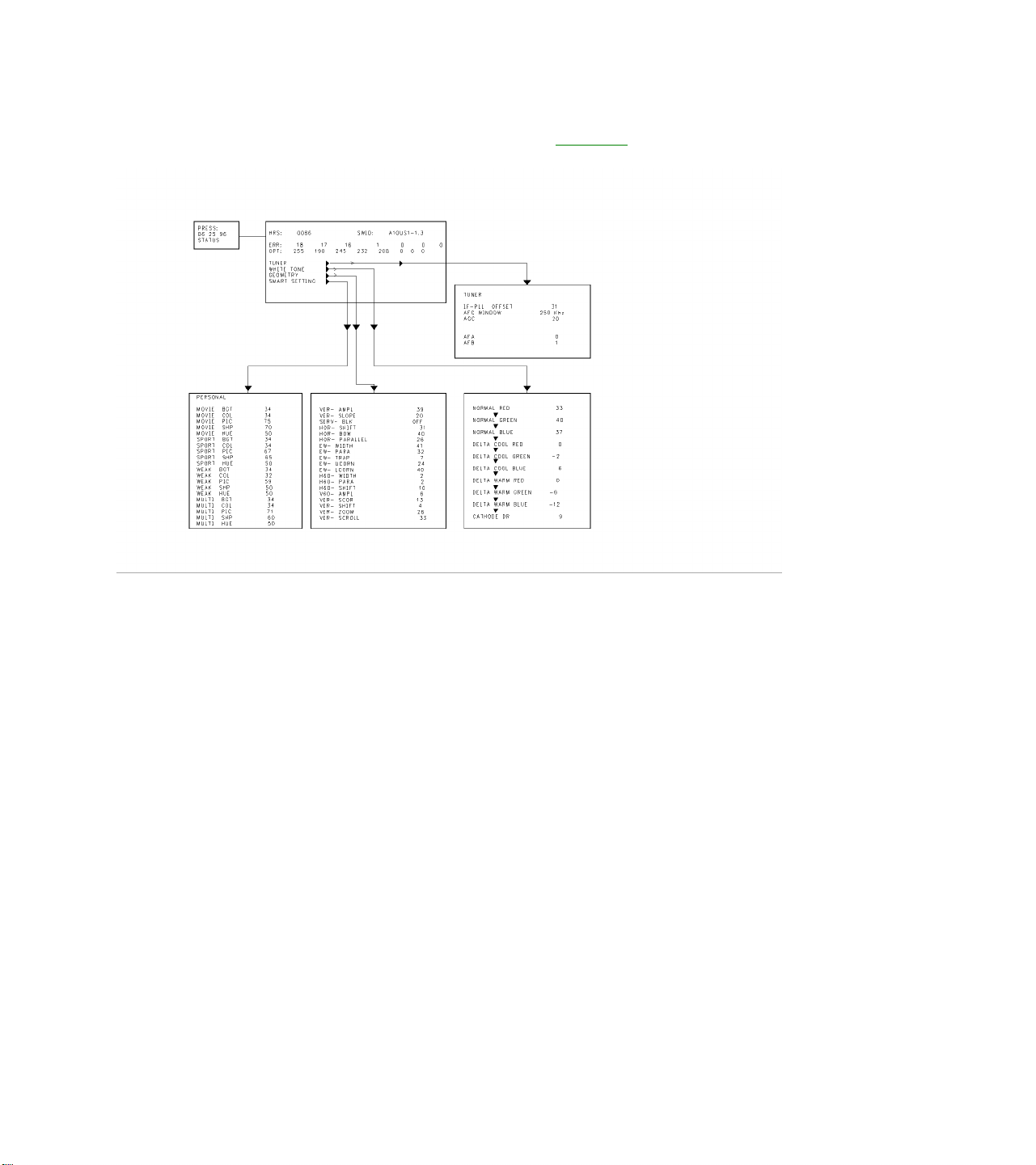
Service Alignment Mode (SAM) Figure 25
The Service Alignment Mode is used to read Error Codes, Reset Error Codes, Set Option Codes, and perform
Service Alignments. Pressing 0-6-2-5-9-6-Status on the remote control transmitter enters the SAM. To save
the Error Codes, remove AC power to the set without turning it Off. When power is reapplied and the set is
turned On, the SAM will still be active. Use the Cursor Up-Down keys to select a function in the menu. Press
the Cursor Right-Left keys to select a function or make an adjustment. Under White Tone, there are three sets
of settings which are Normal, Cool, and Warm. Normal settings are for a normal Gray Scale and should be
selected when doing a White Balance or Gray Scale adjustment. When the User selects Cool, a slight Blue tint
is added to the picture. When Warm is selected, a slight Red tint is added to the picture. Refer to the Service
Manual for the proper alignment procedure. To Save changes in SAM, return to the main menu and turn the set
Off from either the Remote Control or the Front Keyboard.
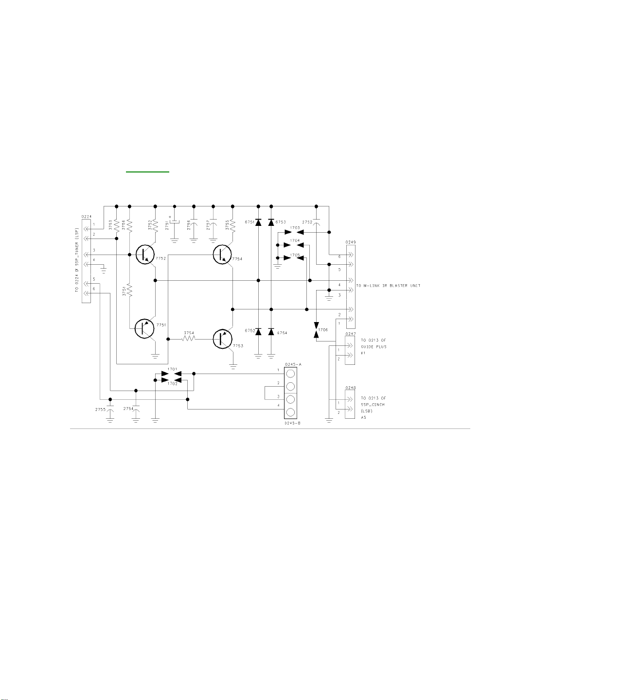
Customer Service Mode (CSM)
The Customer Service Mode allows the Customer to read the Error codes upon instruction form the Technician.
Pressing the Mute button on the Remote Control and any key on the set Keyboard at the same time can enter
the Customer Service Mode.
M-link Figure 26
The M-Link feature is on all sets above models XXPT41 and above. This feature allows external devices such
as DVD players and VCRs to be controlled by the TV set. The M-Link panel has a driver circuit, which is
connected to the I2C buss to drive the IR Blaster, which communicates with external devices. The Surround
Sound Speaker Jacks are also located on the M-Link panel.
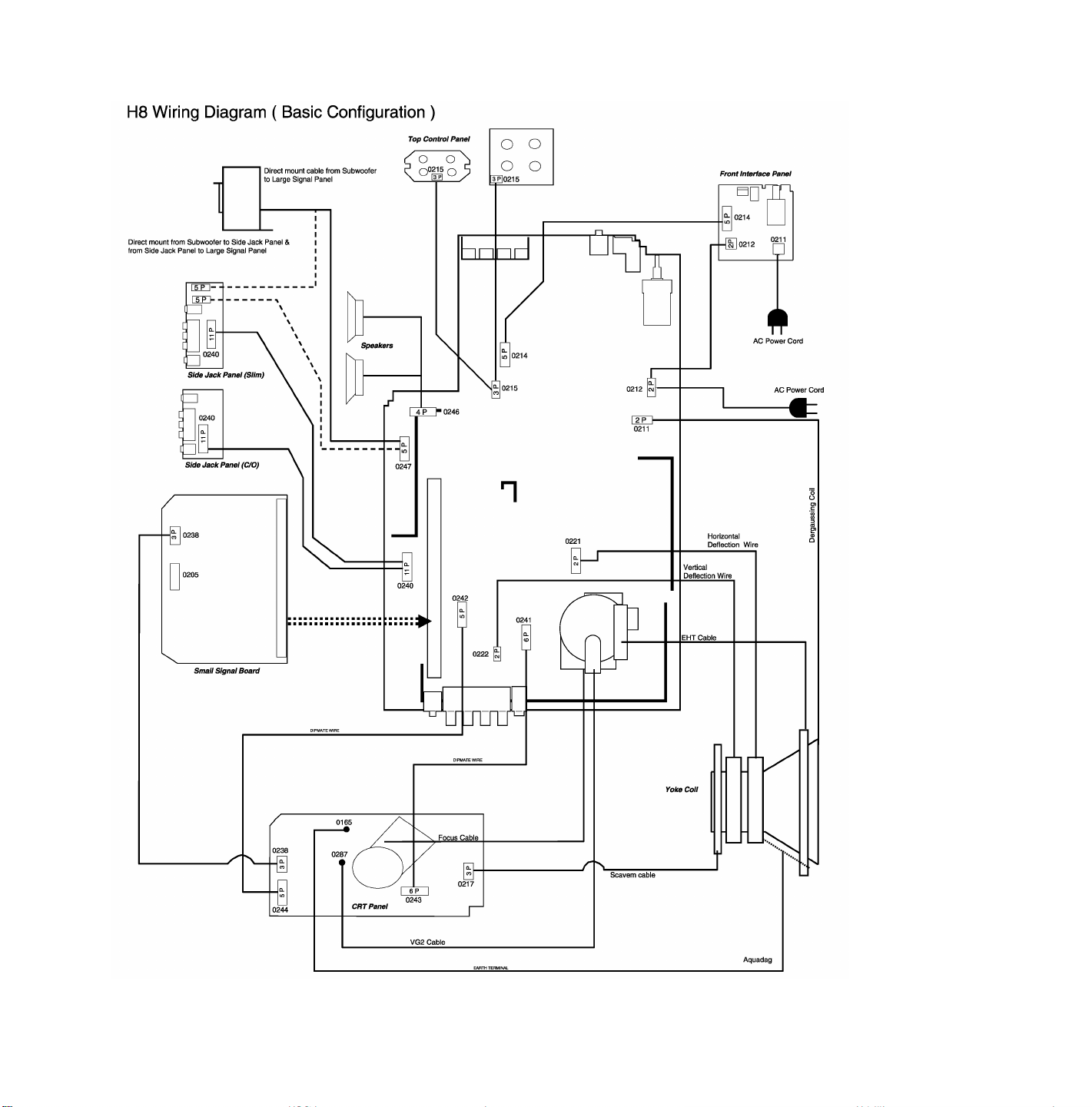
Wiring Diagrams
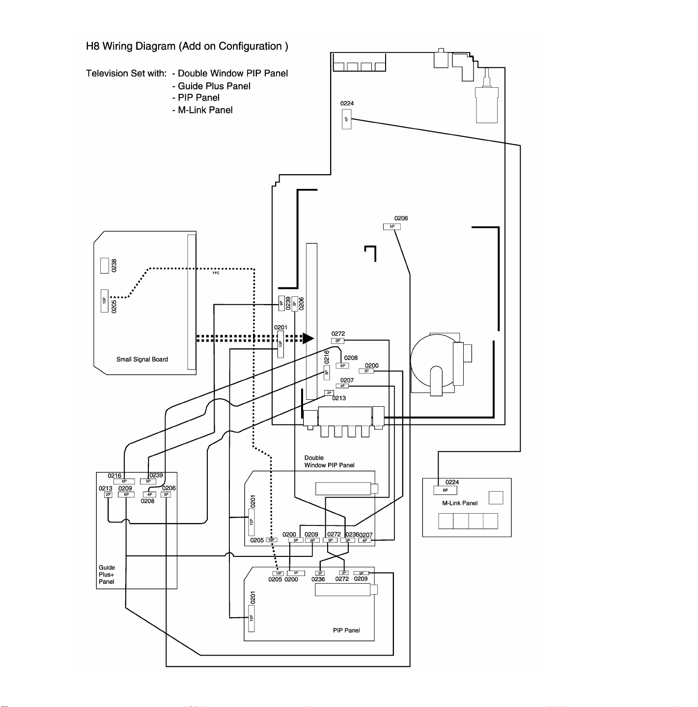
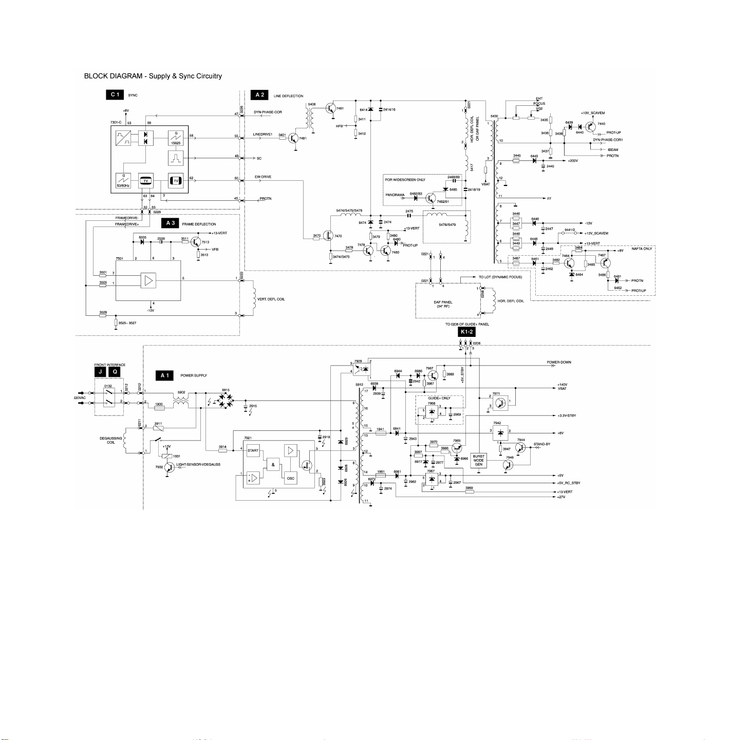
Block Diagrams
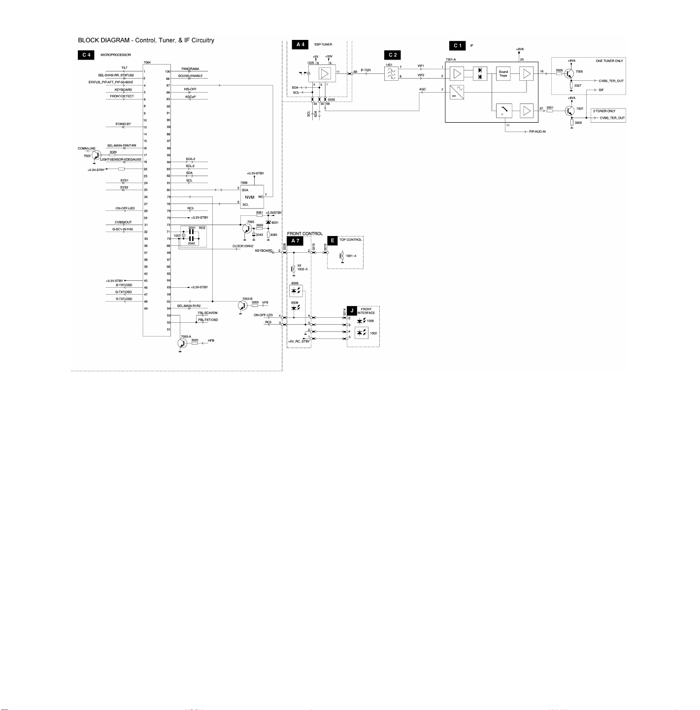
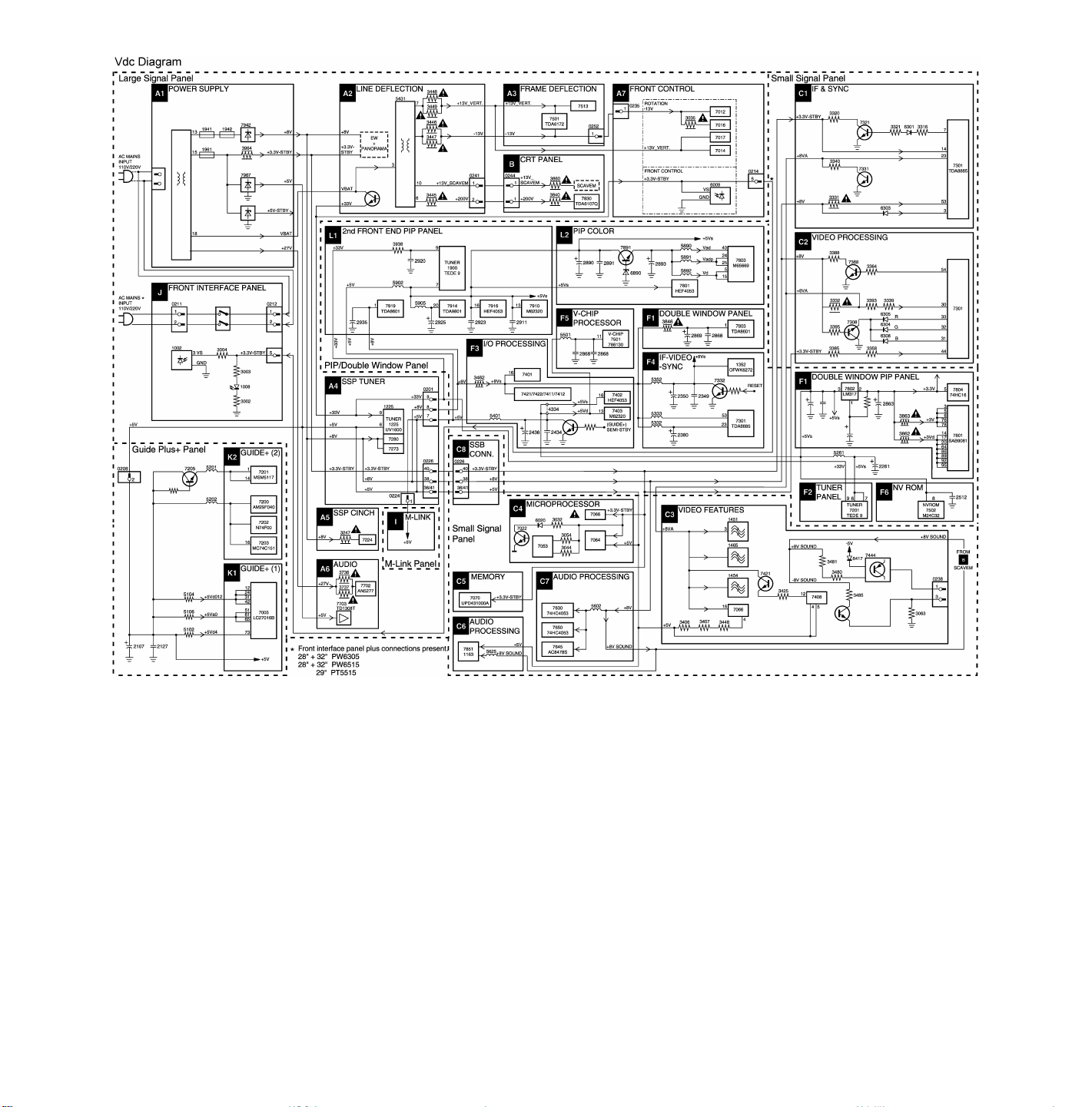

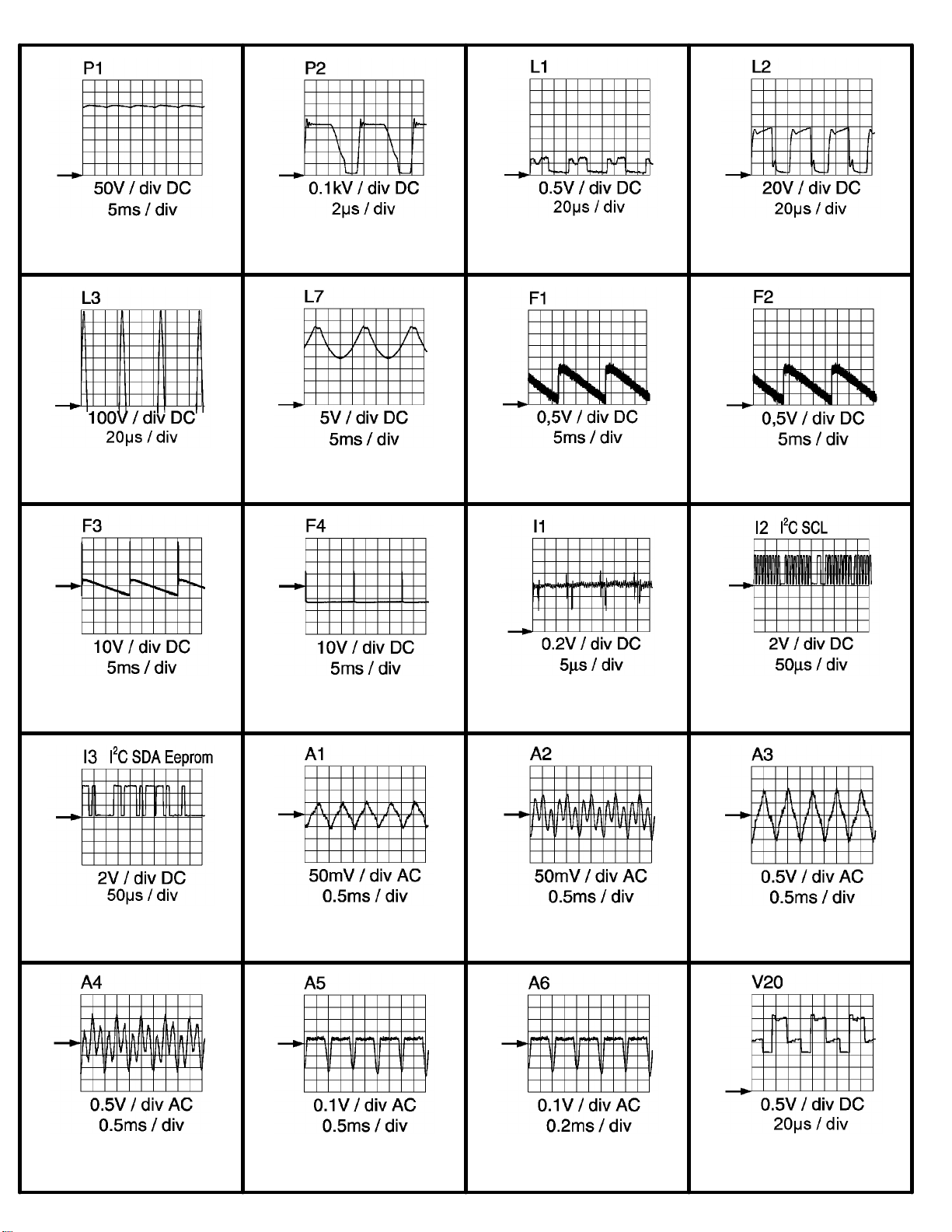
27H8(7592)
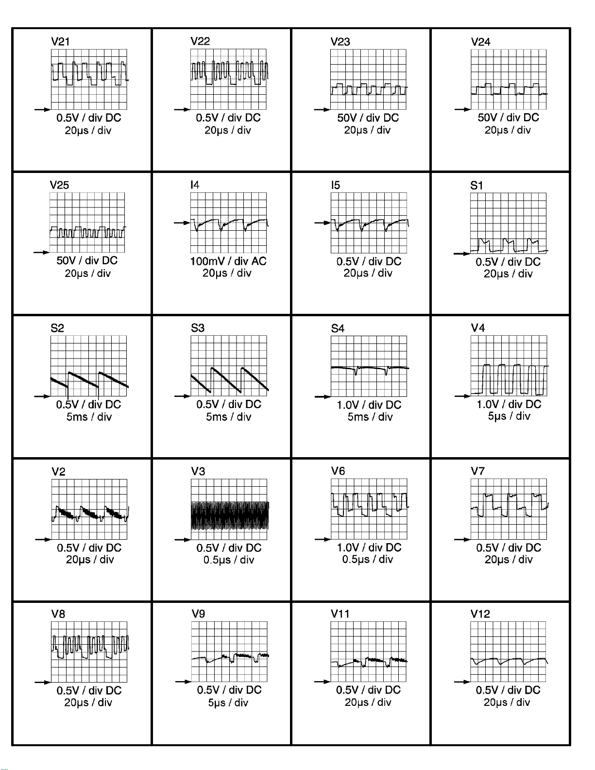
27H8(7592)
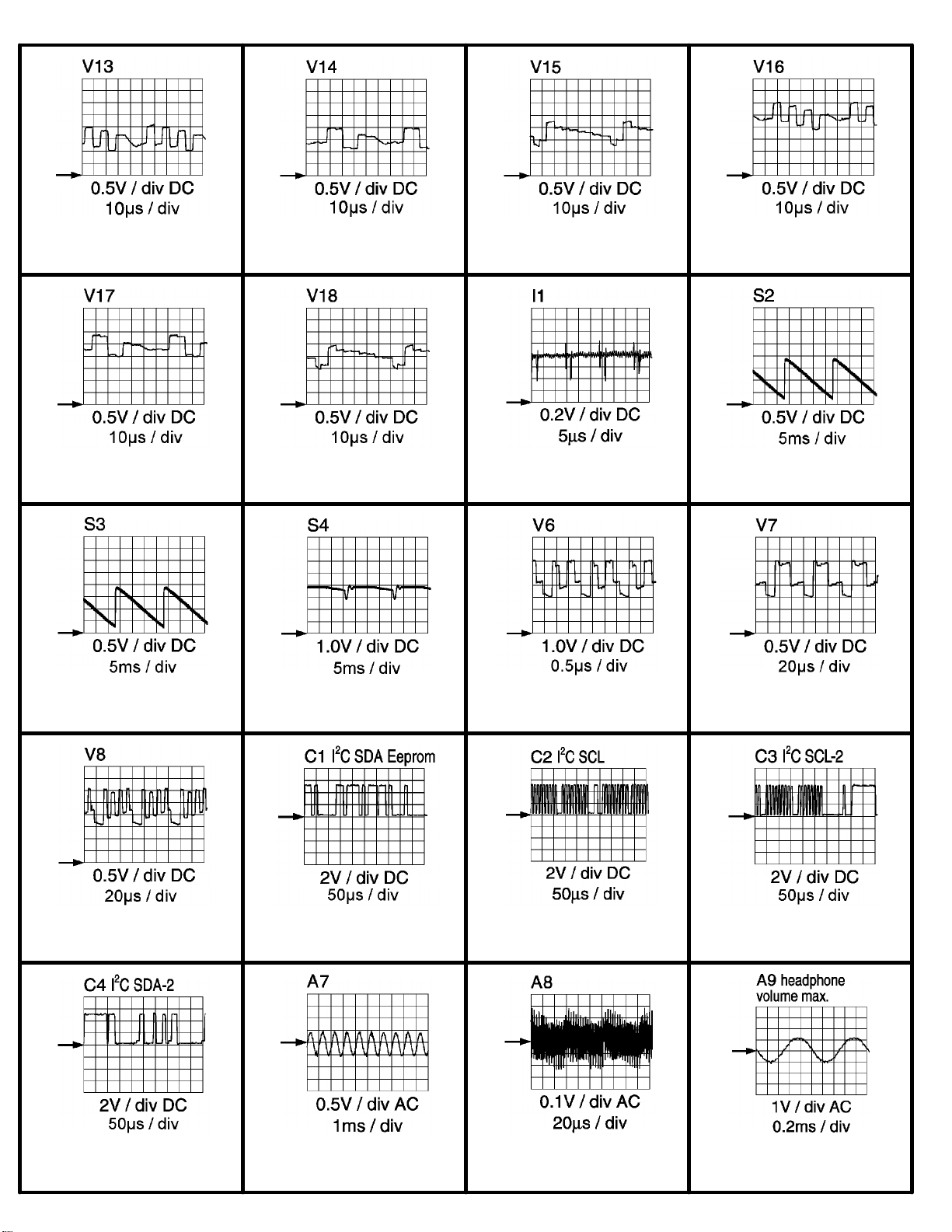
27H8(7592)
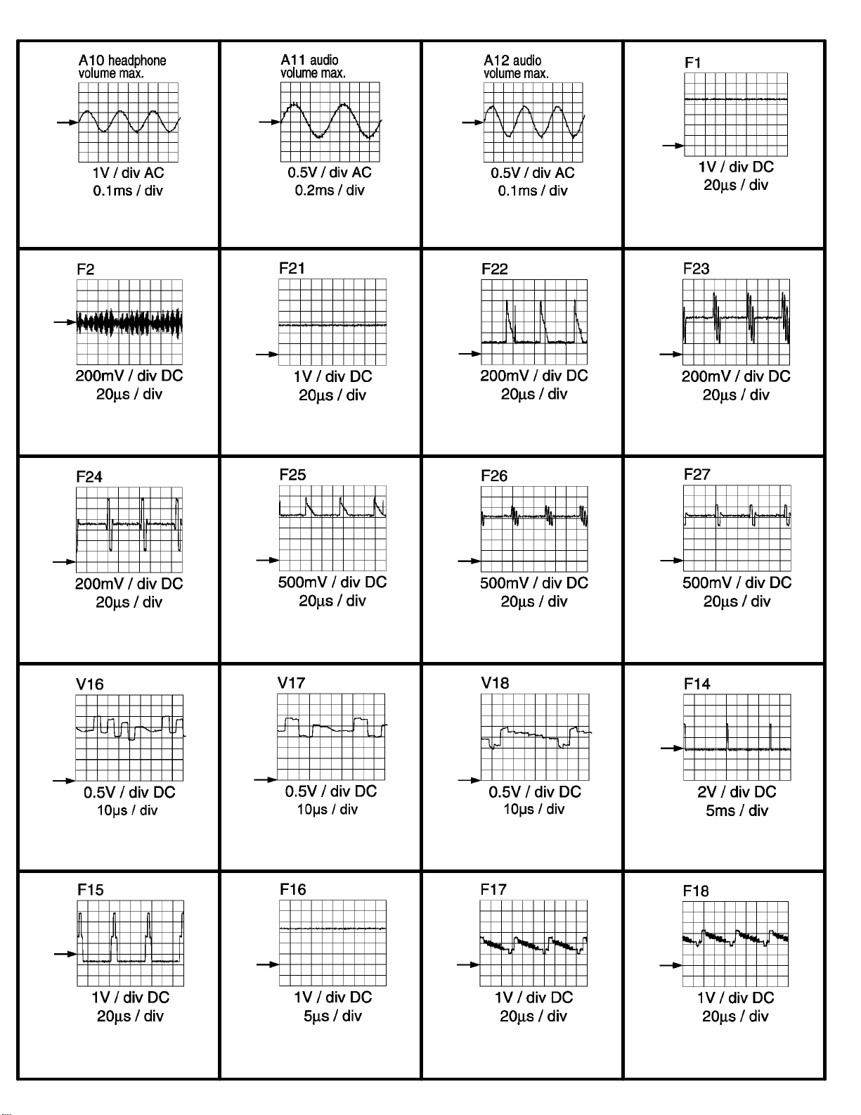
27H8(7592)
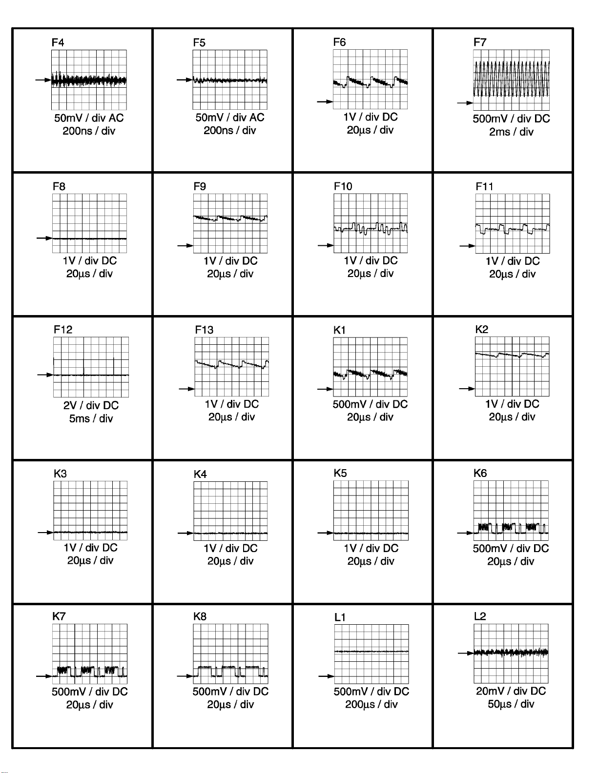
27H8(7592)
 Loading...