

Page 1
PHILIPS
CONSUMER ELECTRONICS
PHILIPS
o'oaaaoa оооззо
AUDIO/VIDEO SYSTEM
SYSTEME AUDIO/VIDEO
AUDIO/VIDEO SYSTEEM
SISTEMA AUDIO/VIDEO
Page 2

Page 3
Page 4

English
Operating instructions
Page 1-22
Attention!
• Always open this flap page first.
Deutsch
Français
Nederlands
Italiano
Españoi
Bedienungsanleitung
Seite 23-44
Mode d’emploi
Page 45-66
Gebruiksaanwijzing
Pagina 67-87
Istruzioni per l’uso
Pagina 88-109
Instrucciones de manejo
Página. 110-131
Achtung!
• Immer zuerst dieses Umschlagblatt öffnen.
Attention!
• Commencez toujours par ouvrir ce rabat.
Attentie!
• Altijd eerst deze flap openslaan.
Attenzione!
• Aprire sempre prima questa pagina pieghevole.
Atençâo!
• Abra simpre em primeiro lugar esta página desdobrável.
Page 5

Information for users in the UK
(Not applicable outside the UK)
English
round the set for ventilation, making sure that curtains,
cupboards etc. cannot obstruct the air flow through the
ventilation apertures.
The set is intended for use in a domestic environment only and
should never be operated or stored in excessively hot or humid
atmospheres.
Service for you
Your colour television has been designed and manufactured to
the highest standards, and subject to rigorous testing. Provided
it is properly operated and maintained it will perform well for
many years. However, we ail know that in such complex
equipment components can sometimes fail.
The legal responsibility for meeting any in-guarantee service
needs for your receiver rests with the dealer from whom you
bought it. Our own Service Division - Philips Service - provides
your dealer with comprehensive technical advice, and distributes
approved spare parts from Service Centres throughout the
country. If your dealer has no service facilities, he can arrange
for any work to be carried out by a competent third party
organisation.
In any event you may expect speedy attention to restore your set
to full working order without delay.
Free service for 12 months:
The dealer from whom the receiver was purchased will arrange
for any defect in manufacture or material to be rectified without
charge for a period of 12 months from the date of initial
consumer sale provided:
• reasonable evidence is supplied that the set was purchased
within 12 months prior to the date of claim
• the defect is not due to use of the set on an incorrect voltage
or contrary to the Company’s Operating Instructions or to
accidental damage (whether in transit or otherwise); misuse;
neglect; unauthorised or inexpert modification or repair.
The picture tube guarantee is administered by Mullard Limited,
renowned manufacturer of colour picture tubes.
In addition to the customary 1 year free tube guarantee, Mullard
will extend the guarantee period by a further 3 years for a
nominal fee.
To register your tube guarantee please send:
a) your name and address;
b) your set’s identity card (which will be returned to you);
c) a cheque/p.o. made out to ‘Mullard Ltd’ for £ 15.00 if you wish
to extend your 1 year by a further 3 years;
to the following address:
Mullard Limited
Service Department
Free Post
Beddington Lane
Croydon CR9 9AU
Service after 12 months;
Continuing service after 12 months is available in the same way
but the service will be chargeable.
These statements do not affect your statutory rights as a
consumer.
If you have any question which your dealer cannot answer,
please write to:
C.E. Consumer Relations Department
P.O. Box 298
420 London Road
Croydon CR9 3QR
All enquiries and claims can be handled more efficiently if
accompanied by the Identity Card printed on the back cover of
this booklet - this is provided for your reference and should be
kept In a safe place.
Positioning the TV
For the best results, choose a position where light does not fall
directly on the screen, and at some distance away from radiators
or other sources of heat. Leave a space of no less than 3 cm all
Fitting the stand (if provided)
Use only the stand provided with the set, making sure that the
fixings are properly tightened. A diagram showing how to
assemble the stand is packed in the castor bag. Never use a
make-shift stand, or legs fixed with woodscrews.
Mains connection
Before connecting the TV set to the mains, check that the mains
supply voltage corresponds to the voltage printed on the type
plate on the rear panel of the TV. If the mains voltage is different,
consult your dealer.
Important
The wires in the mains lead are coloured according to the
following code.
BLUE = NEUTRAL
BROWN = LIVE
If the mains plug (or adaptor) contains a fuse, the value of this
fusé should be 3 amp. Alternatively, if another type of plug (not
fused), is used, the fuse at the distribution board should not be
greater than 5 Amp.
If the colours of the wires in the mains lead do not correspond
with the coloured markings identifying the terminals in your plug,
proceed as follows:
The BLUE wire should be connected to the terminal marked ’N’
or coloured black.
The BROWN wire should be connected to the terminal marked
’L’ or coloured red. Before replacing the plug cover, make
certain that the cord grip is clamped over the sheath of the lead
- not simply over the two wires.
Connecting the aerial
The aerial should be connected to the socket marked nr at the
back of the set. An inferior aerial is likely to result in a poor,
perhaps unstable picture with ghost images and lack of contrast.
Make-shift loft or set-top aerials are often inadequate. Your
dealer will know from experience the most suitable type for your
locality.
Should you wish to use the set in conjunction with other
equipment, which connects to the aerial socket such as TV
games, or a video camera it is recommended that these be
connected via a combiner unit to avoid repeated connection and
disconnection of the aerial plug.
General Points
Please take note of the section ‘General’ at the end of the
English section in this booklet.
Interference
The Department of Trade and Industry operates a Radio
Investigation Service to help TV licence holders improve
reception of BBC and IBA programmes where these are being
spoilt by interference. If your dealer cannot help, ask at a main
Post Office for the booklet ‘Howto Improve Television and Radio
Reception’.
Stereo TV sound
At present there are no TV broadcasts in the UK with stereo
sound. TV sets with stereo sound facilities will reproduce stereo
sound from suitable external sources connected via the
Euroconnector socket, eg. stereo Video Recorder replaying
pre-recorded material.
Page 6
Introduction
Installation
In these operating instructions you will
find all the functions and facilities of the
monitor, audio/video tuner amplifier
and remote control.
The remote control is multifunctional
and is for use with suitable Philips
audio/video equipment.
The monitor has a facility for displaying
information on the screen, known as
On Screen Display (OSD).
For optimum sound reproduction it is
advisable to use the specially designed
loudspeaker boxes.
The easiest way of learning to use the
monitor, A/V tuner amplifier and remote
control is to carry out the operations
described below in the order indicated.
Important
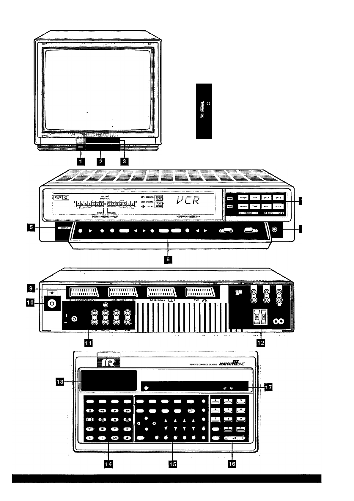
The drawings which accompany these
instructions each have a number, e.g.
n. These numbers refer to the same
numbers on the fold-out page. This
makes it easier for you to find the
corresponding buttons on the monitor,
A/V tuner amplifier and remote controi.
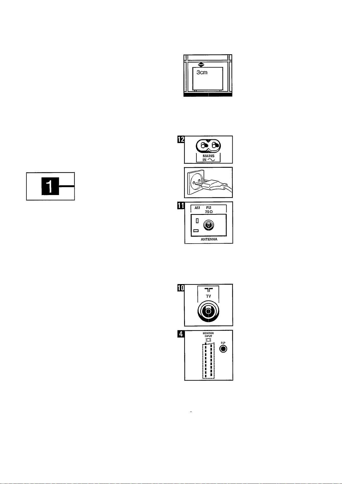
When installing the units, leave at least
3 cm free around the monitor and 5 cm
free around the A/V tuner ampiifier for
ventilation.
Do not place the monitor and A/V tuner
amplifier on a soft surface.
The monitor and A/V tuner amplifier are
suitable for a mains voltage of 220 V. If
your mains voltage is different, consult
your dealer.
Connection
A/V tuner amplifier
• Connect the mains lead to the
MAINS IN terminal (press well home).
Monitor
• Insert the plug of the monitor and the
A/V tuner amplifier in the wall socket.
Radio antenna (FM)
Connect the antenna cable to the A/V
tuner amplifier.
Use a shieided antenna cable (COAX)
for FM radio reception and connect it to
the 75 Q. FM input.
Radio antenna (AM)
Use the AM pin terminal for AM radio
reception.
If you use your ‘own’ antenna, it should
be positioned at a distance of at least 2
metres from the audio/video tuner
amplifier.
• Connect TV antenna to input nr
(75 Q.) on the A/V tuner amplifier.
El
II II
MONITOR INPUT
• Connect the monitor, using the
Eurocabie supplied, to the A/V tuner
amplifier or terminal
MONITCR INPUT OI (monitor) and
MCNITCR INPUT DI (A/V tuner
amplifier).
Page 7
ET
m
f^flTTOR
INPUT
DI
r*-il
PIP (Picture In Picture)
• Connect the Cinch cable to the
(yellow) PIP output of the A/V tuner
amplifier and the PIP input of the
(i)
monitor.
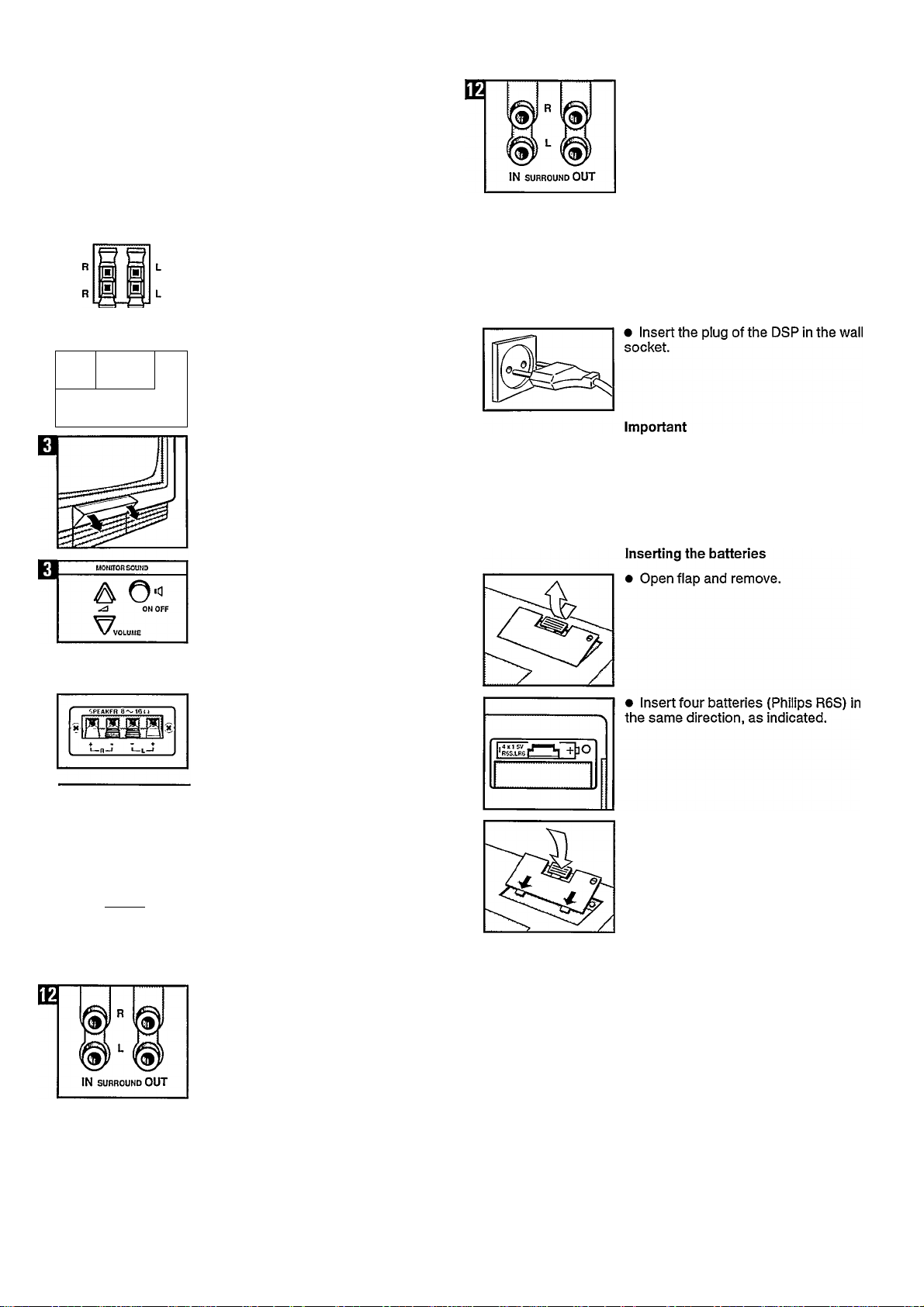
• Connect the (8 Cl) loudspeakers to
the R (RIGHT) and L (LEFT) outputs on
the A/V tuner amplifier and PIP input of
the monitor.
• Set the‘SURROUND SOUND’switch
on the A/V tuner amplifier to ON. If this
switch is in the ON position, the volume
control, volume indication, balance
control and balance indication of the
A/V tuner are switched off.
These functions and indications are
then taken over by the DSP.
The loudness and spatial stereo circuit
and the corresponding indications are
also switched off when the
‘SURROUND SOUND’ switch of the
A/V tuner amplifier is in the ON
position. These functions and
indications are also taken over by the
DSP.
m
OFF 1
SURROUND
SOUND
If no Matchline Dolby Surround
ON
Processor has been connected, the
‘SURROUND SOUND’ switch on the
A/V tuner amplifier should be in
position OFF.
Switching off built-in monitor
loudspeakers (with switched on
monitor)
• Open control panel by pressing the
top right-hand corner.
Press the IC] ON/OFF button.
Matchline Dolby Surround Processor
(DSP) 22AV1997 (if present)
• Connect two additional (8 Cl)
loudspeakers to the ‘speaker’ output of
the DSP.
• Insert the plug of the A/V tuner
amplifier in the ‘AC outlet’ of the DSP.
For further information about the
operating principle of the DSP and the
A/V tuner amplifier, see the operating
instructions of the DSP.
Remote control
• Replace flap.
SWITCHED
200W MAX
220V SO eOHz
• Now the POWER button on the DSP
simultaneously switches the DSP and
the A/V tuner amplifier ON or OFF.
• Connect the Cinch‘SURROUND
OUT’ terminal on the A/V tuner
amplifier with the Cinch ‘LINE IN’
terminal on the DSP.
• Connect the Cinch ‘SURROUND IN’
terminal on the A/V tuner amplifier with
the Cinch ‘LINE OUT’ terminal on the
DSP.
Page 8
u
^POWER^
AUDIO ^
Setting
A. Radio on the A/V tuner
amplifier
Switching on
• Press the POWER button.
Note: You can switch off the A/V tuner
amplifier by pressing the POWER
button once again.
• Press the TUNER AUDIO button (AM
or FM indication lights up).
• TU followed by a programme number
or only the frequency appears on the
display.
Control panel
• Open the flap by pressing the top
right-hand corner.
n
T DOWN UP k
i
B.
• Press the SEARCH (B) button.
AM or FM and the frequency will be
displayed, depending on where you are
searching.
If the radio station that has been
located is too weak, or if it is not the
desired station, continue to search by
pressing the SEARCH (B) button again.
Note: When a radio station has been
located, TU will flash again.
When the desired radio station has
been located, select a programme
number.
• Press the T DOWN or UP ▲ button
to select the desired programme
number.
Note: You can give 30 radio stations a
programme number (from 00 to 29).
D.
• Press the EXECUTE (D) button. The
radio station is now stored in the
memory under the programme number
selected by you.
The TU indication does not flash any
more.
Id
MODE
0
AUDIO F<P
o
SYSTEM
VIDEO
Searching for and storing radio stations
Important!
Radio stations can be found on the
medium wave (MW) and the FM band
(FM).
The MW band is indicated by AM,
frequency range 522-1611 kHz.
The FM band is indicated by FM,
frequency range 87.50-108.00 MHz.
A programme number is the number
under which you have stored a tuned-in
radio station in the memory. This is
indicated by TU and one or two digits
on the ‘audio/video selection’ display
of the A/V tuner amplifier.
Note: If the frequency is indicated, set
the A/V tuner amplifier in the
programme numbers mode by pressing
the AUDIO F/P button.
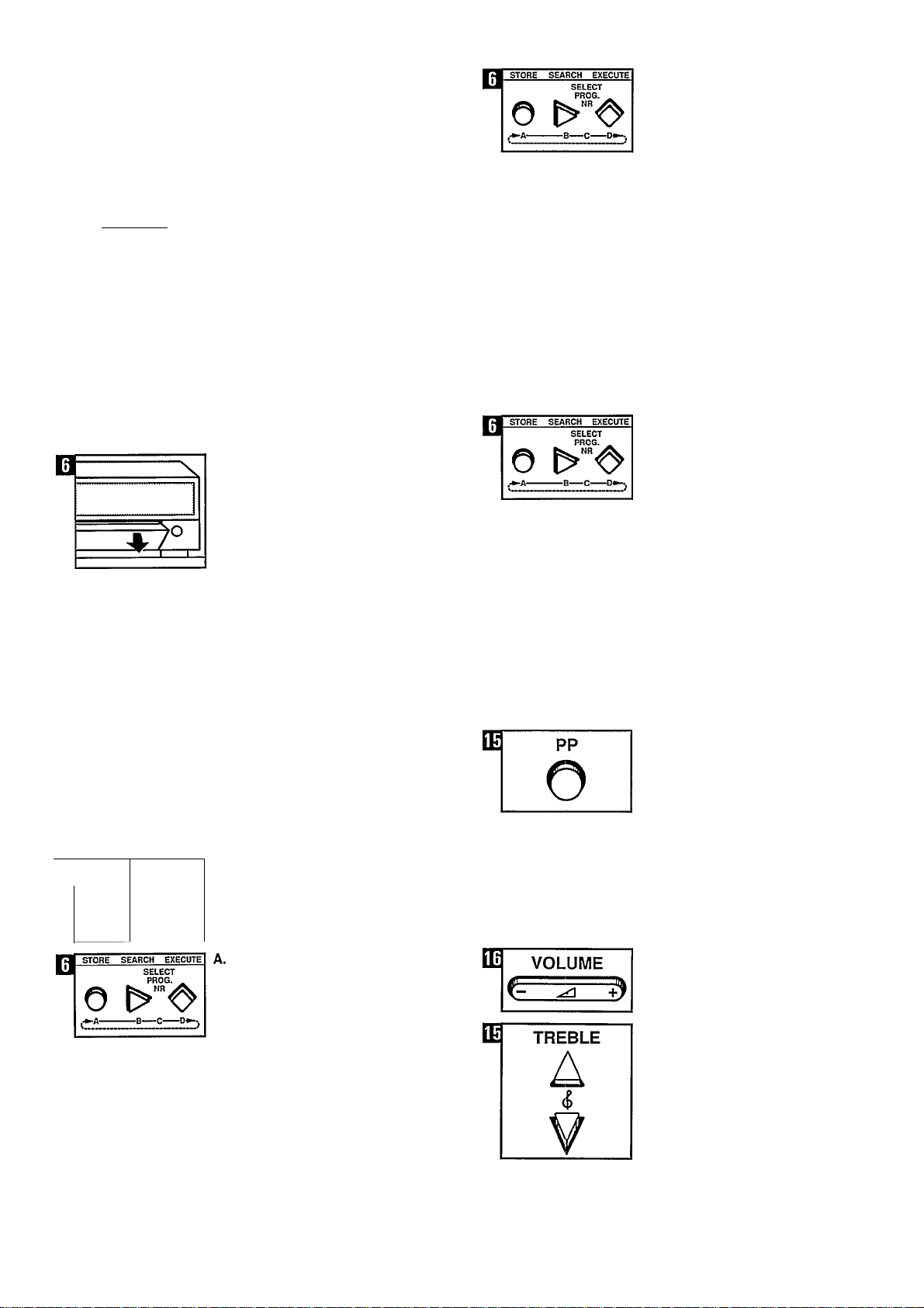
• Press the STORE (A) button.
The TU indication starts to flash.
Searching for and storing other radio stations
To search for and store the other radio
stations, repeat operations A, B, C and
D.
Personal sound setting
The sound is already stored in the
memory at a basic level.
After the sound settings have been
changed, this basic level can be reset
by pressing the green PP button on the
remote control unit.
It is possible, however, to change the
basic level according to your personal
preference and to store it in the
memory.
To do this, press the plus -F or minus
— side of the corresponding buttons
(plus at the top, minus at the bottom).
• VOLUME
High notes (5 (TREBLE),
Page 9
n
u
© POWER
VIDEO ^
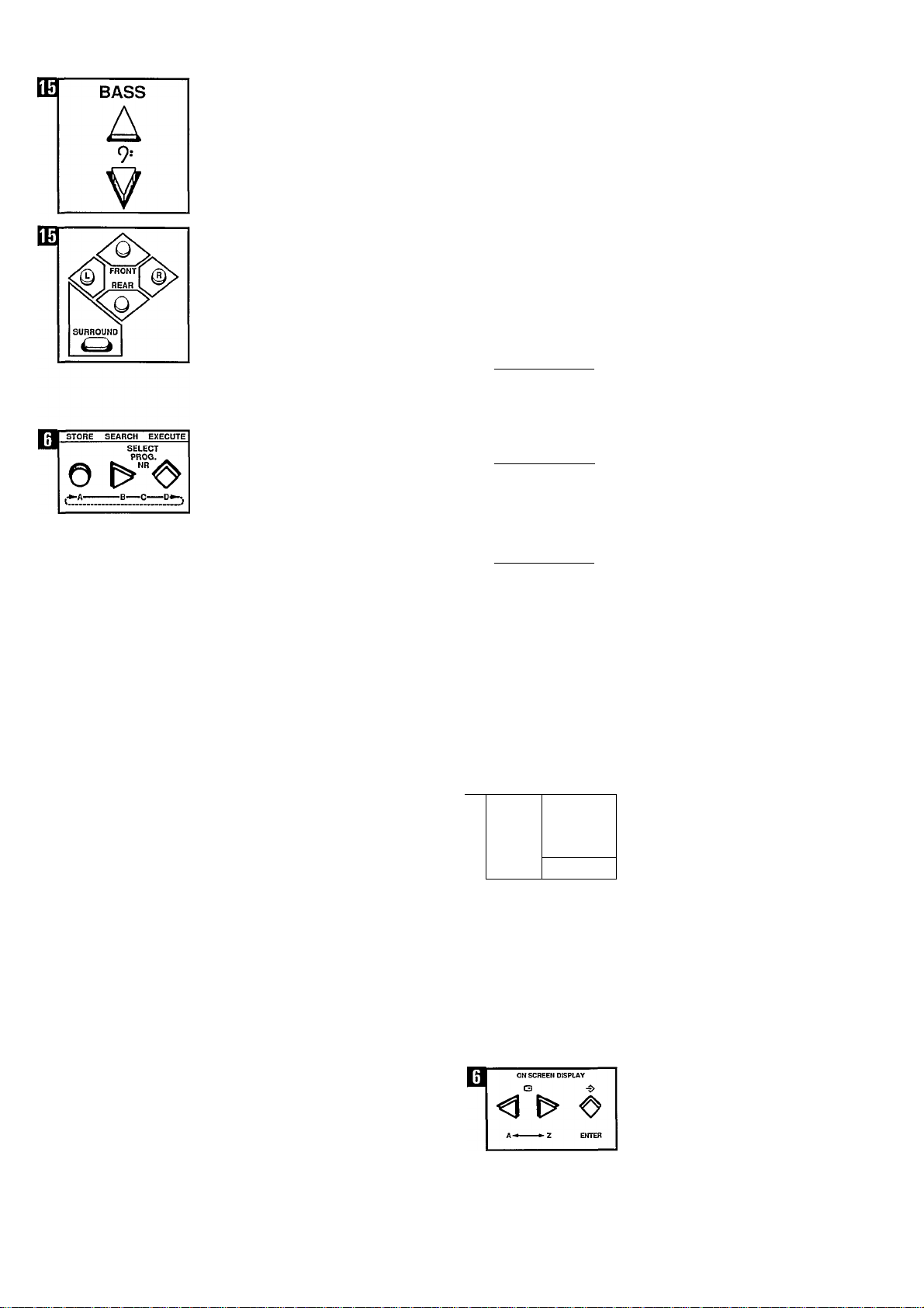
Low notes 9i (BASS),
Balance L/R,
The settings are indicated on the sound
control display on the A/V tuner
amplifier.
• Press the EXECUTE (D) button.
The changes are now stored in the
memory.
Note: The MONO/STEREO, SPATIAL
STEREO and LOUDNESS settings can
also be stored in the memory as
personal settings.
B. Television (monitor and
A/V tuner amplifier
combination)
Switching on monitor (if necessary)
• Press the POWER button.
Important!
in order to watch TV normally with the
monitor in combination with the A/V
tuner amplifier, the CONNECTIONS
switch, under the front flap of the
monitor, should be in the REAR
position and the VIDEO RGB/RGB
switch on the rear of the monitor in the
VIDEO RGB position.
• Press the TUNER VIDEO button.
TV followed by a programme number,
or TV.C with a channel number will be
displayed.
STORE SEARCH EXECUTe
О
STORE SEARCH EXECUTE
О
STORE SEARCH EXECUTE
О
MODE SYSTE»4
□
AUDIO F/P
T DOWN UP 1
e
SELECT
PROG. ^
SELECT
PROG. ^
SELECT
PROG,
tz)
VIDEO
Searching for and storing TV
stations in the memory of the
A/V tuner amplifier
Important!
Channel numbers
TV stations transmit prgrammes via TV
channels, indicated by TV.C followed by
a three-digit number (000 to 120).
Programme numbers
You select a TV station by giving your
own number (programme number) to a
TV station. These programme numbers
can be indicated by one-digit or
two-digit numbers (0 to 9 or 00 to 89).
Note: If necessary, place the A/V tuner
amplifier in the programme numbers
mode by pressing the VIDEO C/P
button (TV.C indication must not light
up).
A.
• Press the STORE (A) button.
TV indication starts to flash.
The indication PR followed by a
programme number will flash on the
screen of the monitor.
B.
• Press the SEARCH * (B) button.
TV indication starts to fiash.
The monitor screen changes and
ascending channel numbers appear on
the display of the A/V tuner amplifier.
If a TV station has been located, but the
picture is poor, or it is not the desired
station, continue to search by pressing
the SEARCH (B) button again.
• While you are searching for a station,
the word SEARCH also appears on the
monitor screen.
Green for PAL and NTSC, red for
SECAM.
If no TV station is located, you must
select another system by pressing the
SYSTEM button.
C.
• Once the desired TV station has
been located, select a programme
number.
Press the T DOWN or UP A button to
select the desired programme number.
Note: You can give 90 TV stations a
programme number (from 00 to 89).
If desired, a name can be
programmed with the TV station.
• Press button A or Z, depending on
the letter or figure to be selected. Once
the right letter has been found:
• Press the ENTER button.
Select the next letter or figure, etc.
Repeat these operations until the name
of the station has been stored.
In this way, a name can be given to a
maximum of 34 TV stations.
Page 10
m
STORE SEARCH EXECUTE
□
O
OSD
SELECT
PROG.
Note: The tuned-in TV stations and the
programmed station names can be
called up via OSD (to check them).
• Keep the OSD button depressed
until the list appears on the screen.
• Press the OSD button again to
switch OSD off.
• Press the EXECUTE (D) button.
Indication TV does not flash anymore.
The located TV station with the
programmed station name has now
been stored in the memory under the
programme number selected by you.
Searching for and storing
other TV stations
To search for and store the other TV
stations, repeat operations A, B, C
and D.
m
BRIGHT
A
■¿i-
Personal picture setting
The picture has already been stored in
the memory at a basic setting.
It is possible, however, to set the
picture according to your personal
preference and to store it in the
memory.
If desired, you can also switch on OSD
(for this, see the relevant section
‘Calling up OSD’).
To do this, press the plus A or minus
V side of the corresponding buttons
(plus at the top, minus at the bottom).
• Brightness (BRIGHT),
STORE SEARCH EXECUTE
SELECT
PROG.
O ^“<0’
ON SCREEN DISPLAY
Deleting programmed TV Station names (OSD)
• Select the required programme
number by means of the digital buttons
on the remote control unit.
• Press the STORE (A) button on the
A/V tuner amplifier.
• Press the <1 t> (A <-*■ Z) buttons
together.
The name of the TV station is now
replaced by 5 ‘stars’.
Press the EXECUTE (D) button.
m
B
COLOUR
HUE CONTRAST
A A
B
PERSONAL PREFERENCE
0 III m
SET AUDIO AND VJOEO CONTROLS
• Colour saturation 0 (COLOUR),
A
?
• Contrast (CONTRAST).
• Press the STORE EX O (C) button.
The changes are now stored In the
memory.
t
The programme number and station
name are now deleted from the OSD
list.
Page 11
m
m
m
^ToWER^
A-TU
CONNECT
Operation
A. Radio in combination with the remote controi unit
Switching on the A/V tuner amplifier (if
necessary)
• Press the POWER button.
Selecting the radio function on the
remote control unit
• Press the A-TU button.
The A-TU indication appears on the
display of the remote control unit.
• Press the CONNECT O* button.
Indication TU, followed by a programme
number or only the frequency, appears
on the display of the A/V tuner
amplifier.
SOUND SELECTION
o o
LOUDNESS ON.OFF
SOUND SELECTION
ld+ V
o o
LOUDNESS ON.'OFF
■ jV SOUND SELECTION
o o
LOUDNESS ON.'OFF
MONO
MONO
MONO
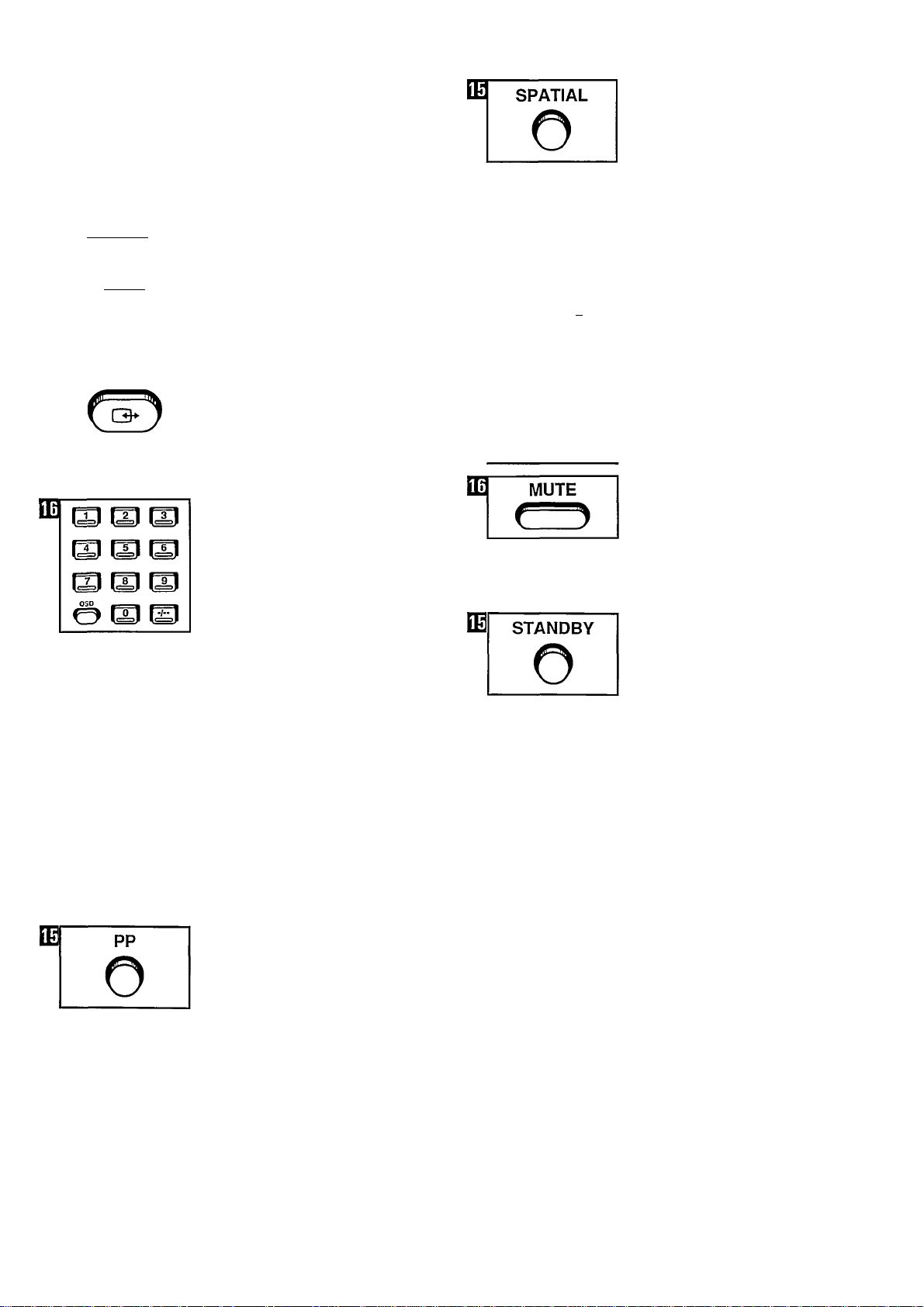
Spatial sound with stereo signals
• Press the SPATIAL button on the
remote control unit.
The G® indication on the A/V tuner
amplifier lights up.
• Press the SPATIAL button again to
switch off this effect.
Note: For this, the A/V tuner amplifier
must not be in MONO mode. (If
necessary, press the MONO ON/OFF
button.)
Mono
If the sound is reproduced in stereo,
you can switch back, if desired, to
MONO sound reproduction.
• Press the MONO ON/OFF button.
Loudness
The LOUDNESS button is used for
accentuating the high and low notes.
The indication id appears on the
display of the A/V tuner amplifier.
□ I
SOUND SELECTION
id*- V
o o
LOUDNESS OK’OFF
MONO
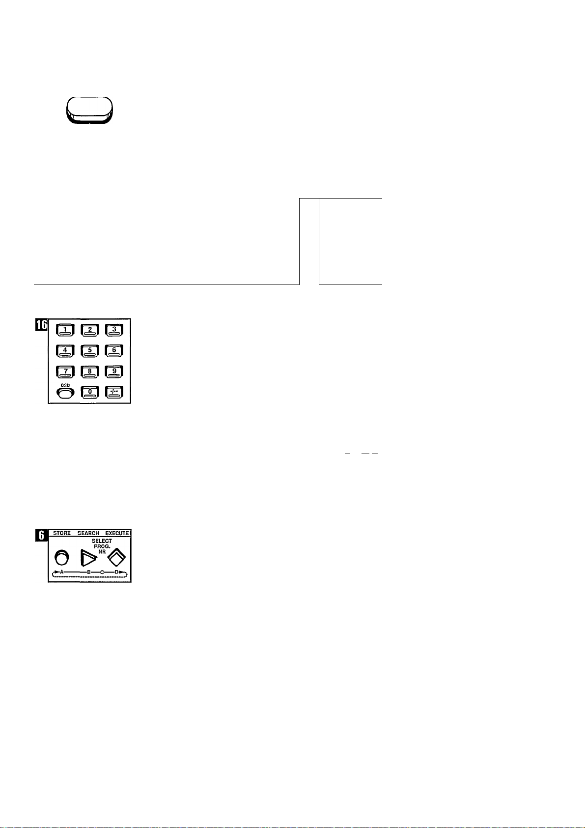
Programme seiection
Select the desired programme number
(radio station) with the digital buttons.
• First press the button for
programme numbers consisting of two
digits.
• Return to one-digit programme
numbers by pressing the button
again.
If the frequency is indicated, set the
A/V tuner amplifier in the programme
numbers mode by pressing the AUDIO
F/P button or by pressing F/P on the
remote control unit.
Changing the sound
If desired, you can change volume
high notes (g (TREBLE), low notes 9!
(BASS) and balance L/R with the
corresponding buttons on the remote
control unit.
See the indications on the display of
the A/V tuner amplifier.
Green button
After changing sound settings, you can
return to your personal preference.
• Press the green PP button.
Sound
stereo
During stereo transmissions for the
audio tuner, the indication 00 will
appear on the display, unless the A/V
tuner amplifier has been placed in
mono position with the MONO ON/OFF
button.
If the stereo signals are weak, sound
reproduction is automatically switched
to mono.
Muting
• Press the MUTE button.
• Press MUTE again to resume sound
reproduction.
Switching off with the remote control unit (STANDBY)
• Press the (!) STANDBY button on the
remote control unit.
The (1) indication on the A/V tuner
amplifier lights up.
If the remote control is in the A-TU,
TAPE, AUX.1 or AUX.2 mode, you can
switch the A/V tuner amplifier on again
by pressing the CONNECT O*- button.
Operating the A/V tuner
amplifier without remote
control
It is possibie to operate the most
important radio functions without using
the remote control unit.
AUDIO source selector with TUNER,
TAPE, AUX.1 and AUX.2 buttons.
UP/DOWN for selection of programme
number and VOLUME for sound.
It is also possible to select a radio
station directly.
• Press the AUDIO F/P button.
The frequency will be displayed.
• Select the required frequency (radio
station) using the UP or DOWN button.
Page 12
BT
^POVVER^
TV
DT CONNECT
C3-
B. Television (monitor) in
combination with remote
control
Switching on {if necessary)
• Press the POWER button on the A/V
tuner amplifier.
• Press the POWER button on the
monitor.
Seiecting the TV function on the
remote controi unit
• Press the TV button.
The TV indication appears on the
display of the remote control unit.
• Press the CONNECT Q*- button.
The TV indication followed by a
programme number, or TV.C followed
by a channel number, appears on the
display of the A/V tuner amplifier.
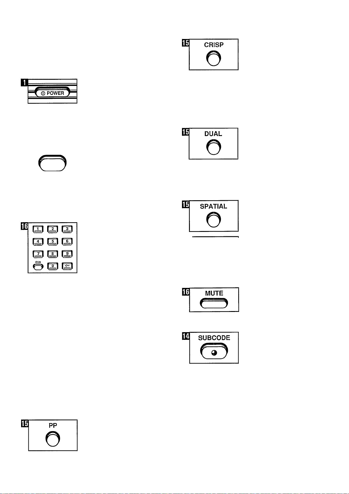
Picture/Contour accentuation
Depending on your preference, you can
switch on the picture/contour
accentuation.
Switching on (remote control should
be in TV mode)
• Press the CRISP button.
The CRISP indication on the monitor
lights up.
Switching off
• Press the CRISP button again.
The CRISP indication goes off.
Language seiection
For dual-language transmissions the
indication DUAL I or II will appear when
the corresponding programme number
is selected.
• Press the DUAL I button to hear the
other (2nd) language.
• Press the DUAL button again to
select the 1st language.
Programme selection
Note: if necessary, put the A/V tuner
amplifier in the programme numbers
mode by pressing the VIDEO C/P
button.
Select the desired programme number
(TV station) with the digital buttons.
• First press the •/- button for
programme numbers consisting of two
digits.
• Return to one-digit programme
numbers by pressing the •/■■ button
again.
Note: When a programme number is
selected, the number and, where
appropriate, the programmed station
name, appears for about 3 seconds in
the top right-hand corner.
During stereo transmissions the word
‘STEREO’ also appears.
During transmissions in two languages,
the word ‘DUAL’ I or II appears.
Changing picture and sound
If desired, you can change colour
saturation @ COLOUR), brightness
(BRIGHTNESS), volume high notes
I (TREBLE), low notes 9> (BASS) and
balance L/R with the corresponding
buttons on the remote control unit.
” V
SOUND SELECTION
O O
MONO
LOUDNESS OtLOFF
Spatial sound with stereo
signals
• Press the SPATIAL button.
The QO indication on the A/V tuner
lights up.
• Press the SPATIAL button again to
switch off this effect.
Note: For this, the A/V tuner amplifier
must not be in MONO mode. (If
necessary, press the MONO ON/OFF
button.)
Muting
• Press the MUTE button.
• Press the MUTE button again to
resume sound reproduction.
Time indication
• Press the 9 (SUBCODE) button.
If it is transmitted, the time appears in
the top right-hand corner of the screen.
• Press the 9 (SUBCODE) button
again to remove the time.
Green button
After changing the picture and sound
settings, you can return to your
personal preference.
• Press the green PP button.
Page 13

Picture In Picture (PIP)
PIP enables you, when you are
watching TV, to call up an extra
picture*, to swop it with the main
picture, to shift it and to freeze it.
Note: The remote control should be in
TV mode.
* a. The same picture as the main
picture.
b. The picture from a connected
CVBS source, for example a video
recorder. (This enables you, when
you are watching TV, to watch an
extra TV picture from another TV
programme or a video recording.)
For optimum use of PIP, it is advisable
that you have an extra tuner, for
example a video recorder, at your
disposal.
The following buttons are available on
the remote control unit:
PIP PIP on/off
SELECT Source selection
SWOP Swopping the picture
SHIFT Shifting the picture
FREEZE Freezing the picture
Source selection
Selecting the desired PIP source*
• Press the SELECT button.
Now another connected (PIP) source is
selected.
When a source is selected with the
SELECT button, the source name of
the main picture and the name of the
source selected for PIP will appear on
the screen (OSD).
* PIP sources
1. TV tuner of the A/V tuner amplifier as
PIP source (PIP picture has blue
frame).
2. PIP from videorecorder (PIP picture
has orange frame).
3. PIP from EXT.1 (PIP picture has
purple frame).
4. PIP from EXT.2 (PIP picture has
green frame).
Note: When the video recorder has
been selected, the stored TV stations
of the video recorder tuner can be
selected as PIP picture. You can either
do this via the programme selection
buttons on the remote control unit
(remote control in VCR mode) or direct
on the video recorder.
Connecting the (PIP) sources
(For connection of the sources, see the
chapter ‘Other equipment that can be
connected to the A/V tuner amplifier’.)
It is possible to obtain a PIP picture
from the internal TV tuner of the A/V
tuner amplifier and from 3 external
video sources with CVBS signals. In
that case, the video sources should be
connected to the Euroconnectors
(EXTERNAL 1, EXTERNAL 2, VCR) of
the A/V tuner amplifier.
Operating PIP
(with monitor and A/V tuner amplifier
switched on)
Switching on
• Press the PIP button.
The extra TV picture appears in the last
selected place and comes from the last
selected source.
Swopping the picture
• Press the SWOP button.
The main picture is swopped with the
PIP picture.
• Press the SWOP button again to
swop again.
Shifting the PIP picture
• Press the SHIFT button.
The PIP picture shifts every time the
SHIFT button is pressed.
Switching off
• Press the PIP button again.
Page 14

Freezing the PIP picture
• Press the FREEZE button.
The PIP picture is still.
• Press the FREEZE button again to
cancel the still PIP picture.
Note: The still picture will also be
cancelled when another PIP source is
selected or when the SWOP button is
pressed.
Using the video recorder with PIP
• Use the SELECT button to select the
video recorder as the PIP source.
a. Select the desired TV station in the
PIP picture using the programme
selection buttons on the remote control
unit (remote control in VCR mode) or
direct on the video recorder.
b. You can also watch a video tape in
the PIP picture by putting the video
recorder in play mode.
Still picture in TV mode
When watching TV, you can freeze any
TV picture as PIP picture (PIP is not
switched on here).
• Press the FREEZE button.
PIP is now switched on and the same
TV picture appears as a still PIP picture.
• The still PIP picture can be cancelled
by pressing the FREEZE button again.
Switching off with the remote control unit (STANDBY)
• Press the STANDBY button.
The (1) indication on the monitor lights
up.
You can switch the monitor on again by
pressing the CONNECT Q* button, if
the remote control is in the TV, VCR,
EXT.1 or EXT.2 mode. The A/V tuner
amplifier remains switched on.
If the remote control is in the A-TU
mode when the STANDBY button is
pressed, the indication (]) will light up
on the A/V tuner amplifier and on the
monitor.
You can switch the A/V tuner amplifier
and the monitor on again by selecting
the function TV, VCR, EXT.1 or EXT.2
and then pressing the CONNECT
button.
Operating the monitor and
the A/V tuner amplifier
without remote control unit
It is possible to operate the most
important monitor functions without
using the remote control unit.
VIDEO source selector with TUNER,
VCR, EXT.1 and EXT.2 buttons on the
A/V tuner amplifier.
UP/DOWN for programme number
selection (TV) and VOLUME for sound.
10
Page 15

Calling up OSD
On-Screen Display (OSD)
It is possible to call up various
functions on the screen.
• First select the desired OSD function
(1,2 or 3).
1. Press the OSD button.
The programme number in question
appears in the top right-hand corner of
the screen, where appropriate with TV
station name, STEREO or DUAL
indication.
2. When a picture setting is changed,
the picture function appears for a few
seconds as a bar on the screen.
3. Keep the OSD button pressed until
the picture functions appear as bars on
the screen. If you now change the
picture, the length of the bar will
change.
4. Keep the OSD button pressed until a
table appears showing the stored TV
stations (programme number, channel
number and programme station name).
5. Press the OSD button again after you
have OSD on the screen in order to
switch OSD off.
Note: The bars for volume and balance
will only be displayed when the built-in
loudspeakers of the monitor are
switched on.
Teletext
General Teletext description
If transmitted. Teletext provides you
with columns and pages of Information
about the most varied subjects.
The foilowing buttons are avaiiabie on
the remote controi unit:
TELETEXT Switching on teletext
TV Returning to TV programme
0 (MIX)
Mixing Teletext with TV
programme
X (CANCEL)
Cancelling Teletext
(ENLARGE)
Double height
(HOLD)
Stopping rotating pages
9 (SUBCODE)
Time code/subcode
? (REVEAL)
Revealing hidden information
0-9 Page selector buttons
<$♦ (NEXT)
Calling up page numbers from
memory
^ (ENTER)
Entering page number into
memory
The functions of the various Teletext
symbols are described later in these
instructions.
General information
(B) (©
oa
P101(g)125l'‘P101 (a)1259'‘P103 011310" E)l=l'
After Teletext has been switched on, an
information line will appear at the top of
the screen. Depending on your
selection, this can indicate the following:
0 = the number of the page which is
now on the screen (possibly combined
with time code, subcode or stop
rotating pages).
(¥] = the number of the page which is
going to come on the screen (possibly
combined with time code or subcode).
The colour is normally green, but once
the page is located, the colour
becomes white and this page number
goes to position (A) on the information
line.
0 = the page number that is being
stored.
The colour is normally green, but once
the page is located, the colour
becomes white.
0 = the Teletext symbol and,
depending on use, the symbol for
double size or hidden information.
11
Page 16

Operating Teletext in combination with the remote control unit
Switching on if necessary.
• Press the POWER button of the
monitor.
B
TV
• Press the POWER button of the A/V
tuner amplifier.
• Press the TV button.
The TV indication appears on the
display of the remote control unit.
A. Direct page selection
Page selection:
• Select the desired page with the digit
buttons on the remote control unit.
The selected page number is now
shown in green on the information line.
As soon as the selected page number
has been located, this page number is
shown in white.
(If the selected page number remains
green, this means that the selected
page number is not being transmitted
at that moment.)
Calling up the page:
• Press the •$* (NEXT) button.
o
If you do not select a new page
number, the next page number is
automatically sought.
• Press the <$• (NEXT) button again
when you want this page to be shown
on the screen.
w TELETEXT
• Press the TELETEXT button.
Page number 100 (usually the table of
contents) appears on the screen.
Page selection
The page number always consists of
three digits (e.g. 120).
Note 1: There are no page numbers
beginning with a 0 or a 9. if a 0 or 9 is
selected as the first digit, this selection
error is indicated by P-.. on the
information line.
Note 2: If you have pressed the wrong
digit button, you must first complete a
combination of three digits and then
select the right page number.
m
ENTER
B. Page selection of
temporarily stored page
numbers
An index page lists a number of
columns, each of which has a page
number. A selection of the page
numbers can be stored temporarily in
the memory.
The selected page numbers can only
be called up once in the stored
b. Press the -$> (ENTER) button.
Repeat these operations to store the
other page numbers.
Calling up pages:
• Press the (NEXT) button.
12
Note: If a selected page is shown in
red, no new page numbers can be
stored as the memory is full.
Page 17

C. Page selection of
permanently stored page
numbers
The permanent memory enables you to
store a maximum of 20 page numbers
which you regularly consult.
A list of these page numbers can be
called up and filled in irrespective of the
seiected programme number. In this list
you will see the stored programme and
page number on each line.
storing page numbers:
Note: The monitor should be in Teletext
mode.
• Open the flap by pressing the top
right-hand corner.
PERSONAL PREFERQlCe
Bf
STORE 1 STORE EX
SET AUDIO AND VIDEO CONTROLS
m
NEXT
m
o
Ed
ENTER
o
lOo
it] ii
2H f3
T1
a. Press the STORE ^ (A) button on
the TV.
The list will now appear on the screen.
If page numbers have already been
stored, they can, if desired, be deleted
by pressing the <$» (NEXT) button on
the remote controi unit continually until
all 20 lines of this list are blank (this can
be recognised by ..P.. on the screen).
b. Select the desired programme
number (TV station with Teletext
transmissions). Always two digits, e.g.
01
.
c. Select the desired page number.
d. Press the (ENTER) button.
Repeat operations b, c and d to store
the other page numbers.
e. Press the STORE EX O (C) button
on the TV.
The entered programme and page
numbers are now stored in the
memory. This is indicated by means of
a change of colour.
Calling up pages:
a. Press the TV button.
13
Page 18

Note: The page number indicated by
the coioured bar and the foiiowing
pages will shift downwards one
position. The page number to be
added goes to the line which is
indicated by the coloured bar.
c. Select the desired prgramme
number (always two digits, e.g. 01).
d. Select the desired page number.
e. Press the (ENTER) button.
Time code/subcode
The Teletext producers may decide to
add a time code or subcode to page
numbers.
This makes it possible:
a. to call up a page at a desired time
(time code), or
b. to select directly one of the rotating
Bl
PERSC^ PREFEI^CE
STORE
0© lo^
E]
ca AUDSO Aj;0 VIDEO CONTROLS
I£j HOLD
©
1 STORE EX
di ID
If necessary, repeat operations b, c, d
and e to add more page numbers.
f. Press the STORE EX O (C) button on
the TV.
Other Teletext functions
Double height
• Press the (ENLARGE) button for
double height of the top half of the
page.
• Press the -i- (ENLARGE) button
again for double height of the bottom
half of the page.
• Press the -4- (ENLARGE) button
again for normal height.
When a page is shown in double
height, the (ENLARGE) symbol
appears on the information line.
Cancelling Teletext
• Press the X (CANCEL) button.
The monitor stays in Teletext mode,
showing the tuned station on the
screen. As soon as the desired page
has been located, the page number
appears in the top left-hand corner of
the screen.
• Return to Teletext by pressing the X
(CANCEL) button again.
Stop rotating pages
If a page contains more text than a
Teletext page permits, rotating pages
are often used within the same page
number.
• Press the ^ (HOLD) button.
The 1^1 (HOLD) symbol appears on the
information lines and the page stops
(stop).
• Cancel stop by pressing the
(HOLD) button again.
id SUBCODE
• Press the 9 (SUBCODE) button.
• Select the desired time (e.g. 13:19
hours).
On the information line there now
appears e.g. P12391319.
b.Subcode
• Select the desired page number (e.g.
123).
• Press the 9 (SUBCODE) button.
• Select the desired subcode (e.g. 3).
On the information line there now
appears PI2393.
Note: The selected page, followed by
time code or subcode, can be:
a. called up directly by pressing the <$*
(NEXT) button, or
b. stored in the temporary memory by
pressing the ■$’ (ENTER) button.
Hidden information
Depending on the page content, hidden
information can be called up.
• Press the ? (REVEAL) button.
The ? (REVEAL) symbol appears on
the information line and the hidden
information appears on the screen.
• Press the ? (REVEAL) button again.
The information disappears.
14
Page 19

Teletext with TV programme
• Press the CD (MIX) button.
• Return to Teletext by pressing the (D
(MIX) button again.
Other equipment that can be connected to the A/V tuner amplifier
L
1 mp»—
iS^ -i-l
___
1. Video recorder
You can connect a video recorder to
Euroconnector VCR.
• Press the VCR button.
15
Page 20

• Press the CONNECT Q* button.
El
3. CD Video Player (CDV)
You can connect a CDV to
Euroconnector EXTERNAL 2.
To operate the video recorder:
See the operating instructions of the
video recorder.
Note: When you connect a HiFi video
recorder and you aiso want to use it as
an audio recorder, connect the Cinch
Audio outputs and inputs of the video
recorder with the Cinch terminais
(TAPE iN/OUT) of the A/V tuner
ampiifier.
Important!
• When you connect a video recorder
with OSD (e.g. Matchline video
recorder VR6970) to the A/V tuner
amplifier in combination with a
Matchline monitor, a picture breakdown
may occur if you cange over from the
A/V tuner amplifier to the video
recorder, when the OSD of the monitor
and the OSD of the video recorder
appear on the screen at the same time.
• If you put the video recorder in the
still picture mode and you switch on the
OSD of the monitor, a picture
breakdown may occur.
• If you have connected the Matchline
video recorder VR6970 to the A/V tuner
amplifier, you can switch this video
recorder to EXTERNAL with the
CONNECT button on the remote
control unit. The same thing happens
when this video recorder is in record
mode. When the video recorder is
recording from the internal video
recorder tuner and you press the
CONNECT button, the video recorder
will switch over and record from an
external source.
m
m
EXTERNAL 2 Q*
EXT 2
C>
TAPE
O
CONNECT
• Press the EXT 2 button.
See the operating instructions of the
CDV.
4. Audio Cassette Recorder
You can connect an Audio Cassette
Recorder to the Cinch terminals (TAPE
IN/OUT).
• Press the TAPE button.
• Press the CONNECTQ» button.
IT
m
m
EXTERNAL 1 C3*
EXT1
O
CONNECT
2. Satellite Tuner
You can connect a Satellite Tuner to
Euroconnector EXTERNAL 1.
Press the EXT 1 button.
• Press the CONNECT button.
To operate the Satellite Tuner:
See the operating instructions of the
Satellite Tuner.
Note: When you connect a source with
RGB signals (e.g. Satellite Tuner) to
EXTERNAL 1, the O* indication will
light up on the monitor.
For operating the Audio Cassette
Recorder:
See the operating instructions of the
Audio Cassette Recorder.
Note: You can also connect a HiFi
video recorder to these Cinch terminals
(TAPE IN/OUT).
5. Record player
You can connect a record player with
MD system to Cinch terminal AUX 1.
Note: if desired, you can earth the
record player via the PHONO GROUND
screw terminal.
• Press the AUX 1 button.
16
Page 21

Press the CONNECT Q* button.
To operate the record player:
See the operating instructions of the
record player.
6. Compact Disc Player (CD)
• Enter the desired two-digit code with
the digit buttons on the remote control
unit.
Code Indication Source
00 TV Teievision
02 TXT Teletext
04 LV LaserVision
05 VCR Video recorder
08 SAT Satellite Tuner
12 CDV CD Video Piayer
• Press the EXECUTE (D) button.
Note: The remote control unit should
also be programmed for the ‘new’
source name. For this, see
‘Reprogramming source selector
buttons EXT.1 and EXT.2’ in the section
on ‘Programming the remote control’.
To operate the CD player:
See the operating instructions of the
CD player.
It is possible to connect a suitable
piece of equipment to the A/V tuner
amplifier via the REMOTE OUT
terminal.
A unit connected in this way can also
be operated with the remote control
unit.
Important!
A unit that is suitable for remote control
and that has been connected with
Eurocables, receives the signals from
the remote control unit via the monitor
and the A/V tuner amplifier through the
Euroconnectors.
Note: Euroconnectors EXT 1 and EXT
2 can be programmed for other
connections (sources).
For this, see the relevant text.
(Re) programming the source
name for EXT 1 and EXT 2
• Press the desired button EXT 1 or
EXT 2.
O ^ b
Headphones
This terminal on the A/V tuner amplifier
is for a set of headphones with an
impedance between 8 and 1000 ohms
and is of the 6.3 mm jack type.
With headphones connected, you can
adjust the volume with the
—VOLUME-F buttons.
Use the DUAL I-II buttons on the A/V
tuner amplifier for selecting another
language (if transmitted).
Note: Language selection is only
possible in position TV.
If a video tape or a CDV disk is
muitilingual, you can select the
language with the DUAL button on the
remote control unit.
• Press the STORE (A) button.
The CODE? indication flashes on the
display of the A/V tuner amplifier.
17
Page 22

The multifunctional system remote control
2. Digit buttons 0 to 9
For selecting a one-digit number, press directly 0 to 9.
For selecting a two-digit number, first press the button and
then the number (e.g. 10 to -).
To select a teletext page, first press a three-digit number.
This multifunctional remote control can be used for the A/V tuner
amplifier and monitor (and any other connected equipment from
our series), which work on the present standardised (RC5)
operating signals.
The receiver of the remote control signals is buiit into the
monitor. The A/V tuner amplifier, in combination with the monitor,
receives the signals from the remote control unit via the
Eurocable. The monitor should be in standby mode or shouid be
switched on to receive the signals from the remote control unit.
Remote control unit
Inserting batteries
• Open the flap and remove it.
Brief description of the buttons and functions
1. Source selector buttons*
VIDEO
Button Indica
TV
VCR
EXT1
EXT 2
AUDiO
Button Indica
A-TU
TAPE
AUX 1
AUX 2
* After the source is selected, the CONNECT button should be
pressed to reproduce the source.
If you only select the source on the remote control unit and you
do not press the CONNECT button, you can only operate the
functions of the selected source (e.g. video recorder) via the
remote control unit.
tion
TV
VCR
SAT
CDV
tion
A-TU
TAPE
PHON
CD
Function
switching over to TV
switching over to video recorder
switching over to Satellite Tuner
switching over to CD Video Player
Function
switching over to Radio
switching over to Audio Cassette Recorder
switching over to Record Player
switching over to Compact Disc Player
3. Picture and sound —/-f and baiance L/R buttons
Button Function
COLOUR colour saturation
BRIGHT picture brightness
TREBLE high notes
BASS low notes
L/R balance (division of sound)
FRONT/REAR balance when the Dolby Surround Processor Is
VOLUME sound level
4. Teletext buttons
Button Function
TELETEXT switching on Teletext
ENLARGE double height
HOLD stopping rotating pages
REVEAL calling up hidden information
CANCEL ‘temporarily’ cancelling Teletext
NEXT calling up page numbers from the memory
ENTER entering page numbers in the memory
MIX Teletext together with TV programme
SUBCODE calling up page numbers at set time and directly
5. Tape transport buttons for audio and video equipment
(The functions in bold (picture) are only for video equipment)
Button Function
PAUSE temporarily interrupting picture and sound
REWIND winding the tape backward
PLAY starting picture and sound playback
WIND winding the tape forward
RECORD recording picture and sound
REVERSE fast picture in reverse
STOP stopping picture and sound
FORWARD fast picture forward.
6. Other function buttons
Button
STANDBY
OSD
CRISP
DUAL
SPATIAL
PP
MUTE
Only if the remote control is in position TV:
PIP on/off
SELECT source selection PIP picture
SWOP swopping main picture and PIP picture
SHIFT shifting PIP picture
FREEZE freezing PIP picture.
7. Function buttons A, B, C and D
With these buttons you can select preprogrammed operating
functions (see code table).
used
selecting a rotating page number
recording/playback
Function
switching off picture when the remote control is
in position TV.
Switching off picture and sound when the
remote control is in position A-TU.
making various function indications visible via
the monitor
switching on picture/contour accentuation
selecting 1st or 2nd language (original or
dubbed language)
sound with extra spatial effect
(green button) returning to preferred personal
setting of picture or sound/autotracking VCR
muting sound.
18
Page 23

8. Display
IB
I A I B I C I D I
m
WmkiEi
DISPLAY
The display indicates the selected
source and the programmed operating
functions A, B, C and D.
Switch on the display with the DISPLAY
button, or by giving instructions with
the other buttons.
The display is automatically switched
o
off if no more instructions are given for
about 30 seconds.
9. STORE OPEN and STORE EXECUTE buttons
With these buttons other sources and functions can be ■
programmed.
2. Reprogramming buttons A, B, C
and D
(See the function code table for the
programming of the system remote
control unit.)
If desired, you can program buttons A,
B, C or D for another function.
• Select the source under which you
want to change function A, B, C or D
(TV, VCR. EXT 1, EXT 2. TXT. A-TU,
TAPE. AUX1 orAUX2).
• Press the ^ (OPEN) button.
The indications A, B, C and D will flash
on the display.
Programming the remote
control
1. Reprogramming source selector
buttons EXT 1 and EXT 2
If desired, you can program buttons
EXT 1 and EXT 2 for another source*.
• Select the source to be changed
(EXT 1 or EXT 2).
• the C> (OPEN) button.
The indications on the display will flash.
• Now select with the digit buttons the
two-digit code for the source to be
selected.
The display will now indicate alternately
the newly selected code and its
abbreviation. Furthermore the
programmed functions A, B, C and D
are shown.
Code Indication Source
00 TV Television
02 TXT Teletext
04 LV LaserVision
05 VCR Video recorder
08 SAT Satellite Tuner
12 CDV CD Video Player
• Press the O (EXECUTE) button.
The flashing stops and the newly
selected source is stored in the
memory.
Important!
If you have programmed a new source
name on EXT 1 or EXT 2 of the remote
control unit, you should also program
the new source name on EXT 1 or EXT
2 of the A/V tuner amplifier.
IT
r*7P
TUNER-I I 1
AUX.1^-1 1-AUXJ2
RECORDING
TO TAPE
TUNER-I I I
AUX.1—1 L.AUX2
RECORDING
TO VCR
GD
TUNER-i I I ^ AUDIO
EXT.1
------
1 »
-----
EXT.2
• Select the button A, B, C or D to be
programmed.
Flashing bars will appear as an
indication in the appropriate place.
• Now select with the digit buttons the
three-digit code for the function to be
selected (see the code table in the
back).
The display now indicates alternately
the newly selected code and its
abbreviation.
• Press the O (EXECUTE) button.
The flashing stops. The newly selected
function is stored in the memory.
Sound and picture recording
facilities
It is possible to make picture and
sound recordings from equipment
(sources) connected via the A/V tuner
amplifier and to watch or listen to
another source at the same time.
1. For recording with an Audio Cassette
Recorder or a HiFi video recorder that
is used as an audio recorder, the TO
TAPE switch shouid be in position
TUNER (Radio), AUX1 (Record player)
or AUX2 (Compact Disc), depending
on which source is to be recorded.
2. For recording with a video recorder,
the TO VCR switch should be in
position TUNER (TU), EXT 1 (Satellite
Tuner) EXT 2 (CD Video Player) or
Audio, depending on the source to be
recorded.
The audio source to be recorded is
determined by the position of the TO
TAPE switch.
Note: For recording you should also
consult the operating instructions of
the equipment to be used.
19
Page 24

EI
VIDEO
RGB
Using the monitor as a screen without the A/V tuner amplifier
The monitor can also be used directly
for playing back equipment (sources)
such as a video recorder, CD Video
Player and Satellite Tuner.
These sources can be connected to
the Euroconnector and/or Cinch
terminals.
If you connect a source with RGB
signals (e.g. Satellite Tuner) to the
monitor, the RGB indication will light up
on the monitor.
Note: If a connected source transmits
TV antenna signals, you can also watch
Teletext.
• Open the flap by pressing the lug in
the bottom right-hand corner.
1. Euroconnector on the back of the
monitor
If a unit connected to the
Euroconnector supplies RGB signals
without switch-over signals, the VIDEO
RGB/RGB switch should be in position
RGB.
• Put the CONNECTIONS switch in the
REAR position.
Monitor function via PIP
A source connected to the PIP input of
the monitor (e.g. Camera) can be
entered in the PIP picture with the PIP
on/off button on the remote control
unit.
BF
PERSONAL PREFERENCE • PFGSS tllG STORE EX ^ (C) bUttOP.
STORE I STORE EX
oÖIÖo
E [II S
SET AUDIO AND VIDEO CONTROLS
EJ
El
MONITOR SOUND
LEFT RIGHT
BALANCE
MONITOR SOUND
LEFT RIGHT0V
BALANCE
• Open the control panel by pressing
the top right-hand corner.
• Make the desired change.
The changes are now stored in the
memory.
Sound
MONO
If the sound is reproduced in stereo,
0
you can, if desired, switch back to
V
MONO.
• Press the MONO button.
MONO
The MONO indication lights up.
Balance
You can adjust balance with the LEFT
and RIGHT buttons.
MONO
Volume
You can adjust the volume of the
monitor with the A and V VOLUME
buttons.
If external loudspeakers are
connected, you can switch off the
internal loudspeakers with the
VOLUME ON/OFF button,
STEREO
During stereo transmissions, the
STEREO indication appears on the TV
screen.
20
2. Cinch terminals on the front of the
monitor
The VIDEO terminal is a CVBS input.
The AUDIO L and R inputs are for the
sound of a unit connected to the VIDEO
input.
• Put the CONNECTIONS switch in
FRONT position.
Operating facilities
Personal setting and changing of
picture and sound
Note: The monitor must not be in
Teletext mode.
Page 25

General
Technical information
What to do when there are faults
• if the combined unit does not
operate as desired, check that there is
mains voitage, that the antenna is
connected and that aii switches are in
the right positions.
• If there is no sound, check if the
MUTE button is depressed.
• if no Doiby Surround Processor has
been connected, the ‘surround sound’
switch on the A/V tuner ampiifier
should be in position OFF.
• Is the VIDEO RGB/RGB switch in the
right position?
• Is the CONNECTIONS
(FRONT/REAR) switch in the right
position?
• If there is a sharp white stripe on the
TV screen, if the letter ‘F’ with a digit
appears on the display of the A/V tuner
amplifier or if the indication flashes
although you are not operating the
combined unit, you should switch off
the TV and consult your dealer.
Cleaning the combined unit
If necessary, you can clean the unit
with a damp chamois-leather cloth. Do
not use abrasive cleaning agents.
MODE
VIDEO CP
O
T DOWN UP i
c
MODE SYSTE».!
u
o
AUDIO F/P VIDEO
U
T DOWN UP i
e
o
Radio frequency selection
• Press the AUDIO F/P button.
A radio frequency appears on the
display.
• Press the T DOWN or UP ▲ button
to select the desired frequency of the
y
radio station.
TV channel selection
• Press the VIDEO C/P button.
The TV.C indication and a channel
number will appear on the display.
• Press the T DOWN or UP A button
to select the desired TV station.
Note: You will find a list of channel
numbers and their indication under the
section ‘Channel number indicatons on
the screen’.
Specifications of the Euroconnectors, Monitor and A/V tuner amplifier
A = Monitor input lOI (on the monitor)
B = Monitor input OI
C = External 1C3*
D = External 2 Q*
E = VCR <a
Pin
1 audio output (right channel)
2 audio input (right channel)
3 audio output (left channel)
4 earth terminal audio
5 earth terminal B input
6 audio input (left channel)
7 B input
8 remote control signals
+ status input (EXT 1)
9 earth terminal G input
10 not connected
11 G input
12 not connected
13 earth terminal R input
14 not connected
15 R input
16 fast blanking input
17 earth terminal CVBS
18 earth terminal fast blanking
19 CVBS output
20 CVBS input
21 screening
0.5Vrms/1kohm
0.5Vrms/10kohm
0.5Vrms/1kohm
0.5Vrms/10kohm
0.7Vpp/75ohm
0-2/10-12V/10kohm x x x
0.7Vpp/75ohm
0.7Vpp/75ohm x
0-0.4V/1-3V/75ohm x
1 Vpp/75 ohm
1 Vpp/75 ohm
A B C D
XXX
XXX
X
X
21
Page 26

Channel number indications on the screen
Channel indication
A
B
C
D
E
F
G
H
L
51
52
53
51
52
53
02 to 04
05 to 12
21 to 69
Italian channels
S channels band I
S channels band m
Channel number
VHF (band I)
VHF (band m)
UHF(band m)
13
14
15
16
17
18
19
20
11
74
75
76
80
81
82
Hyperband
Audio FM*
Audio AM**
FM in steps of 50 kHz
AM in steps of 9 kHz.
98
99
100
101
119
120
519
520
87.5 MHz
108.0 MHz
522 kHz
1611 kHz
22
Page 27

Page 28

Code table for the programming of the system
remote control and A/V tuner amplifier
(Codes apply to Philips audio and video equipment)
Source codes for system remote Function codes for system remote control
control and A/V tuner amplifier (A,B.C,D)
Source Abbrev. Code for Function Abbrev.
on LCD
Television TV 00**
Teletext TXT
Laser LV 04
Vision Chapter number CNR
Player
* These functions are preprogrammed on the remote control
EXT 1, EXT 2
Channel/Program
mode
Search + SE +
Step C/P ST + 032*
Step C/P STStereo/Mono STE
02** Step page + PS + 010*
Step page Picture number/time
Repeat
Repeat loop
Next
Fast reverse FMR031
Entry ENT 032
Auto stop AST 033
Siow reverse
Audio IA-1
Audio li A-2
Still reverse STR
Speed +
Speed - SP-
Slow forward SMF
Fast forward FMF 042
Goto GTO 043
Eject ECT 045
Play reverse
Pause PSE
Correct COR 049
Clear memory CLM
Freeze FZE
TXT submode TXT 060
CX on/off CX
on LCD A.B,C,D
C/P
PS- 011*
P/T
REP
NXT
SP + 038
PLR
unit.
These sources are fixed-programmed on the remote control
unit and the A/V tuner amplifier.
These sources are preprogrammed on the remote control
unit and the A/V tuner amplifier.
Code for
Oil
030*
033*
037
010
Oil
028
RLP029
030
SMR034
035
036
037
039
040
047
048
058
059
062
Source codes for system remote Function codes for system remote control
control and A/V tuner amplifier (A.B,C.D)
Source Abbrev.
on LCD EXT1,EXT2 on LCD
Video VCR
Recorder iTR
Sateilite SAT
Tuner
Code for
05**
08*** Audio mix mode ind.AMM
Function Abbrev.
Timer mode TPR
Slow motion SMF 040*
Fast motion
C/P C/P
Call DIR
Recording mode sel.030 030
Program + ST + 032
Program - STSlow motion reverseSMR 034
Dispiayscroli
Speed - SPSpeed + SP-F
End END
Eject ECT
Play reverse PLR
Correct COR
Goto
Short/Long play SLP
Memory MEM
Channel +
annel- ST- 033*
ITR 039*
FMF
DPL
GTO 051
ST + 032*
Code for
A, B, C, D
029*
042*
Oil
028
033
036
037
038
043
045
047
049
058
059
037*
* These functions are preprogrammed on the remote control
unit.
** These sources are fixed-programmed on the remote controi
unit and the A/V tuner amplifier.
*** These sources are preprogrammed on the remote control
unit and the A/V tuner ampiifier.
Source codes for system remote Function codes for system remote control
control and A/V tuner amplifier
Source Abbrev. Code for
on LCD EXT1,EXT2 on LCD
CD Video CDV
Player
Audio A-TU
Tuner
12*** Repeat loop RLP
17** Freq./Program F/P
(A,B,C.D)
Function Abbrev.
Preveous PRV
Next NXT
Pause PSE
Picture number/timeP/T
Chapter/track sel. C/T
Repeat REP
Programming PRG 031
Auto stop AST 033
Slow reverse SMR
Still reverse STR
Speed + SP +
Speed Slow forward SMF 040
Still forward 041
Seq. of frames
Eject
Goto GTO
Clear memory CLM
A/B program
Search + SF +
Program + PR + 032*
Program - PR- 033*
Stereo/Mono
SP- 039
SEF
ECT
A/B
STE
code for
A, B, C, D
029*
036*
030*
048*
010
oil
028
034
037
038
041
042
045
051
058
059
011*
030*
037
These functions are preprogrammed on the remote control
unit.
These sources are fixed-programmed on the remote controi
unit and the A/V tuner amplifier.
These sources are preprogrammed on the remote control
unit and the A/V tuner ampiifier.
133
Page 29

Source codes for system remote Function codes for system remote control
control and A/V tuner amplifier
Source Abbrev. Code for
on LCD EXT 1, EXT 2
Audio TAPE 18**
Cassette
Deck
Turntable PHON 21**
CD Player CD. '20**
* These functions are preprogrammed on the remote
(A,B,C,D)
Function
Repeat
Repeat loop
Next
Previous
Repeat A and B
Blank search
Record blank
Mechanism A
Eject
Mechanism B
Play reverse
Erase/Reset
Repeat A/B program A/B
Counter memory MEM
store
Repeat once
Repeat continuously
Select +
SelectNext
Previous
Repeat loop
Store execute
Next
Previous
Repeat
Select +
Select -
Next index
Previous index PRI 035
Play/Program
Scan
Clear memory
A/B program
Dyn suppr. +
Dyn suppr. -
Abbrev. Code for
on LCD
REP 028*
RLP 029*
NXT 032*
PRV 033*
A + В 036
NBL 037
RNL 042
A 044
ECT 045
В 046
PLR 047
RES 049
REP 028
RLP 029
ST + 030
ST-
NXT 032
PRV 033
RLP 029*
STO 041*
NXT 032*
PRV 033*
REP 028
ST + 030
ST- 031
NXI 034
P/P 036
SCN 043
CLM 058
A/B 059
DY + 060
DY- 062
A.B,C,D
059
062
031
i control
unit.
These sources are fixed-programmed on the remote control
unit and the A/V tuner amplifier.
These sources are preprogrammed on the remote control
unit and the A/V tuner applifier.
134
Page 30

Page 31

Page 32

ERRATA
English
DI МОМГГОЯ
Deutsch
IQIМОМПСЖ
Français
IQI MWttOR
English
Deutsch
Français
......-„TV
Page 2
MONITOR O (A/V tuner amplifier).
t
t
Seite 24
MONITORo(am Audio/Video-TunerAmplifier).
Page 45
MONITORadu tuner-amplificateur
audio-vidóo.
Page 5 and 8
Indication TV.C-TV
Selte 26 und 29
Anzeige TV.C-TV
Page 48 et 51
La mention TV.C-TV
Nederlands
В
Dl «owro«
Italiano
IO «ofetOÄ
Español
Nederlands
Italiano
Español
Pagina 67
MONITOR о (A/V tuner amplifier).
Pagina 88
MONITOR o (sintonizzatore /
amplificatore AA/) del sintonizzatore /
amplificatore AA/.
Pagina 110
MONITOR a (amplificador-sintonizador
de AA/).
Pagina 70 en 73
Indikatie TV.C-TV
Pagina 91 e 94
Indicazione TV.C-TV
Página 113 y 116
Indicación TV.C-TV
English
к A I B I c f 0 I
ММИЯМЙМЁЙЁМЁ
Deutsch
mm
Français
sms
I A I B к C i t> I
Paga,Selte, Pagina, Página 134
Laser
Vision
Player
LV 04
Page 19
• Select the button A, B, C or D to be
programmed.
Flashing bars will appear as an indication
in the appropriate place.
Seite 41
• Die zu programmierende Taste A,B|C,
Oder D Wahlen.
t
Die Wahl wird mit blinkenden Strichen
angezeigt.
Page 63
• Choisissez ia touche dont vout voulez
modifier la programmation (A,B|C,ou D,).
Un curseur clignotant apparaît sous la
lettre correspondant à la touche choisie.
Repeat loop
Next
Fast reverse
Entry ENT 032
Auto stop AST
Slow reverse
Audio A-1
029
RLP
030
NXT
FMR 031
033
034
SMR
035
Nederlands
ПГТТ
italiano
Ш
ГТТТТТТТ1
ЙЙЙЙЙЙЙЙЙЙЙЙ
Español
ПГТТТТТТ1
ЙЙЙЙЙЙЙЙЙЙЙЙ
clôt
ШЙЙЙ
mm
mss'
Pagina 84
• Kies de te programmeren toets A.B.C
ofD.
Ter indikatie verschijnen op de betreffen
de plaats knipperende streepjes.
Pagina 106
• Seleztonare il tasto A.B.C о D.
L'indicazione sul display viene sostituita
da lineette lampeggiante.
Página 128
• Elija la tecla de programación A, B, C
oD.
Ahora parpadean las rayas en el corres
pondiente lugar.
3104305 2550.1
Page 33

Page 34

Die Deutsche Bundespost informiert
Sehr geehrter Rundfunkteilnehmer!
Dieses Gerät ist von der Deutschen Bundespost als Ton- bzw. Fernseh-Rundfunkempfänger bzw. als Komponente
einer solchen Anlage (Tuner. Verstärker, aktive Lautsprecherbox, Fernseh-Monitor u. dgl.) zugelassen. Es entspricht
den zur Zeit geltenden Technischen Vorschriften der Deutschen Bundespost und ist zum Nachweis dafür mit dem
Zulassungszeichen gekennzeichnet. Bitte überzeugen Sie sich selbst.
Dieses Gerät darf im Rahmen der umseitig abgedruckten ’Allgemeine Genehmigung für Ton und Fernseh-Rundfunk
empfänger’ in der Bundesrepublik Deutschland betrieben werden. Beachten Sie aber bitte, daß aufgrund dieser
Allgemeinen Genehmigung mit Rundfunkempfängern nur Sendungen des Rundfunks empfangen werden dürfen *
Wer unbefugt andere Sendungen (z.B. des Polizeifunks, des Seefunks, der öffentlichen beweglichen Landfunkdien
ste) empfängt, verstößt gegen die Genehmigungsauflagen und macht sich daher nach § 15 Absatz 2a des Gesetzes
über Fernmeldeanlagen strafbar.
Die Kennzeichnung mit dem Zulassungszeichen bietet Ihnen die Gewähr, daß dieses Gerät keine anderen
Fernmeldeanlagen einschließlich Funkanlagen stört.
Der Zusatzbuchstabe S * *) beim Zulassungszeichen besagt außerdem, daß das Gerät gegen störende Beeinflussun
gen durch andere Funkanlagen (z.B. des Amateurfunks, des CB-Funks) weitgehend unempfindlich ist.
Geräte ohne den Zusatz S sind nicht besonders störfest.
Sollten bei Geräten mit dem Zusatz S ausnahmsweise trotzdem Störungen auftreten, oder wenn Sie Fragen haben,
so wenden Sie sich bitte an die örtlich zuständige Funkstörungsmeßstelle.
*) Zum Empfang anderer Sendungen darf dieses Gerät nur mit Genehmigung der Deutschen Bundespost benutzt werden. Allgemein
genehmigt Ist zur Zeit der Empfang der Aussendungen von Amateurfunkstellen und der Normalfrequenz- und Zeitzeichensen
dungen.
**) Weitere Zusatzbuchstaben haben in Bezug auf die Störfestigkeit keine Bedeutung.
**)
).
3122125 91741
986/4
Page 35

Alla
für Ton- und
Die allgemeine Tor
11 Dezember 1970
vom 16. Dezember
Genehmigung durcl'
migung für Ton- ui
§§ 1 und 2 des Gei
Genehmigung für 'on- und Fernseh-Rundfunkempfanger
1. Die Errichtung ui
funkempfängern
Fernmeldeanlage
17.3.77 (BGBL
2 Ton- und Fernsi
nehmigungsind
über Fernmeldei
empfänger zugel
weisen und zun*
Sichtbarmachen
bestimmt sind. Zi
mit ihm fest verl
mehrere Geräte
Außer für den Егт)]
und Fernseh-Rui
migung der Deui
zwecke zusatzli
In den Empfänge eingebaute oder sonst mit ihm verbundene
Zusatzgeräte (z.B. Ultraschallfernmeldeanlagen. Infrarotfern-
meldeanlagcn) w irden von dieser Genehmigung nicht erfaßt
(ausgenommen d e Einrichtungen zum Empfang des Verkehrs
rundfunks). Desg eichen sind andere technische Empfänger
eigenschaften, dl i über den eigentlichen Zweck eines Rund
funkempfängers hinausgehen (z.B. zum Empfang anderer
Funkdienste, für ±e Wiedergabe im Rahmen von Textübertragungsverfahre i). hierdurch nicht genehmigt Hierfür gelten
besondere Rege ungen.
Diese Genehmigung
1. Ton- und Fernsi
geltenden Techn
Rundfunkempfäni i
müssen den für si
Vorschnften geni
Änderungen der
des Bundesmmid
veröffentlicht wer li
genommenen Toi igekommen werd^i
funkempfänger ai
Serienmäßig her^<
fänger müssen zi
Vorschriften ents
kennzeichnet seii i
elektrische und m
Strahlenschutzbe
2. Ton- und Femse ioder nichtortsfe^i
-Verteilanlagen o
Rahmen der Beäi
anlagen mit Draht <
Auf demselben G i
dürfen Ton- und
Geräten oder so
Magnetaufzeichmli
verbunden werde i.
Bundespost gene ii
fen.
Die räumliche Ki
Fernseh-Rundfunti
betreffenden Funi
emeine Genehmigung
Fernseh-Rundfunkempfänger
- und Fernseh-Rundfunkgenehmigung vom
(veröffentlicht im Bundesanzeiger Nr. 234
1970) wrd unter Bezug au! Abschnitt Ш der
folgende Fassung der Allgemeinen (Beneh-
rd
■ Fernseh-Rundfuakempfanger gemäß den
Izes über Fernmeldeanlagen ersetzt.
if d c
der Betneb von Ton- und Fernseh-Rundverden nach §§ 1 und 2 des Gesetzes über
n in der Fassung der Bekanntmachung vom
459) allgemein genehmigt.
h-Rundfunkempfänger im Sinne dieser Ge-
F^unkanlagen gemäß § i Abs. 1 des Gesetzes
z
nlagen. die ausschließlich die für Rundfunk-
: assenen Frequenzabstimmberejche *) auf-
•*)
Aufnehmen und gleichzeitigen Hör- oder
ЮП Ton- oder Fernseh-Rundfunksendungen
Empfänger gehören auch eingebaute oder
b Ji
indene Antennen sowie bei Unterteilung In
íce funktionsmäßig zugehörenden Geräte,
pfang von Rundfunksendungen dürfen Ton-
irjdfunkempfänger nur mit besonderer Geneh-
ifschen Bundespost für andere Fernmelde
benutzt werden.
c 1
П.
wird unter nachstehenden Auflagen erteilt:
61-
i-Rundfunkempfänger müssen den jeweils
sehen Vorschriften für Ton- und Fernseh
er entsprechen. Eingebaute Zusatzgeräte
i geltenden Bestimmungen und technischen
gen.
Technischen Vorschriften, die im Amtsblatt
i^ers für das Post- und Fernmeldewesen
[en. muß bei schon errichteten und in Betrieb
und Fernseh-Rundfunkempfängem nach-
n, wenn durch den Betrieb dieser Rund-
I dere elektrische Anlagen gestört werden,
lestellte Ton- und Femseh-Rundfunkemp-
Nachweis dafür, daß sie den Technischen
irechen, mit einem Zulassungszeichen ge-
**). Das Zutassungszeichen sagt über die
chanische Sicherheit und die Einhaltung der
timmungen nichts aus.
i-Rundfunkempfänger dürfen an ortsfesten
len Rundfunk-Empfangsantennenanlagen,
ier Kabelfernsehanlagen betrieben und im
itimmungen über private Drahtfernmelde
fernmeldeanlagen verbunden werden,
undstück oder innerhalb eines Fahrzeuges
Fernseh-Rundfunkempfänger mit anderen
istigen Gegenständen (z.B. Plattenspieler,
mgs- und -Wiedergabegeräten, Antennen)
I, sofern diese Geräte von der Deutschen
migt sind oder keiner Genehmigung bedür-
0 Til
ibination von Funkanlagen mit Ton- oder
lempfängern ist nur dann zulässig, wenn die
anlagen je für sich genehmigt sind.
3. Mit Ton- und Fernseh-Rundfunkempfangern dürfen aufgrund
dieser Genehmigung nur Sendungen des Rundfunks emp
fangen werden, also übertragene Tonsignale (Musik, Sprache)
und Fernsehstgnale (nur Bildinformationen) Andere Sen
dungen (z B. des Poltzeifunks, der öffentlichen beweglichen
Landfunkdienste. Datenübertragungen) dürfen nicht aufge
nommen werden, werden sie jedoch unbeabsichtigt emp
fangen. so dürfen Sie weder aufgezeichnet, noch anderen
mitgeteilt. noch für irgendwelche Zwecke ausgewertet wer
den. Das Vorhandensein solcher Sendungen darf auch nicht
anderen zur Kenntnis gebracht werden.
4. Durch Ton- und Fernseh-Rundfunkempfänger darf der Betrieb
anderer elektrischer Anlagen nicht gestört werden
5. Änderungen der Ton- und Fernseh-Rundfunkempfanger. die
die zulässigen Frequenzabstimmbereiche der Empfänger
erweitern, gehen überden Umfang dieser Genehmigung hinaus
und bedürfen vor ihrer Ausführung einer besonderen Geneh
migung der Deutschen Bundespost.
Wer aufgrund dieser Genehmigung einen Ton- und FernsehRundfunkempfänger betreibt, hat bei einer Änderung der
kennzeichnenden Merkmale von Ton- oder Fernseh-Rundfunksendern (insbesondere bei Änderung des Sendeverfah
rens oder bei Frequenzwechsel) die ggf notwendig werdenden
Änderungen an dem Rundfunkempfänger auf seine Kosten
vornehmen zu lassen.
6. Die Deutsche Bundespost ist berechtigt. Rundfunkempfänger
und mit ihnen verbundene Geräte darauf zu prüfen, ob die
Auflagen der Genehmigung und die Technischen Vorschriften
eingehalten werden.
Den Beauftragten der Deutschen Bundespost ist das Betreten
der Grundstücke oder Räume, in denen sich Ton- oder
Fernseh-Rundfunkempfänger befinden, zu den verkehrsüblichen Zeiten zu gestatten. Befinden sich die Rundfunkemp
fänger oder mit ihnen verbundene Geräte nicht im Verfügungs
bereich desjenigen, der die Empfänger betreibt, so hat er den
Beauftragten der Deutschen Bundespost Zutritt zu diesen
Teilen zu ermöglichen,
in.
Bei Funkstörungen, die nicht durch Mängel der Rundfunkemp
fänger oder der mit ihnen verbundenen Gerate verursacht werden,
können die Funkmeßdienste der Deutschen Bundespost zur
Feststellung der Störung in Anspruch genommen werden
1. Diese Genehmigung kann allgemein oder durch die örtlich
zuständige Oberpostdirekfon einem einzelnen Betreiber
gegenüber für einen bestimmten Rundfunkempfänger wider
rufen werden. Em Widerruf Ist insbesondere zulässig, wenn die
unter Abschnitt n aufgeführten Auflagen nicht erfüllt werden
Anstatt die Genehmigung zu widerrufen, kann die Deutsche
Bundespost anordnen, daß bei einem Verstoß gegen eine
Auflage ein Ton- und Fernseh-Rundfunkempfänger außer
Betrieb zu setzen ist und erst bei Einhaltung der Auflagen
wieder betrieben werden darf.
Oie Auflagen dieser Genehmigung können jederzeit ergänzt
oder geändert werden.
2. Diese Genehmigung ersetzt die Allgemeine Ton- und FernsehRundfunkgenehmigung vom 11. Dezember 1970, sie gilt ab
I.Juli 1979.
Bonn, den 14 5.1979
Der Bundesminister für das Post- und Fernmeldewesen
•) Siehe Technische Vorschnften für Ton- und Fernseh-Rund
funkempfänger. veröffentlicht Im Amtsblatt des Bundesmi
nisters für das Post- und Fernmeldewesen
•*) Für ausnahmsweise noch nicht gekennzeichnete, vor dem
1. Juli 1979 errichtete und in Betrieb genommene Ton-Rund
funkempfänger wird die Kennzeichnung nicht verlangt
m
Im Auftrag
Haist
Page 36

Page 37

Printed in the Netheriands
3122 125 96751
 Loading...