

Philips 275AP series, 275AF series, 275APF series Service Bulletin
275AP/APF SERIES HIGH-SIDE FLOAT VALVES
Ø4.50 [114.3]
Ø3.75 [Ø95.3]
BC
Ø0.50 [Ø12.7]
(6) HOLES
2-1/2" PIPE
X 2-1/2" LONG
2.42 [61.5]
1.20 [30.4]
VALVE
CL
FLANGE
FACE
9.13 [232.0] 275AP/AF
9.30 [236.2] 275APF
1.88 [47.6]
MOUNT'G FLANGE, SEE FIGURE 4
1/2" FPT CONNECTION
ABOVE VALVE CL
275AP/APF
275AF
0.56 [14.3]
VALVE
CL
FLOW DIRECTION
7.19 [182.6]
4.81 [122.2]
3/4" FPT
9.38 [238.1]
12.38 [314.3]
3/4" FPT
1/2" FPT
4.13 [104.8]
CHAMBER
Ø4.50 [Ø114.3]
Visit us at: www.haphillips.com or e-mail us at: info@haphillips.com
275AF SERIES LOW-SIDE FLOAT VALVES
BULLETIN 275AP-SB13-01
SERVICE BULLETIN
VALVES • VESSELS • SYSTEMS • CONTROLS
System drawings shown in this bulletin are for illustration purposes only. Refrigeration systems should only be serviced by a qualified technician.
Always observe proper safety procedures when servicing a refrigeration system. For more information see the latest reversion of Phillips Safety
Bulletin SGRV.
GENERAL INFORMATION
Pressure Rating: 300 psig (21 bar, gauge)
Maximum Operating
Pressure Differential: 275AF: 20 psi (1.4 bar)
275AP/APF: 250 psi (17 bar)
Temperature Rating: -20°F to 240°F
(-29°C to 116°C)
The 275AP/APF valves are high-side float valves which act as
pilot mechanisms for separate pilot-operated valves, such as
the Phillips 700H. The 275AP valve is used for ammonia
applications and the 275APF is used for halocarbon
applications.
The 275AF valves are low-side float valves that control
compressor crankcase oil level.
All the valves in this family open on a drop in liquid level and
throttle flow with a “needle and seat” mechanism. A 1/2” FPT
connection serves as an outlet connection for the 275AP/APF;
the same connection serves as an inlet for the 275AF.
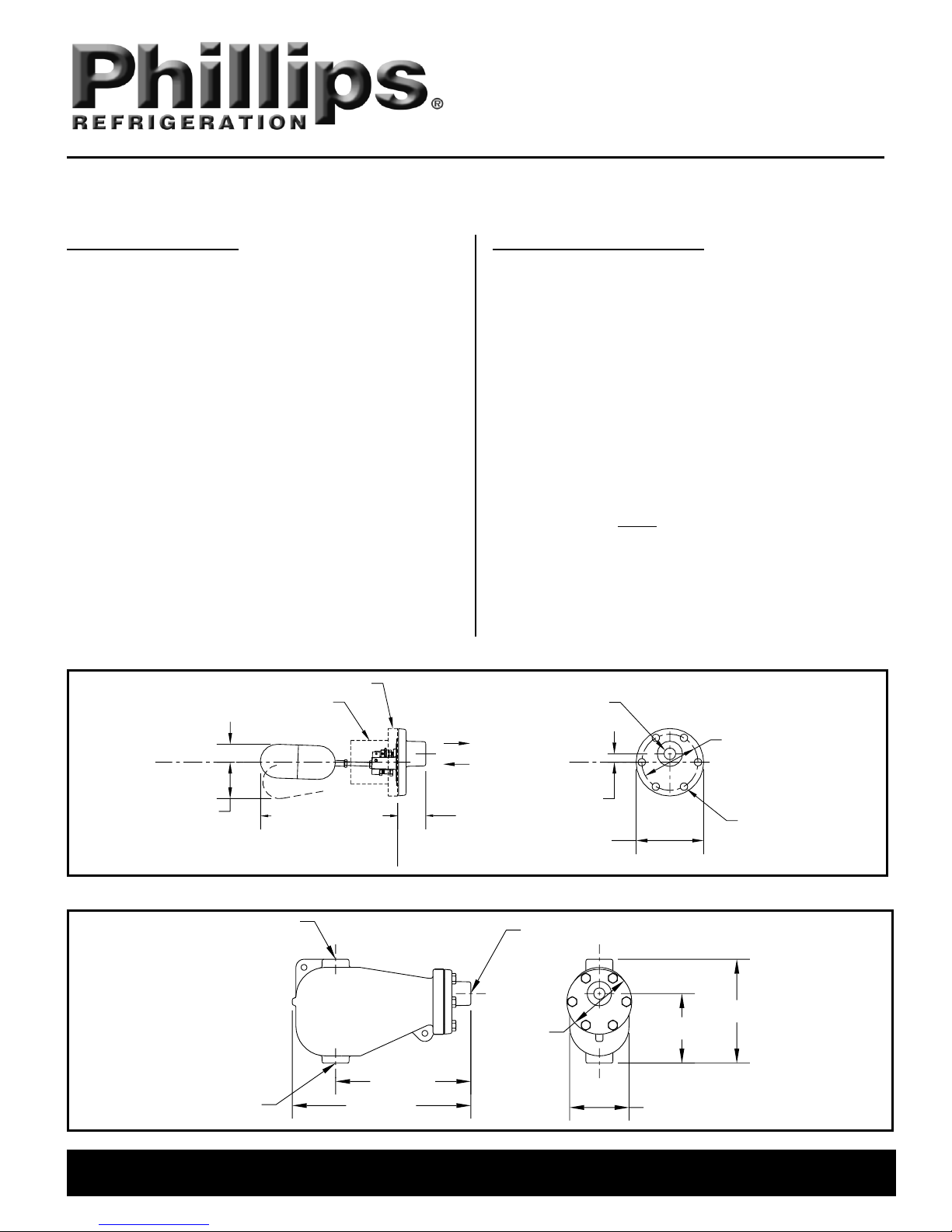
Figure 1: 275AP/APF/AF Valve without Chamber
INSTALLATION INSTRUCTIONS
The 275AF/AP/APF valves are available without a chamber
(Figure 1), with a cast iron chamber (Figure 2) or with a welded
steel chamber (Figure 3). An optional mounting flange is
available for mounting the valve without a chamber (Figure 4).
The valve should always be oriented such that the 1/2" FPT
connection is toward the top of the valve and the front face is
vertical. This will ensure that the float moves appropriately with
changes in liquid level.
The 275AP and APF valves are used as pilot float valves to
control a 700H series valve. The piping arrangement in Figure
5 shows a number of important details:
The float level should be at least 18 in. above the 700H
valve.
The pilot line MUST be either 3/8” OD copper tubing
(halocarbon applications) or 1/4” nominal pipe (halocarbon
or ammonia).
The pilot line should include a shut-off valve, pressure
gauge and gauge valve for troubleshooting. (See
Troubleshooting section, later in this bulletin.)
Figure 2: 275AP/APF/AF Valve with Cast Iron Chamber
275AP-SB13-01 1
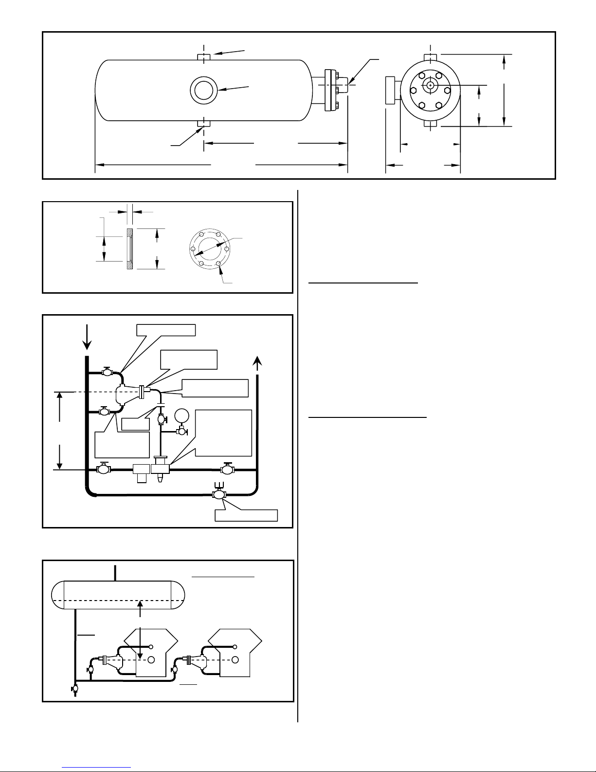
Figure 3: 275AP/APF/AF Valve with Steel Chamber
27.88 [708.0]
15.88 [403.2]
7.88 [200.0]
8.25 [209.6]
Ø6.63 [168.3]
4.50 [114.2]
3/4" FPT
1/2" FPT
LEVEL EYE ®
3/4" FPT
(6) 7/16-20 NF
0.63 [15.9]
Ø2.91 x .34DP
SOCKET
Ø3.75 [Ø95.3]
BC
Ø4.50 [114.3]
TO LOWER
PRESSURE
VESSEL
P
18 in.
MIN.
CONDENSER
DRAIN
UPPER EQ LINE
LOWER EQ LINE
(DO NOT TRAP
ON NH3)
MANUAL BYPASS
PILOT LINE
1/4” NOMINAL IPS
700H SERIES
PILOT
OPERATED
VALVE WITH
CLOSE-COUPLED
STRAINER
275AP/APF PILOT
FLOAT VALVE
UNION
OIL RECEIVER / STILL:
AT LEAST 2 FT HIGHER
ELEVATION THAN CRANK
CASE FOR GRAVITY FEED;
CAN BE AT SAME ELEVATION
AS CRANKCASE IF AT HIGHER
PRESSURE.
275AF: CHAMBER
EQUALIZED TO
CRANKCASE
275AF: CHAMBER
EQUALIZED TO
CRANKCASE
2 FT.
Figure 4: Optional Mounting Flange
Figure 5: 275AP/APF Piloting 700H Valve
Figure 6: 275AF Maintaining Oil Levels in Multiple
Compressor Crankcases
275AP-SB13-01 2
The 275AF valves may be used to maintain the oil level in one
or more compressor crankcases (Figure 6). Note that if the oil
reservoir level is less than 2 feet above the crankcase level, it
should be pressurized 5 to 20 psi (0.3 to 1.4 bar) higher than
the crankcase.
REPLACEMENT PARTS
Basic replacement parts are illustrated in Figure 7 and listed in
Table 1.
When contacting Phillips for replacement parts, have the
complete valve model and serial number (shown on the valve
nameplate) available to ensure you receive the correct
components. For example: “275APF-BZA” is a complete valve
model, and “990123” or “E-12345” are complete serial
numbers.
SERVICE INSTRUCTIONS
Lever pin / float block removal and replacement: If it is
necessary to remove the lever pin (411) and float block (230Z)
during servicing, first cut one end of the pin flush with the valve
body. Then either pull the pin out with pliers, or carefully drive it
out with a punch. Retain the spacers (11S) for re-assembly.
After re-assembly, peen the lever pin to retain in place and
check for free movement of valve components.
Needle and seat replacement: The needle and seat bushing
are lapped in the factory to create a matched set. If either the
needle or seat bushing show signs of wear or damage, both
parts must be replaced. To inspect or replace the needle and
seat perform the following steps.
1. Remove the lever pin and float block as described above.
2. Remove the old seat bushing and install a new one using
PTFE tape or other pipe sealant on the threads.
3. Remove the old needle from the adjusting nut (204E), lock
washer (55), and lock nut (224). Reassemble the nut and
washer loosely on the new needle.
4. Insert the new needle into the new bushing. Install the
float block / float assembly (without spacers) loosely in the
valve body with the lever pin. DO NOT PEEN THE LEVER PIN
AT THIS TIME.
(Continued on next page)
 Loading...