

PHILIPS 27G7, 29G7, 32G7, 26G7 Service Manual

IMPORTANT SAFETY NOTICE
Proper service and repair is important to the safe, reliable operation of all Philips
Consumer Electronics Company** Equipment. The service procedures recommended by
Philips and described in this service manual are effective methods of performing service
operations. Some of these service operations require the use of tools specially designed
for the purpose. The special tools should be used when and as recommended.
It is important to note that this manual contains various CAUTIONS and NOTICES
which should be carefully read in order to minimize the risk of personal injury to service
personnel. The possibility exists that improper service methods may damage the
equipment. It also is important to understand that these CAUTIONS and NOTICES
ARE NOT EXHAUSTIVE. Philips could not possibly know, evaluate and advise the
service trade of all conceivable ways in which service might be done, or of the possible
hazardous consequences of each way. Consequently, Philips has not undertaken any such
broad evaluation. Accordingly, a servicer who uses a service procedure or tool which is
not recommended by Philips must first satisfy himself thoroughly that neither his safety
nor the safe operation of the equipment will be jeopardized by the service method
selected.
** Hereafter throughout this manual, Philips Consumer Electronics Company will be
referred to as Philips.
WARNING
Critical components having special safety characteristics are identified with a or
"S" by the Ref. No. in the parts list and enclosed within a broken line* (where
several critical components are grouped in one area) along with the safety symbol
on the schematics or exploded views. Use of substitute replacement parts which
do not have the same specified safety characteristics may create shock, fire, or other
hazards. Under no circumstances should the original design be modified or altered
without written permission from Philips. Philips assumes no liability, express or
implied, arising out of any unauthorized modification of design. Servicer assumes all
liability.
* Broken Line ____ _ ____ _ ____ _ ____

FIRE AND SHOCK HAZARD
1. Be sure all components are positioned in such a way as to avoid the possibility of adjacent component
shorts. This is especially important on those chassis which are transported to and from the service shop.
2. Never release a repaired unit unless all protective devices such as insulators, barriers, covers, strain
reliefs, and other hardware have been installed in accordance with the original design.
3. Soldering and wiring must be inspected to locate possible cold solder joints, solder splashes, sharp solder
points, frayed leads, pinched leads, or damaged insulation (including the ac cord). Be certain to remove
loose solder balls and all other loose foreign particles.
4. Check across-the-line components and other components for physical evidence of damage or
deterioration and replace if necessary. Follow original layout, lead length, and dress.
5. No lead or component should touch a receiving tube or a resistor rated at 1 watt or more. Lead tension
around protruding metal surfaces or edges must be avoided.
6. Critical components having special safety characteristics are identified with an 'S' by the Ref. No. in the
parts list and enclosed within a broken line* (where several critical components are grouped in one area)
along with the safety symbol on the schematic diagrams and /or exploded views.
7. When servicing any unit, always use a separate isolation transformer for the chassis. Failure to use a
separate isolation transformer may expose you to possible shock hazard, and may cause damage to
servicing instruments.
8. Many electronic products use a polarized ac line cord (one wide pin on the plug). Defeating this safety
feature may create a potential hazard to the servicer and the user. Extension cords which do not
incorporate the polarizing feature should never be used.
9. After reassembly of the unit, always perform an ac leakage test or resistance test from the line cord to all
exposed metal parts of the cabinet. Also, check all metal control shafts (with knobs removed), antenna
terminals, handles, screws, etc., to be sure the unit may be safely operated without danger of electrical
shock.
* Broken line ____ _ ____ _ ____ _ ____

LEAKAGE CURRENT COLD CHECK
1. Unplug the ac line cord and connect a jumper between the two prongs of the plug.
2. Turn on the power switch.
3. Measure the resistance value between the jumpered ac plug and all exposed cabinet parts of the receiver,
such as screw heads, antennas, and control shafts. When the exposed metallic part has a return path to the
chassis, the reading should be between 1 megohm and 5.2 megohms. When the exposed metal does not
have a return path to the chassis, the reading must be infinity. Remove the jumper from the ac line cord.
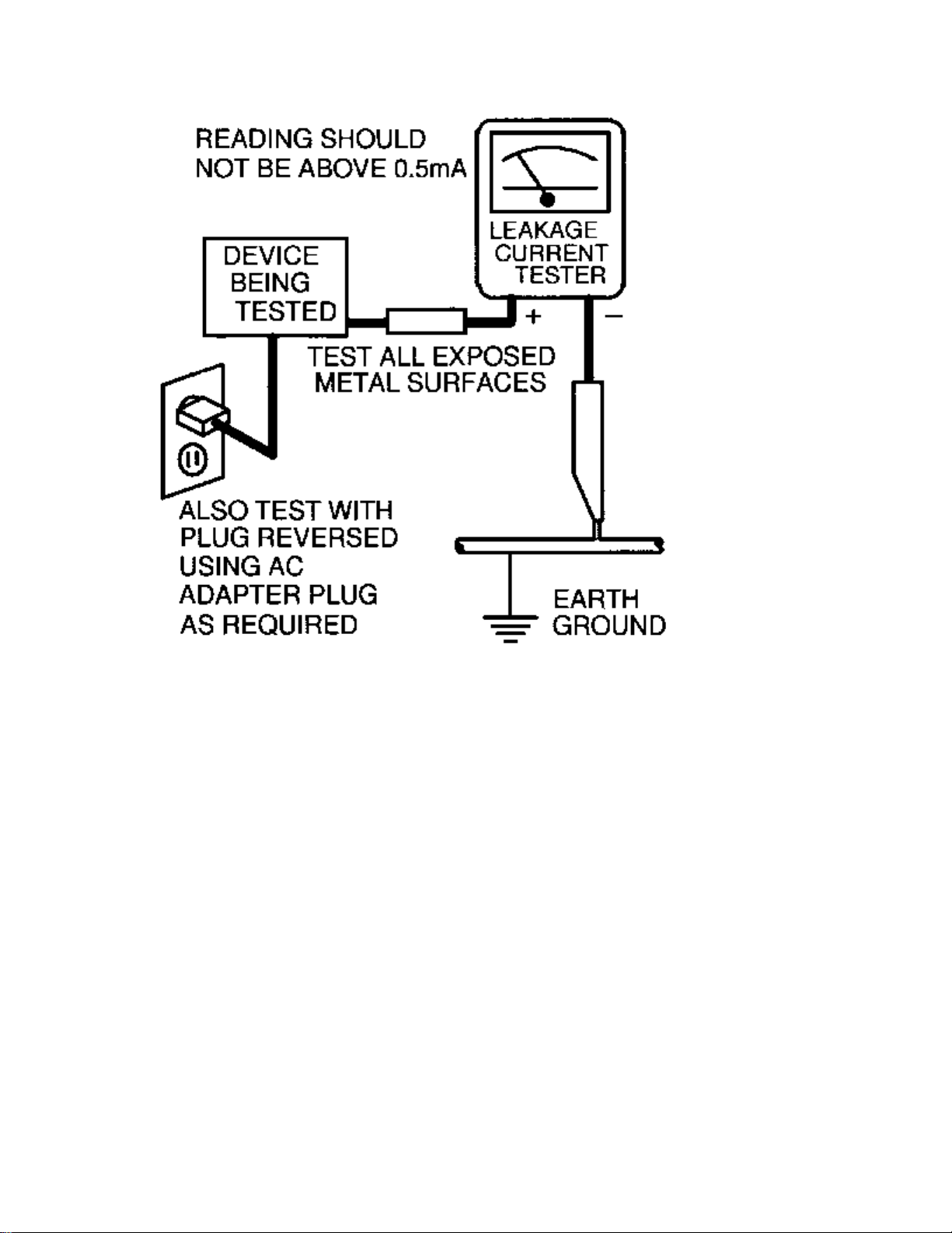
LEAKAGE CURRENT HOT CHECK
1. Do not use an isolation transformer for this test. Plug the completely reassembled receiver directly into
the ac outlet.
2. Connect a 1.5k, 10W resistor paralleled by a 0.15uF. capacitor between each exposed metallic cabinet
part and a good earth ground such as a water pipe, as shown below.
3. Use an ac voltmeter with at least 5000 ohms/volt sensitivity to measure the potential across the resistor.
4. The potential at any point should not exceed 0.75 volts. A leakage current tester may be used to make
this test; leakage current must not exceed 0.5mA. If a measurement is outside of the specified limits,
there is a possibility of shock hazard. The receiver should be repaired and rechecked before returning it
to the customer.
5. Repeat the above procedure with the ac plug reversed. (Note: An ac adapter is necessary when a
polarized plug is used. Do not defeat the polarizing feature of the plug.)
OR
With the instrument completely reassembled, plug the ac line cord directly into a 120Vac outlet. (Do not
use an isolation transformer during this test.) Use a leakage current tester or a metering system that
complies with American National Standards Institute (ANSI) C101.1 Leakage Current for Appliances and
Underwriters Laboratories (UL) 1410, (50.7). With the instrument ac switch first in the on position and
then in the off position, measure from a known earth ground (metal water pipe, conduit, etc.) to all exposed
metal parts of the instrument (antennas, handle brackets, metal cabinet, screw heads, metallic overlays,
control shafts, etc.), especially any exposed metal parts that offer an electrical return path to the chassis.
Any current measured must not exceed 0.5mA. Reverse the instrument power cord plug in the outlet and
repeat the test. See the graphic below.

TV SAFETY NOTES
SAFETY CHECKS
After the original service problem has been corrected, a complete safety check should be made. Be sure to
check over the entire set, not just the areas where you have worked. Some previous servicer may have left
an unsafe condition, which could be unknowingly passed on to your customer. Be sure to check all of the
following:
Fire and Shock Hazard
Implosion
X-Radiation
Leakage Current Cold Check
Leakage Current Hot Check
Picture Tube Replacement
Parts Replacement
WARNING: Before removing the CRT anode cap, turn the unit OFF and short the HIGH VOLTAGE to
the CRT DAG ground.
SERVICE NOTE: The CRT DAG is not at chassis ground.
IMPLOSION
1. All picture tubes used in current model receivers are equipped with an integral implosion system.
Care should always be used, and safety glasses worn, whenever handling any picture tube. Avoid
scratching or otherwise damaging the picture tube during installation.
2. Use only replacement tubes specified by the manufacturer.
X-RADIATION
1. Be sure procedures and instructions to all your service personnel cover the subject of X-radiation.
Potential sources of X-rays in TV receivers are the picture tube and the high voltage circuits. The
basic precaution which must be exercised is to keep the high voltage at the factory recommended
level.
2. To avoid possible exposure to X-radiation and electrical shock, only the manufacturer's specified
anode connectors must be used.
3. It is essential that the service technician has an accurate HV meter available at all times. The
calibration of this meter should be checked periodically against a reference standard.
4. When the HV circuitry is operating properly there is no possibility of an X-radiation problem. High
voltage should always be kept at the manufacturer's rated value - no higher - for optimum
performance. Every time a color set is serviced, the brightness should be run up and down while
monitoring the HV with a meter to be certain that the HV is regulated correctly and does not exceed
the specified value. We suggest that you and your technicians review test procedures so that HV and
HV regulation are always checked as a standard servicing procedure, and the reason for this prudent
routine is clearly understood by everyone. It is important to use an accurate and reliable HV meter. It
is recommended that the HV reading be recorded on each customer's invoice, which will
demonstrate a proper concern for the customer's safety.

5. When troubleshooting and making test measurements in a receiver with a problem of excessive high
voltage, reduce the line voltage by means of a Variac to bring the HV into acceptable limits while
troubleshooting. Do not operate the chassis longer than necessary to locate the cause of the excessive
HV.
6. New picture tubes are specifically designed to withstand higher operating voltages without creating
undesirable X-radiation. It is strongly recommended that any shop test fixture which is to be used
with the new higher voltage chassis be equipped with one of the new type tubes designed for this
service. Addition of a permanently connected HV meter to the shop test fixture is advisable. The
CRT types used in these new sets should never be replaced with any other types, as this may result in
excessive X-radiation.
7. It is essential to use the specified picture tube to avoid a possible X-radiation problem.
8. Most TV receivers contain some type of emergency "Hold Down" circuit to prevent HV from rising
to excessive levels in the presence of a failure mode. These various circuits should be understood by
all technicians servicing them, especially since many hold down circuits are inoperative as long as
the receiver performs normally.
PICTURE TUBE REPLACEMENT
The primary source of X-radiation in this television receiver is the picture tube. The picture tube
utilized in this chassis is specially constructed to limit X-radiation emissions. For continued Xradiation protection, the replacement tube must be the same type as the original, including suffix letter,
or a Philips approved type.
PARTS REPLACEMENT
Many electrical and mechanical parts in Philips television sets have special safety related
characteristics. These characteristics are often not evident from visual inspection nor can the protection
afforded by them necessarily be obtained by using replacement components rated for higher voltage,
wattage, etc. The use of a substitute part which does not have the same safety characteristics as the
Philips recommended replacement part shown in this service manual may create shock, fire, or other
hazards.
PRODUCT SAFETY GUIDELINES FOR ALL PRODUCTS
CAUTION: Do not modify any circuit. Service work should be performed only after you are thoroughly
familiar with all of the following safety checks. Risk of potential hazards and injury to the user increases if
safety checks are not adhered to.
USE A SEPARATE ISOLATION TRANSFORMER FOR THIS UNIT WHEN SERVICING.

PREVENTION OF ELECTROSTATIC DISCHARGE (ESD)
Some semiconductor solid state devices can be damaged easily by static electricity. Such components
commonly are called Electrostatically Sensitive (ES) Devices, Examples of typical ES devices are
integrated circuits and some field-effect transistors and semiconductor "chip" components. The following
techniques should be used to help reduce the incidence of component damage caused by electrostatic
discharge (ESD).
1. Immediately before handling any semiconductor component or semiconductor-equipped assembly, drain
off any ESD on your body by touching a known earth ground. Alternatively, obtain and wear a
commercially available discharging ESD wrist strap, which should be removed for potential shock
reasons prior to applying power to the unit under test.
2. After removing an electrical assembly equipped with ES devices, place the assembly on a conductive
surface such as aluminum foil, to prevent electrostatic charge buildup or exposure of the assembly.
3. Use only a grounded-tip soldering iron to solder or unsolder ES devices.
4. Use only an anti-static solder removal device. Some solder removal devices not classified as "antistatic
(ESD protected)" can generate an electrical charge sufficient to damage ES devices.
5. Do not use Freon propelled chemicals. These can generate electrical charges sufficient to damage ES
devices.
6. Do not remove a replacement ES device from its protective package until immediately before you are
ready to install it (most replacement ES devices are packaged with leads electrically shorted together by
conductive foam, aluminum foil or comparable conductive material).
7. Immediately before removing the protective material from the leads of a replacement ES device, touch
the protective material to the chassis or circuit assembly into which the device will be installed.
CAUTION: Be sure no power is applied to the chassis or circuit and observe all other safety precautions.
8. Minimize bodily motions when handling unpackaged replacement ES devices. (Otherwise harmless
motion such as the brushing together of your clothes fabric or the lifting of your feet from a carpeted
floor can generate static electricity (ESD) sufficient to damage an ES device.)
NOTE to CATV system Installer:
This reminder is provided to call the CATV system installer's attention to article 820-22 of the NEC that
provides guidelines for proper grounding and, in particular, specifies that the cable ground shall be
connected to the grounding system of the building, as close to the point of cable entry as practical.

PRACTICAL SERVICE PRECAUTIONS
IT MAKES SENSE TO AVOID EXPOSURE TO ELECTRICAL SHOCK. While some sources are
expected to have a possible dangerous impact, others of quite high potential are of limited current and are
sometimes held in less regard.
ALWAYS RESPECT VOLTAGES. While some may not be dangerous in themselves, they can cause
unexpected reactions – reactions that are best avoided. Before reaching into the powered color TV set, it is
best to test the high voltage insulation. It is easy to do, and is just a good service precaution.
BEFORE POWERING UP THE TV WITH THE BACK OFF (or on a test fixture), attach a clip lead to
the CRT DAG ground and to a screwdriver blade that has a well insulated handle. After the TV is powered
on and high voltage has developed, probe the anode lead with the blade, starting at the bottom of the High
Voltage Transformer (flyback – IFT). Move the blade to within two inches of the connector of the CRT. IF
THERE IS AN ARC, YOU FOUND IT THE EASY WAY, WITHOUT GETTING A SHOCK! If
there is an arc to the screwdriver blade, replace the High Voltage Transformer or the lead, (if removable)
whichever is causing the problem.
PICTURE TUBE REPLACEMENT PROCEDURE
Note: a. Two (2) people are required to handle this picture tube.
b. Safety Glasses must be worn during this procedure or whenever directly handling a picture tube.
c. Take care in each step not to damage the CRT or the cabinet.
1. Remove the Chassis and the CRT Socket Board Module from the cabinet.
2. A furniture pad or blanket should be positioned on the floor to support only the CRT Face. This pad or
blanket should be high enough to keep the CRT Face approximately 12 to 14 inches off the floor.
3. Using two people, place the cabinet in a front down position with the CRT Face on the pad or blanket.
4. Place padded blocks under each corner of the cabinet to keep it from rocking.
5. Remove the four screws, at the corners of the CRT.
6. With two people lowering the cabinet to the floor, leave the CRT elevated by the pad or blanket.
Note: Take care not to grasp the neck of the CRT during this procedure, as it is extremely fragile.
7. Two (2) people may then lift the CRT from the cabinet.
8. Remove the degaussing coil from the defective CRT and mount on the replacement. Take care to
maintain the exact shape and fit.
To install the new CRT, reverse steps 1 to 7.

GENERAL INFORMATION
CHASSIS SPECIFICATIONS
Channel Tuning:
Antenna: Channels 2 through 69
Cable: Channels 1 through 125
Allowable cable offset ± 2.0 MHz
Operating and Storage Temperatures:
Operating Temperature: 0ºC to +50ºC
Storage Temperature: -40ºC to +60ºC
Audio In/Out:
½ VRMS
System:
NTSC-M only
IF Frequencies:
45.75 Mhz picture, 41.25 MHz sound (intercarrier),
4.5 MHz sound IF
Sound Performance:
At 360 mv RMS/1 kHz to Audio input;
Output 8 Watt per channel with <10% Total Harmonic Distortion (THD).
At 1 Watt RMS, both channels driven, response is within ± 2dB from 20Hz to 20kHz.
Power Supply Voltages:
NAME VALUE TOLERANCE AT COMPONENT
VlotAux 1 18.8 volts +/- 3.5% 2663 (27“ and 32“ models)
VlotAux 1 12.5 volts +/- 3.5% 2663 (36“ models)
VlotAux 2 -14 volts +/- 3.5% 2664 (27“ and 32“ models)
VlotAux 2 -12.5 volts +/- 3.5% 2664 (36“ models)
VlotAux 3 210 volts +/- 5.5% 2656 (27“ and 32“ models)
VlotAux 3 200 volts +/- 5% 2656 (36“ models)
Vbat 130 volts +/- 1 volt 2917+
Vsound 13.5 volts +/- 1 volt 2925+
Vstby 5.1 volts +/- 0.1 volts 2938+
V+5v 5 volts +/- 0.2 volts 2937+
V+8v 8.3 volts +/- 0.2 volts 2931+
33V 33 volts +/- 2 volts 6955 cathode
200V 205 volts +5 volts/-35 volts Pin 2 of connector M60
These voltages are taken with a dummy load from Vbat to ground of 165 ohms.

Mains (AC Power):
60 Hz, 120 volts AC nominal:
Allowed 105 to 132 volts AC
For Auto-Multi-Voltage Only:
60 Hz, 120 to 247 volts AC
Power consumption, worst control setting:
1.6 Amps, 192 Watts
Standby power consumption:
<3 Watts +/-10%
High Voltage (EHT):
(At minimum brightness)
Screen Size: 27" 32" 36“
Voltage: 30.0kV +/- 1kV 30.0kV +/- 1kV 31.5kV +/- 1kV (for reference only)
Color Temperature:
NORMAL WARM COOL
10,500 +/- 10% 8,200 +/- 20% 14,000 +/- 20%
Note: Nominal specifications represent the design specifications. All units
should be able to approximate these. Some will exceed and some may
drop slightly below these specifications. Limit specifications represent
the absolute worst condition that still might be considered acceptable. In
no case should a unit fail to meet limit specifications.

MODEL TO MODULE LIST
The model to Module list shown below identifies all electrical panels, modules and assemblies used in each
model produced with the G7 chassis. This information was current at time of printing.
Information concerning cabinet parts and cabinet mounted parts (CRT/Yoke/etc.) is shown in the Cabinet
Replacement Parts List.
If you are attempting to service a model equipped with the G7 chassis, the necessary electrical information
should be covered in this service manual, even if the corresponding model number is not listed.
Model Size
Panel Number Description
Sub Panel Description
PHILIPS – MAGNAVOX MODELS
00TP2784-C1 27“
00AVJ245 Jack Panel (I/O Cinch Panel) (JP9110)
00A10783 Single PIP Panel
00EMG770 Main Chassis
00A10784 Comb Filter Panel
00TP2797-B1 27“
00AVJ246 Jack Panel (I/O Cinch Panel) (JP9115)
00A10782 2 Tuner Single PIP Panel
00EMG772 Main Chassis
00A10773 YUV Panel (Histogram)
00A10784 Comb Filter Panel
00TP3284-C1 32“
00AVJ245 Jack Panel (I/O Cinch Panel) (JP9110)
00A10783 Single PIP Panel
00EMG782 Main Chassis
00A10780 East West Panel (Diode Modulator)
00A10784 Comb Filter Panel
00TP3297-B1 32“
00AVJ246 Jack Panel (I/O Cinch Panel) (JP9115)
00A10782 2 Tuner Single PIP Panel
00EMG784 Main Chassis
00A10773 YUV Panel (Histogram)
00A10780 East West Panel (Diode Modulator)
00A10784 Comb Filter Panel

00TP3684-C1 36“
00AVJ245 Jack Panel (I/O Cinch Panel) (JP9110)
00A10783 Single PIP Panel
00EMG792 Main Chassis
00A10781 East West Panel (Diode Modulator)
00A10784 Comb Filter Panel
00TP3697-B1 36“
00AVJ246 Jack Panel (I/O Cinch Panel) (JP9115)
00A10782 2 Tuner Single PIP Panel
00EMG794 Main Chassis
00A10773 YUV Panel (Histogram)
00A10781 East West Panel (Diode Modulator)
00A10784 Comb Filter Panel
00TS3259-C1 32“
00AVJ244 Jack Panel (I/O Cinch Panel) (JP9110)
00EMG780 Main Chassis
00A10780 East West Panel (Diode Modulator)
00TS3659-C1 36“
00AVJ244 Jack Panel (I/O Cinch Panel) (JP9110)
00EMG790 Main Chassis
00A10781 East West Panel (Diode Modulator)
00A10785 Comb Filter Panel
PHILIPS GUIDE PLUS MODELS
0027PT40-B1 27“
00AVJ247 Jack Panel (I/O Cinch Panel) (JP9420)
00A10775 Virtual Dolby Panel
00A10776 Guide Plus Panel
00A10786 Double Window PIP Panel
00EMG774 Main Chassis
00A10774 YUV Panel (Histogram)
00A10785 Comb Filter Panel
0032PT70-B1 32“
00AVJ247 Jack Panel (I/O Cinch Panel) (JP9420)
00AVJ249 Side AV Panel
00A10775 Virtual Dolby Panel
00A10776 Guide Plus Panel
00A10786 Double Window PIP Panel
00EMG786 Main Chassis
00A10774 YUV Panel (Histogram)
00A10780 East West Panel (Diode Modulator)
00A10785 Comb Filter Panel

PHILIPS – MAGNAVOX CANADIAN MODELS
00XP2784-C1 36“
00AVJ245 Jack Panel (I/O Cinch Panel) (JP9110)
00A10783 Single PIP Panel
00EMG770 Main Chassis
00A10784 Comb Filter Panel
00XS3259-C1 32“
00AVJ244 Jack Panel (I/O Cinch Panel) (JP9110)
00EMG780 Main Chassis
00A10780 East West Panel (Diode Modulator)
00XS3659-C1 36“
00AVJ244 Jack Panel (I/O Cinch Panel) (JP9110)
00EMG790 Main Chassis
00A10781 East West Panel (Diode Modulator)
00A10785 Comb Filter Panel
PHILIPS - LATIN AMERICA MODELS
0033LL89-11 32“
00AVJ244 Jack Panel (I/O Cinch Panel) (JP9110)
00EMG783 Main Chassis
00A10780 East West Panel (Diode Modulator)
0037LP99-22 36“
00AVJ246 Jack Panel (I/O Cinch Panel) (JP9115)
00A10782 2 Tuner Single PIP Panel
00EMG791 Main Chassis
00A10773 YUV Panel (Histogram)
00A10781 East West Panel (Diode Modulator)
00A10784 Comb Filter Panel

PHILIPS - LATIN AMERICA - AMV MODELS
0029LP69-22 27“
00AVJ246 Jack Panel (I/O Cinch Panel) (JP9115)
00A10782 2 Tuner Single PIP Panel
00EMG771 Main Chassis
00A10773 YUV Panel (Histogram)
00A10784 Comb Filter Panel
0029LP69-32 27“
00AVJ246 Jack Panel (I/O Cinch Panel) (JP9115)
00A10782 2 Tuner Single PIP Panel
00EMG773 Main Chassis
00A10773 YUV Panel (Histogram)
00A10784 Comb Filter Panel
0033LP89-32 32“
00AVJ246 Jack Panel (I/O Cinch Panel) (JP9115)
00A10782 2 Tuner Single PIP Panel
00EMG781 Main Chassis
00A10773 YUV Panel (Histogram)
00A10780 East West Panel (Diode Modulator)
00A10784 Comb Filter Panel

Model to Remote Transmitter and Jack Panel Listing
Model
Number
0027PT40-B1
0029LP69-22
0029LP69-32
0032PT70-B1
0033LL89-11
0033LP89-32
0037LP99-22
00TP2784-C1
00TP2797-B1
00TP3284-C1
00TP3297-B1
00TP3684-C1
00TP3697-B1
00TS3259-C1
00TS3659-C1
00XP2784-C1 36“ RCU81B JP9110
00XS3259-C1 32“ RCU81BX JP9110
00XS3659-C1 36“ RCU81BX JP9110
Rear Connections of JP9110
Screen
Size
27“ RC2010/01 JP9420
27“ RCU81AX JP9115
27“ RCU81AX JP9115
32“ RC2010/01 JP9523
32“ RCU81BX/01 JP9110
32“ RCU81AX JP9115
36“ RCU81AX JP9115
27“ RCU81B JP9110
27“ RCU81E JP9115
32“ RCU81B JP9110
32“ RCU81E JP9115
36“ RCU81B JP9110
36“ RCU81E JP9115
32“ RCU81BX JP9110
36“ RCU81BX JP9110
Remote
Transmitter
Jack Panel
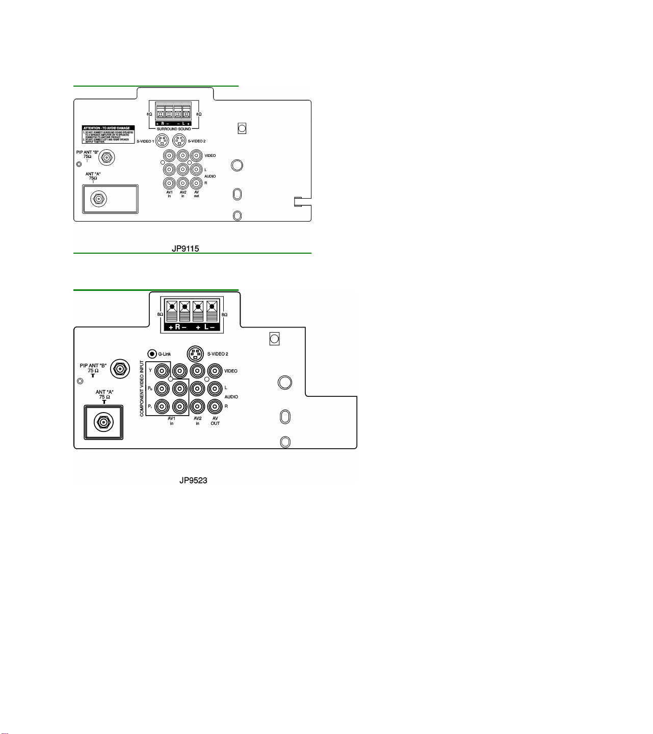
Rear Connections of JP9115
Rear Connections of JP9523
GLOSSARY OF TERMS, ACRONYMS, AND ABBREVIATIONS
2CS Two Channel Stereo
AFC Automatic Frequency Control
AFT Automatic Fine Tuning
AP Asia Pacific
ATS Automatic Tuning System
AV External Audio/Video
AVL Automatic Volume Level control
BTSC Broadcast Television Standard Committee (TV stereo)
CBA Circuit Board Assembly (PCB)
CC Closed Captioning

CSM Customer Service Mode
CVBS Color Video Blanking Sync
DNR Dynamic Noise Reduction
EEPROM Electrical Erasable Programmable Read-Only Memory
Error Buffer Register that keeps track of errors that occur and stores error codes
Error Code A numerical value used to indicate a failure in the television
EU Europe
EXT External audio/video input
FM Frequency Modulation
I²C Inter IC bus, 2-wire bi-directional (SCL/SDA)
ID Identification
IDENT Horizontal coincidence signal, transmitter identification
IF Intermediate Frequency
IN ITT sound IC with NICAM function
IT ITT sound IC without NICAM function
LATAM Latin America
LED Light Emit ting Diode
Local Keyboard The buttons (usually volume up, volume down, channel up, and channel down) located on
the front of the television set
MA Mono All; single mono carrier receiver
NICAM Near Instantaneous Companding Audio Multiplex; Digital Sound System
NR Noise Reduction
NTSC National Television Systems Committee (video)
NVM Non Volatile Memory
OB Option Byte (Feature Byte)
OSD On Screen Display
PCB Printed Circuit Board (CBA)
PIP Picture In Picture
PLL Phase Locked Loop
PP Personal Preference
RAM Random Access Memory
RC Remote Control
RC-5 Remote Control System 5
RGB Red Green Blue
ROM Read Only Memory
SAM Service Alignment Mode
SAP Second Audio Program
SCL Serial Clock
SDA Serial Data
SDM Service Default Mode
SVHS Super Video Home System
Top Level Menu This refers to the main menu (as opposed to sub menus) in SAM
V-Chip Violence-Chip
VCR Video Cassette Recorder
Y/C Luminance/Chrominance (video)
G7 CHASSIS FEATURE WORDS
Instrument
Assembly
mitter
A/B
Control
Standby
Volume L
No Picture
Inputs
16 x 9
Service Mode
Reduction
14 x 9
Str A/V
Tuning
Mode
Picture
Control
Lock
Un-Rated
No Rating
Chart No. Final Chassis Trans- Antenna Audio Auto Auto Auto Standby Muliple A/V Compress Customer Dynamic Noise Expand Mono Fine Hospitality Incredible PIP Parental
AB AD AK AL AN AV CM CS DN EX FM FT HO IP PI PL Feature Byte Values
27A950/37R TP2784C1 EMG770 RCU81B 0 1 0 1 0 1 0 1 1 0 0 1 0 0 1 1 85 147 47 188 0 0 0
27A950/35R XP2784C1 EMG770 RCU81B 0 1 0 1 0 1 0 1 1 0 0 1 0 0 1 1 85 147 47 188 0 0 0
27A985/37R TP2797B1 EMG772 RCU81E 1 1 0 1 0 1 0 1 1 0 0 1 0 1 1 1 213 151 239 188 0 0 0
27A975/85R 29LP6922 EMG771 RCU81AX 1 1 0 1 0 1 0 1 1 0 0 1 0 1 1 1 213 151 141 160 0 0 0
27A976/87R 29LP6932 EMG773 RCU81AX 1 1 0 1 0 1 0 1 1 0 0 1 0 1 1 1 213 151 141 160 0 0 0
32A940/37R TS3259C1 EMG780 or EMG785 RCU81BX 0 1 0 1 0 1 0 1 1 0 0 1 0 0 0 1 85 145 46 188 0 0 0
32A940/35R XS3259C1 EMG780 or EMG785 RCU81BX 0 1 0 1 0 1 0 1 1 0 0 1 0 0 0 1 85 145 46 188 0 0 0
32A950/37R TP3284C1 EMG782 or EMG787 RCU81B 0 1 0 1 0 1 0 1 1 0 0 1 0 0 1 1 85 147 47 188 0 0 0
32A985/37R TP3297B1 EMG784 or EMG788 RCU81E 1 1 0 1 0 1 0 1 1 0 0 1 0 1 1 1 213 151 239 188 0 0 0
32A960/85R 33LL8911 EMG783 or EMG710 RCU81BX 0 1 0 1 0 1 0 1 1 0 0 1 0 0 0 1 85 145 12 160 0 0 0
32A976/87R 33LP8932 EMG781 or EMG789 RCU81AX 1 1 0 1 0 1 0 1 1 0 0 1 0 1 1 1 213 151 141 160 0 0 0
36A940/37R TS3659C1 EMG790 or EMG796 RCU81BX 0 1 0 1 0 1 0 1 1 0 0 1 0 0 0 1 85 145 47 188 0 0 0
36A940/35R XS3659C1 EMG790 or EMG796 RCU81BX 0 1 0 1 0 1 0 1 1 0 0 1 0 0 0 1 85 145 47 188 0 0 0
36A950/37R TP3684C1 EMG792 or EMG798 RCU81B 0 1 0 1 0 1 0 1 1 0 0 1 0 0 1 1 85 147 47 188 0 0 0
36A985/37R TP3697B1 EMG794 or EMG799 RCU81E 1 1 0 1 0 1 0 1 1 0 0 1 0 1 1 1 213 151 239 188 0 0 0
36A975/85R 37LP9922 EMG791 or EMG797 RCU81AX 1 1 0 1 0 1 0 1 1 0 0 1 0 1 1 1 213 151 141 160 0 0 0
EEPROM ADR 3 b7 3 b6 3 b5 3 b4 3 b3 3 b2 3 b1 3 b0 4 b7 4 b6 4 b5 4 b4 4 b3 4 b2 4 b1 4 b0 Byte # 3 4 5 6 7 8 9
Chart No. Final Chassis Trans- PIP Remote Smart Number Speaker Auto Stby First Time Comb Incred. Pix Sync Timer V-Chip V-Chip V-Chip
Instrument Assembly mitter Tuner Locator Clock of A/Vs On/Off Auto On Setup Filter Via Menu Slice L. On/Off Un-Rated No Rating
PT RL SC SO SP ST SU CF IM VS TM VC VU VN
27A950/37R TP2784C1 EMG770 RCU81B 0 0 1 0 1 1 1 1 1 0 1 1 1 1
EEPROM ADR 5 b7 5 b6 5 b5 5 b4 5 b3 5 b2 5 b1 5 b0 6 b7 6 b6 6 b5 6 b4 6 b3 6 b2
27A950/35R XP2784C1 EMG770 RCU81B 0 0 1 0 1 1 1 1 1 0 1 1 1 1
27A985/37R TP2797B1 EMG772 RCU81E 1 1 1 0 1 1 1 1 1 0 1 1 1 1
27A975/85R 29LP6922 EMG771 RCU81AX 1 0 0 0 1 1 0 1 1 0 1 0 0 0
27A976/87R 29LP6932 EMG773 RCU81AX 1 0 0 0 1 1 0 1 1 0 1 0 0 0
32A940/37R TS3259C1 EMG780 or EMG785 RCU81BX 0 0 1 0 1 1 1 0 1 0 1 1 1 1
32A940/35R XS3259C1 EMG780 or EMG785 RCU81BX 0 0 1 0 1 1 1 0 1 0 1 1 1 1
32A950/37R TP3284C1 EMG782 or EMG787 RCU81B 0 0 1 0 1 1 1 1 1 0 1 1 1 1
32A985/37R TP3297B1 EMG784 or EMG788 RCU81E 1 1 1 0 1 1 1 1 1 0 1 1 1 1
32A960/85R 33LL8911 EMG783 or EMG710 RCU81BX 0 0 0 0 1 1 0 0 1 0 1 0 0 0
32A976/87R 33LP8932 EMG781 or EMG789 RCU81AX 1 0 0 0 1 1 0 1 1 0 1 0 0 0
36A940/37R TS3659C1 EMG790 or EMG796 RCU81BX 0 0 1 0 1 1 1 1 1 0 1 1 1 1
36A940/35R XS3659C1 EMG790 or EMG796 RCU81BX 0 0 1 0 1 1 1 1 1 0 1 1 1 1
36A950/37R TP3684C1 EMG792 or EMG798 RCU81B 0 0 1 0 1 1 1 1 1 0 1 1 1 1
36A985/37R TP3697B1 EMG794 or EMG799 RCU81E 1 1 1 0 1 1 1 1 1 0 1 1 1 1
36A975/85R 37LP9922 EMG791 or EMG797 RCU81AX 1 0 0 0 1 1 0 1 1 0 1 0 0 0
Chart No. Final Chassis Trans- Antenna Audio Auto Auto Auto Standby Muliple A/V Compress Customer Dynamic Noise Expand Mono Fine Hospitality Incredible PIP Parental
Instrument Assembly mitter A/B Control Standby Volume L No Picture Inputs 16 x 9 Service Mode Reduction 14 x 9 Str A/V Tuning Mode Picture Control Lock
AB AD AK AL AN AV CM CS DN EX FM FT HO IP PI PL Feature Byte Values
27FSQ985/37R 27PT40B1 EMG774 RC2010 1 1 0 1 0 1 0 1 1 0 0 0 0 1 1 1 213 135 175 222 224 0 0
EEPROM ADR 3 b7 3 b6 3 b5 3 b4 3 b3 3 b2 3 b1 3 b0 4 b7 4 b6 4 b5 4 b4 4 b3 4 b2 4 b1 4 b0 Byte # 3 4 5 6 7 8 9
32FSQ985/37R 32PT70B1 EMG786 RC2010 1 1 0 1 0 1 0 1 1 0 0 0 0 1 1 1 213 135 191 222 224 0 0
Chart No. Final Chassis Trans- PIP Remote Smart Number Speaker Auto Stby First Time Comb Incred. Pix Virtual Sync Timer D Window D Window Guide Go to
Instrument Assembly mitter Tuner Locator Clock of A/Vs On/Off Auto On Setup Filter Via Menu Dolby Slice L. 4:3 16:9 Plus Guide+
PT RL SC SO SP ST SU CF IM VD VS TM W1 W2 GP GG
27FSQ985/37R 27PT40B1 EMG774 RC2010 1 0 1 0 1 1 1 1 1 1 0 1 1 1 1 0
EEPROM ADR 5 b7 5 b6 5 b5 5 b4 5 b3 5 b2 5 b1 5 b0 6 b7 6 b6 6 b5 6 b4 6 b3 6 b2 6 b1 6 b0
32FSQ985/37R 32PT70B1 EMG786 RC2010 1 0 1 1 1 1 1 1 1 1 0 1 1 1 1 0
Chart No. Final Chassis Trans- V-Chip V-Chip V-Chip Expand
Instrument Assembly mitter On/Off
4:3
VC VU VN EP
27FSQ985/37R 27PT40B1 EMG774 RC2010 1 1 1 0
EEPROM ADR 7 b7 7 b6 7 b5 7 b4
32FSQ985/37R 32PT70B1 EMG786 RC2010 1 1 1 0
G7 Chassis Feature Listing
Model
Chassis
Trans-
Rear
Side
Head
Top
AMV
Diode
Guide +
PIP
Clock
Histogram/
Color
Blue
Comb
Var/Fix
Tone
Virtual
Surround
Incredible
AVL
Surf
Remote
Sub-
Audio
Bimos
Number
Assembly
mitter
Jacks
A/V
phone
Control
Modulator
Gold
LTI
Temperature
Stretch
Filter
A-Out
Control
Dolby
Jacks
Surround
Locator
Woofer
27PT40B101
EMG774
RC20-STIK
JP9420 -AVJ247
front A10776
D Window PIP- A10786
SMT
A10774
XXA10785
XXA10775
XXX
SMT 2x8W DBX Str
TDA8847
TP2784C101
EMG770
RCU81B
JP9110 -AVJ245
S-PIP - A10783
SMTXX
A10784
XXXXSMT
2x5W DBX Str
TDA8846
TP2797B101
EMG772
RCU81E
JP9115 -AVJ246
S-PIP 2 Tuner - A10782
SMT
A10773
XXA10784
XXXXX
SMTX2x5W DBX Str
TDA8847
XP2784C101
EMG770
RCU81B
JP9110 -AVJ245
S-PIP - A10783
SMTXX
A10784
XXXXSMT
2x5W DBX Str
TDA8846
29LP692201
EMG771
RCU81AX
JP9115 -AVJ246
S-PIP 2 Tuner - A10782
X
A10773
XXA10784
XX X XSMT 2x5W DBX Str
TDA8847
29LP693201
EMG773
RCU81AX
JP9115 -AVJ246
X
S-PIP 2 Tuner - A10782
X
A10773
XXA10784
XX X XSMT 2x5W DBX Str
TDA8847
32PT70B101
EMG786
RC20-STIK
JP9523 -AVJ247
AVJ249
sideXA10780
A10776
D Window PIP- A10786
SMT
A10774
XXA10785
XXA10775
XXX
SMT 5W
2x5W DBX Str
TDA8847
TP3284C101
EMG782
RCU81B
JP9110 -AVJ245
A10780
S-PIP - A10783
SMTXX
A10784
XX XX
SMT 2x5W DBX Str
TDA8847
TP3284C102
EMG787
RCU81B
JP9110 -AVJ245
A10780
S-PIP - A10783
SMTXX
A10784
XX XX
SMT 2x5W DBX Str
TDA8847
TP3297B101
EMG784
RCU81E
JP9115 -AVJ246
A10780
S-PIP 2 Tuner - A10782
SMT
A10773
XXA10784
XX XXXSMTX2x5W DBX Str
TDA8847
TP3297B102
EMG788
RCU81E
JP9115 -AVJ246
A10780
S-PIP 2 Tuner - A10782
SMT
A10773
XXA10784
XX XXXSMTX2x5W DBX Str
TDA8847
TS3259C101
EMG780
RCU81BX
JP9110 -AVJ244
A10780
SMTXX
PAL-DL
XX XX
SMT
2x5W DBX Str
TDA8843
TS3259C102
EMG785
RCU81BX
JP9110 -AVJ244
A10780
SMTXX
PAL-DL
XX XX
SMT
2x5W DBX Str
TDA8843
XS3259C101
EMG780
RCU81BX
JP9110 -AVJ244
A10780
SMTXX
PAL-DL
XX XX
SMT
2x5W DBX Str
TDA8843
XS3259C102
EMG785
RCU81BX
JP9110 -AVJ244
A10780
SMTXX
PAL-DL
XX XX
SMT
2x5W DBX Str
TDA8843
33LL891101
EMG783
RCU81BX/01
JP9110 -AVJ244
X
A10780
XXXPAL-DL
XX XX
SMT
2x5W DBX Str
TDA8843
33LL891102
EMG710
RCU81BX/01
JP9110 -AVJ244
X
A10780
XXXPAL-DL
XX XX
SMT
2x5W DBX Str
TDA8843
33LP893201
EMG781
RCU81AX
JP9115 -AVJ246
X
A10780
S-PIP 2 Tuner - A10782
X
A10773
XXA10784
XX XXXSMT 2x5W DBX Str
TDA8847
33LP893202
EMG789
RCU81AX
JP9115 -AVJ246
X
A10780
S-PIP 2 Tuner - A10782
X
A10773
XXA10784
XX XXXSMT 2x5W DBX Str
TDA8847
37LP992201
EMG791
RCU81AX
JP9115 -AVJ246
A10781
S-PIP 2 Tuner - A10782
X
A10773
XXA10784
XX XXXSMT 2x5W DBX Str
TDA8847
37LP992202
EMG797
RCU81AX
JP9115 -AVJ246
A10781
S-PIP 2 Tuner - A10782
X
A10773
XXA10784
XX XXXSMT 2x5W DBX Str
TDA8847
TP3684C101
EMG792
RCU81B
JP9110 -AVJ245
A10781
S-PIP - A10783
SMTXX
A10784
XX XX
SMT 2x5W DBX Str
TDA8847
TP3684C102
EMG798
RCU81B
JP9110 -AVJ245
A10781
S-PIP - A10783
SMTXX
A10784
XX XX
SMT 2x5W DBX Str
TDA8847
TP3697B101
EMG794
RCU81E
JP9115 -AVJ246
A10781
S-PIP 2 Tuner - A10782
SMT
A10773
XXA10784
XX XXXSMTX2x5W DBX Str
TDA8847
TP3697B102
EMG799
RCU81E
JP9115 -AVJ246
A10781
S-PIP 2 Tuner - A10782
SMT
A10773
XXA10784
XX XXXSMTX2x5W DBX Str
TDA8847
TS3659C101
EMG790
RCU81BX
JP9110 -AVJ244
A10781
SMTXX
A10785
XX XX
SMT
2x5W DBX Str
TDA8847
TS3659C102
EMG796
RCU81BX
JP9110 -AVJ244
A10781
SMTXX
A10785
XX XX
SMT
2x5W DBX Str
TDA8847
XS3659C101
EMG790
RCU81BX
JP9110 -AVJ244
A10781
SMTXX
A10785
XX XX
SMT
2x5W DBX Str
TDA8847
XS3659C102
EMG796
RCU81BX
JP9110 -AVJ244
A10781
SMTXX
A10785
XX XX
SMT
2x5W DBX Str
TDA8847
Model
Chassis
Comb
Var/Fix
Tone
Virtual
Surround
Incredible
Number
Assembly
Filter
A-Out
Control
Dolby
Jacks
Surround
27PT40B101 EMG774 A10785 X X A10775 X X
XS3659C102
EMG796
A10785
XX
X
TP2784C101 EMG770 A10784 X X X
TP2797B101 EMG772 A10784 X X X X
XP2784C101 EMG770 A10784 X X X
29LP692201 EMG771 A10784 X X X
29LP693201 EMG773 A10784 X X X
32PT70B101 EMG786 A10785 X X A10775 X X
TP3284C101 EMG782 A10784 X X X
TP3284C102 EMG787 A10784 X X X
TP3297B101 EMG784 A10784 X X X X
TP3297B102 EMG788 A10784 X X X X
TS3259C101 EMG780 PAL-DL X X X
TS3259C102 EMG785 PAL-DL X X X
XS3259C101 EMG780 PAL-DL X X X
XS3259C102 EMG785 PAL-DL X X X
33LL891101 EMG783 PAL-DL X X X
33LL891102 EMG710 PAL-DL X X X
33LP893201 EMG781 A10784 X X X X
33LP893202 EMG789 A10784 X X X X
37LP992201 EMG791 A10784 X X X X
37LP992202 EMG797 A10784 X X X X
TP3684C101 EMG792 A10784 X X X
TP3684C102 EMG798 A10784 X X X
TP3697B101 EMG794 A10784 X X X X
TP3697B102 EMG799 A10784 X X X X
TS3659C101 EMG790 A10785 X X X
TS3659C102 EMG796 A10785 X X X
XS3659C101 EMG790 A10785 X X X
AVL
Surf
Remote
Sub-
Audio
Bimos
Locator
Woofer
X SMT 2x8W DBX Str TDA8847
X
SMT
2x5W DBX Str
TDA8847
X SMT 2x5W DBX Str TDA8846
X SMT X 2x5W DBX Str TDA8847
X SMT 2x5W DBX Str TDA8846
X SMT 2x5W DBX Str TDA8847
X SMT 2x5W DBX Str TDA8847
X SMT 5W 2x5W DBX Str TDA8847
X SMT 2x5W DBX Str TDA8847
X SMT 2x5W DBX Str TDA8847
X SMT X 2x5W DBX Str TDA8847
X SMT X 2x5W DBX Str TDA8847
X SMT 2x5W DBX Str TDA8843
X SMT 2x5W DBX Str TDA8843
X SMT 2x5W DBX Str TDA8843
X SMT 2x5W DBX Str TDA8843
X SMT 2x5W DBX Str TDA8843
X SMT 2x5W DBX Str TDA8843
X SMT 2x5W DBX Str TDA8847
X SMT 2x5W DBX Str TDA8847
X SMT 2x5W DBX Str TDA8847
X SMT 2x5W DBX Str TDA8847
X SMT 2x5W DBX Str TDA8847
X SMT 2x5W DBX Str TDA8847
X SMT X 2x5W DBX Str TDA8847
X SMT X 2x5W DBX Str TDA8847
X SMT 2x5W DBX Str TDA8847
X SMT 2x5W DBX Str TDA8847
X SMT 2x5W DBX Str TDA8847

G7 CHASSIS SERVICE ADJUSTMENTS
REQUIRED TOOLS FOR SERVICING
Isolation Transformer
Multimeter
Oscilloscope
High Voltage (100:1) Oscilloscope Probe
Sencore VG91 Universal Video Generator
Caution: The G7 chassis incorporates a ”hot“ ground system. Always use a separate isolation
transformer when applying power to the exposed chassis.
Service Adjustment Notes:
Unless Otherwise Specified:
1. All service adjustments are ”hot“ voltagewise. For maximum safety, ensure the use of properly insulated
tools.
2. Refer to the G7 Main Chassis Printed Circuit Board for location of test points and adjustable components.
3. Grid Locations (Ex.: D-2) next to the reference numbers for components refer to the Main Chassis Printed
Circuit Board.
Focus Adjustment
1. Tune the set to a local or cable station.
2. Adjust the Focus Control (located on the upper part of the flyback transformer) for best picture details at
high light conditions.
Degaussing the Television
1. Position the television so that the screen faces the direction it will be facing when in use.
2. Ensure the television is turned off.
3. Move a degaussing coil in a circular motion slowly around the sides and front of the television.
4. Withdraw the degaussing coil at least six feet from the television before disconnecting it from its power
source.

G7 SERVICE MODES
Introduction
1. There are three service modes used in the G7 chassis. They are:
a. SAM - Service Alignment Mode
b. SDM - Service Default Mode
c. CSM - Customer Service Mode
2. The Service Alignment Mode corresponds to the older "Service Mode". The SAM allows
adjustments/alignments, setting of options, writing defaults to the memory IC, and erasing error codes.
This mode also displays the Run Timer, the Software Version, and current option settings.
3. The Service Default Mode is a technical aid for the service technician. It establishes a fixed, repeatable
setting of controls to allow measurements to be made. On screen display is kept at a minimum to reduce
the cluttering of wave forms with unwanted information.
4. The Customer Service Mode shows error codes and information on the TV operation settings. The servicer
can instruct the customer to enter CSM by telephone and read off the information displayed. This helps the
servicer to diagnose problems and failures in the TV set before making a service call.
5. Each of these Service Modes displays their acronym (SAM, SDM, or CSM) in the upper right hand corner
of the screen when they are active.
6. It will be memorized in the NVM that the TV set is in SDM or SAM. This is necessary because the TV must
show up in SDM or SAM again after an ac power interrupt.
7. When the television is in SAM or SDM, all normal features (such as volume control and direct channel
access) are available.
Service unfriendly modes
In the service modes, a number of modes/features are ignored since they interfere with diagnosing or repairing
a set. These are ”service unfriendly modes.“
”Ignoring“ means that the event that is triggered is not executed; the setting remains unchanged (Example:
Timer OFF: 8:00 PM; the set will not switch OFF in service mode at 8:00PM, but the setting will remain).
The service unfriendly modes are:
• Timer
• Sleep timer
• Hospitality mode
• Auto switch off (when there is no video signal identified)
• Smart lock or blocking by V-chip
• Skipped Channels
• Closed Captioning

SERVICE ALIGNMENT MODE (SAM)
S A M
0
0
0
0
1. The Service Alignment Mode (SAM) is used to set the option codes and bytes of the set, and display the
error codes (the Power LED begins blinking procedure for error code display, if errors are detected). SAM
also overrides software protections.
2. To enter the Service Alignment Mode, press the following key sequence on the remote control transmitter:
0-6-2-5-9-6-Status
Do not allow the display to time out between entries while keying the sequence.
SAM can also be entered by pressing the Channel Down and Volume Down keys on the local keyboard
simultaneously while in SDM mode.
When Service Alignment Mode is entered, the text "SAM" will be displayed in the upper right corner of the
screen.
3. When Service Alignment Mode is entered, the Power LED will begin blinking to display any detected error
codes, and service unfriendly modes are disabled. All customer controls are set to predetermined values.
4. When the unit is operating in Service Alignment Mode, all normal on-screen displays are suppressed and
replaced by a special service display. The first screen seen upon entering SAM is the ”top level SAM
menu.“ The service technician must return to the top level SAM menu before exiting with a power-off
command.
A sample top level SAM menu display is shown below.
0019 A81US1–1. 2
ERR 14 0
OPT 85 139 47 222 224 0 0
GUIDE PLUS TEST
ERASE BUFFER
OPTIONS
5. To select a sub-menu from the top level SAM menu, use the Menu Up or Menu Down keys on the remote
control to highlight the sub-menu.
6. To enter the selected sub-menu, use the Menu Left/Right keys on the remote control.
7. When the Menu button is pressed in a lower level Menu (or sub-menu), the software will switch back to the
next higher level menu.
8. Press the Status button on the remote control to toggle the OSD ON and OFF.
9. From the top level SAM menu, press the Menu button on the remote control to switch the software to a
Virtual Customer Mode; the text "SAM" will still be displayed in the upper right corner of the screen. In this
mode, all customer menu adjustments to the set can be made. From the Virtual Customer Mode, press the
Menu button to return to the top level SAM menu display.

10. To exit the Service Alignment Mode and erase the error codes, turn the unit off with the Power button on
the remote control or the local keyboard, then unplug the ac cord.
11. To exit the Service Alignment Mode and save the error codes, unplug the ac cord to turn off the set. When
the set is turned on again, the Service Alignment Mode will still be active.
Explanation of Display:
Run Timer
The first set of characters (0019 in the example) is a run timer. The run timer counts the normal operation hours,
but does not count standby hours. The run timer displays hours in hexadecimal format. The value of the run
timer is displayed in SAM and CSM. This display will increment based on the amount of time the set has been
on. The display will also be incremented one hour each time the set is turned on.
Software Identification, Cluster, and Version
The software identification, cluster, and version will be shown in the top level SAM menu, and in CSM.
The following format will be used: ”AAABBC-X.Y“. (Example: A81US1 1.2)
− AAA is the engineering project name (Ex: A81 = A8.1).
− BB is additional specification indicating specific functionality or a region (Ex: US). Processors with the same
engineering project name and function name are interchangeable, except for the languages they support.
− C is the language cluster number within the ”BB“ software version (Ex: 1 = English/Spanish/French)
− X is the main version number (Ex: 1)
− Y is the sub version number (Ex: 2)
− the main version number is updated with a major change of specification (incompatible with the previous
software version)
− the sub version number is updated with a minor change (backwards compatible with the previous versions)
− Note: A new micro controller is considered to be compatible if it works instead of the old software and the
functionality is not significantly changed.

Error Buffer
The six most recent errors are encoded on the following line of the display. The most recent error will be
displayed in the register nearest the text ”ERR.“ The error codes and their meanings are shown below.
Error Code Table
0 = No error
1 = X-ray protection, E/W protection and/or Vertical protection active
2 = High beam current protection active
3 = Reserved
4 = +5V protection active
5 = Signal Processor (IC 7150) register corrupted
6 = Signal Processor (IC 7150) error
7
8 = Internal RAM error (Microprocessor IC 7000)
9
10 = NV memory (IC 7088) addressing error
11 = NV memory (IC 7088) identification error
12 = Histogram (YUV) (IC 7330) error (TDA9178)
14
15
16 = ALPS Tuner I²C error (IC 1125)
17 = PIP Processor I²C error (IC 7350)
18 = PIP Tuner I²C error (IC 1127)
19
20
21
22
23
Note: I²C = (SCL/SDA)
The error buffer will automatically be erased if its contents haven't changed in the last 50 hours of use (run timer
count). This is to prevent an error buffer full of codes which are not valid.
Manual erasure of the buffer is possible through:
To save error codes, remove ac power. When ac power is reapplied, the chassis will be on, in SAM or SDM,
and the error codes may be viewed again.
A blinking LED may indicate a current error. The error code can be determined by counting the "off" blinks.
= General I2C error
= OSD generator I2C error (PCA 8516 )
= Sound processor I2C error (IC 7430) (MSP3430)
= I/O expander I2C error (PCF8674 for DW)
= EPG I2C error or Guide Plus I2C error
= Non Volatile Clock I2C error
= I/O Expander I2C error (PCF8574 for I/O panel)
= Virtual Dolby I2C error (DPL3518)
= Reserved (for 2nd Painter)
l ERASE BUFFER (SAM mode only) command from the remote control
l exiting SDM or SAM by pressing the Power button on the remote control or the television set

Reading Error Codes
Error codes are displayed in the following ways:
1. By SAM, SDM, or CSM display
2. By blinking Power LED
1. If the on screen display is working, enter SAM, SDM or CSM and read the error buffer display.
2. If the on screen display is not working, read the error code from the Power LED:
a. The number of blinks represents the number of the most recent error (the error in the ”left“ position)
b. The error code can be determined by counting the "off" blinks
Note: Some indications take 30 seconds or longer to appear on the LED.
3. Displayed error codes are saved by removing the ac power. Displayed error codes are erased by pressing
the power button on the remote control or local keyboard.
Option Bytes
The next line of the display (OPT 85 139 47 222 224 0 0) shows the option byte values for the
particular model. These values can be changed by changing feature bits or entering new option byte values in
the Options sub-menu of SAM.
Refer to the Chassis Feature Listing to see the values for Option Bytes 1 through 7. These values can be used
to set the feature package for a particular model.
Sub-menus
The bottom three lines of the top level SAM menu represent the SAM sub-menus. All sub-menus cannot be
displayed on the screen at once. Other sub-menu items can be displayed by pressing the Menu Down and
Menu Up keys on the remote control.
Note: All sub-menu items may not be available in all models. The presence of a particular sub-menu item may
depend on the hardware and software features of the model.
Erase Buffer Sub-Menu
Allows manual erasure of the error buffer.
1. Enter the Service Alignment Mode (SAM) by pressing the following key sequence on the remote control
transmitter:
0-6-2-5-9-6-Status
Do not allow the display to time out between entries while keying the sequence.
2. From the top level SAM menu, use the Menu Up/Down keys to highlight the ERASE BUFFER sub menu.
3. To erase the error buffer, press the Menu Left or Menu Right key. The error buffer will display all zeros.
The error buffer is now cleared.

Options Sub-menu
Allows the servicer to change the chassis feature bits listed in the Options List. This sub-menu also allows the
servicer to change the feature bytes of the set; these are OB1, OB2, OB3, OB4, OB5, OB6, and OB7. The
feature byte values will also change when the feature bits are changed.
When accessing feature bits, refer to the Options List to determine what particular feature is controlled by each
bit.
When accessing feature bytes, refer to the Feature Byte Values table to see the factory preset feature word.
This allows the servicer to set the feature package of the unit.
1. Enter the Service Alignment Mode (SAM) by pressing the following key sequence on the remote control
transmitter:
0-6-2-5-9-6-Status
Do not allow the display to time out between entries while keying the sequence.
2. From the top level SAM menu, use the Menu Up/Down keys to highlight the OPTIONS sub-menu.
3. To enter the OPTIONS sub-menu, press the Menu Left or Menu Right key.
4. To select an option code or option byte, use the Menu Up or Menu Down keys on the remote control.
5. Use the Menu Up/Down keys to highlight a feature bit, then use the Menu Left/Right keys to toggle the
feature bit ON or OFF. (Remember that when feature BIT values are changed, the feature BYTE values
will automatically change.)
6. To change a feature byte, use a 3 digit entry on the remote control. (Remember that when feature BYTE
values are changed, the feature BIT values will automatically change.)
Note: Option byte values must be entered in three-digit form.
Example 1: ”87“ would be entered as ”0-8-7“
Example 2: ”4“ would be entered as ”0-0-4“
7. Any changes made to either the feature bits or feature bytes must be stored to take effect. To store the
values:
a. Use the Menu Up/Down keys to highlight STORE.
b. Press the Menu Right key to store the new option settings. The STORE text will briefly
change to STORED.
c. When the text changes back to STORE, press the Menu button to return to the top level SAM
menu. The changes are now stored in NVM.
d. To return to the top level SAM menu without storing changes, simply press the Menu button
without performing the STORE procedure.
8. If no changes to the feature bits or feature bytes are required, press Menu to exit the OPTIONS sub-menu
and return to the top level SAM menu.
Options Table
ptions simultaneously with
one byte (when the option byte is highlighted, the value can be keyed
Refer to the Chassis Feature Listing to see the values for Option Bytes
se values can be used to set the option package for a
Option Code Option Name Value Range
AB Antenna A/B Control OFF/ON
AD Audio Control OFF/ON
AK Auto Standby OFF/ON
AL Auto Volume Limiter OFF/ON
AN Auto Standby No Picture OFF/ON
AV Muliple A/V Inputs OFF/ON
CM Compress 16 x 9 OFF/ON
CS Customer Service Mode OFF/ON
DN Dynamic Noise Reduction OFF/ON
EX Expand 14 x 9 OFF/ON
FM Mono/Stereo A/V OFF/ON
FT Fine Tuning OFF/ON
HO Hospitality Mode OFF/ON
IP Incredible Picture OFF/ON
PI PIP Control OFF/ON
PL Parental Lock OFF/ON
PT PIP Tuner OFF/ON
RL Remote Locator OFF/ON
SC Smart Clock OFF/ON
SO Number of A/Vs OFF/ON
SP Speaker On/Off OFF/ON
ST Auto Standby/Auto On OFF/ON
SU First Time Setup OFF/ON
CF Comb Filter OFF/ON
IM Incredible Picture Via Menu OFF/ON
VS Sync Slice Limiter OFF/ON
TM Timer OFF/ON
VC V-Chip On/Off OFF/ON
VU V-Chip Un-Rated OFF/ON
VN V-Chip No Rating OFF/ON
OB1 Option Byte 1 Option Bytes 1 through 7 are used to set 8 o
in with the numerical buttons on the remote control).
Values = 0 – 255
1 through 7. The
particular model.
OB2 Option Byte 2
OB3 Option Byte 3
OB4 Option Byte 4
OB5 Option Byte 5
OB6 Option Byte 6
OB7 Option Byte 7
 Loading...