

Philips 2610, 2620, Oralix 65S, 2611, 2630 Installation, Operation And Maintanance Manual
...
: )·.J1l,; :~:... .~.
.- .":"~1.-
-;~!~~'.. :~",,:.
.
.
~.
-
PHILIPS® ORALIXr.65
r
..
.
...
(:
""-l:?.•~.'
.
.,
.
.
:':'i.~.._
·.~r~••••--
-<
:::.
Dental
X.ray
System'-
2600 Series;~~··f:~··
-"".
\,:~.
~.
.
,
Installation, operation
andmaintenance
manual
•
~Phlllps Dent.I Syst.ml, 1984

,..
TABLE OF CONTENTS
•
Section
Title
Page
Obligation of the Installer and the User. . . . . . . . . . . .. 3
GENERAL DESCRIPTION
Introduction. . . . . . . . . . . . . . . . . . . . . . . . . . . . . . . . .. 4
Models and Components. . . . . . . . . . . . . . . . . . . . . . .. 6
Description of Major Components. . . . . . . . . . . . . . . .. 7
II INFORMATION FORTHE ASSEMBLER
Equipment Compatibility 10
Pre-Installation Information 12
Structural and Electrical Requirements 12
Mechanical Data for Ceiling Model 14
ASSEMBLY AND INSTALLATION
Wall Model #2610, #2611, #2612 15
Ceiling Model #2620 18
Mobile Model #2630 22
POlarity Test 24
Tubehead Mounting 24
" Operational Test 25
ADJUSTMENTS
Folding Arm 26
Tubehead .. " 26
III OPERATING INSTRUCTIONS
Collimator/Position Indicator Device 27
Dens-o-rnat, Electronic Density Control 27
IV MAINTENANCE
Maintenance Schedule 28
TubeheadlP.I.D " 28
Dens-e-mat
Control 29
Return
POlicy
31.
V SPECIFICATIONS AND TECHNICAL DATA
Tube Housing Assembly .•....................... 32
Control and Generator ::".-.33
Measurement Basis Definitions 34
1
"-;.'
Figure
1
2
3
4
5
6
7
8
9
10
11
12
13
14
15
16
17
18
19
20
21
22
23
24
25
26
27
28
29
30
31
32
33
34
35
36
37
38
39
40
41
42
43
44
2
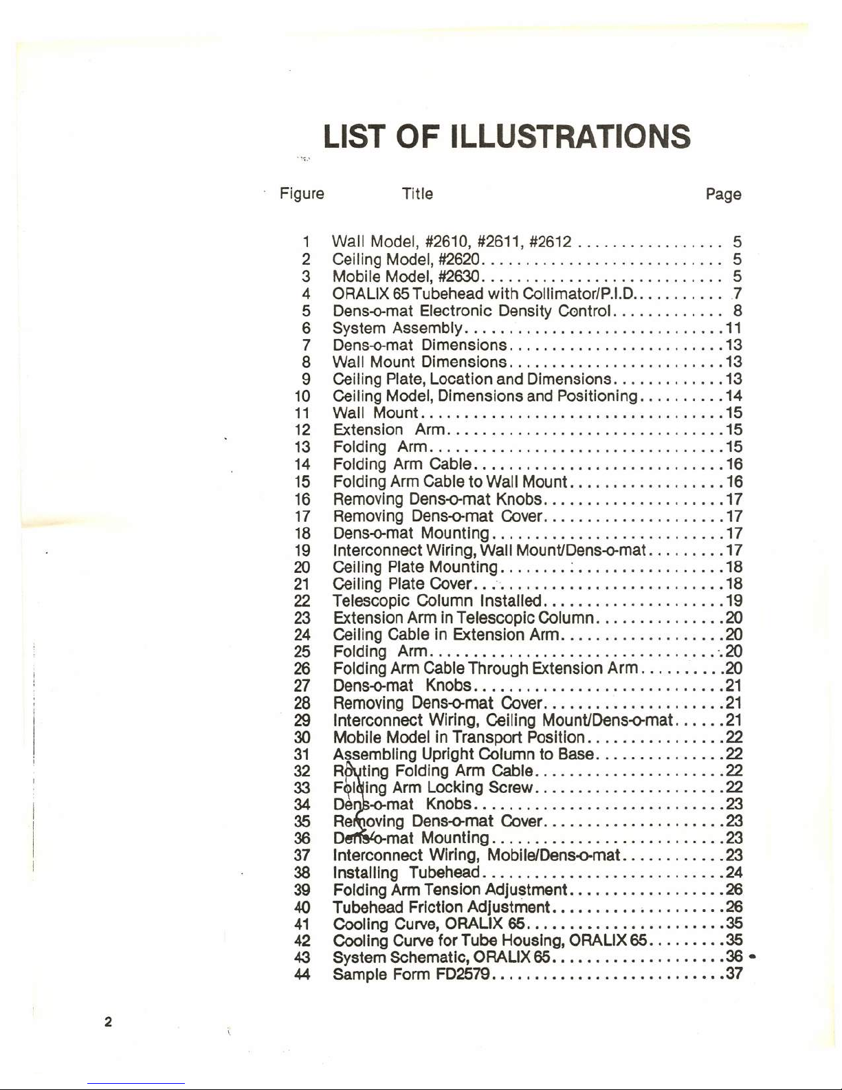
LIST OF ILLUSTRATIONS
Title
Page
Wall Model, #2610, #2611, #2612 5
Ceiling Model, #2620 5
Mobile Model, #2630. . . . . . . . . . . . . . . . . . . . . . . . . . .. 5
ORALIX 65 Tubehead with Collimator/P.I.D.. . . . . . . . .. .7
Dens-o-mat Electronic Density Control. . . . . . . . . . . .. 8
System Assembly 11
Dens-o-mat Dimensions 13
Wall Mount Dimensions 13
Ceiling Plate, Location and Dimensions 13
Ceiling Model, Dimensions and Positioning 14
Wall Mount 15
Extension Arm 15
Folding Arm 15
FOlding Arm Cable 16
FOlding Arm Cable to Wall Mount. 16
Removing Dens-o-mat Knobs 17
Removing Dens-o-mat Cover. 17
Dens-o-mat Mounting 17
Interconnect Wiring, Wall MountlDens-o-mat 17
Ceiling Plate Mounting ; 18
Ceiling Plate Cover 18
Telescopic Column Installed 19
Extension Arm in Telescopic Column 20
Ceiling Cable in Extension Arm 20
Folding Arm -.20
Folding Arm Cable Through Extension Arm 20
Dens-o-mat Knobs 21
Removing Dens-o-mat Cover 21
Interconnect Wiring, Ceiling MountiDens-o-mat 21
Mobile Model in Transport Position 22
Assembling Upright Column to Base 22
R ting Folding Arm Cable 22
Fling Arm Locking Screw 22
De -o-mat Knobs 23
Re oving Dens-o-mat Cover. 23
D mat Mounting 23
Interconnect Wiring, MobilelDens-o-mat 23
Installing Tubehead 24
Folding Arm Tension Adjustment 26
Tubehead Friction Adjustment ~ 26
Cooling Curve, ORALIX 65 35
Cooling Curve for Tube Housing, ORALIX 65 35
System SchematiC, ORALIX 65 36 •
Sample Form FD2579 37
Obligation of the Installer
1.Toinsure that the line voltage specified by the manufacturer of the
equipment is available, and line voltage regulation is within
specification.
2. To install and test the equipment and retain the recorded results
according to the installation instructions from the manufacturer and
with due regard to his training as a qualified serviceman.
3. Toprovide this Operator's Manual to the user.
4. To give the user, State and F.D.A.a copy of the FD.A. form "Report
of Assembly of a Diagnostic X-ray System" #FD2579, properly filled
out. This form should include the purchaser's name and address,
the installer or dealer's name and address, the identification, model
and serial number of all Certified items installed, and the signature
of the installer.
Obligation of the User
It is the responsibility of the user to maintain the equipment in
compliance by following the manufacturer's recommended main-
tenance schedule.
Failure of the user to properiy maintain the
equipment may relieve the manufacturer, or his agent, from
responsibility for any non-compliance personal injury or damage
which may resuH.
•
3

SECTION I
General Description
Introduction
This manual provides instructions for installing, operating and
maintaining the' Philips Oralix 65 Dental X-ray System (Series #2600)
models listed below.
Tab/e 1. Oralix 65 Denta/ X-ray System - Series #2600
Model No. Description
2610,2611,2612 Wall Model
2620 Ceiling Model
2630 Mobile Model
All models of the Oralix 65 Dental X-ray System include the
Oralix 65 Tubehead with 8" Collimator/P.I.D., Folding Arm and
Dens-e-mat
Electronic Density Control
A Wall Mount, Extension Arm, Ceiling Mount or Mobile Pedes-
tal is also supplied, depending on the model selected.
The Oralix 65 Dental X-ray System is designed for intraoral
dental radiography and is ideally suited for use with A. S.A. type
"0"
and "E" film.
WARNING
X-ray units produce ionizing radiation that may be harmful if
not properly controlled. It is therefore recommended that this equip-
ment be operated in accordance with the guidelines of the National
Council on Radiation Protection.
•
4
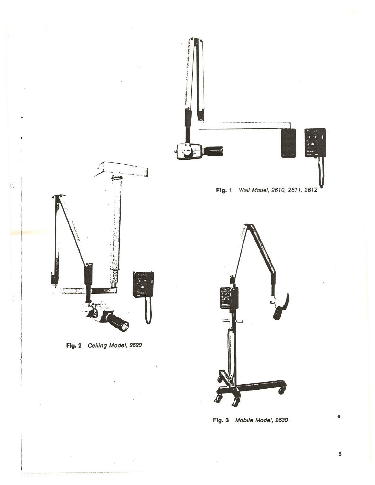
Fig. 2 Ceiling Model, 2620
Fig. 1 Wall Model. 2610. 2611. 2612
Fig. 3 Mobile Model, 2630
•
5

Table 2.
Oralix
65
Models and Components
Model Number
. and Description
Component and Catalog Number
Oralix 65 Tubehead · 9801 100 31304
8" Collimator/PJO. · 4519 100 28792
2610
Dens-e-mat
· 9801 710 80304
Wall Model Folding Arm · 9801 501 50104
2611,2612
Wall Mount ·9801 600 81004·
-
(see below)
* *
Extension Arm, 28"
· 9801 601 30104·
*Installation Kit
·9801 09390307·
Oralix 65 Tubehead
·9801 100 31304
8" Collimator/P.I.O.
· 4519 100 28792
2620 Oens-o-rnat
- 9801 71080304
Ceiling Model
FOlding Arm
- 9801 501 50104
Ceiling Mount · 9801 601 90004
Extension Arm, 20"
· 9801 601 20204
*Installation Kit
- 9801 09390307
Oralix 65 Tubehead - 9801 100 31304
8" Collimator/P.I.D.
·4519 100 28792
2630
Dens-o-mat
- 9801 71080304
Mobile Model FOlding Arm - 9801 501 50104
Mobile Pedestal
- 9801 50201204
*Installation Kit
·9801 09390307
Instruction Manual
* Installation Kit Sample and Blank Form F02579
9801 093 90307
Wire Nuts (4)
Line Plug
**
2611
Same as Model 2610 except Extension Arm
Wall Model
Extension Arm, 20" - 9801 601 20104
2612 Same as Model 2610 except Extension Arm
Wall Model
Extension Arm, 12" - 9801 601 10104
•
6
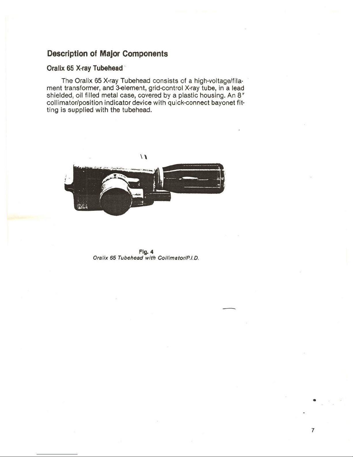
Description of Major Components
Oralix 65 X·ray Tubehead '
The Oralix 65 X"ray Tubehead consists of a high·voltage/fila·
ment transformer, and 3-element, grid-control X-ray tube, in a lead
shielded, oil filled metal case, covered by a plastic housing. An
8"
collimator/position indicator device with quick-connect bayonet fit·
ting is supplied with the tubehead.
Fig. 4
Oralix 65 Tubehead with Collimator/P.I.D.
•
7
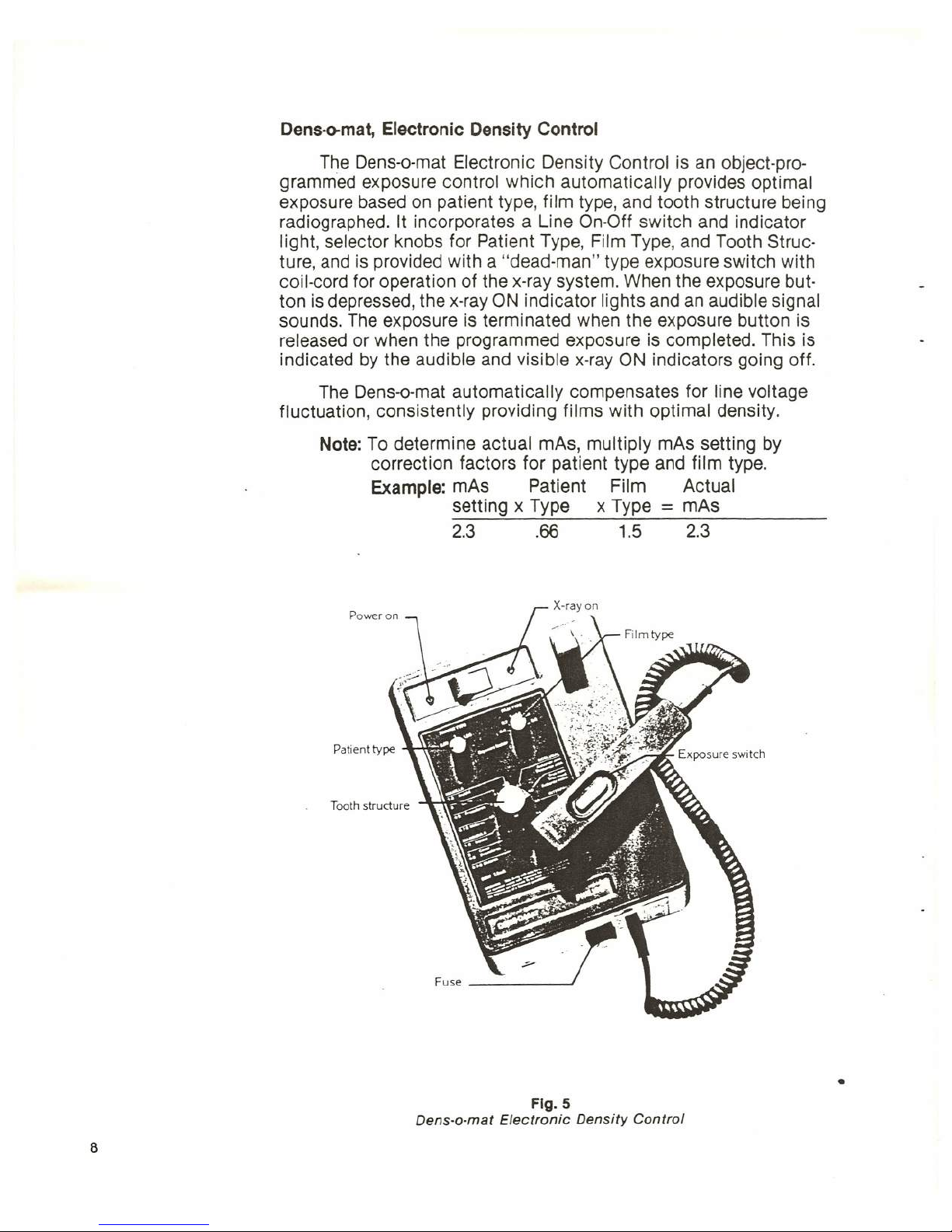
Dens-e-mat,
Electronic Density Control
The Dens-o-mat Electronic Density Control is an object-pro-
grammed exposure control which automatically provides optimal
exposure based on patient type, film type, and tooth structure being
radiographed. It incorporates a Line On-Off switch and indicator
light, selector knobs for Patient Type, Film Type, and Tooth Struc-
ture, and is provided with a "dead-man" type exposure switch with
coil-cord for operation of the x-ray system. When the exposure but-
ton is depressed, the x-ray ON indicator lights and an audible signal
sounds. The exposure is terminated when the exposure button is
released or when the programmed exposure is completed. This is
indicated by the audible and visible x-ray ON indicators going off.
The Dens-o-mat automatically compensates for line voltage
fluctuation, consistently providing films with optimal density.
Note:
To determine actual mAs, multiply mAs setting by
correction factors for patient type and film type.
Example:
mAs Patient Film Actual
setting x Type x Type
=
mAs
2.3 .66 1.5 2.3
Tooth structure
~.~,f
Fuse
-JI
•
Fig. 5
Dens-e-met Electronic Density Control
8

FOlding Ann
The FOlding Arm is a 2-section spring counter-balanced dental
x-ray arm. The end of the Folding Arm has a 3-conductor cable
which interconneCts with the Dens-a-mat Control via the Wall
Mount, Ceiling Mount or Mobile Pedestal, when the system is
assembled.
Extension Anns
A 28" Extension Arm* is provided with the Wall Model and a
20" Extension Arm is provided with the Ceiling Model. Electrical
wiring and mechanical interconnection between the FOlding Arm
and either the Wall Mount or Ceiling Mount is made via the Exten-
sion Arm. *For Model 2610. Models 2611, 2612 supplied with 20",
12" Extension Arm respectively.
Wall Mount
The Wall Mount incorporates a mechanical fitting into which
the support tube of the Extension Arm is installed. A terminal strip
is provided for wiring interconnection between the Dens-o-mat Elec-
tronic Density Control and the Folding Arm and Tubehead.
Ceiling Mount
The Ceiling Mount Assembly consists of a ceiling column with
mounting plate, telescopic column and cover. The ceiling column is
designed to be secured to a suitably reinforced ceiling with the
mounting plate provided. A terminal strip on the mounting plate is
provided for wiring interconnection between the Dens-o-mat Con-
trol and the Folding Arm and Tubehead.
Mobile Pedestal
The Mobile Pedestal incorporates a vertical upright column
which mounts on a weighted base with four casters. The upright
column terminates in a mechanical fitting into which the F91ding
Arm mounting is installed. Provision is made on the vertical upright
column for mounting the Dens-o-mat Control.
•
9
SECTION II
Information for the Assembler
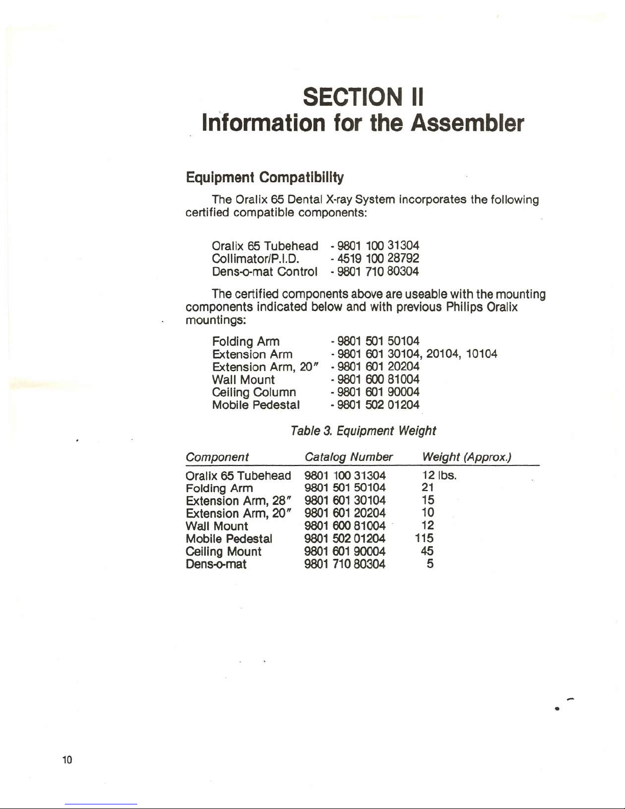
Equipment Compatibility
The Oralix 65 Dental X-ray System incorporates the following
certified compatible components:
Oralix 65 Tubehead - 9801 100 31304
Collimator/P.I.O. - 4519 100 28792
Dens-o-rnat Control - 9801 71080304
The certified components above are useable with the mounting
components indicated below and with previous Philips Oralix
mountings:
Folding Arm
Extension Arm
Extension Arm, 20"
Wall Mount
Ceiling Column
Mobile Pedestal
- 9801 501 50104
- 9801 601 30104, 20104, 10104
- 9801 601 20204
- 9801 600 81004
- 9801 601 90004
- 9801 502 01204
Table3.Equipment Weight
Component
Catalog Number
Weight (Approx.)
Oralix 65 Tubehead
Folding Arm
Extension Arm, 28"
Extension Arm, 20"
WaJl Mount
Mobile Pedestal
Ceiling Mount
Oens-o-mat
10
9801 100 31304
9801 501 50104
9801 601 30104
9801 601 20204
9801 600 81004 .
980150201204
9801 601 90004
9801 71080304
121bs.
21
15
10
12
115
45
5
•
 Loading...