

Philips 241P3ES/00, 241P3EB/00, 241P3EB/69, 241P3EB/27, 241P3EB/75 Service Manual
...
Description Page
Important Safety Notice--------------------------------------2
Technical Data--------------------------------------------- -3~4
Installation-------------------------------------------------------5
On Screen Display------------------------------------------8~9
Lock/unlock, Aging,Factory mode-------------------------10
---------------------------------11
Mechanical Instructions ------------------------------12~15
Color adjustment --------------------------------------------16
Electrical instruction ----------------------------------19~20
DDC Instructions & Serial Number -----------------23~29
DDC DA T A -----------------------------------------------30~31
------------------------32~33
Philips Pixel Defect Policy
FAQs (Frequently Asked Questions)---------------17~18
Firmware Upgrade for CPU-
Horizontal frequencies
30-83kHz
TABLE OF CONTENTS
Description Page
-----------------------------------34
Wiring Diagram----------------------------------------------35
Block Diagram------------------------------------------------36
Power
Control Diagram & C.B.A. -----------------------------44~45
Failure Mode Of Panel -
SAFETY NOTICE
Chassis:
24
REFERTO BACK COVER FOR
IMPORTANT SAFETY GUIDELINES
ANY PERSON
ATTEMPTING TOSERVICE THIS CHASSIS
MUST FAMILIARIZE
HIMSELF
WITH THE
CHASSIS
AND BE A W ARE OF THE NECESSAR Y SAFETY PRECAUTIONS
TO BE USED WHEN
SERVICING ELECTRONIC
EQUIPMENT CONTAINING
HIGH VOLTAGES.
CAUTION:
USE
A SEPARATE
ISOLATION TRANSFORMER FOR THIS UNIT WHEN SERVICING.
Published by Philips Consumer Lifestyle Copyright reserved Subject to modification JJan 11 2011
Scaler Diagram & C.B.A. ------------------------------37~40
GB
MERIDIAN 3
Troubleshooting---------------------------------------------6~7
Service Tool-----------------------------------------------21~22
241P3ES/00
inch FHD
General product specification------------------------51~83
Exploded V iew -----------------------------------------------84
Spare/ arts List-------------------------85
Recommended P
PCBA photos---------------------------------------------------86
Repair tips-------------------------------------------------87~88
Repair Flow chart----------------------------------------89~90
Safety Test Requirments------------------------------------91
LCD Colour Monitor
TFT
Diagram & C.B.A.
------------------------------41~43
USB
Diagram & C.B.A.--------- -------------------------46~50
241P3EB/00
241P3EB/69
241P3EB/27
241P3EB/75
241P3EB/93
Important Safety Notice
Proper service
operation of all Philips Consumer Electronics Co
mpany
equipment. The service procedures
re
commended by
Phil
ips and
described in this service manual a
re eff
ect
ive met hod
sof
performing service ope
rations
.Someof
these s ervic
e
operations require the useof tools speciall y desi gned
for the
purpose. The spe
cial tools should be used w
hen and as
recomm ended.
It is im portant to note t hat this m anual c ontains various
CAUTI ON
S and NOTICES which should be
carefully read in
order to m inimize the risk of personal injury to servic
e
personnel . T he possibility exists th
at im
proper
servi
ce
methods may damage the equipment
. It is also important t
o
underst and that these CAUTIONS and NOTICES ARE NOT
EXHAU STIVE. Phil
ips
could not possibly know, evaluate and
advise the servic etrade of all concei vable ways i n w
hic
h
service might be done or of the possible hazardous
consequences of each way. Consequently,Philips has not
undertaken any suc
h broad evalua
ti
on. Accordingly
,
who uses a servi ce procedure or tool which is not
recommended by Philipsmust f
irst sati
sfy
himself thoroughly that
neither his saf ety nor the safeoperation of the equipment will
be jeopardized by the servi
ce method sel
ect ed.
* * Hereaf ter throughout this manu
al,
PhilipsConsumer
Electronics Co mpany w
ill
be referred to as Philip
s
.
**
Critical components havingspecial safety characteristics are
identified w ith a by the Ref. No. in the parts list and
enclosed within a broken line
(where several critic al co
mponents are grouped in
one area)
along with t he saf e
ty s
y
mbol on the schematics
or
exploded vie
ws.
Use of s
ub
stitute replacement parts w hich do no
t have the
same specified safety charact eristics may create
shock,
fire,
or other hazards .
Under no cir cums tances s hould th
e original
design be
modified or altered without written permission from Philip
s.
Philips assumes no liabilit
y, express or implied, arising
out of
any unauthorized modification of design.
Servicer assumes all liability.
WARNING
Take care during handling the LCD module with backlight
unit
- Must mount the module using mounting holes arranged in four
corners.
- Do not press on the panel, edge of the frame strongly or electric
shock as this will result in damage to the screen.
- Do not scratch or press on the panel with any sharp objects, such
as pencil or pen as this may result in damage to the panel.
- Protect the module from the ESD as it may damage the electronic
circuit (C -MOS).
-
Make certain that treatment body are grounded through
wrist band.
- Do not leave the
module in high temperature and
in areas of high
humidity for a long time.
- Avoid contact with water as it may as hort circuit within the module.
-
If the surface of panel become dirty
, please wi
pe it of f with a soft
material. (Cleaning with a dirty or rough cloth may damage the
panel.)
FOR PRODUCTS CONTAINING LASER :
DANGER - Invisible laser radiation when open.
AVOID DIRECT EXPOSURE T
O BEAM.
CAUTION - Use of controls or adjustments or
performance of procedures other than
those specified herein may result
in
hazardous radiation exposure.
CAUTION - The use of optical instruments with this
product will increase eye hazard.
TO ENSURE THE CONTINUED RELIABILITY
OF THIS
PRODUCT, USE ONLYORIGINAL
MANUF
ACTURER'S
REPLACEMENT PARTS, WHICH ARE LISTED WITH THEIR P
ART
NUMBERS IN THE PAR
TS LIST SECTION OF
THIS
SERVICE MANUAL.
and repair is important
to the sa
fe,
reliable
2 241P3 LCD
241P3 LCD 3
Technical Data
AUO
Type NR.
: AUO M240HW01 V2
Resolution
: 1920 x 1080 (FHD)
Outside dimensions
: 556.0(H) x 323.2(V) x 16.35(D)
mm
Pitch (mm) : 0.276mm x 0.276mm
Color pixel
arrangement
: 1920 horiz. by 1080 vert. Pixels.
RGB stripe arrangement
Display surface
: Hard coating (3H), Anti-glare
treatment
Color depth : 16.7 M colors 8-bit with A-FRC
Backlight : CCFL
Active area (W x H)
: 531.36mm (H) ×298.89mm (V)
mm
View angle (CR=10) : >=170 for Right/Left (Typ)
: >=160 for Up/Down (Typ)
Contrast ratio : >=1000:1 (Typ)
White luminance : 300 (center,Typ)
Color gamut : 70%
Gate IC :
Source IC :
Response time : 5 ms (Typ)
Vertical frequency
range
: 47~75 H z
Scanning frequencies
Hor.: 30 – 83 K Hz
Ver.: 56 - 76 Hz
Video dot rate: < 205 MHz for VGA and < 165 MHz for DVI
Power input: 90-264 V AC, 50/60 r 2 Hz
Power consumption: Normal on: < 52 W (max)
Functions:
(1) D-SUB analog R/G/B separate inputs, H/V sync
separated, Composite (H+V) TTL level, SOG sync.
(2) DVI digital Panel Link TMDS inputs, HDCP supported.
Ambient temperature: 0
q
C - 40 qC
Power input connection
Power cord length : 1.8 M
Power cord type : 3 leads po wer cord with protective earth plug.
Power management
Mode HS
YN
C
VSYNCVideo Pwr-cons.IndicationRec.
time
Power-On On On Active
<42W
(typ.)
<
52W(max.
)
White LED
--
Standby Off Off Blanked < 0.2W
Blinking
white LED
3 sec on
3sec off
<3s
DC Power
Off
ʳʳ N/A < 0.2 W LED Off ʳ
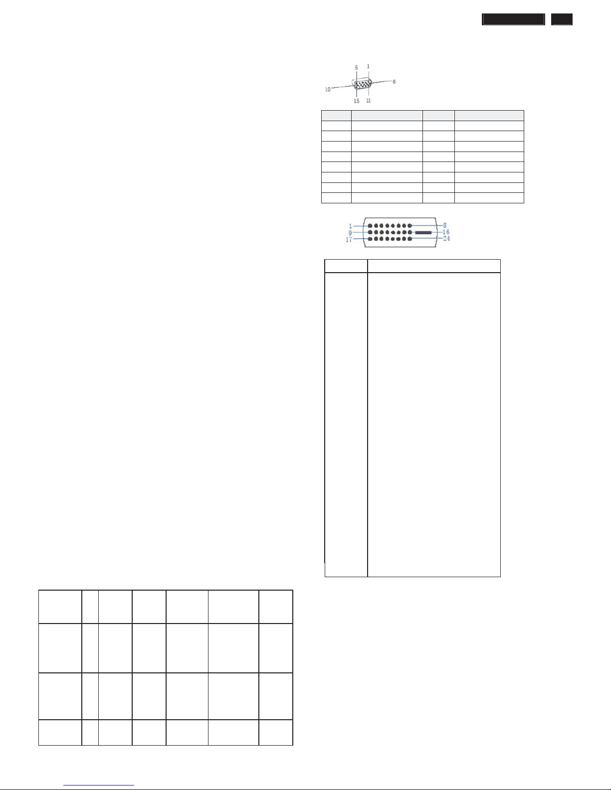
PIN No. SIGNAL PIN No. SIGNAL
1 Red 9 DDC +3.3V or +5V
2 Green/ SOG 10 Logic GND
3 Blue 11 Sense (GND)
4 Sense (GND) 12 Bi-directional data
5 Cable Detect (GND) 13 H/H+V sync
6 Red GND 14 V-sync
7 Green GND 15 Data clock
8 Blue GND
ʳʳ
Susceptibility of display to external environment
Operating
- Temperature : 0 to 40 degree C
- Humidity :80% max
- Altitude :0-3658m
- Air pressure : 600-1100 mBAR
Storage
- Temperature : -20 to 60 degree C
- Humidity : 95% max
- Altitude : 0-12192m
- Air pressure : 300-1100 mBAR
Note: recommend at 5 to 35qC, Humidity less than 60 %
Pin No. Description
1 T.M.D.S. data22 T.M.D.S. data2+
3 T.M.D.S. data2 shield
4 No Connect
5 No Connect
6 DDC clock
7 DDC data
8 No Connect
9 T.M.D.S. data110 T.M.D.S. data1+
11 T.M.D.S. data1 shield
12 No Connect
13 No Connect
14 +5V Power
15 Ground (for +5V)
16 Hot plug detect
17 T.M.D.S. data018 T.M.D.S. data0+
19 T.M.D.S. data0 shield
20 No Connect
21 No Connect
22 T.M.D.S clock shield
23 T.M.D.S. clock+
24 T.M.D.S. clock-
4 241P3 LCD
Technical Data
QISDA
Type NR.
: QISDA LCD M240QW01 V0
Resolution
: 1920 x 1080 (FHD)
Outside dimensions
: 556.0(H) x 323.2(V) x 16.35(D)
mm
Pitch (mm) : 0.276mm x 0.276mm
Color pixel
arrangement
: 1920 horiz. by 1080 vert. Pixels.
RGB stripe arrangement
Display surface
: Hard coating (3H), Anti-glare
treatment
Color depth : 16.7 M colors 8-bit with A-FRC
Backlight : CCFL
Active area (W x H)
: 531.36mm (H) ×298.89mm (V)
mm
View angle (CR=10) : >=170 for Right/Left (Typ)
: >=160 for Up/Down (Typ)
Contrast ratio : >=1000:1 (Typ)
White luminance : 300 (center,Typ)
Color gamut : 70%
Gate IC :
Source IC :
Response time : 5 ms (Typ)
Vertical frequency
range
: 47~75 H z
Scanning frequencies
Hor.: 30 – 83 K Hz
Ver.: 56 - 76 Hz
Video dot rate: < 205 MHz for VGA and < 165 MHz for DVI
Power input: 90-264 V AC, 50/60 r 2 Hz
Power consumption: Normal on: < 52 W (max)
Functions:
(1) D-SUB analog R/G/B separate inputs, H/V sync
separated, Composite (H+V) TTL level, SOG sync.
(2) DVI digital Panel Link TMDS inputs, HDCP supported.
Ambient temperature: 0
q
C - 40 qC
Power input connection
Power cord length : 1.8 M
Power cord type : 3 leads po wer cord with protective earth plug.
Power management
Mode HS
YN
C
VSYNCVideo Pwr-cons.IndicationRec.
time
Power-On On On Active
<42W
(typ.)
<
52W(max.
)
White LED
--
Standby Off Off Blanked < 0.2W
Blinking
white LED
3 sec on
3sec off
<3s
DC Power
Off
ʳʳ N/A < 0.2 W LED Off ʳ
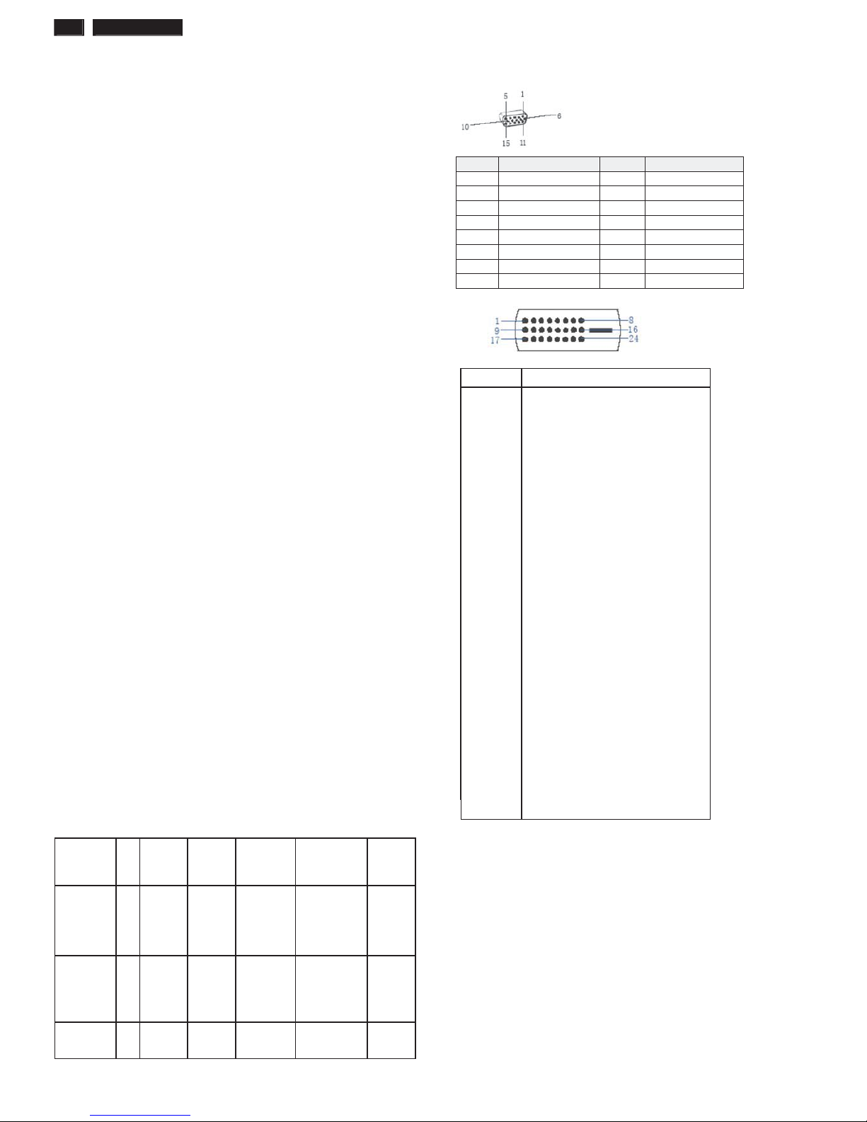
PIN No. SIGNAL PIN No. SIGNAL
1 Red 9 DDC +3.3V or +5V
2 Green/ SOG 10 Logic GND
3 Blue 11 Sense (GND)
4 Sense (GND) 12 Bi-directional data
5 Cable Detect (GND) 13 H/H+V sync
6 Red GND 14 V-sync
7 Green GND 15 Data clock
8 Blue GND
ʳʳ
Susceptibility of display to external environment
Operating
- Temperature : 0 to 40 degree C
- Humidity :80% max
- Altitude :0-3658m
- Air pressure : 600-1100 mBAR
Storage
- Temperature : -20 to 60 degree C
- Humidity : 95% max
- Altitude : 0-12192m
- Air pressure : 300-1100 mBAR
Note: recommend at 5 to 35qC, Humidity less than 60 %
Pin No. Description
1 T.M.D.S. data22 T.M.D.S. data2+
3 T.M.D.S. data2 shield
4 No Connect
5 No Connect
6 DDC clock
7 DDC data
8 No Connect
9 T.M.D.S. data110 T.M.D.S. data1+
11 T.M.D.S. data1 shield
12 No Connect
13 No Connect
14 +5V Power
15 Ground (for +5V)
16 Hot plug detect
17 T.M.D.S. data018 T.M.D.S. data0+
19 T.M.D.S. data0 shield
20 No Connect
21 No Connect
22 T.M.D.S clock shield
23 T.M.D.S. clock+
24 T.M.D.S. clock-
241P3 LCD 5
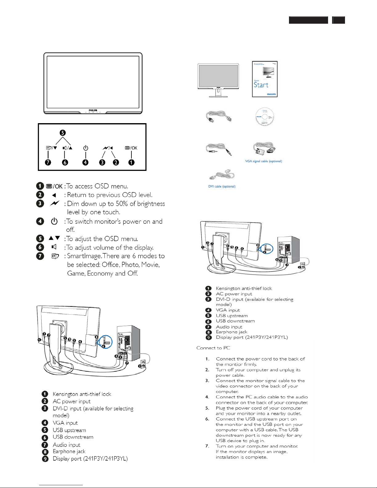
Installation
Front View Product Description
Rear View
ʳ
Accessory Pack
Unpack all the parts
Connecting to Your PC
1) Connect the power cord to the back of the monitor firmly.
(Philips has pre-connected VGA cable for the first installation.
6 241P3 LCD
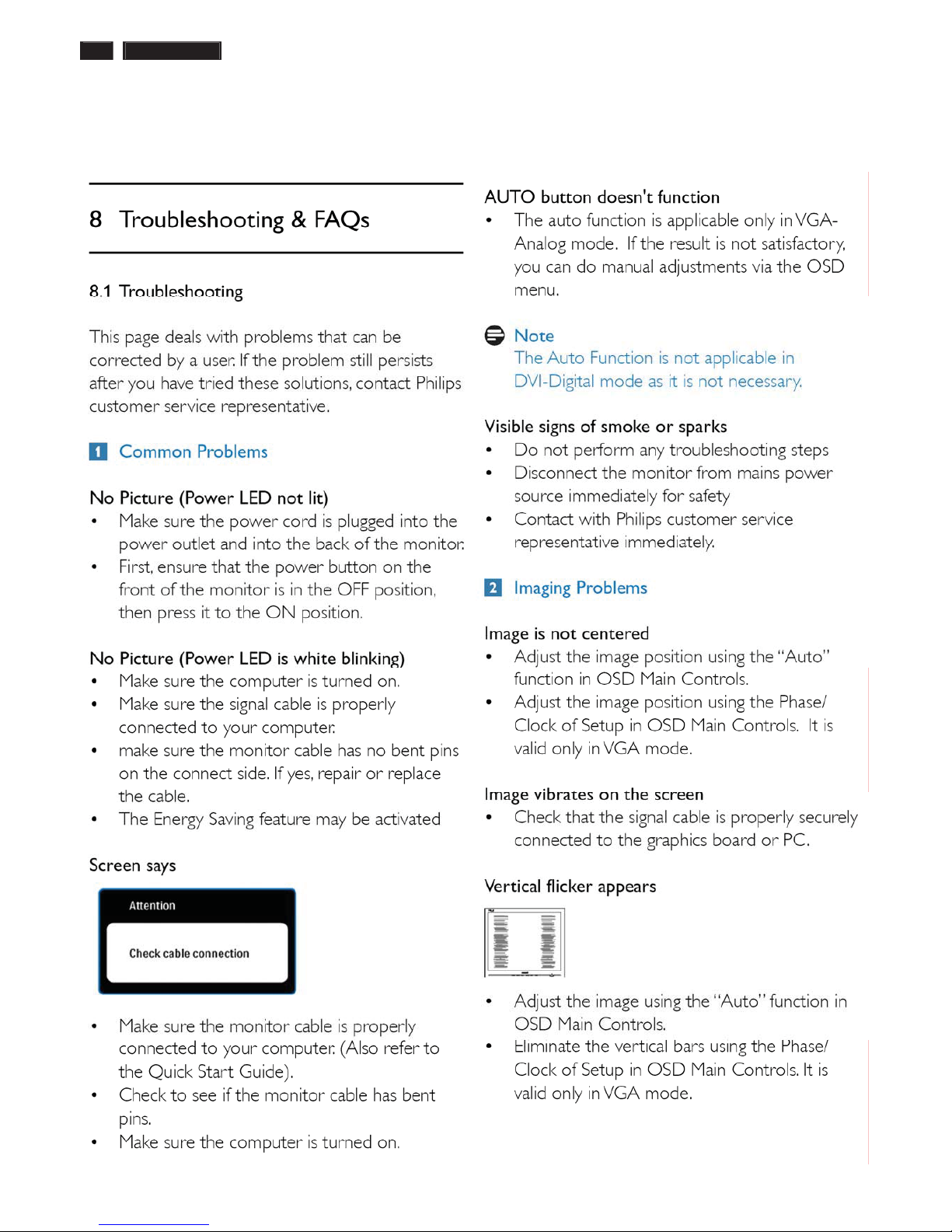
Troubleshooting
ʳ
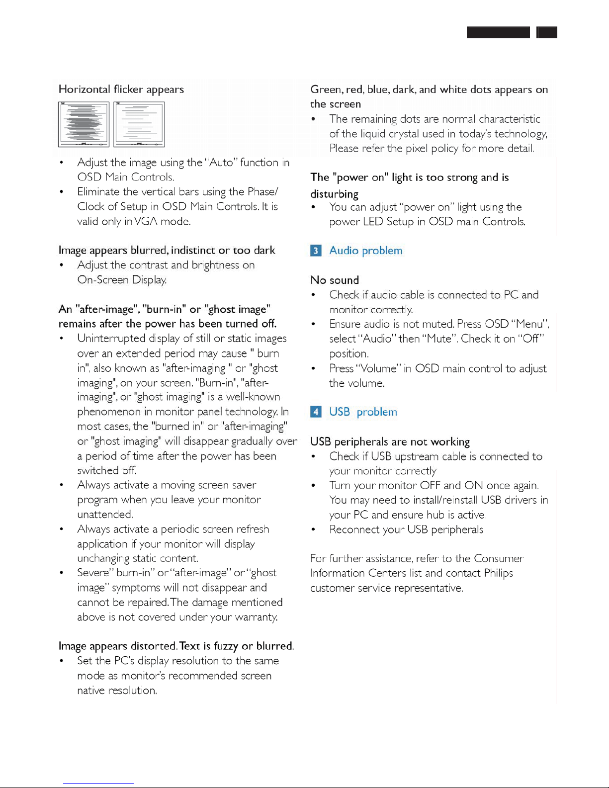
241P3 LCD 7
Troubleshooting
8 241P3 LCD
On-Screen Display
Description of the On Screen Display
ʳ
What is the On-Screen Display?
ʳ
On-Screen Display (OSD) is a feature in all Philips LCD monitors. It allows an end user to adjust screen performance or
select functions of the monitors directly through an on-screen instruction window. A user friendly on screen display
interface is shown as below :
ʳ
ʳ
Basic and simple instruction on the control keys.
ʳ
In the OSD shown above users can press buttons at the front bezel of the monitor to move the cursor, to
confirm the choice or change.
ʳ
ʳʳ
241P3 LCD 9
On-Screen Display
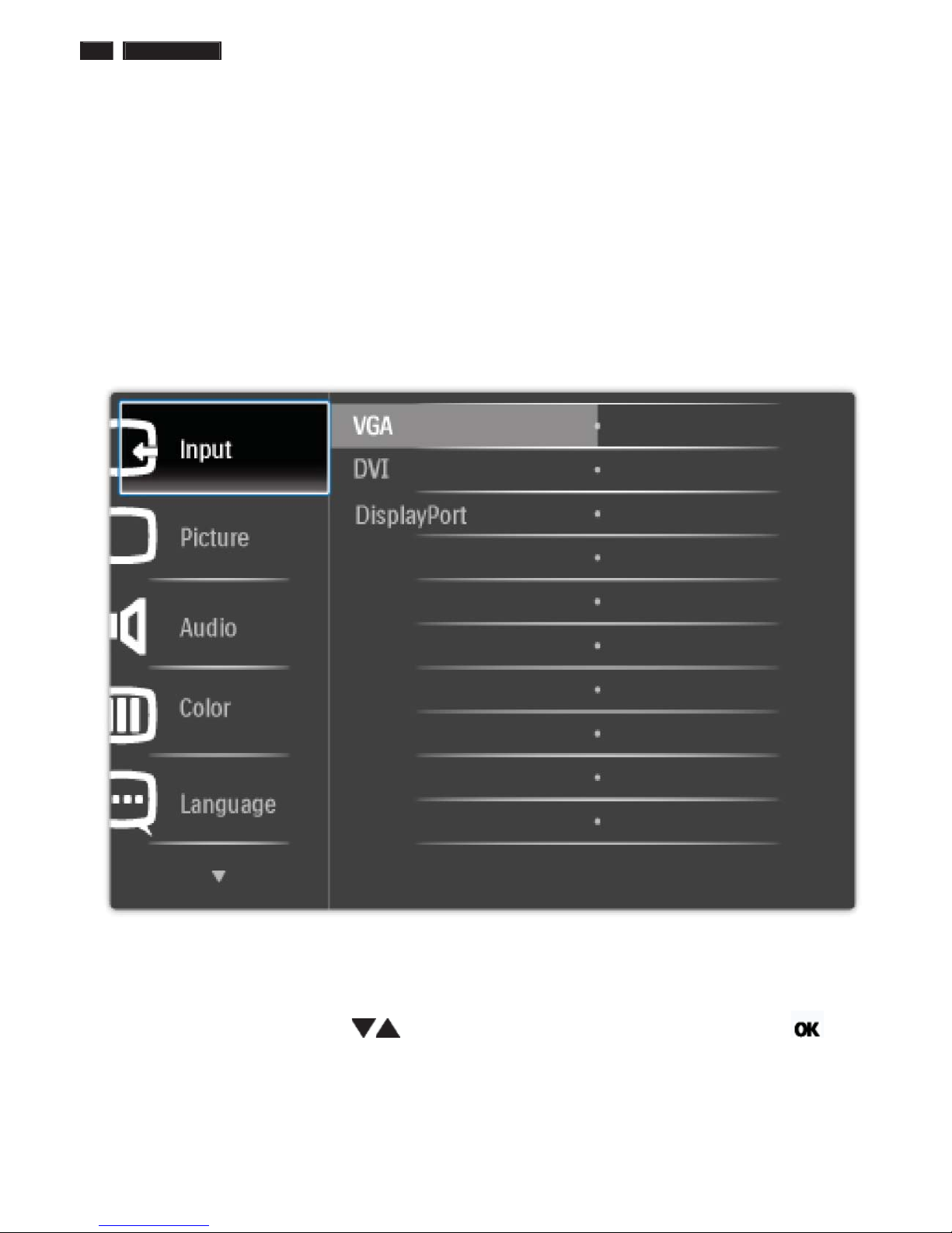
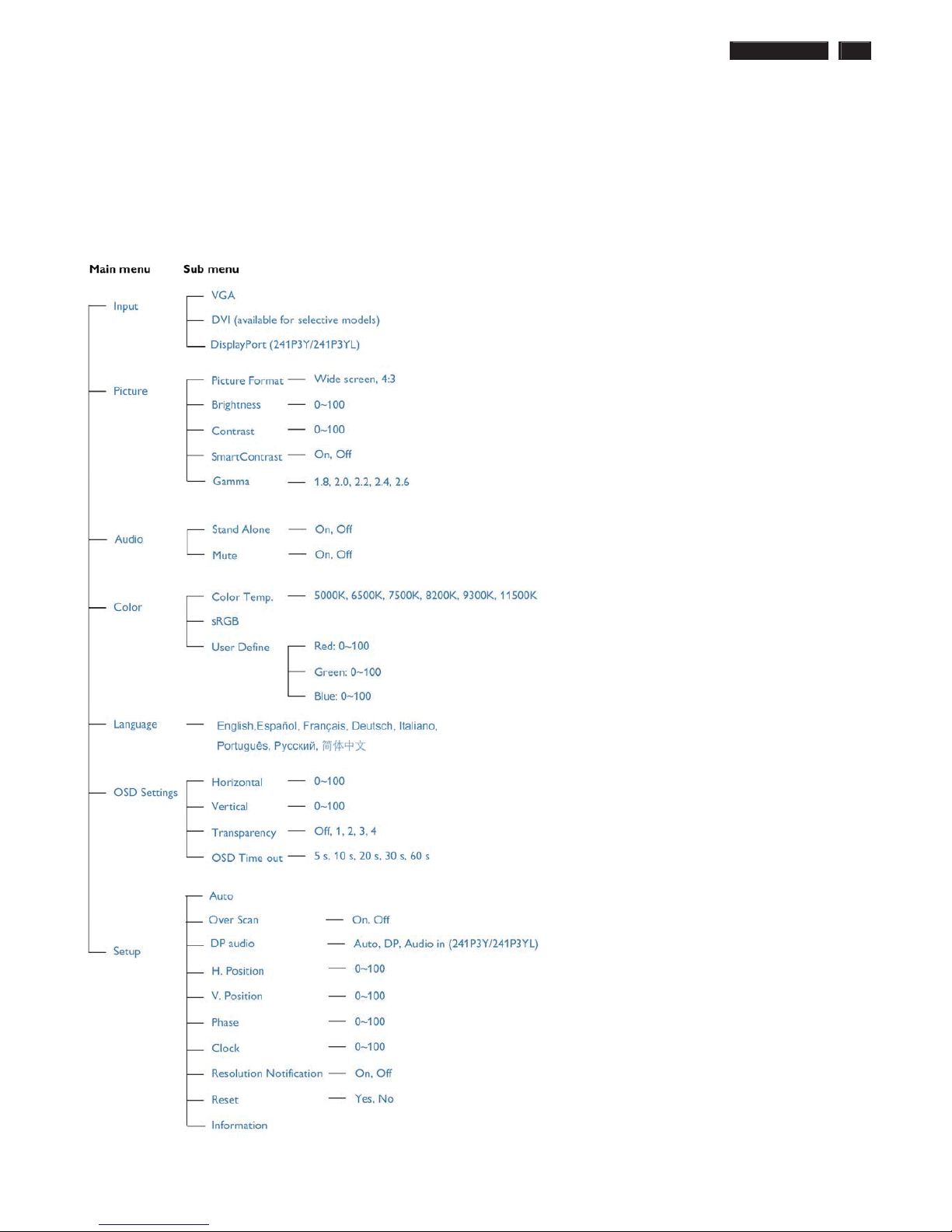
The OSD Tree
ʳ
Below is an overall view of the structure of the On-Screen Display. You can use this as a reference when you want to work
your way around the different adjustments later on.
ʳ
ʳ
10 241P3 LCD
/RFN8QORFN$JLQJ)DFWRU\0RGH
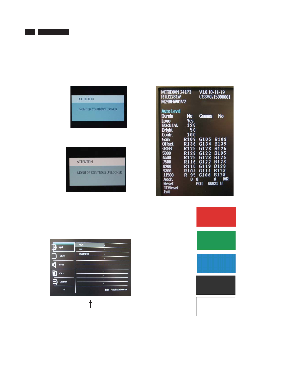
To lock/unlock OSD FUNCTION(User Mode)
The OSD function can be locked by pressing"OK"button(1) for more than 10
seconds, the screen shows following windows for 4 seconds. Every time
when you press"OK" button, this message appears on the screen
automatically .
Unlock OSD function
Unlocked OSD function can be released by pressing "OK" button for more
than 10 seconds again.
$FFHVV)DFWRU\0RGH
1). Turn off monitor.
2).[Push "EXIT" & "MENU" buttons at the same time and hold them]+[Press
"power" button until comes out "Windows screen" ]=> then release all
buttons
3).Press "MENU" button, wait until the OSD menu with Characters
"MERIDIAN 241P3 V1.0 2010-11-19” (below OSD menu) come on the
Screen of the monitor.
Factory Mode indicator
Factory Menu
Cursor can move on gray color area
Hot key function: by pressing " UP " and " DOWN " key Simultaneously at
User Mode (or Factory Mode) (PS: The Of fset R G B function can be used
on reduce or eliminate snowy noise on the background when the resolution
of video signal is 1680*1050vertical 60Hz. Slightly increase or decrease the
value until snowy noise completely disappear .
$FFHVV$JLQJ0RGH
Step 1 : Access Factory Mode then enter Factory Menu.
Step 2 : By pressing " UP" and " DOWN " key to Burning Icon. Press
"MENU then press " UP" and "DOWN " key to turn on Aging Mode.
Step 3 : Disconnect interface cable between Monitor and PC.
After 3 seconds,
bring up:
repeatly
Connect Signal cable again=> go back to normal display

241P3 LCD 11
Philips Pixel Defect Policy
ʳ
Philips' Flat Panel Monitors Pixel Defect Policy
ʳ
Philips strives to deliver the highest quality products. We use some of the
industry's most advanced manufacturing processes and practice stringent
quality control. However, pixel or sub pixel defects on the TFT LCD panels
used in flat panel monitors are sometimes unavoidable. No manufacturer
can guarantee that all panels will be free from pixel defects, but Philips
guarantees that any monitor with an unacceptable number of defects will be
repaired or replaced under warranty. This notice explains the different types
of pixel defects and defines acceptable defect levels for each type. In order
to qualify for repair or replacement under warranty, the number of pixel
defects on a TFT LCD panel must exceed these acceptable levels. For
example, no more than 0.0004% of the sub pixels on a 19" XGA monitor may
be defective. Furthermore, Philips sets even higher quality standards for
certain types or combinations of pixel defects that are more noticeable than
others. This policy is valid worldwide.
Pixels and Sub pixels
A pixel, or picture element, is composed of three sub pixels in the primary
colors of red, green and blue. Many pixels together form an image. When all
sub pixels of a pixel are lit, the three colored sub pixels together appear as a
single white pixel. When all are dark, the three colored sub pixels together
appear as a single black pixel. Other combinations of lit and dark sub pixels
appear as single pixels of other colors.
ʳTypes of Pixel Defects
ʳ
Pixel and sub pixel defects appear on the screen in different ways. There are
two categories of pixel defects and several types of sub pixel defects within
each category. ʳ
Bright Dot Defects Bright dot defects appear as pixels or sub pixels that are
always lit or 'on'. That is, a bright dot is a sub-pixel that stands out on the
screen when the monitor displays a dark pattern. There are the types of
bright dot defects:ʳ
ʳ
ʳ
One lit red, green or
blue sub pixelʳ
Two adjacent lit sub
pixels:
- Red + Blue =
Purple
- Red + Green =
Yellow
- Green + Blue =
Cyan (Light Blue)!
Three adjacent lit sub
pixels (one white
pixel)ʳ
ʳ
A red or blue bright dot must be more than 50 percent brighter
than neighboring dots while a green bright dot is 30 percent
brighter than neighboring dots.ʳ
Black Dot Defects Black dot defects appear as pixels or sub pixels that are
always dark or 'off'. That is, a dark dot is a sub-pixel that stands out on the
screen when the monitor displays a light pattern. These are the types of
black dot defects:ʳ
ʳ
One dark sub pixelʳ Two or three adjacent dark sub pixelsʳ
Proximity of Pixel Defects
ʳ
Because pixel and sub pixels defects of the same type that are near to one
another may be more noticeable, Philips also specifies tolerances for the
proximity of pixel defects.
Pixel Defect Tolerances
ʳ
In order to qualify for repair or replacement due to pixel defects during the
warranty period, a TFT LCD panel in a Philips flat panel monitor must have
pixel or sub pixel defects exceeding the tolerances listed in the following
tables.ʳ
BRIGHT DOT DEFECTSʳ
ACCEPTABLE
LEVEL ʳ
MODELʳ
241P3ʳ
1 lit subpixelʳ 3ʳ
2 adjacent lit subpixelsʳ 1ʳ
3 adjacent lit subpixels (one white pixel)ʳ 0ʳ
Distance between two bright dot defects*ʳ >15mmʳ
Total bright dot defects of all typesʳ 3ʳ
BLACK DOT DEFECTSʳ
ACCEPTABLE
LEVEL ʳ
MODELʳ
241P3
ʳ
1 dark subpixelʳ 5 or fewerʳ
2 adjacent dark subpixelsʳ 2 or fewerʳ
3 adjacent dark subpixelsʳ 0 ʳ
Distance between two black dot defects*ʳ >15mmʳ
Total black dot defects of all typesʳ 5 or fewerʳ
TOTAL DOT DEFECTSʳ
ACCEPTABLE
LEVEL ʳ
MODELʳ
241P3
ʳ
Total bright or black dot defects of all
typesʳ
5 or fewerʳ
Note:
* 1 or 2 adjacent sub pixel defects = 1 dot defect
12 241P3 LCD
Mechanical Instruction
Preparation before disassemble
1.Clean the room for disassemble
2.Identify the area for monitor
3.Check the position that the monitors be placed and the quantity of the monitor ;prepare the area for material flow;
according to the actual condition plan the disassemble layout
4.Prepare the implement, equipments, materials as be llow:
1) Press-fixture
2) working table
3) Screw-driver
4) knife*1
5) glove
6) cleaning cloth
7) ESD protection
ite
m
picture Operation Tool Notes
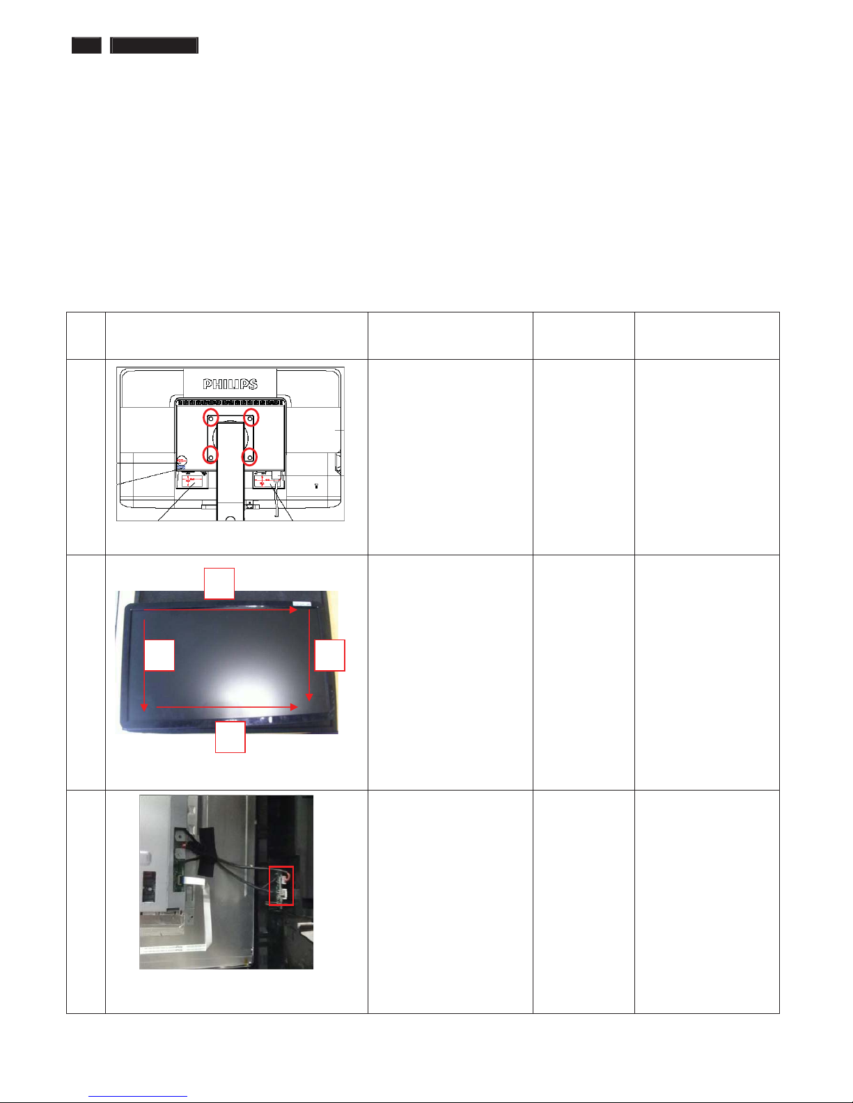
1 Tear off four piece of
Mylar
Disassemble the stand
Æ 4 screws
Screw-driver
2 Disassembly the bezel
from the monitor, notice
the disassembly order :
1.Top (1) parts of bezel
2.Left (2) parts of bezel
3.Bottom (3) parts of
bezel
4. Right (4) parts of bezel
Don’t draw the BZL
When disassembly
the bezel ,notice don’t
bend the C/B .man
must wear glove
The purpose is loose
the BZL
3 Turn over the
monitor ,Uplift the Rear
cover from the monitor
Tear off the acetic tape on
USB board
Draw the USB board
cable out USB board
Don’t dismantle the
Rear cover
1
2
3
4
241P3 LCD 13
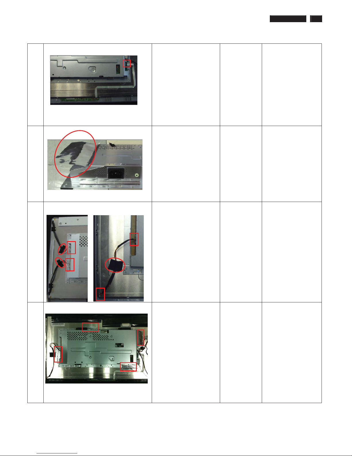
Mechanical Instruction
4 Draw the cable of contral
board
Take the entire internal
mechanism from Bezel
and put it on the cushion
5 Take off the aluminum
foils on the left of monitor
6
For 241P3Κ For 241P3LΚ
Tear off the acetic tape on
panel
Pull out lamps cable
7 Take off four pieces of
aluminum foils
14 241P3 LCD
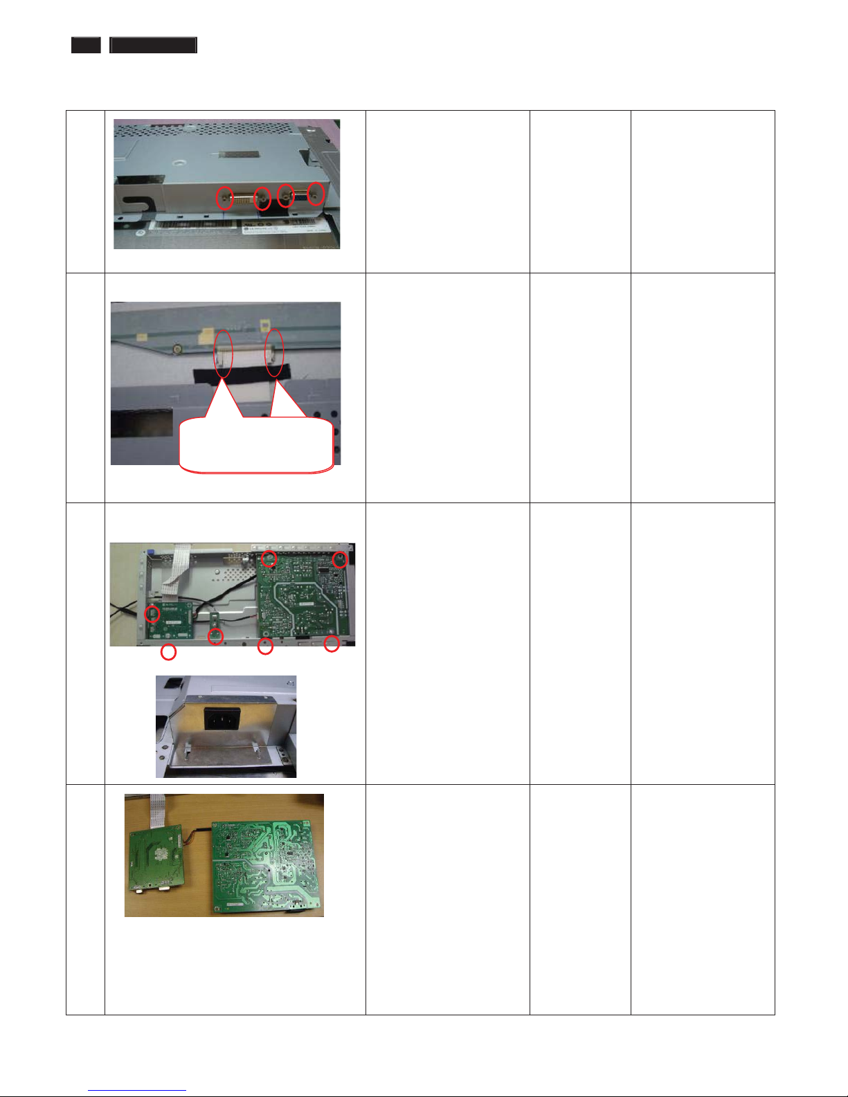
Mechanical Instruction
8 Disassembled the
Main-BKT : hexagonal
screw *4
Screw-driver
9 Tear off the acetic tape on
LVDS
Unlock the L V DS by using
two hands (see note).
Please carefully use
two hands (one hand
presses the
locking-latch of LV DS
cable’s housing, and
at the same time
another hand pulls out
the L V DS cable.) for
this step to avoid from
deforming the
terminals of
positive-locking type
LV DS cable.
10 Tear off the iron sheet
which cover the
AC-SOCKET
Disassemble the Power
boardΕUSB boardΕ
ITF-board
Æ 7 screws
Plus driver
1 1 Take the PCBA from
Main-BKT and then put
it on the cushion
The locking-latch
of LVDS cable’s
The locking-latch
of FFC cable’s
241P3 LCD 15
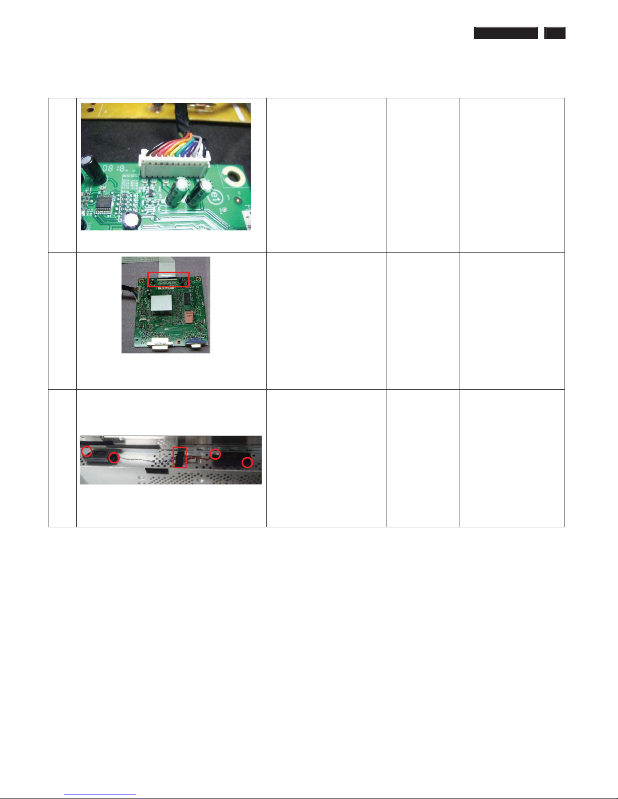
Mechanical Instruction
12 Pull out the cable of
Power boardΕthe cable of
USB board
Notes: Pull the
connect upright
13 Pull out the LVDS cable Notes: use one finger
lift up the cover of
connect ,and then pull
the LV DS cable
upright
14 Tear off the acetic tape on
SHD
Pull out the speaker
16 241P3 LCD
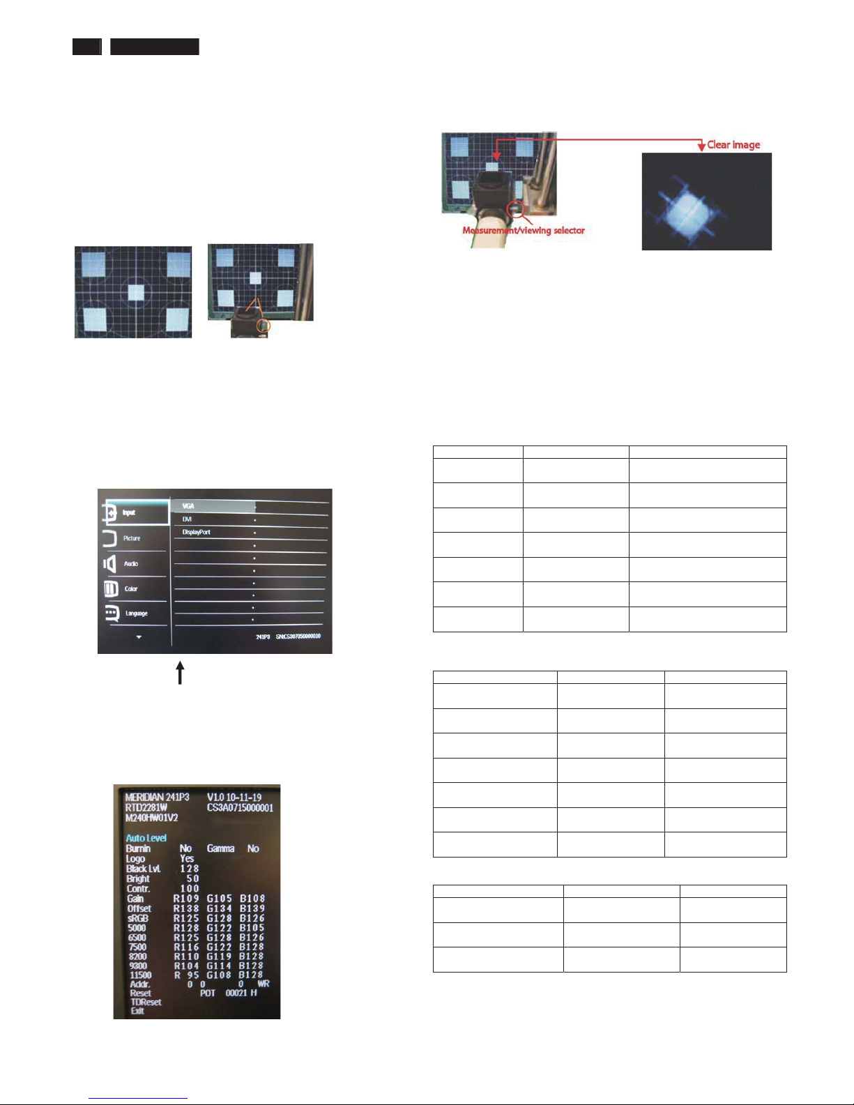
Color Adjustment
Alignment procedure
1. Turn on the LCD monitor
2. Turn on the Timing/pattern generator. See Fig.1
3. Preset LCD color Analyzer CA-1 10
-Remove the lens protective cover of probe CA-A30.
-Set measuring/viewing selector to measuring position for reset
analyzer .(zero calibration) as Fig.2
- Turn on the color analyzer (CA-1 10)
-Press 0-CAL button to starting reset analyzer .
Fig. 1 Fig.2
4. Access Factory Mode
1). Turn off monitor.
2). [Push "AUT O" & "MENU" buttons at the same time and hold them]
+[Press "power" button untill comes out "Windows screen" ]
=> then release all buttons
3).Press "MENU button, wait until the OSD menu with
Characters " MERIDIAN 241P3 V1.0 2010-11-19” (below OSD menu)
come on the Screen of the monitor as shown in Fig3.
Factory Mode indicator
)LJ
4). Press button, then select factory mode indicator by "MENU" "LEFT"
or "RIGHT" button .Press"MENU" button to bring up submenu
windows as below:
)LJ
Fig.5
5.Display
Press "UP" or "DOWN" button to select . Change the value
by "UP" or "DOWN" key until the X, Y co-ordinates as below
5.1 Color temperature adjustment
There are six factory preset white color 11500K, 9300K, 8200K, 7500K,
6500K, sRGB, 5000K
Align by Philips PerfecTune (also called FGA) function.
Apply full white pattern, with brightness in 100 % position and the contrast
control at 50 % position.
The 1931 CIE Chromaticity (color triangle) diagram (x , y) coordinate for
the screen center should be:
Product specification
CIE coordinates (x,y)
11500K x = 0.270 ± 0.02
y = 0.281 ± 0.02
PerfectuneII
9300K x = 0.283 ± 0.02
y = 0.297 ± 0.02
PerfectuneII
8200K x = 0.291 ± 0.02
y = 0.306 ± 0.02
PerfectuneII
7500K x = 0.298 ± 0.02
y = 0.314 ± 0.02
PerfectuneII
6500K/sRGB x = 0.313 ± 0.02
y = 0.329 ± 0.02
PerfectuneII
sRGB x = 0.313 ± 0.02
y = 0.329 ± 0.02
PerfectuneII
5000K x = 0.345 ± 0.02
y = 0.357 ± 0.02
PerfectuneII
Production alignment spec
CIE coordinates (x,y)
11500K x = 0.270 ± 0.006
y = 0.281 ± 0.006
PerfectuneII
9300K x = 0.283 ± 0.006
y = 0.297 ± 0.006
PerfectuneII
8200K x = 0.291 ± 0.006
y = 0.306 ± 0.006
PerfectuneII
7500K x = 0.298 ± 0.006
y = 0.314 ± 0.006
PerfectuneII
6500K/sRGB x = 0.313 ± 0.006
y = 0.329 ± 0.006
PerfectuneII
sRGB x = 0.313 ± 0.006
y = 0.329 ± 0.006
PerfectuneII
5000K x = 0.345 ± 0.006
y = 0.357 ± 0.006
PerfectuneII
Quality Inspection specification
CIE coordinates (x,y)
9300K x = 0.283 ± 0.015
y = 0.297 ± 0.015
6500K/sRGB x = 0.313 ± 0.015
y = 0.329 ± 0.015
sRGB x = 0.313 ± 0.015
y = 0.329 ± 0.015
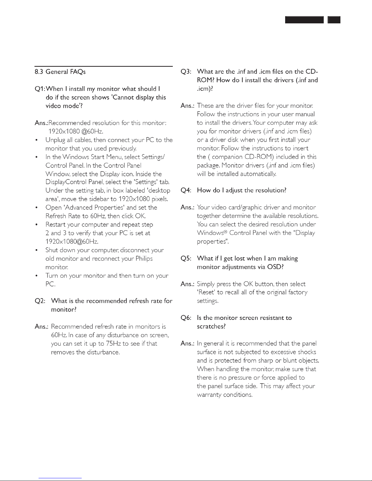
241P3 LCD 17
FAQs (Frequently Asked Questions)
18 241P3 LCD
FAQs (Frequently Asked Questions)
241P3 LCD 19
Electrical Instructions
Electrical characteristics
1. Interface signals
1.1 D-Sub Analog
Input signal: Video, Hsync., Vsync
Video: 0.7 Vp-p, input impedance, 75 ohm @DC
Sync.: Separate sync TTL level , input impedance 2.2k ohm terminate
Hsync Positive/Negative
Vsync Positive/Negative
Composite sync TTL level, input impedance 2.2k ohm terminate
Sync on green video 0.3 Vp-p Negative (Video 0.7 Vp-p Positive)
1.2 DVI-D Digital
Input signal: Single TMDS link (Three channels: RX0-/+, RX1-/+, RX2-/+)
1.3 Audio
Input signal: 1000 mVrms
Loudspeaker (Impedance: 5.25 Ohm +/-15%): 1.5W+ 1.5 W (typical) , stereo for RMS
1.4 USB PLUG
USB port (1 upstream, 1 downstream), black jack color
2. Interface
2.1 D-Sub Cable
Length : 1.8 M +/- 50 mm
Fix with monitor when packing, with transplant pin protective cover.
Connector type : D-Sub male with DDC2B pin assignments.
Blue connector thumb-operated jack screws
2.2 DVI Cable
The input signals are applied to the display through DVI-D cable.
Length : 1.8 M +/- 50 mm
Connector type : DVI-D male with DDC-2B pin assignments
White connector thumb-operated jackscrews
With transplant pin protective cover.
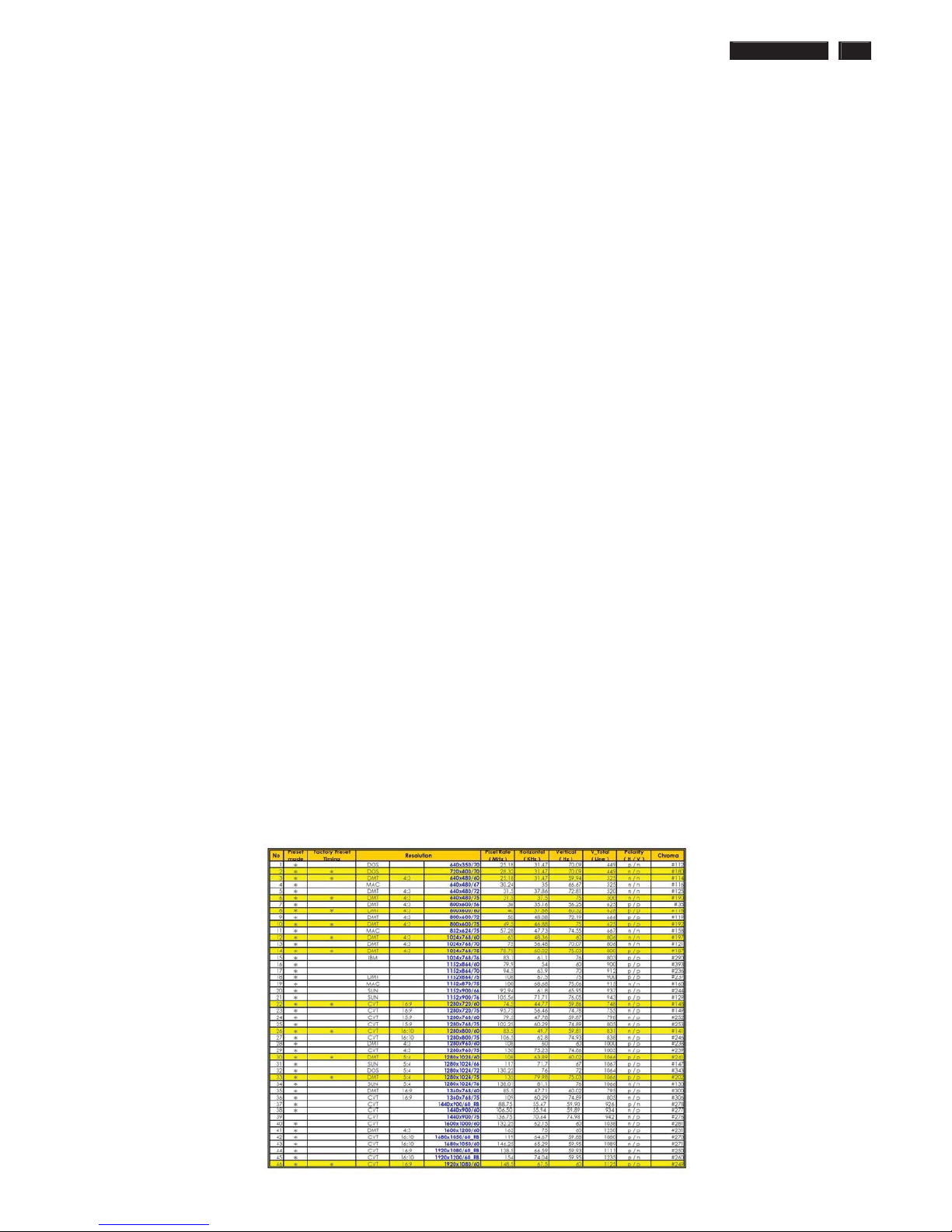
3. Timing requirement
3.1 Factory Preset mode definition:
3.1.1 Perfect FOS while presenting those timings.
3.1.2 Will specify those timing in User's Manual
3.2 Preset mode definition:
3.2.1 Need to support those timings.
3.2.2 Perfect FOS after auto adjustment.
3.3 User mode
3.3.1 Can save those timing that not in Preset mode and can be showed
(not over scalar or Panel spec.)
3.3.2 It needs to reserve the 10 timings space in memory size.
3.3.3 Factory modes and preset modes are defined in the enclosed timing table file
20 241P3 LCD
Electrical Instructions
White color adjustment
There are three factory preset white color 9300K, 6500K, sRGB.
Apply full gray64 pattern, with brightness in 100 % position and the contrast control at 50 % position.The 1931 CIE
Chromaticity (color triangle) diagram (x ,y) coordinate for the screencenter should be:
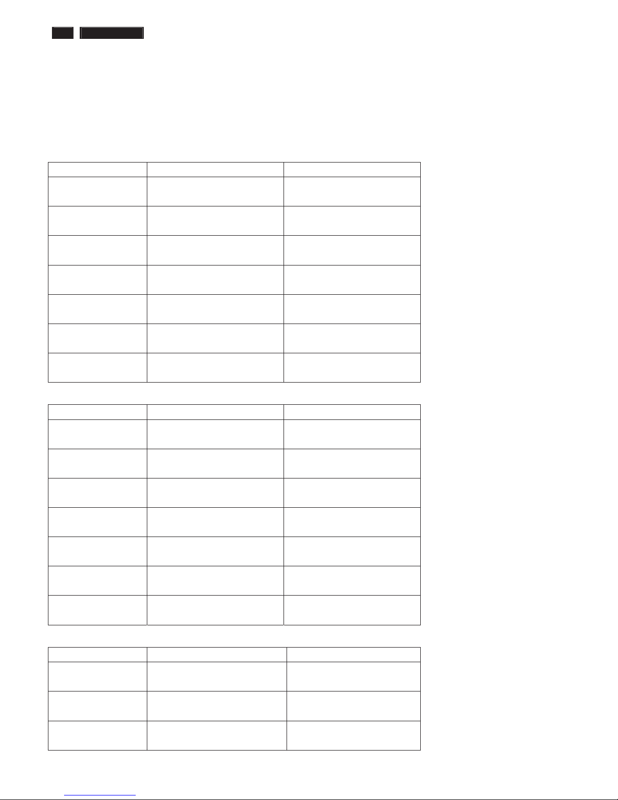
Product specification
CIE coordinates (x,y)
11500K x = 0.270 ± 0.02
y = 0.281 ± 0.02
PerfectuneII
9300K x = 0.283 ± 0.02
y = 0.297 ± 0.02
PerfectuneII
8200K x = 0.291 ± 0.02
y = 0.306 ± 0.02
PerfectuneII
7500K x = 0.298 ± 0.02
y = 0.314 ± 0.02
PerfectuneII
6500K/sRGB x = 0.313 ± 0.02
y = 0.329 ± 0.02
PerfectuneII
sRGB x = 0.313 ± 0.02
y = 0.329 ± 0.02
PerfectuneII
5000K x = 0.345 ± 0.02
y = 0.357 ± 0.02
PerfectuneII
Production alignment spec.
CIE coordinates (x,y)
11500K x = 0.270 ± 0.006
y = 0.281 ± 0.006
PerfectuneII
9300K x = 0.283 ± 0.006
y = 0.297 ± 0.006
PerfectuneII
8200K x = 0.291 ± 0.006
y = 0.306 ± 0.006
PerfectuneII
7500K x = 0.298 ± 0.006
y = 0.314 ± 0.006
PerfectuneII
6500K/sRGB x = 0.313 ± 0.006
y = 0.329 ± 0.006
PerfectuneII
sRGB x = 0.313 ± 0.006
y = 0.329 ± 0.006
PerfectuneII
5000K x = 0.345 ± 0.006
y = 0.357 ± 0.006
PerfectuneII
Quality Inspection specification:
CIE coordinates (x,y)
9300K x = 0.283 ± 0.015
y = 0.297 ± 0.015
6500K/sRGB x = 0.313 ± 0.015
y = 0.329 ± 0.015
sRGB x = 0.313 ± 0.015
y = 0.329 ± 0.015
241P3 LCD 21
Service tool-Hardware
PCM code 12NC
5E.L8215.001 996510019769
22 241P3 LCD
Service tool-Software
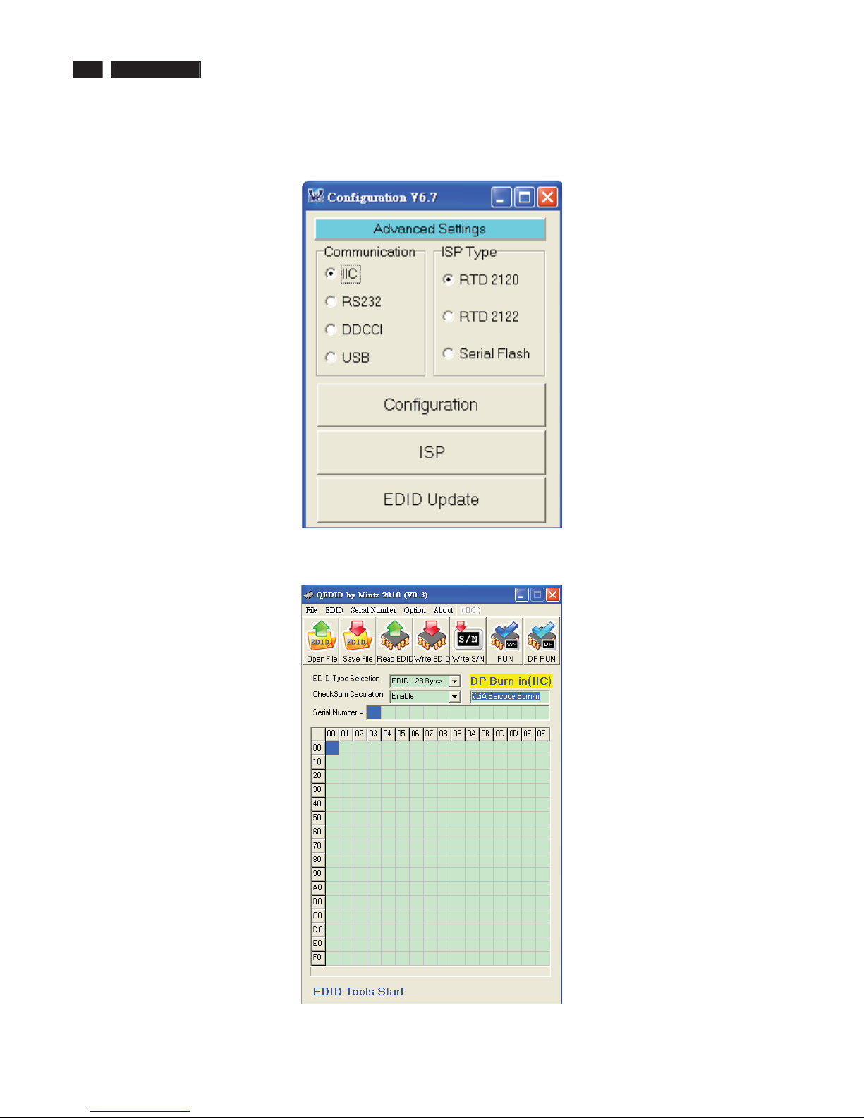
FW writing tool: RTD tool V6.7
DDC writing tool: Q-EDID-V30
241P3 LCD 23
DDC Instructions
DDC Data Re-programming
In case the DDC data memory IC or main EEPROM which storage all factory settings were
replaced due to a defect, the serial numbers have to be re-programmed "Analog
DDC IC, Digital DDC IC & EEPROM".
It is advised to re-soldered DDC IC and main EEPROM from the old board onto the new
board if circuit board have been replaced, in this case the DDC data does not need to be
re-programmed.
Additional information
Additional information about DDC (Display Data Channel) may be obtained from Video
Electronics Standards Association (VESA).
Extended Display Identification Data(EDID) information may be also obtained from
VESA.
Configuration and procedure
"PI-EDID" The software is provided by IMS to upgrade the firmware of CPU.
PI-EDID Tools is for the interface between "Parallel Port of PC" and "15 pin-D-SUB
connector of Monitor".
It is a windows-based program, which cannot be run in MS-DOS.
System and equipment requirements
1. An Pentium (or above) personal computer or compatible.
2. Microsoft operation system Windows 95/98/2000/XP and Port95NT.exe.
3. EDID Software "QEDID.exe"
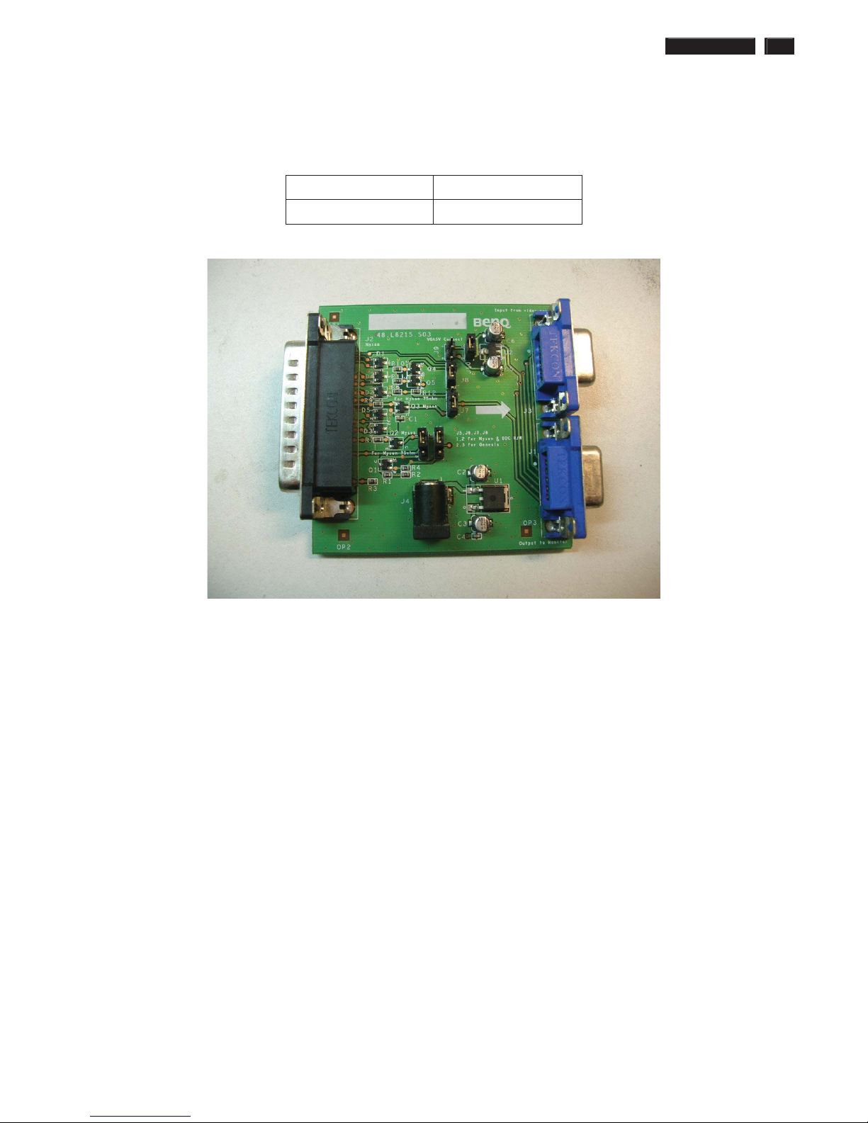
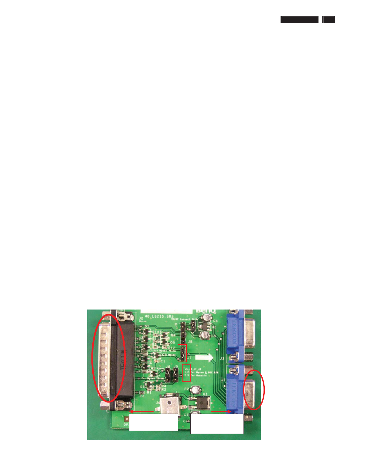
4. ISP boardas shown in Fig. 1
And I2C Board Jump wire should follow J10 (short), J9 (open), J5/J6/ (1and 2 pin short)
J7/J8 (1 and 2 pin short)
Connected to print
cord and PC
Connected to Display
Signal Cable
1
2
3
2
Fig.1
24 241P3 LCD
DDC Instructions
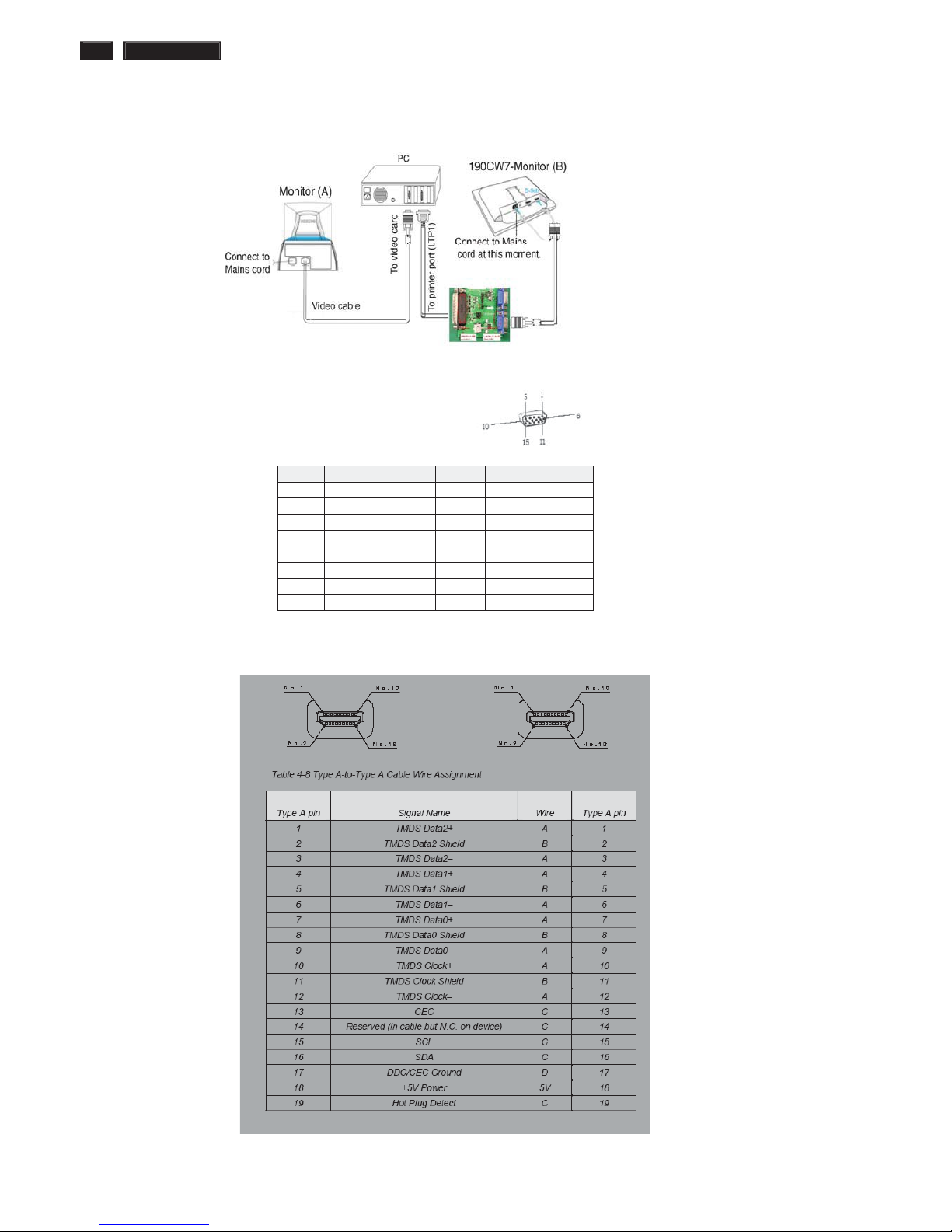
5. Connect and Mains cord to Monitor as shown in Fig.2.
Fig.2
Pin assignments :
A. 15-pin D-Sub Connector
B. Input HDMI Connector pin
PIN No. SIGNAL PIN No. SIGNAL
1 Red 9 DDC +3.3V or +5V
2 Green/ SOG 10 Logic GND
3 Blue 11 Sense (GND)
4 Sense (GND) 12 Bi-directional data
5 Cable Detect (GND) 13 H/H+V sync
6 Red GND 14 V-sync
7 Green GND 15 Data clock
8 Blue GND
ʳʳ
241P3 LCD 25
DDC Instructions
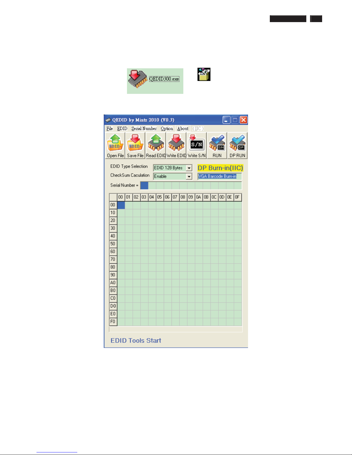
6. Setup the Philips-IMS EDID Tools program
Step 1: Open Q-EDID V030 Software into your folder as shown in Fig.3. and Fig.4.
ˤ˘˗˜˗ˆ˃˃ˁ˸˸
Fig.3
Fig.4
26 241P3 LCD
DDC Instructions
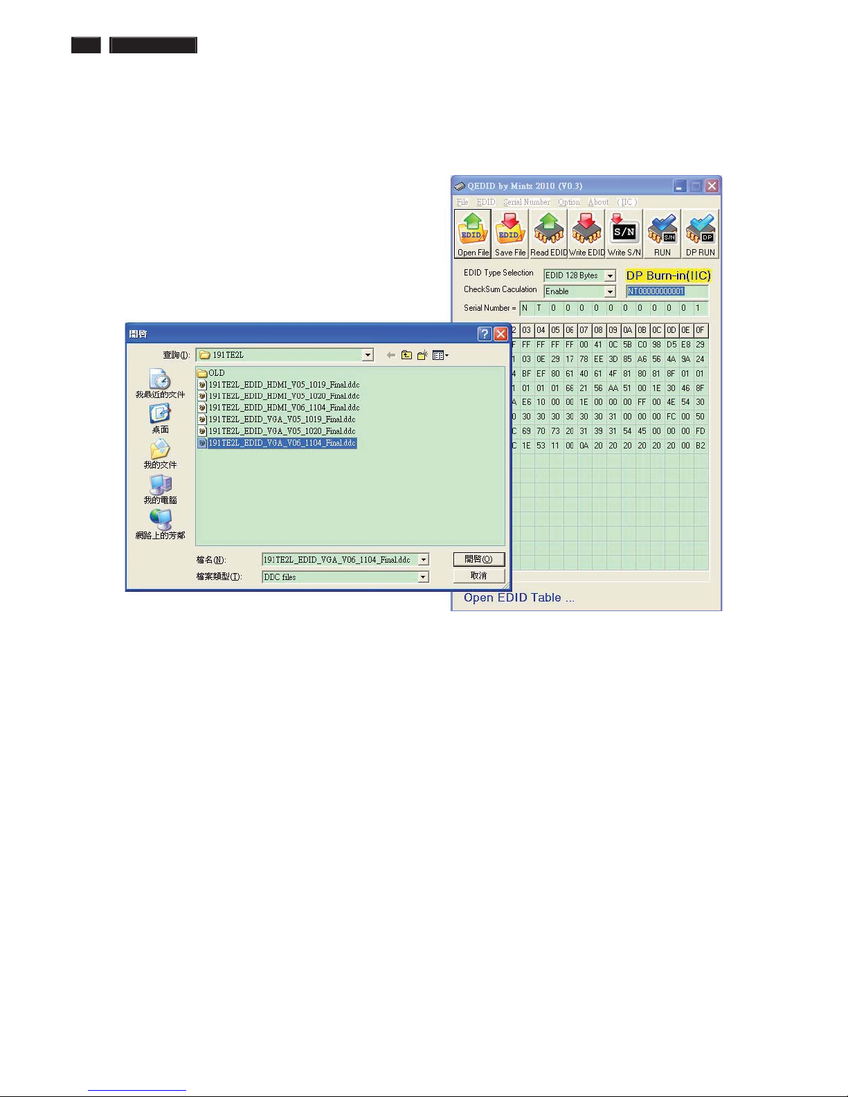
Step 2: Press “Open File” then choose
241P3 DDC FILE
Fig.5
241P3 LCD 27
DDC Instructions
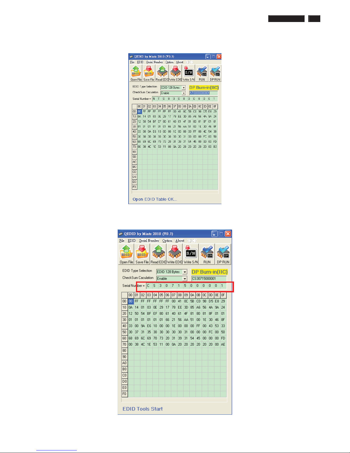
Step 3 : Load DDC file success as shown in Fig. 6 .
Fig.Step 4 : update Serial number and press enter to correct S/N number
shown as Fig.7 .
Fig.7
28 241P3 LCD
DDC Instructions
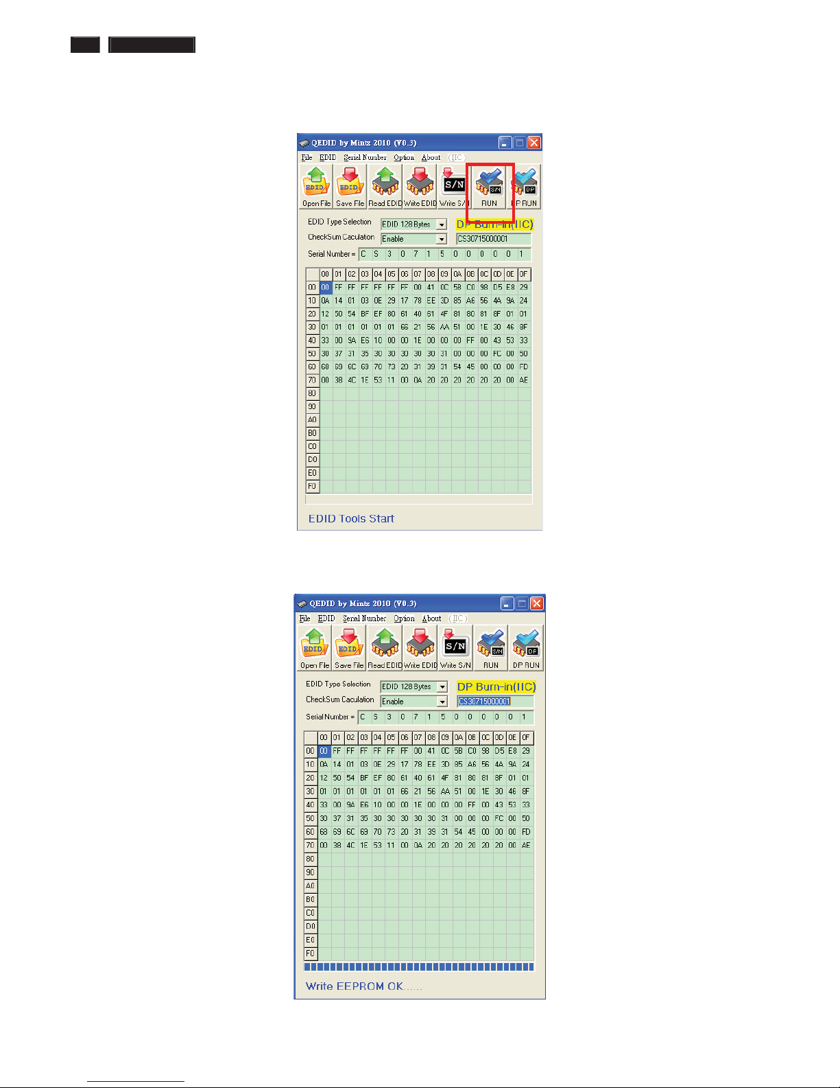
Step 5 : Press “RUN” to write EDID and serial number shown as Fig.8 .
Fig.8
Step 6 : EDID and serial number update success shown as Fig.9
Fig.9
 Loading...