

Philips 241B4PYCB/01, 241B4PYCS/01, 241B4PYCB/27, 241B4PYCB/69, 241B4PYCB/75 Service Manual
...
Description Page
Important Safety Notice--------------------------------------2
Technical Data--------------------------------------------- ----3
Installation----------------------------------------------------4~5
On Screen Display------------------------------------------8~9
Lock/unlock, Aging,Factory mode-------------------------10
---------------------------------11
Mechanical Instructions ------------------------------12~14
Color adjustment --------------------------------------------15
Electrical instruction ----------------------------------18~19
DDC Instructions & Serial Number -----------------22~28
DDC DATA -----------------------------------------------29~30
------------------------31~32
Philips Pixel Defect Policy
FAQs (Frequently Asked Questions)---------------16~17
Firmware Upgrade for CPU-
Horizontal frequencies
30-83kHz
TABLE OF CONTENTS
Description Page
-----------------------------------33
Wiring
Diagram----------------------------------------------34
Failure Mode Of Panel -
SAFETY NOTICE
Chassis:
24
REFERTO BACK COVER FOR
IMPORTANT SAFETY GUIDELINES
ANY PERSON
ATTEMPTING TOSERVICE THIS CHASSIS
MUST FAMILIARIZE
HIMSELF
WITH THE
CHASSIS
AND BE AW ARE OF THE NECESSAR Y SAFETY PRECAUTIONS
TO BE USED WHEN
SERVICING ELECTRONIC
EQUIPMENT CONTAINING
HIGH VOLTAGES.
CAUTION:
USE
A SEPARATE
ISOLATION TRANSFORMER FOR THIS UNIT WHEN SERVICING.
PublishedbyPhilipsConsumerLifestyleCopyrightreservedSubjecttomodificationJ May 06 2014
GB
MERIDIAN 4
Troubleshooting---------------------------------------------6~7
Service Tool-----------------------------------------------20~21
241B4LPYCS/00
inch FHD
LCD Colour Monitor
TFT
241B4LPYCS/00(AP)
241B4LPYCS/01
241B4LPYCB/00
241B4LPYCB/00(AP)
241B4LPYCB/01
241B4LPYCB/27
241B4LPYCB/69
241B4LPYCB/75
241B4LPYCB/96
Block Diagram------------------------------------------------35
Power
Control Diagram & C.B.A. -----------------------------45~46
Scaler Diagram & C.B.A. ------------------------------36~41
General product specification------------------------57~76
Exploded View -----------------------------------------------77
Spare/ arts List-------------------------78
Recommended P
PCBA photos---------------------------------------------------79
Repair tips-------------------------------------------------80~81
Repair Flow chart----------------------------------------82~83
Safety Test Requirments------------------------------------84
Diagram
& C.B.A.
------------------------------42~44
BZL&CTRL BD Replace ---------------------------------------85
Auto Color & User reset
--------------------------------86~87
Tx
Diagram & C.B.A.--------- -------------------------51~52
Jack
Diagram & C.B.A.--------- -------------------------53~54
USB
Diagram & C.B.A.--------- -------------------------55~56
IR
Diagram & C.B.A.--------- -------------------------49~50
LED
Diagram & C.B.A.--------- -------------------------47~48
241B4LPYCB/79

Important Safety Notice
Proper service
operation of all Philips Consumer Electronics Co
mpany
equipment. The service procedures
re
commended by
Phil
ips and
described in this service manual a
re eff
ect
ive method
sof
performing service ope
rations
.Someof
these servic
e
operations require the useof tools speciall y designed
for the
purpose. The spe
cial tools should be used w
hen and as
recomm ended.
It is im portant to note t hat this m anual c ontains various
CAUTI ON
S and NOTICES which should be
carefully read in
order to m inimize the risk of personal injury to servic
e
personnel . The possibility exists th
at im
proper
servi
ce
methods may damage the equipment
. It is also important t
o
underst and that these CAUTIONS and NOTICES ARE NOT
EXHAUSTIVE. Phil
ips
could not poss ibly know, evaluate and
advise the servic etrade of all conceivable ways i n w
hic
h
service might be done or of the possible hazardous
consequences of each way. Consequently,Philips has not
undertaken any suc
h broad evalua
ti
on. Accordingly
,
who uses a servi ce procedure or tool which is not
recommended by Philipsmust f
irst sati
sfy
himself thoroughly that
neither his saf ety nor the safeoperation of the equipment will
be jeopardized by the servi
ce method sel
ect ed.
* * Hereafter throughout this manu
al,
PhilipsConsumer
Electronics Company will be referred to as Philips
.
**
Critical components havingspecial safety characteristics are
identified with a by the Ref. No. in the parts list and
enclosed within a broken line
(where several critical co
mponents are grouped in
one area)
along with t
he safe
ty s
y
mbol on the schem atics
or
exploded vie
ws.
Use of substitute replacement parts w hich do no
t have the
same speci fied safety characteristic s may create
shock,
fire,
or other hazards .
Under no cir cumstances should th
e original
design be
modified or altered without written permission from Philip
s.
Philips assumes no liabilit
y, express or implied, arising
out of
any unauthorized modification of design.
Servicer assumes all liability.
WARNING
Take care during handling the LCD module with backlight
unit
- Must mount the module using mounting holes arranged in four
corners.
- Do not press on the panel, edge of the frame strongly or electric
shock as this will result in damage to the screen.
- Do not scratch or press on the panel with any sharp objects, such
as pencil or pen as this may result in damage to the panel.
- Protect the module from the ESD as it may damage the electronic
circuit (C -MOS).
-
Make certain that treatment body are grounded through
wrist band.
- Do not leave the module in high temperature and
in areas of high
humidity for a long time.
- Avoid contact with water as it may as hort circuit within the module.
-
If the surface of panel become dirty
, please wi
pe it off with a soft
material. (Cleaning with a dirty or rough cloth may damage the
panel.)
FOR PRODUCTS CONTAINING LASER :
DANGER - Invisible laser radiation when open.
AVOID DIRECT EXPOSURE T
O BEAM.
CAUTION - Use of controls or adjustments or
performance of procedures other than
those specified herein may result
in
hazardous radiation exposure.
CAUTION - The use of optical instruments with this
product will increase eye hazard.
TO ENSURE THE CONTINUED RELIABILITY
OF THIS
PRODUCT, USE ONLYORIGINAL
MANUF
ACTURER'S
REPLACEMENT PAR TS, WHICH ARE LISTED WITH THEIR P
ART
NUMBERS IN THE PAR
TS LIST SECTION OF
THIS
SERVICE MANUAL.
and repair is important
to the sa
fe,
reliable
2 241B4LPY LCD
241B4LPY LCD 3
Technical Data
AUO
Type NR. : AUO M240HW01 VD
Resolution : 1920 x 1080 (FHD)
Outside dimensions
: 556.0(H) x 323.2(V) x 11.5(D) mm
Pitch (mm) : 0.27675mm x 0.27675mm
Color pixel arrangement
: 1920 horiz. by 1080 vert. Pixels. RGB
stripe arrangement
Display surface : Hard coating (3H), Anti-glare treatment
Color depth
: 16.7 M colors 8-bit with A-FRC, 16.7M
colors
Backlight : WLED
Active area (W x H) : 521.28mm (H) ×293.22mm ( V) mm
View angle (CR=10) : >=170 for Right/Left (Typ)
: >=160 for Up/Down (Typ)
Contrast ratio : >=1000:1 (Typ)
White luminance : 250 (center,Typ)
Color gamut
: >=72% (Typ.)
Response time : 5 ms (Typ)
Vertical frequency range : 47~75 H z
Scanning frequencies
Hor.: 30 – 83 K Hz
Ver.: 50 - 76 Hz
Analog : Support RGB WUXGA 1920x1200@60,
2048x1152@60hz input for NT68668UMFG
205Mhz HPLL With 64 steps phase Adjust for RGB Channel in
NT68668UMFG
Digital : Integrated Single Link TMDS Receiver up To 225MHz
deep color mode
Power range: FULL RANGE POWER SUPPLY 90 – 264 VAC
Ambient temperature: 0 qC - 40 qC
Power input connection
Power cord length : 1.8 M
Power cord type : 3 leads power cord with protective earth plug.
Power management
Mode HS
YN
C
VSYNCVideo Pwr-cons.Indication Rec.
time
Power-On On On Active
<32W(ma
x.)<
<45W(ma
x.)
EPA5.0 <
33.97W
White LED --
Standby Off Off Blanked < 0.2W
Blinking white
LED
Period 1sec on
3sec off
<3s
DC Power
Off
ʳʳ N/A < 0.2 W LED Off ʳ
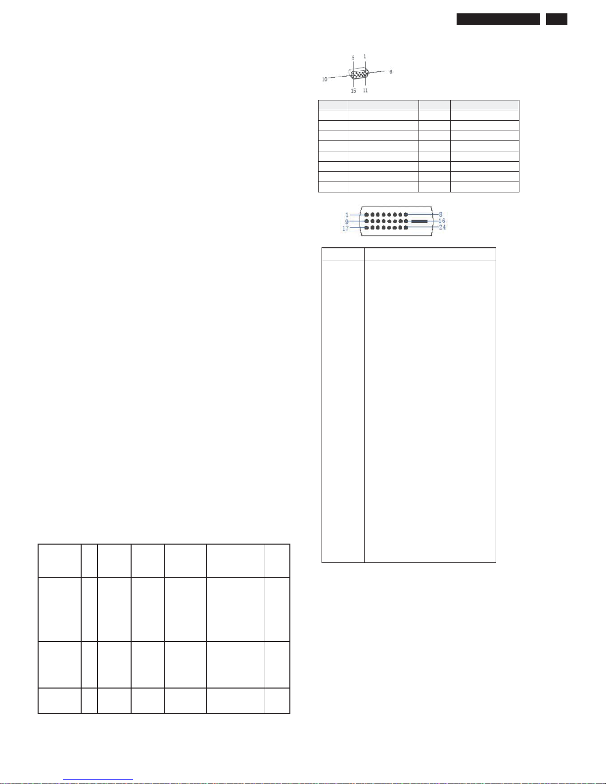
PIN No. SIGNAL PIN No. SIGNAL
1 Red 9 DDC +3.3V or +5V
2 Green/ SOG 10 Logic GND
3 Blue 11 Sense (GND)
4 Sense (GND) 12 Bi-directional data
5 Cable Detect (GND) 13 H/H+V sync
6 Red GND 14 V-sync
7 Green GND 15 Data clock
8 Blue GND
ʳʳ
Susceptibility of display to external environment
Operating
- Temperature : 0 to 40 degree C
- Humidity :80% max
- Altitude :
0-3658m
- Air pressure : 600-1100 mBAR
Storage
- Temperature : -20 to 60 degree C
- Humidity : 95% max
- Altitude : 0-12192m
- Air pressure : 300-1100 mBAR
Note: recommend at 5 to 35qC, Humidity less than 60 %
Pin No. Description
1 T.M.D.S. data22 T.M.D.S. data2+
3 T.M.D.S. data2 shield
4 No Connect
5 No Connect
6 DDC clock
7 DDC data
8 No Connect
9 T.M.D.S. data110 T.M.D.S. data1+
11 T.M.D.S. data1 shield
12 No Connect
13 No Connect
14 +5V Power
15 Ground (for +5V)
16 Hot plug detect
17 T.M.D.S. data018 T.M.D.S. data0+
19 T.M.D.S. data0 shield
20 No Connect
21 No Connect
22 T.M.D.S clock shield
23 T.M.D.S. clock+
24 T.M.D.S. clock-
4 241B4LPY LCD
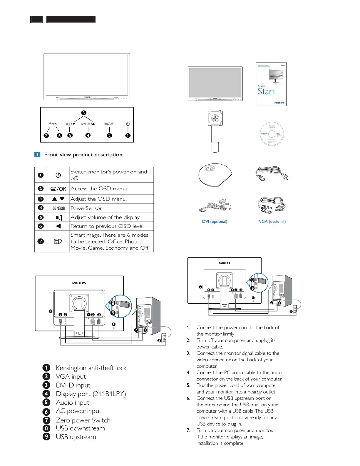
Installation
Front View Product Description Accessory Pack
Unpack all the parts
Connecting to Your PC
1) Connect the power cord to the back of the monitor firmly.
(Philips has pre-connected VGA cable for the first installation.
ʳ
Rear Vi
ew
ʳ
241B4LPY LCD 5
Troubleshooting
ʳ
6 241B4LPY LCD
Troubleshooting
241B4LPY LCD 7
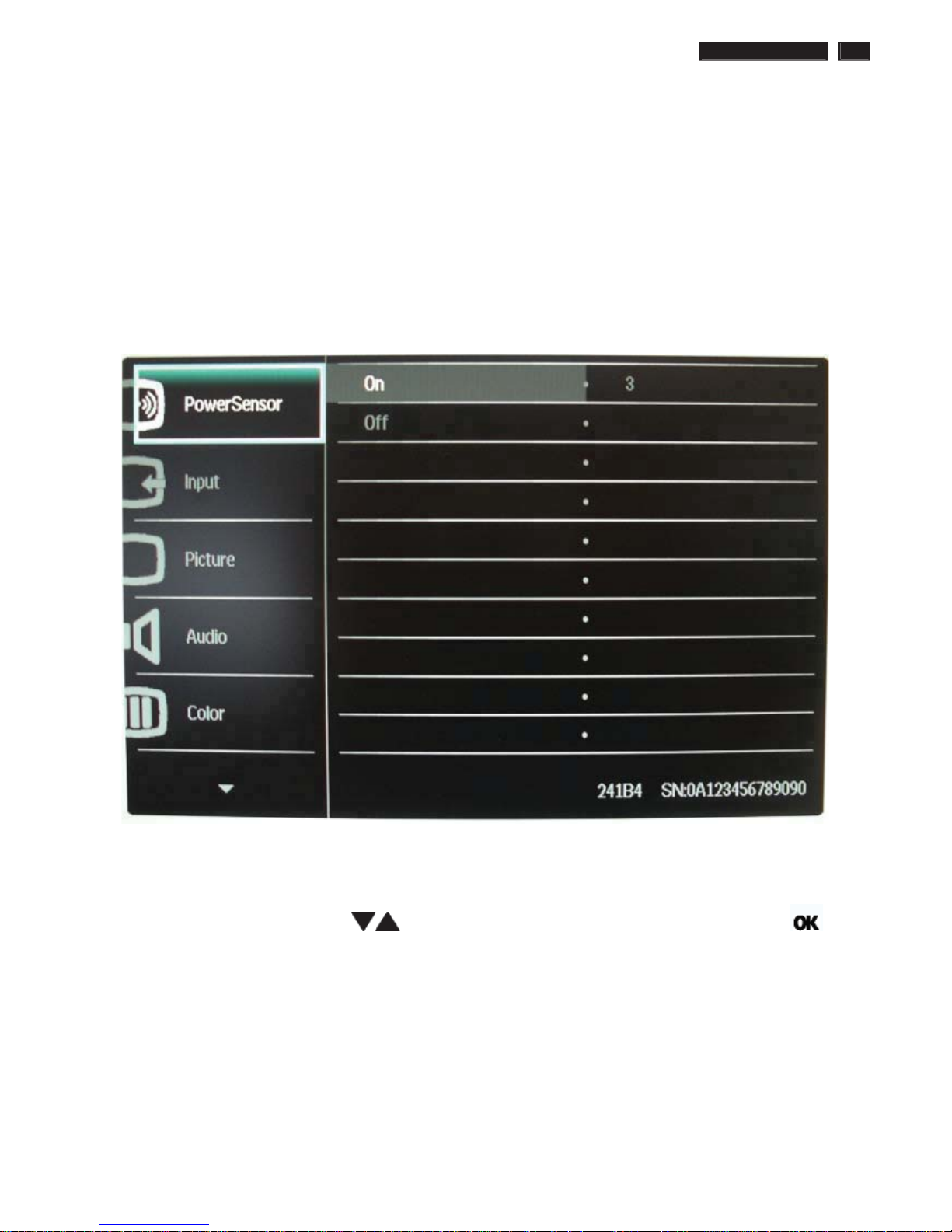
On-Screen Display
Description of the On Screen Display
ʳ
What is the On-Screen Display?
ʳ
On-Screen Display (OSD) is a feature in all Philips LCD monitors. It allows an end user to adjust screen performance or
select functions of the monitors directly through an on-screen instruction window. A user friendly on screen display
interface is shown as below :
ʳ
ʳ
Basic and simple instruction on the control keys.
ʳ
In the OSD shown above users can press buttons at the front bezel of the monitor to move the cursor, to
confirm the choice or change.
ʳ
ʳʳ
8 241B4LPY LCD
On-Screen Display
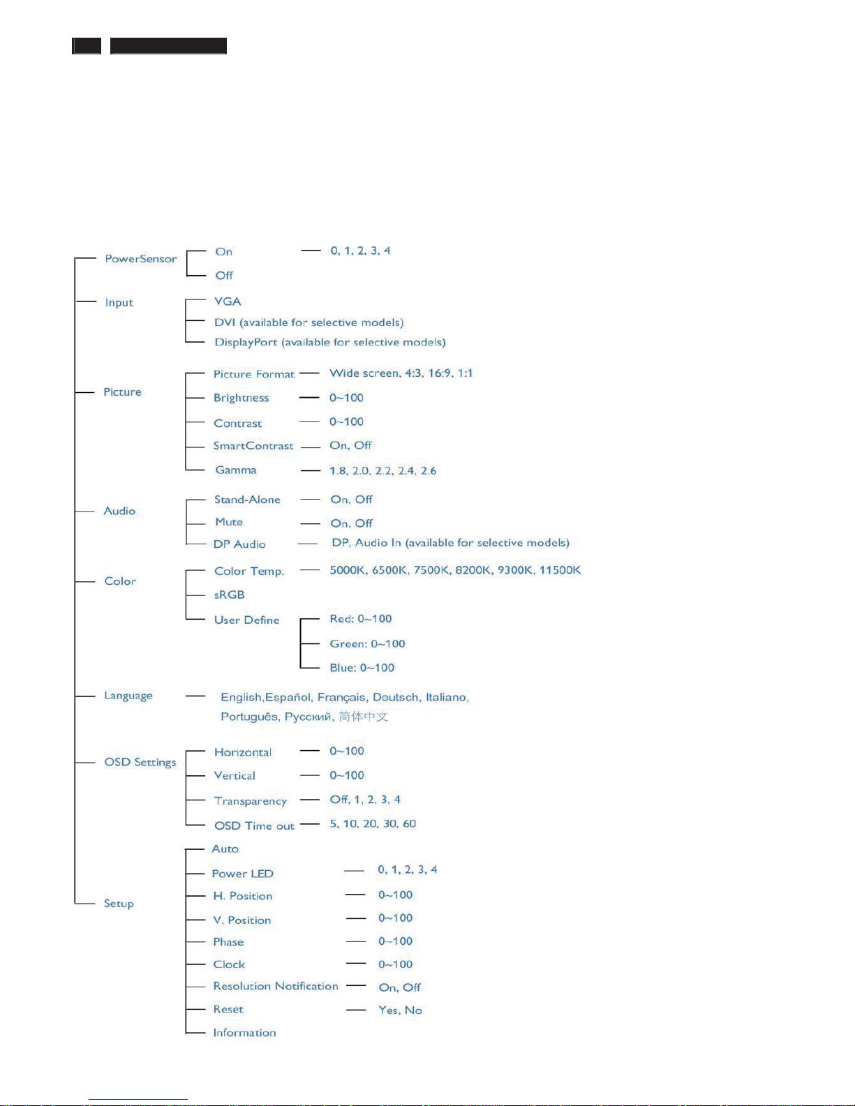
The OSD Tree
ʳ
Below is an overall view of the structure of the On-Screen Display. You can use this as a reference when you want to work
your way around the different adjustments later on.
ʳ
ʳ
241B4LPY LCD 9
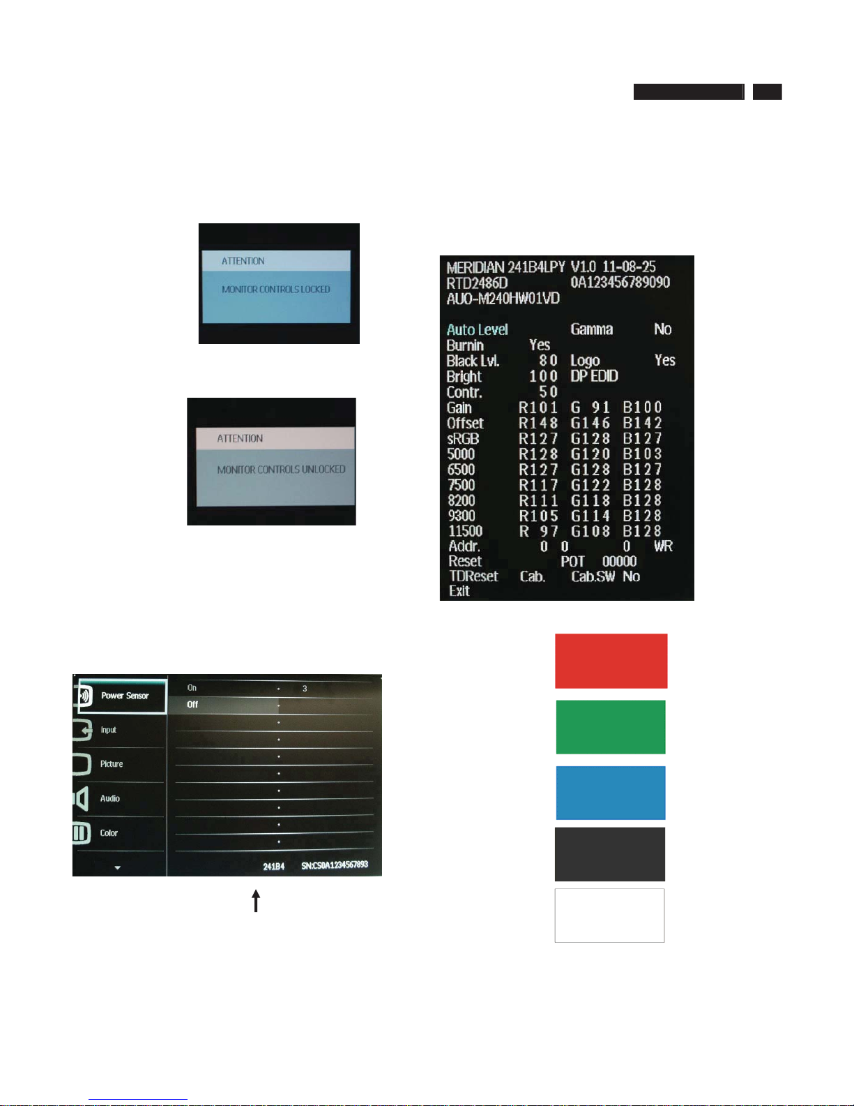
/RFN8QORFN$JLQJ)DFWRU\0RGH
To lock/unlock OSD FUNCTION(User Mode)
The OSD function can be locked by pressing"OK"button(1) for more than 10
seconds, the screen shows following windows for 4 seconds. Every time
when you press"OK" button, this message appears on the screen
automatically .
Unlock OSD function
Unlocked OSD function can be released by pressing "OK" button for more
than 10 seconds again.
$FFHVV)DFWRU\0RGH
1). Turn off monitor.
2).[Push "EXIT" & "MENU" buttons at the same time and hold them]+[Press
"power" button until comes out "Windows screen" ]=> then release all
buttons
3).Press "MENU" button, wait until the OSD menu with Characters
"MERIDIAN 241B4LPY V1.0 2011-08-25” (below OSD menu) come on the
Screen of the monitor.
Factory Mode indicator
Factory Menu
Cursor can move on gray color area
Hot key function: by pressing " UP " and " DOWN " key Simultaneously at
User Mode (or Factory Mode) (PS: The Of fset R G B function can be used
on reduce or eliminate snowy noise on the background when the resolution
of video signal is 1280*1024vertical 75Hz. Slightly increase or decrease the
value until snowy noise completely disappear .
$FFHVV$JLQJ0RGH
Step 1 : Access Factory Mode then enter Factory Menu.
Step 2 : By pressing " UP" and " DOWN " key to Burning Icon. Press
"MENU then press " UP" and "DOWN " key to turn on Aging Mode.
Step 3 : Disconnect interface cable between Monitor and PC.
After 3 seconds,
bring up:
repeatly
Connect Signal cable again=> go back to normal display
10 241B4LPY LCD
Philips Pixel Defect Policy
ʳ
Philips' Flat Panel Monitors Pixel Defect Policy
ʳ
Black Dot Defects Black dot defects appear as pixe
ls or sub pixels that are
always dark or 'off'. That is, a dark dot is a sub-pixel that stands out on the
screen when the monitor displays a light pattern. These are the types of
black dot defects:ʳ
Philips strives to deliver the highest quality products. We use some of the
industr
y's most advanced manufacturing processes and practice stringent
quality control. However, pixel or sub pixel defects on the TFT LCD panels
used in flat panel monitors are sometimes unavoidable. No manufacturer
can guarantee that all panels will be free from pixel defects, but Philips
guarantees that any monitor with an unacceptable number of defects will be
repaired or replaced under warranty. This notice explains the different types
of pixel defects and defines acceptable defect levels for each type. In order
to qualify for repair or replacement under warranty, the number of pixel
defects on a TFT LCD panel must exceed these acceptable levels. For
example, no more than 0.0004% of the sub pixels on a 19" XGA monitor may
be defective. Furthermore, Philips sets even higher quality standards for
certain types or combinations of pixel defects that are more noticeable than
others. This policy is valid worldwide.
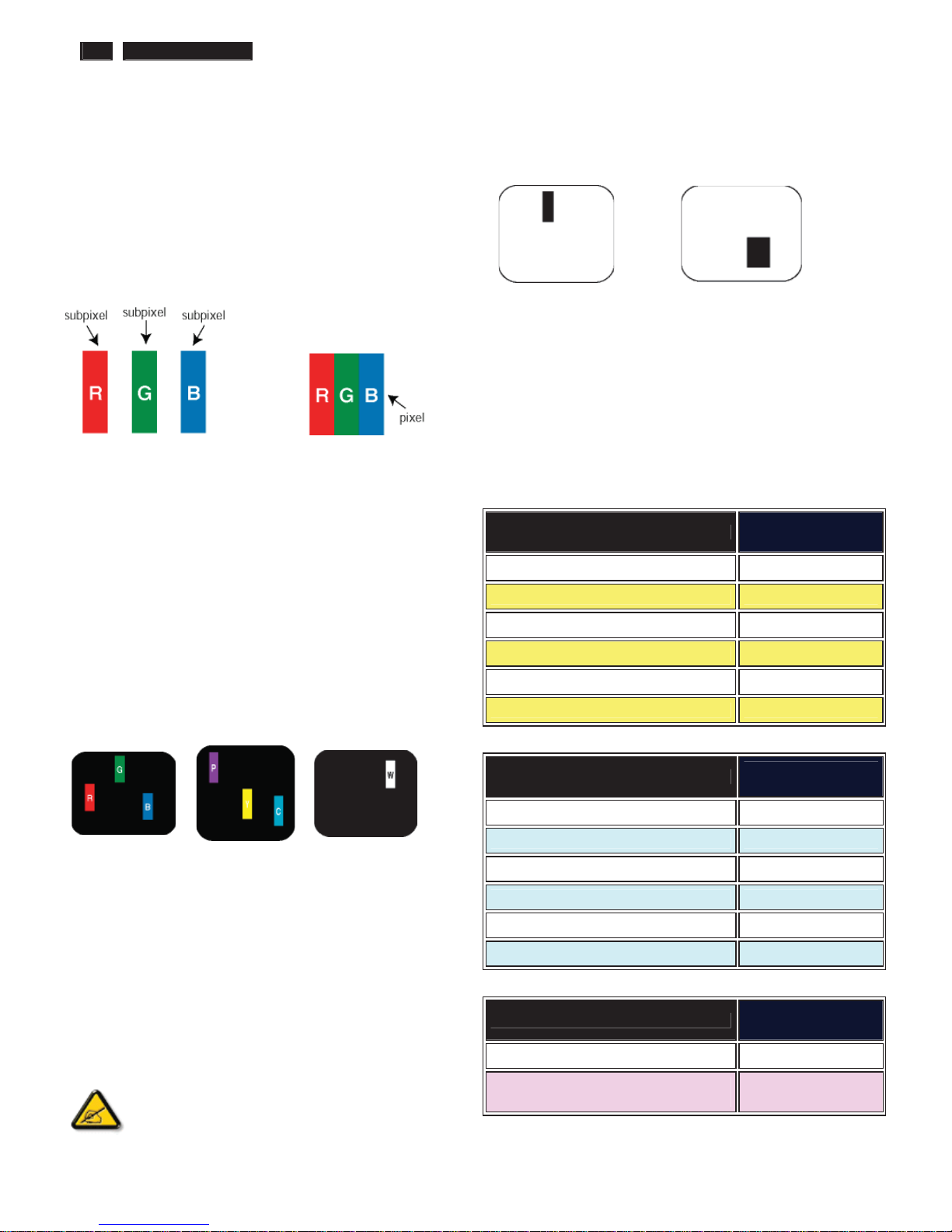
Pixels and Sub pixels
A pixel, or picture element, is composed of three sub pixels in the primary
colors of red, green and blue. Many pixels together form an image. When all
sub pixels of a pixel are lit, the three colored sub pixels together appear as a
single white pixel. When all are dark, the three colored sub pixels together
appear as a single black pixel. Other combinations of lit and dark sub pixels
appear as single pixels of other colors.
ʳTy pes of Pixel Defects
ʳ
Pixel and sub pixel defects appear on the screen in different ways. There are
two categories of pixel defects and several types of sub pixel defects within
each category. ʳ
Bright Dot Defects Bright dot defects appear as pixels or sub pixels that are
always lit or 'on'. That is, a bright dot is a sub-pixel that stands out on the
screen when the monitor displays a dark pattern. There are the types of
bright dot defects:ʳ
ʳ
ʳ
One lit red, green or
blue sub pixelʳ
Two adjacent lit sub
pixels:
- Red + Blue =
Purple
- Red + Green =
Yellow
- Green + Blue =
Cyan (Light Blue)!
Three adjacent lit sub
pixels (one white
pixel)ʳ
ʳ
A red or blue bright dot must be more than 50 percent brighter
than neighboring dots while a green bright dot is 30 percent
brighter than neighboring dots.ʳ
ʳ
One dark sub pixelʳ Two or three adjacent dark sub pixelsʳ
Proximity of Pixel Defects
ʳ
Because pixel and sub pixels defects of the same type that are near to one
another may be more noticeable, Philips also specifies tolerances for the
proximity of pixel defects.
Pixel Defect Tolerances
ʳ
In order to qualify for repair or replacement due to pixel defects during the
warranty period, a TFT LCD panel in a Philips flat panel monitor must have
pixel or sub pixel defects exceeding the tolerances listed in the following
tables.ʳ
BRIGHT DOT DEFECTSʳ
ACCEPTABLE
LEVEL ʳ
MODELʳ
241B4LP(Y)ʳ
1 lit subpixelʳ 3ʳ
2 adjacent lit subpixelsʳ 1ʳ
3 adjacent lit subpixels (one white pixel)ʳ 0ʳ
Distance between two bright dot defects*ʳ >15mmʳ
Total bright dot defects of all typesʳ 3ʳ
BLACK DOT DEFECTSʳ
ACCEPTABLE
LEVEL ʳ
MODELʳ
241B4LP(Y)
ʳ
1 dark subpixelʳ 5 or fewerʳ
2 adjacent dark subpixelsʳ 2 or fewerʳ
3 adjacent dark subpixelsʳ 0 ʳ
Distance between two black dot defects*ʳ >15mmʳ
Total black dot defects of all typesʳ 5 or fewerʳ
TOTAL DOT DEFECTSʳ
ACCEPTABLE
LEVEL ʳ
MODELʳ
241B4LP(Y)
ʳ
Total bright or black dot defects of all
typesʳ
5 or fewerʳ
Note:
* 1 or 2 adjacent sub pixel defects = 1 dot defect
241B4LPY LCD 11
Mechanical Instruction
Preparation before disassemble
1.Clean the room for disassemble
2.Identify the area for monitor
3.Check the position that the monitors be placed and the quantity of the monitor ;prepare the area for material flow;
according to the actual condition plan the disassemble layout
4.Prepare the implement, equipments, materials as bellow:
1) Press-fixture
2) working table
3) Screw-driver
4) knife*1
5) glove
6) cleaning cloth
7) ESD protection
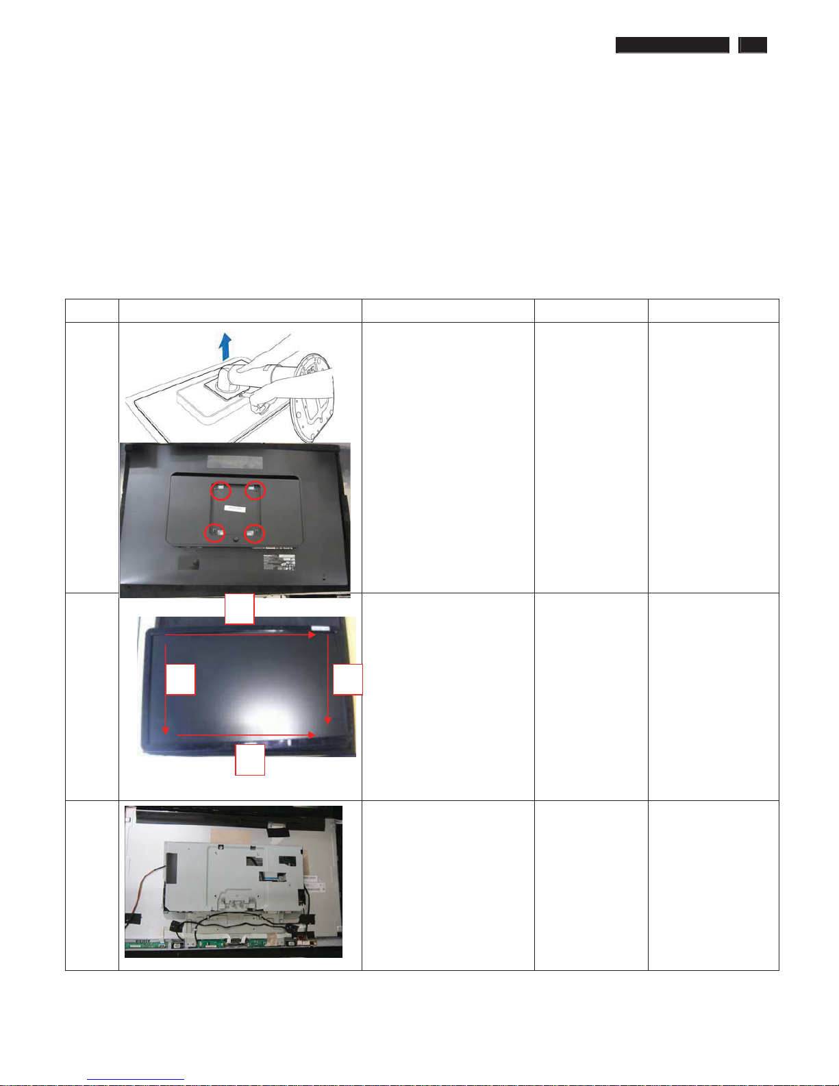
item picture Operation Tool Notes
1
Disassemble the Stand.
While keeping the release
button pressed, tilt the base
and slide it out.
Disassembly 4 screws,
Take off the stand .
Screw-driver
2 Turn over the monitor ,
Bring the Bezel from the
monitor
When disassembly
the bezel ,
notice don’t bend
the C/B .
man must wear
glove
The purpose is
loose the BZL
3 Remove the RC cover
4
3
2
1
12 241B4LPY LCD
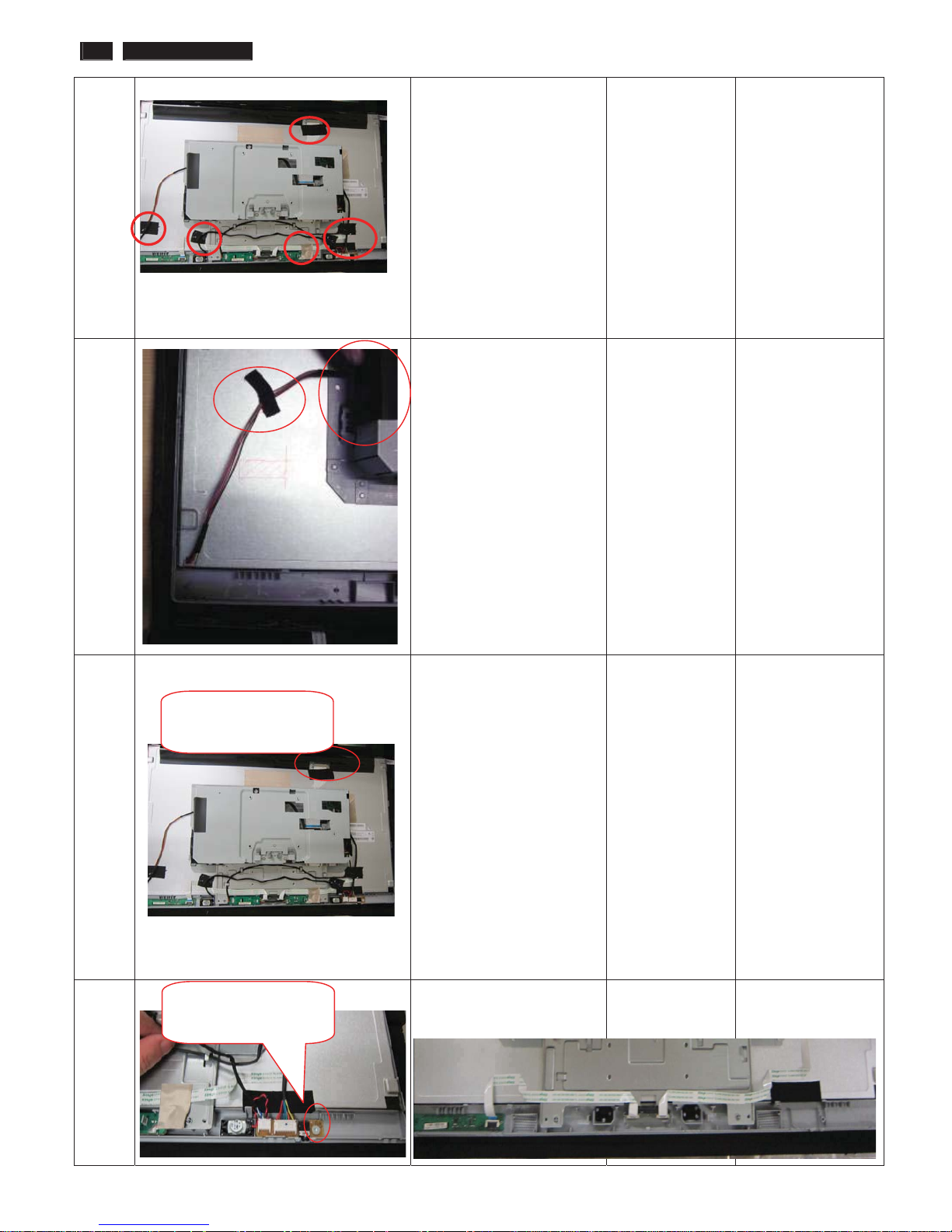
4 Remove all the Tapes on
each cable
5 Disassembly the Mylar on
lamp cables and draw the
lamp cables
6 Unlock the FFC by using
two hands(see note).
Please carefully use
two hands(one hand
presses the lockinglatch of FFC cable’s
housing, and at the
same time another
hand pulls out the
FFC cable.) for this
step to avoid from
deforming the
terminals of
positive-locking type
FFC cable.
7 Remove speaker and
remove the Audio BD
Screw-driver
The locking-latch
of FFC cable’s
Disassembly the
Au
d
io bd screw*1
241B4LPY LCD 13
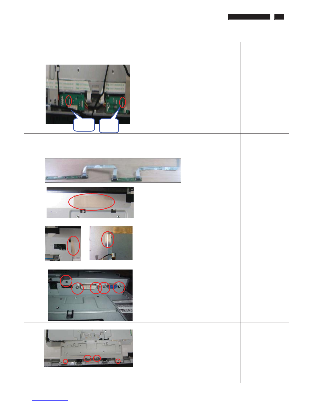
8 Remove IR bd TX bd
9 Disassemble the Control bd
and LED bd out from the
Bezel
10 Remove all the AL tapes
7;EG
,5
11 Disassemble the D-SUB
DVI and DP screws
Screw-driver
12 Take the Main-BKT out from
the Bezel
14 241B4LPY LCD
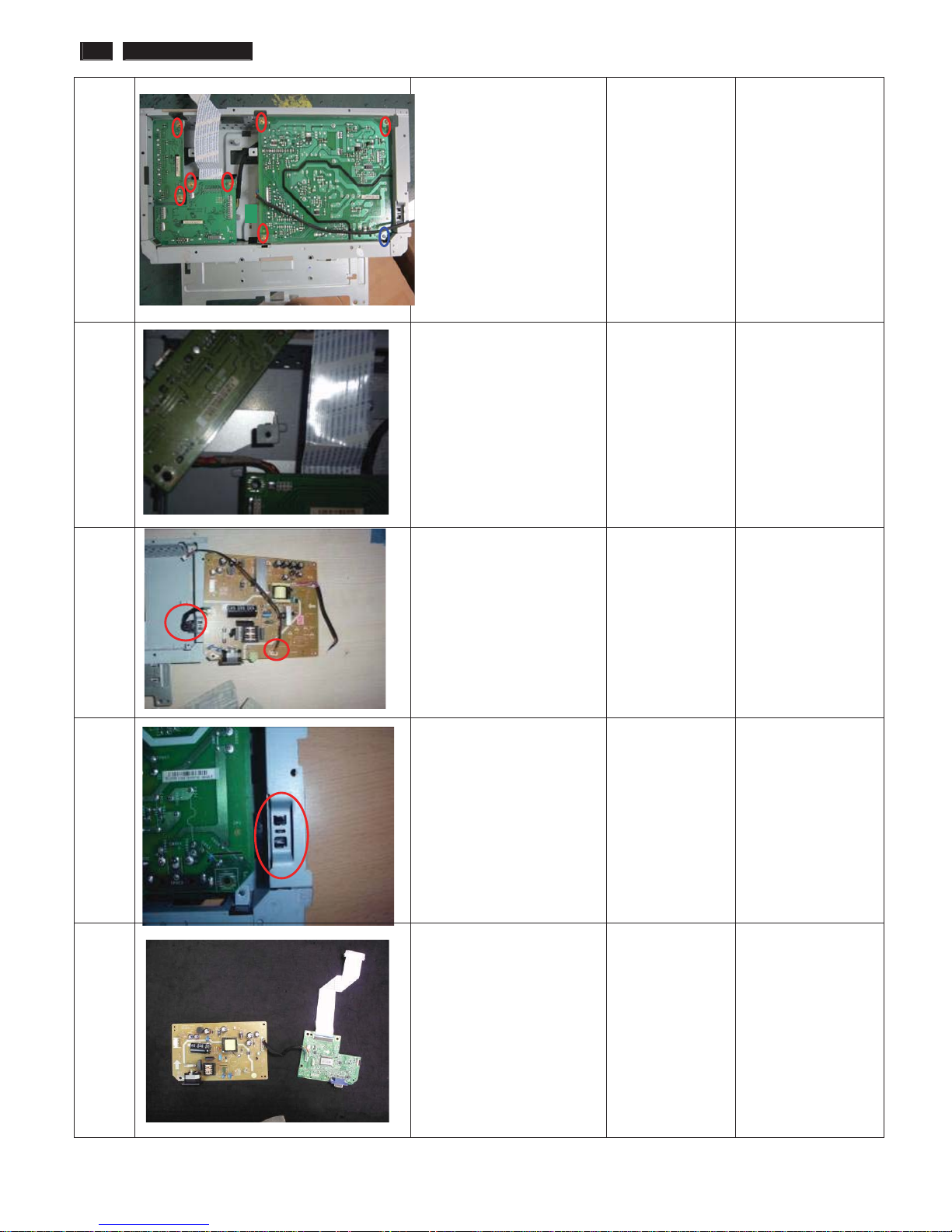
13 Turn over the Main-BKT
and Disassemble all the
PCBA bd screws*8
14 Remove the USB bd and
USB cable
15 Remove the AC-Switch and
all cables on Power bd
Screw-knife
16 Remove the AC-Switch
cover on Main-BKT
17 Take the PCBA out from
Main-BKT and then put it
on the cushion
241B4LPY LCD 15
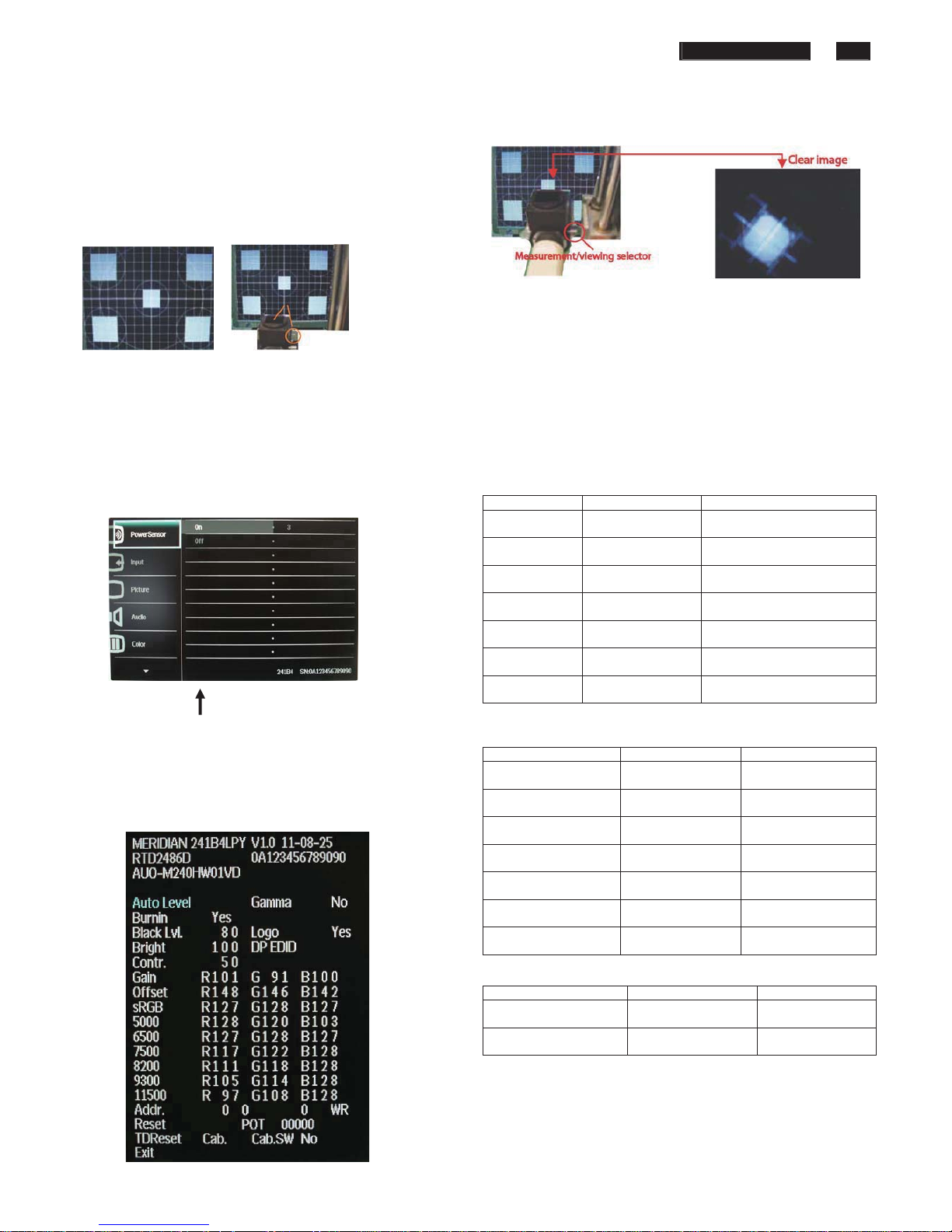
Color Adjustment
Alignment procedure
)LJ
1. Turn on the LCD monitor
2. Turn on the Timing/pattern generator. See Fig.1
3. Preset LCD co
lor Analyzer CA-1 10
-Remove the lens protective cover of probe CA-A30.
-Set measuring/viewing selector to measuring position for reset
analyzer .(zero calibration) as Fig.2
- Turn on the color analyzer (CA-1 10)
-Press 0-CAL button to starting reset analyzer .
Fig.5
5.Display
Press "UP" or "DOWN" button to select . Change the value
by "UP" or "DOWN" key until the X, Y co-ordinates as below
5.1 Color temperature adjustment
Fig. 1 Fig.2
There are six factory preset white color 11500K, 9300K, 8200K, 7500K,
6500K, sRGB, 5000K
4. Access F
actory Mode
Align by
Philips PerfecTune (also called FGA) function.
1). Turn off monitor.
Appl
y full white pattern, with brightness in 100 % position and the contrast
control at 50 % position.
2). [Push "AU
TO" & "MENU" buttons at the same time and hold them]
+[Press "power" button untill comes out "Windows screen" ]
The 1931 CIE Chromaticity (color triangle) diagram (x , y) coordinate for
the screen center should be:
=> then release
all buttons
3).Press "MENU button, wait until the OSD menu with
Characters " MERIDIAN 241B4LPY V1.0 2011-08-25” (below OSD menu)
come on the Screen of the monitor as shown in Fig3.
Product specification
CIE coordinates (x,y)
11500K x = 0.270 ± 0.02
y = 0.281 ± 0.02
PerfecTune II
9300K x = 0.283 ± 0.02
y = 0.297 ± 0.02
PerfecTune II
8200K x = 0.291 ± 0.02
y = 0.306 ± 0.02
PerfecTune II
7500K x = 0.298 ± 0.02
y = 0.314 ± 0.02
PerfecTune II
6500K/sRGB x = 0.313 ± 0.02
y = 0.329 ± 0.02
PerfecTune II
sRGB x = 0.313 ± 0.02
y = 0.329 ± 0.02
PerfecTune II
5000K x = 0.345 ± 0.02
y = 0.357 ± 0.02
PerfecTune II
Factory Mode indicator
Production alignment spec
)LJ
CIE coordinates (x,y)
11500K x = 0.270 ± 0.006
y = 0.281 ± 0.006
PerfecTune II
9300K x = 0.283 ± 0.006
y = 0.297 ± 0.006
PerfecTune II
8200K x = 0.291 ± 0.006
y = 0.306 ± 0.006
PerfecTune II
7500K x = 0.298 ± 0.006
y = 0.314 ± 0.006
PerfecTune II
6500K/sRGB x = 0.313 ± 0.006
y = 0.329 ± 0.006
PerfecTune II
sRGB x = 0.313 ± 0.006
y = 0.329 ± 0.006
PerfecTune II
5000K x = 0.345 ± 0.006
y = 0.357 ± 0.006
PerfecTune II
4). Press button, then select factory mode indicator by "MENU" "LEFT"
or "RI
GHT" button .Press"MENU" button to bring up submenu
windows as below:
Quality Inspection specification
CIE coordinates (x,y)
9300K x = 0.283 ± 0.015
y = 0.297 ± 0.015
6500K/sRGB x = 0.313 ± 0.015
y = 0.329 ± 0.015
16 241B4LPY LCD
FAQs (Frequently Asked Questions)
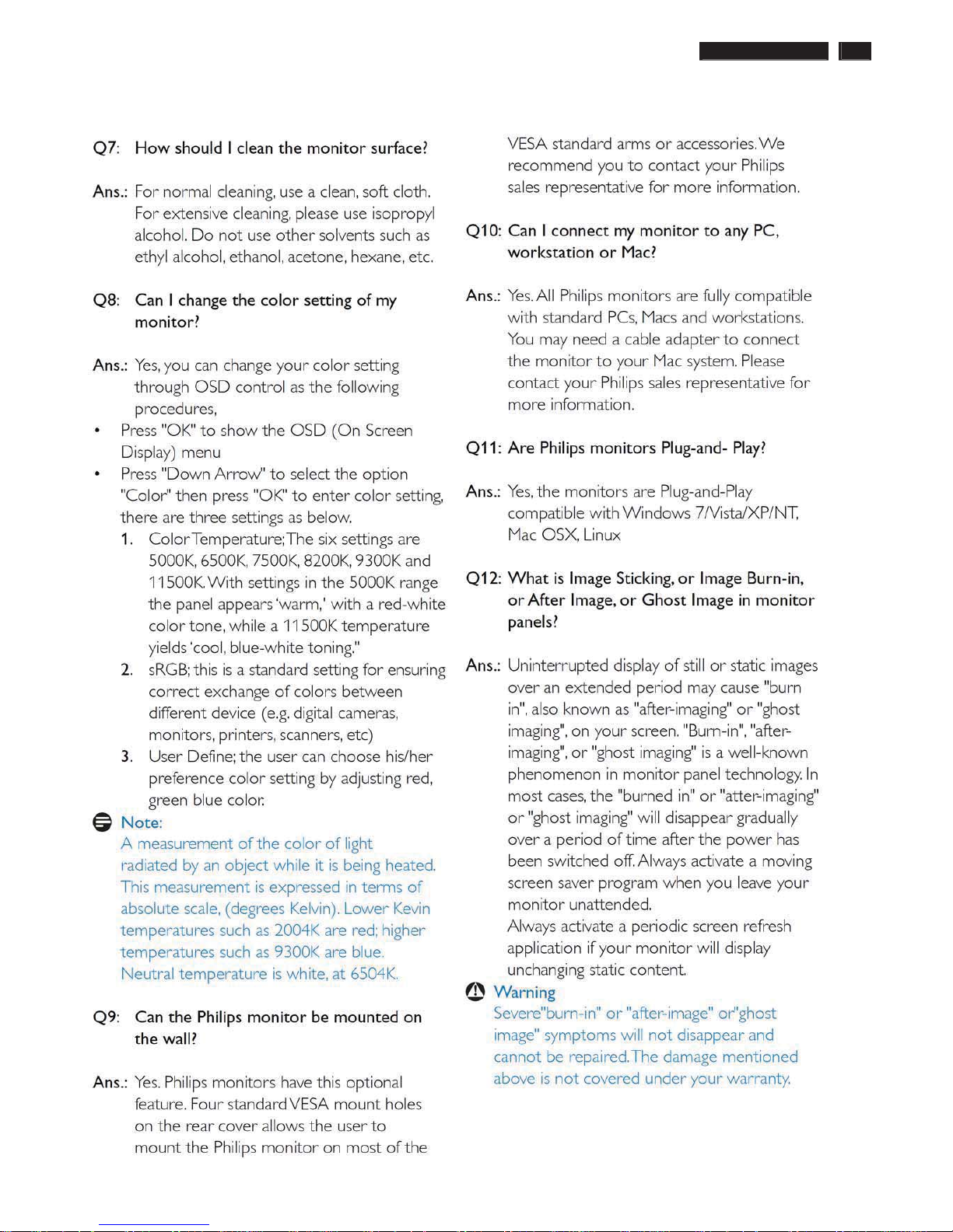
241B4LPY LCD 17
FAQs (Frequently Asked Questions)
18 241B4LPY LCD
Electrical Instructions
Electrical characteristics
1. Interface signals
1.1 D-Sub Analog
Input signal: Video, Hsync., Vsync
Video: 0.7 Vp-p, input impedance, 75 ohm @DC
Sync.: Separate sync TTL level , input impedance 2.2k ohm terminate
Hsync Positive/Negative
Vsync Positive/Negative
Composite sync TTL level, input impedance 2.2k ohm terminate
Sync on green video 0.3 Vp-p Negative (Video 0.7 Vp-p Positive)
1.2 DVI-D Digital(optional for 241S4L / 241S4LA / 241S4LC / 241B4LP )
Input signal: Single TMDS link (Three channels: RX0-/+, RX1-/+, RX2-/+)
1.3 Display port (241S4LY / 241B4LPY)
2. Interface
2.1 D-Sub Cable
Length : 1.8 M +/- 50 mm
Fix with monitor when packing, with transplant pin protective cover.
Connector type : D-Sub male with DDC2B pin assignments.
Blue connector thumb-operated jack screws
2.2 DVI Cable
The input signals are applied to the display through DVI-D cable.
Length : 1.8 M +/- 50 mm
Connector type : DVI-D male with DDC-2B pin assignments
White connector thumb-operated jackscrews
With transplant pin protective cover.
2.3 Display port cable
Length : Please refer to cable bundle summary file
Connector type : DP1.4
type A cable-connector
3. Timing requirement
3.1 Factory Preset mode definitions:
3.1.1 Perfect FOS while presenting those timings.
3.1.2 Will specify those timing in User's Manual
3.2 Preset mode definition:
3.2.1 Need to support those timings.
3.2.2 Perfect FOS after auto adjustment.
3.3 User mode
3.3.1 Can save those timing that not in Preset mode and can be showed
(not over scalar or Panel spec.)
3.3.2 It needs to reserve the 10 timings space in memory size.
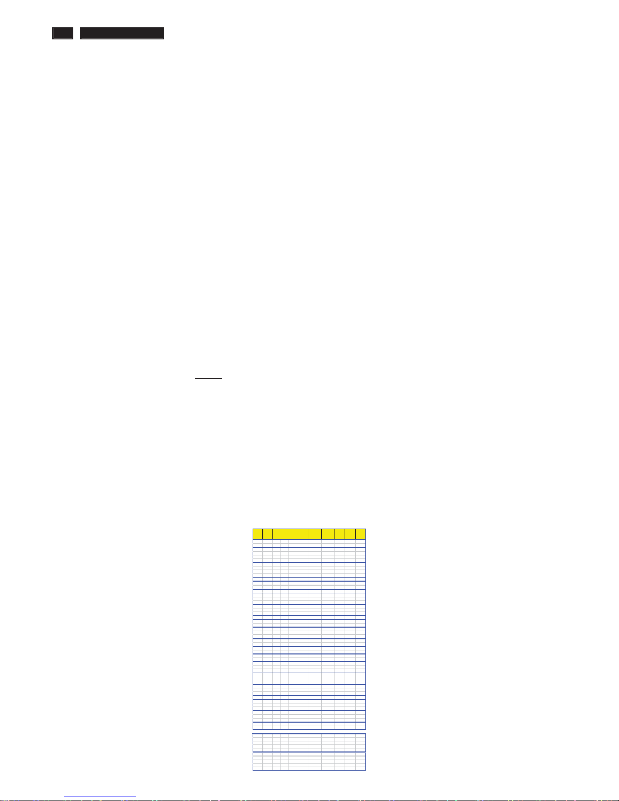
3.3.3 Factory modes and preset modes are defined in the enclosed timing table file
Support
Timing
Auto
Pixel Rate
( MHz )
Horizontal
( KHz )
Vertical
( Hz )
V_Total
( Line )
Polarity
( H / V )
1
DOS 640x350/70 25.175 31.469 70.086 449
p / n
2
DOS 720x400/70 28.322 31.469 70.087 449
n / p
3
DMT
4:3
640x480/60 25.175 31.469 59.940 525
n / n
4
MAC 640x480/67 30.240 28.571 66.667 525
n / n
5
DMT
4:3
640x480/72 31.500 37.861 72.809 520
n / n
6
DMT
4:3
640x480/75 31.500 37.500 75.000 500
n / n
7
DMT
4:3
800x600/56 36.000 35.156 56.250 625
p / p
8
DMT
4:3
800x600/60 40.000 37.879 60.317 628
p / p
9
DMT
4:3
800x600/72 50.000 48.077 72.188 666
p / p
10
DMT
4:3
800x600/75 49.500 46.875 75.000 625
p / p
11
MAC 832x624/75 57.280 49.722 74.546 667
P / p
12
CVT 960x720/60 55.750 44.671 59.721 748
n / p
13
CVT 960x720/75 71.250 56.369 74.660 755
n / p
14
1024x600/60 48.964 37.320 60.000 622
n / p
15
DMT
4:3
1024x768/60 65.000 48.363 60.004 806
n / n
16
DMT
4:3
1024x768/70 75.000 56.476 70.069 806
n / n
17
DMT
4:3
1024x768/75 78.750 60.023 75.029 800
p / p
18
CVT 1152x864/60 81.750 53.783 59.959 897
n / p
19
1152x864/70 94.499 63.851 70.012 912
p / p
20
DMT 1152x864/75 108.000 67.500 75.000 900
p / p
21
MAC 1152x870/75 100.001 68.682 74.980 916
n / n
22
SUN 1152x900/66 94.500 61.846 66.004 937
p / p
23 SUN 1152x900/76 108.000 71.809 76.149 943 p / p
24
CV
T
16:9
1280x720/60 74.250 45.000 60.000 750
p / p
25
CVT
16:9
1280x720/70 89.040 52.500 70.000 750
n / p
26
CVT
16:9
1280x720/75 95.750 56.456 74.777 755
n / p
27
DMT 1280x768/60 79.500 47.776 59.870 798
n / p
28
DMT 1280x768/75 102.250 60.289 74.893 805
n / p
29
CVT 1280x800/60 83.500 49.702 59.810 831
n / p
30
CVT 1280x800/75 106.500 62.795 74.934 838
n / p
31
DMT
4:3
1280x960/60 108.000 60.000 60.000 1000
p / p
32
CVT
4:3
1280x960/75 130.000 75.231 74.857 1005
n / p
33
DMT
5:4
1280x1024/60 108.000 63.981 60.020 1066
p / p
34
DOS
5:4
1280x1024/72 130.223 76.020 71.447 1064
p / p
35
DMT
5:4
1280x1024/75 135.000 79.976 75.025 1066
p / p
36
DMT
16:9
1360x768/60 85.500 47.712 60.015 795
p / p
37
CVT
16:9
1360x768/75 109.000 60.288 74.891 805
n / p
38
DMT
16:9
1366x768/60 85.500 47.712 59.790 798
p / p
39
DMT 1440x900/60_RB 88.750 55.469 59.901 926
p / n
40
DMT 1440x900/60 106.500 55.935 59.887 934
n / p
41
DMT 1440x900/75 136.750 70.635 74.984 942
n / p
42
DMT
4:3
1600x1200/60 162.000 75.000 60.000 1250
p / p
43
DMT
16:10
1680x1050/60_RB 119.000 64.674 59.883 1080
p / n
44
DMT
16:10
1680x1050/60 146.250 65.290 59.954 1089
n / p
45
DMT
16:10
1680x1050/75 187.000 82.306 74.892 1099
n / p
46
CVT
16:9
1920x1080/60_RB 138.500 66.587 59.934 1111
p / n
47
DM
T
16:9
1920x1080/60 148.500 67.500 60.000 1125
p / p
48
CVT
16:9
1920x1080/60 173.000 67.158 59.963 1120
n / p
49
DMT
16:10
1920x1200/60_RB 154.000 74.038 59.950 1235
p / n
50
DMT
16:10
1920x1200/60 193.250 74.556 59.885 1245
n / p
51
576P 720x576/50
27.000 31.250
50.000
625
52
576i 720x576/50
13.500 15.625
50.000
625
53
720P 1280x720/50 74.250 37.500 50.000 750
54
1080i 1920x1080/50 74.250 28.125 50.000 1125
55
1080P 1920x1080/50 148.500 56.250 50.000 1125
56
480P 720x480/60 27.000 31.468 60.000 525
57
480i 720x480/60 13.500 15.734 60.000 525
58
720P 1280x720/60 74.250 45.000 60.000 750
59
1080i 1920x1080/60 74.250 33.750 60.000 1125
241SB4 support
Resolution
Extra Supported Video Timing ( Video Timing Don’t Care Picture Quality )
60
1080P 1920x1080/60 148.500
67.500 60.000 1125
241B4LPY LCD 19
Electrical Instructions
White color adjustment
There are three factory preset white color 9300K, 6500K, sRGB.
Apply full gray64 pattern, with brightness in 100 % position and the contrast control at 50 % position.The 1931 CIE
Chromaticity (color triangle) diagram (x ,y) coordinate for the screencenter should be:
Product specification
CIE coordinates (x,y)
11500K x = 0.270 ± 0.02
y = 0.281 ± 0.02
PerfecTune II
9300K x = 0.283 ± 0.02
y = 0.297 ± 0.02
PerfecTune II
8200K x = 0.291 ± 0.02
y = 0.306 ± 0.02
PerfecTune II
7500K x = 0.298 ± 0.02
y = 0.314 ± 0.02
PerfecTune II
6500K/sRGB x = 0.313 ± 0.02
y = 0.329 ± 0.02
PerfecTune II
sRGB x = 0.313 ± 0.02
y = 0.329 ± 0.02
PerfecTune II
5000K x = 0.345 ± 0.02
y = 0.357 ± 0.02
PerfecTune II
Production alignment spec.
CIE coordinates (x,y)
11500K x = 0.270 ± 0.006
y = 0.281 ± 0.006
PerfecTune II
9300K x = 0.283 ± 0.006
y = 0.297 ± 0.006
PerfecTune II
8200K x = 0.291 ± 0.006
y = 0.306 ± 0.006
PerfecTune II
7500K x = 0.298 ± 0.006
y = 0.314 ± 0.006
PerfecTune II
6500K/sRGB x = 0.313 ± 0.006
y = 0.329 ± 0.006
PerfecTune II
sRGB x = 0.313 ± 0.006
y = 0.329 ± 0.006
PerfecTune II
5000K x = 0.345 ± 0.006
y = 0.357 ± 0.006
PerfecTune II
Quality Inspection specification:
CIE coordinates (x,y)
9300K x = 0.283 ± 0.015
y = 0.297 ± 0.015
6500K/sRGB x = 0.313 ± 0.015
y = 0.329 ± 0.015
sRGB x = 0.313 ± 0.015
y = 0.329 ± 0.015
20 241B4LPY LCD
Service tool-Hardware
PCM code 12NC
5E.L8215.001 996510019769
241B4LPY LCD 21
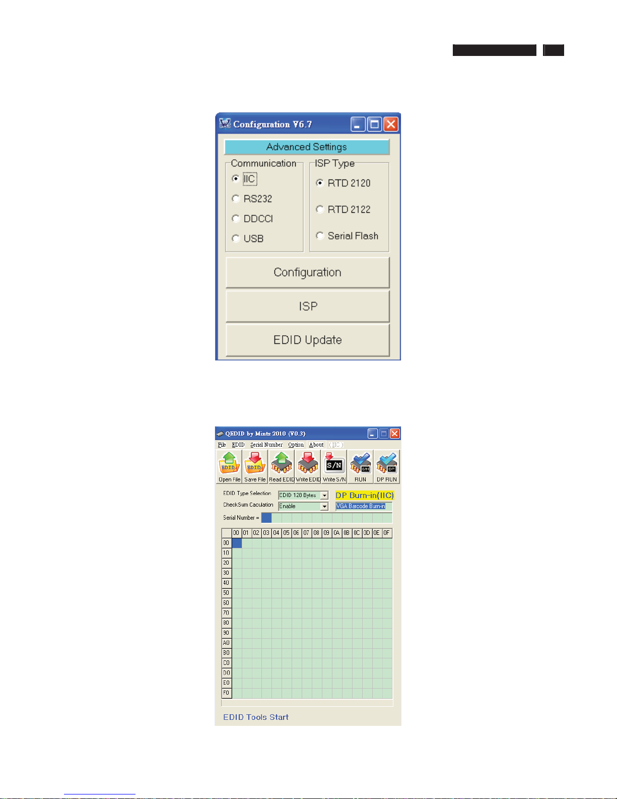
Service tool-Software
FW writing tool: RTD tool V6.7
DDC writing tool: Q-EDID-V30
22 241B4LPY LCD
DDC Instructions
DDC Data Re-programming
In case the DDC data memory IC or main EEPROM which storage all factory settings were
replaced due to a defect, the serial numbers have to be re-programmed "Analog
DDC IC, Digital DDC IC & EEPROM".
It is advised to re-soldered DDC IC and main EEPROM from the old board onto the new
board if circuit board have been replaced, in this case the DDC data does not need to be
re-programmed.
Additional information
Additional information about DDC (Display Data Channel) may be obtained from Video
Electronics Standards Association (VESA).
Extended Display Identification Data(EDID) information may be also obtained from
VESA.
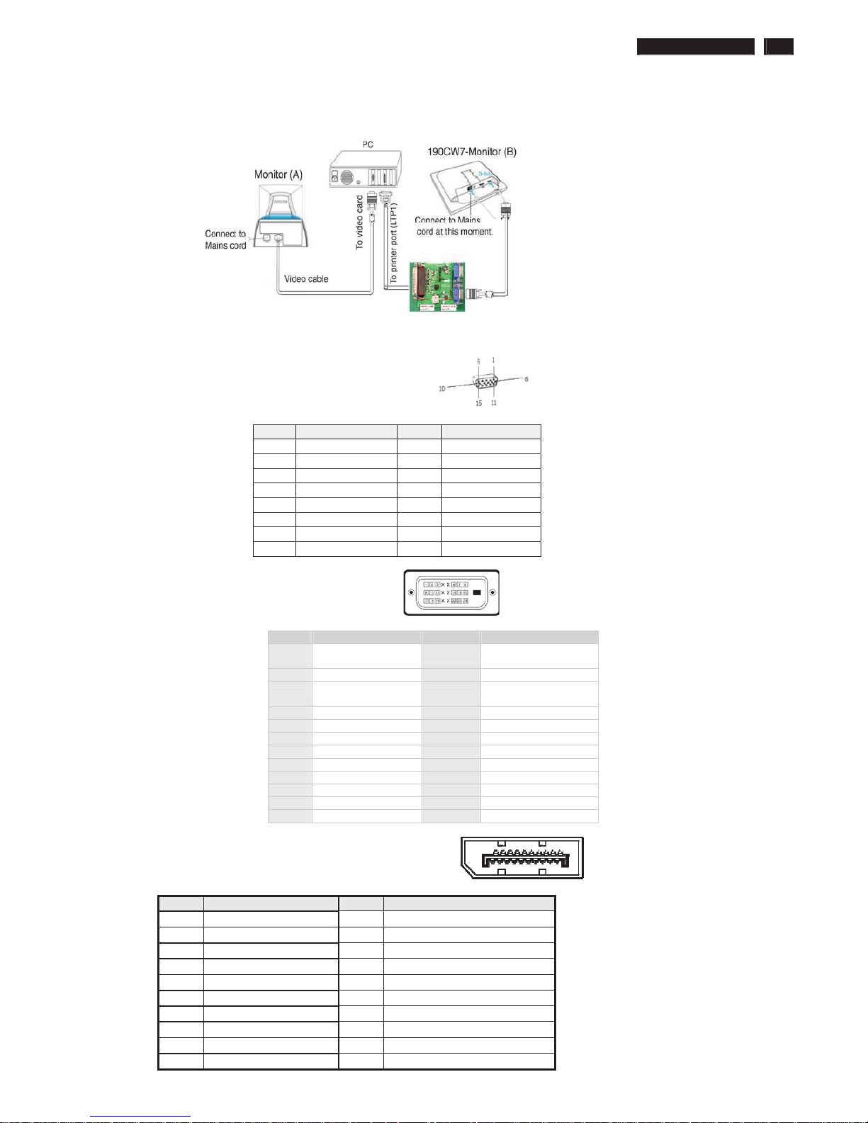
Configuration and procedure
"PI-EDID" The software is provided by IMS to upgrade the firmware of CPU.
PI-EDID Tools is for the interface between "Parallel Port of PC" and "15 pin-D-SUB
connector of Monitor".
It is a windows-based program, which cannot be run in MS-DOS.
System and equipment requirements
1. An Pentium (or above) personal computer or compatible.
2. Microsoft operation system Windows 95/98/2000/XP and Port95NT.exe.
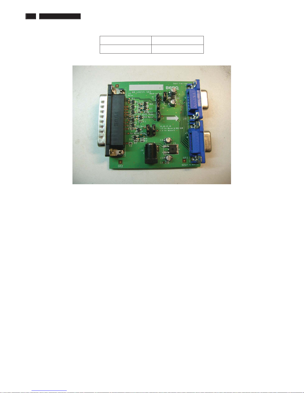
3. EDID Software "QEDID.exe"
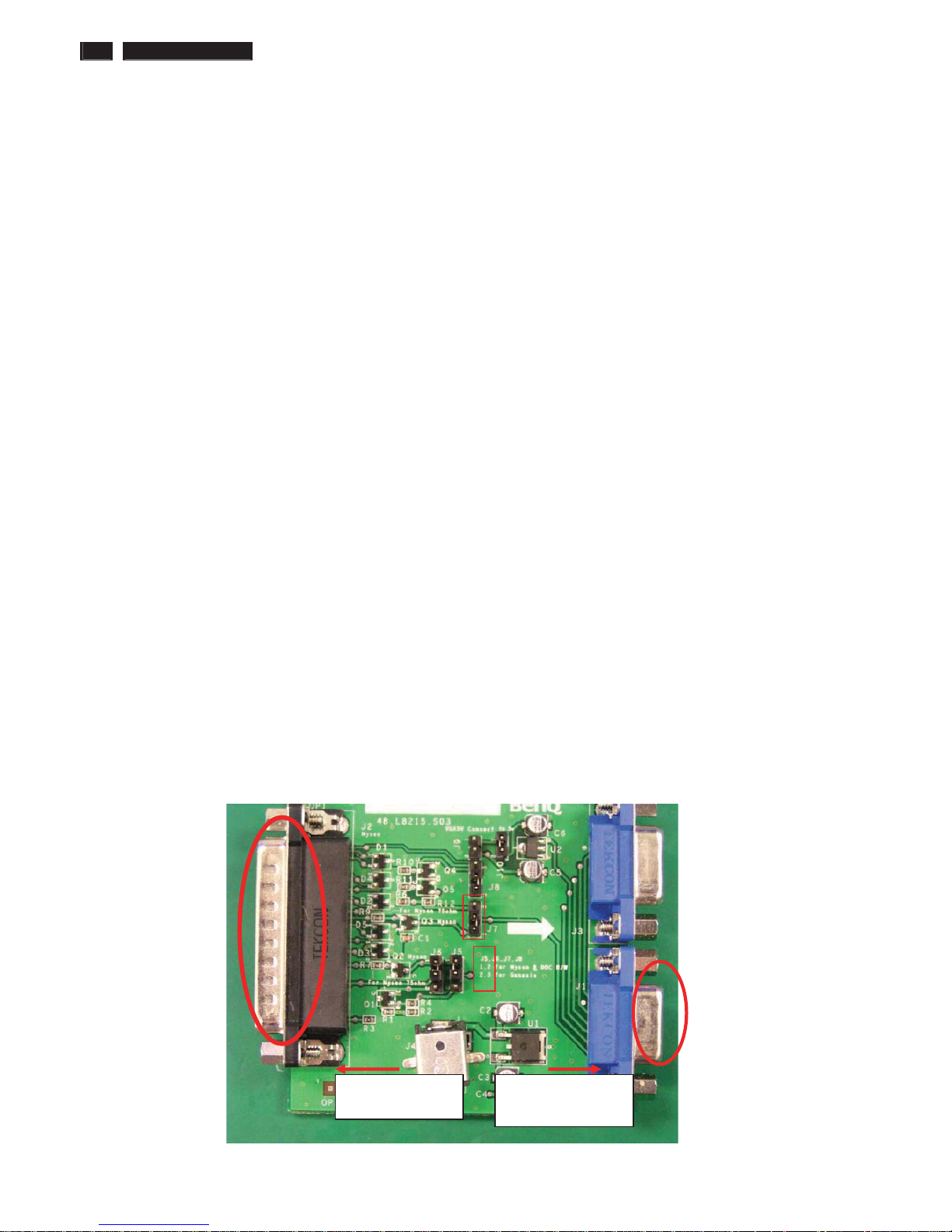
4. ISP boardas shown in Fig. 1
And I2C Board Jump wire should follow J10 (short), J9 (open), J5/J6/ (1and 2 pin short)
J7/J8 (1 and 2 pin short)
3
2
1
2
Connected to Display
Signal Cable
Connected to print
cord and PC
Fig.1
241B4LPY LCD 23
DDC Instructions
5. Connect and Mains cord to Monitor as shown in Fig.2.
Fig.2
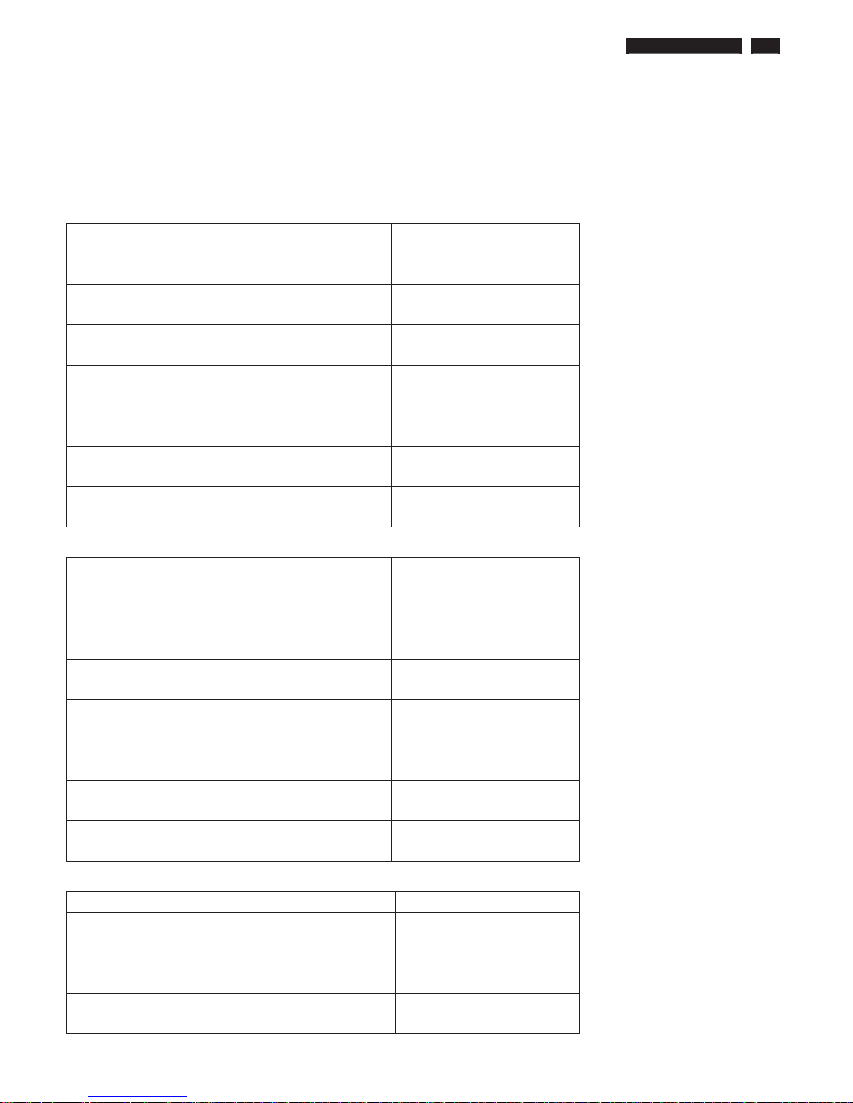
Pin assignments:
A. 15-pin D-Sub Connector
B. Input DVI Connector pin
Pin Signal Assignment Pin Signal assignment
1
TMDS RX2-
13 Floating
2 TMDS RX2+ 14 +5V Power
3 TMDS Ground 15
Self-test (Cable
detector)
4 Floating 16 Hot Plug Detect
5 Floating 17 TMDS RX06 DDC Clock 18 TMDS RX0+
7 DDC Data 19 TMDS Ground
8 Floating 20 Floating
9 TMDS RX1- 21 Floating
10 TMDS RX1+ 22 TMDS Ground
11 TMDS Ground 23 TMDS Clock+
12 Floating 24 TMDS Clock-
C. Input Display Port Connector pin
Pin Signal Assignment Pin Signal Assignment
1 Lane0 P 11
Ground
2Ground 12
Lane3 N
3 Lane0 N 13 Ground
4 Lane1 P 14 EDID WP
5Ground 15AUX_CH P
6 Lane1 N 16 Ground
7 Lane2 P 17AUX_CH N
8Ground 18
Hot Plu
g
Detect
9 Lane2 N 19
Return
10
Lane3 P
20
DP
_
PWR
PIN No. SIGNAL PIN No. SIGNAL
1 Red 9 DDC +3.3V or +5V
2 Green/ SOG 10 Logic GND
3 Blue 11 Sense (GND)
4 Sense (GND) 12 Bi-directional data
5 Cable Detect (GND) 13 H/H+V sync
6 Red GND 14 V-sync
7 Green GND 15 Data clock
8 Blue GND
ʳʳ
24 241B4LPY LCD
DDC Instructions
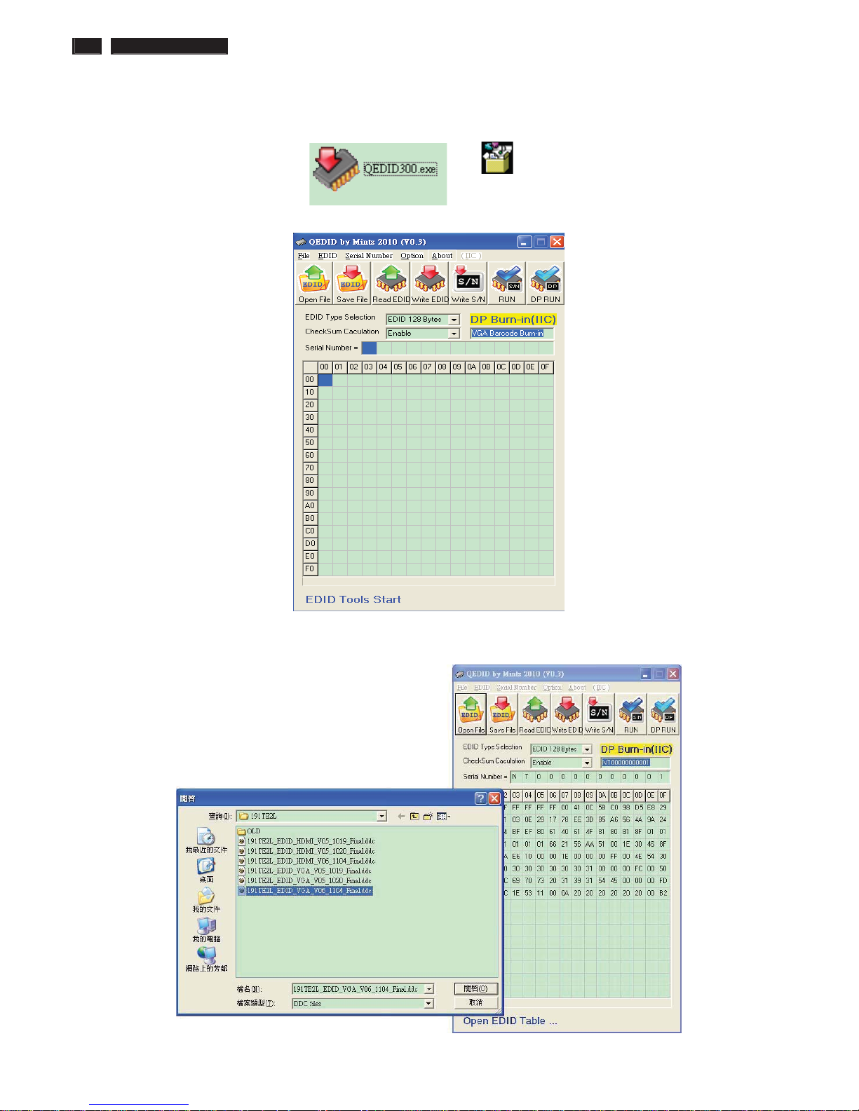
6. Setup the Philips-IMS EDID Tools program
Step 1: Open Q-EDID V030 Software into your folder as shown in Fig.3. and Fig.4.
ˤ˘˗˜˗ˆ˃˃ˁ˸˸
Fig.3
Fig.4
Step 2: Press “Open File” then chooses 241B4LPY DDC FILE
Fig.5
241B4LPY LCD 25
DDC Instructions
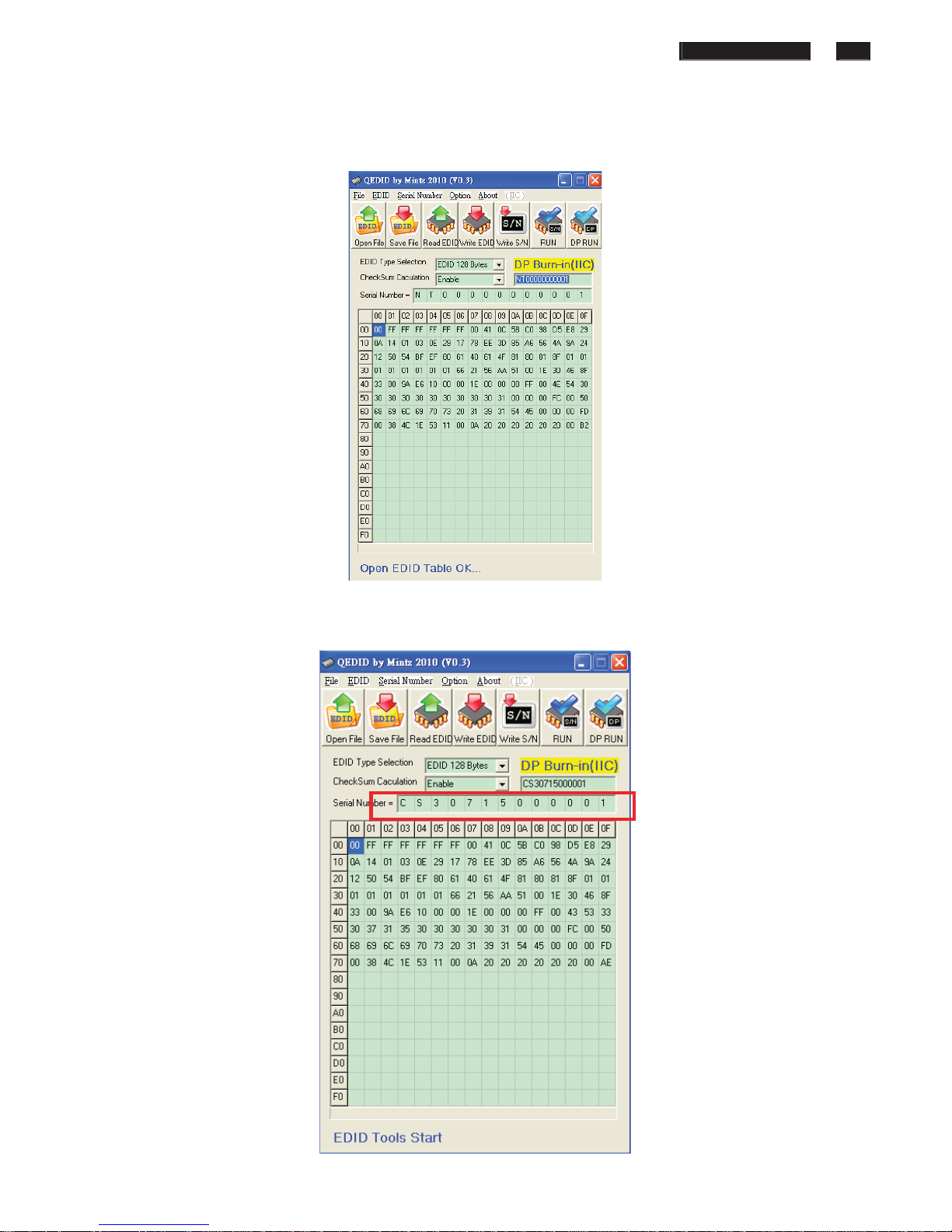
Step 3 : Load DDC file success as shown in Fig. 6 .
Fig.Step 4 : update Serial number and press enter to correct S/N number
shown as Fig.7 .
Fig.7
26 241B4LPY LCD
DDC Instructions
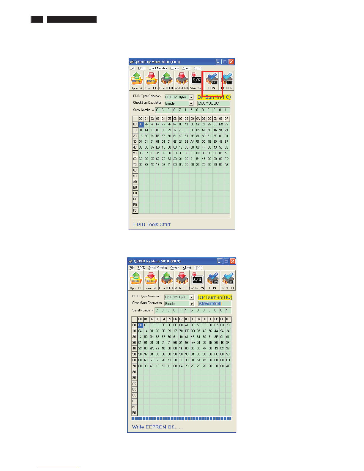
Step 5 : Press “RUN” to write EDID and serial number shown as Fig.8 .
Fig.8
Step 6 : EDID and serial number update success shown as Fig.9
Fig.9
241B4LPY LCD 27
DDC Instructions
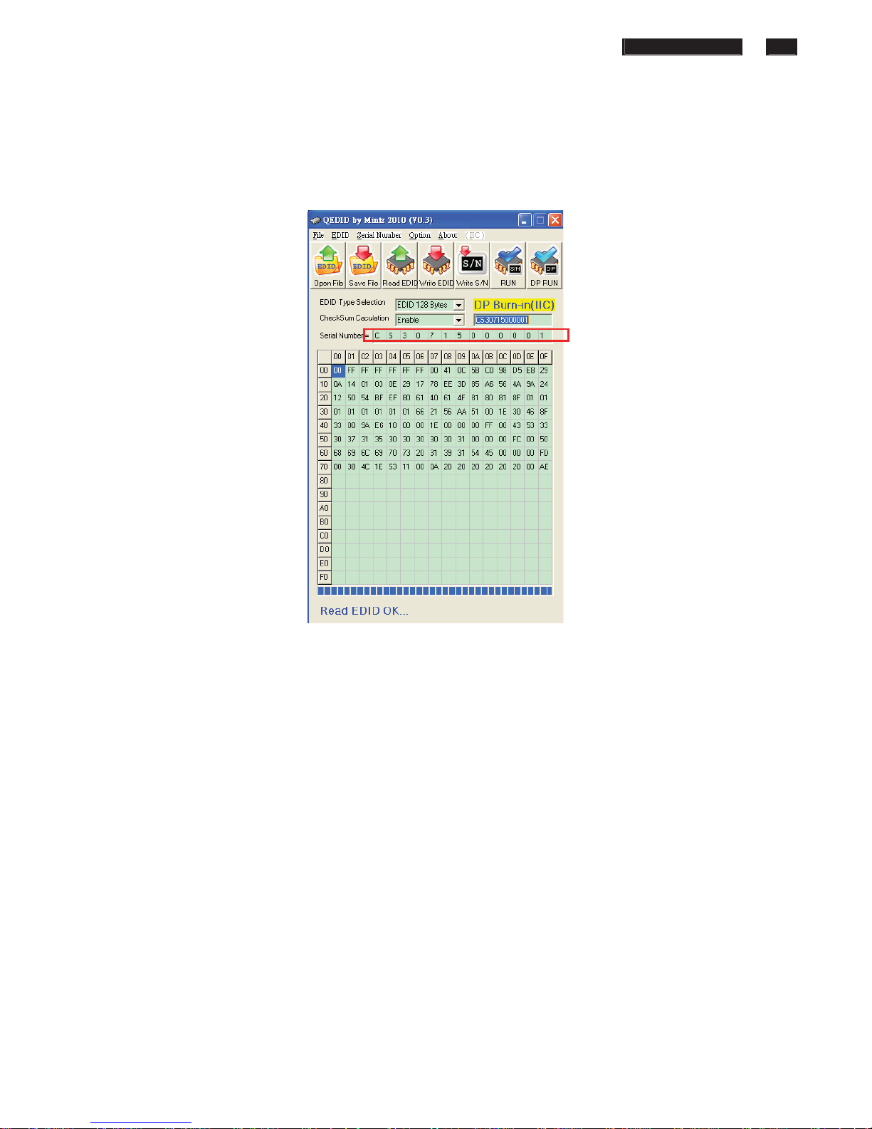
8. Press “Read EDID” to read EDID and serial number shown as Fig.10 . and check
Serial number is the same as we set.
Note: If not the same, please rewrite EDID S/N again.
Fig.10
9. Repeat Step2~7 for DVI port.
10. For DP, please use Factory function “DP EDID”. Select and enter to run this
function, if success it will show OK. shown as Fig.11
 Loading...