

Page 1
M
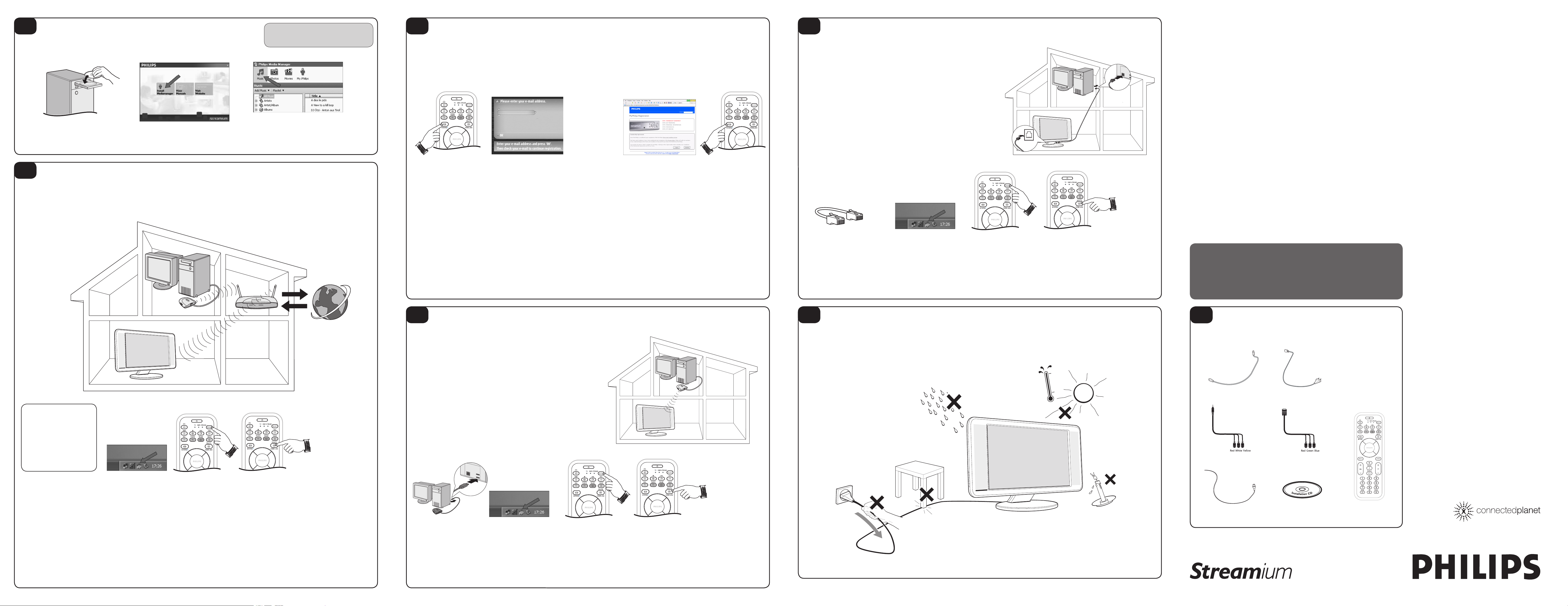
Start by installing Philips Media Manager software onto your PC
This software enables the transfer of video, music and photo files in your computer to
your LCD TV.
Install Philips Media Manager software
Note: Refer to the Streamium User Manual on “Installing
the Software” for more details on how to install the Philips
Media Manager software.
O
When the Streamium TV connects to the Internet for the first time, the Streamium TV
will prompt you to register.
Note: You need to subscribe to broadband internet connection services (min. 256 kbps) with
your local Internet Service Provider.
Connecting to the Internet for the first time
Q
For this option, you want to connect the Streamium LCD TV to your PC using a
CAT.5 shielded ethernet cable* (STP).
Note:
– Your PC must have a Ethernet connector (RJ45) available.
– Internet access is not available if the Streamium LCD TV is connected directly to PC using
the cable.
– Internet connection is available if the Streamium LCD TV is connected via cable or
wireless onto a network that has internet connection.
Installing the Streamium LCD TV to your PC using a network cable
23PF9976i
LCD TV
Place the Philips Media Manager CD in
your CD or DVD’s drive and install the
1
Philips Media Manager software.
N
For this option, you already have a wireless home computer network installed and
working properly. Refer to the user manual that came with your wireless network
adaptor/base station on installing a wireless home network.
Installing the Streamium LCD TV on a wireless home network
In the menu that appears on your
computer screen, click on ‘Install Philips
2
Media Manager’ and follow the on-screen
instructions.
Add files to the Media Manager. Only the
files that you see in the Media Manager
3
will be accessible from the Streamium TV.
Press the INTERNET button
on the remote control to
1
open the Navigation View on
your TV screen.
Note: Make sure the PC is
switched on and the Philips
Media Manager software is
installed and active.
* See the chapter ‘Enabling broadband Internet entertainment” in the User Manual for details.
With the remote control, use
the SMS TEXT-style keys* for
2
inputting your email address.
SMS TEXT-style entry can be
used to enter alphanumeric
information. In this mode, text
is entered by a method similar
to that used for entering
text messages on a cellular
telephone.
Note: You can also use the
remote control cursor Left/Right/
Up/Down keys to input your
email address.
Within a short
time, you will
3
receive an email
with instructions
on how to create
an account at
my.philips.com.
Check your email.
Double-click the website address
that is in the email. Fill in the
4
requested data to create an
account.
After registration you can access
the INTERNET service of the
Streamium TV. You can
your user account at ‘my.philips.
com’ by opening this website in
your Internet browser program or
by clicking the My.Philips button in
Philips Media Manager.
Note: Please remember your
password. You will need it if you
want to re-register.
manage
After creating a
My.Philips account,
5
press the INTERNET
button again. The
Streamium TV will
now have access to
the Internet services
of your My.Philips
account.
Use a crossover Ethernet cable*
if you want to connect the
1
Streamium TV directly to your
computer or use a straightthrough Ethernet cable* if you
want to connect the Streamium
TV to an existing computer
network.
* Cables not included.
Make sure the PC is
switched on and the
2
Philips Media Manager
software is installed
and active (an icon will
appear at the lower right
hand corner of your PC
monitor).
Switch on the Streamium
LCD TV. Press the
3
SELECT button on
the remote control
repeatedly until STREAM
indicator lights up.
Press the HOME LINK
button on the remote
4
control.
Note: Do not press the
INTERNET button at this
time.
Explore the
Home Link
5
menu on the
TV screen.
Quick Use Guide
Thank you for purchasing this Philips LCD Television set. You are now the proud owner of a
Streamium LCD TV set which promises full value to you as a customer. Before you proceed
to install the LCD TV, please follow the steps and diagrams as shown to familiarise yourself
with the correct and safe way of setting up the TV.
For details on normal LCD TV operation, making adjustments to the settings and features,
please refer to the LCD TV User Manual.
For details on using the Streamium operation, making adjustments to the settings and features,
please refer to the Streamium LCD TV User Manual.
Note: Images are for illustrations purpose only.
Note: This Quick Use Guide is designed to help you connect and install your
Streamium TV to enable you to enjoy the streaming functions that this set
offers. We strongly recommend you to read the instructions thoroughly.
WARNING: TO PREVENT FIRE OR SHOCK HAZARD DO NOT
EXPOSE THIS UNIT TO RAIN OR EXCESSIVE MOISTURE.
System Requirements
• PC-Link (Home Link)
– PC with 233 MHz Pentium, 64MB
RAM, HDD (with 50MB of free space),
CD-ROM drive and running Windows
98/98SE/2000/ME/XP or MAC OS X.
– Wireless USB adapter (USB V1.1 or
higher) or wired/wireless (WiFi 802.11b/g
compliant) home network.
• Internet services or online upgrades:
– Direct Broadband (minimal 256 kbps,
512 kbps recommended for video
streaming) Internet connection (e.g. DSL,
cable Modem or Satellite broadband) via
(wireless) base station or PC with Internet
Connection Sharing (supported from
Windows 98SE onwards).
Check the:
NETWORK NAME (SSID)
. . . . . . . . . . . . . . . . . . . . . . . . . . . . .
and
ENCRYPTION KEY
P
For this option, you do not have a wireless home computer network installed but you
want to connect the Streamium LCD TV to your PC.
Note: Internet access is not available if the Streamium LCD TV is connected directly to PC
using this method.
Installing the Streamium LCD TV without a wireless home network
R
Place your LCD TV on a solid stable surface that can support the LCD TV weight. Do
not expose the LCD TV to water or heat source (e.g. lamp, candle, radiator). Do not
obstruct the ventilation grid at the rear.
Positioning the LCD TV
A
The following accessories are provided with the Streamium LCD TV.
Listing the accessories
TV aerial cable TV power cord (two-pin)
• My.philips.com
– PC with internet access, browser and
e-mail address.
Support only the following
Media Formats
• MUSIC: MP3, MP3pro, PCM
• PICTURES: JPG (RGB), GIF, BMP
• MOVIES:
DivX 4.0/5.03
For more information go to:
MPG1, MPG2, MPG4,
www.philips.com/streamium
. . . . . . . . . . . . . . . . . . . . . . . . . . . . .
of your wireless network
Check your existing wireless
network settings and record
1
down the Wireless Network
Name (SSID) and encryption
key*. You may need to enter
this information in STEP 5 of
this procedure.
Note: Refer to the user manual
that came with your wireless
network adaptor/base station
for instructions on obtaining the
Wireless Network Name (SSID)
and encryption key.
* The encryption key is case sensitive, meaning ‘ABC’ is not the same as ‘abc”.
You must input the encryption key in the correct case.
Make sure the PC is
switched on and the
2
Philips Media Manager
software is installed
and active (an icon will
appear at the lower right
hand corner of your PC
monitor).
Switch on the
Streamium LCD TV.
3
Press the SELECT
button on the remote
control repeatedly
until STREAM
indicator lights up.
Press the HOME
LINK button on the
4
remote control.
Note: Do not press the
INTERNET button at
this time.
Select your Wireless Network
Name (SSID) and then use the
5
remote control to enter the
encryption key* you found in
step 1.
Explore the Home Link menu
on the TV screen.
Note:
– If there is only one wireless
network, it will be used and you
will not be asked to select one.
– You will not be asked to input
the encryption key if the wireless
network is not encrypted.
Install a USB Wireless
Network Adaptor (USB
1
V.1.1 or higher) to your
PC (not included).
Make sure the PC is
switched on and the
2
Philips Media Manager
software is installed
and active (an icon will
appear at the lower right
hand corner of your PC
monitor).
Switch on the
LCD TV. Press the
3
SELECT button on
the remote control
repeatedly until
STREAM indicator
lights up.
Press the HOME
LINK button on the
4
remote control.
Note: Do not press the
INTERNET button at
this time.
If asked, select from the
list of wireless network
5
names (SSID) presented
to you on the TV
screen. Select “Philips”
only if Philips adaptor
CPWUA054 is used.
Explore the Home Link
menu on the TV screen.
3139 125 33431
Mini Jack to cinch
VGA socket (DB-15) to cinch
Philips Media Manager Software Remote ControlFM radio aerial lead
Page 2

B
This LCD television has a set of controls located on the side of the cabinet for use
when the remote control is not needed.
After you have connected the power cord to the TV and plugged the cord into a
1
wall outlet, press the POWER button on the front of the TV cabinet to turn the
TV ON.
Press the VOLUME + button to increase the sound level or the VOLUME
2
– button to lower the sound level. Pressing both buttons at the same time will
display the onscreen menu. After you are in the menu, use these buttons to make
adjustments or selections.
Press the CHANNEL + or – button to select TV channels. Use these buttons to
3
make adjustments or selections in the onscreen menu.
C
Your Cable TV input into your home may be a single (75 ohm) cable or use a cable
box decoder. In either case the connection is very simple. Follow the steps below to
connect your cable signal to your new television.
LCD TV
Cable/cable box TV
Direct Cable Connections:
This connection will supply Stereo sound to the LCD TV.
Connect the open end of the round Cable Company supplied cable to the 75Ω
1
input on the bottom of the TV. Screw it down finger tight.
Cable Box with RF Inputs/Outputs Connection:
This connection will NOT supply Stereo sound to the LCD TV. The sound from the
cable box will be mono.
Connect the open end of the round Cable Company supplied cable to the cable
1
signal IN(put) plug on the back of the Cable Box.
Using a separate round coaxial cable, connect one end to the OUT(put) (TO TV)
2
plug on the back of the Cable Box.
Connect the other end of the round coaxial cable to the 75 input on the bottom
3
of the television. Screw it down finger tight.
NOTE: Be sure to set the OUTPUT CHANNEL SWITCH on the back of the cable box to
CH 3 or 4, then tune the cable box on the TV to the corresponding channel. Once tuned,
change channels at the cable box, not the television.
Cable Box with Audio/Video Outputs Connection:
This connection will supply Stereo sound to the LCD TV.
Connect the open end of the round Cable Company supplied cable to the cable
1
signal IN(put) plug on the back of the Cable Box.
Using an RCA type Video Cable, connect one end of the cable to the Video
2
(yellow) (or ANT, your cable box may be labeled differently) Out jack on the
cable box and the other end to the Video end of the composite adapter included
with the LCD TV.
Using an RCA type Audio Left and Right Cable, connect one end to the left and
3
right Audio Out L & R jacks (red & white) on the cable box. Connect the other
ends to the Audio end of the composite adapter cable included with the In jack
on the bottom of the LCD TV.
NOTE: Use the AV+ button and the Number 1 button on the LCD TV remote control to
tune to the AV1 channel for the cable box signal. Once tuned, change channels at the
cable box, not the television. Pressing the AV+ button repeatedly will scroll all the AV Input
channels, including the presently tuned channel.
1
3
1
2
Cable signal
coming from Cable
Company (Round
75Ω coaxial cable)
Cable Signal
IN from
the Cable
Company
Cable Signal
IN from
the Cable
Company
Video Cable (Yellow)
2
1
Round 75Ω
Coaxial Cable
1
Volume and Channel buttons are located
on the side of the LCD TV cabinet.
Jack Panel at Bottom of LCD TV
1
Output Channel Switch
2
Jack Panel at Bottom of LCD TV
3
Jack Panel Back of Cable
Box with A/V Outputs
Audio Cables L & R (Red, White)
Jack Panel at Bottom of LCD TV
3
1
Jack Panel
Back of Cable
Box
D
A combination antenna receives normal broadcast chan nels (VHF 2-13 and UHF 14-
69). Your connection is easy because there is only one 75
the back of your LCD TV, and that’ s where the antenna goes. If your antenna has a
round cable (75 ohm) on the end, then you’re ready to connect it to the LCD TV.
If your antenna has flat, twin-lead wire (300 ohm), you first need to attach the
1
antenna wires to the screws on a 300- to 75-ohm adapter.
Push the round end of the adapter (or antenna) onto the 75 (ohm) plug on the
2
bottom of the LCD TV. If the round end of the antenna wire is threaded, screw it
down finger tight.
E
The audio/video input jacks on the bottom panel of the TV are for direct picture and
sound connections between the TV and a VCR (or similar device) that has audio/video
output jacks.
Connect the AV1 In(put) cable to one end of an RCA type VIDEO (yellow) cable
1
to the supplied Audio/Video adapter. Connect the other end of the Adapter to
the AV1 in jack on the bottom of the TV.
Connect the AV1 In(put) cable to one end of the RCA type AUDIO (red and
2
white) cables to the supplied Audio/Video adapter.
Turn the VCR or accessory device and the LCD TV ON.
Antenna Connection
Ω (ohm) antenna plug on
AV1 Inputs
3
Press the AV+ button and the number 1 button on the remote control to select
4
the AV1 channel for the accessory device. AV1 will appear in the upper left
corner on the TV screen when tuned properly. You can also press and hold the
AV+ button to toggle through the various channels until AV1 appears on the
screen.
With the VCR (or accessory device) ON and a prerecorded tape (CD, DVD,
5
etc.) inserted, press the PLAY button to view the tape on the television.
F
Component Video inputs provide the highest possible color and picture resolution in
the playback of digital signal source material, such as with DVD players.
Connect the Component (Y , Pb, Pr) Video OUT jacks from the DVD player (or
1
similar device) to the COMP(onent) VIDEO Input (Y green, Pb blue, Pr red) jacks
on the bottom of the TV. When using the Component Video Inputs, it is best not
to connect a signal to the AV1 in Video Jack.
Connect the red and white AUDIO CABLES to the Audio (left and right) output
2
jacks on the rear of the accessory device to the Audio Adapter supplied (L and
R). Connect the adapter into the AV1 In Input Jacks on the TV.
Turn the TV and the DVD (or digital accessory device) ON.
Component inputs (CVI)
3
Press the AV+ on the remote control repeatedly until CVI appear in the upper
4
left corner of the TV screen.
Insert a DVD disc into the DVD player and press the PLAY π button on the
5
DVD Player.
Note: – When using additional accessories, only one external source will be audible, as
there is only one AV1 Input jack.
– The CVI input is for non-progressive input. For progressive input, please follow the HD
connection.
G
If you are using a High Definition receiver that can transmit high definition
programming, the TV can accept those signals through the HD Inputs located on the
bottom of the LCD TV.
For Analog Connection, use Component Video cables to connect the
1
Component (Y, Pb, Pr) Video Out jacks of the HD Receiver (or similar device)
to the VGA adapter (supplied with the LCD TV). Connect the other end of the
adapter to the VGA Input jacks on the bottom of the LCD TV.
Connect the red and white audio adapter to RCA type Audio Cables. Connect
2
the audio adapter to the PC/HD Audio Input jack on the bottom of the LCD TV.
Turn the TV and the HD Receiver ON.
HD (High Definition) inputs
3
Press the HD Mode button to set the TV into the HD Mode and tune to the HD
4
signal.
Note: The Audio/Video cables needed for this connection are not supplied with your TV.
Please contact your dealer or Philips at 1-888-PHILIPS (744-5477) for information about
purchasing the needed cables.
Outdoor or
Indoor Antenna
(Combination
VHF/UHF). The
combination
antenna receives
normal broadcast
channels 2-13 (VHF)
and 14-69 (UHF).
Twin Lead
Wire
Round 75Ω
Coaxial Cable
from Antenna
4
1
300 to 75-ohm
Adapter
Tune to AV1
channel
Audio IN
(red/white)
2
Jack Panel at Bottom of LCD TV
Jack Panel at Bottom of LCD TV
Video IN
(yellow)
5
2
VCR (or accessory
device) equipped
with video and
Audio output jacks
4
Back of VCR
(or accessory
device)
1
3
1
4
Audio cables
(red/white)
4
3
Accessory device equipped
with component Video outputs.
Helpful Hint: The description for the component video connectors may differ depending on the DVD
player or accessory digital source equipment used (for example, Y, Pb, Pr; Y, B-Y, R-Y ; Y, Cr, Cb).
Refer to your DVD or digital accessory owner’s manual for definitions and connection details.
Jack Panel at Bottom of LCD TV
4
Audio
cables
3
Jack Panel at Bottom of LCD TV
2
Component Video cables
(green, blue, red)
The CVI connection will
be dominate over the AV1
in Video Input. When a
Component Video Device
is connected as described, it
5
is best not to have a video
signal connected to the AV1
in Video Input jack.
1
Component
Video cables
(green, blue, red)
Rear of HD Receiver
(Illustration is for reference
only. Your HD Receiver
jack panel may be labeled
HD Receiver
equipped with
component
Video outputs
differently
2
H
This LCD TV can be used as a PC Monitor. Your computer will have to be equipped
with a VGA type video output and VGA cable.
Connect one end of the VGA Video cable to the Monitor (video) output on the
1
computer to the PC Input (VGA) jack on the bottom of the LCD TV. You can
use the HDMI cable if your computer has HDMI capability
Connect the AUDIO PC/HD cable of the TV to the Audio output on the PC.
PC (monitor) inputs
2
Turn the LCD TV and the Computer ON.
3
Press the VGA button to set the TV into the HD Mode and tune to the
4
computer’s signal.
Note: For the display resolutions available to your LCD TV, refer to the Operating Instruction
Manual
Please contact your dealer or Philips at 1-888-PHILIPS (744-5477) for information about
purchasing the needed cables.
I
The Rear jacks allow for extra accessory device connections for items such as cameras
or gaming stations.
Connect the VIDEO (yellow) adapter cable to the VIDEO IN jack on the rear
1
of the TV. Connect the other end of the VIDEO (yellow) cable to an RCA type
VIDEO Cable. Connect that cable to the VIDEO OUT jack on the back of the
accessory device being used. Note: An S-Video cable can be used in place of the
yellow Video cable if your device is equiped with an S-Video Output. S-Video
provides better video playback.
Connect the AUDIO (red and white) adapter cable to an RCA type Audio Cable.
2
Connect the other ends of the AUDIO (red and white) cables to the AUDIO
(left and right) OUT jacks on the rear of the accessory device being used.
Turn the accessory device and the LCD TV ON.
AV3 inputs
3
Press the AV+ button and the number 3 button on the remote control to select
4
the AV3 channel for the accessory device. REAR will appear in the upper left
corner on the TV screen when tuned properly.
With the accessory device ON, press the PLAY button to activate the playback
5
on the television.
J
The Headphone jack can be used to connect to a headphone. If connected to a
headphone, there will be no sound from the TV speakers. The sound willcome from
the audio system of the headphone.
Connect Headphone jack ocated on the right rear of the LCD TV to your
1
headphone set.
Turn the TV and headphone ON. TV sound can be heard through the
2
headphone.
K
To load the supplied batteries into the remote:
Remove the battery compartment door on the back of the remote.
Headphone output
Remote control batteries
1
After removing the plastic isolation sheet from the battery, place the battery (3V)
2
in the remote. Be sure the (+) and (–) ends of the batteries line up correctly (the
inside of the case is marked).
Reattach the battery compartment door.
3
4
4
Lithium
battery (3V)
Battery
Compartment
Door
Jack Panel at Bottom of LCD TV
PC
Jack Panel at rear
of LCD TV
Accessory device
(camera, DVD,
VCR, etc.)
Jack Panel at rear
of LCD TV
3
1
1
5
Note: an S-Video cable can be used in
place of the yellow Video cable if desired.
Headphone cable
1
Remote Control
(shown from the bottom)
Note: The plastic isolation sheet must be
removed for the remote control to function.
VGA cable
OR
HDMI cable
S-Video
cable
2
Headphone
1
1
Audio cable
Video cable
Audio cable
Accessory device
jack panel
2
Be sure to point the remote at
the remote sensor window on
the front of the television when
using the remote control to
operate the television
2
L
Remote control buttons
Streamium functions
1
2
3
4
5
6
7
8
9
Power button
– Power Streamium LCD TV off (to standby).
1
– Power on the Streamium LCD TV with the INTERNET or HOME LINK button.
Playback control buttons
Playback (Play/Pause/Previous/Next) functions for multimedia content.
2
Coloured menu buttons
For selecting or activating the color-coded option from the on-screen menu.
3
Internet source button
– Selects the Internet as your sorce of multimedia content.
4
– Requires a broadband Internet access of minimum 256 kbps, higher recommended.
Cursor buttons (Left, Right, Up, Down)
Press these buttons to highlight, select, and adjust items on the TV’s onscreen menu.
5
Menu button
Accesses the Streamium menu settings.
6
Volume (+) or (–) buttons
Increase or decrease volume.
7
Shuffle button (Home Link only)
Selects the Shuffle mode.
8
Number/Text buttons
For entering numbers and SMS-style TEXT.
9
Select mode buttons
10
11
12
13
Allows you to select TV, DMR or STREAM mode.
Home Link source button
Selects the Home Link as your sorce of multimedia content.
OK/Play button
Confirms selection and start playing content.
Repeat button (Home Link only)
Selects the repeat mode.
10
11
12
13
IMPORTANT
Press the SELECT button repeatedly
on the remote control until the
indicator is lighted up at STREAM to
allow you to access the Streamium
functions.
TV functions
1
2
3
4
5
6
7
8
9
10
11
12
Power button
Power Streamium LCD TV ON and OFF.
1
AV+ button
Press button followed by the Number 1 or 2. Number 1 allows you to select AV1
2
(CVI), Number 2 to select to select Rear channel.
– Sleeptimer button
Set the TV to automatically turn itself OFF at a given amount of time.
3
– Surf button
Selects previously viewed channels. You canplace up to 10 channels in memory.
Then by pressing the SURF button you can quickly view the select channels.
– PIP (Picture-in-Picture) buttons
Function not available.
Mode buttons
Press TV/PC/Radio/HD button to enter TV, PC, Radio or HD mode directly.
4
Format button
Press to toggle the different screen format options.
5
Cursor buttons (Left, Right, Up, Down)
Press these buttons to highlight, select, and adjust items on the TV’s onscreen menu.
6
Menu button
Press to enter and also exit On-Screen menu.
7
Mute button
Press to turn the TVsound OFF . Press again to return the sound to its previous level.
8
Volume (+) or (–) buttons
Increase or decrease volume.
9
Auto Picture buttons
10
11
12
13
14
15
16
17
Allows you to acess and select the different types of pictures setting.
Number buttons
Press the number buttons for direct access to the TV channels. For a 2-digit channel,
enter the 2nd digit before the dash disappears. For a 3-digit channel, enter the first
digit followed the next 2 digits.
Status button
Press to see the current channel number on the TV screen. Also press to exit the
menu.
Select mode buttons
Allows you to select TV, DMR or STREAM mode.
Program List button
Press to display a list of channel numbers. Each channel will appear as a selectable
menu item. When in Accessory mode, it confirms selections or adjustments in
Accessory device.
Auto Sound button
Allows you to acess and select the different types of sound setting.
Channel (+) or (–) buttons
Press to access the next or previous channel.
CC button
Press to select Closed Captioning options within the menu.
13
14
15
16
17
IMPORTANT
Press the SELECT button repeatedly
on the remote control until the
indicator is lighted up at TV to allow
you to access the LCD TV functions.
 Loading...