

Page 1
Quick Use and Hookup Guide
CONTENTS
100x100mm
3
1
2
100x100mm
EnglishFrançaisEspãnolPortuguês
INSTALLING LCD TV ON THE WALL . . 1
TV CHANNEL INSTALLATION . . . . . . . . 2
PRESENTATION OF THE LCD TV.. . . . . 2
ACCESSORIES. . . . . . . . . . . . . . . . . . . . 3
BATTERY INSTALLATION . . . . . . . . . . . . 3
REMOTE CONTROL OPER ATION . . . . . . 3
ANTENNA TV . . . . . . . . . . . . . . . . . . 4
BASIC CABLE TV CONNECTION . . . . . . . . 4
TUNER MODE CONTROL . . . . . . . . . . . 5
AUTO PROGRAM (SETTING UP
CHANNELS . . . . . . . . . . . . . . . . . . . . . 5
CABLE BOX (WITH RF IN /OUTPUTS) . . 6
CABLE BOX (WITH AUDIO /VIDEO
OUTPUTS) . . . . . . . . . . . . . . . . . . . . . 6
VCR, DVD PLAYER, OR OTHER DE VICES
WITH RCA CONNECTORS . . . . . . . . . 7
DVD PLAYER OR OTHER VIDEO DEVICES
WITH COMPONENT VIDEO
CONNECTORS . . . . . . . . . . . . . . . . . . 7
DIGITAL TV RECEIVER, OR A DIGITAL
SATELLITE RECEIVER WITH HD (HIGH
DEFINITION) OUTPUT . . . . . . . . . . . . . 8
PC (MONITOR) CONNECTIONS . . . . . 8
DIGITAL SATELLITE RECEIVER WITH DVI
CONNECTOR . . . . . . . . . . . . . . . . . . . 9
AV OUTPUT . . . . . . . . . . . . . . . . . . .10
IMPORTANT
NOTE: This quick setup guide is used with several
different LCD TV models. Not all features (and drawings)
discussed in this manual will necessarily match those
found with your LCD TV set. This is normal and does not
require that you contact your dealer or request service.
WARNING: TO PREVENT FIRE OR SHOCK HAZARD
DO NOT EXPOSE THIS UNIT TO RAIN OR EXCESSIVE.
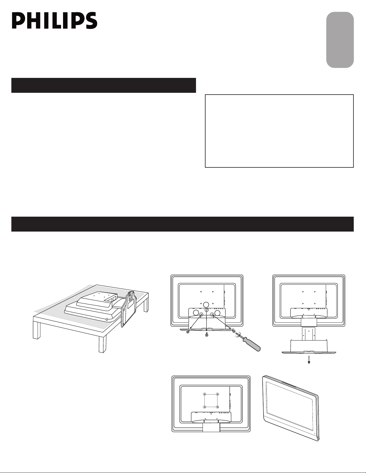
INSTALLING LCD TV ON THE WALL
Before you can install your LCD TV on the wall, you must fi rst remove the base using the steps below:
Place the set facing down on a fl at surface with
1
a protective sheet or cloth beneath the TV.
Remove 3 screws from base.
2
Grasp the base and pull it out.
The 4 hole on the rear side of your LCD TV comply
with Vesa standard.
When installing the LCD TV on the wall, please consult
a professional technician for proper installing.
The manufacture accepts no liability for installations not
performed by professional technician.
1
3138 155 24062
Page 2
TV CHANNEL INSTALLATION
AU T O ST O RE
PL E AS E W AI T
PR O G. F O UN D 0
CH A NN E L 3
IN S TA L L
LA N GU A G E
TU N ER M O DE
AU T O PR O GR A M
CH A NN E L ED I T
FA C TO R Y RE S E T
IN S TA L L
LA N GU A G E
TU N ER M O DE
AU T O PR O GR A M
CH A NN E L ED I T
FA C TO R Y RE S E T
ST A RT ?
MA N UA L F IN E T UN E
MA N UA L F IN E T UN E
MA I N CO N TR O LS
PI C TU R E
AU D IO
FE A TU R E S
IN S TA L L
LA N GU A G E
TU N ER M O DE
AU T O PR O GR A M
CH A NN E L ED I T
FA C TO R Y RE S ET
MA N UA L F IN E T UN E
AN T EN N A
CA B LE
AU T O
1
3
4
5
7
3
4
6
2
5
1
3
2
-
Vo lu m e
+
- C h a n n e l +
M e n u
1
4
Immediately after unpacking and plugging in your new television, run the auto program function
to set up the TV for the broadcast or cable channels available in your area. If you do not run the
auto program function to set up the channels , your television may not operate properly.
Please follow these steps to install TV channels:
Select a TV source via AV+ button on your remote control.
1
Press the CURSOR RIGHT button to confi rm.
Press MENU button on your remote control to open the onscreen menu.
2
Press CURSOR DOWN to move to INSTALL, press CURSOR RIGHT on your
3
remote control to enter INSTALL.
Press CURSOR DOWN to select TUNER MODE, press CURSOR RIGHT on your
4
remote control to select CABLE, ANTENNA or AUTO mode.
CABLE IF you have a cable input
ANTENNA IF you have an antenna input
AUTO IF you are not sure what kind of TV signal input you have
(Cable or Antenna)
Press CURSOR RIGHT to confi rm, then press MENU to return previous layer.
5
Press CURSOR DOWN to move to AUTO PROGRAM.
6
Press CURSOR RIGHT to start auto install the TV Channels.
7
For more detailed explanation of AUTO PROGRAM, please refer to
AUTO PROGRAM section on page 5.
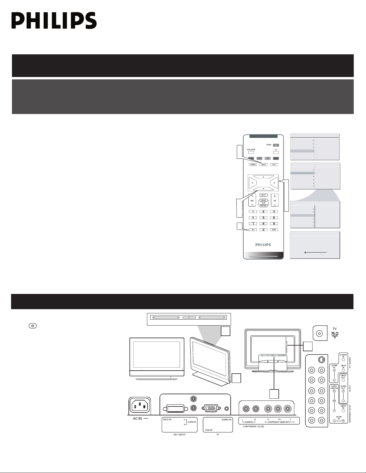
PRESENTATION OF THE LCD TV
Television Keys
1
• : To switch the TV on or off.
•VOLUME + / - : To adjust sound level.
•CHANNEL + / - : To select programs.
•MENU : to access or close onscreen menu.
Power button, LED light and infrared
2
3
4
sensor
Aim remote control at infrared sensors to
activate TV controls.
Rear connectors
Located at the rear of the set.
Bottom connectors
Located at the bottom of the set.
2
Page 3
ACCESSORIES
Owner`s Manual & Quick Use and Hookup Guide
Tuner L-Adapter
Warranty Card
Power cable
W
a
r
r
a
n
t
y
C
a
r
d
Wa
r
r
an
t
y
C
a
r
d
Tuner L-Adapter
Warranty Card
W
a
r
r
a
n
t
y
C
a
r
d
W
a
r
r
an
t
y
C
a
r
d
BATTERY INSTALLATION
When you unpack this unit, make sure it includes the
following:
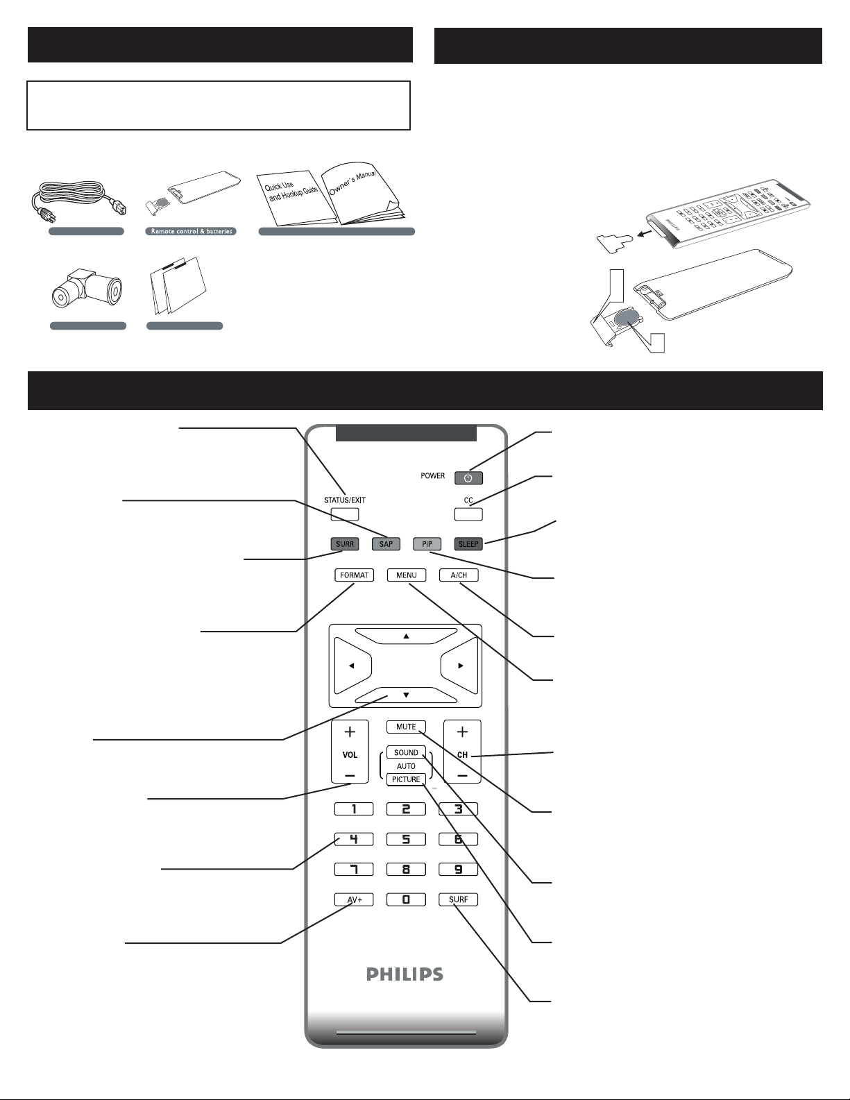
REMOTE CONTROL OPERATION
Status/Exit Button-
Press to see the current channel number on the
TV screen. Also press to clear the TV menu
after control adjustments.
SAP button
Press to select a sound mode if available with
the TV programming:Mono, Stereo, or SAP.
Incredible Surround button-
Adds greater depth and dimension to TV
sound.
Select from Incredible Surround or OFF.
Remove the battery compartment lid on
1
the bottom of the remote control.
Place lithium cell in the remote control.
2
Be sure the (+) and (-) ends of the
batteries line up as marked inside the
battery (CR2025) compartment.
Reattach the battery
compartment lid.
3
Power button
Press to turn the LCD TV on or off.
CC button
Press the CC button to select CC on or CC off.
Sleep button
Press to set the LCD TV to turn itself off within a
certain time.
PIP button
Press repeatedly to change the size of PIP window
in PC mode.
Picture Format button
Press the FORMAT button repeatedly to toggle
among the six screen format sizes; WIDESCRE EN,
4: 3, ZOOM 14: 9, ZO OM 16:9, SU BTITLE ZOOM
or S UPERWIDE .
Cursor Buttons (Left, Right, Up,
Down)-
Press these buttons to highlight, select, and
adjust items on the TV’s on screen menu.
Volume button
Press to increase or decrease the sound level.
Number buttons
Press the number buttons for direct access to
the TV channels. For a 3-digit channel, enter
the first digit followed the next 2 digits.
AV+ button
Press to select the video input source: PC, DVI, TV,
AV1, AV2, Component, S-Video, HD.
3
A/CH Button
Press to go to previously selected channel.
Menu button
Press to activate onscreen menu, back to
previous level inside the onscreen menu, or
press to exit the onscreen menu.
Channel button
Press to adjust the channel up or down.
Mute button
Press to eliminate or restore the LCD TV sound.
Mute will appear on the screen when the sound is
muted.
Auto Sound button
Press repeatedly to select among the 4 settings;
Personal, Voice, Music, or Theatre.
Auto Picture button
Press repeatedly to select either Personal, Rich,
Natural, Soft, or Multimedia picture setting.
Surf Button
Press to select previously viewed channels. You
can place up to 8 channels in memory. Then by
pressing the SURF button you ca
select channels.
n quickly view the
Page 4

ANTENNA TV
Outdoor or Indoor Antenna
(Combination VHF/UHF)
Twin-lead wire
to 300-75Ω adpter
or
Antenna
with 75Ω
cable
1
2
Wall outlet
3
The Cable TV singal
from Cable Company
75Ω coaxial cable
Rear Jack panel of Television
Wall outlet
2
1
A combination antenna receives normal broadcast channels (VHF 2–13 and UHF 14–69). Your connection is easy because there is only
one 75 Ω (ohm) antenna jack on the side of your TV, and that’s where the antenna goes.
If your antenna has a round cable (75 ohm) on the end, then
1
you’re ready to connect it to the LCD TV. If your antenna
has fl at, twin-lead wire (300 ohm), you fi rst need to attach
the antenna wires to the screws on a 300- to 75-ohm
adapter(not supplied).
Connect the antenna (or adapter) to one end of the
2
supplied L-Adapter as shown, and connect the other end of
the L-Adapter to the TV jack on the side of the LCD TV.
Plug the power cable into AC inlet on LCD TV set. Plug the
3
power cable into an outlet and switch TV set on.
Run the AUTO PROGR AM function to set up the TV for the
4
broadcast or cable channels available in your area. If you do
not run the auto program function to set up the channels ,
your television may not operate properly.
• Remember, an antenna or cable TV signal must fi rst be connected to
your LCD TV.
• Please make sure that you have selected the TV mode with AV+ key
on your remote control, before installing TV channels.
HELPFUL HINT
BASIC CABLE TV CONNECTION
Your Cable TV input into your home may be a single (75 ohm) cable or use a cable box decoder. In either case the connection is very
simple. Follow the steps below to connect your cable signal to your new television.
Direct cable connections:
Connect the Cable TV signal to one end of the supplied
1
L-Adapter as shown, and connect the other end of the
adapter to the TV jack on the LCD TV.
Plug the power cable into AC inlet on LCD TV set. Plug the
2
power cable into an outlet and switch TV set on.
Run the AUTO PROGR AM function to set up the TV for the
3
broadcast or cable channels available in your area. If you do
not run the auto program function to set up the channels ,
your television may not operate properly.
• Remember, an antenna or cable TV signal must fi rst be connected to
your LCD TV.
• Please make sure that you have selected the TV mode with AV+ key
on your remote control, before installing TV channels.
HELPFUL HINT
4
Page 5

TUNER MODE CONTROL
AU T O S TO R E
PL E A SE W A I T
PR O G .F O U ND 0
CH A N NE L 3
IN S T AL L
LA N G UA G E
TU N E R MO D E
AU T O P RO G R AM
CH A N NE L E D IT
FA C T OR Y R E SE T
IN S T AL L
LA N G UA G E
TU N E R MO D E
AU T O P RO G R AM
CH A N NE L E D IT
FA C T OR Y R E SE T
ST A R T?
MA N U AL F I N E TU N E
MA N U AL F I N E TU N E
MA I N CO N T R OL S
PI C T UR E
AU D I O
FE A T UR E S
IN S T AL L
LA N G UA G E
TU N E R M O D E
AU T O PR O G R AM
CH A N NE L E D IT
FA C T OR Y R E SE T
MA N U AL F I N E T U N E
AN T E NN A
CA B L E
AU T O
3
5
2
4
1
6
MA I N C O N TR O LS
PI C TU R E
AU D IO
FE A TU R E S
IN S TA L L
LA N GU A G E
TU N ER M O DE
AU T O P R O GR A M
CH A NN E L ED I T
FA C TO R Y RE S ET
MA N UA L F IN E TU N E
IN S TA L L
LA N GU A G E
TU N ER M O DE
AU T O P R O GR A M
CH A NN E L ED I T
FA C TO R Y RE S ET
MA N UA L F IN E TU N E
1
6
2
4
5
AN T EN N A
CA B LE
AU T O
The Tuner Mode allows you to change the LCD TV’s signal input to Cable or Air
(antenna). It’s important for the LCD TV to know if you want to receive channels from a cable TV signal or an antenna signal.
Press the MENU button to see the onscreen menu.
1
Press the CURSOR DOWN button to highlight the INSTALL menu.
2
Press the CURSOR RIGHT button to enter the INSTALL menu.
3
Press the CURSOR DOWN button to highlight the TUNER MODE menu,
4
then press CURSOR RIGHT to confi rm.
Press the CURSOR DOWN button to select CABLE, ANTENNA
5
or AUTO, then press CURSOR RIGHT to confi rm.
Press the MENU button repeatedly to clear the menu from the screen.
6
• When CABLE is selected, channels 2-125 are available.
• When ANTENNA is selected, channels 2-69 are available.
• When AUTO is selected, your LCD TV will search automatically for antenna
or cable channels.
• Immediately after unpacking and plugging in your new television, run the AUTO
PROGRAM
available in your area. If you do not run the auto program function to set up the
channels, your television may not operate properly.
function to set up the TV for the broadcast or cable channels
HELPFUL HINT
AUTO PROGRAM (SETTING UP CHANNELS)
Your LCD TV can automatically set itself for local area (or cable TV) channels. This makes it easy for you to select only the TV stations in
your area by pressing the CH (+) or CH (-) button.
Press the MENU button on the remote control to show the
1
onscreen menu.
Press the CURSOR DOWN button to
2
highlight the INSTALL menu.
Press the CURSOR RIGHT button
3
4
to enter the INSTALL menu.
Press the CURSOR DOWN button to
highlight the AUTO PROGRAM control.
Press the CURSOR RIGHT button to start the AUTO PROGRAM scanning
5
of channels.
Press the MENU button repeatedly to clear the menu from the screen, after
6
AUTO STORE has fi nished.
• Immediately after unpacking and plugging in your new television, run the auto
program function to set up the TV for the broadcast or cable channels available in
your area. If you do not run the auto program function to set up the channels ,
your television may not operate properly.
• After you’ve run Auto Program, check out the results. Press the CURSOR DOWN
or the CURSOR UP button and see which channels you can select.
• Remember, an antenna or cable TV signal must fi rst be connected to your LCD TV.
HELPFUL HINT
5
Page 6

CABLE BOX (WITH RF IN / OUTPUTS):
CABLE
IN
TO
TV
3 4
OUTPUT
CH
Cable Box
The Cable TV
singal from
Cable Company
75Ω coaxial cable
1
2
5
3
4
Wall outlet
CABLE
IN
TO
TV
VIDEO
OUT
S VIDEO
L
R
AUDIO
OUT
3 4
OUTPUT
CH
Cable Box
Cable TV singal
1
2
Wall outlet
4
3
Connect the Cable TV signal to the IN jack (or RF IN or CABLE
1
IN) on the Cable Box.
Connect an RF coaxial cable (not supplied) to the OUT jack (or
2
TO TV or RF OUT) of the Cable Box.
Connect the other end of the coaxial cable to one end of the
3
supplied L-Adapter as shown, and connect the other end of the
adapter to the TV jack on the LCD TV.
Plug the power cable into AC inlet on LCD TV set. Plug the
power cable into an outlet and switch TV set on.
4
Set the Channel 3/4 (or Output channel) switch of the Cable Box
to 3 or 4. Set the TV to the same channel. When watching TV
5
programming, change channels at the Cable Box, not the LCD TV.
• Immediately after unpacking and plugging in your new television,
run the auto program function to set up the TV for the broadcast
or cable channels available in your area. If you do not run the auto
program function to set up the channels , your television may not
operate properly.
• Please make sure that you have selected the TV mode with AV+ key
on your remote control, before installing TV channels.
HELPFUL HINT
CABLE BOX (WITH AUDIO / VIDEO OUTPUTS):
This connection will supply stereo sound to the LCD TV.
Connect the Cable TV signal to the IN jack (or RF IN or CABLE
1
IN) on the Cable Box.
Using an RCA-type video cable (not supplied) connect one end of
2
the video cable to the Video Out jack of the Cable Box. Connect
the other end of the cable to the yellow VIDEO jack on the side
of the TV. Video cables are usually marked with yellow and are
available from Philips or electronics retailers. Video jacks on most
equipment are yellow.
Using RCA-type, stereo audio cables (not supplied), connect one
3
end of the cables to the left and right Audio Out jacks of the Cable
Box. Connect the other end of that cable to the Audio jack on the
side of the LCD TV. Audio cables are usually marked with red and
white and are available from Philips or electronics retailers. The
right audio jack is red and the left audio jack is white. Match the
cable colors to the jack colors.
Plug the power cable into AC inlet on LCD TV set. Plug the power
4
cable into an outlet and switch TV set on.
Note: Use the AV+ button on the remote control to tune to the AV
channel for the cable box signal. Once tuned, change channels at
the cable box, not the television.
When you watch programs using VCR, it’s recommended to select
SOFT Mode via Auto picture.
6
Page 7

Accessory device equipped with
component video outputs
1
2
3
Wall outlet
4
AV Player with A/V connectors
1
2
Wall outlet
3
VCR, DVD PLAYER, OR OTHER DEVICES WITH RCA CONNECTORS
The AV IN jacks on the rear of the LCD TV enable quick
connections of other equipment. Connect a DVD player, VCR
Video Game, Camcorder, etc., to these jacks. To view the
material playing on the other equipment, set the LCD TV to its
AV mode.
Using an RCA-type Video and Audio cable (usually marked yellow, red,
1
and white), connect the VCR’s Video and Audio Out jacks to the TV’s
Video and Audio In jacks.
Plug the power cable into AC inlet on LCD TV set. Plug the power
2
cable into an outlet and switch TV set on.
Use AV+ button on the remote control to select AV1 (or AV2,
3
S-Video if you use the different jacks for this hookup) to watch VCR.
Note:
1. If your VCR equipped with a S-Video Out jack, uses S-Video
connection for better picture detail and clarity. Use the S-Video cable
to connect the VCR’s S-Video Out jacks to the TV’s S-Video In jacks.
2. When you watch programs using VCR, it’s recommended to select
SOFT Mode via Auto picture.
3. You can also use the Video and Audio jacks in AV/S-VIDEO (AV1) and
COMPONENT SD/AV (AV2) located on the rear of the TV to
connect your VCR or other Video Devices.
4. If your DVD Player is equipped with Component (Y, Pb, Pr) Output
Jacks, please refer to “Connecting a DVD Player or other Video
Equipments with Component Video Connectors” section for use
of Component Video Connection for highest color and picture
resolution in video playback.
DVD PLAYER OR OTHER VIDEO DEVICES
WITH COMPONENT VIDEO CONNECTORS
Component Video Input (Y, Pb, Pr) provide the highest possible
color and picture resolution in the playback of digital signal source
material, such as with DVD player.
Using a Component Video cable (not supplied), connect the DVD
player’s Y, Pb, Pr jacks to the Y, Pb, Pr jacks on the TV. Use the
1
COMPONENT SD/AV (AV2) connections.
Note: The Component (Y, Pb, Pr) Video Input in COMPONENT
connections can display SD (480i/576i) image only. If your
SD/AV (AV2)
DVD player can output Progressive scan or HD (High Defi nition) image,
please refer to “Digital TV Receiver, or a Digital Satellite Receiver with
HD (High Defi nition) Output” in next section.
Using an AUDIO cable, connect the DVD player’s AUDIO OUT
2
jacks to the TV’s AUDIO IN jacks in COMPONENT SD/AV (AV2)
connections.
Plug the power cable into AC inlet on LCD TV set. Plug the power
3
cable into an outlet and switch TV set on.
Use AV+ button on the remote control to select COMPONENT to
4
watch DVD.
Note: The Y, Pb, Pr jacks do not provide audio, so audio cables
must be connected to provide sound.
7
Page 8

Digital Satellite Receiver with HD output
1
2
Wall outlet
3
4
DIGITAL TV RECEIVER, OR A DIGITAL SATELLITE
Computer
1
2
Wall outlet
4
3
RECEIVER WITH HD (HIGH DEFINITION) OUTPUT
A Digital TV Receiver or a Digital Satellite Receiver is able to
produces HD (High Defi nition) video signal with 480p, 576p,
720p, and 1080i formats. A Component (Y Pb, Pr) Connection is
required for this kind of setup.
Note: This setup also support 480i/576i.
Using a Component Video cable, connect the Digital TV Receiver’s
1
Y, Pb, Pr jacks to the Y, Pb, Pr jacks on the TV. Use the HD IN
connections.
Note: Component Video (Y, Pb, Pr) connections in HD IN connections
is necessary to view 480p, 576p, 720p, and 1080i formats. Note that
the Component Video Input in Side Connections can only support
480i/576i format.
Using an Audio cable, connect the Digital TV Receiver’s AUDIO OUT
2
jacks to the TV’s AUDIO IN jacks in HD IN connections.
Plug the power cable into AC inlet on LCD TV set. Plug the power
3
cable into an outlet and switch TV set on.
Use AV+ button on the remote control to select HD to watch DVD.
4
Note: The Y, Pb, Pr jacks do not provide audio, so audio cables
must be connected to provide sound.
PC (MONITOR) CONNECTIONS:
This LCD TV can be used as a PC monitor. Your computer will
have to equipped with a VGA type video output and VGA cable.
Using a VGA cable (not supplied), connect PC’s VGA OUT connector
1
to the VGA connector on the TV. Use the PC IN connections.
Using a MINI-JACK type AUDIO cable (not supplied), connect the
PC’s AUDIO OUT connector to the AUDIO connector on the TV.
2
Use the PC IN connections.
Plug the power cable into AC inlet on LCD TV set. Plug the power
3
cable into an outlet and switch TV set on.
Use AV+ button on the remote control to select PC to use your LCD
TV as a PC monitor.
4
Note: Please refer to “Setting Up the PC Mode” section for all the
supported PC display modes. If possible, use the 1280 x 720@60Hz
video mode to obtain the best PC image quality.
8
Page 9

Digital Satellite Receiver with DVI connector
(1080i/720p/480p)
2
3
1
DIGITAL SATELLITE RECEIVER WITH DVI CONNECTOR
Your LCD TV offers Digital Video Interface
(DVI) with High Defi nition Copy Protection
(HDCP) connections. This feature allows a
digital connection between set-top boxes
and the LCD TV, creating a more vibrant
image. DVI HDCP technology allows content
providers the ability to utilize the full
bandwidth of high defi nition signals.
Disconnect all power sources before making any
connections.
Connect the digital DVI output of your HD
device (e.g. DVD player, Set Top Box..) to the DVI
1
connector of the DVI IN connection.
Connect the AUDIO cable (if audio is present) to
the Audio outputs of your HD device and to the
2
AUDIO R (right) and L (left) inputs of the DVI IN
connection.
Use AV+ button on the remote control to select
DVI to watch the programs.
3
Note:
1. Proper working is only guaranteed with DVI compliant consumer
products.
2. Digital devices from different manufactures have the possibility
of differing output standards which may cause diffi culties for the
television to properly display.
3. It is not recommended to connect your PC to LCD TV via DVI
connection, since the LCD TV may not support the PC display
mode you are using.
DVI is a specifi c digital input allowing encrypted transmission of
uncompressed HD content. DVI includes HDCP (High-Bandwidth Digital
Content Protection), which is supported by Hollywood, satellite providers,
and most of the consumer electronics industry. DVI is gaining monumentum
and quickly becoming an industry standard for the consumer to view high
defi nition material while keeping content protected.
9
Page 10

The AV (Audio/Video) out jacks are great for
VCR
2
1
recording with a VCR or used to connect an
external audio system for better audio.
Disconnect all power sources before making any
connections.
For VCR Connection/Recorder:
Connect one end of the yellow Video Cable to the
1
VIDEO jack of AV OUT connection. Connect the
other end to the VIDEO IN jack on the VCR.
Connect one end of the red and white Audio
Cable from the L and R AUDIO jack of AV OUT
2
connection to the AUDIO IN jack on the VCR.
Turn the VCR on, insert a blank VHS tape and it’s
3
ready to record what’s being viewed on the TV
screen.
Note: The Program recording is only possible when
the input signal is TV, AV1, AV2.
AV OUTPUT
10
 Loading...