

Page 1

inch FHD TFT
21.5
LCD Colour Monitor
222EL2SB/00
222EL2SB/10 (EU)
222EL2SB/62
222EL2SB/69
222EL2SB/75
222EL2SB/96
222EL2SB/93
222EL2SB/00 (AP)
222EL2SB/67
222EL2SB/01
222EL2SB/70
Chassis:
MERIDIAN 2
TABLE OF CONTENTS
Description Page
Important Safety Notice--------------------------------------2
Technical Data--------------------------------------------- 3~6
Installation-------------------------------------------------------7
Troubleshooting---------------------------------------------8~9
On Screen Display---------------------------------------10~11
Lock/unlock, Aging,Factory mode------------------------12
Philips Pixel Defect Policy
Mechanical Instructions ------------------------------14~15
Color adjustment --------------------------------------------16
FAQs (Frequently Asked Questions)--------------17~18
Electrical instruction ----------------------------------19~20
Service Tool-----------------------------------------------21~22
DDC Instructions & Serial Number -----------------23~29
DDC DA T A -----------------------------------------------30~31
Firmware Upgrade for CPU-
ANY PERSON
AND BE AWARE OF THE NECESSARY SAFETY PRECAUTIONS
EQUIPMENT CONTAINING
---------------------------------13
------------------------32~35
SAFETY NOTICE
ATTEMPTING TOSERVICE THIS CHASSIS
HIGH VOLTAGES.
Horizontal frequencies
Description Page
Failure Mode Of Panel -
Wiring Diagram----------------------------------------------37
Block Diagram------------------------------------------------38
Scaler Diagram & C.B.A. ------------------------------39~45
Power &LED
Control Diagram & C.B.A. -----------------------------53~54
General product specification------------------------55~84
Exploded V iew ----------------------------------------------85
Spare/ arts List------------------------86
PCBA photos--------------------------------------------------87
Repair tips-----------------------------------------------88~89
Repair Flow chart--------------------------------------90~91
Safety Test Requirments-----------------------------------92
MUST FAMILIARIZE
TO BE USED WHEN
Diagram & C.B.A. ---------------------46~52
Recommended P
HIMSELF
-----------------------------------36
WITH THE
SERVICING ELECTRONIC
30-83kHz
CHASSIS
A SEPARATE
CAUTION:
Published by Philips Consumer Lifestyle Copyright reserved Subject to modification JMay 24 2010
USE
REFERTO BACK COVER FOR
ISOLATION TRANSFORMER FOR THIS UNIT WHEN SERVICING.
IMPORTANT SAFETY GUIDELINES
GB
Page 2
2 222EL2 LCD
Important Safety Notice
Proper service
operation of all Philips Consumer Electronics Co
equipment. The service procedures
described in this service manual a
performing service ope
operations require the useof tools speciall y designed
purpose. The spe
recomm ended.
It is im portant to note that this m anual c ontains various
CAUTI ON
order to m inimize the risk of personal injury to servic
personnel . The possibility exists th
methods may damage the equipment
underst and that these CAUTIONS and NOTICES ARE NOT
EXHAUSTIVE. Phil
advise the servic etrade of all concei vable ways i n w
service might be done or of the possible hazardous
consequences of each way. Consequently,Philips has not
undertaken any suc
who uses a servi ce procedure or tool which is not
recommended by Philipsmust f
neither his safety nor the safeoperation of the equipment will
be jeopardized by t he servi
* * Hereafter throughout this manu
Electronics Co mpany w
and repair is important
rations
cial tools should be used w
S and NOTICES which should be
ips
could not poss ibly know, evaluate and
h broad evalua
ce method sel
be referred to as Philip
ill
to the sa
commended by
re
re eff
.Someof
at im
. It is also important t
ti
on. Accordingly
irst sati
al,
PhilipsConsumer
fe,
reliable
mpany
Phil
ect
ive met hod
these s ervic
hen and as
carefully read in
proper
sfy
himself thoroughly that
ect ed.
servi
s
.
,
**
e
e
ce
hic
sof
for the
h
ips and
o
FOR PRODUCTS CONTAINING LASER :
DANGER - Invisible laser radiation when open.
MANUF
O BEAM.
in
OF THIS
ACTURER'S
THIS
AVOID DIRECT EXPOSURE T
CAUTION - Use of controls or adjustments or
performance of procedures other than
those specified herein may result
hazardous radiation exposure.
CAUTION - The use of optical instruments with this
product will increase eye hazard.
TO ENSURE THE CONTINUED RELIABILITY
PRODUCT, USE ONLYORIGINAL
REPLACEMENT PARTS, WHICH ARE LISTED WITH THEIR P
NUMBERS IN THE PAR
SERVICE MANUAL.
TS LIST SECTION OF
ART
WARNING
Critical components havingspecial safety characteristics are
identified with a by the Ref. No. in the parts list and
enclosed within a broken line
(where several critical co
along with the safe
exploded vie
Use of s
same speci fied safety charact eristics may create
or other hazards .
Under no cir cumstances should th
modified or altered without written permission from Philip
Philips assumes no liabilit
any unauthorized modification of design.
Servicer assumes all liability.
ws.
stitute replacement parts which do no
ub
mponents are grouped i n
mbol on the schematics
y
ty s
e original
y, express or implied, arising
one area)
or
t have the
shock,
design be
fire,
out of
Take care during handling the LCD module with backlight
unit
- Must mount the module using mounting holes arranged in four
corners.
- Do not press on the panel, edge of the frame strongly or electric
shock as this will result in damage to the screen.
- Do not scratch or press on the panel with any sharp objects, such
as pencil or pen as this may result in damage to the panel.
- Protect the module from the ESD as it may damage the electronic
circuit (C -MOS).
Make certain that treatment body are grounded through
-
wrist band.
- Do not leave the
humidity for a long time.
s.
- Avoid contact with water as it may as hort circuit within the module.
If the surface of panel become dirty
-
material. (Cleaning with a dirty or rough cloth may damage the
panel.)
module in high temperature and
, please wi
pe it off with a soft
in areas of high
Page 3
Technical Data
q
222EL2 LCD 3
AUO
Type NR. : AUO M215HW01 V6
Resolution : 1920x1080 (Full HD)
Outside dimensions : 495.6(H) x 292.2(V) x 9.9(D) Typ
Pitch (mm) : 0.248mm x 0.248mm
Color pixel
arrangement
Display surface
: 1920 horiz. By 1080 vert
: Hard coating (3H), Anti-glare
treatment
Color depth : 16.7M (8 bit with A-FRC)
Backlight : LED Blacklight
Active area (W x H) : 476.64(H) × 268.11(V) mm
View angle (CR=10) : >=160 for Right/Left (Typ)
: >=160 for Up/Down (Typ)
Contrast ratio : >=1000:1 (Typ)
White luminance : 250 (center,Typ)
Color gamut : >=72%
Gate IC : Raydium / Novatek
Source IC : Raydium / Novatek
Response time : 5 ms (Typ)
Vertical frequency
range
: 50~75Hz
Scanning frequencies
Hor.: 30 – 83 K Hz
Ver.: 56 - 76 Hz
Video dot rate: D-sub < 205 MHz ; DVI < 165 MH)
Power input: 90-264 V AC, 50/60 r 2 Hz
Power consumption: Normal on: < 30 W (max)
Functions:
(1) D-SUB analog R/G/B separate inputs, H/V sync
separated, Composite (H+V) TTL level, SOG sync.
(2) DVI digital Panel Link TMDS inputs.
Ambient temperature: 0
C - 40 qC
Power input connection
Power cord length : 1.8 M
Power cord type : 3 leads power cord with protective earth plug.
Power management
The monitor must comply with the Microsoft On Now
specification, and meet EPA requirements.
Mode HSYNCVSYNCVideo Pwr-cons.IndicationRec
.
tim
e
Power-OnOn On active <30 W
(max.)
White LED --
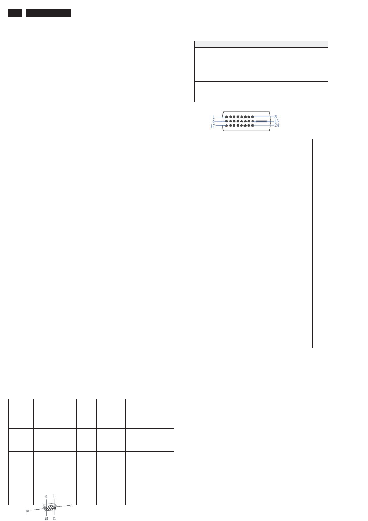
PIN No. SIGNAL PIN No. SIGNAL
1 Red 9 DDC +3.3V or +5V
2 Green/ SOG 10 Logic GND
3 Blue 11 Sense (GND)
4 Sense (GND) 12 Bi-directional data
5 Cable Detect (GND) 13 H/H+V sync
6 Red GND 14 V-sync
7 Green GND 15 Data clock
8 Blue GND
Pin No. Description
1 T.M.D.S. data2-
2 T.M.D.S. data2+
3 T.M.D.S. data2 shield
4 No Connect
5 No Connect
6 DDC clock
7 DDC data
8 No Connect
9 T.M.D.S. data1-
10 T.M.D.S. data1+
11 T.M.D.S. data1 shield
12 No Connect
13 No Connect
14 +5V Power
15 Ground (for +5V)
16 Hot plug detect
17 T.M.D.S. data0-
18 T.M.D.S. data0+
19 T.M.D.S. data0 shield
20 No Connect
21 No Connect
22 T.M.D.S clock shield
23 T.M.D.S. clock+
24 T.M.D.S. clock-
ʳʳ
Susceptibility of display to external environment
Operating
- Temperature : 0 to 35 degree C
- Humidity : 80% max
- Altitude : 0-3658m
- Air pressure : 600-1100 mBAR
Storage
- Temperature : -20 to 60 degree C
- Humidity : 95% max
- Altitude : 0-12192m
- Air pressure : 300-1100 mBAR
Power
Saving
DC
Power
Off
Off Off blanked< 0.5W
ʳʳ N/A < 0.5 W LED Off ʳ
Blinking
White LED
Period: 3sec
On, 3sec Off
<3s
Note: recommend at 5 to 35qC, Humidity less than 60 %
Page 4
4 222EL2 LCD
q
Technical Data
CMO
Type NR. : CMO M215H3-LA1
Resolution : 1920x1080 (Full HD)
Outside dimensions : 495.6(H) x 292.2(V) x 11.5(D) Typ
Pitch (mm) : 0.248mm x 0.248mm
Color pixel
arrangement
Display surface
Color depth : 16.7M (8 bit with A-FRC)
Backlight : LED Blacklight
Active area (W x H) : 476.64(H) × 268.11(V) mm
View angle (CR=10) : >=160 for Right/Left (Typ)
: >=160 for Up/Down (Typ)
Contrast ratio : >=1000:1 (Typ)
White luminance : 250 (center,Typ)
Color gamut : >=72%
Gate IC : Raydium / Novatek
Source IC : Raydium / Novatek
Response time : 5 ms (Typ)
Vertical frequency
range
Scanning frequencies
Hor.: 30 – 83 K Hz
Ver.: 56 - 76 Hz
Video dot rate: D-sub < 205 MHz ; DVI < 165 MH)
Power input: 90-264 V AC, 50/60 r 3 Hz
Power consumption: Normal on: < 30 W (max)
Functions:
(1) D-SUB analog R/G/B separate inputs, H/V sync
separated, Composite (H+V) TTL level, SOG sync.
(2) DVI digital Panel Link TMDS inputs.
Ambient temperature: 0
Power input connection
Power cord length : 1.8 M
Power cord type : 3 leads power cord with protective earth plug.
Power management
The monitor must comply with the Microsoft On Now
specification, and meet EPA requirements.
Mode HSYNCVSYNCVideo Pwr-cons.IndicationRec
Power-OnOn On active <30 W
Power
Saving
DC
Power
Off
Off Off blanked< 0.5W
ʳʳ N/A < 0.5 W LED Off ʳ
: 1920 horiz. By 1080 vert
: Hard coating (3H), Anti-glare
treatment
: 50~75Hz
C - 40 qC
White LED --
(max.)
Blinking
White LED
Period: 3sec
On, 3sec Off
.
tim
e
<3s
PIN No. SIGNAL PIN No. SIGNAL
1 Red 9 DDC +3.3V or +5V
2 Green/ SOG 10 Logic GND
3 Blue 11 Sense (GND)
4 Sense (GND) 12 Bi-directional data
5 Cable Detect (GND) 13 H/H+V sync
6 Red GND 14 V-sync
7 Green GND 15 Data clock
8 Blue GND
Pin No. Description
1 T.M.D.S. data2-
2 T.M.D.S. data2+
3 T.M.D.S. data2 shield
4 No Connect
5 No Connect
6 DDC clock
7 DDC data
8 No Connect
9 T.M.D.S. data1-
10 T.M.D.S. data1+
11 T.M.D.S. data1 shield
12 No Connect
13 No Connect
14 +5V Power
15 Ground (for +5V)
16 Hot plug detect
17 T.M.D.S. data0-
18 T.M.D.S. data0+
19 T.M.D.S. data0 shield
20 No Connect
21 No Connect
22 T.M.D.S clock shield
23 T.M.D.S. clock+
24 T.M.D.S. clock-
ʳʳ
Susceptibility of display to external environment
Operating
- Temperature : 0 to 35 degree C
- Humidity : 80% max
- Altitude : 0-3658m
- Air pressure : 600-1100 mBAR
Storage
- Temperature : -20 to 60 degree C
- Humidity : 95% max
- Altitude : 0-12192m
- Air pressure : 300-1100 mBAR
Note: recommend at 5 to 35qC, Humidity less than 60 %
Page 5
Technical Data
q
222EL2 LCD 5
AUO
Type NR. : AUO M215HW01 VB
Resolution : 1920x1080 (Full HD)
Outside dimensions : 495.6(H) x 292.2(V) x 9.9(D) Typ
Pitch (mm) : 0.248mm x 0.248mm
Color pixel
arrangement
Display surface
: 1920 horiz. By 1080 vert
: Hard coating (3H), Anti-glare
treatment
Color depth : 16.7M (8 bit with A-FRC)
Backlight : LED Blacklight
Active area (W x H) : 476.64(H) × 268.11(V) mm
View angle (CR=10) : >=160 for Right/Left (Typ)
: >=160 for Up/Down (Typ)
Contrast ratio : >=1000:1 (Typ)
White luminance : 250 (center,Typ)
Color gamut : >=72%
Gate IC : Raydium / Novatek
Source IC : Raydium / Novatek
Response time : 5 ms (Typ)
Vertical frequency
range
: 50~75Hz
Scanning frequencies
Hor.: 30 – 83 K Hz
Ver.: 56 - 76 Hz
Video dot rate: D-sub < 205 MHz ; DVI < 165 MH)
Power input: 90-264 V AC, 50/60 r 2 Hz
Power consumption: Normal on: < 30 W (max)
Functions:
(1) D-SUB analog R/G/B separate inputs, H/V sync
separated, Composite (H+V) TTL level, SOG sync.
(2) DVI digital Panel Link TMDS inputs.
Ambient temperature: 0
C - 40 qC
Power input connection
Power cord length : 1.8 M
Power cord type : 3 leads power cord with protective earth plug.
Power management
The monitor must comply with the Microsoft On Now
specification, and meet EPA requirements.
Mode HSYNCVSYNCVideo Pwr-cons.IndicationRec
.
tim
e
Power-OnOn On active <30 W
(max.)
White LED --
PIN No. SIGNAL PIN No. SIGNAL
1 Red 9 DDC +3.3V or +5V
2 Green/ SOG 10 Logic GND
3 Blue 11 Sense (GND)
4 Sense (GND) 12 Bi-directional data
5 Cable Detect (GND) 13 H/H+V sync
6 Red GND 14 V-sync
7 Green GND 15 Data clock
8 Blue GND
Pin No. Description
1 T.M.D.S. data22 T.M.D.S. data2+
3 T.M.D.S. data2 shield
4 No Connect
5 No Connect
6 DDC clock
7 DDC data
8 No Connect
9 T.M.D.S. data110 T.M.D.S. data1+
11 T.M.D.S. data1 shield
12 No Connect
13 No Connect
14 +5V Power
15 Ground (for +5V)
16 Hot plug detect
17 T.M.D.S. data018 T.M.D.S. data0+
19 T.M.D.S. data0 shield
20 No Connect
21 No Connect
22 T.M.D.S clock shield
23 T.M.D.S. clock+
24 T.M.D.S. clock-
ʳʳ
Susceptibility of display to external environment
Operating
- Temperature : 0 to 35 degree C
- Humidity : 80% max
- Altitude : 0-3658m
- Air pressure : 600-1100 mBAR
Storage
- Temperature : -20 to 60 degree C
- Humidity : 95% max
- Altitude : 0-12192m
- Air pressure : 300-1100 mBAR
Power
Saving
DC
Power
Off
Off Off blanked< 0.5W
ʳʳ N/A < 0.5 W LED Off ʳ
Blinking
White LED
Period: 3sec
On, 3sec Off
<3s
Note: recommend at 5 to 35qC, Humidity less than 60 %
Page 6
6 222EL2 LCD
q
Technical Data
QISDA ASSEMBLY
Type NR. : ASSY M215Q01 V0
Resolution : 1920x1080 (Full HD)
Outside dimensions : 495.6(H) x 292.2(V) x 9.9(D) Typ
Pitch (mm) : 0.248mm x 0.248mm
Color pixel
arrangement
Display surface
: 1920 horiz. By 1080 vert
: Hard coating (3H), Anti-glare
treatment
Color depth : 16.7M (8 bit with A-FRC)
Backlight : LED Blacklight
Active area (W x H) : 476.64(H) × 268.11(V) mm
View angle (CR=10) : >=160 for Right/Left (Typ)
: >=160 for Up/Down (Typ)
Contrast ratio : >=1000:1 (Typ)
White luminance : 250 (center,Typ)
Color gamut : >=72%
Gate IC : Raydium / Novatek
Source IC : Raydium / Novatek
Response time : 5 ms (Typ)
Vertical frequency
range
: 50~75Hz
Scanning frequencies
Hor.: 30 – 83 K Hz
Ver.: 56 - 76 Hz
Video dot rate: D-sub < 205 MHz ; DVI < 165 MH)
Power input: 90-264 V AC, 50/60 r 2 Hz
Power consumption: Normal on: < 30 W (max)
Functions:
(1) D-SUB analog R/G/B separate inputs, H/V sync
separated, Composite (H+V) TTL level, SOG sync.
(2) DVI digital Panel Link TMDS inputs.
Ambient temperature: 0
C - 40 qC
Power input connection
Power cord length : 1.8 M
Power cord type : 3 leads power cord with protective earth plug.
Power management
The monitor must comply with the Microsoft On Now
specification, and meet EPA requirements.
Mode HSYNCVSYNCVideo Pwr-cons.IndicationRec
.
tim
e
Power-OnOn On active <30 W
(max.)
White LED --
PIN No. SIGNAL PIN No. SIGNAL
1 Red 9 DDC +3.3V or +5V
2 Green/ SOG 10 Logic GND
3 Blue 11 Sense (GND)
4 Sense (GND) 12 Bi-directional data
5 Cable Detect (GND) 13 H/H+V sync
6 Red GND 14 V-sync
7 Green GND 15 Data clock
8 Blue GND
Pin No. Description
1 T.M.D.S. data22 T.M.D.S. data2+
3 T.M.D.S. data2 shield
4 No Connect
5 No Connect
6 DDC clock
7 DDC data
8 No Connect
9 T.M.D.S. data110 T.M.D.S. data1+
11 T.M.D.S. data1 shield
12 No Connect
13 No Connect
14 +5V Power
15 Ground (for +5V)
16 Hot plug detect
17 T.M.D.S. data018 T.M.D.S. data0+
19 T.M.D.S. data0 shield
20 No Connect
21 No Connect
22 T.M.D.S clock shield
23 T.M.D.S. clock+
24 T.M.D.S. clock-
ʳʳ
Susceptibility of display to external environment
Operating
- Temperature : 0 to 35 degree C
- Humidity : 80% max
- Altitude : 0-3658m
- Air pressure : 600-1100 mBAR
Storage
- Temperature : -20 to 60 degree C
- Humidity : 95% max
- Altitude : 0-12192m
- Air pressure : 300-1100 mBAR
Power
Saving
DC
Power
Off
Off Off blanked< 0.5W
ʳʳ N/A < 0.5 W LED Off ʳ
Blinking
White LED
Period: 3sec
On, 3sec Off
<3s
Note: recommend at 5 to 35qC, Humidity less than 60 %
Page 7
Installation
222EL2 LCD 7
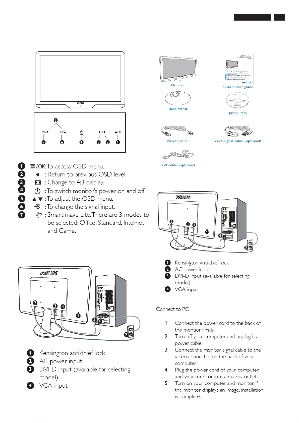
Front View Product Description
Accessory Pack
Unpack all the parts
Connecting to Your PC
1) Connect the power cord to the back of the monitor firmly.
(Philips has pre-connected VGA cable for the first installation.
Rear View
ʳ
Page 8
8 222EL2 LCD
ʳ
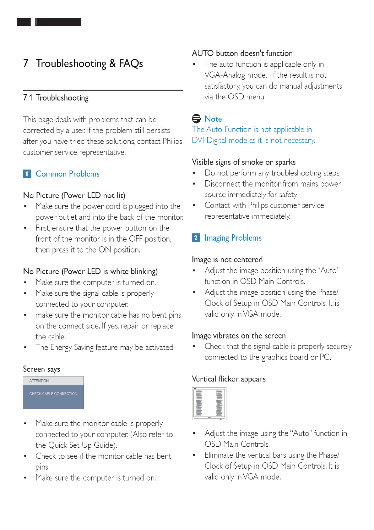
Troubleshooting
Page 9
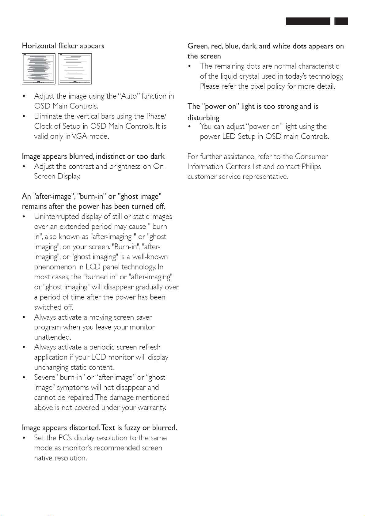
Troubleshooting
222EL2 LCD 9
Page 10
10 222EL2 LCD
ʳ
ʳ
ʳ
On-Screen Display
Description of the On Screen Display
What is the On-Screen Display?
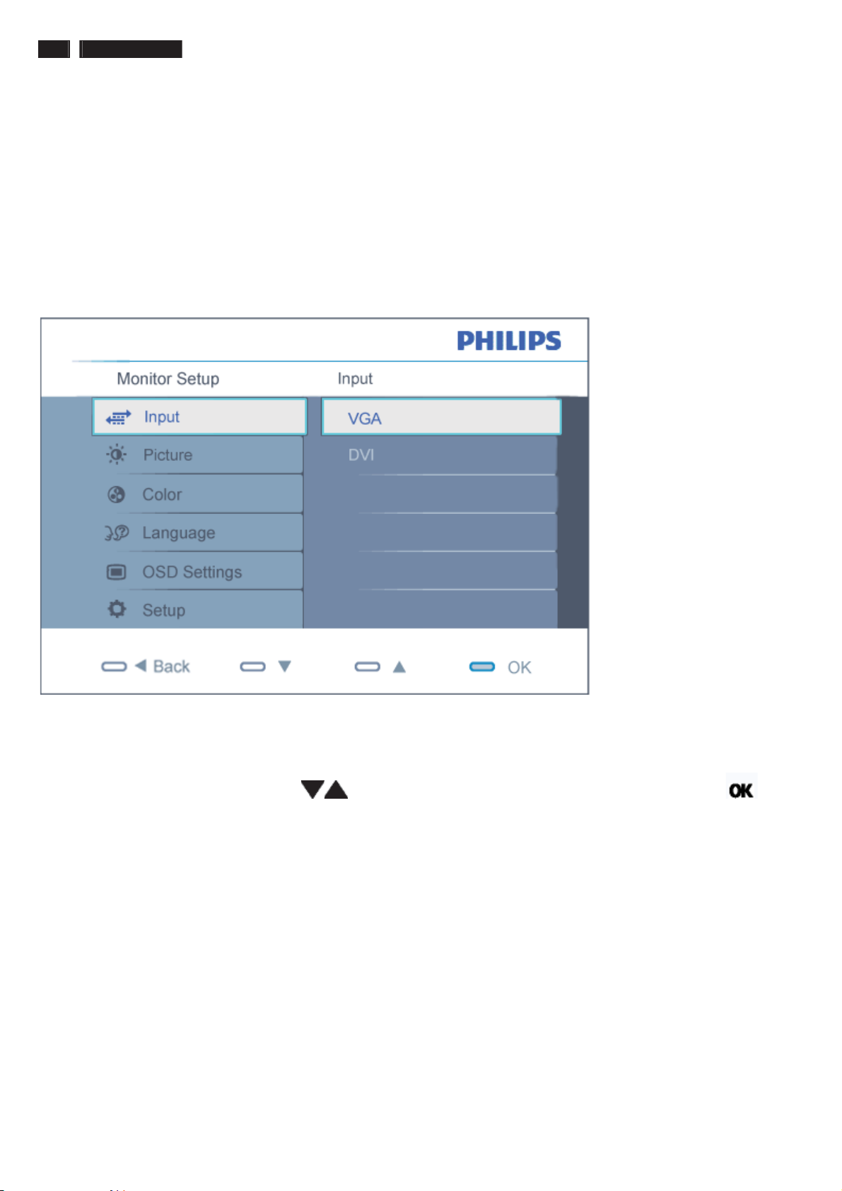
On-Screen Display (OSD) is a feature in all Philips LCD monitors. It allows an end user to adjust screen performance or
select functions of the monitors directly through an on-screen instruction window. A user friendly on screen display
interface is shown as below :
ʳ
ʳ
Basic and simple instruction on the control keys.
In the OSD shown above users can press buttons at the front bezel of the monitor to move the cursor, to
confirm the choice or change.
ʳ
ʳʳ
Page 11
On-Screen Display
ʳ
ʳ
ʳ
222EL2 LCD 11
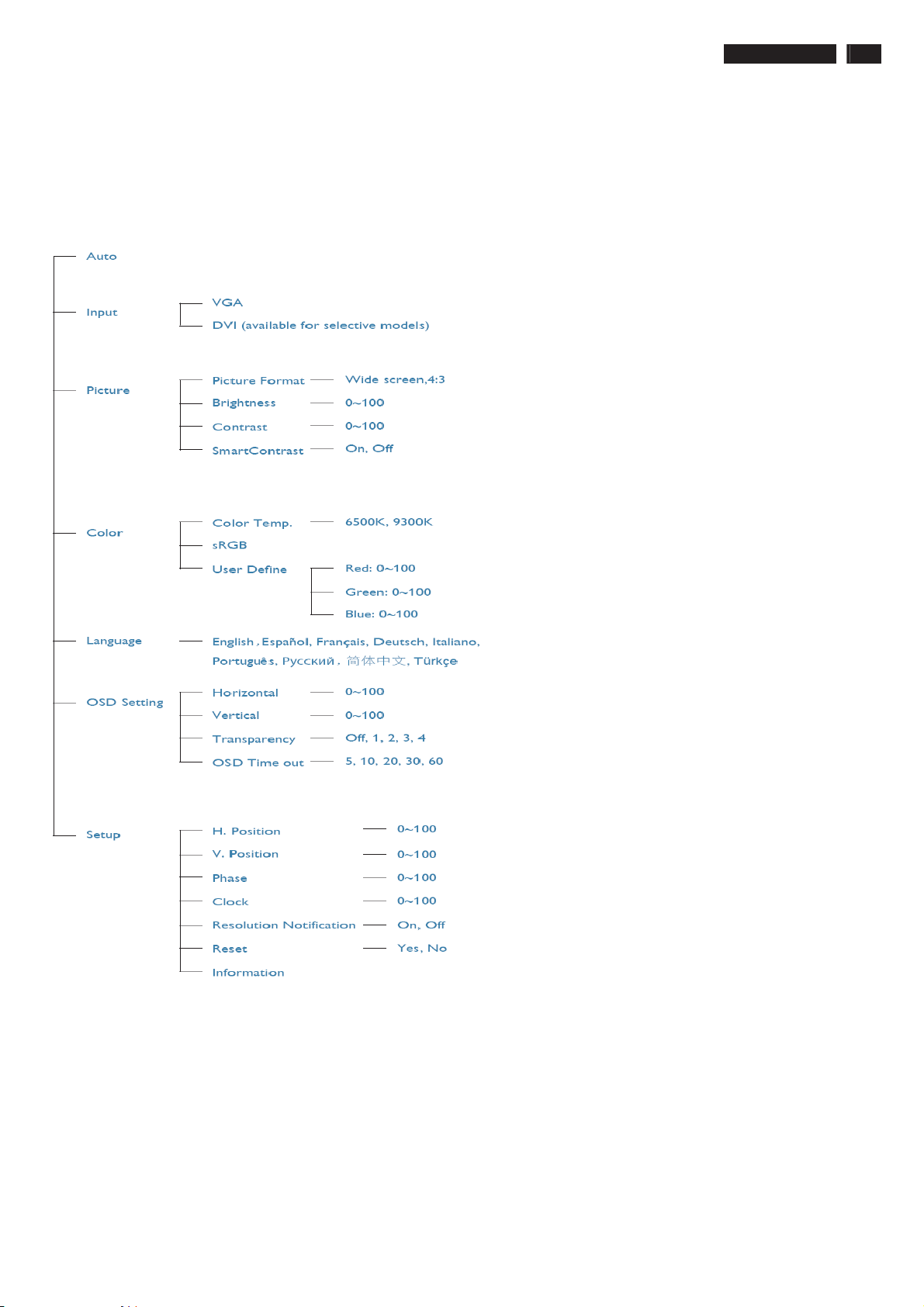
The OSD Tree
Below is an overall view of the structure of the On-Screen Display. You can use this as a reference when you want to work
your way around the different adjustments later on.
ʳ
ʳ
Resolution notification
This monitor is designed for optimal performance at its native resolution, 1920X1080@60Hz. When the monitor is powered
on at a different resolution, an alert is displayed on screen: Use 1920X1080@60Hz for best results.
Display of the native resolution alert can be switched off from Setup in the OSD (On Screen Display) menu.ʳ
ʳ
Page 12
12 222EL2 LCD
/RFN8QORFN$JLQJ)DFWRU\0RGH
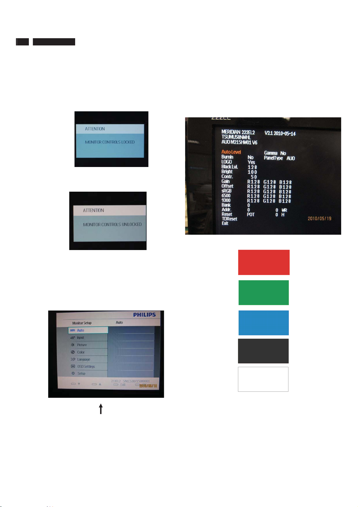
To lock/unlock OSD FUNCTION(User Mode)
The OSD function can be locked by pressing"OK"button(1) for more than 10
seconds, the screen shows following windows for 4 seconds. Every time
when you press"OK" button, this message appears on the screen
automatically .
Unlock OSD function
Unlocked OSD function can be released by pressing "OK" button for more
than 10 seconds again.
$FFHVV)DFWRU\0RGH
1). Turn off monitor.
2).[Push "EXIT" & "MENU" buttons at the same time and hold them]+[Press
"power" button until comes out "Windows screen" ]=> then release all
buttons
3).Press "MENU" button, wait until the OSD menu with Characters
"MERIDIAN 222EL2 V2.1 2010-05-14” (below OSD menu) come on the
Screen of the monitor.
value until snowy noise completely disappear .
$FFHVV$JLQJ0RGH
Step 1 : Access Factory Mode then enter Factory Menu.
Step 2 : By pressing " UP" and " DOWN " key to Burning Icon. Press
"MENU then press " UP" and "DOWN " key to turn on Aging Mode.
Step 3 : Disconnect interface cable between Monitor and PC.
After 3 seconds,
bring up:
Factory Mode indicator
Factory Menu
Cursor can move on gray color area
Hot key function: by pressing " UP " and " DOWN " key Simultaneously at
User Mode (or Factory Mode) (PS: The Of fset R G B function can be used
on reduce or eliminate snowy noise on the background when the resolution
of video signal is 1680*1050vertical 60Hz. Slightly increase or decrease the
repeatly
Connect Signal cable again=> go back to normal display
Page 13
222EL2 LCD 13
ʳ
ʳ
ʳ
ʳ
ʳ
ʳ
ʳ
Philips Pixel Defect Policy
Philips' Flat Panel Monitors Pixel Defect Policy
Philips strives to deliver the highest quality products. We use some of the
industry's most advanced manufacturing processes and practice stringent
quality control. However, pixel or sub pixel defects on the TFT LCD panels
used in flat panel monitors are sometimes unavoidable. No manufacturer
can guarantee that all panels will be free from pixel defects, but Philips
guarantees that any monitor with an unacceptable number of defects will be
repaired or replaced under warranty. This notice explains the different types
of pixel defects and defines acceptable defect levels for each type. In order
to qualify for repair or replacement under warranty, the number of pixel
defects on a TFT LCD panel must exceed these acceptable levels. For
example, no more than 0.0004% of the sub pixels on a 19" XGA monitor may
be defective. Furthermore, Philips sets even higher quality standards for
certain types or combinations of pixel defects that are more noticeable than
others. This policy is valid worldwide.
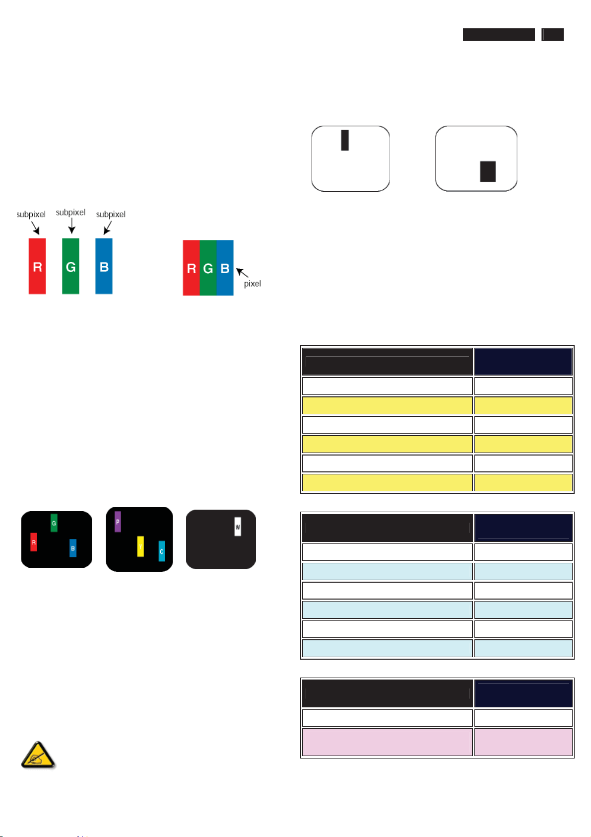
Pixels and Sub pixels
A pixel, or picture element, is composed of three sub pixels in the primary
colors of red, green and blue. Many pixels together form an image. When all
sub pixels of a pixel are lit, the three colored sub pixels together appear as a
single white pixel. When all are dark, the three colored sub pixels together
appear as a single black pixel. Other combinations of lit and dark sub pixels
appear as single pixels of other colors.
ʳTypes of Pixel Defects
Pixel and sub pixel defects appear on the screen in different ways. There are
two categories of pixel defects and several types of sub pixel defects within
each category. ʳ
Bright Dot Defects Bright dot defects appear as pixels or sub pixels that are
always lit or 'on'. That is, a bright dot is a sub-pixel that stands out on the
screen when the monitor displays a dark pattern. There are the types of
bright dot defects:ʳ
Black Dot Defects Black dot defects appear as pixels or sub pixels that are
always dark or 'off'. That is, a dark dot is a sub-pixel that stands out on the
screen when the monitor displays a light pattern. These are the types of
black dot defects:ʳ
ʳ
One dark sub pixelʳ Two or three adjacent dark sub pixelsʳ
Proximity of Pixel Defects
Because pixel and sub pixels defects of the same type that are near to one
another may be more noticeable, Philips also specifies tolerances for the
proximity of pixel defects.
Pixel Defect Tolerances
In order to qualify for repair or replacement due to pixel defects during the
warranty period, a TFT LCD panel in a Philips flat panel monitor must have
pixel or sub pixel defects exceeding the tolerances listed in the following
tables.ʳ
BRIGHT DOT DEFECTSʳ
MODELʳ
1 lit subpixelʳ 3ʳ
2 adjacent lit subpixelsʳ 1ʳ
3 adjacent lit subpixels (one white pixel)ʳ 0ʳ
Distance between two bright dot defects*ʳ >15mmʳ
Total bright dot defects of all typesʳ 3ʳ
ACCEPTABLE
LEVEL ʳ
222EL2ʳ
One lit red, green or
blue sub pixelʳ
A red or blue bright dot must be more than 50 percent brighter
than neighboring dots while a green bright dot is 30 percent
ʳ
brighter than neighboring dots.ʳ
ʳ
Two adjacent lit sub
pixels:
- Red + Blue =
Purple
- Red + Green =
Yellow
- Green + Blue =
Cyan (Light Blue)!
ʳ
Three adjacent lit sub
pixels (one white
pixel)ʳ
BLACK DOT DEFECTSʳ
MODELʳ
ACCEPTABLE
LEVEL ʳ
222EL2
1 dark subpixelʳ 5 or fewerʳ
2 adjacent dark subpixelsʳ 2 or fewerʳ
3 adjacent dark subpixelsʳ 0 ʳ
Distance between two black dot defects*ʳ >15mmʳ
Total black dot defects of all typesʳ 5 or fewerʳ
TOTAL DOT DEFECTSʳ
MODELʳ
Total bright or black dot defects of all
typesʳ
Note:
* 1 or 2 adjacent sub pixel defects = 1 dot defect
ACCEPTABLE
LEVEL ʳ
222EL2
5 or fewerʳ
Page 14
14 222EL2 LCD
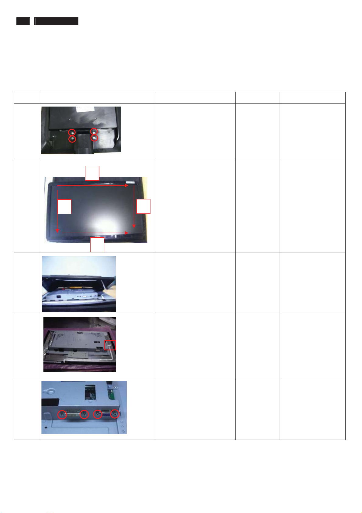
Mechanical Instruction
Preparation before disassemble
1.Clean the room for disassemble
2.Identify the area for monitor
3.Check the position that the monitors be placed and the quantity of the monitor ;prepare the area for material flow;
according to the actual condition plan the disassemble layout
4.Prepare the implement, equipments, materials as bellow:
1) Press-fixture 2)working table 3)Screw-driver 4)knife*1 5)glove 6)cleaning cloth 7)ESD protection
item picture Operation Tool Notes
1 Tear off four piece of
Mylar
Disassemble the stand
Æ 4 screws
2 disassembly the bezel from
1
the monitor, notice the
disassembly order :
1.Top (1) parts of bezel
2
4
2.Left (2) parts of bezel
3.Bottom (3) parts of bezel
4. Right (4) parts of bezel
3
Don’t draw the BZL
3 Turn over the monitor ,
Bring the Rear cover from
the monitor
Screw-driver
When disassembly
the bezel ,
notice don’t bend the
C/B .
man must wear glove
The purpose is loose
the BZL
4 Draw the control board
cable
Take the entire internal
mechanism from Bezel and
then put it on the cushion
5 Disassembled the
Main-BKT : hexagonal
screw *4
Screw-driver
Page 15
Mechanical Instruction
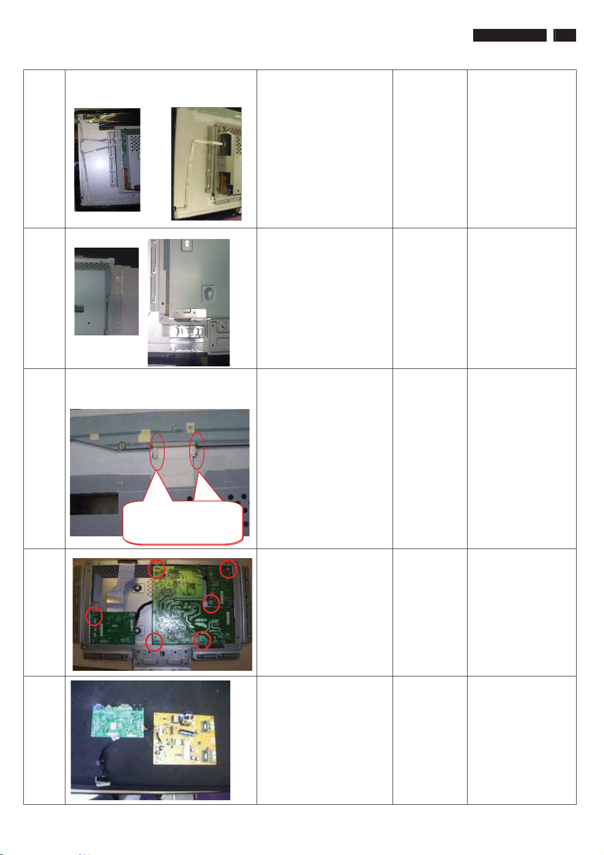
222EL2 LCD 15
6 For For
AUO panelΚ CMO panelΚ
7
For all panelΚ
For AUO panelΚ
Draw the lamp cables
Tear off the AL foils
8 Unlock the FFC by using
two hands(see note).
The locking-latch
The locking-latch
of FFC cable’s
of LVDS cable’s
9 Disassemble the Power
boardΕITF-board and LED
drive board
Æ 6 screws
Screw-driver
10
Take the PCBA from
Main-BKT and then put it
on the cushion
Page 16
16 222EL2 LCD
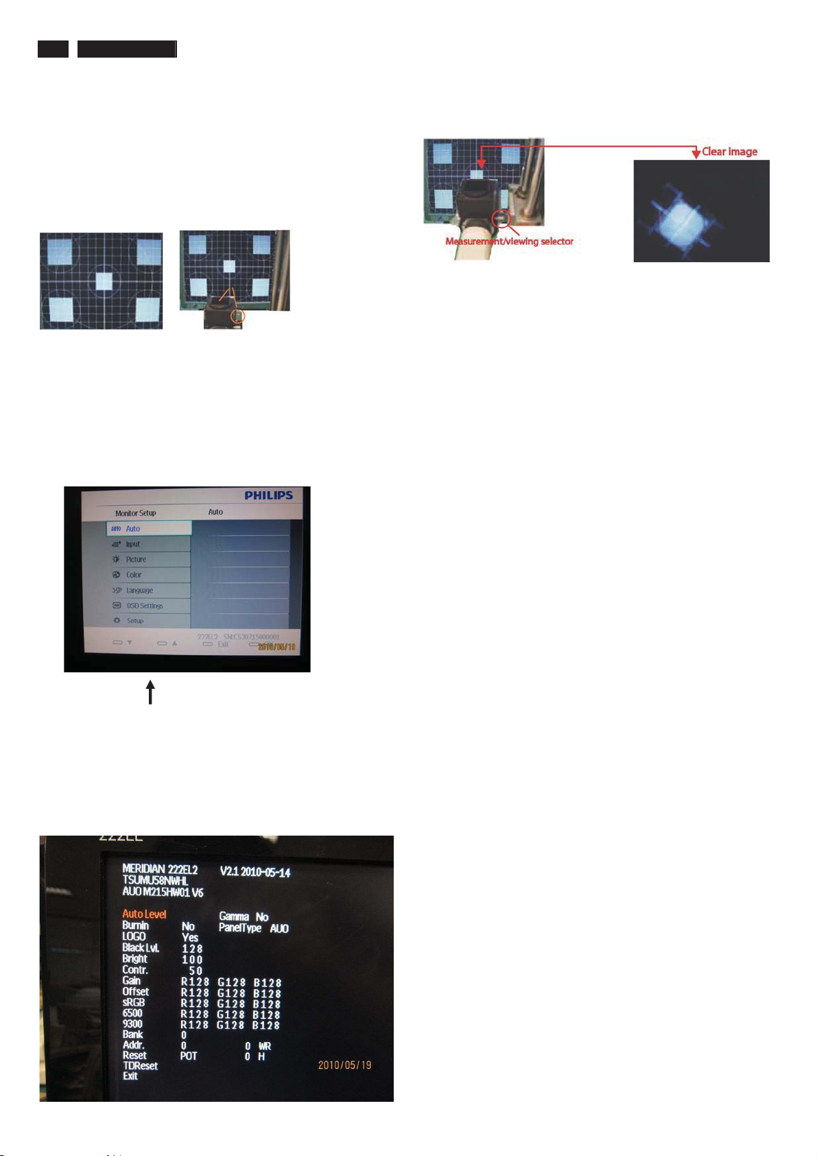
Color Adjustment
Alignment procedure
1. Turn on the LCD monitor
2. Turn on the Timing/pattern generator. See Fig.1
3. Preset LCD color Analyzer CA-1 10
-Remove the lens protective cover of probe CA-A30.
-Set measuring/viewing selector to measuring position for reset
analyzer .(zero calibration) as Fig.2
- Turn on the color analyzer (CA-1 10)
-Press 0-CAL button to starting reset analyzer .
Fig. 1 Fig.2
4. Access Factory Mode
1). Turn off monitor.
2). [Push "AUT O" & "MENU" buttons at the same time and hold them]
+[Press "power" button untill comes out "Windows screen" ]
=> then release all buttons
3).Press "MENU button, wait until the OSD menu with
Characters " MERIDIAN 222EL2 V2.1 2010-05-14” (below OSD menu)
come on the Screen of the monitor as shown in Fig3.
Factory Mode indicator
)LJ
Fig.5
5.Display
Press "UP" or "DOWN" button to select . Change the value
by "UP" or "DOWN" key until the X, Y co-ordinates as below
5.1 Color temperature adjustment
There are six factory preset white color 11500K, 9300K, 8200K, 7500K,
6500K, sRGB, 5000K
Align by Philips PerfecTune (also called FGA) function.
Apply full white pattern, with brightness in 100 % position and the contrast
control at 50 % position.
The 1931 CIE Chromaticity (color triangle) diagram (x , y) coordinate for
the screen center should be:
Product specification Production alignment spec.
9300K
6500K/sRGB
sRGB
9300K
6500K/sRGB
sRGB
x = 0.283 ± 0.02
y = 0.297 ± 0.02
x = 0.313 ± 0.02
y = 0.329 ± 0.02
x = 0.313 ± 0.02
y = 0.329 ± 0.02
x = 0.283 ± 0.02
y = 0.297 ± 0.02
x = 0.313 ± 0.02
y = 0.329 ± 0.02
x = 0.313 ± 0.02
y = 0.329 ± 0.02
9300K
6500K/sRGB
sRGB
9300K
6500K/sRGB
sRGB
x = 0.283 ± 0.006
y = 0.297 ± 0.006
x = 0.313 ± 0.006
y = 0.329 ± 0.006
x = 0.313 ± 0.006
y = 0.329 ± 0.006
x = 0.283 ± 0.006
y = 0.297 ± 0.006
x = 0.313 ± 0.006
y = 0.329 ± 0.006
x = 0.313 ± 0.006
y = 0.329 ± 0.006
)LJ
4). Press button, then select factory mode indicator by "MENU" "LEFT"
or "RIGHT" button .Press"MENU" button to bring up submenu
windows as below:
Quality Inspection specification:
9300K
6500K/sRGB
x = 0.283 ± 0.015
y = 0.297 ± 0.015
x = 0.313 ± 0.015
y = 0.329 ± 0.015
sRGB
9300K
x = 0.313 ± 0.015
y = 0.329 ± 0.015
x = 0.283 ± 0.015
y = 0.297 ± 0.015
6500K/sRGB
sRGB
x = 0.313 ± 0.015
y = 0.329 ± 0.015
x = 0.313 ± 0.015
y = 0.329 ± 0.015
Page 17
FAQs (Frequently Asked Questions)
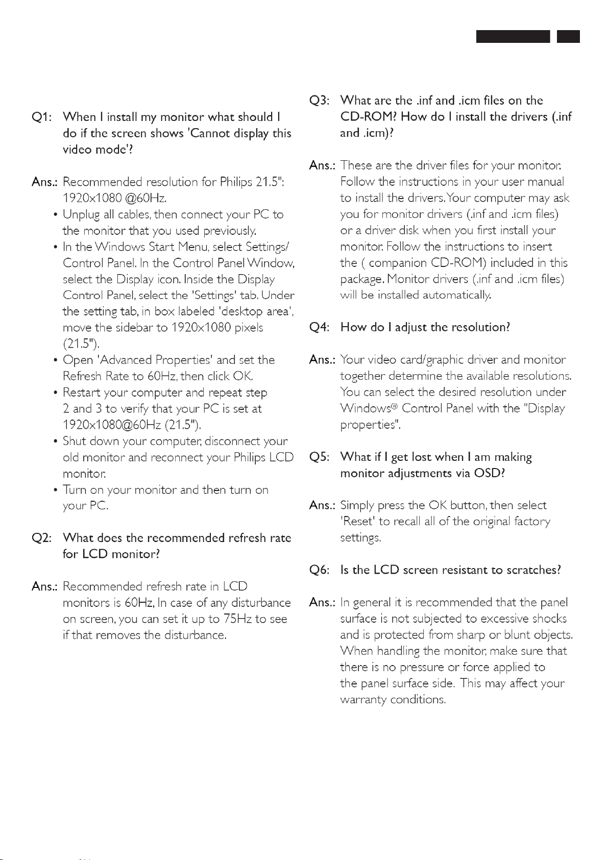
222EL2 LCD 17
Page 18
18 222EL2 LCD
FAQs (Frequently Asked Questions)
Page 19
Electrical Instructions
Electrical characteristics
1. Interface signals
1.1 D-Sub Analog
Input signal: Video, Hsync., Vsync
Video: 0.7 Vp-p, input impedance, 75 ohm @DC
Sync.: Separate sync TTL level , input impedance 2.2k ohm terminate
Hsync Positive/Negative
Vsync Positive/Negative
Composite sync TTL level, input impedance 2.2k ohm terminate
Sync on green video 0.3 Vp-p Negative (Video 0.7 Vp-p Positive)
1.2 DVI-D Digital
Input signal: Single TMDS link (Three channels: RX0-/+, RX1-/+, RX2-/+)
2. Interface
2.1 D-Sub Cable
Length : 1.8 M +/- 50 mm
Fix with monitor when packing, with transplant pin protective cover.
Connector type : D-Sub male with DDC2B pin assignments.
Blue connector thumb-operated jack screws
2.2 DVI Cable
The input signals are applied to the display through DVI-D cable.
Length : 1.8 M +/- 50 mm
Connector type : DVI-D male with DDC-2B pin assignme nts
White connector thumb-operated jackscrews
With transplant pin protective cover.
3. Timing requirement
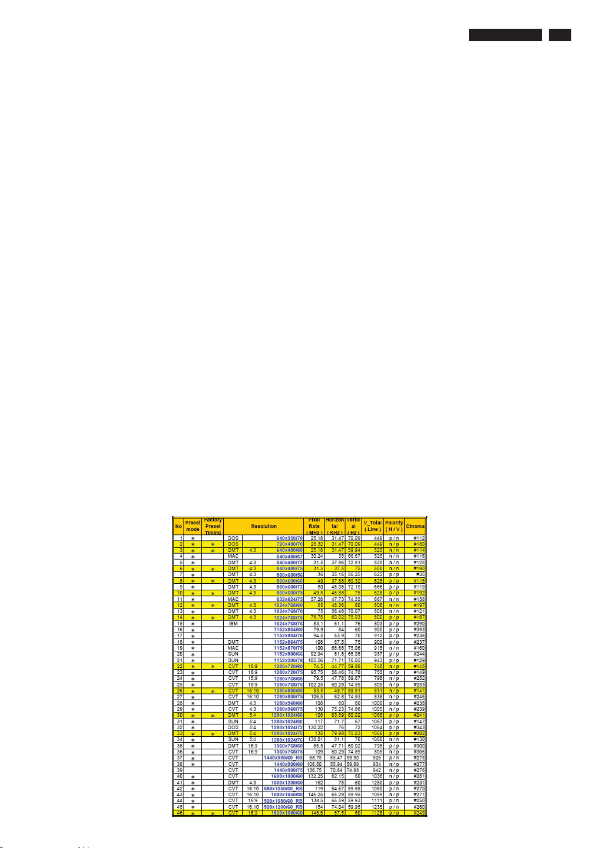
3.1 Factory Preset mode definition:
3.1.1 Perfect FOS while presenting those timings.
3.1.2 Will specify those timing in User's Manual
3.2 Preset mode definition:
3.2.1 Need to support those timings.
3.2.2 Perfect FOS after auto adjustment.
3.3 User mode
3.3.1 Can save those timing that not in Preset mode and can be showed
(not over scalar or Panel spec.)
3.3.2 It needs to reserve the 10 timings space in memory size.
3.3.3 Factory modes and preset modes are defined in the enclosed timing table file
222EL2 LCD 19
Page 20
20 222EL2 LCD
Electrical Instructions
White color adjustment
There are three factory preset white color 9300K, 6500K, sRGB.
Apply full gray64 pattern, with brightness in 100 % position and the contrast control at 50 % position.The 1931 CIE
Chromaticity (color triangle) diagram (x ,y) coordinate for the screencenter should be:
Product specification
CIE coordinates (x,y)
9300K
6500K/sRGB
sRGB
Production alignment spec.
CIE coordinates (x,y)
9300K x = 0.283 ± 0.006
6500K/sRGB x = 0.313 ± 0.006
sRGB x = 0.313 ± 0.006
x = 0.283 ± 0.02
y = 0.297 ± 0.02
x = 0.313 ± 0.02
y = 0.329 ± 0.02
x = 0.313 ± 0.02
y = 0.329 ± 0.02
y = 0.297 ± 0.006
y = 0.329 ± 0.006
y = 0.329 ± 0.006
PerfectuneII
PerfectuneII
PerfectuneII
PerfectuneII
PerfectuneII
PerfectuneII
Quality Inspection specification:
CIE coordinates (x,y)
9300K x = 0.283 ± 0.015
y = 0.297 ± 0.015
6500K/sRGB x = 0.313 ± 0.015
y = 0.329 ± 0.015
sRGB x = 0.313 ± 0.015
y = 0.329 ± 0.015
Page 21
Service tool-Hardware
PCM code 12NC
5E.L8215.001 996510019769
222EL2 LCD 21
Page 22
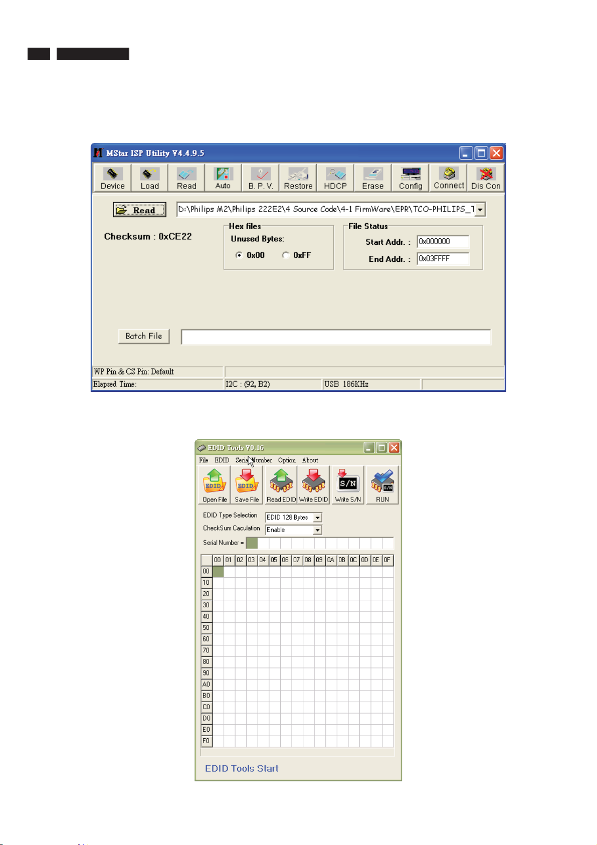
22 222EL2 LCD
Service tool-Software
Firmware writing tool : MStar ISP Utility V4.4.9.5
DDC writing tool: Q-EDID-V16
Page 23
222EL2 LCD 23
DDC Instructions
DDC Data Re-programming
In case the DDC data memory IC or main EEPROM which storage all factory settings were
replaced due to a defect, the serial numbers have to be re-programmed "Analog
DDC IC, Digital DDC IC & EEPROM".
It is advised to re-soldered DDC IC and main EEPROM from the old board onto the new
board if circuit board have been replaced, in this case the DDC data does not need to be
re-programmed.
Additional information
Additional information about DDC (Display Data Channel) may be obtained from Video
Electronics Standards Association (VESA).
Extended Display Identification Data(EDID) information may be also obtained from
VESA.
Configuration and procedure
"PI-EDID" The software is provided by IMS to upgrade the firmware of CPU.
PI-EDID Tools is for the interface between "Parallel Port of PC" and "15 pin-D-SUB
connector of Monitor".
It is a windows-based program, which cannot be run in MS-DOS.
System and equipment requirements
1. An Pentium (or above) personal computer or compatible.
2. Microsoft operation system Windows 95/98/2000/XP and Port95NT.exe.
3. EDID Software "PI-EDID.exe"
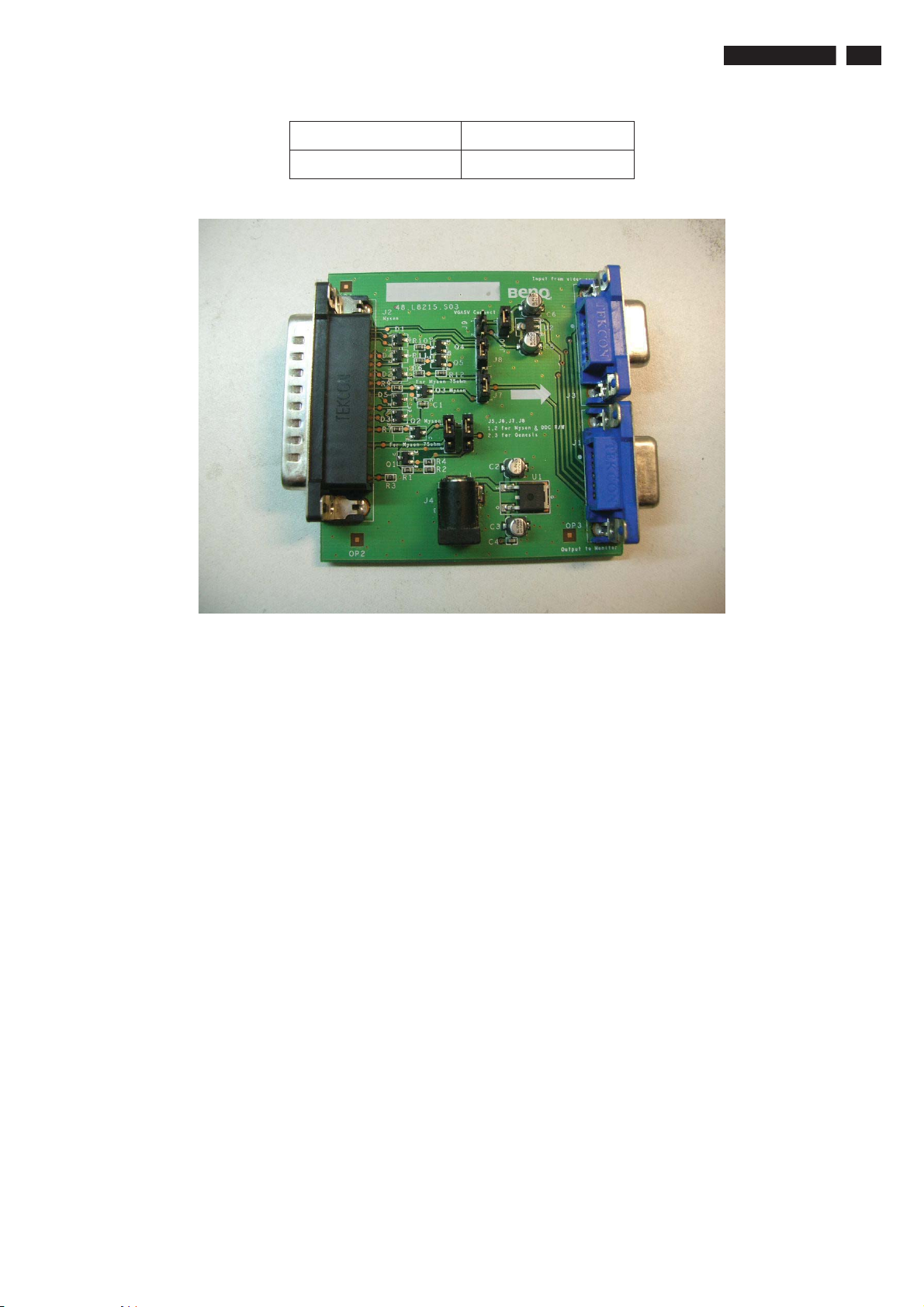
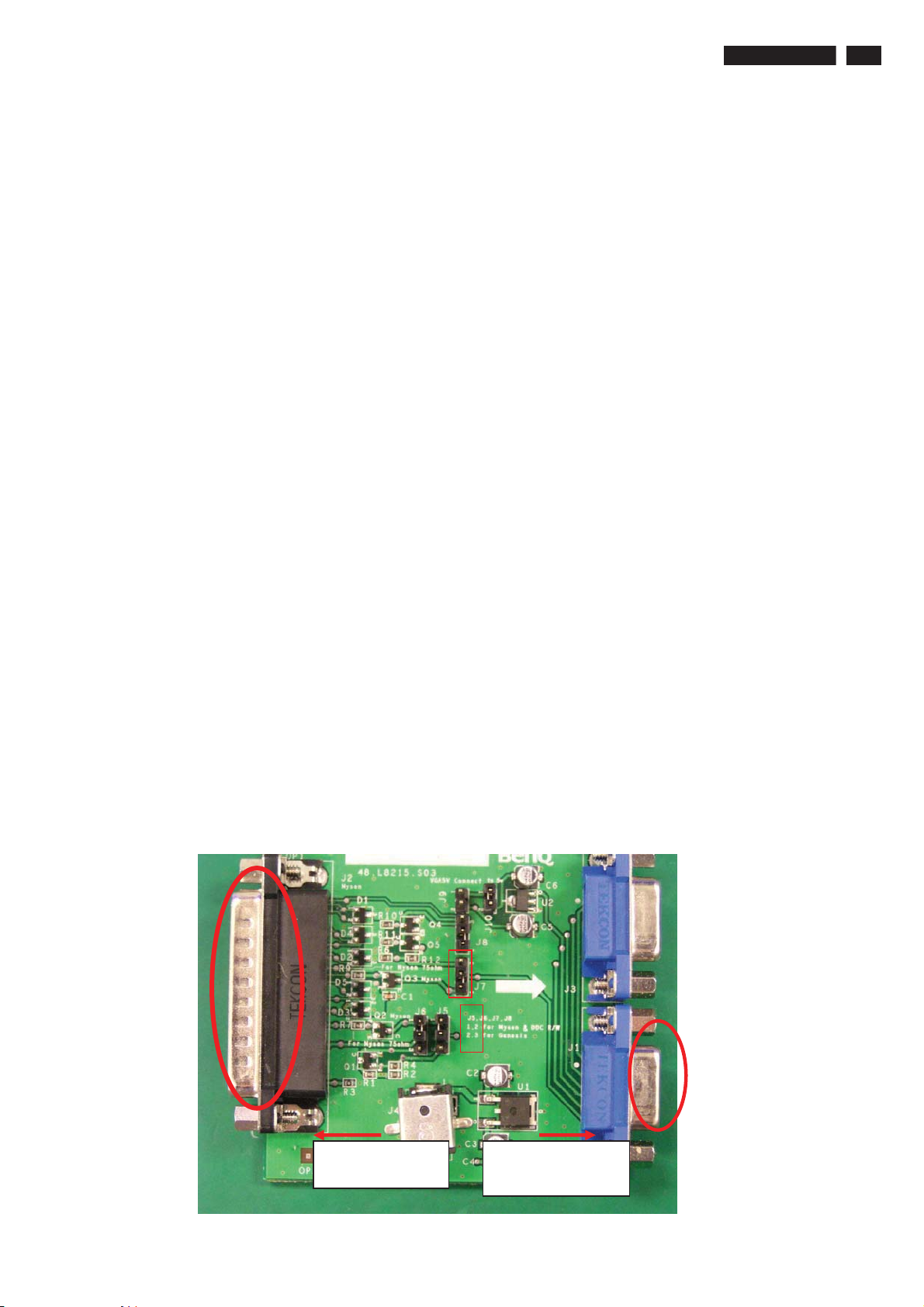
4. ISP boardas shown in Fig. 1
And I2C Board Jump wire should follow J10 (short), J9 (open), J5/J6/ (1and 2 pin short)
J7/J8 (1 and 2 pin short)
3
2
Connected to print
cord and PC
Fig.1
1
2
Connected to Display
Signal Cable
Page 24
24 222EL2 LCD
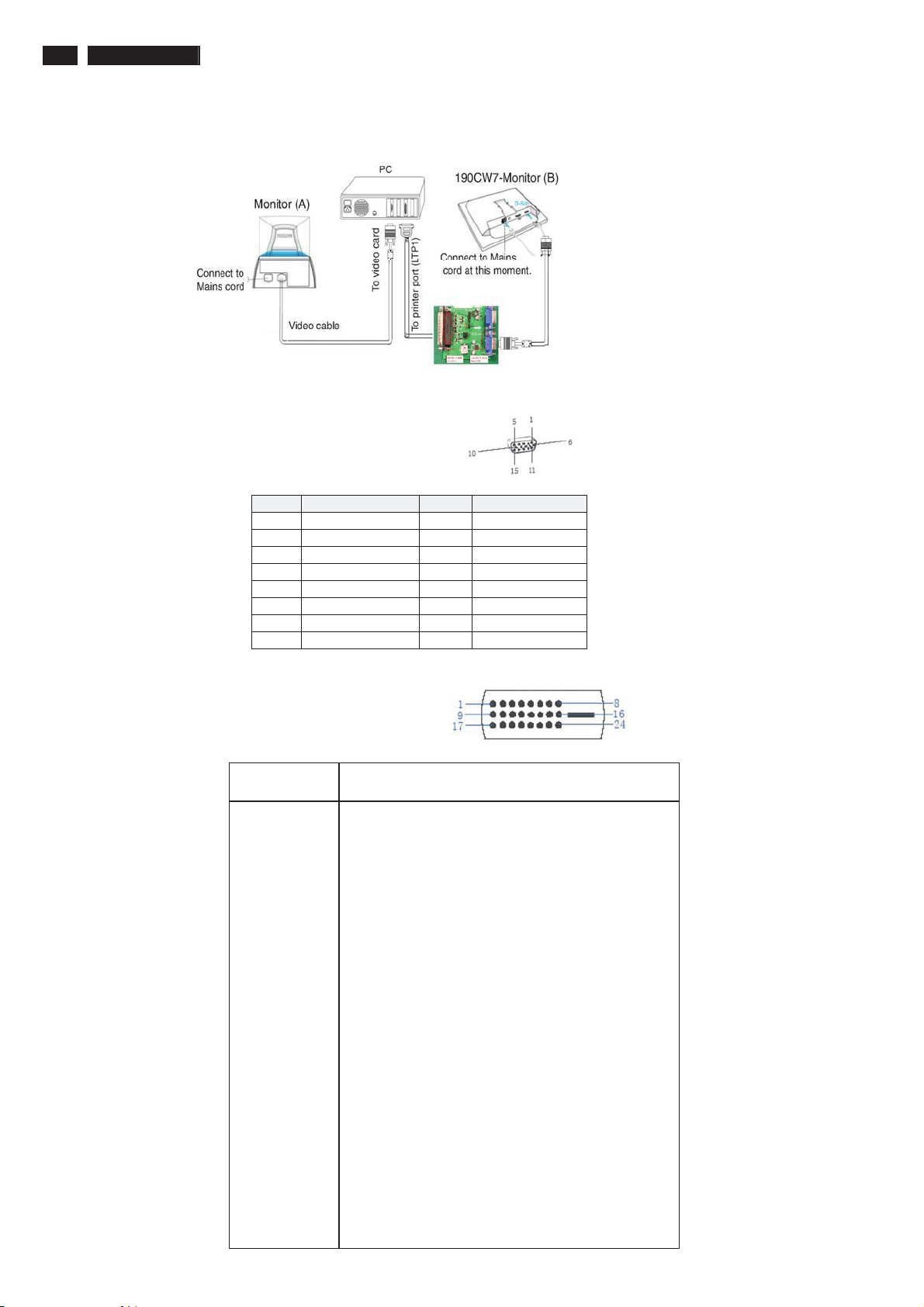
5. Connect and Mains cord to Monitor as shown in Fig.2.
Pin assignments :
A. 15-pin D-Sub Connector
DDC Instructions
Fig.2
PIN No. SIGNAL PIN No. SIGNAL
1 Red 9 DDC +3.3V or +5V
2 Green/ SOG 10 Logic GND
3 Blue 11 Sense (GND)
4 Sense (GND) 12 Bi-directional data
5 Cable Detect (GND) 13 H/H+V sync
6 Red GND 14 V-sync
7 Green GND 15 Data clock
8 Blue GND
ʳʳ
B. Input DVI-D Connector pin
Description
Pin No.
1 T.M.D.S. data2-
2 T.M.D.S. data2+
3 T.M.D.S. data2 shield
4 No Connect
5 No Connect
6 DDC clock
7 DDC data
8 No Connect
9 T.M.D.S. data1-
10 T.M.D.S. data1+
11 T.M.D.S. data1 shield
12 No Connect
13 No Connect
14 +5V Power
15 Ground (for +5V)
16 Hot plug detect
17 T.M.D.S. data0-
18 T.M.D.S. data0+
19 T.M.D.S. data0 shield
20 No Connect
21 No Connect
22 T.M.D.S clock shield
23 T.M.D.S. clock+
24 T.M.D.S. clock-
Page 25
222EL2 LCD 25
DDC Instructions
6. Setup the Philips-IMS EDID Tools program
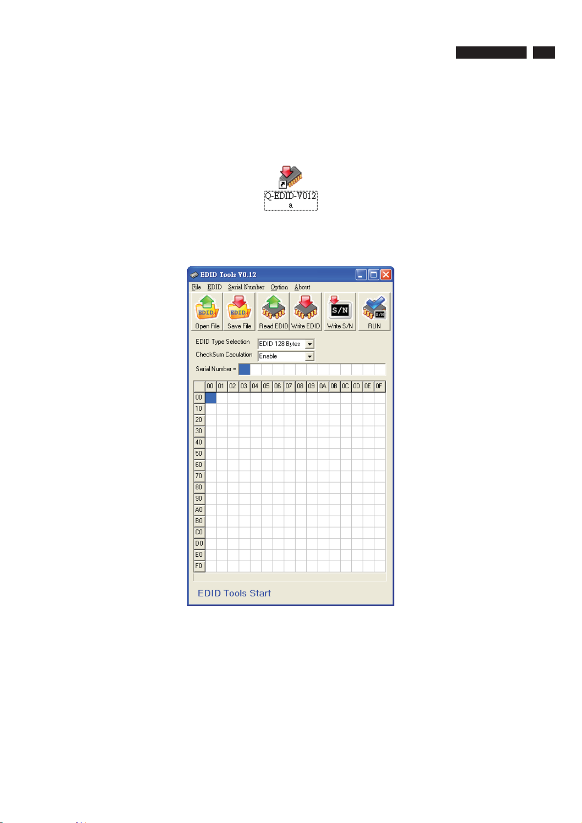
Step 1: Open Q-EDID Software into your folder as shown in Fig.3. and Fig.4.
Fig.3
Fig.4
Page 26
26 222EL2 LCD
DDC Instructions
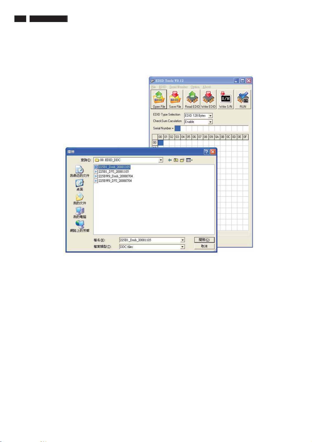
Step 2: Press “Open File” then choose
LCD_Analog.ddc or LCD_DVI.ddc as shown in Fig. 5 .
Fig.5
Page 27
DDC Instructions
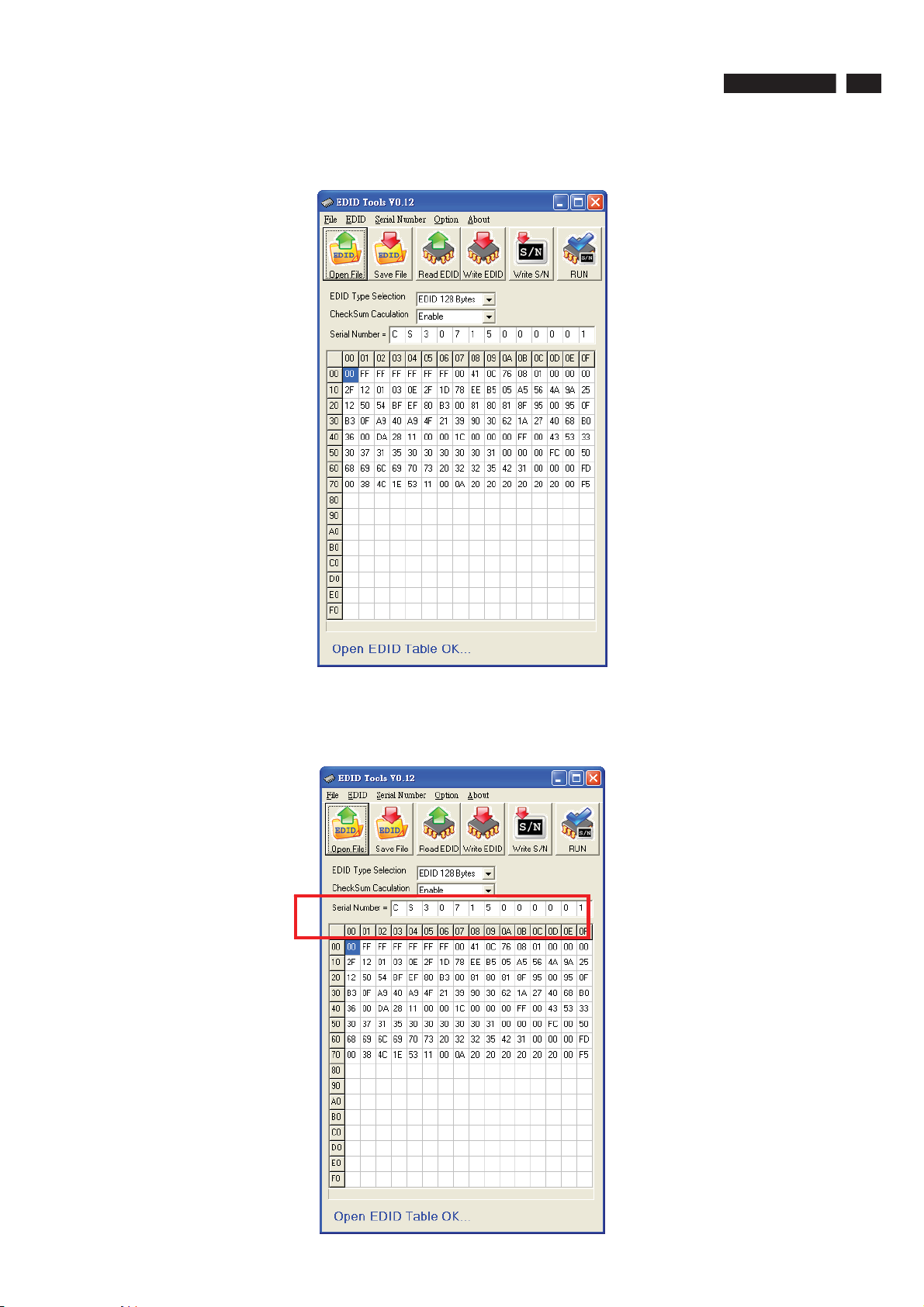
Step 3 : Load DDC file success as shown in Fig. 6 .
222EL2 LCD 27
Fig.6
Step 4 : update Serial number and press enter to correct S/N number
shown as Fig.7 .
Fig.7
Page 28
28 222EL2 LCD
DDC Instructions
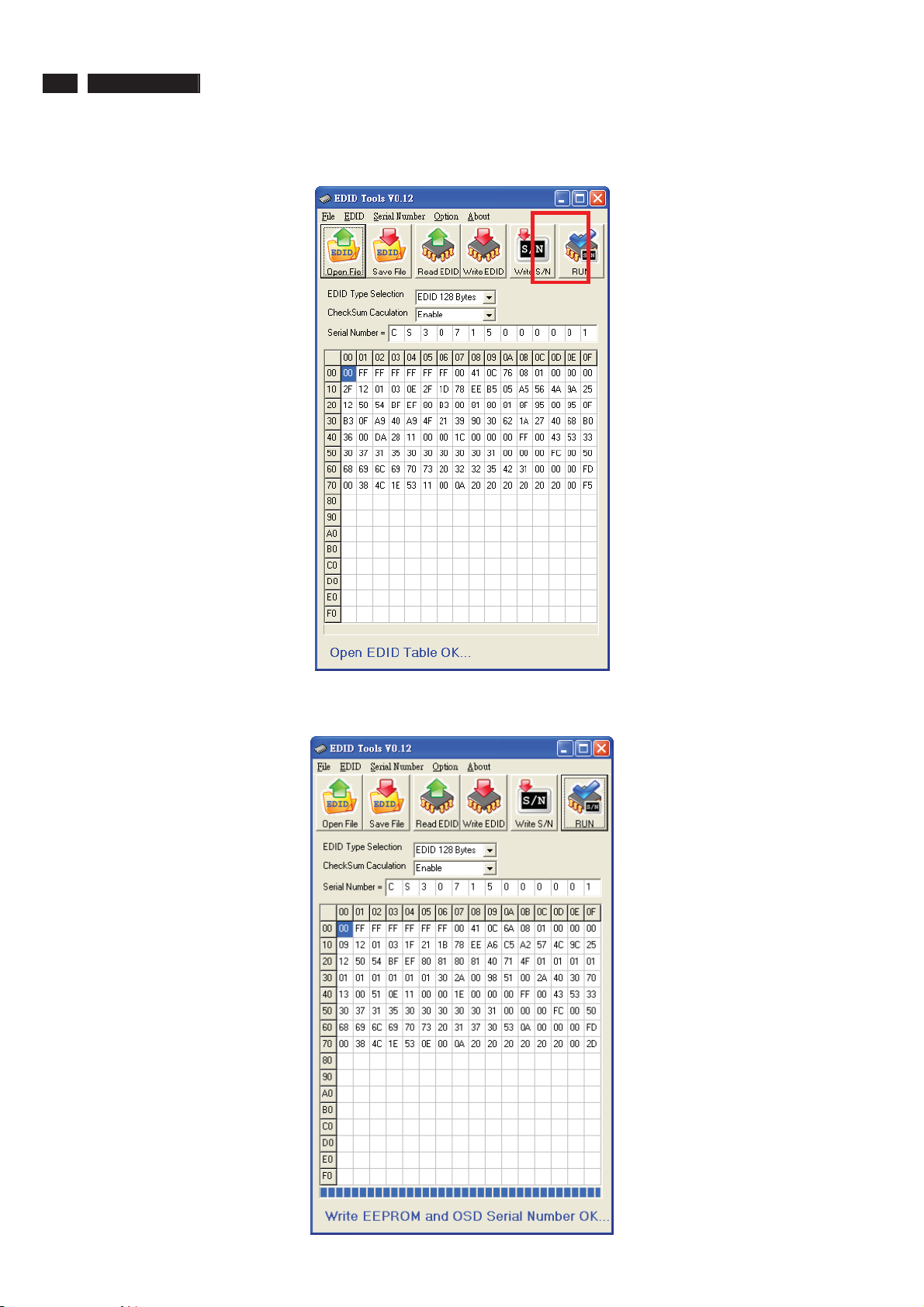
Step 5 : Press “RUN” to write EDID and serial number shown as Fig.8 .
Fig.8
Step 6 : EDID and serial number update success shown as Fig.9
Fig.9
Page 29
DDC Instructions
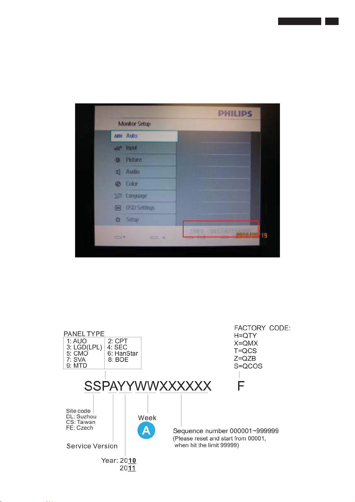
8. Press Monitor Menu Key to check OSD Serial number is the same as PI-EDID
write data as shown in Fig.10
Note: If not the same, please rewrite EDID S/N again.
222EL2 LCD 29
Fig.14
9 Turn off the monitor, exit the factory mode.
Serial Number Definition
Page 30

30 222EL2 LCD
Analog DDC
DDC DATA
//////////Displaying Monitor EDID//////////
128 bytes EDID Data (Hex):
0 1 2 3 4 5 6 7 8 9
0: 00 FF FF FF FF FF FF 00 41 0C
10: 52 C0 F1 42 0B 00 12 14 01 03
20: 6E 30 1B 78 EE EE 95 A3 54 4C
30: 99 26 0F 50 54 BF EF 80 D1 C0
40: 81 C0 81 00 81 80 01 01 01 01
50: 01 01 01 01 02 3A 80 18 71 38
60: 2D 40 58 2C 45 00 DC 0C 11 00
70: 00 1E 00 00 00 FF 00 44 4C 31
80: 31 30 31 38 37 33 38 30 33 33
90: 00 00 00 FC 00 50 68 69 6C 69
100: 70 73 20 32 32 32 45 4C 00 00
110: 00 FD 00 38 4C 1E 53 15 00 0A
120: 20 20 20 20 20 20 00 E5
Decoded EDID data
<---Header--->
Header: 00 FF FF FF FF FF FF 00
<-x-Header-x->
<---Vendor/Product Identification--->
ID Manufacturer Name: PHL
ID Product Code: 49234
ID Serial Number: 000B42F1
Week of Manufacture: 18
Year of Manufacture: 2010
<-x-Vendor/Product Identification-x->
<---EDID Structure Version/Revision--->
EDID Version#: 1
EDID Revision#: 3
<-x-EDID Structure Version/Revision-x->
<---Basic Display Parameters/Features--->
Video i/p definition: VGA
Setup: Blank-to-Black not expected
Seperate Syncs. support: Yes
Composite Sync. support: Yes
Vsync. Pulse: serration required
Max Horz Image Size: 48 cm.
Max Vert Image Size: 27 cm.
Display Gamma: 2.2
Display Type: RGB color display
Standard Default Color Space: Yes
Features, PTiming Mode: In first detailed block
Features, GTF support: No
DPMS Features, Stand-by: Yes
DPMS Features, Suspend: Yes
DPMS Features, Active Off: Yes
<-x-Basic Display Parameters/Features-x->
<---Color Characteristics--->
Red x: 0.639648
Red y: 0.330078
Green x: 0.299805
Green y: 0.599609
Blue x: 0.150391
Blue y: 5.95703e-002
White x: 0.313477
White y: 0.329102
<-x-Color Characteristics-x->
<---Established Timings--->
Established Timimgs 1: BF
- 720x400 @70Hz
- 640x480 @60Hz
- 640x480 @67Hz
- 640x480 @72Hz
- 640x480 @75Hz
- 800x600 @56Hz
- 800x600 @60Hz
Established Timimgs 2: EF
- 800x600 @72Hz
- 800x600 @75Hz
- 832x624 @75Hz
- 1024x768 @60Hz
- 1024x768 @70Hz
- 1024x768 @75Hz
- 1280x1024 @75Hz
- 1152x870x75Hz
Established Timings 3: 80
<-x-Established Timings-x->
<---Standard Timing Identification--->
Standard Timing: 1920x1080 @60Hz
Standard Timing: 1280x720 @60Hz
Standard Timing: 1280x1280 @60Hz
Standard Timing: 1280x1024 @60Hz
<-x-Standard Timing Identification-x->
<---Detailed Timing Descriptions--->
Detailed Timing: 1920x1080 @60Hz
Detailed Timing: FF (Monitor SN) 'DL11018738033'
Detailed Timing: FC (Monitor name) 'Philips 222EL'
Detailed Timing: FD (Monitor limits)
Vert: 56 - 76 Hz
Horz: 30 - 83 KHz
Clk: 210 MHz
<-x-Detailed Timing Descriptions-x->
Extension Flag: 00
Checksum: E5
Page 31

DVI DDC
222EL2 LCD 31
DDC DATA
//////////Displaying Monitor EDID//////////
128 bytes EDID Data (Hex):
0 1 2 3 4 5 6 7 8 9
0: 00 FF FF FF FF FF FF 00 41 0C
10: 51 C0 D2 04 00 00 0A 14 01 03
20: 80 30 1B 78 EE EE 95 A3 54 4C
30: 99 26 0F 50 54 BF EF 80 D1 C0
40: 81 C0 81 00 81 80 8B C0 95 00
50: B3 00 01 01 02 3A 80 18 71 38
60: 2D 40 58 2C 45 00 DC 0C 11 00
70: 00 1E 00 00 00 FF 00 43 53 33
80: 30 37 31 35 30 30 30 30 30 31
90: 00 00 00 FC 00 50 68 69 6C 69
100: 70 73 20 32 32 32 45 0A 00 00
110: 00 FD 00 38 4C 1E 53 11 00 0A
120: 20 20 20 20 20 20 00 09
<---Header--->
Decoded EDID data
<---Header--->
Header: 00 FF FF FF FF FF FF 00
<-x-Header-x->
<---Vendor/Product Identification--->
ID Manufacturer Name: PHL
ID Product Code: 49233
ID Serial Number: 000004D2
Week of Manufacture: 10
Year of Manufacture: 2010
<-x-Vendor/Product Identification-x->
<---EDID Structure Version/Revision--->
EDID Version#: 1
EDID Revision#: 3
<-x-EDID Structure Version/Revision-x->
<---Basic Display Parameters/Features--->
Video i/p definition: Digital
Setup: Blank-to-Black not expected
Seperate Syncs. support: No
Composite Sync. support: No
Vsync. Pulse: serration not required
Max Horz Image Size: 48 cm.
Max Vert Image Size: 27 cm.
Display Gamma: 2.2
Display Type: RGB color display
Standard Default Color Space: Yes
Features, Timing Mode In first detailed block
Features, GTF support: No
DPMS Features, Stand-by: Yes
DPMS Features, Suspend: Yes
DPMS Features, Active Off: Yes
<-x-Basic Display Parameters/Features-x->
<---Color Characteristics--->
Red x: 0.639648
Red y: 0.330078
Green x: 0.299805
Green y: 0.599609
Blue x: 0.150391
Blue y: 5.95703e-002
White x: 0.313477
White y: 0.329102
<-x-Color Characteristics-x->
<---Established Timings--->
Established Timimgs 1: BF
- 720x400 @70Hz
- 640x480 @60Hz
- 640x480 @67Hz
- 640x480 @72Hz
- 640x480 @75Hz
- 800x600 @56Hz
- 800x600 @60Hz
Established Timimgs 2: EF
- 800x600 @72Hz
- 800x600 @75Hz
- 832x624 @75Hz
- 1024x768 @60Hz
- 1024x768 @70Hz
- 1024x768 @75Hz
- 1280x1024 @75Hz
- 1152x870x75Hz
Established Timings 3: 80
<-x-Established Timings-x->
<---Standard Timing Identification--->
Standard Timing: 1920x1080 @60Hz
Standard Timing: 1280x720 @60Hz
Standard Timing: 1280x1280 @60Hz
Standard Timing: 1280x1024 @60Hz
Standard Timing: 1360x765 @60Hz
Standard Timing: 1440x900 @60Hz
Standard Timing: 1680x1680 @60Hz
<-x-Standard Timing Identification-x->
<---Detailed Timing Descriptions--->
Detailed Timing: 1920x1080 @60Hz
Detailed Timing: FF (Monitor SN) 'CS30715000001'
Detailed Timing: FC (Monitor name) 'Philips 222E'
Detailed Timing: FD (Monitor limits)
Vert: 56 - 76 Hz
Horz: 30 - 83 KHz
Clk: 170 MHz
<-x-Detailed Timing Descriptions-x->
Extension Flag: 00
Checksum: 09
Page 32
32 222EL2 LCD
Firmware Upgrade for CPU
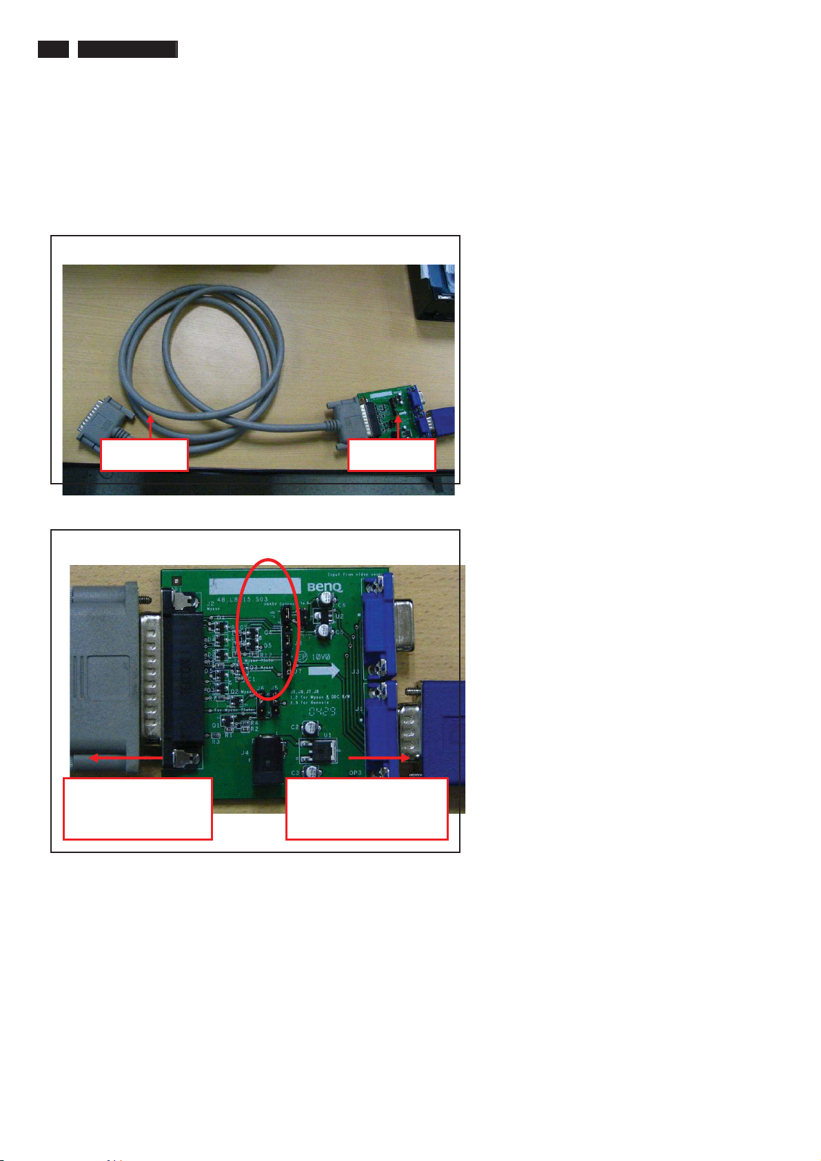
1. Hardware Requirement:
1.1. I2C board x 1 (a.Print Board b. I2C Board)
1.2. DSUB VGA cables x 2
1.3. Printer cable (with one male connector and another female connector) x 1.
1.4. PC or Notebook with parallel (printer) port x1.
Print I2C
1.5 Check the Jumpers on the I2C circuit board (make sure J5/J6/J7/J8 are set at Pin 1 & Pin 2 short)
Connected to print
cord and PC
Connected to Display
Signal Cable
Page 33
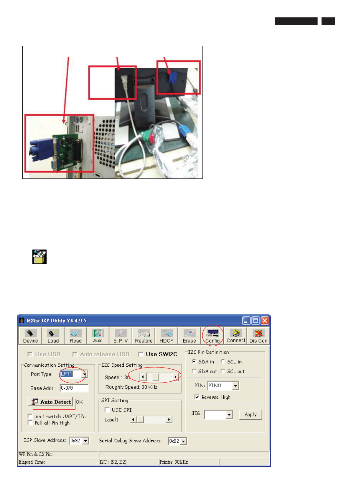
Firmware Upgrade for CPU
Link “I2C BD, Power cable and Signal cable
222EL2 LCD 33
2. Software prepare
MStar ISP Utility V4.4.9.5
MSTAR
ISP Tool 4.4.9.5
DebugTool_V6.7_200
˗ˍ˯˧˿˯ˠ˦˧˔˥˯
˜˦ˣ˲˧˿ʳˇˁˇˁˌˁˈˁ˴
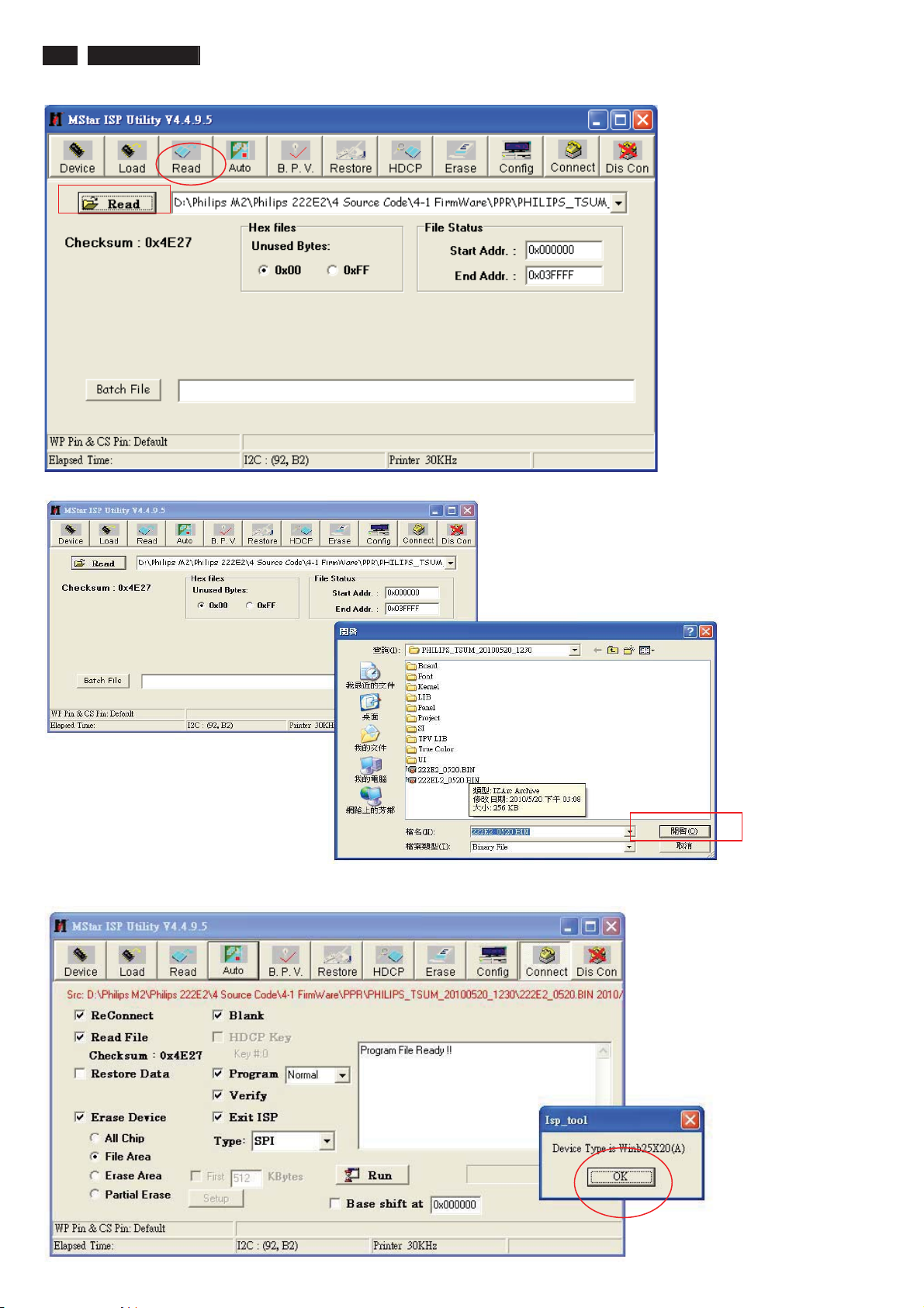
Step 1: Press MStar ISP Tool
Step 2: Choose Option “Config”, set Port type to “LPT1”; set I2C Speed Setting to 30 , Press “Auto Detect” till
the tool shows “ok”
Page 34
34 222EL2 LCD
Firmware Upgrade for CPU
Step 4: Choose Option “Connect”, the tool will show FLASH type as below, then press “OK”
Page 35
222EL2 LCD 35
Firmware Upgrade for CPU
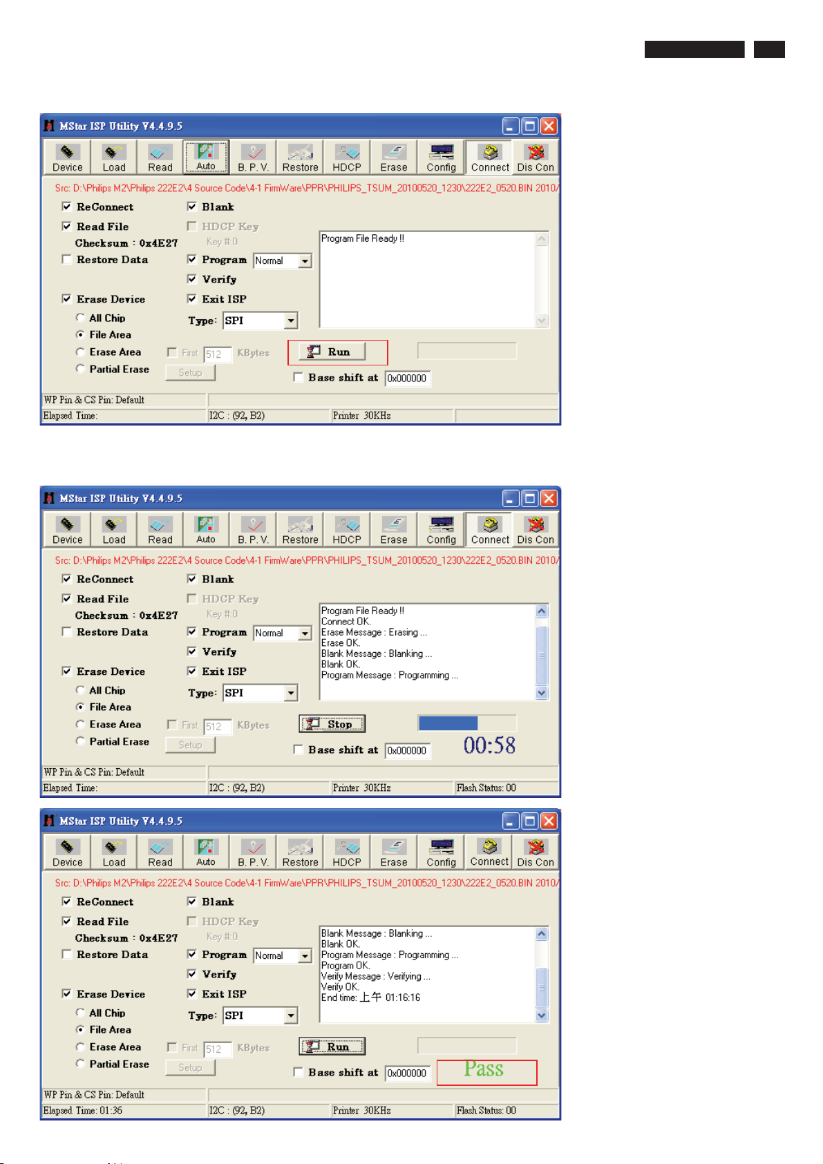
Step 5: Choose Option “Auto”, then press “Run”
Step 6: Choose Option “Auto”, and then press “Run”; the firmware will upgrade complete after the message
shows “PASS”
Page 36
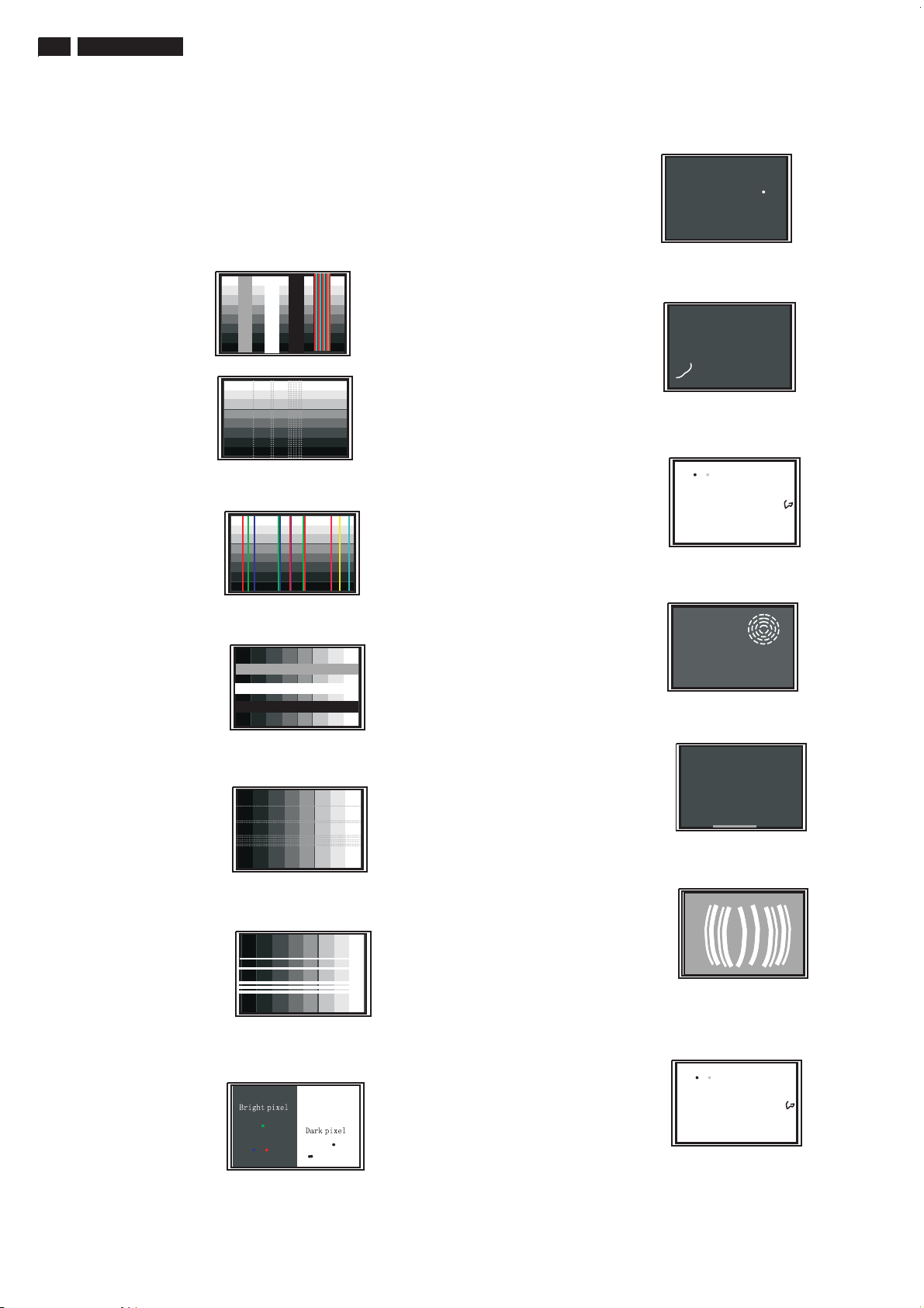
36 222EL2 LCD
Failure Mode Of Panel
Quick reference for failure mode of LCD panel
this page presents problems that could be made by LCD panel.
It is not necessary to repair circuit board. Simply follow the mechanical
instruction on this manual to eliminate failure by replace LCD panel.
Polarizer has bubbles
Failure description
Vertical block defect
Vertical dim lines
Vertical lines defect
(Always bright or dark)
Horizontal block defect
Phenomenon
Polarizer has bubbles
Foreign material inside
polarizer . It shows liner or
dot shape.
Concentric circle formed
Horizontal dim lines
Horizontal lines defect
(Always bright or dark)
Has bright or dark pixel
Bottom back light of LCD is
brighter than normal
Back light un-uniformity
Backlight has foreign material.
Black or white color, liner or
circular type
Page 37

222EL2 LCD 37
:LULQJ'LDJUDP
Page 38
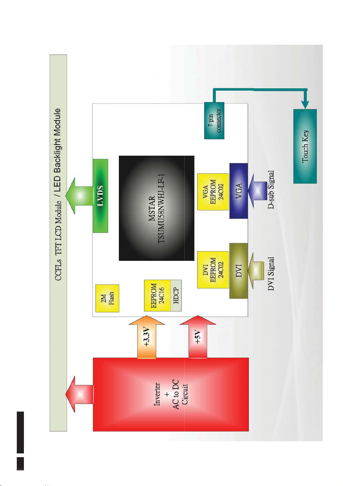
%ORFN'LDJUDP
38 222EL2 LCD
Page 39
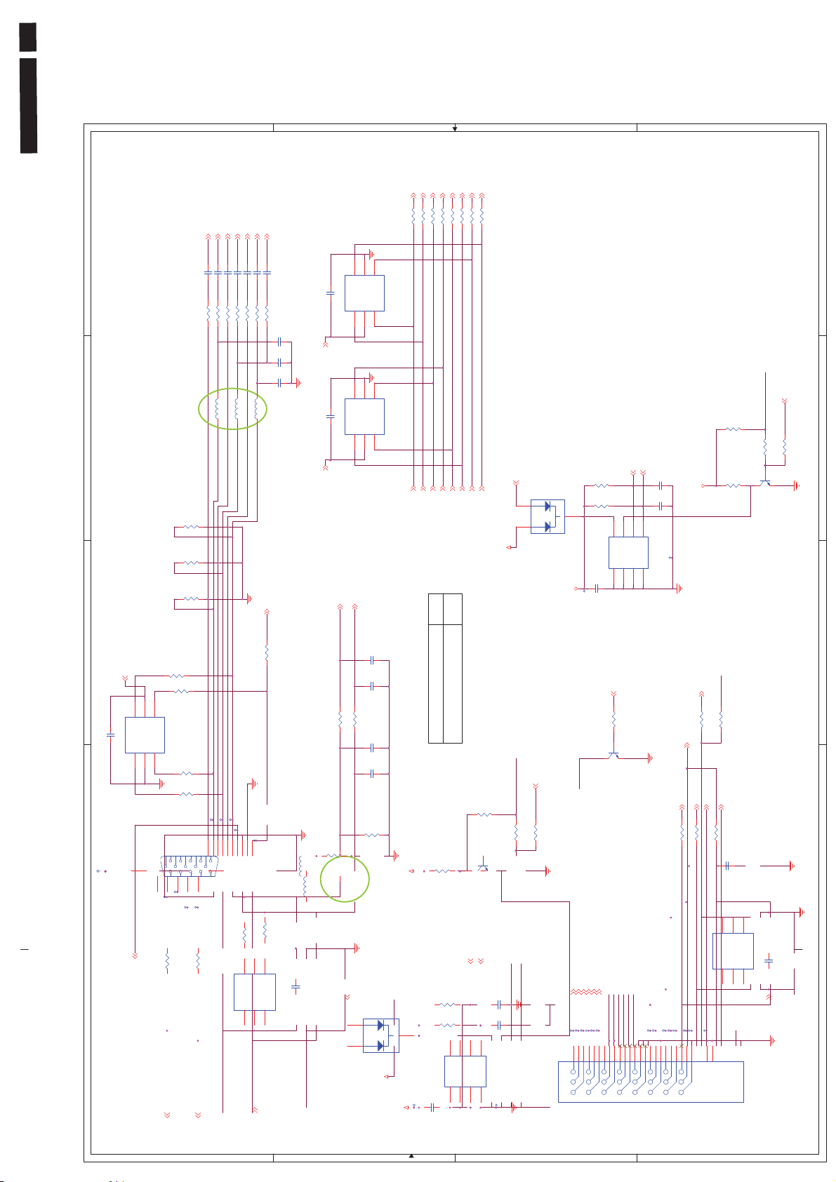
222EL2 LCD 39
A
RED-
RED+
GREEN+
GREEN-
BLUE-
BLUE+
5
C4 0.01U K
C2 0.01U K
C3 0.01U K
56 F
100 F
100 F
R5
R4
R7
R+
Z60
L1
SOG
C5 0.01U K
C6 0.01U K
C8 1000PK
C7 0.01U K
56 F
56 F
470
100 F
R8
R11
R14
R9
C11
C10
G+
B+
C9
Z60
Z60
L3
L2
C14
NC 4.7P C
DVI_P C 5VDVI_P C 5V
NC 4.7P C
NC 4.7P C
C13
4
GND
R3
75 J
R2
75 J
R1
75 J
Cable_detect_A
B
RX0M
RX0P
RX1M
10
10
10
10
R19
R20
R21
R22
2
3
I/O 11GND
I/O 2
NC 0.1U K
I/O 34VDD5I/O 4
U4
NC 0.1U K
U3
HSY NC
3
I/O 2
I/O 34VDD5I/O 4
VSYNC
AZC099-04S
6
2
I/O 11GND
AZC099-04S
6
RX0+
RX1-
RX0-
,
RXCP
RX2P
RXCM
RX2M
RX1P
10
10
10
10
R23
R24
R25
R28
RX2+
RXC+
RX2-
RXC-
RX1+
+3.3V
-.
C
D
5
WE_D
EDID_WP
R42
10K J
4
NC_47K J
47K J
R44
DVI_P C 5V
DN2
BAT54C
A1
A1
J
J
A2
A2
3.3V_DVI
TP13
R34
R33
C22
15K
15K
U6
0.1U K
6
7
8
WP
VCC
A01A12A23GND
DVI_SCL
C24
27P J
3.3V_DVI
C23
27P J
5
SCL
SDA
TP20
AT24C02
4
DVI_S DA
R43
B
R41
10K J
E C
Q3
2N3904S
3
R13
R128
I/O 4
I/O 11GND
100 J
R129
100 J
4
5
VDD
I/O 3
AZC099-04S
I/O 2
2
3
R131
100 J
DSUB _PC5V
6
NC 0.1U K
C1
U1
10K J
WE_A
S c alar Diagram & C .B .A
R130
100 J
TP2
TP4
TP6
TP7
2
TP1
J1
G1G2
1728394105
6
1112131415
TP8
TP9
2K24012A15
TP5
TP3
150 J
150 J
R10
R6
DSUB _PC5V
1
TP10
120
L4
Z
L5
Z120
100 J
R132
U2
2
3
I/O 2
I/O 34VDD5I/O 4
100 J
R133
I/O 11GND
C12
AZC199-04S
NC 0.1U K
6
C18
NC 22P J
C17
NC 22P J
1K J
1K J
R16
R15
C16
22P J
C15
22P J
-
R18
10K J
R17
10K J
3.
DSUB _PC5V
DN1
BAT54C
A1
A1
J
J
A2
A2
+3.3V
3.3V_VGA
!" #$%&'( ) & (& * +
WE_A
EDID_WP
R27
10K J
47K J
NC_47K J
R31
J
B
R26
10K
15K
15K
7
8
WP
VCC
A01A12A23GND
E C
Q1
2N3904S
DSUB _SCL
DSUB _SDA
5
6
SCL
SDA
AT24C02
4
3V_VGA
R30
R29
U5
C19
0.1U K
TP11
R32
C21
27P J
C20
27P J
TP12
TP14
J2
Hot_plug_ctrl
10K J
R35
B
Q2
2N3904S
E C
HP_DE T_DV I
RX1-
RX2+
RX1+
RX0+
RX2-
RX0-
TP18
TP19
TP15
TP16
TP17
9
112233445566778
9
10101111121213131414151516
171718181919202021212222232324
TP21
TP22
TP24
TP23
Cable_detect_D
WE_D
100 J
47 J
R38
R40
DVI_P C 5V
RXC-
DVI_SCL
DVI_SDA
RXC+
4.7K J
150 J
150 J
R39
R36
R37
VI
HP_DE T_D
U7
TP25
TP26
TP27
TP28
16
24
8
G1G1G2
5
1U K
C2
0.
2
3
I/O 11GND
I/O 2
I/O 34VDD5I/O 4
NC 0.1U K
AZC199-04S
C26
6
DVI_P C 5V
G2
2K22009024
3
2
1
DSUB _SCL
DSUB _SDA
A
DSUB _PC5V
B
C
D
Page 40
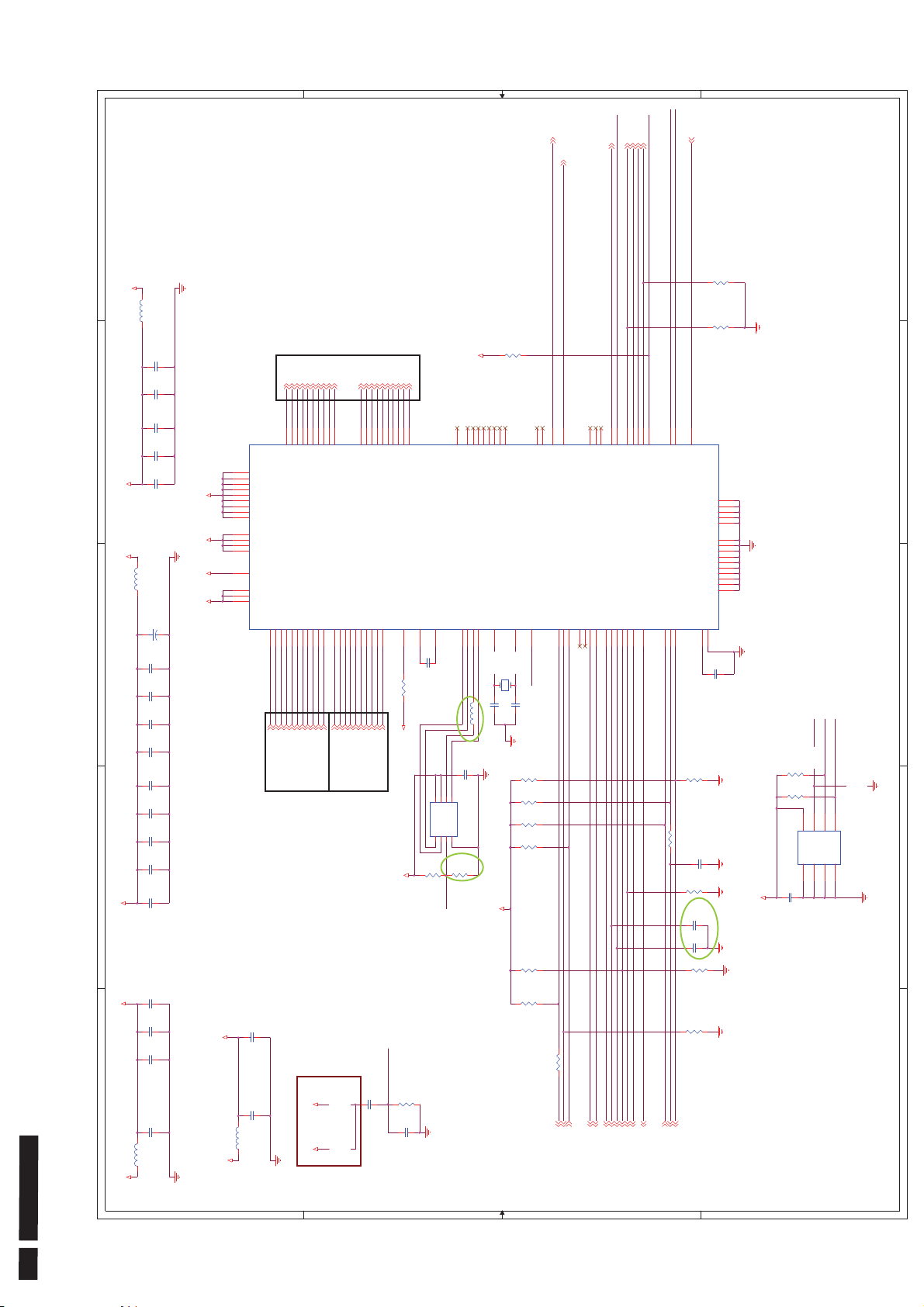
S c alar Diagram & C .B .A
R_PWM
LCD_5V_AWARE
5
+1.8V
L8
Z30
R50
C45
10U M
RXE3-
RXE3+
RXE2-
RXE2+
RXE1-
RXE0+
RXE1+
RXEC+
RXEC-
RXE0-
RXOC-
RXO3+
RXOC+
RXO3-
RXO0+
RXO2-
RXO2+
RXO1+
RXO0-
RXO3-
RXO3+
91
92
LVB3P
RX0P15RX0N16RXCKP18RXCKN
Rx0P
RX0M
RXO2-
RXOC+
RXO1+
RXO2+
RXOC-
95
97
94
96
93
LVB2P
LVB3M
LVB2M
LVBCKP
LVBCKM
DDCD_SDA5DDCD_SC L
6
19
DVI_SDA
RXCM
DVI_SCL
RXCP
RXO1-
RXO0-
RXO1-
RXO0+
99
98
100
LVB1P
LVB0P
LVB1M
LVB0M
TS UMU58NHJ-LF
U8
REXT7REFP31REFM30SDO41SCK43CSZ42SDI
C50
0.1U K
390 F
R46
SPI_DI
AVDD_33
8
7
VDD
HOL D #
CE#1SO2WP#3VSS
U9
+3.3V
R47
NC 100KJ
103
90
VCTRL
C51
6
5
SI
SCK
W25X20AVSNIG
4
R48
10K J
FLASH_WP
To LVDS
C44
4
0.1U K
C43
0.1U K
VDDP
C42
0.1U K
VDDC_18
C41
0.1U K
+3.3V
L7
Z30
C40
47U 25V
+
12
114
VDDP
112
VDDP
107
VDDP
87
VDDP
71
VDDP
59
VDDP_33AVDD_33
VDDC_18AVDD_18
VDDP
58
VDDP
54
VDDP
40
126
104
74
53
21
20
14
8
RXE3-
RXE3+
77
78
LVA3P
VDDC
VDDC
VDDC
VDDC
AVDD_18
AVDD_33
AVDD_33
AVDD_33
RIN0P28GIN0P25SOGIN026BIN0P23RIN0N27GIN0N24BIN0N22HSY NC032VSYNC0
RXE2-
RXE1-
RXEC+
RXE0-
RXE1+
RXE2+
RXE0+
RXEC-
81
83
85
80
82
84
86
79
LVA2P
LVA1P
LVA0P
LVA2M
LVA1M
LVA0M
LVA3M
LVACKP
LVACKM
RX2P9RX2N10RX1P12RX1N
DDCA_SDA/RS232_ T X34DDCA_SC L/RS 232_ R X
33
13
35
3
C39
0.1U K
C38
0.1U K
C37
0.1U K
C36
0.1U K
C35
0.1U K
C34
0.1U K
C33
2
0.1U K
C32
0.1U K
VDDP_33AVDD_33
C31
0.1U K
RED+
GREEN+
GREEN-
RED-
RX2P
RX2M
BLUE+
VSYNC
BLUE-
HSY NC
RX1M
SOG
Ana l og Si gna l
RX1P
DSUB _SDA
DSUB _SCL
Di g i t a l S i gna l
10K J
+3.3V
76
70
73
NC60NC61NC64NC65NC66NC67NC89NC
GPIO_0575GPIO_04
GPIO_06
GPIO_P03/PWM3
XIN
XOUT
RST
GPIO_P12/PWM3
GPIO_P43/PWM0
44
128
127
SPI_CLK
Y1
14.318MHZ
SPI_DO
Z60
C52 33P J
C53 33P J
L10
0.1U K
Fl ash
+3.3V
GPIO_P25/PWM1
108
109
110
111
115
RST
NC 100K J
R58
100K J
R57
R56
10K J
100K J
R55
100K J
R54
EDID_WP
LCD_ON
B_PWM
G_PWM
KEY_POWER
FLASH_WP
57
51
50
48
GPIO_1255GPIO_1356GPIO_14
GPIO_P0447GPIO_P0546GPIO_P41
GPIO_P4249GPIO_P22
GPIO_P27/PWM1
GPIO_P24/PWM2
GPIO_P17/SAR 0
GPIO_P00/SAR 1
GPIO_P01/SAR 2
GPIO_P06
GPIO_P07
GPIO_P02/SAR 3
GPIO_01
GPIO_08
GPIO_09
GPIO_10
116
117
118
GPIO_P26/PWM2
119
120
121
123
124
122
125
USB _detect
NVRA M_S CL
NVRA M_S DA
NVRA M_WP
100K J
R66
NC_100K J
R65
38
36
39
45
GPIO_P23/PWM1
I2C _MCL /GPIO _P1 0
I2C _MDA/G PIO_ P11
GND
113
GND
69
GND
68
GND
63
GND
62
GND
106
GND
105
GND
101
GND
88
GND
72
GND
52
GND
29
GND
17
GND
11
GND
1
MODE
GPIO_P15/PWM03GPIO_P16/PWM2
BYPASS
GPIO_P14/PWM0
4
2
37
102
C57
0.1U K
NVRA M_WP
NVRA M_S CL
NVRA M_S DA
R68
100K J
R63
0J
R60
C56
NC_10U Z
NC_100K J
R62
C55
27P J
C54
27P J
NC_100K J
R64
4.7K J
R67
4.7K J
5
7
8
6
WP
SCL
SDA
VCC
A01A12A23GND
AT24C16AN-10S J-1.8
4
NVRAM
U10
C58
0.1U K
+3.3V
5
4
3
2
40 222EL2 LCD
C30
0.1U K
C29
0.1U K
C28
0.1U K
1
C27
22U M
L6
Z30
+3.3V
C47
0.1U K
AVDD_18
ResetCircuit
C46
22U M
L9
Z30
+1.8V
5V_12V_ panel
+5V_US B+
A A
RST
C48
10U M
R45
10K J
C49
0.22U K
B B
100K J
R53
100K
R61
10K J
R59
1
Pilot_2
Pilot_1
Audio_ADJ
PW5V_SW
Cable_detect_A
PWM3
LED_blu
BL_ON
Key_pw
BRT_ADJ
LED_orag
ADC_KEY1
ADC_KEY2
Audio_ON
Hot_plug_ctrl
Cable_detect_D
PWM0
C C
D D
Page 41
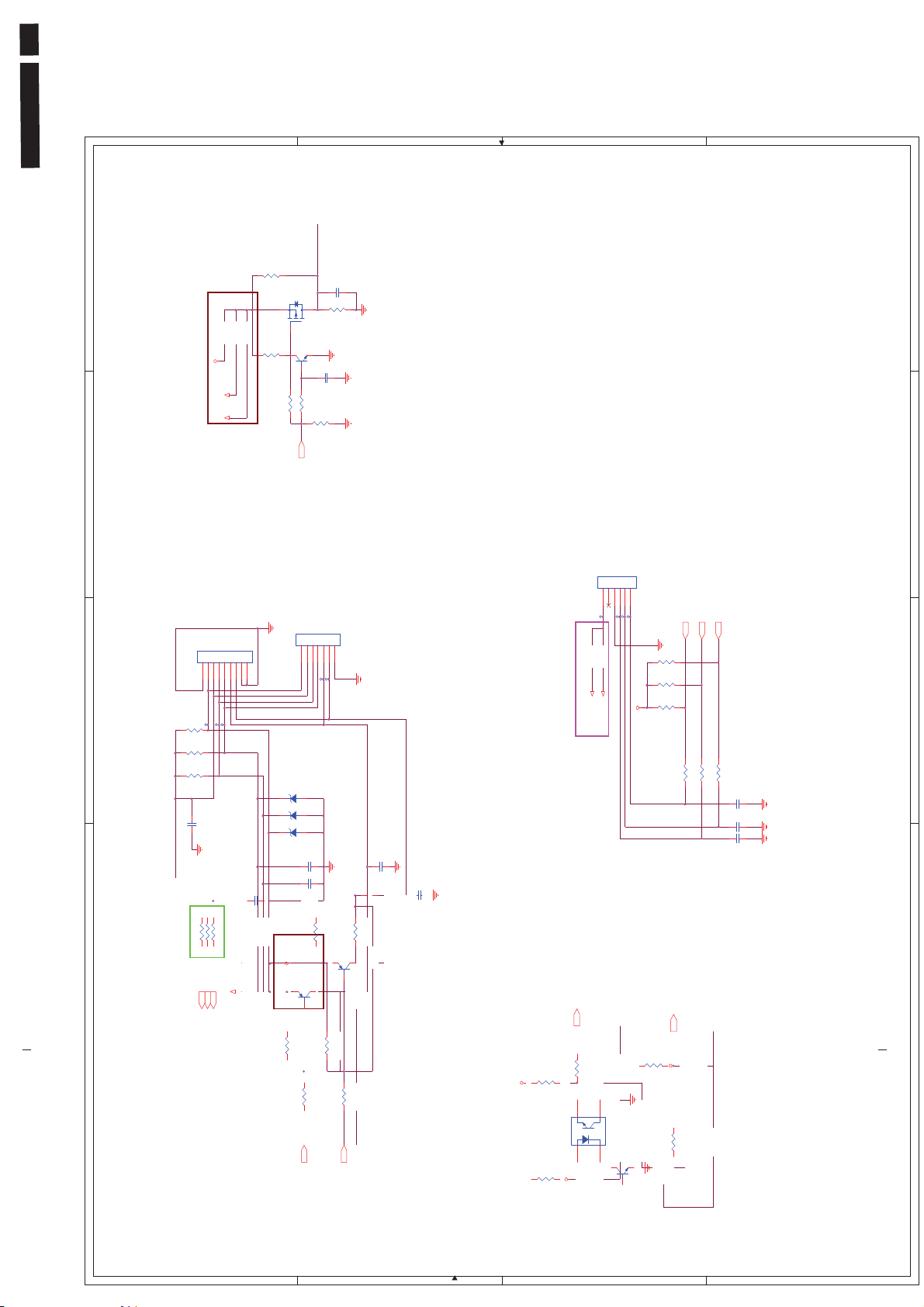
222EL2 LCD 41
A
B
C
D
5
+3.3V
R81
R80
R74 s hort, R75 open
5V_12V_ panel
+5V_US B+
onl y s uppl y +5V_USB on +12V panel
remove R136 and mount R159
Sensor_power
NC_0 J
C64
10U M
Q4
APM2305BAC-TRL
D
S
R87
G
10K J
NC_100 J
R82
100K J
Q5
2N3904S
E C
B
C63
47K J
NC_0.1U Z
R85
R86
10K J
5
AC ON K ey L E D
R141 : 1M J 10K J
NC t o
4
2K K224 1007
G2
3
TP29
R73
10K J
R72
4.7K J
R71
4.7K J
C59 0.1UZ
J3
1234567
G1
TP31
TP30
S c alar Diagram & C .B .A
Sensor_power
sor key
100 J
2
Touch sen
100 J
R77
R78
ADC_KEY1
C60
100 J
R79
5V_12V _panel
+5V_USB+
(ATTN)
ADC_KEY2
Key_pw
KEY_POWER
122
J4
1234567
TP32
TP33
D3
TZMC6V2
A K
A K
D2
TZMC6V2
A K
D1
TZMC6V2
C62
220P J
C61
220P J
220P J
0
R90
Q6
2N3906S
C E
B
1K J
1K J
R88
R91
Hiko 2009. 10. 02
can' t mount J8 i n +12V panel
J5
12345
TP34
NC_2K62095107
+5V_USB+
5V_12V_ panel
ATTN
C65
0.1U Z
C66
Change R127 f rom 0603 t o 0805
Hi ko 2009. 10. 16
R93
0
Q11
2N3906S
C E
NC
B
0.1U Z
Pilot_1
1K J
R99
R96
100K J
For Ergol ight functi on
1. G_PWM i s DAC f uncti on
2. R_PWM and B_PWM i s I / O f unct i on
For I R_1 functi on
1. G_PWM i s DAC f uncti on
2. R_PWM and B_PWMis I2C function
For I R_2 functi on
1. R_PWM i s I / O f uncti on
6
2K 62095106
TP35
TP36
TP37
R102
NC_4.7K J
R101
4.7K J
+3.3V
R100
NC_4.7K J
4.7K J
R103
Pilot_2
R104
NC/100K J
+3.3V
2. G_PWM and B_PWM i s I 2C f unct i on
37
38
124
38
R_PWM
G_PWM
B_PWM
C99/R14 7 : G_PWMIRAdj
R148 : B_PWM Pres ent out
C101 / R1 4 6 : R_PWMIR_ON
1K J
4.7K J
R105
R107
C69
1U K
C68
NC_0.1U Z
C67
1U K
4
3
2
R89
4.7K J
R92
4.7K J
LED_ORG
LED_BLU
1
mo u n t R 1 5 7
un- mount R158 on +12V panel
LED_orag
LED_BLU
67
A
B
R95
160
+3.3V +3. 3V
C
E
E
C
SW1
AAK
2B46001001
K
Q7
2N3904S
E C
B
C
1K J
R106
1
D
Page 42
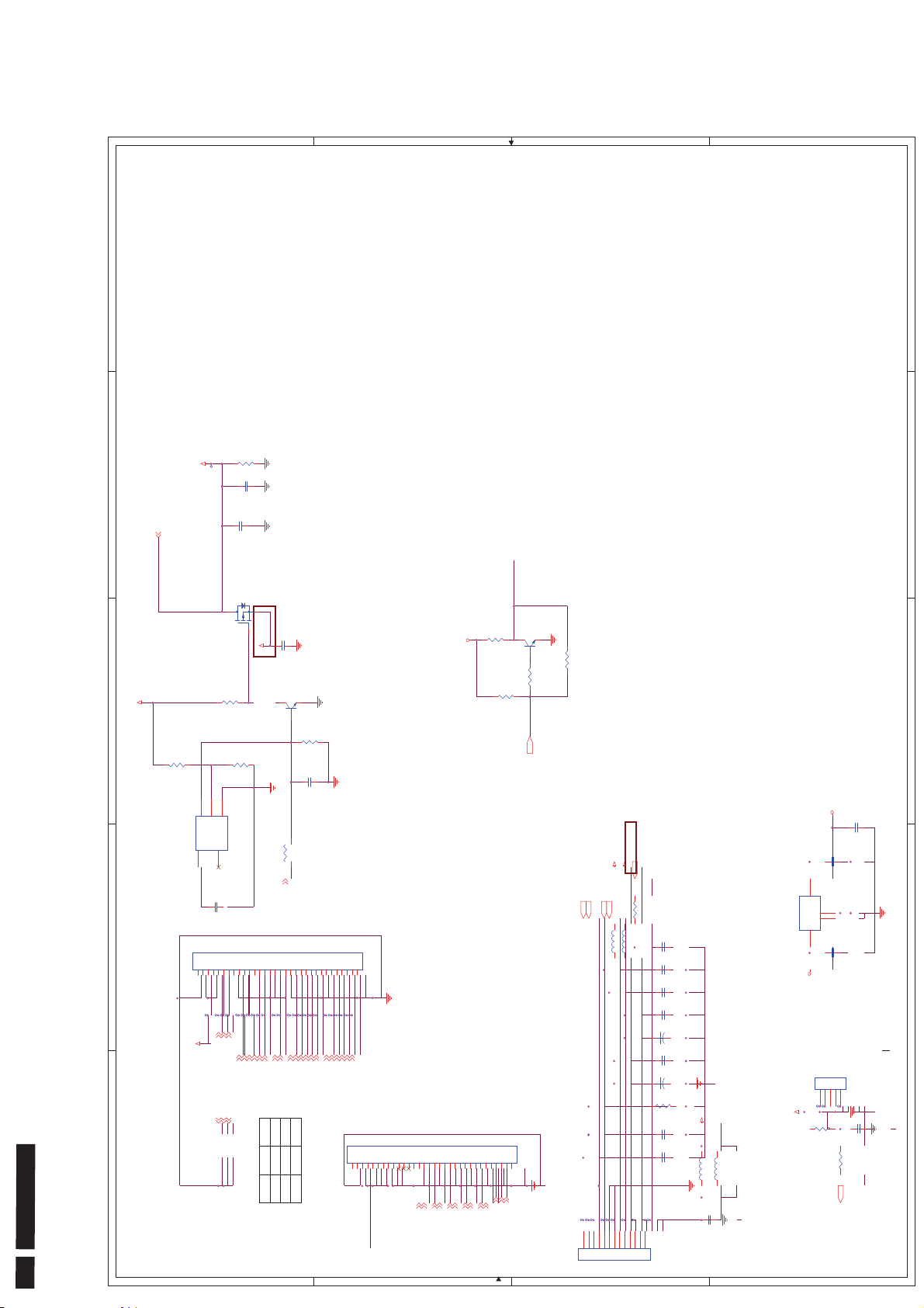
A
B
C
D
9J.
5
R114
220 J
C72
TP39
C71
Q8
DGS
R111
100K J
NC_20K J
R113
0.1U K
10U M
AO 3401L
C73
0.1U K
5V_12V_panel
Q9
2N3904S
E C
+3.3V
B
R117
10K J
C74
10U M
INV_ON/OFF
NC_2N3904S
Q10
E C
R118
NC_4.7K J
R119
NC_10K J
1K J
B
R123
R120
NC_10K J
BL_ON
BL_ON
4
5V_12V_panel
3
LCD_POWER
LCD_5V_AWARE
NC_0 J
R108
5
4
3
42 222EL2 LCD
S c alar Diagram & C .B .A
3
2
1
VCC
GND
/RESET
C_G697L483T 1UF
CD5NC
U11
N
7D.00697 .E3B
4
C70
NC_47P J
20K
118
R116
LCD_ON
110
103
Audio_ON
INV_ON/OFF
BRT_ADJ
2
J6
112233445566778899101011111212131314141515161617171818191920
G1
G1
To Panel
TP38
TP40
TP41
TP42
TP43
TP44
TP45
TP46
TP47
LCD_POWE R
RES1_GND
RES2_GND
RES3_GND
RXEC-
RXE3+
RXE3-
RXEC+
RXE2+
RES1_GND
RES2_GND
RES3_GND
1
21212222232324242525262627272828292930
20
TP51
TP52
TP53
TP54
TP48
TP55
TP49
TP50
RXE2-
RXE1+
RXE1-
RXE0+
RXE0-
RXO3+
RXO3-
LG SEC
R100 NC
R101 NC
R103 NC
A
G2
2K K2085030
30
G2
TP59
TP60
TP62
TP61
TP56
TP57
TP58
RXOC-
RXOC+
RXO2+
RXO2-
RXO1+
RXO1-
RXO0-
RXO0+
N/C_J7
112233445566778899101011111212131314141515161617171818191920
G1
G1
TP63
TP66
TP64
TP65
RXE1+
RXE1-
RXE0-
RXE0+
RES1_GND
RES2_GND
RES3_GND
12345678910111213
To Power BD
J8
C
Fo r S ingle ChannelLVDS
G2
2K K2254030
30
G2
21212222232324242525262627272828292930
20
RXE3-
RXE2-
RXE2+
RXE3+
RXEC-
LCD_POWE R
RXEC+
B
_SW
V_panel
PW5V
+3.3V
5V_12
124
Audio_ADJ
1K J
Z220
Z30
R121
L12
L11
C83
0.1U K
C82
0.1U K
C81
1U K
C80
0.1U K
+
12
C76
47U 25V
C79
0.1U K
+
12
C75
47U 16V
+5V_USB+
R122
NC_10K J
C78
1U K
C77
NC_0. 1U K
TP67
TP71
TP68
TP70
TP69
2K61185113
Z30
Z30
L14
L13
C84
0.1U K
+ 5 V _ U S B + t r a c e w i d t h mu s t b e mo r e t h a n 2 mm
+1.8V
C87
0.1U Z
M
C86
10U
3
OUT
TAB
RM2101B0DA
4
GND
2
IN
U12
1
C85
0.1U K
+3.3V
J9
12345
TP72
TP73
+5V_USB+
R124
1K J
NC_10K J
R125
36
2
2K62095105
TP74
C88
NC_0.1U Z
1
USB _detect
D
Page 43
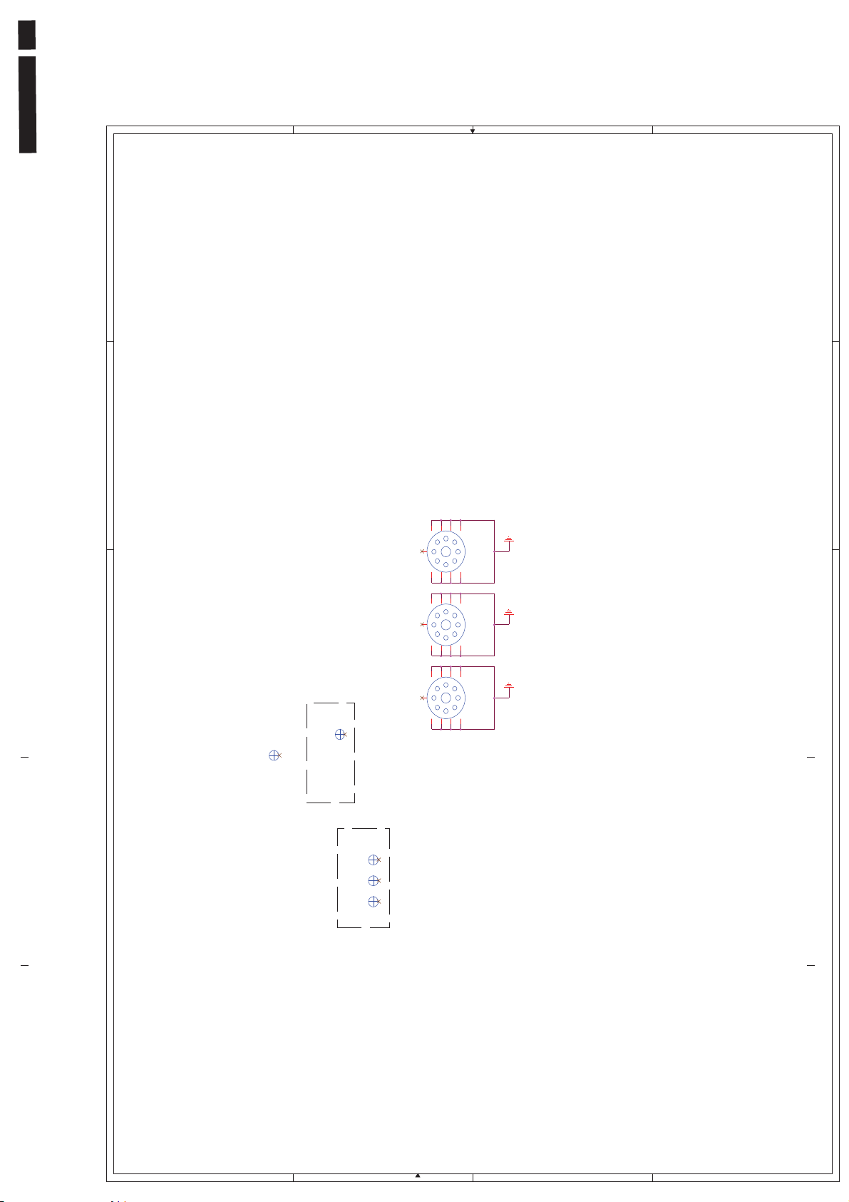
222EL2 LCD 43
A
B
C
D
5
4
678
9
1
234
5
H3
HOLE-V8
678
9
1
234
5
3
|4.5fi
S cr ew Holes
H4
HOLE-V8
5
4
3
678
9
1
234
5
H5
HOLE-V8
OP
H2
OP
H1
S c alar Diagram & C .B .A
2
OP
OP3
OP
OP2
Opt i c al Po i nts
OP
OP1
1
2
1
A
B
C
D
Page 44
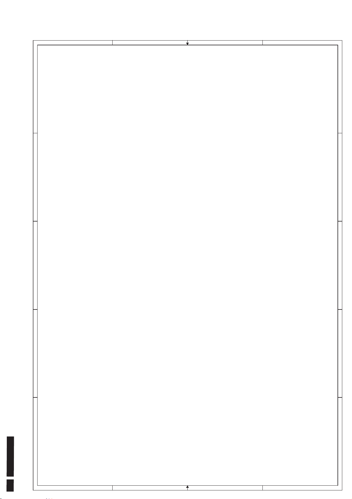
1
1
S c alar Diagram & C .B .A
2
3
2
3
44 222EL2 LCD
4
1. R74 shor t , R75 open
2. R 9 0 75ohm t o 0 ohm
3. Pi n70 t o LCD_5V_AWARE
4 . L ED_ BL U/ Key _pw c hange
5. c hange C75/ C76 f r om 0J . 47612. 089 t o 0J . 4761D. 20V
6. Change C40 f r om 0J . 22612. 21B t o 0J . 4761D. 20V
7. C1 5/ 16/ 17/ 18 27p t o 22p
8. Us e SMD t y pe f or S i ngl e c hannel L VDS
5
D D
C C
B B
A A
4
5
Page 45
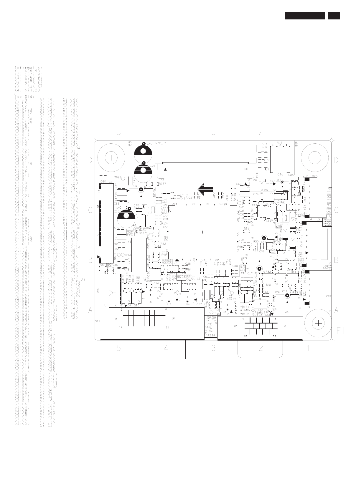
S c alar Diagram & C .B .A
222EL2 LCD 45
Page 46
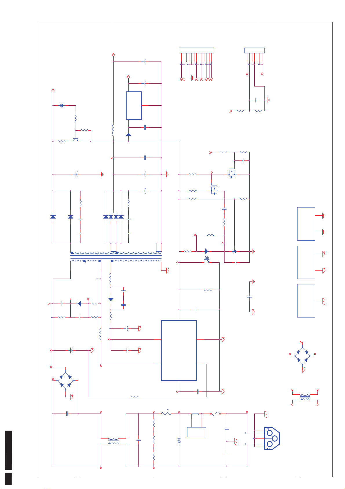
4
3
2
1
Power Diagram & C.B .A
+5V
C705
+
12
CN701
330U 35V
123456789
2K61185113
101112
13
CN702
1234567
2K61185107
1
3.3V
C715
470U 10V M
+
17V
ZD701
BZV55-C 18
A K
R717
330
R718
10K F
B
R716
100 2W
2
A K
D705 UG4D-E 3/73
E C
Q703
KT C 200-Y/P
C713
330U 35V
+
12
R715
27
C712
1000P K
A K
D704 UG4D-E 3/73
C711
1000P K
3
T601
C606
E3
0.001U J
R604
68K 2W
TP605
4
E2
E1
12
1
+
N4
~
2
-
4
C602
3
1 10
TP606
E4
C605
+
BD601
0.33U
E5
D601
UF4007-LF
R610
47
A K
N. C .
C607
100P J
R609
47
L603
150U 450V
600V 2A
2KBP06M-LF
~
3
Z45/100MHZ
L701
2.7U
D701_J
D701
FMX-12SL
A K
A K
A1JA2
D703 UG4D-E 3/73
8
9
4
2
L604
Z45/100MHZ
AK
D602
UF4007-LF
R606
0
TP604
12
IC601-Vcc
E6
L4
5
1
4
2
3
L601
20MH
12
3
VOUT
GND
2
VIN
IC7 02
RM2101D0BA
1
C714
R701
C702
C701
R608
C601
UF4007-LF
27
1000P K
1000P K
0.68 2W
0.33U
C706
C704
+
12
C703
+
12
0.1U K
0.1U K
330U 35V
330U 35V
7
4
IC601
1
L3
21
R601
R602
R603
65
ER -2828 600UH
VCC
D/ST
TR 601
2M
NTC 8OHM
2M
2M
D706
A K
D702 UG4D-E 3/73
C613
220P J
C612
220P J
C608
22U 50V
+
C609
0.1U K
TP713
TP711
TP712
BRT_ADJ
BLT_ON
TP716
TP718
TP717
TP714
TP715
3.3V
+5V
MUTE
VOL_ADJ
PWR_SAV
BLT_ ON
TP708
TP709
17V
BRT_A DJ
C717
2.2U K
R721
330
10K
R722
S03:
10K
R713
330
R714
PWR_S AV
G
Q701_G
R711
100K
R710
36K F
R706
10K F
IC6 02_1
R705
470
12
IC601_6
6
FB/OLP
STR-W6262
FM/S S/Latch
7
P01
L2
t
2
.
.
470V
VAR1
1
43
IC602
R607
C611
1000P 50V
GND
5
S/OCP
3
C610
0.01U K
JW1
Jump-Wire
3
1
L
N
N. C .
CN602
2K61007103
Q702
G
Q701
D
S
C707
0.1U K
10K
R709
R708
1K
IC702_K
LTV -817M-L
82K F
F601
250V 2A
C709
2N7002K
D
0.1U K
S
APM2307AC -TR L
R707
10K F
2
G2
HS2
R
IC7 01
LM431BC Z
A K
HS1
C708
4.7U K
C615
3300P M
L1
G
C603
1000PF
TP601
TP602
C604
1000PF
4
L
1
G
2
N
TP603
3
G
5
I C601GND P AD D70 1
GC1
N4
~
2
N3 L4
CN601
3DL0Y01001
3D0W801002
3D05402001
1
E1
-
4
L602
1
2
1
HSi n k
G1
2
G2
1
HSi n k
G1
1
G1
HSi n k
+
BD602
GS IB4A60-LF
L4
~
3
OPEN
4
3
N1 L3
46 222EL2 LCD
D D
N3
N1
C C
B B
A A
Page 47
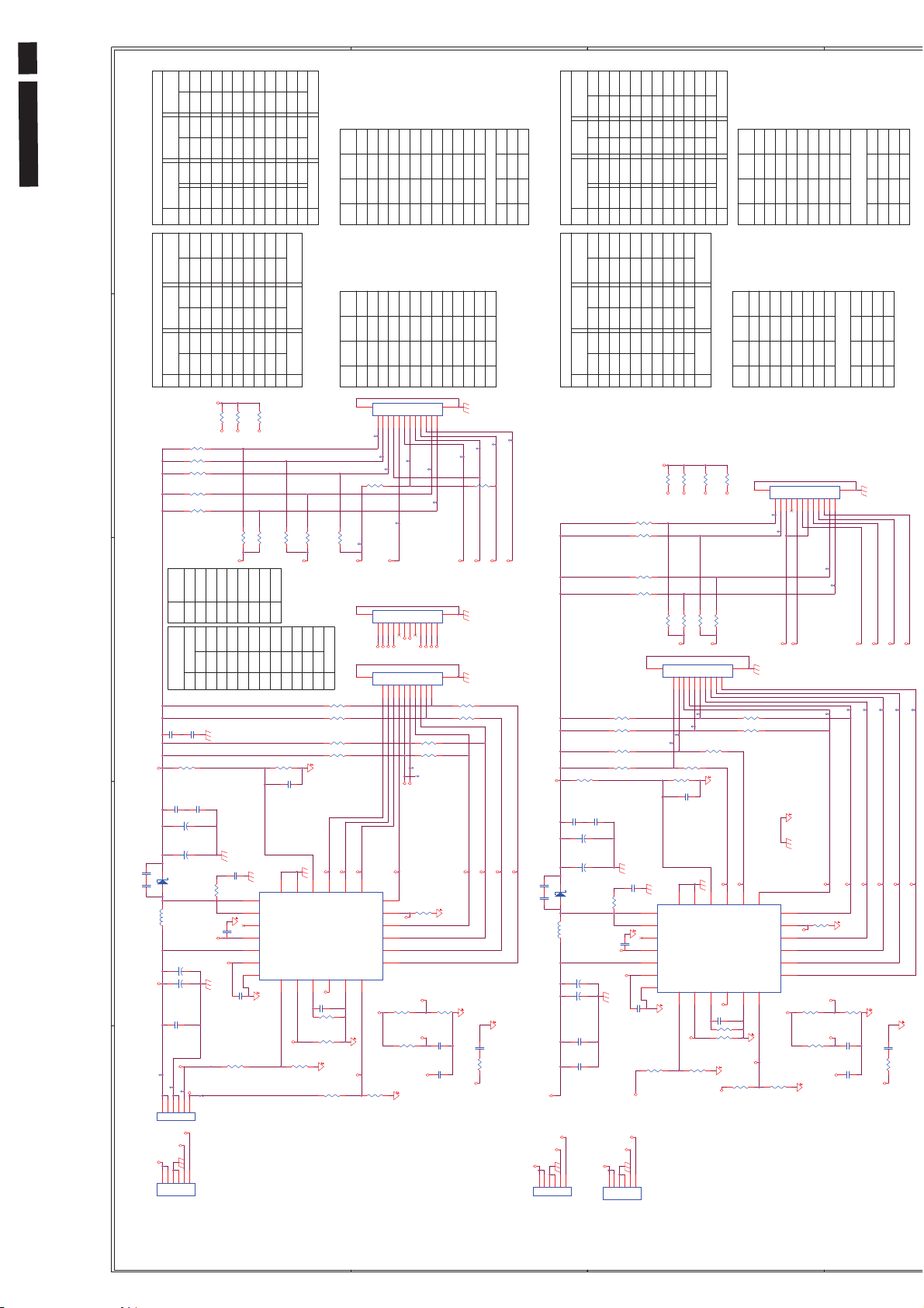
47
222EL2 LCD
10pi n 12pi n
VOUT
LED Diagram & C.B .A--AUO
C865
330P J
C864
330P J
L891
TP851
5 4 3 2 1
Vin Vin
A K
6
6
CMO 23 . 6
CMO 2 0CPT
CMO 18 . 5
CMO 21 . 5
AUO
C831
SS 16T3
22U M
12
12
TP852
VCC1
LED1
LED
VCC
1
LED8
VCC
LED8
LED
LED8
NC
CMO( NE W)
12pi n
CMO( NE W)
12pi n
0.22U K
R895
C896
0.47UK
+
12
12
+
C893
D891
C892
220U25V
+
+
C891
220U
C801
0.1U 50V
BLT_ON
TP853
BLT_ADJ
BLT_ON
LED8
NC
LED2
LED8
LED
LED
LED8LED
NC
VCC
34567
2
LED6
LED7
NC
VCC
LED7 VCC
LED6
LED
LED7
LED6
LED
LED
2
34567
R809
0
R808
0
R807
0
R806
0
R805
0
R801
R802
LED1
CMO NE W
LED
1
C832
0.22U K
300KF
C897
0.47UK
C894
47U 63V
47U 63V
BLT_ADJ
12345
CN851
2K61185106
12345
2K62285106
LED7
NC
LED7
LED
LED7
LED
LED5
NC
LED5
LED
LED5
LED
Vin
R833
LED1
NC000NC
R804
R803
LED2
LED3
LED
LED
34567
2
10
R824
0.033UK
C899
IC1_22
IC1_24
TP855
(LOCK)
(NC)
(LOCK)
CN853
LED6
LED6
LED7
NC
LED
LED
LED3
LED6
LED
LED
LED
LED7
LED5 LED5 LED5
LED6
NC
LED
LED
LED6
LED5
LED4
LED
LED
LED
LED4
LED
VCC
VCC
LED4
LED
VCC
VCC
0
R838
0
LED8
R827
0
LED1
R812
R811
LED4
NC
LED
VCC
C824
220PF/0805/50V
19
20
21
22
23
24
G1
C898
2.2U K
0
R891
LED1
LED26P* 2
LED4
LED3
LED
LED
LED
LED
LED
LED4
LED
VCC
VCC
VCC
NC
LED2
LED3
LED1
LED4
LED6 LED6
NC
LED
LED
LED
LED
91011
12
8
LED3
LED2
LED1
LED7
LED8
LED
LEDLED2
LED
LED1
LED2
LED3
LED
LED
LED
8P* 2 6P*2
LED3
LED1
LED1
LED8
LED
LED
NC
8910
R837
0
LED7
R825
0
R828
0
LED2
0NCNC
R813
R814
LED6
LED5
LED
VCC
LED
8 NC
91011
R897
7.5K F
C866
100pF
17
SW1
PGND218PGND1
SW2
FAULT
COMP
VIN
VCC
PAD
EN1OSC2FSET3PWMO4GND5PWMI
IC1_2
R892
LED40
LED60
LED70
LED80
LED20
LED30
LED
LED30
NC
LED30
LED
VCC
VCC
R857
0
R858
0
R856
0
R855
0
2.2U K
R884
2K62285106
LED
LED40
LED50 LED50
LED
LED
NC
VCC
NC
NC
LED20
LED30
LED40
LED
LED
LED
LED40
LED20
LED30
LED
LED
LED
Vin
R871
0
LED10
R877
0
LED10
CN862
G2
G2
10
TP822
TP821
R886
SW1
19
SW2
20
FAULT
21
COMP
22
VIN
23
VCC
24
PAD
G1
0
CN854
LED30
VCC
VCC
NCNCNC
7P* 2
8P* 17P* 2
23. 618. 5
20
LED10
LED20
LED30
LED80 LED40
LED
LED
LED
12
12pi n
LED10
LED20
VCC
LED10
8P* 2 6P* 2
LED
LED10
NC
10
R879
0
LED80
R875
0
77889910
6
TP830
TP829
R863
0
7.5K F
C888
100pF
17
PGND218PGND1
EN1OSC2FSET3PWMO4GND5PWMI
IC2_2
CMO21.5
CPT10pi n
LED10
LED80
AUO
6P* 2
R872
0
R874
0
LED20
LED40
R876
0
R878
0
LED20
G1
G1
11223344556
R864
0
LED10
LED20
16
OVP
LED115LED214LED3
IC852
MP3388
IC2_4
C863
100pF
R887
0
R839
R882
0
R883
20K J
BLT_ADJ
NC
NC
NC
0
0
NC
0
R855
NC
NC
0
0
0
0
R852
R851
G2
NC
0
NC
0
0
NC
R856
R857
0
0
NC
NC
NC
R854
R853
CN872
G2
12
TP834
TP833
LED30
0
NC
NC
0NC0
0
NC
0
NC
0
NC
R875
R876
R858
0
NC
NC
R861
LED40
R878
R877
NC
0
NC
0
0
NC
0
0
0
NC
R862
7788991010111112
6
0
R864
R863
R871
G1
G1
11223344556
TP832
TP831
LED50
0
R874
R872
R879
R871 0
0
0
R879
R872
R874
CMO
LED60
LED70
LED80
AUO & CPT
TP828
R862
0
0
R861
13
LED4
12
ISET
11
LED5
10
LED6
9
LED7
8
LED8
7
6
100K
IC2_24
IC2_6
R881
20K J
TP824
TP823
LED30
LED40
R888
60.4K F
LED_SET2
IC2_4IC 2_2
R845
10K
C876
R33
100K
IC2_6
C875
TP827
TP826
TP825
LED50
LED60
LED70
LED80
R832
10K
1000P J
C877
0.22UF K
R836
1K J
1000P J
IC2_22
LED10
7P* 2
NC
0
NC00
NC
R808
R807
0
0
NCNCNC
NC
R803
R804
CN871
G2
TP807
TP810
TP808
LED4
G2
LED3
LED2
LED4
G2
77889910
10
LED4
LED4
12
ISET
11
LED_SET1
LED5
10
LED6
9
LED7
8
LED8
7
R821
10K
R873
20K J
0
NC
R809
7788991010111112
7788991010111112
VCC_C MO
6
VCC_C MO
100K
0
NC
R825
0
NCNC0
R811
6
6
VCC_C MO
VCC_C MO
LED5
TP814
R869
IC1_4IC 1_2
IC1_6
NC
00NCNCNC
0
NC
R827
R826NCR828
NC
0
0
NC
R812
R813
TP806
TP805
LED8
LED7
LED6
11223344556
R812
R811
TP813
60.4K F
C873
C871
0
000
NC
0
NC NC
0
0
R829
NC
00
R831
R830
R833
R838
0
0
0
0
00
R814
R833
R838
R837
G1
G1
11223344556
TP801
TP802
TP803
TP804
R831
0
LED7
LED5
G1
G1
11223344556
G1
G1
0
0
R822
10K
1000P J
1000P J
LED8
LED6
CMO
AUO & CPT
R814
0
R813
0
LED6
LED7
LED5
LED8
C872
0.22UF K
R823
1K J
IC1_22
R837
CMO
C868
C867
Vin
00NCNCNC
23. 6
8P* 1
NC
20
LE D8 LE D8
18. 5
7P* 2
R806
R805 NC
12pi n
NC
NC
CMO21.5
0
0
CPTAUO
00NC
R801
R802
10pi n
G2
12
TP811
TP809
R830
0
R829
0
R826
0
TP812
LED3
G2
CN881
R804
0
R803
0
R802
0
R801
0
LED2
LED3
LED115LED214LED3
R896
100K
IC1_6
0
12
LED1
CN861
G2
13
6
IC1_24
R894
LED7
LED8
8P* 1
LED
LED
12
LED1
16
OVP
IC851
MP3388
IC1_4
C890
100pF
0
R835
20K J
R893
CMO 23 . 6
CMO 18 . 5
LED
VCC
LED
LED
LED80
VCCNCLED
LED
LED
LED60
LED70
LED
1234567891011
LED80
LED70
LED60
LED50
LED40
LED
LED
LED
LED
CMO 21 . 5
CPT
10pi n 12pi n
AUO
VOUT
R859
300KF
C886
0.47UK
+
12
C885
12
+
C883
330P J
330P J
6
47U 63V
D881
SS 16T3
A K
L881
22U M
C882
220U25V
+
12
12
+
C881
220U
C811
0.1U 50V
C821
0.1U 50V
Vin
BLT_ADJ
BLT_ON
12345
CN852
2K61185106
LED
LED70
LED60
LED50
LED80
VCC
LED
LED
LED
LED
LED50
LED60
LED80
LED70
VCC
LED
LED
LED
NC
123456789
R852
0
R851
0
R854
0
R853
0
C887
0.47UK
47U 63V
C834
220PF/0805/50V
R834
10
0.033UK
C862
IC2_22
IC2_24
C861
BLT_ON
BLT_ADJ
BLT_ON
Vin
12345
6
D D
C C
B B
Page 48
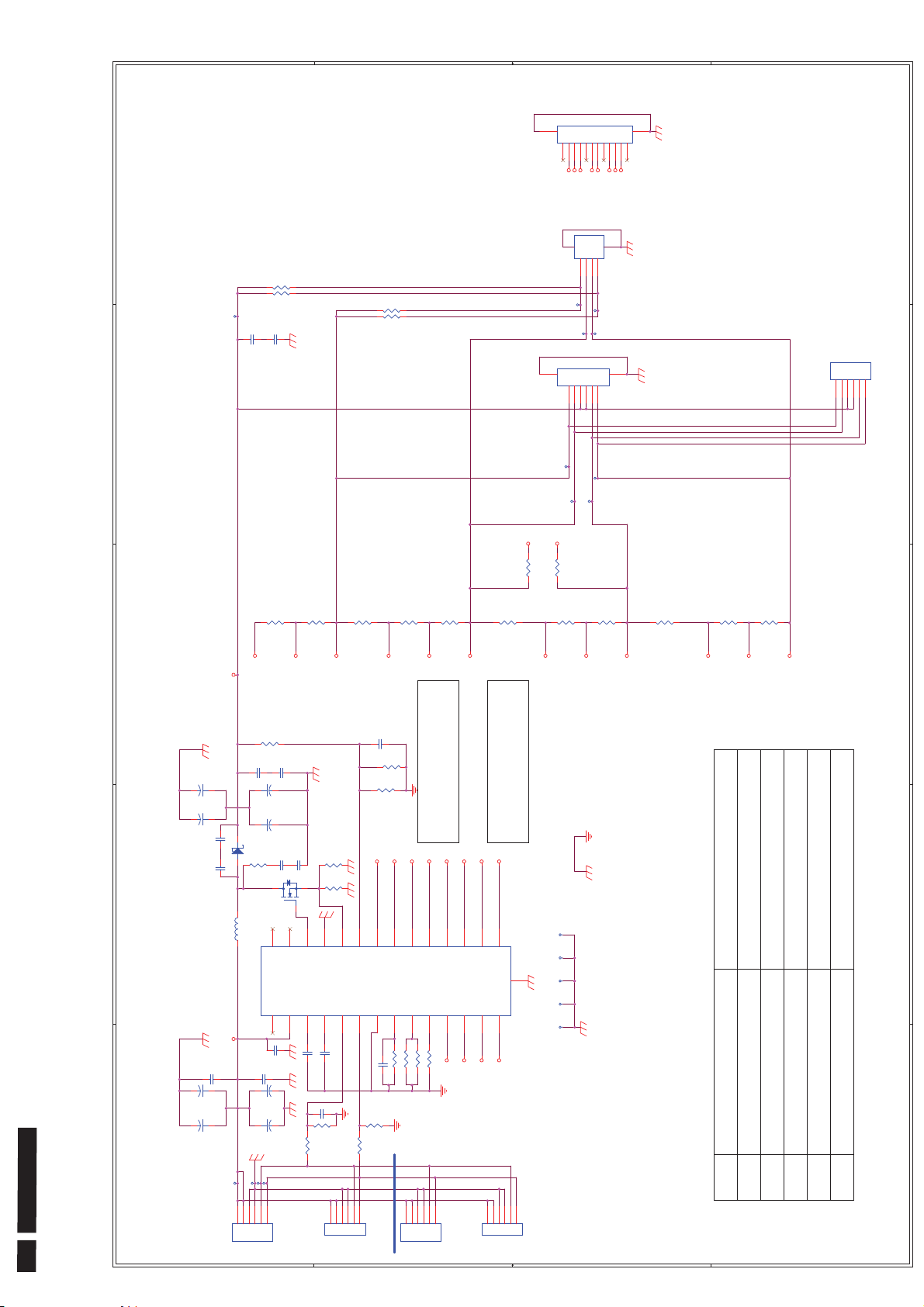
G2
G2
12
CN862
G1
G1
11223344556
7788991010111112
6
CMO
1
CN865
R833
0F
Vout P I N
0F
R835
TP865
(NC)
(NC)
C837
2.2U 50V
C838
2.2U 50V
2
Vout P I N
R893
0F
0F
R895
G1
CN864
2KK2231006
2KK2241004
LED7
LED10
G2
4
TP859
TP861
G1
11223344556
TP855
TP856
Vout
Vout
LED1
LED4
LED5
LED11
G1G1G2
1122334
TP860
TP862
G2
G2
6
TP858
TP857
LG_21. 5
2S LED01- 06 L ED07- 12
3S LED01- 04 L ED05-07 LED0 9- 12
CN868
12345
LG_23
AUO&SE C
6
1
2K62285106
2
CN864( 0. 5mm) &CN865(1mm) & CN868( 1. 25mm )
Vin
Vin
0F
0F
R840
PI N2 NC
R870
R890
R810
0F
R811
0F
0F
R889
0F
R878
0F
R867
0F
PI N5 NC
R834
R856
0F
R845
0F
0F
R823
0F
R812
0F
48 222EL2 LCD
3
LED Diagram & C.B .A--CMO
4
5
Vout
LED12
R836
300K F
C856
0.47U K
C855
C853
47U 63V
+
+
C854
C832
C831
0.47U K
C851
+
A K
12
12
SS16T3
R876
10U M
IC8 51
47U 63V
+
C876
330P J
10
D
Q876
TM3055-TL -E
28
NC
NC1VIN2VCC3COMP
27
1 2
47U 63V
1 2
330P J
D831
330P J
L831
Vin
C833
2.2U 50V
C804
C814
0.1U 50V
+
1 2
C805
220U
+
1 2
C802
220U
TP854
D D
0.1U 50V
+
12
C803
220U 25V
+
12
C801
220U 25V
TP852
TP853
TP851
12345
6
CN851
2K62285106
LED11
C852
47U 63V
C878
330P J
G
VFAULT
(NC)
(LOCK)
LED10
R864
0.33 F
R894
0.33 F
S
26
24
25
GATE
PGND
4
5
C873 0.47U K
C863 0.068U K
R855
20K J
1K
R865
6
LED9
LED8
LED7
C893
100P J
(6.19k)(57. 6k)
R883
8.06K F
LG
R873
100K F
100/ / 8. 06=7. 45 8
LED5
LED4
LED3
LED2
LED1
22
23
OVP
ISE NS E
AML CD
( 300+7. 458) / 7. 458 * 1. 17 =4 8. 2V
LED8
LED7
LED6
MP 3 3 8 9
DBRT
EN
6
C858
2.2U K
1K
R875
12345
7
C857
R866
20K J
2K61185106
ISE T9OSC
GND
0.47U K
CN852
BOSC
33.2K
R859
6
(NC)
60.4K F
R869
C C
LED1211LED1112LED1013LED9
10
R850
100K
LED12
12345
CN853
2K62285106
14
LED11
LED10
LED9
6
(NC)
8
(NC)
191K F
R858
(NC)
LED6
LED5
LED4
100/ / 6. 19=5. 82 9
( 300+5. 829) / 5. 829 * 1. 17 =6 1. 38V
TP876
LED815LED716LED617LED518LED419LED320LED221LED1
IC851
TP875
TP873
G1
TP872
TP871
LOCK)
12345
CN854
2K61185106
(
R( K) =1220 / I _LE D( m A)
LG PANEL 41( mi n) 43. 8( t yp) 46. 6( max) I _ L ED 11 0mA 14. 45W RSET=1220/ ( 110/ 3) =33. 27K
SEC PANEL - - - 5 6. 1( t yp) 59. 5( max ) I _L ED 2 52/ 4mA 1 4. 14W RSET=1220/( 63/ 3) =58. 09K - - - >57. 6K 4P17S
B B
LED2
LED3
AML CDLG
LED1
NC
CN868( 2k . 6228 5. 106)
NC
CN864( 2k . k 2231 . 106)
R883 8. 06k( 6D. 8061 5. 551) 6. 19k( 6D. 6191 5. 551)
OUT P UT
R859 33. 2k( 6D. 3322 5. 551) 57. 6k( 6D. 5762 5. 551)
OUT P UT
R870 NC0( 6D. R0005. 5 51)
A A
3
4
5
Page 49
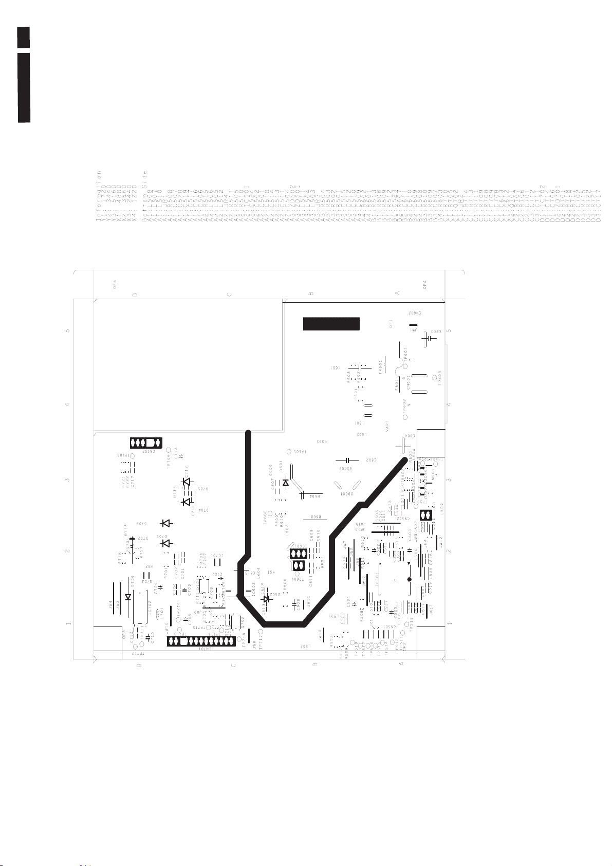
49
222EL2 LCD
Power Diagram & C.B .A
Page 50
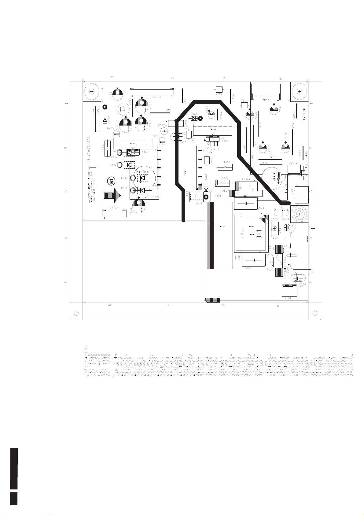
Power Diagram & C.B .A
50 222EL2 LCD
Page 51
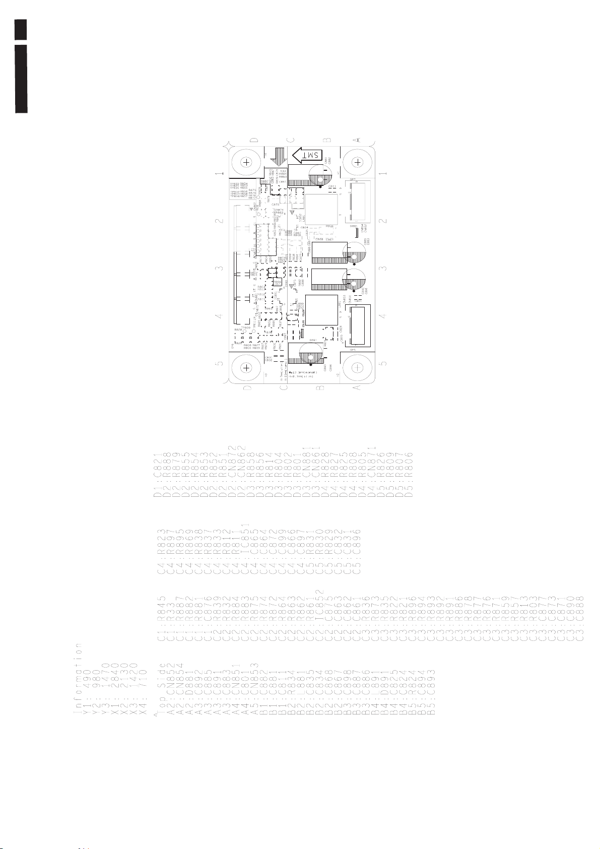
51
222EL2 LCD
LED Diagram & C.B .A--AUO
Page 52
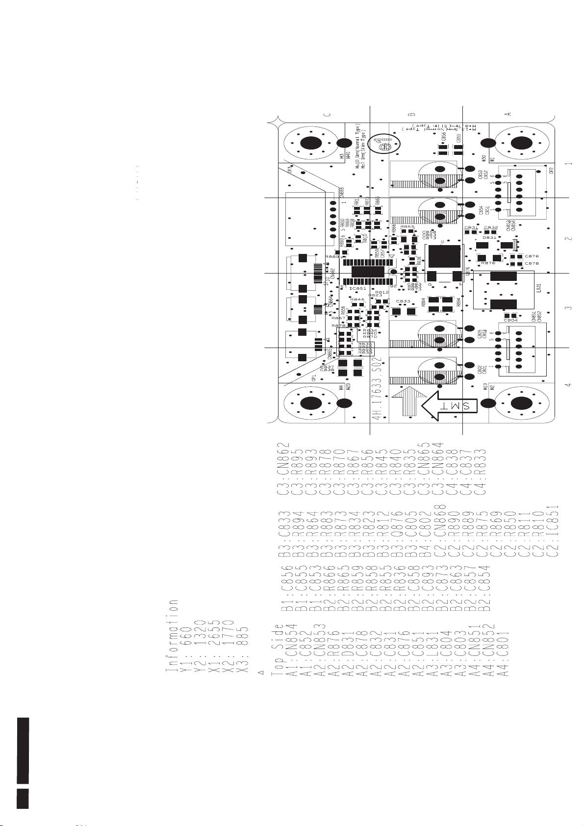
LED Diagram & C.B .A--CMO
52 222EL2 LCD
Page 53
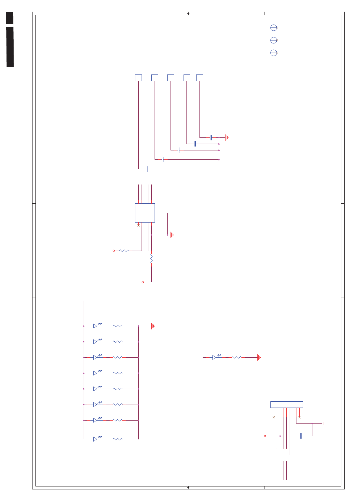
53
222EL2 LCD
>
OP
OP3
OP
OP2
OP
OP1
1
UP
DOWN
ME NU
1
1
1
1
1
1
POWER
BACK
1
1
1
1
1
CS_2
2
C3
NC_15P J
CS_2
CS_3
CS_4
CS_5
CS_6
CS_4
CS_3
C5
C4
NC_ 15P J
CS_6
CS_5
C7
NC_15P J
C6
NC_ 15P J
NC_15P J
2
10
C AP 1 0 06 -1-AIA -TR
CS66CS57CS48CS39CS2
GND
G1
U301
CS11ALE R T2SDAT3SCLK4VDD
5
C2
0.1UK
3
R304
+3.3 V
ATTN
10K J
S ens or_SDA
Sensor_SCL
R12
150
CS2 CS 3 CS4 CS5 CS6
3
+3.3 V
Control Diagram & C.B.A.
4
5
LED_key
AK
Whi t e 2KV
AK
Whi t e 2KV
AK
Whi t e 2KV
AK
Whi t e 2KV
AK
Whi t e 2KV
AK
Whi t e 2KV
AK
Whi t e 2KV
AK
Whi t e 2KV
R8
150
LED8
WHITE
R7
150
LED_pwr
LED7
WHITE
R6
150
LED6
WHITE
R5
150
LED5
WHITE
R4
150
LED4
WHITE
R3
150
LED3
WHITE
R2
150
LED2
WHITE
R1
150
LED1
WHITE
AK
Whi t e 2KV
R13
150
LED9
WHITE
J1
1234567
G1
+3.3 V
#043 121 116 120 123 94
#026 114 114 109 126 94
#039 127 118 124 126 94
4
2KK 2088007
G2
C1
4.7UK
5
LED_pwr
LED_key
ATTN
Sensor_SCL
Sensor_SDA
D D
C C
B B
A A
Page 54
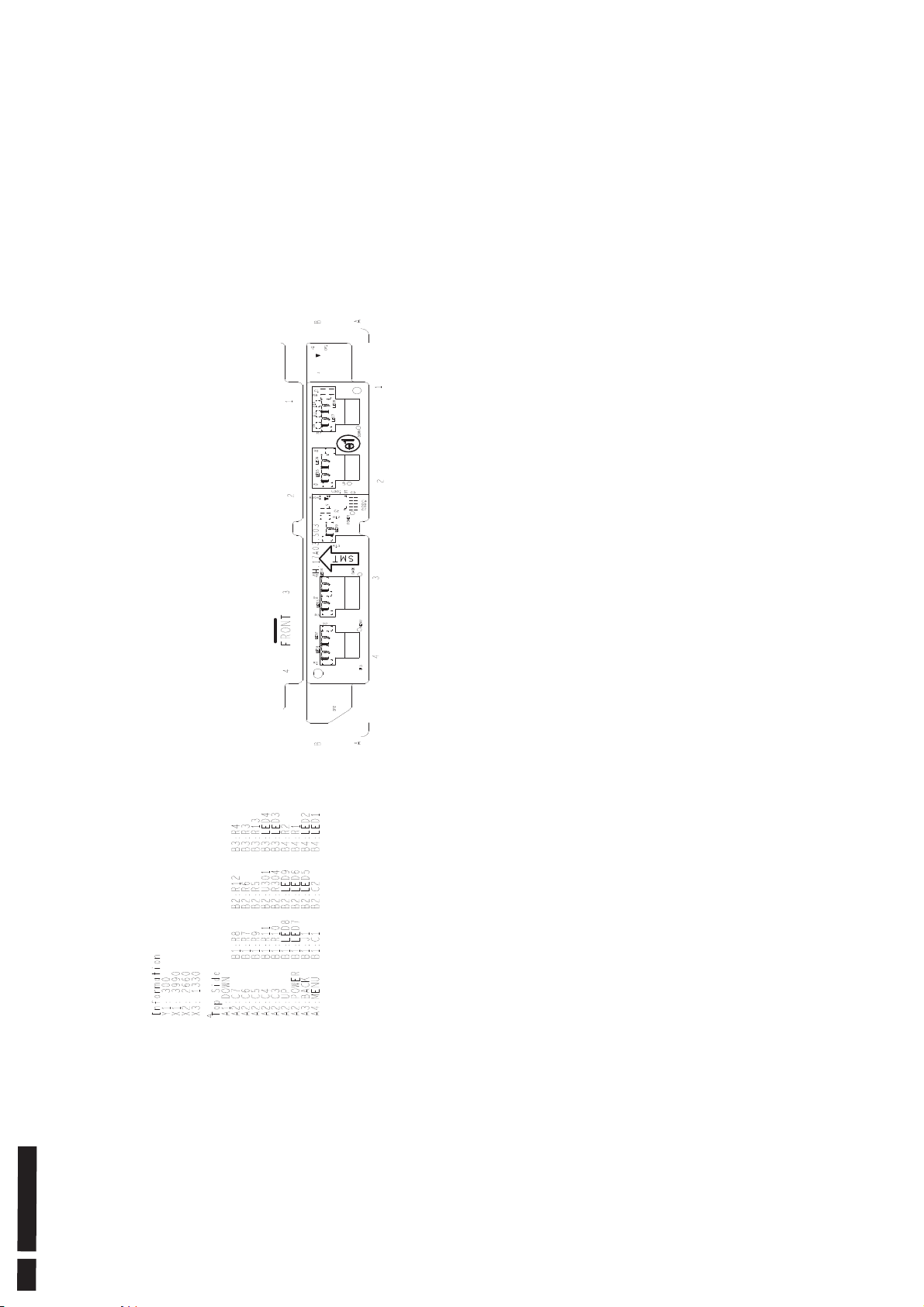
Control Diagram & C.B.A.
54 222EL2 LCD
Page 55
ʳ
ʳʳʳʳʳ
ʳʳʳʳʳʳʳʳʳʳʳʳʳʳʳʳʳʳʳʳʳ˃ˁ˄
ʳ
General Product Specification
Meridian 1- 222EL2
GENERAL PRODUCT
SPECIFICATION
Issued by: Paul Tsai/ Argent Chan
Revision History
Ver. Date (yy.mm.dd) Author Brief Description
0.1 2010.02.05 UC Initiate version
222EL2 LCD 55
Red : pending Philips or INL final conclusion
Blue : agreed changes in this version
222E2 21.5” Wide FHD LCD Monitor
2010/02/05 PHILIPS 1 of 30
ʳ
ʳ
Page 56

ʳ
ʳʳʳʳʳ
ʳʳʳʳʳʳʳʳʳʳʳʳʳʳʳʳʳʳʳʳʳ˃ˁ˄
ʳ
56 222EL2 LCD
General Product Specification
. ANALOG AND DIGITAL INPUT
. AUTO PICTURE ADJUSTMENT
. 12 FACTORY PRESET MODES AND
MODESˈ WHICH CAN BE RECOVERED TO PRESET MODES, 10 USER MODES
ˁʳʳUSER FRIENDLY OSD DISPLAY FOR MODE IDENTIFICATION /ADJUSTMENT
. MAX. RESOLUTION 1920 x 1080 NON-INTERLACED AT 75 HZ
. 23” WIDE COLOR TFT LCD FLAT PANEL
. FULL RANGE POWER SUPPLY 90 – 264 VAC
ˈVGA:46 PRESET MODES ˈDVI 46 PRESET
. CE ENVIRONMENTAL POLICY
. ANTI-GLARE TO REDUCE LIGHT REFLECTION
. POWER MANAGEMENT CAPABILITY
. SOG SUPPORT
. Windows Vista Premium Logo Certification
. HDCP support
. USB PLUG
. SMART CONTROL & SMART MANAGEMENT REQUIREMENT
. SMART Contrast 20M:1
. SMART Image
. SMART Response
. TrueVision (formerly PerfectTuneII or FGA, FACTORY GAMMA ALIGNMENT)
. PHILIPS LOGO displayed while power on
. WEEE REQUIREMENT
. RoHS REQUIREMENT
. TCO05 REQUIREMENT
222E2 21.5” Wide FHD LCD Monitor
2010/02/05 PHILIPS 2 of 30
ʳ
ʳ
Page 57

ʳ
ʳʳʳʳʳ
ʳʳʳʳʳʳʳʳʳʳʳʳʳʳʳʳʳʳʳʳʳ˃ˁ˄
q
ʳ
222EL2 LCD 57
General Product Specification
CONTENTS
1 FOREWORD .....................................................................................................................6
2 PRODUCT PROFILE ........................................................................................................6
2.1 EDID H
EADER ..............................................................................................................6
2.2 LCD ............................................................................................................................ 6
2.3 S
2.4 A
CANNING FREQUENCIES...............................................................................................7
MBIENT TEMPERATURE:0
C-40qC..........................................................................8
3 ELECTRICAL CHARACTERISTICS ................................................................................. 8
3.1 I
3.2 I
3.3 T
3.4 H
3.5 V
3.6 P
3.7 P
3.8 VGA D
3.9 DVI D
NTERFACE SIGNALS......................................................................................................8
NTERFACE ................................................................................................................... 8
IMING REQUIREMENT ................................................................................................... 9
ORIZONTAL SCANNING............................................................................................... 11
ERTICAL SCANNING ................................................................................................... 12
OWER INPUT CONNECTION .........................................................................................12
OWER MANAGEMENT ................................................................................................. 12
ISPLAY IDENTIFICATION.....................................................................................12
ISPLAY IDENTIFICATION....................................................................................... 12
3.10 USB
3.11 DDC /CI S
3.12 H
3.13 S
3.14 S
SUPPORT............................................................................................................12
UPPORT AND SMART MANAGE/CONTROL......................................................12
OT-KEY DEFINITION ...................................................................................................13
MART CONTRAST (DYNAMIC CONTRAST RATIO)............................................................13
MARTIMAGE ............................................................................................................. 13
4 VISUAL CHARACTERISTICS ........................................................................................17
4.1 T
4.2 B
4.3 I
EST CONDITIONS .......................................................................................................17
RIGHTNESS .............................................................................................................. 17
MAGE SIZE .................................................................................................................17
222E2 21.5” Wide FHD LCD Monitor
2010/02/05 PHILIPS 3 of 30
ʳ
ʳ
Page 58

ʳ
ʳʳʳʳʳ
ʳʳʳʳʳʳʳʳʳʳʳʳʳʳʳʳʳʳʳʳʳ˃ˁ˄
ʳ
58 222EL2 LCD
ʳ
ʳ
General Product Specification
4.4 B
4.5 C
4.6 W
RIGHTNESS UNIFORMITY ............................................................................................ 17
HECK CROSS TALK (S).............................................................................................. 18
HITE COLOR ADJUSTMENT......................................................................................... 18
5 MECHANICAL CHARACTERISTICS.............................................................................. 20
5.1 C
5.2 M
5.3 L
5.4 G
5.5 L
5.6 C
5.7 F
5.8 R
5.9 I
5.10 P
OSMETIC - ................................................................................................................ 20
ECHANICAL DATA FILES - ..........................................................................................20
OCATION OF PHILIPS LOGO - ...................................................................................... 20
AP BETWEEN PANEL AND FRONT BEZEL ...................................................................... 20
OCATION OF CONTROL ICONS -................................................................................... 20
OLOR FOR RESIN/PAINT - ........................................................................................... 20
IRE ENCLOSURE REQUEST- ........................................................................................20
ESINS ...................................................................................................................... 20
F PAINT IS USED ......................................................................................................... 20
LASTIC MOLD TOOLING ..............................................................................................20
5.11 P
5.12 T
5.13 T
5.14 K
5.15 L
5.16 P
5.17 T
5.18 P
LASTICS FLAMMABILITY ............................................................................................. 21
EXTURE/GLOSSING OF HOUSING................................................................................. 21
ILT AND SWIVEL BASE ................................................................................................21
ENSINGTON LOCK .....................................................................................................21
ABEL........................................................................................................................ 21
RODUCT DIMENSION /WEIGHT (( REFER TO PHILIPS APPROVED SHT 191/SHT560 ) ) ...22
RANSPORTATION....................................................................................................... 22
ALLET /CONTAINER LOADING ....................................................................................23
6 ENVIRONMENTAL CHARACTERISTICS ......................................................................24
6.1 S
6.2 T
6.3 D
6.4 D
USCEPTIBILITY OF DISPLAY TO EXTERNAL ENVIRONMENT ..............................................24
RANSPORTATION TESTS.............................................................................................24
ISPLAY DISTURBANCES FROM EXTERNAL ENVIRONMENT...............................................24
ISPLAY DISTURBANCES TO EXTERNAL ENVIRONMENT ...................................................24
222E2 21.5” Wide FHD LCD Monitor
2010/02/05 PHILIPS 4 of 30
ʳ
ʳ
Page 59

ʳ
ʳʳʳʳʳ
ʳʳʳʳʳʳʳʳʳʳʳʳʳʳʳʳʳʳʳʳʳ˃ˁ˄
ʳ
ʳ
222EL2 LCD 59
ʳ
General Product Specification
ʳ
7 RELIABILITY................................................................................................................... 24
7.1 M
EAN TIME BETWEEN FAILURES..................................................................................24
8 QUALITY ASSURANCE REQUIREMENTS.................................................................... 24
8.1 A
CCEPTANCE TEST ..................................................................................................... 25
9 PHILIPS’ FLAT PANEL MONITORS PIXEL DEFECT POLICY .....................................26
10 REGULATORY COMPLIANCE....................................................................................... 30
10.1 W
10.2 EMC R
10.3 R
ORLDWIDE REGULATORY.......................................................................................... 30
EQUIREMENTS ................................................................................................. 30
OHS........................................................................................................................30
10.4 WEEE ....................................................................................................................... 30
10.5 O
NGOING REGULATORY .............................................................................................. 30
222E2 21.5” Wide FHD LCD Monitor
2010/02/05 PHILIPS 5 of 30
ʳ
ʳ
Page 60
ʳ
ʳʳʳʳʳ
ʳʳʳʳʳʳʳʳʳʳʳʳʳʳʳʳʳʳʳʳʳ˃ˁ˄
ʳ
60 222EL2 LCD
ʳ
1 FOREWORD
This specification describes a 21.5" FHD multi-scan color TFT LCD monitor with
maximum resolution up to 1920 x 1080 /60Hz non-interlaced.
All optical characteristics (including WHITE-D, Brightness, and so on) are
determined according to panel specification aPaulfter warming up approximate
30 minutes that brightness stability is optimal, and follow strictly after panel
specification.
2 PRODUCT PROFILE
This display monitor unit is a color display monitor enclosed in PHILIPS styling
cabinet which has an integrated tilt base.
General Product Specification
2.1 EDID Header
Data for EDID & .inf file
Philips 222EL (21.5inch WIDE LCD MONITOR
1 User visible strings on .inf file
2 Manufacturer ID ( EDID data) PHL
3 Product ID, "xxxx" 4 codes MSB(byte 12): C0
LSB (byte 11): 52
4 maximum resolution 1920x1080
5 Horizontal Frequency Range 30~83 KHz
6 Vertical Frequency Range 56~76Hz
7 Monitor Name (13 characters max.) Philips 222EL
222EL2)
2.2 LCD
AUO
Type NR. : AUO M215HW01 V6
Resolution : 1920 x 1080 (FHD)
Outline dimensions : 495.6(H) x 292.2(V) x 9.9(D) mm
Pixel Pitch ( mm ) : 0.248mm x 0.248mm
Color pixel arrangement :
Display surface treatment : Hard coating (3H), anti-glare treatment of the front polarizer.
Color depth : 16.7 M colors 8-bit with A-FRC, 16.777.216 colors
Backlight : LED backlight
Active area (W x H) : Vertical 476.64mm x Horizontal 268.11mm
View angle (CR>10) : >=160 for H/V
222E2 21.5” Wide FHD LCD Monitor
2010/02/05 PHILIPS 6 of 30
ʳ
ʳ
Page 61

ʳ
ʳʳʳʳʳ
ʳʳʳʳʳʳʳʳʳʳʳʳʳʳʳʳʳʳʳʳʳ˃ˁ˄
ʳ
222EL2 LCD 61
General Product Specification
Contrast ratio : 1000:1(Typ.)
White luminance : 250 nit(Typ.)
Color gamut : >=72%
Gate IC :
Source IC :
Response time : 5 ms
Vertical frequency range : Hz
CMO
Type NR. : CMO M215H3-LA1
Resolution : 1920 x 1080 (FHD)
Outline dimensions : 495.6(H) x 292.2(V) x 11.5(D) mm
Pixel Pitch ( mm ) : 0.248mm x 0.248mm
Color pixel arrangement :
Display surface treatment : Hard coating (3H), anti-glare treatment of the front polarizer.
Color depth : 16.7 M colors 8-bit with A-FRC, 16.777.216 colors
Backlight : LED backlight
Active area (W x H) : Vertical 476.64mm x Horizontal 268.11mm
View angle (CR>10) : >=160 for H/V
Contrast ratio : 1000:1(Typ.)
White luminance : 250 nit(Typ.)
Color gamut : >=72%
Gate IC :
Source IC :
Response time : 5 ms
Vertical frequency range : Hz
2.3 Scanning frequencies
Hor. : 30 – 83 K Hz
Ver.: 56 - 76 Hz
Video dot rate: Analog < 205 MHz, EDID: 210 MHz
Digital < 165MHz, EDID: 170 MHz
Power input: 90-264 V AC, 50/60 r 2 Hz
Power consumption:
Functions:
(1) D-SUB analog R/G/B separate inputs, H/V sync separated, Composite (H+V)
TTL level, SOG sync
(2) DVI digital Panel Link TMDS inputs
222E2 21.5” Wide FHD LCD Monitor
< 30W(maximum),
< 21W(typ.)
2010/02/05 PHILIPS 7 of 30
ʳ
ʳ
Page 62
ʳ
ʳʳʳʳʳ
ʳʳʳʳʳʳʳʳʳʳʳʳʳʳʳʳʳʳʳʳʳ˃ˁ˄
ʳ
62 222EL2 LCD
General Product Specification
2.4 Ambient temperature: 0 qC - 40 qC
3 Electrical characteristics
3.1 Interface signals
1). D-Sub Analog
Input signal: Video, Hsync., Vsync
Video: 0.7 Vp-p, input impedance, 75 ohm @DC
Sync.: Separate sync TTL level , input impedance 2.2k ohm terminate
Hsync Positive/Negative Vsync Positive/Negative
Composite sync TTL level, input impedance 2.2k ohm terminate
(Positive/Negative)
Sync on green video 0.3 Vp-p Negative (Video 0.7 Vp-p Positive)
2). DVI-D Digital
ʳʳInput signal: Single TMDS link (Three channels: RX0-/+, RX1-/+, RX2-/+)
3). USB PLUG ( not implement for 222EL2)
USB port (1 upstream, 1 downstream), black jack color
3.2 Interface
3.2.1 D-Sub Cable
Length : 1.8 M +/- 50 mm
Fix with monitor when packing, with transplant pin protective cover.
Connector type : D-Sub male with DDC2B pin assignments.
Blue connector thumb-operated jack screws
Pin assignments:
PIN No. SIGNAL
1 Red
2 Green/ SOG
3 Blue
4 Sense (GND)
5 Cable Detect (GND)
6 Red GND
7 Green GND
8 Blue GND
9 DDC +3.3V or +5V
10 Logic GND
11 Sense (GND)
12 Bi-directional data
13 H/H+V sync
14 V-sync
15 Data clock
222E2 21.5” Wide FHD LCD Monitor
2010/02/05 PHILIPS 8 of 30
ʳ
ʳ
Page 63
ʳ
ʳʳʳʳʳ
ʳʳʳʳʳʳʳʳʳʳʳʳʳʳʳʳʳʳʳʳʳ˃ˁ˄
ʳ
222EL2 LCD 63
General Product Specification
3.2.2 DVI Cable
The input signals are applied to the display through DVI-D cable.
Length : 1.8 M +/- 50 mm
Connector type : DVI-D male with DDC-2B pin assignments
White connector thumb-operated jackscrews
With transplant pin protective cover.
Pin Assignment:
Description
Pin No.
1 T.M.D.S. data22 T.M.D.S. data2+
3 T.M.D.S. data2 shield
4 No Connect
5 No Connect
6 DDC clock
7 DDC data
8 No Connect
9 T.M.D.S. data110 T.M.D.S. data1+
11 T.M.D.S. data1 shield
12 No Connect
13 No Connect
14 +5V Power
15 Ground (for +5V)
16 Hot plug detect
17 T.M.D.S. data018 T.M.D.S. data0+
19 T.M.D.S. data0 shield
20 No Connect
21 No Connect
22 T.M.D.S clock shield
23 T.M.D.S. clock+
24 T.M.D.S. clock-
3.3 Timing requirement
Factory Preset mode definition:
1. Perfect FOS while presenting those timings.
2. Will specify those timing in User's Manual
Preset mode definition:
1. Need to support those timings.
2. Perfect FOS after auto adjustment.
222E2 21.5” Wide FHD LCD Monitor
2010/02/05 PHILIPS 9 of 30
ʳ
ʳ
Page 64

ʳ
ʳʳʳʳʳ
ʳʳʳʳʳʳʳʳʳʳʳʳʳʳʳʳʳʳʳʳʳ˃ˁ˄
Κ
ʳ
64 222EL2 LCD
General Product Specification
User mode
1. Can save those timing that not in Preset mode and can be showed (not over
scalar or Panel spec.)
2. It needs to reserve the 10 timings space in memory size.
3.3.1 Mode storing capacity
Factory preset modes : 12
Preset modes : 46(VGA)/46(DVI)
User modes : 10
NOTE
VGA timing table:
1 For V-Freq is 85 HZ, The message “THIS IS 85HZ OVERSCANOVERDRIVE, CHANGE COMPUTER
DISPLAY INPUT TO 1920 x 1080@60HZ”is shown on screen.
2 when the input signal is out of range, the message “CANNOT DISPLAY THIS VIDEOMODE, CHANGE
COMPUTER DISPLAY INPUT TO 1920X1080@60 HZ” is shown on screen.
3
For Timing 960x720 @ 60HZ, OSD information shows 1280X720@60HZ.
4 For Timing 1400x1050@60HZ, OSD information shows 1680X1050@60HZ.
5 For Timing 1400x1050@75HZ, OSD information shows 1680X1050@75HZ.
6 The Timings (Green color highlighted) are factory preset mode (12 Sets).
7 Total 46 Sets
DVI timing table:
1. When input signal is DVI or HDMI, the recommend timing shown in OSD message should be timing
1920X1080@60R (pixel clock =148.5MHZ), not1920X1080@60,because this model do not support timing
1920x1080@60 (pixel clock =173MHZ) under DVI or HDMI.
2. Total 46 Sets
3.3.2 Factory preset modes (12 modes)
z Factory modes and preset modes are defined in the enclosed timing table file
˅˅˅˘˟˅˲˼˼˺˲˴˵˿˸
222E2 21.5” Wide FHD LCD Monitor
ˁ˿
2010/02/05 PHILIPS 10 of 30
ʳ
ʳ
Page 65
ʳ
ʳʳʳʳʳ
ʳʳʳʳʳʳʳʳʳʳʳʳʳʳʳʳʳʳʳʳʳ˃ˁ˄
ˈ
ˈ
ʳ
222EL2 LCD 65
General Product Specification
z Video timing mode (internal firmware support) ,
60Hz: 480i/480p/720p/1080i/1080p
50Hz: 576i/576p/720p/1080i/1080p
3.3.3 Software control functions via OSD / control adjustable functions:
Please refer to following Hudson9 OSD definitions, if any deviation, then refer to PVT Exit
sample.
ITEM
1 OSD
DEFINITIONS
ˠ˅ʳˢ˦˗ʳ˕ʳ
˷˸˹˼˼˼ʳ˲ʳ˅˃˄˃˃˄˅
2 OSD LANGUAGES
Reset -
No: Exit
Yes: Auto
adjustment for
displaying timing
mode and recall
factory preset
9 LANGUAGES
3 OSD TREE
4 POWER ON
LOGO
ˠ˄ʳˢ˦˗ʳ˴˿˴˼ʳ
˅˃˃ˋ˄˄˅ˋˁ˿
ˠ˅ʳˢ˦˗ʳ˕ʳ
˷˸˹˼˼˼ʳ˲ʳ˅˃˄˃˃˄˅
˅ˆ˪˲˄ˌ˅˃˄˃ˋ˃˲˸
ˁ˵
ˠ˄ʳ˸ʳ˼˸ʳ
˴˿˴˼˲˅˃˃ˋ˄˄˅ˉ
ˠ˅ʳ˸ʳ˼˸ʳ
˴˿˴˼ʳ˲ʳ˅˃˄˃˄˃˄
Power On Logo:
Power On Æ
Show up Philips
logo 3 seconds
Æ Change to
input signal.
This picture is
reference only.
The official
drawing will send
out by PM.
3.4 Horizontal scanning
Sync polarity : Positive or Negative
Scanning frequency : 30 – 83 K Hz
222E2 21.5” Wide FHD LCD Monitor
2010/02/05 PHILIPS 11 of 30
ʳ
ʳ
Page 66
ʳ
ʳʳʳʳʳ
ʳʳʳʳʳʳʳʳʳʳʳʳʳʳʳʳʳʳʳʳʳ˃ˁ˄
ʳ
66 222EL2 LCD
General Product Specification
3.5 Vertical scanning
Sync polarity : Positive or Negative
Scanning frequency : 56 - 76 Hz
3.6 Power input connection
Power cord length : 1.8 M
Power cord type : 3 leads power cord with protective earth plug.
3.7 Power management
The monitor must comply with the Microsoft On Now specification, and meet
EPA requirements.
Mode HSYNC VSYNC Video Pwr-cons. Indication Rec. time
Power-On On On active < 30W max
21W Typ.
Standby* Off Off blanked 110VAC < 0.5 W
220VAC< 0.5W
DC Power Off N/A < 0.5 W LED Off
White LED --
Blinking White LED
Period: 3sec On, 3sec
Off
< 3 s
3.8 VGA Display identification
In accordance with VESA Display Channel Standard Ver.1.0 and DDC 2B
capability
3.9 DVI Display identification
In accordance with DVI requirement (DDWG digital Visual Interface revision 1.0)
use DDC-2B, DDC/CI, and EDID V1.3
3.10 USB support
Connect the upstream port of the monitor to host PC’s USB port via USB cable,
Then attach external device to the downstream port of the monitor.
Check if the device can work properly.
3.11 DDC /CI Support and Smart Manage/Control
ʳ
222E2 21.5” Wide FHD LCD Monitor
2010/02/05 PHILIPS 12 of 30
ʳ
ʳ
Page 67
ʳ
ʳʳʳʳʳ
ʳʳʳʳʳʳʳʳʳʳʳʳʳʳʳʳʳʳʳʳʳ˃ˁ˄
ʳ
In accordance with VESA DDC/CI and MCCS ver.2.0, the monitor should be
workable with
Philps SmartManage, SmartControl II, and
Protrait Display Tune at least.
3.12 Hot-key definition
˛ʳ˾˸ʳ˸˴˼ʳ˹ʳ
ˠ˘˥˜˗˜˔ˡʳˠ˼
3.13 SmartContrast
SmartContrast is a kind backlight control.
222EL2 LCD 67
General Product Specification
This function changes panel backlight according to the frame brightness
histogram.
Smart contrast ratio is typical 20M:1.
3.14 SmartImage
SmartImage Lite OSD outlook
SmartImage
Lite
Standard
Internet
Game
Default: Standard
Position
The position of the button is at the bottom center of the screen.
SmartImage Lite Logo & Banner
As design to keep the LightFrame logo at header but change the name to
“SmartImage” with bitmap format.
222E2 21.5” Wide FHD LCD Monitor
2010/02/05 PHILIPS 13 of 30
ʳ
ʳ
Page 68

ʳ
ʳʳʳʳʳ
ʳʳʳʳʳʳʳʳʳʳʳʳʳʳʳʳʳʳʳʳʳ˃ˁ˄
ʳ
68 222EL2 LCD
General Product Specification
Icon of each profile
Each profile will use text instead of icon & text before.
User Operation Procedure
A. 3 different modes are switched to next in the sequence from 1 to 3 then back to 1 while
pressing this button: 1) Standard 2) Internet 3)Game. The default setting is ‘Standard”.
B. The FOS optimization will be changed in real time by which profile to be scrolled, users
don’t need to confirm to enable.
C. The SmartImage Lite OSD will remain on screen for 5 seconds after user last action.
Or user can also press [MENU] to close the Smart Image OSD immediately.
D. Except using [MENU] button to scroll down profile. If Smart Image OSD already
launched onscreen. User is allowed to use up/down key to choose profile and press
[MENU] to confirm selection and close the Smart Image OSD.
E. If the model has multiple inputs including VGA , DVI , each input has their own set of
profiles. When user switch input, the profile to be applied will also change.
F. Each input can memorize their individual “SmartImage Lite” profile status.
For example, SmartImage is on with “Game” profile at VGA input, when switch to
DVI input, the Smart Image will revert to previous profile of DVI.
In the input switching process the “SmartImage” OSD will also show up to present which
profile is selected if “Smart Image” is enabled at that input.
The Smart Image status will also be stored after the monitor is resumed from AC on/off or
power switch on/off.
Linkage between SmartImage Lite OSD and main OSD
A. Settings within main OSD have linkage with Smart Image OSD.
i. Brightness
ii. Contrast
iii. Color Temperature
iv.
222E2 21.5” Wide FHD LCD Monitor
2010/02/05 PHILIPS 14 of 30
ʳ
ʳ
Page 69

ʳ
ʳʳʳʳʳ
ʳʳʳʳʳʳʳʳʳʳʳʳʳʳʳʳʳʳʳʳʳ˃ˁ˄
ʳ
222EL2 LCD 69
General Product Specification
B. Because each preset profiles will define default setting of these 3 parameters. Users
can understand what is the value of that in preset profile by open the main OSD.
C. When any SmartImage Lite profile had been enabled. The parameters in main OSD are
still available for user to adjust. But these adjustments are temporary only. If users switch
to another profile and then go back. The setting in main OSD will show preset values of
that SmartImage profile enabled.
Profile Definitions (system integrators to input at design stages)
A. Standard
B. Internet
i. Purpose: Default out of box settings, No optimization by SmartImage.
ii. Design:
1. This will follow user OSD setting. If any change by user, it will be
saved. When switch back from other SmartImage profiles, it will
go back to last saved setting.
2. Default out of box settings
3. Same as OFF mode settings in SmartImage
i. Purpose: Design for Internet application, especially web browsing.
The screen is mixed by text & picture. Desktop publish could use this
profile also.
ii. Enhancement Point:
1. The enhancement will be mostly based on the "Image viewing"
settings that are also under definition, made milder by the higher
probability of strong compression typical of the Internet photos
and clips.
2. Color temperature should be 6500° K
3. Brightness level should be around 90%
4. SmartResponse set to “Low”.
5. Smart Contrast set to “Off”.
222E2 21.5” Wide FHD LCD Monitor
2010/02/05 PHILIPS 15 of 30
ʳ
ʳ
Page 70

ʳ
ʳʳʳʳʳ
ʳʳʳʳʳʳʳʳʳʳʳʳʳʳʳʳʳʳʳʳʳ˃ˁ˄
ʳ
70 222EL2 LCD
C. Game
General Product Specification
i. Purpose: Design for PC game software and game boxes, e.g. PS3 and
Xbox. The screen is dominated by artificial animation with rich color.
ii. Enhancement Point:
1. Dynamic contrast enhancement by histogram analysis should be
implemented.
2. Sharpness enhanced 90%.
3. Color enhancement set as the same with Video.
4. Color temperature set to panel native(original color temp)
5. Brightness level sets to maximum.
6. SmartResponse set to “High”
7. Gamma Table turn off to achieve fastest response time.
8. SmartContrast set to “On”
Demo mode
A. Purpose: Built-in demo mode for sales in-store demo.
B. Design:
i. Dynamically split screen to 2 vertical frames with one vertical white line.
The line width is 2 pixels. The left frame will be enhanced by SmartImage
Lite and right frame remains original performance.
ii. There is OSD showing “SmartImage on” in left frame and “Original Image”
in right frame.
iii. The OSD word color is white with transparent background.
iv. The demo profile will be “Video Playback” profile with “High” ODC setting.
v.
The current SmartContrast value also be shown on the bottom of the
screen.
C. Hot keys to trigger:
Press [Smart Image] 3 seconds or more to trigger the demo mode.
When demo mode is On, press 3 seconds or more to turn off the demo mode.
222E2 21.5” Wide FHD LCD Monitor
2010/02/05 PHILIPS 16 of 30
ʳ
ʳ
Page 71

ʳ
ʳʳʳʳʳ
ʳʳʳʳʳʳʳʳʳʳʳʳʳʳʳʳʳʳʳʳʳ˃ˁ˄
ʳ
222EL2 LCD 71
General Product Specification
3.14.2
3.15 Smart response (over drive) [ N/A in 222EL2]
Response time < 2 msec GtG (Typical),
4 Visual characteristics
4.1 Test conditions
Unless otherwise specified, this specification is defined under the following
conditions.
(1) Input signal : As defined in 3.3, 1920x1080
non-interlaced mode (1920X1080@60Hz 148.5MHz), signal
sources must have 75 ohm output impedance.
(2) Luminance setting : controls to be set to 250 nits with
full screen 100 % duty cycle white signal
(3) Warm up: more than 30 minutes after power on with signal supplied.
(4) Ambient light: 400 -- 600 lux.
(5) Ambient temperature: 20 ± 5 qC
4.2 Brightness
Follow Panel specification.
4.3 Image size
Actual display size 473.76 mm x 296.1 mm
4.4 Brightness uniformity
Set contrast at 100% and turn the brightness to get average above 300 nits
at centre of the screen.
Apply the Fig 1, it should comply with the following formula:
B_min
X 100% >75%
B_max
Where B_max =Maximum brightness
B_min = Minimum brightness
222E2 21.5” Wide FHD LCD Monitor
2010/02/05 PHILIPS 17 of 30
ʳ
ʳ
Page 72
ʳ
ʳʳʳʳʳ
ʳʳʳʳʳʳʳʳʳʳʳʳʳʳʳʳʳʳʳʳʳ˃ˁ˄
ʳ
72 222EL2 LCD
General Product Specification
4.5 Check Cross talk (S)
Apply Pattern 2. Set contrast and brightness at 100 %.
Measure YA. Then output Pattern 3 and measure YB.
the cross talk value :
ABS ( YA - YB )
X 100% < 1.5 %
YA
4.6 White color adjustment
There are three factory preset white color 9300K, 6500K, sRGB.
Apply full gray64 pattern, with brightness in 100 % position and the contrast
control at 50 % position.
The 1931 CIE Chromaticity (color triangle) diagram (x ,y) coordinate for the
screen center should be:
Product specification
CIE coordinates (x,y)
11500K x = 0.270 ± 0.02
y = 0.281 ± 0.02
9300K x = 0.283 ± 0.02
y = 0.297 ± 0.02
8200K x = 0.291 ± 0.02
y = 0.306 ± 0.02
7500K x = 0.298 ± 0.02
y = 0.314 ± 0.02
6500K/sRGB x = 0.313 ± 0.02
y = 0.329 ± 0.02
sRGB x = 0.313 ± 0.02
y = 0.329 ± 0.02
5000K x = 0.345 ± 0.02
y = 0.357 ± 0.02
PerfectuneII
PerfectuneII
PerfectuneII
PerfectuneII
PerfectuneII
PerfectuneII
PerfectuneII
222E2 21.5” Wide FHD LCD Monitor
2010/02/05 PHILIPS 18 of 30
ʳ
ʳ
Page 73
ʳ
ʳʳʳʳʳ
ʳʳʳʳʳʳʳʳʳʳʳʳʳʳʳʳʳʳʳʳʳ˃ˁ˄
ʳ
General Product Specification
Production alignment spec.
CIE coordinates (x,y)
11500K x = 0.270 ± 0.006
y = 0.281 ± 0.006
9300K x = 0.283 ± 0.006
y = 0.297 ± 0.006
8200K x = 0.291 ± 0.006
y = 0.306 ± 0.006
7500K x = 0.298 ± 0.006
y = 0.314 ± 0.006
6500K/sRGB x = 0.313 ± 0.006
y = 0.329 ± 0.006
sRGB x = 0.313 ± 0.006
y = 0.329 ± 0.006
5000K x = 0.345 ± 0.006
y = 0.357 ± 0.006
222EL2 LCD 73
PerfectuneII
PerfectuneII
PerfectuneII
PerfectuneII
PerfectuneII
PerfectuneII
PerfectuneII
Quality Inspection specification:
CIE coordinates (x,y)
9300K x = 0.283 ± 0.015
y = 0.297 ± 0.015
6500K/sRGB x = 0.313 ± 0.015
y = 0.329 ± 0.015
sRGB x = 0.313 ± 0.015
y = 0.329 ± 0.015
222E2 21.5” Wide FHD LCD Monitor
2010/02/05 PHILIPS 19 of 30
ʳ
ʳ
Page 74

ʳ
ʳʳʳʳʳ
ʳʳʳʳʳʳʳʳʳʳʳʳʳʳʳʳʳʳʳʳʳ˃ˁ˄
ʳ
74 222EL2 LCD
General Product Specification
5 Mechanical characteristics
5.1 Cosmetic -
Philips ID
5.2 Mechanical data files -
ProE files required
5.3 Location of Philips logo -
Per Philips make-up sheet
5.4 Gap between panel and front bezel
< 1.2(typ.) mm
5.5 Location of Control icons -
Per Philips Graphic sheet
5.6 Color for resin/paint -
Per Philips make-up sheet
5.7 Fire enclosure request-
Shielding Cover should fulfill international standard
5.8 Resins
x RoHS required
x WEEE required.
x Resin type/selection refer to Project Book Section 7.2 Plastic material.
5.9 If paint is used
x RoHS required
x WEEE require
x If new painting type need to implement, refer to UN-D 1235.
5.10 Plastic mold tooling
x Tooling to be designed to minimize cosmetic defects induced by molding
process (sink, blush, weld lines, gate marks, ejector marks, etc.). Refer to
“TYV61-90007”.
x Painting to cover up cosmetic defects due to molding is strongly discouraged.
x China RoHS mark requested.
222E2 21.5” Wide FHD LCD Monitor
2010/02/05 PHILIPS 20 of 30
ʳ
ʳ
Page 75

ʳ
ʳʳʳʳʳ
ʳʳʳʳʳʳʳʳʳʳʳʳʳʳʳʳʳʳʳʳʳ˃ˁ˄
ʳ
222EL2 LCD 75
General Product Specification
5.11 Plastics flammability
All Plastics to be Flame Retardant UL 94-HB or Better.
x
x Base / Pedestal to be Flame Retardant UL 94-HB.
x All major plastic parts (bezel, back cover) need to be molded from same resin.
x Plastic resin type selection should be referred to “plastic-Philips Pool monitor”.
5.12 Texture/Glossing of housing
x The texture area and texture no should follow Philips make-up sheet.
5.13 Tilt and swivel base
5.14 Kensington Lock
x The exterior surfaces shall have a uniform texture.
x Philips must approve the mold texturing.
x Detail document for texture refer to “UN-D249”, “UN-D 600”.
x Glossy surface > = 80 gloss units
x Tilt angle : -5 q +2/-0 q (forward)
+20 q +0°/-2°(backward)
x Swivel angle : nil
x High Adjustment : nil
x Portrait Display : nil
x Must meet Kensington_slot.spec “TYE-M0004”.
x MMD request metal plate in Kinsington hole.
5.15 Label
x Regulatory label / Carton label should follow Philips requirement.
x China RoHS label.
x Detail document refer to Philips Engineering Reference Book.
222E2 21.5” Wide FHD LCD Monitor
2010/02/05 PHILIPS 21 of 30
ʳ
ʳ
Page 76

ʳ
ʳʳʳʳʳ
ʳʳʳʳʳʳʳʳʳʳʳʳʳʳʳʳʳʳʳʳʳ˃ˁ˄
ʳ
76 222EL2 LCD
5.16 Product dimension / Weight (( Refer to Philips approved SHT
191/SHT560 ) )
x Unit dimension
x Packed unit dimension:
x Net weight :
x Gross weight :
5.17 Transportation
Transportation standards refer to UAN-D1534/00/01/02.
General Product Specification
5.17.1 Transportation packages
ΖʳNet weight Packaging and wrapping shall be sufficient to protect the
product against damage or loss during shipment from the supplier to the
destination specified in the purchase order. All packaging materials are
subject to test and evaluation per UAN-D1534/00/01/02.
ΖʳThe cushion material shall be constructed using EPS material.
ΖʳThe doggy hole is requested.
5.17.2 Transportation Test
Ζʳ The overall test refer to UAN-D1534/00/01/02.
Ζʳ The test result should be passed by UAN-D1534/01 request.
Ζʳ The test result of UAN-D1534/02 is for reference only.
Ζʳ Vibration, drop test should be performed at ambient temperature(20°C to
o
23
C) and relative humidity (40% to 65% ).
A. Transportation test specification for all regions except China/India
x Package test
1. Random Vibration test
2. Drop test
3. Cold Drop test (for design reference)
x Un-package test
222E2 21.5” Wide FHD LCD Monitor
2010/02/05 PHILIPS 22 of 30
ʳ
ʳ
Page 77

ʳ
ʳʳʳʳʳ
ʳʳʳʳʳʳʳʳʳʳʳʳʳʳʳʳʳʳʳʳʳ˃ˁ˄
ʳ
222EL2 LCD 77
General Product Specification
1. Half sine shock test (non operation)
B. Transportation test specification for China/India(reference)
x Package test
1. Random Vibration test
2. Drop test
3. Cold Drop test (for design reference)
x Un-package test
1. Sine vibration (operating)
2. Half sine shock test (non operation)
5.18 Pallet / Container loading
Transportation standards refer to TYE-M0002 ,UAN-D1534 and UAW-0309.
Request by transportation items:
x Air shipment -
x Sea container 20'(pallet/slip sheet)
x Sea container 40'(pallet/slip sheet)
x Sea container 40' High Cube (pallet/slip sheet)
x Land 45‘ Truck and Trailer (800X1200mm pallet) for EU
x Land 45‘ Truck and Trailer (1000X1200mm pallet) for UK
x Truck shipment-
Stacking request in different transportation for all regions except EU/UK(SHT560)
A. Air shipment
B. 20’/40’/40’HQ Container loading
C. Truck shipment-
Stacking request in different transportation for EU/UK(SHT560)
A. Land 45‘ Truck and Trailer (800X1200mm pallet)
for EU
B. Land 45‘ Truck and Trailer (1000X1200mm pallet) for UK
222E2 21.5” Wide FHD LCD Monitor
2010/02/05 PHILIPS 23 of 30
ʳ
ʳ
Page 78

ʳ
ʳʳʳʳʳ
ʳʳʳʳʳʳʳʳʳʳʳʳʳʳʳʳʳʳʳʳʳ˃ˁ˄
ʳ
78 222EL2 LCD
General Product Specification
6 Environmental characteristics
The following sections define the interference and
susceptibility condition limits that might occur
between external environment and the display device.
6.1 Susceptibility of display to external environment
Operating
- Temperature : 0 to 35 degree C
- Humidity : 80% max
- Altitude : 0-3658m
- Air pressure : 600-1100 mBAR
Storage
- Temperature : -20 to 60 degree C
- Humidity : 95% max
- Altitude : 0-12192m
- Air pressure : 300-1100 mBAR
Note: recommend at 5 to 35qC, Humidity less than 60 %
6.2 Transportation tests
Refer to 5.15.2
6.3 Display disturbances from external environment
According to IEC 801-2 for ESD disturbances
6.4 Display disturbances to external environment
7 Reliability
7.1 Mean Time Between Failures
System MTBF (Including the LCD panel and CCFL) : 50,000 hrs
8 Quality assurance requirements
222E2 21.5” Wide FHD LCD Monitor
2010/02/05 PHILIPS 24 of 30
ʳ
ʳ
Page 79

ʳ
ʳʳʳʳʳ
ʳʳʳʳʳʳʳʳʳʳʳʳʳʳʳʳʳʳʳʳʳ˃ˁ˄
ʳ
General Product Specification
8.1 Acceptance test
According to MIL-STD-1916D Control III level
AQL: NA
(Please also refer to annual quality agreement)
Customer acceptance criteria: UAW0377/00
222EL2 LCD 79
222E2 21.5” Wide FHD LCD Monitor
2010/02/05 PHILIPS 25 of 30
ʳ
ʳ
Page 80
ʳ
ʳʳʳʳʳ
ʳʳʳʳʳʳʳʳʳʳʳʳʳʳʳʳʳʳʳʳʳ˃ˁ˄
ʳ
80 222EL2 LCD
9 Philips’ Flat Panel Monitors Pixel Defect Policy
Philips’ Flat Panel Monitors Pixel Defect Policy
BRIGHT DOT DEFECTS ACCEPTABLE LEVEL
MODEL
1 lit sub-pixel 0
2 adjacent lit sub-pixels 0
General Product Specification
222EL2
3 adjacent lit sub-pixels (one white pixel) 0
Distance between two bright dots 15mm
Bright dot defects within 20 mm circle 0
Total bright dot defects of all type 0
BLACK DOT DEFECTS ACCEPTABLE LEVEL
222EL2
MODEL
1 dark sub-pixel 5
2 adjacent dark sub-pixels 2
3 adjacent dark sub-pixels (one white
1
pixel)
Distance between two black dots 15mm
Black dot defects within 20 mm circle* 1
Total black dot defects of all type 5
TOTAL DOT DEFECTS ACCEPTABLE LEVEL
222EL2
MODEL
Total bright or black dot defects of all
5
type
222E2 21.5” Wide FHD LCD Monitor
2010/02/05 PHILIPS 26 of 30
ʳ
ʳ
Page 81
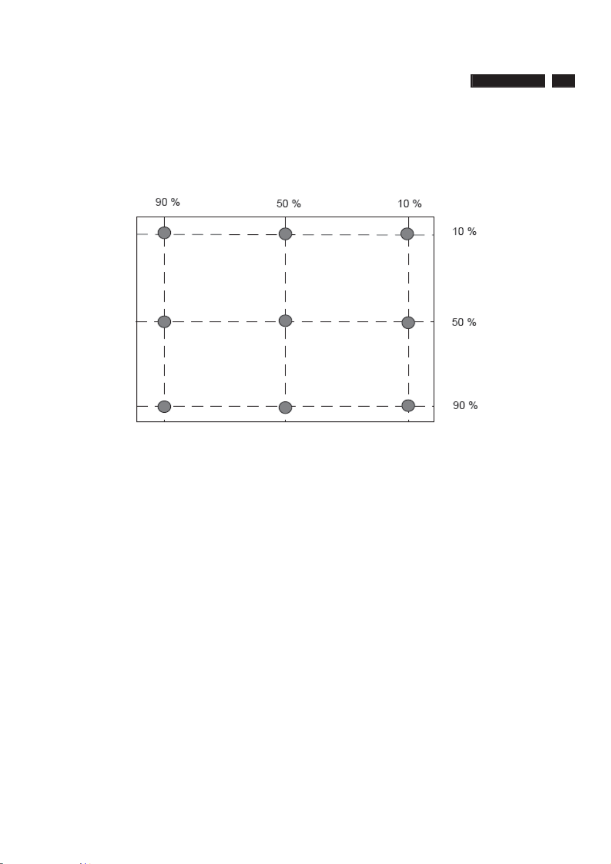
ʳ
ʳʳʳʳʳ
ʳʳʳʳʳʳʳʳʳʳʳʳʳʳʳʳʳʳʳʳʳ˃ˁ˄
ʳ
General Product Specification
ʳ
Fig 1: Measurement locations of Brightness Uniformity
222EL2 LCD 81
222E2 21.5” Wide FHD LCD Monitor
2010/02/05 PHILIPS 27 of 30
ʳ
ʳ
Page 82
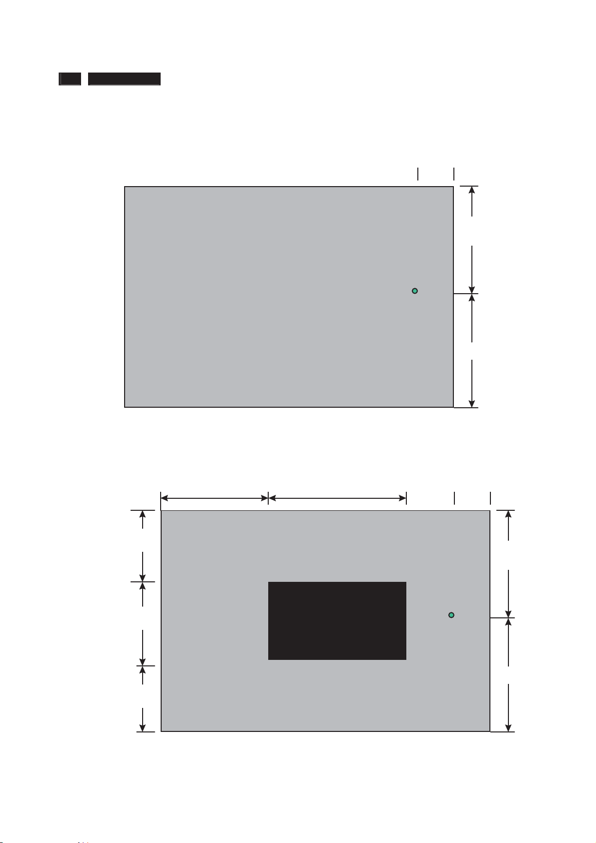
ʳ
ʳʳʳʳʳ
ʳʳʳʳʳʳʳʳʳʳʳʳʳʳʳʳʳʳʳʳʳ˃ˁ˄
ʳ
82 222EL2 LCD
General Product Specification
Fig 2: Cross talk pattern
Gray level 46 (64 Gray level)
1/6
1/2
Fig 3: Cross talk Pattern
Center at Gray level 0 (Black)
1/3 1/3
1/3
YA
1/2
1/6
1/2
1/3
YB
1/3
222E2 21.5” Wide FHD LCD Monitor
2010/02/05 PHILIPS 28 of 30
ʳ
ʳ
1/2
Page 83
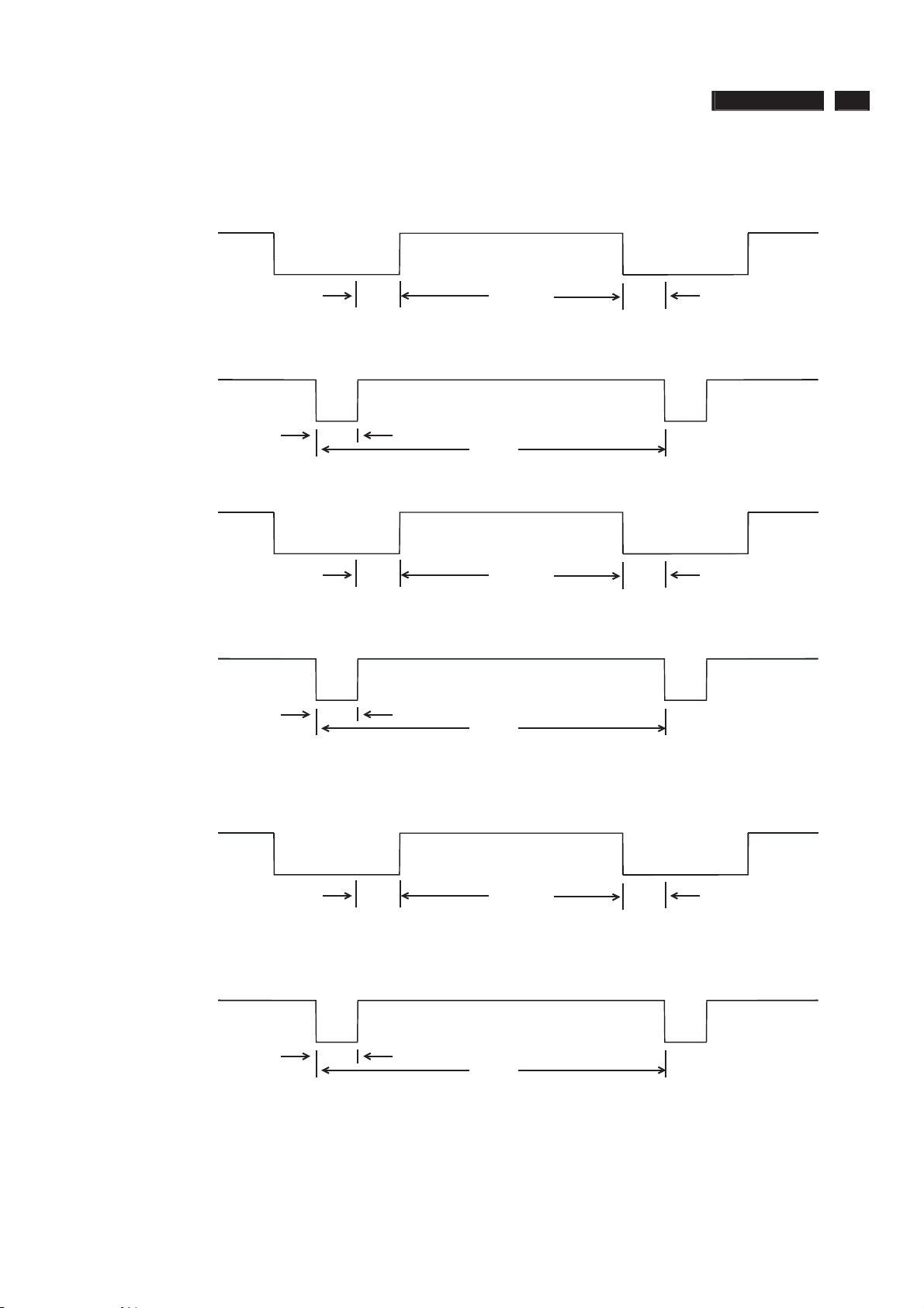
ʳ
ʳʳʳʳʳ
ʳʳʳʳʳʳʳʳʳʳʳʳʳʳʳʳʳʳʳʳʳ˃ˁ˄
ʳ
SEPARATE SYNC.
222EL2 LCD 83
General Product Specification
VIDEO
HORIZONTAL
VERTICAL
C
B
Q
P
D
A
VIDEO
R
O
E
S
COMPOSITE SYNC.
VIDEO
C
HORIZONTAL
B
D
A
E
FIG-4 TIMING CHART -1
2010/02/05 PHILIPS 29 of 30
222E2 21.5” Wide FHD LCD Monitor
ʳ
ʳ
Page 84

ʳ
ʳʳʳʳʳ
ʳʳʳʳʳʳʳʳʳʳʳʳʳʳʳʳʳʳʳʳʳ˃ˁ˄
˸
ʳ
84 222EL2 LCD
ʳ
General Product Specification
ʳ
10 REGULATORY COMPLIANCE
10.1 Worldwide Regulatory
˧ˬ˘ˀ˔˃˃˃ˇʳʳ˟˖˗ʳ
ˠˡ˧ʳ˜˸˴˼˴˿ʳ˥
10.2 EMC Requirements
Supplier DVT EMI test result must be submitted prior to DVT samples delivery, and
PVT EMI test result must be submitted again prior to PVT samples delivery. It also has
to meet Philips' immunity testing specification.
10.3 RoHS
Restriction on the use of certain hazardous substances.
Lead, Cadmium, Mercury, Hexavalent Chromium, Polybrominated Bipheny1 (PBB) and
Polybrominated Bipheny1 Ether (PBDE)(flame retardant).
10.4 WEEE
Producer (Philips) responsible for retailer take back schemes and recycling.
--System implemented.
--Collection and recycle targets.
10.5 Ongoing Regulatory
There's a possibility that other regulatory certificates will be required during the life of
the product. It is the responsibility of the supplier to provide related documentation.
222E2 21.5” Wide FHD LCD Monitor
2010/02/05 PHILIPS 30 of 30
ʳ
ʳ
Page 85
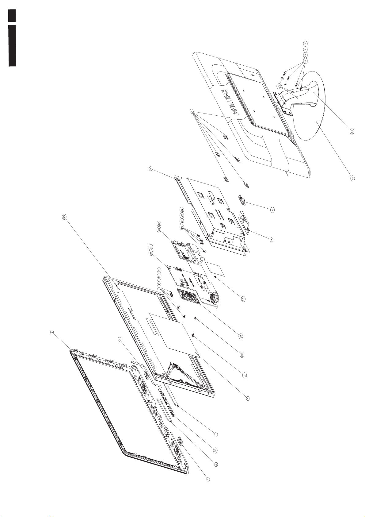
85
222EL2 LCD
iew
Exploded V
Page 86
Ϩ
!!
Ϩ
(
(
A
A
86 222EL2 LCD
Model:222EL2
Spare parts change rule:
Gray color: old parts can be ALT to new parts
Gray color with delete line: old parts can not be used to this model
Spare parts upgrade rule: last number +1 --> Latest version parts number
Example old : 6K.0QC01.011 /
new : 6K.0QC01.012
Panel+PCBA Styling
Panel+PCBA Styling
location Description PCM code AUO CMO AUO QIS AUO CMO AUO QIS AUO CMO AUO QIS AUO CMO AUO QIS AUO CMO AUO QIS AUO CMO AUO QIS AUO CMO AUO QIS AUO CMO AUO QIS AUO CMO AUO QIS AUO CMO AUO QIS AUO CMO AUO QIS AUO CMO AUO QIS AUO CMO AUO QIS
MAIN (I/F) BOARD ASS'Y28
27 POWER BOARD ASS'Y
32 CTRL BD ASS'Y
33 LEDDRIVER BD ASS'Y
LCDM21.5W M215HW01-V60B/60C Z 5F.LUAV0.071
<LT>LCDM21.5W M215HW01-V60B/60C P 5F.LUAVP.071
35
LCDM21.5W M215H3-LA1 WLED P
LCDM21.5W M215HW01 VB Z/G
SSY LCDM21.5W M215Q01 V0 Z(QISDA)6P.QUAV0.001
31 FFC CABLE 30P 16TH
Mechanical Styling
Mechanical Styling
location Description PCM code AUO CMO AUO QIS AUO CMO AUO QIS AUO CMO AUO QIS AUO CMO AUO QIS AUO CMO AUO QIS AUO CMO AUO QIS AUO CMO AUO QIS AUO CMO AUO QIS AUO CMO AUO QIS AUO CMO AUO QIS AUO CMO AUO QIS AUO CMO AUO QIS AUO CMO AUO QIS
25 BASE ASS'Y
24 COLUMN ASS'Y
2 FRONT BEZEL ASS'Y (Black) 6K.17901.001 V V V V V VVVVVVVVVVVVVVVVVVVVVVVVVVVVVVVVVVVVVVVVVVVVVVV
3 REAR COVER ASS'Y
Packing Styling
Packing Styling
location Description PCM code AUO CMO AUO QIS AUO CMO AUO QIS AUO CMO AUO QIS AUO CMO AUO QIS AUO CMO AUO QIS AUO CMO AUO QIS AUO CMO AUO QIS AUO CMO AUO QIS AUO CMO AUO QIS AUO CMO AUO QIS AUO CMO AUO QIS AUO CMO AUO QIS AUO CMO AUO QIS
CUSHION FRONT
100
110 CUSHION BACK
120 CARTON
Accessory Styling
Accessory Styling
location Description PCM code AUO CMO AUO QIS AUO CMO AUO QIS AUO CMO AUO QIS AUO CMO AUO QIS AUO CMO AUO QIS AUO CMO AUO QIS AUO CMO AUO QIS AUO CMO AUO QIS AUO CMO AUO QIS AUO CMO AUO QIS AUO CMO AUO QIS AUO CMO AUO QIS AUO CMO AUO QIS
200 QSG PHILIPS 222E2/222EL2
210 CD PHILIPS 222E2/222EL2/224E2
CORD H05VV-3G 10A250V 1500 EUR 2G.02718.051
<ALT>CORD H05VV-3G 10A250V 1500 EUR 2G.02718.05H V V V V V V V V VVVVVVVVVVVV VVVVVVVV
CORD H05VV-F 13A250V 1.5M UK 2G.03131.031 VVVV
CORD 3ASL/75DU-IN 250V1.5M AUS 2G.01343.031 VVVV
30
<ALT>CORD 3ASL/75DU-IN 250V1.5M AUS 2G.01343.061 VVVV
CORD VCTF 7A 125V 1.5M CNS-TW 2G.04811.021 VVVVVVVVVVVV
CORD RVV300/500 10A25V1.5MM 3C 2G.03745.001 VVVV
<ALT>CORD RVV300/500 10A25V1.5MM 3C 2G.03745.00H VVVV
36 CABLE SIGNAL/C H+V OD_5.5 1.8M
34 CABLE DVI-D/DVI-D 1.8M IS_8 5K.05407.511 VVVV
Critical components Model
LocationDescription PCMcode AUO CMO AUO QIS AUO CMO AUO QIS AUO CMO AUO QIS AUO CMO AUO QIS AUO CMO AUO QIS AUO CMO AUO QIS AUO CMO AUO QIS AUO CMO AUO QIS AUO CMO AUO QIS AUO CMO AUO QIS AUO CMO AUO QIS AUO CMO AUO QIS AUO CMO AUO QIS
VAR1 TVS 10D 470V TVR10471KFC3FW 2D.50009.031
U8 IC CTRL TSUMU58NWHJ-LF-1 PQFP 7A.00058.E0E
U301 IC TOUCH SENSOR CAP1006-1-AI
IC702 IC LR RM2101D0BA 3.3V TO-252 7D.02101.F3M
LED1 LED WHITE LTW-008ZDL 2.5*0.8 8C.00008.070
Model
9J.17972.*** AB1 CB1 DB1 QB1 AB5 CB5 DB5 QB5 AB7 CB7 DB7 QB7 AB6 CB6 DB6 QB6 ABH CBH DBH QBH ABM CBM DBM QBM ABK CBK DBK QBK AB3 CB3 DB3 QB3 ABG CBG DBG QBG ABJ CBJ DBJ QBJ AB4 CB4 DB4 QB4 A2A C2A D2A Q2A A28 C28 D28 Q28
5E.17901.001
5E.17901.011
5E.17901.003
5E.17901.002
5E.17901.012
5E.17901.004
5E.17902.001
5E.17803.001
5E.17933.004
5E.17933.001
5E.1A833.001
5E.1A833.002
CMO)5F.LMAPP.011
AUO)5F.LUAV0.091
5K.17803.N01
Model
6K.17810.001
6K.17809.001
6K.17902.001
6K.17902.002 V V V V V V V V V V V V V V V V V V V V V V V V V V V V V V V V V
6K.17904.001
6K.17904.002
6K.17908.001
6K.17910.001
Model
4G.17803.001
4G.17805.001
4G.17801.001
4G.17807.001
4G.17804.001
4G.17806.001
4G.17802.001
4G.17808.001
4D.17801.021
4D.17801.022
4D.17802.021
4D.17802.022
Model
4J.17801.001
4J.17801.002
5B.17801.001
5B.17801.002
5B.17801.003
5K.L2H06.501
7D.01006.0B5
B/00
2S
22EL
2
V V
VVVVVVVVVVV
VVVVVVVVVVVVVVVVVVVVVVVVVVVVVVVVVVVVVVVVVVVVVVVVVVVV
VVVVVVVVVVVVVVVVVVVVVVVVVVVVVVVVVVVVVVVVVVVVVVVVVVVV
VVVVVVVVVVVVV
VVVVVVVVVVVVV
VVVVVVVVVVVVV
VVVVVVVVVVVVV
VVVVVVVVVVVVV
VVVVVVVVVVVVVVVVVVVVVVVVVVVVVVVVVVVVVVVVVVVVVVVVVVVV
B/00
2S
22EL
2
VVVVVVVVVVVVVVVVVVVVVVVVVVVVVVVVVVVVVVVVVVVVVVVVVVVV
VVVVVVVVVVVVVVVVVVVVVVVVVVVVVVVVVVVVVVVVVVVVVVVVVVVV
V V V V V V
V V V V V
VVVVVVVVVVV
B/00
2S
22EL
2
VV VV V V VV VV VV VV VV VV
VVVVVVVVVVVVVVVVVVVVVVVVVVVVVVVVVVVVVVVV VVVVVVVV
VV VV V V VV VV VV VV VV VV
VVVVVVVVVVVVVVVVVVVVVVVVVVVVVVVVVVVVVVVV VVVVVVVV
VV VV V V VV VV VV VV VV VV
VVVVVVVVVVVVVVVVVVVVVVVVVVVVVVVVVVVVVVVV VVVVVVVV
B/00
2S
22EL
2
VV VV V V VV VV VV VV VV VV VV
VVVVVVVVVVVVVVVVVVVVVVVVVVVVVVVVVVVVVVVVVVVVVVVVVVVV
VV VV V V VV VV VV VV VV VV VV
VV VV V V VV VV VV VV VV VV VV
VVVVVVVVVVVVVVVVVVVVVVVVVVVVVVVVVVVVVVVVVVVVVVVVVVVV
VVVVVVVV VVVVVVVVVVVV VVVVVVVV
VVVVVVVVVVVVVVVVVVVVVVVVVVVVVVVVVVVVVVVV VVVVVVVV
B/00
2S
22EL
2
VVVVVVVVVVVVVVVVVVVVVVVVVVVVVVVVVVVVVVVVVVVVVVVVVVVV
VVVVVVVVVVVVVVVVVVVVVVVVVVVVVVVVVVVVVVVVVVVVVVVVVVVV
VVVVVVVVVVVVVVVVVVVVVVVVVVVVVVVVVVVVVVVVVVVVVVVVVVVV
VVVVVVVVVVVVVVVVVVVVVVVVVVVVVVVVVVVVVVVVVVVVVVVVVVVV
VVVVVVVVVVVVVVVVVVVVVVVVVVVVVVVVVVVVVVVVVVVVVVVVVVVV
B/00
2S
22EL
2
VVV V V VVVVV V V V V V V
VV VV VV VV VV VV VV VV VV VV VV
VVVVVVVVVVVVV
VVVVVVVVVVVVV
VVVVVVVVVVVVV
VVVVVVVVVVVVV
B/00
2S
22EL
2
B/00
2S
22EL
2
B/00
2S
22EL
2
B/00
2S
22EL
2
Spare / Recommended Parts List
P)
(A
B/69
2S
22EL
2
P)
(A
B/69
2S
22EL
2
P)
(A
B/69
2S
22EL
2
P)
(A
B/69
2S
22EL
2
P)
(A
69
B/
2S
22EL
2
75
B/
2S
22EL
2
B/75
2S
22EL
2
B/75
2S
22EL
2
B/75
2S
22EL
2
B/75
2S
22EL
2
B/67
2S
22EL
2
67
B/
2S
22EL
2
B/67
2S
22EL
2
B/67
2S
22EL
2
B/67
2S
22EL
2
B/01
2S
L
22E
2
B/01
2S
L
22E
2
B/01
2S
22EL
2
B/01
S
2
22EL
2
B/01
2S
22EL
2
B/70
2S
EL
22
2
B/70
2S
EL
22
2
B/70
2S
EL
22
2
B/70
S
2
EL
2
2
2
70
/
B
S
2
22EL
2
B/96
2S
EL
22
2
B/96
2S
22EL
2
B/96
2S
EL
2
2
2
B/96
2S
EL
2
2
2
/96
B
S
2
L
E
2
2
2
U)
/96
B/96
2S
EL
22
2
B/96
2S
EL
22
2
B/96
2S
EL
22
2
B/96
S
2
EL
22
2
96
/
B
S
2
L
E
2
2
2
B
S
2
22EL
2
B/96
2S
22EL
2
96
/
B
S
2
L
E
22
2
/96
B
2S
L
E
22
2
96
B/
S
2
L
E
2
2
2
B/93
2S
L
E
2
2
2
93
/
B
2S
2EL
2
2
B/93
2S
L
E
22
2
VV
VVVV
VV
VVVV
VV
VVVV
B/93
S
2
22EL
2
B/93
2S
2EL
2
2
(E
B/10
2S
22EL
A
2
1
VV
VV
10
B/
2S
EL
22
A
2
1
V VVV VV
VV
B/10
2S
A
22EL
1
2
B/10
S
2
22EL
A
2
1
/10
B
S
2
L
E
A
22
1
2
B/62
2S
A
22EL
1
2
VV
VV VV
U)
E
(
B/62
S
2
2EL
A
2
1
2
U)
(E
B/62
S
2
L
E
2
A
2
1
2
U)
E
(
(E
62
B/
S
2
L
E
2
2
A
2
1
U)
B/62
S
2
L
E
2
2
A
2
1
Page 87
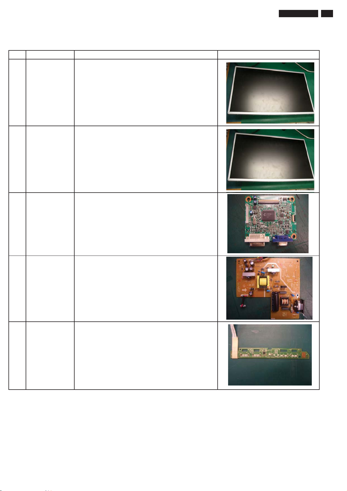
Panel & PCBA photos
ITEM PCM Description Photo
1 5F.LUAV0.071 LCDM21.5W M215HW01-V60B/60C Z (AUO)
2 5F.LMAPP.011 LCDM21.5W M215H3-LA1 WLED P (CMO)
222EL2 LCD 87
3 5E.17901.001 MAIN (I/F) BOARD ASS'Y
4 5E.17902.001 POWER BOARD ASS'Y
5 5E.17803.001 CTRL BD ASS'Y
Page 88
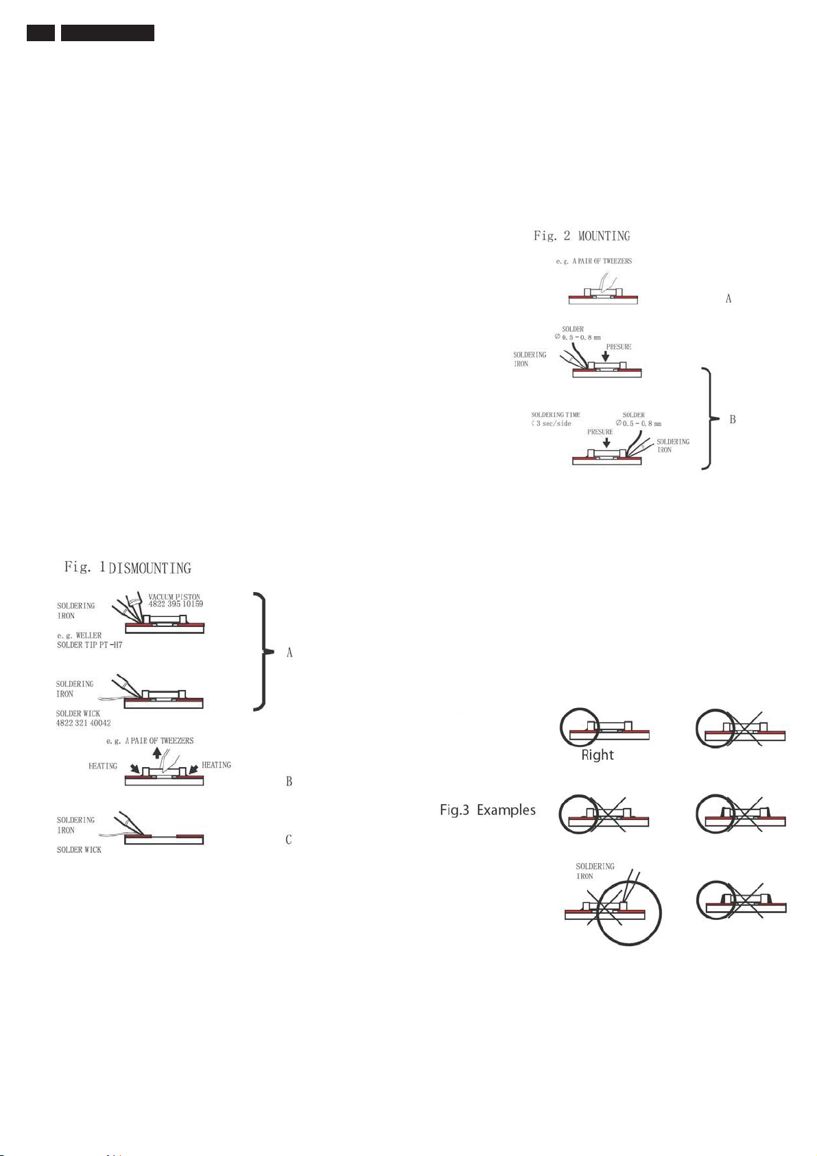
88 222EL2 LCD
5HSDLU7LSV
0. Warning
All ICs and many other semi -conductors are susceptible to
electrostatic discharges (ESD). Careless handling during repair can
reduce life drastically . When repairing, make sure that you are
connected with the same potential as the mass of the unit via a wrist
wrap with resistance. Keep components and tools also at the same
potential!
1. Servicing of SMDs (Surface Mounted Devices)
1.1 General cautions on handling and storage
- Oxidation on the terminals of SMDs results in poor soldering.
Do not handle SMDs with bare hands.
- Avoid using storage places that are sensitive to oxidation such as
places with sulphur or chlorine gas, direct sunlight, high temperatures
or a high degree of humidity. The capacitance or resistance value of
the SMDs may be affected by this.
- Rough handling of circuit boards containing SMDs may cause
damage to the components as well as the circuit boards. Circuit boards
containing SMDs should never be bent or flexed. Different circuit board
materials expand and contract at different rates when heated or cooled
and the components and/or solder connections may be damaged due
to the stress. Never rub or scrape chip components as this may cause
the value of the component to change.
Similarly, do not slide the circuit board across any surface.
1.4 Attachment of SMDs
- Locate the SMD on the solder lands by means of tweezers and solder
the component on one side. Ensure that the component is positioned
correctly on the solder lands (see Fig.2A).
- Next complete the soldering of the terminals of the component (see
Fiq. 2B).
1.2 Removal of SMDs
- Heat the solde r (for 2-3 seconds) at each terminal of the chip. By
means of litz wire and a slight horizontal force, small components can
be removed with the soldering iron.
They can also be removed with a solder sucker (see Fig. 1A)
While holding the SMD with a pair of tweezers, take it off gently using
the soldering iron's heat applied to each terminal (see Fig. 1 B).
- Remove the excess solder on the solder lands by means of litz wire or
a solder sucker (see Fig. 1C).
2. Caution when attaching SMDs
- When soldering the SMD terminals, do not touch them directly with
the soldering iron. The soldering should be done as quickly as possible,
care must be taken to avoid damage to the terminals of the SMDs
themselves.
- Keep the SMD's body in contact with the printed board when
soldering.
- The soldering iron to be used (approx. 30W)should preferably be
equipped with a thermal control (soldering temperature: 225 to 250 C).
- Soldering should not be done outside the solder land.
- Soldering flux (of rosin) may be used, but should not be acidic.
- After soldering, let the SMD cool down gradually at room temperature.
- The quantity of solder must be proportional to the size of the solder
land. If the quantity is too great, the SMD might crack or the solder
lands might be torn loose from the printed board (see Fig. 3).
While holding the SMD with a pair of tweezers, take it off gently using
the soldering iron's heat applied to each terminal (see Fig. 1 B).
- Remove the excess solder on the solder lands by means of litz wire or
a solder sucker (see Fig. 1C).
1.3 Caution on removal
- When handling the soldering.iron. use suitable pressur e and be
careful.
- When removing the chip, do not use undue force with the pair of
tweezers.
- The soldering iron to be used (approx. 30 W) should preferably be
equipped with a thermal control (soldering temperature: 225 to 250 C).
7KHFKLSRQFHUHPRYHGPXVWQHYHUEHUHXVHG
Page 89

222EL2 LCD 89
5HSDLU7LSV
3. Lead-free product identification
You can identify lead-free product by Philips-lead-free logo on PCB.
4. Lead-free product repair instruction
4.1 Use only lead-free Solder Alloy 0622 149 00106(1.2mm SAC305) or 0622 14900108(1.0mm SAC305).
Remark: For lead free soldering material, please visit www.alphametals.com website for details. This is recommended by Philips.
4.2 Use only adequate solder tools applicable for lead-free soldering-tin. The solder tool must be able to reach at least a solder-temperature of 400, to
stabilize the adjusted temperature at the solder-tip and to exchange solder-tips for different applications.
Small Passives/Actives to be removed with thermal tweezers
Automated system for IC and BGA repair (Microscope, Camera, Beam split optics, Computer, Programmer, Heat controllers, Vacuum system, Laser
pointer) Solder Hand-Tool (Adjustable in temperature height, Temperature shall be held constant, Flexible tips)
4.3 Adjust your solder tool so that a temperature around 360 -380 is reached and stabilized at the solder joint.
Heating-time of the solder-joint should not exceed ~ 4 sec. Avoid temperatures above 400 otherwise wear-out of tips will rise drastically and flux-fluid will
be destroyed. Corrosion of Tool-Spikes can be avoided when using SAC305 and a temperature of less than 400.
4.4 Mix of lead-free solder-tin/parts with leaded soldering-tin/parts is possible but not recommended. If not to avoid clean carefully the solder-joint from old
tin and re-solder with new tin.
4.5 Use only original spare-parts listed in the Service-Manuals. Standard-material (consumables) can also be purchased at external companies.
4.6 Special information for lead-free BGA-ICs: this ICs will be delivered in so-called dry-packaging to protect the IC against moisture and with lead-free
logo on it. This packaging may only be opened shortly before it is used (soldered). Otherwise the body of the IC gets wet inside and during the heating
time the structure of the IC will be destroyed due to high (steam-) pressure. If the packaging was opened before usage the IC has to be heated up for
some hours (around 90 ) for drying (Take attention for ESD-protection!)
5. Rework on BGA (Ball Grid Array) ICs
General
Although (LF)BGA assembly yields are very high, there may still be a requirement for component rework. By rework, we mean the process of removing
the component from the PWB and replacing it with a new component. If an (LF) BGA is removed from a P WB, the solder balls of the component are
deformed drastically so the removed (LF)BGA has to be discarded.
Device Removal
As is the case with any component that, it is essential when removing an (LF) BGA, the board, tracks, solder lands, or surrounding components are not
damaged. To remove an (LF)BGA, the board must be uniformly heated to a temperature close to the reflow soldering temperature. A uniform temperature
reduces the chance of warping the PWB.
To do this, we recommend that the board is heated until it is certain that all the joints are molten. Then carefully pull the component off the board with a
vacuum nozzle. For the appropriate temperature profiles, see the IC data sheet.
Area Preparation
When the component has been removed, the vacant IC area must be cleaned before replacing the (LF) BGA. Removing an IC often leaves varying
amounts of solder on the mounting lands. This excessive solder can be removed with either a solder sucker or solder wick. The remaining flux can be
removed with a brush and cleaning agent. After the board is properly cleaned and inspected, apply flux on the solder lands and on the connection balls of
the (LF)BGA
Note: Do not apply solder paste, as this has shown to result in problems during re-soldering.
Device Replacement
The last step in the repair process is to solder the new component on the board. Ideally, the (LF) BGA should be aligned under a microscope or
magnifying glass. If this is not possible, try to align the (LF)BGA with any board markers. To reflow the solder , apply a temperature profile according to
the IC data sheet. So as not to damage neighbouring components, it may be necessary to reduce some temperatures and times.
More Information
For more information on how to handle BGA devices, visit this URL: http://www.atyourservice.ce.philips.com (needs subscription). After login, select
Magazine, then go to Workshop Information. Here you will find Information on how to deal with BGA-ICs.
Page 90
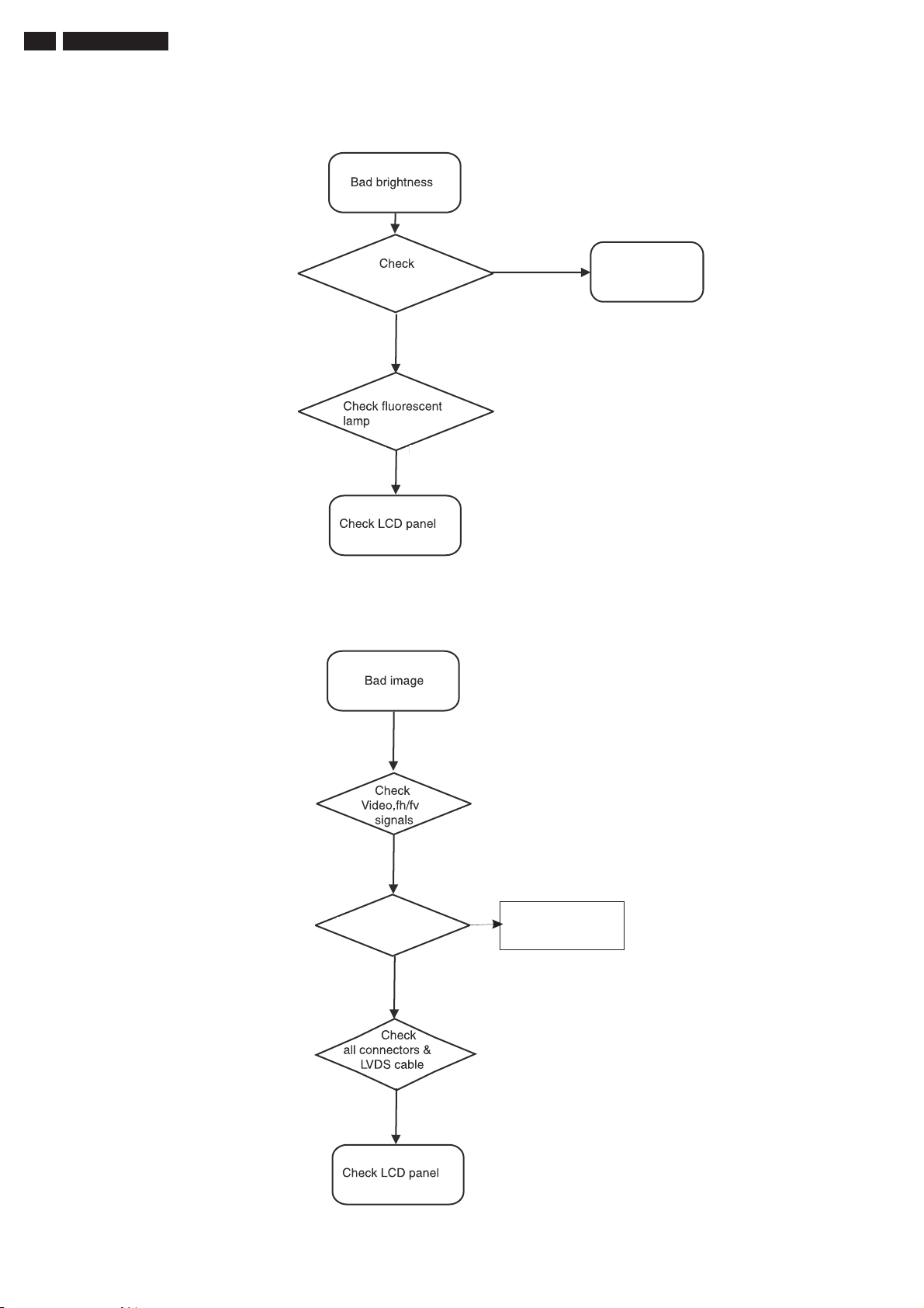
90 222EL2 LCD
Repair Flow Chart
Power Board
OK
OK
NG
Bad Power Board
OK
Check Scaler Board Bad Scaler Board
OK
OK
Page 91
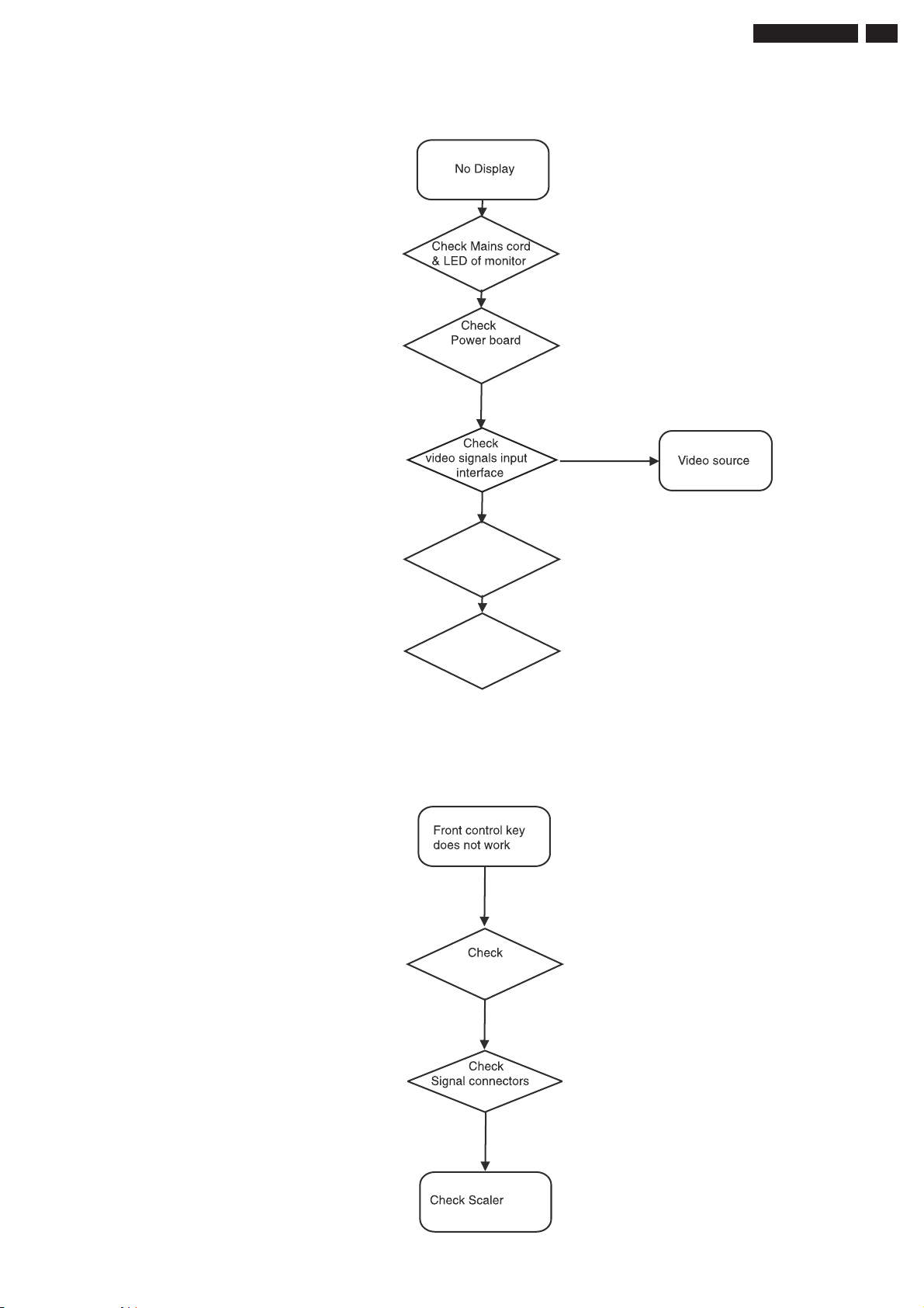
Repair Flow Chart
222EL2 LCD 91
18V/12V/5V
Check
Power Board
Check LCD Panel
DC
OK
OK
OK
NO
Control Board
OK
OK
Board
Page 92
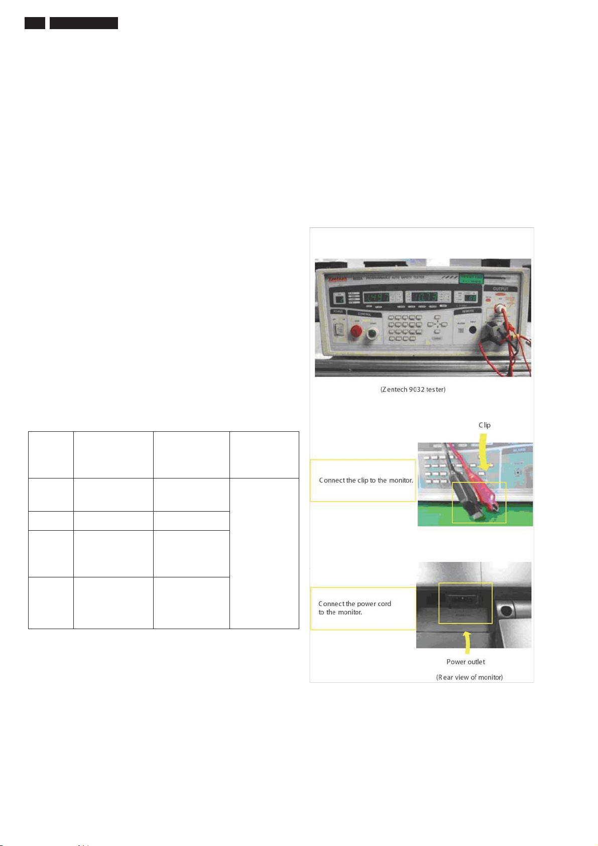
92 222EL2 LCD
Safety Test Requirements
All units that are returned for service or repair must
pass the original manufactures safety tests. Safety
testing requires both Hipot and Ground Continuity
testing.
HI-POT TEST INSTRUCTION
1.Application requirements
1.1 All mains operated products must pass the Hi-Pot
test as described in this instruction.
1.2 This test must be performed again after the
covers have been refitted following the repair ,
inspection or modification of the product.
2. Test method
2.1 Connecting conditions
2.1.1 The test specified must be applied between the
parallel blade plug of the main scord and all
accessible metal parts of the product.
2.1.2 Before carrying out the test, reliable conductive
connections must be ensured and thereafter be
maintained throughout the test period.
2.1.3 The mains switch(es) must be in the "ON"
position.
2.2 Test Requirements
All products should be HiPot and Ground Continuity
tested as follows:
3. Equipments and Connection
3.1. Equipments
For example :
- Zentech 9032 PROGRAMMABLE AUT O SAFETY
TESTER
3.2. Connection
* Turn on the power switch of monitor before Hipot
and Ground Continuity testing.
Hi-Pot Test for
Condition
Test
voltage
Test time 3 seconds 1 seconds
Trip
current
(Tester)
Ramp
time
(Tester)
products where
the mains input
is 220V AC
2820VDC
(2000VAC)
Set at 100uA for
Max limit;
Set at 0.1uA for
Min limit.
Set at 2 seconds 刈
Hi-Pot Test for
products where
the mains input
is 110V AC
1700VDC
(1200VAC)
5mA
Ground
Continuity
Test
requirement
Test current:
25A, AC
Test time: 3
seconds
Resistance
required:
<=0.09+Rohm,
Risthe
resistance of
the mains
cord.
91 220CW9
LCD
2.2.1 The minimum test duration for Quality Control
Inspector must be 1 minute.
2.2.2 The test voltage must be maintained within the
specified voltage + 5%.
2.2.3 There must be no breakdown during the test.
2.2.4 The grounding blade or pin of mains plug must
be conducted with accessible metal parts.
4. Recording
Hipot and Ground Continuity testing records have to
be kept for a period of 10 years.
 Loading...