

Philips 221P3LPEB/00, 221P3LPEB/96, 221P3LPES/00, 221P3LPES/93, 221P3LPEB/69 Service Manual
...
21.5ƎLCD Color Monitor Chassis: Meridian 3
Service
Service
Service
Description
Page
Table of Contents.........................................………….1
Revision List………….................................................2
Important Safety Notice…………................................3
1. Monitor Specifications….........................................5
2. LCD Monitor Description….....................................7
3. Operation Instructions….........................................8
3.1 General Instructions………………………….…...8
3.2 Control Buttons…………..……………………….…8
3.3 OSD Menu………………….................................9
4. Input/output Specification............................…….10
4.1 Input Signal Connector...............................……10
4.2 Resolution & Preset Modes.................................11
4.3 Pixel Defect Policy…………………………………12
4.4 Failure Mode of Panel………………………….....14
5. Block Diagram………………………….................15
5.1 Scaler Board....................................………….....15
5.2 Power/USB Board................................…...........16
6. Schematic Diagram.............................................. 17
6.1 Scaler Board…………………….…………………17
6.2 Power Board..............................................…...22
6.3 USB Board…….…………………………………25
Description
Page
6.4 IR Board…….………………………………………27
6.5 Light Board…….…………………………………29
6.6 Key Board…….……………………………………30
7. PCB Layout………………………………………...31
7.1 Scaler Board……………………………………..31
7.2 Power Board..............................................…...33
7.3 USB Board…….……………………………………36
7.4 IR Board…….…………………………….………38
7.5 Light Board…….…………………………………39
7.6 Key Board…….…………………………….………39
8. Wiring Diagram………………………………….…..40
9. Scaler Board Overview………….………………....42
10. Mechanical Instructions………………………...43
1 1. Repair Flow Chart…….……………………………46
12. ISP Instructions...…............................................50
13. DDC Instructions….............................................55
14. White Balance, Luminance Adjustment…...........65
15. Monitor Exploded View…....................................67
16. Recommended & Spare Part s List...…................68
17. General Product Specification……… …...……….70
SAFETY NOTICE
ANY PERSON ATTEMPTING TO SERVICE THIS CHASSIS MUST FAMILIARIZE HIMSELF WITH THE
CHASSIS AND BE AWARE OF THE NECESSARY SAFETY PRECAUTIONS TO BE USED WHE N
SERVICING ELECTRONIC EQUIPMENT CONTAINING HIGH VOLTAGES.
CAUTION: USE A SEPARATE ISOLATION TRANSFOMER FOR THIS UNIT WHEN SERVICING
REFER TO BACK COVER FOR IMPORTANT SAFETY GUIDELINES
Copyright 2011 Philips Consumer Lifestyle Subject to modification ƻK Aug.08, 2011
221P3LPEB/00
221P3LPEB/69
221P3LPEB/75
221P3LPEB/96
221P3LPES/00
221P3LPES/93

!
!
Meridian 3
2
Revision List
Version Release Date Revision History
A00 Aug.08, 2011 Initial release, Draft Version

3
Meridian 3
Important Safety Notice
This electronic user guide is intended for anyone who uses the Philips monitor. Take time to read this user manual
before you use your monitor. It contains important information and notes regarding operating your monitor . The
Philips guarantee applies provided the product is handled properly for its intended use, in accordance with its
operating instructions and upon presentation of the or iginal invoice or cash receipt, indicatin g the date of pu rchase,
dealers name and model and production number of the product.
Warnings
Use of controls, adjustments or procedures other than those specified in this document ation may result in exposure
to shock, electrical hazards and/or mechanical hazards. Read and follow these instructions when connecting and
using your computer monitor.
Operation
y Keep the monitor out of direct sunlight and away from stoves or any other heat source.
y Remove any object that could fall into ventilation holes or prevent proper cooling of the monitor’s electronics.
y Do not block the ventilation holes on the cabinet.
y When positioning the monitor, make sure the power plug and outlet are easily accessible.
y If turning off the monitor by detaching the power cable or DC power cord, wait for 6 seconds before attaching
the power cable or DC power cord for normal operation.
y Please use approved power cord provided by Philips all the time. If your power cord is missing, please contact
with your local service center. (Plea se refer to Customer Care Consumer Information Center)
y • Do not subject the monitor to severe vibration or high impact conditions during operation.
y • Do not knock or drop the monitor during operation or transportation.
Maintenance
y To protect your monitor from possible damage, do not put excessive pressure on the LCD panel. When moving
your monitor, grasp the frame to lift; do not lift the monitor by placing your hand or fingers on the LCD panel.
y Unplug the monitor if you are not going to use it for an extensive period of time.
y Unplug the monitor if you need to clean it with a slightly damp cloth. The screen may be wiped with a dry cloth
when the power is off. However , never use organic sol vent, such as, alcoh ol, or ammonia-ba sed liquids to clean
your monitor.
y To avoid the risk of shock or permanent damage to the set, do not expose the monitor to dust, rain, water, or
excessive moisture environment.
y If your monitor gets wet, wipe it with dry cloth as soon as possible.
y If foreign substance or water gets in your monitor, please turn the power off immediately and disconnect the
power cord. Then, remove the foreign substance or water, and send it to the maintenance center.
y Do not store or use the monitor in locations exposed to heat, direct sunlight or extreme cold.
y In order to maintain the best performance of your monitor and use it for a longer lifetime, please use the monitor
in a location that falls within the following temperature and humidity ranges.
¾ Temperature: 0-40°C 32-95°F
¾ Humidity: 20-80% RH

!
!
Meridian 3
4
y IMPORTANT: Always activate a moving screen saver program when you leave your monitor unattended.
Always activate a periodic screen refresh application if your monitor will display unchanging static content.
Uninterrupted display of still or static images over an extended period may cause “burn in”, also known as
“after-imaging” or “ghost imaging”, on your screen. "Burn-in", "after-imaging", or "ghost imaging" is a
well-known phenomenon in LCD panel technology. In most cases, the “burned in” or “after-imaging” or “ghost
imaging” will disappear gradually over a period of time after the power has bee n switched off.
Warning
Severe” burn-in” or “after-image” or “ghost image” symptoms will not disappear and cannot be repaired. The
damage mentioned above is not covered under your warranty.
Service
y The casing cover should be opened only by qualified service personnel.
y If there is any need for any document for repair or integration, please contact with your local service center.
(Please refer to the chapter of "Consumer Information Center")
y For transportation information, please refer to "Technical Specifications".
y Do not leave your monitor in a car/trunk under direct sun light.
Note
Consult a service technician if the monitor does not operate normally, or you are not sure what procedure to take
when the operating instructions given in this manual have been followed.

5
Meridian 3
1. Monitor Specifications
Technical specifications
Picture/Display
Monitor Panel Type TFT-LCD
Backlight WLED
Panel Size 21.5" W (54.6 cm)
Aspect Ratio 16:9
Pixel Pitch 0.24825 x 0.24825 mm
Brightness 250 cd/m²
SmartContrast 20,000,000:1
Contrast Ratio (typ.) 1000:1 (typ.)
Response Time (typ.) 5 ms
Optimum Resolution 1920 x 1080 @ 60Hz
Viewing Angle 176° (H) / 170° (V) @ C/R >5
Picture Enhancement SmartImage Premium
Display Colors 16.7 M
Vertical Refresh Rate 56Hz - 76Hz
Horizontal Frequency 30 KHz - 83 KHz
sRGB YES
Connectivity
Signal Input DVI-D (Digital), VGA (Analog)
Input Signal Separate Sync, Sync on Green
Convenience
User Convenience SmartImage/ź, Volume/Ÿ, Power On/Off, Sensor/Back, Menu (OK)
OSD Languages
English, French, German, Italian, Russian, Spanish,
Simplified Chinese, Portuguese
Plug & Play Compatibility DDC/CI, sRGB, Windows 7 / Vista / XP, Mac OSX, Linux
Stand
Tilt -5 / +20
Swivel -65 / +65
Height Adjustment 130 mm
Power
On mode 20.1 W (typ.), 36.9 W (max.)
On mode (ECO mode) 13.5 W (typ.)
Energy Consumption
(EnergyStar 5.0 test method)
AC Input Voltage at
100V AC +/- 5V AC,
50Hz +/- 3Hz
AC Input Voltage at
115V AC +/- 5V AC,
60Hz +/- 3Hz
AC Input Voltage at
230V AC +/- 5V AC,
50Hz +/- 3Hz
Normal Operation (typ.) 17.8 W 17.8 W 17.8 W
Sleep (Standby) 0.1 W 0.1 W 0.1 W
Off (DC switch) 0.1 W 0.1 W 0.1 W
!
!
Meridian 3
6
Power Sensor 4 W 4 W 4 W
Heat Dissipation*
AC Input Voltage at
100V AC +/- 5V AC,
50Hz +/- 3Hz
AC Input Voltage at
115V AC +/- 5V AC,
60Hz +/- 3Hz
AC Input Voltage at
230V AC +/- 5V AC,
50Hz +/- 3Hz
Normal Operation 60.75 BTU/hr 60.75 BTU/hr
60.75 BTU/hr
Sleep 0.34 BTU/hr 0.34 BTU/hr 0.34 BTU/hr
Off 0.34 BTU/hr 0.34 BTU/hr 0.34 BTU/hr
Power LED Indicator On mode: White, Standby/Sleep mode: White (blinking)
Power Supply Build-in, 100-240VAC, 50/60 Hz
Dimension
Product with Stand (W x H x D) 507 x 487 x 220 mm
Product without Stand (W x H x D) 507 x 323 x 59 mm
Weight
Product with stand 5.64 Kg
Product without stand 3.51 kg
Product with Packaging 7.43 kg
Operating Condition
Temperature Range (operation) 0°C to 40°C
Temperature Range (storage) -20°C to 60°C
Relative Humidity 20% to 80%
Altitude
operation: +120,000 ft (3,658 m)
Non-operation: + 40,000ft (12,192 m)
MTBF 30,000hrs
Environmental
ROHS Yes
EPEAT Gold (www.epeat.net)
Packaging 100% recyclable
Compliance and standards
Regulatory Approvals
BSMI, CE Mark, FCC Class B, GOAST, SEMKO, TCO5.1, TUV
Ergo, TUV/GS, UL/cUL
Cabinet
Color Black /Silver
Finish Texture
Note:
1. EPEAT Gold or Silver is valid only where Philips registers the product. Please visit www.epeat.net
for
registration status in your country.
2. This data is subject to change without notice. Go to www.philips.com/support
to download the latest
version of leaflet.
7
Meridian 3
2. LCD Monitor Description
The LCD monitor will contain a scaler board, an adapter board, a converter board, an USB board, a light board, a
key board and two IR boards. The scaler board houses the flat panel control logic, brightness control logic and
DDC.
The adapter board will provide AC to DC inverter voltage to drive the backlight of panel and the scaler board chips
each voltage.
Monitor Block Diagram
Adapter Board
(include audio)
LED Panel
Scaler Board
DVI-D
D-SUB
LED Drive
Key Board
Video signal, DDC
HOST Computer
AC IN
90 ~ 264 V
Light Board
Converter Board
IR Boards
USB Board
PC USB
!
!
Meridian 3
8
3. Operating Instructions
3.1 General Instructions
Press the power button to turn the monitor on or off.
The other control knobs are located at front panel of
the monitor. By changing these setting, the picture
can be adjusted to your personal preference.
γThe power cord should be connected.
γ Press the power button to turn on the monitor.
The power indicator will light up.
3.2 Control Buttons
Operating the Monitor
Front view product description
1.
: To access the OSD menu.
2.
: Return to previous OSD level.
3. SENSOR: power sensor.
4.
: To switch monitor’s power on and off.
5.
: To adjust the OSD menu.
6.
: To adjust brightness of this monitor.
7.
: SmartImage: there are 6 modes to be
selected: Office, Photo, Movie, Game, Economy,
Off.
Connecting to your PC
1. Kensington anti-thief lock
2. Power switch
3. AC power input
4. Audio input & Earphone
5. Display port input (unavailable for 221P3LP)
6. DVI-D input
7. VGA input
8. USB upstream
9. USB downstream
Connect to PC
1. Turn off your computer and unplug its power cord.
2. Connect the VGA or DVI signal cable for video
connection.
3. Connect the audio cable for audio connection.
4. Plug the power cord into a nearby AC power
outlet.
5. Connect the USB upstream port on the monitor
and the USB port on your computer with a USB
cable. The USB downstream port is now ready for
any USB device to plug in.
6. Turn on your computer and monitor. If the monitor
displays images, the installation is done.
9
Meridian 3
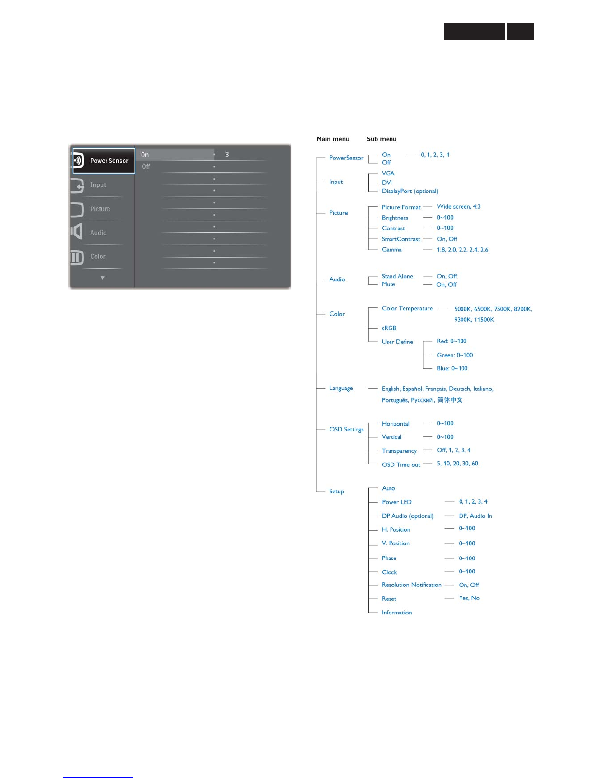
3.3 OSD Menu
On-screen Display (OSD) is feature in all Philips
monitors. It allows an end user to adjust screen
performance or select functions of the monitors directly
through an on-screen instruction window. A user
friendly on screen display inter face is shown as below:
Basic and simple instruction on the control keys
In the OSD shown above users can press źŸ buttons
at the front bezel of the monitor to move the cursor, OK
to confirm the choice or change.
To Lock/Unlock OSD function (User Mode)
The OSD function can be locked by pressing “MENU”
button for more than 10 seconds.
Locked OSD function can be released by pressing
“MENU” button for more than 10 seconds again.
The OSD tree
Below is an overall view of the structure of the
On-Screen Display. You can use this as a reference
when you want to work your way around the different
adjustments later on.

!
!
Meridian 3
10
4. Input/ Output Specification
4.1 Input Signal Connector
Analog Connector
Pin No.
Signal Name
Pin No.
Signal Name
1
Red
9
DDC +3.3V or +5V
2
Green/ SOG
10
Logic GND
3
Blue
11
Sense (GND)
4
Sense (GND)
12
Bi-directional data
5
Cable Detect (GND)
13
H/H+V sync
6
Red GND
14
V-sync
7
Green GND
15
Data clock
8
Blue GND
Digital Connector
Pin No.
Signal Name
Pin No.
Signal Name
1
T.M.D.S. data2-
13
No Connect
2
T.M.D.S. data2+
14
+5V Power
3
T.M.D.S. data2 shield
15
Ground (for +5V)
4
No Connect
16
Hot plug detect
5
No Connect
17
T.M.D.S. data0-
6
DDC clock
18
T.M.D.S. data0+
7
DDC data
19
T.M.D.S. data0 shield
8
No Connect
20
No Connect
9
T.M.D.S. data1-
21
No Connect
10
T.M.D.S. data1+
22
T.M.D.S clock shield
11
T.M.D.S. data1 shield
23
T.M.D.S. clock+
12
No Connect
24
T.M.D.S. clock-
11
Meridian 3
4.2 Resolution & Preset Modes
Maximum Resolution
1920 x 1080 at 60 Hz (analog input)
1920 x 1080 at 60 Hz (digital input)
Recommended Resolution
1920 x 1080 at 60 Hz (digital input)
H. freq (kHz) Resolution V. freq (Hz)
31.47 720 x 400 70.09
31.47 640 x 480 59.94
35.00 640 x 480 66.67
37.86 640 x 480 72.81
37.50 640 x 480 75.00
37.88 800 x 600 60.32
46.88 800 x 600 75.00
48.36 1024 x 768 60.00
60.02 1024 x 768 75.03
63.89 1280 x 1024 60.02
79.98 1280 x 1024 75.03
55.94 1440 x 900 59.89
70.64 1440 x 900 74.98
65.29 1680 x 1050 59.95
67.50 1920 x 1080 60.00
Note:
Please notice that your display works best at native resolution of 1920 x 1080@60Hz. For best display quality,
please follow this resolution recommendation.
Power Management Definition
Power Management Definition
VESA Mode Video H-Sync V-Sync Power Used LED Color
Active ON Yes Yes < 20.1 W (typ.) White
Sleep (Standby) OFF No NO < 0.1 W (typ.) White (Blinking)
Switch off OFF - - 0 W (typ. AC switch) OFF
Note:
This data is subject to change without notice.
!
!
Meridian 3
12
4.3 Pixel Defect Policy
Philips strives to deliver the highest quality products.
We use some of the industry’s most advanced
manufacturing process and practice stringent quality
control. However, pixel or sub pixel defects on the TFT
LCD panels used in flat panel monitors are sometimes
unavoidable. No manufacturer can guarantee that
panels will be free from pixel defects, but Philips
guarantees that any monitor with an unacceptable
number of defects will be repaired or replaced under
warranty. This notice explains the different types of
pixel defects and defines acceptable defect levels for
each type. In order to qualify for repair or replacement
under warranty, the number of pixel defects on a TFT
LCD panel must exceed these acceptable levels. For
example, no more than 0.0004% of the sub pixels on a
21.5Ǝ XGA monitor may be defective. Furthermore,
Philips sets even higher quality st andard for certain
types or combinations of pixel defects that are more
noticeable than others. This policy is valid worldwide.
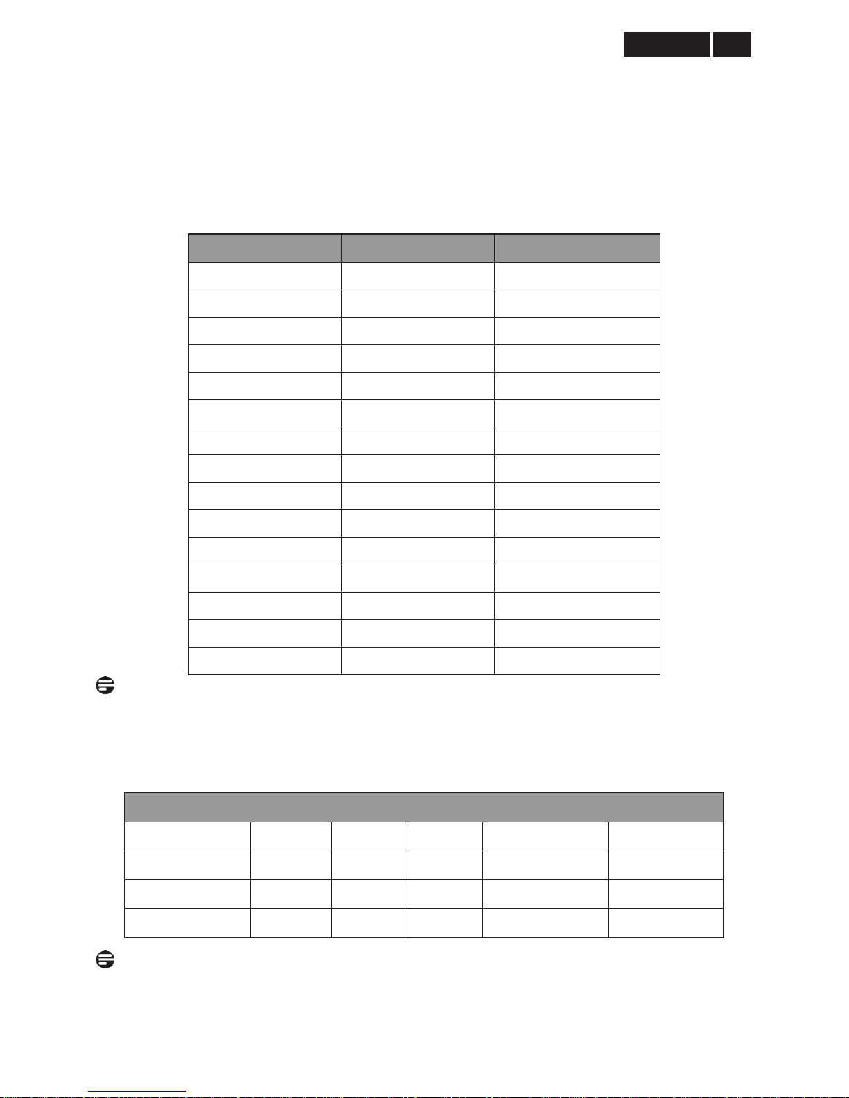
Pixels and Sub pixels
A pixel, or picture element, is composed of three sub
pixels in the primary colors of red, green and blue.
Many pixels together form an image. When all sub
pixels of pixel are lit, the three colored sub pixels
together appear as a single white pixel. When all are
dark, the three colored sub pixels together appear as a
signal black pixel. Other combinations of lit and dark
sub appear as single pixels of other colors.
Types of Pixel Defects
Pixel and sub pixel defects appear on the screen in
different ways. There are two categories of pixel
defects and several types of sub pixel defects within
each category.
Bright Dot Defects Bright dot defects appea r as pixels
or sub pixels that are always lit or ‘on’. That is, a Bright
dot is a sub-pixel that stands out on the screen when
the monitor displays a dark pattern. There are three
types of bright dot defects:
One lit red, green or blue sub pixel
Two adjacent lit sub pixels:
- Red + Blue = Purple
- Red + Green = Yellow
- Green + Blue = Cyan (Light Blue)
Three adjacent lit sub pixels (one white pixel)
Note:
A red or blue bright dot must be more than 50 percent
brighter than neighboring dots while a green bright dot
is 30 percent brighter than neighboring dots.
13
Meridian 3
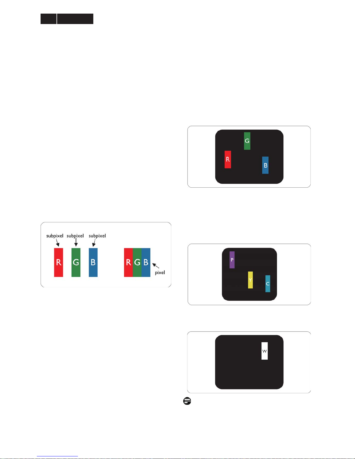
Black Dot Defects Black dot defects appea r as pixels
or sub pixels that are always dark or ‘off’. That is, a
dark dot is a sub-pixel that stands out on the screen
when the monitor displays a light pattern. There are
two types of black dot defects:
Proximity of Pixel Defects
Because pixel and sub pixels defects of the same type
that are near to one another may be more noticeable,
Philips also specifies tolerances for the proximity of
pixel defects.
Pixel Defect Tolerances
In order to qualify for repair or replacement due to pixel
defects during the warranty period, a TFT LCD pa nel in
a Philips flat panel monitor must have pixel or sub pixel
defects exceeding the tolerances listed in the following
tables.
Bright Dot Defects Acceptable level
1 lit subpixel 3
2 adjacent lit subpixels 1
3 adjacent lit subpixels (one white pixel) 0
Distance between two bright dot defects* >15mm
Total bright dot defects of all types 3
Black Dot Defects Acceptable level
1 dark subpixel 5 or fewer
2 adjacent dark subpixels 2 or fewer
3 adjacent dark subpixels 0
Distance between two black dot defects* >15mm
Total black dot defects of all types 5 or fewer
Total Dot Defects Acceptable level
Total bright or black dot defects of all types 5 or fewer
Note:
1. 1 or 2 adjacent sub pixel defects = 1 dot defect.
2. This monitor is ISO9241-307 compliant. (ISO9241-307: Ergonomic requirement, analysis and
compliance test methods for electronic visual displays)
!
!
Meridian 3
14
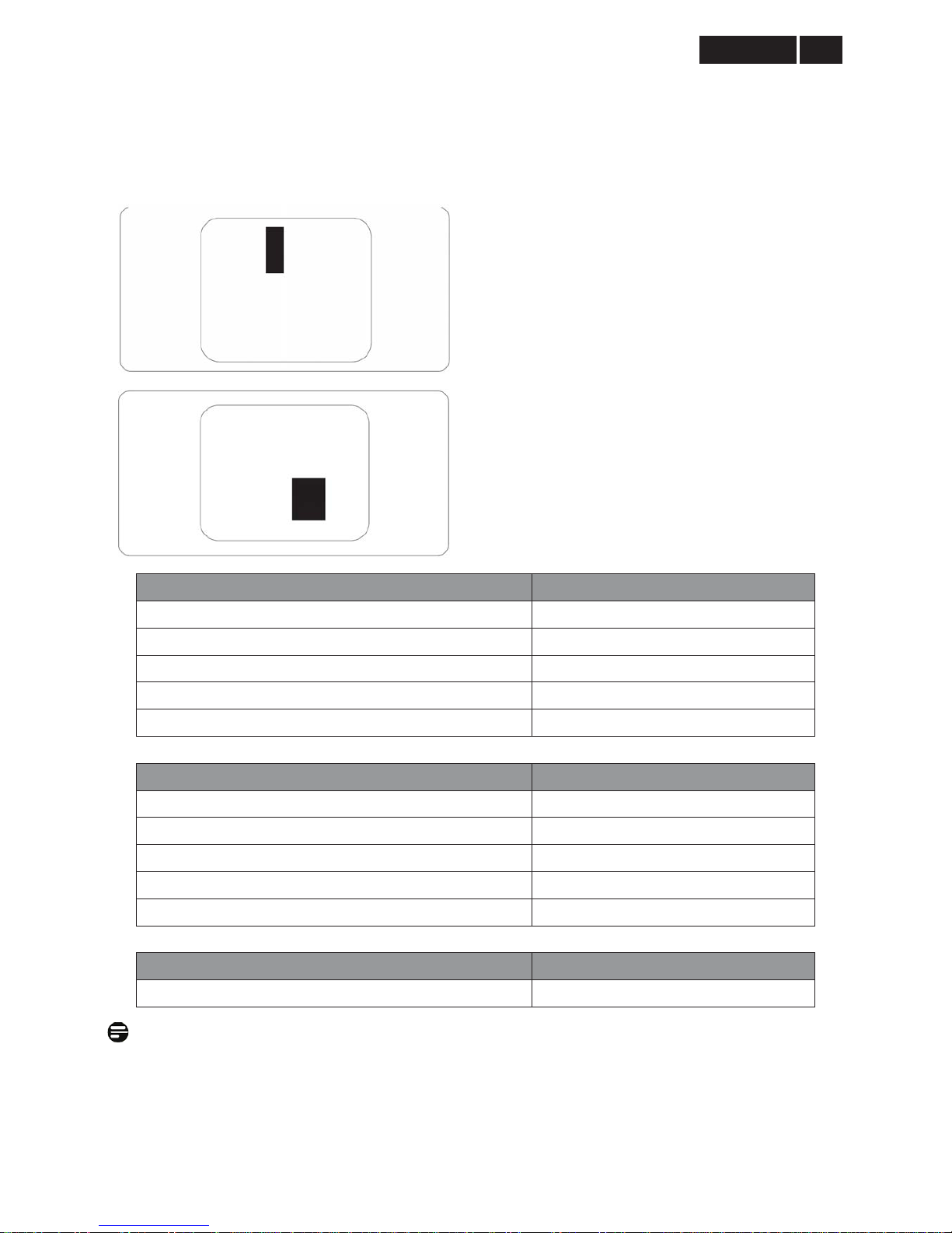
4.4 Failure Mode Of Panel
Failure description
Phenomenon
Vertical block defect
Vertical dim lines
Vertical lines defect
(Always bri
g
ht or dark)
Horizontal block de fect
Horizontal dim lines
Horizontal lines defect
(Always bri
g
ht or dark)
Has bri
g
ht or dark pixel
Polarizer has bubbles
Polarizer has bubbles
Foreign material inside
polarizer. It shows liner or
dot shape.
Concentric circle formed
Bottom back light of LCD is
brighter than normal
Back light un-uniformity
Backli
g
ht has foreign material.
Black or white color, liner or
circular type
Quick reference for failure mode of LCD panel
this pa
g
e presents problems that could be made by LCD panel.
It is not necessary to repair circuit board. Simply follow the mechanical
instruction on this manual to eliminate failure by replace LCD panel.
15
Meridian 3
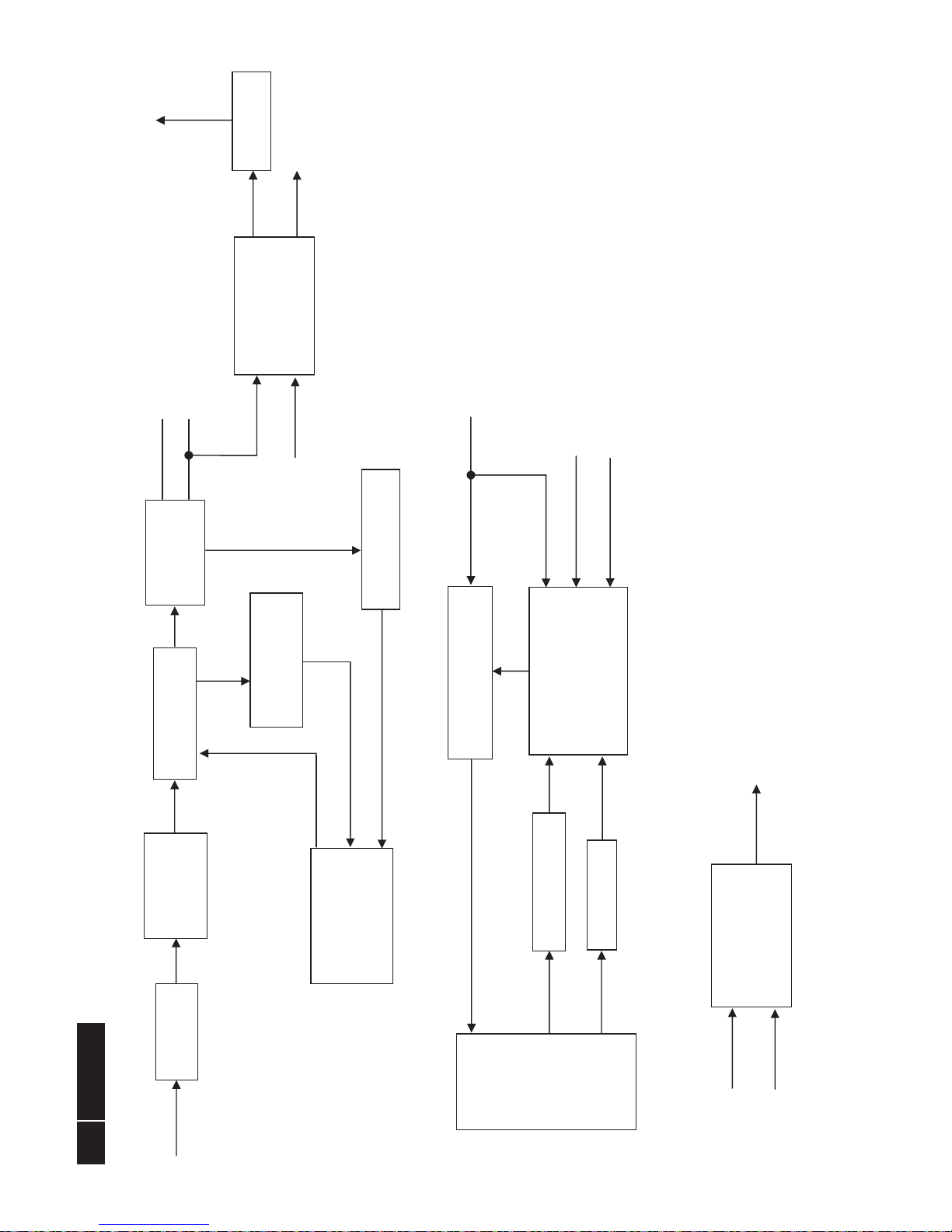
5. Block Diagram
5.1 Scaler Board
05.PAN EL I N TERF AC E
05.PAN EL I N TERF AC E
VLCD
PA[0..9]
PB[0..9]
RX1-
DVI_CA B L E _ DE T
DDCSCL1
AHS0
AVS0
RXC+
R0-
VLCD
EDID_WP
VGA_CABLE_DET
EDID_WP
PB[0..9]
Adj_BACKLIGHT
RX2+
02.INPUT
02.D-SUB INPUT
R0+
R0-
SOG_DET
G0+
G0-
B0+
B0-
+5V
AHS0
AVS0
DDCSCL1
DDCSDA1
EDID_WP
VGA_CABLE_DET
on_BACKLIGHT
+5V
G0+
DDCSDA2
VCC3.3
PS_EN
VLCD
EDID_WP
VCC1.8
RX0-
06.POWER
06.POWER
Adj_BACKLIGHT
on_BACKLIGHT
Audio_VOL
Audio_MUTE
PS_EN
Panel_ON
+5V
VCC3.3
VCC1.8
VLCD
VCC1.8
Audio_MUTE
DDCSDA1
+5V
B0-
Panel_ON
SOG_DET
DVI_HPD
RX0+
+5V
PA[0..9]
RX2-
04.SCALER
04.SCALER
Adj_BACKLIGHT
on_BACKLIGHT
Audio_VOL
Audio_MUTE
PS_EN
Panel_ON
PB[0..9]
PA[0..9]
R0+
R0-
SOG_DET
G0+
G0-
B0+
B0-
AHS0
AVS0
DDCSCL1
DDCSDA1
EDID_WP
VGA_CABLE_DET
RXC+
RXC-
RX2-
RX2+
RX1+
RX1-
RX0-
RX0+
DDCSCL2
DDCSDA2
DVI_CABLE_DET
DVI_HPD
VCC1.8
VCC3.3
+5V
RX1+
+5V
B0+
VCC3.3
Audio_VOL
03.DVI INPUT
03.DVI INPUT
RX0+
RX0-
RX1-
RX1+
RX2+
RX2-
RXC-
RXC+
DDCSCL2
DDCSDA2
DVI_CABLE_DET
EDID_WP
+5V
DVI_HPD
R0+
G0-
RXC-
DDCSCL2
!
!
Meridian 3
16
5.2 Power/USB Board
EMI filter
PWM Control
TOP266EG
(IC901)
Transformer
AC input
16V
5V
Bridge
Rectifier and
Filter
Feedback Circuit
Rectifier
Diodes
Photocoupler
(IC903)
Audio Amplifier IC
APA2071JI-TUG
(IC601)
ENA
Feedback Circuit
LED Bar
Boost Circuit
12V
OVP Circuit
Setup-up Controller
TA9690GN
(IC801)
DIM
Speaker
Audio in
USB Board
Hub Controller IC
USB2514B-AEZG
(U752)
16V
USB Upstream
USB Downstream
Earphone
17
Meridian 3
6. Schematic
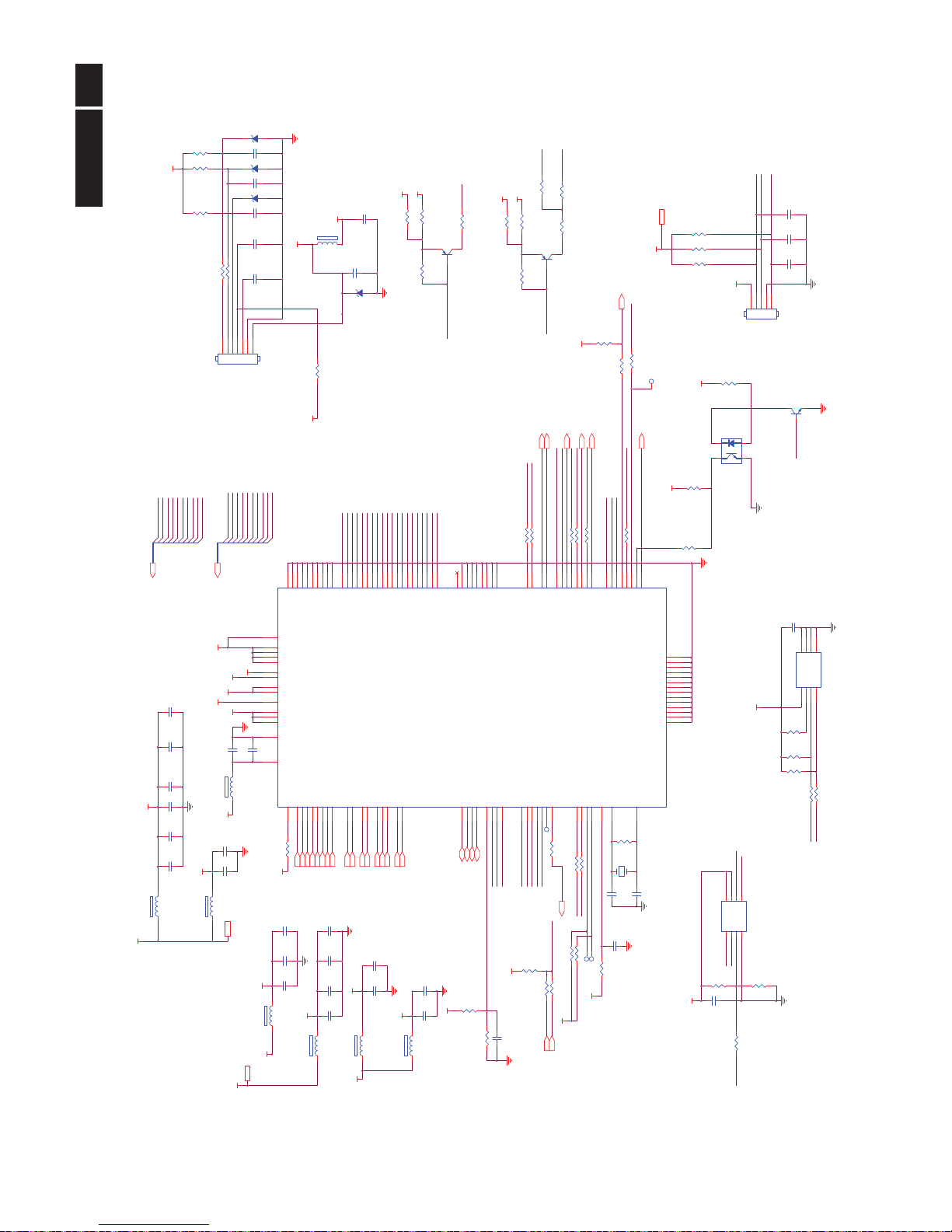
6.1 Scaler Board (715G4592M01000004I)
Remark: Parts position can be searched by using FIND function in PDF.
R124 100R 1/1 6W 5%
ESD_VGA
RIN0-
U101
AT24C02BN-SH-T
123
45
678
A0A1A2
GNDSDA
SCLWPVCC
R121
100R 1/16W 5%
EDID _WP
C181
22PF 50V
G0- 5
C108
47N 16V
R122 0R05 1/10W
R117
0R05 1/ 16W
DDCSCL15
C182
22PF 50V
BIN0
R108
100R 1/16W 5%
C103
5PF 50V
GIN0-
DDCSCL_A
ZD101
RLZ5.6B
R103
0R05 1/16W
BIN0
DDCSCL1
R104
0R05 1/1 6W
BIN0-
R115 4K7 1/16W 5%
C114
100N 16V
GIN0
R107
75R 1/16 W 1%
C109
5PF 50V
VGA_5V
B0+
+5V4,5,7
RIN0
R123 100R 1/1 6W 5%
ESD_VGA
+5V
D101
BAV70
3
1
2
DET_VGA
R106
100R 1/ 16W 5%
C112
NC/ 22pF 50V
C106
5PF 50V
R116 22K 1/16W 5%
DET_VGA
R0- 5
HSIN0
VGA_CABLE_DET
GIN0
B0- 5
HSIN0
R113
100R 1/16W 5%
G0-
RIN0-
RIN0
VSIN0
BIN0
R109
0R05 1/16W
R0+
G0+
R120
75R 1/16W 1%
R101
100R 1/ 16W 5%
R111
100R 1/16W 5%
C120
1N 50V
FB412
300 OHM
C113
100N 16V
C107
47N 16V
R0+ 5
U102
AOZ8902CIL
123 4
5
6
CH1VNCH2 CH3
VP
CH4
GIN0-
DDCSCL_A
R102 100R 1/16W 5%
CN101
DB15
162738495
11
12
13
14
15
10
17 16
C110
47N 16V
SOG_DET 5
C111
NC/ 22pF 50V
DDCSDA1
DDCSDA_A
R112
75R 1/16W 1%
C101
220N16V
B0+ 5
R142
470R 1/16W 5%
R118
0R05 1/1 6W
HSIN0
BIN0-
C104
47N 16V
DDCSDA15
EDID_WP4,5
R0-
VSIN0
U103
AOZ8902CIL
123 4
5
6
CH1VNCH2 C H3
VP
CH4
DDCSDA1
VGA_5V
R114 4K7 1/16W 5%
RIN0
VSIN0
DDCSDA_A
G0+ 5
R110
0R05 1/1 6W
R125
2K2 1/16W 5%
C102
47N 16V
VGA_CABLE_DET 5
B0-
C105 47N 16V
FB411
300 OHM
ESD_VGA
R119
100R 1/16W 5%
AHS0 5
DDCSCL1
R126
2K2 1/16W 5%
AVS0 5
GIN0
VGA_5V
R105
100R 1/16W 5%
D-SUB I/O
!
18
Meridian 3
Remark: Parts position can be searched by using FIND function in PDF.
R138 10R 1 / 16W 5%
RX1- 5
U105
AT24C02BN-SH-T
123
45
678
A0A1A2
GNDSDA
SCLWPVCC
EDID_WP 3,5
R137 10R 1 / 16W 5%
U104
AOZ8902CIL
123 4
5
6
CH1VNCH2 CH3
VP
CH4
DAT2-
ZD102
RLZ5.6B
R141 10R 1 / 16W 5%
C119
100N 16V
U106
AOZ8902CIL
123 4
5
6
CH1VNCH2 CH3
VP
CH4
ESD_DVI
CN102
JACK
1
2
3
4
5
678
9
10
11
12
13
141516
17
18
19
20
212223
24
26
25
27
28
DAT2-
DAT2+
2/4shield
DAT4-
DAT4+
DDC SCL
DDC SDA
VSYNC
DAT1-
DAT1+
1/3shield
DAT3-
DAT3+
+5V
SYNC GND
HPD
DAT0-
DAT0+
0/5shield
DAT5-
DAT5+
clk shield
clk+
clk-
GND
GND
GND
GND
DAT0+
+5V
C115
100N 16V
R140 10R 1 / 16W 5%
C118
100N 16V
ESD_DVI
RX0- 5
ESD_DVI
DET_DVI
DVI5V
R139 10R 1 / 16W 5%
Q101
NC
RX0+ 5
SDA_DVI
DCLK-
DDCSCL2 5
DAT1-
FB410
300 OHM
HPD
DVI_HPD 5
R132 4K7 1/ 16W 5%
DDCSDA2 5
DVI5V
DVI5V
RX2- 5
R135 10R 1 / 16W 5%
RX1+ 5
U107
AOZ8902CIL
123 4
5
6
CH1VNCH2 CH3
VP
CH4
RXC+ 5
C117
100N 16V
DVI_CABLE_DET 5
DAT1+
D102
BAV70
3
1
2
DAT2+
ESD_DVI
RXC- 5
RX2+ 5
R130 1K 1/16W
DCLK+
+5V3,5,7
R134 10R 1 / 16W 5%
R133 22K 1/ 16W 5%
ESD_DVI
SCL_DVI R128 100R 1 / 16W 5%
R136 10R 1 / 16W 5%
ESD_DVI
DAT0-
DDC_WP
C116
220N16V
R131 4K7 1/ 16W 5%
R127
100R 1/16 W 5%
R129 100R 1 / 16W 5%
DVI
19
Meridian 3
Remark: Parts position can be searched by using FIND function in PDF.
SPI_CK
R439 100R 1/16W 5%
DDCSDA13
EDID_WP
C407
100N 16V
U401
NT68668AUFG/C
1
2
3
4
567
8
9
10
111213
14
15
16
17
18
19202122232425
26
27
28
293031
32
333435
3637383940
41
42
43
44
45
46
47
484950
51
52
53
545556575859606162
63
64
102
101
1009998979695949392
91
90
89
888786858483828180
7978777675747372717069
68
676665
128
127
126
125
124
123
122
121
120
119
118
117
116
115
114
113
112
111
110
109
108
107
106
105
104
103
RSTB
DVDD_ZP
DGND
RX2+
RX2-
AVCC
RX1+
RX1-
AGND
RX0+
RX0-
AGND
RXC+
RXC-
AVCC
REXT
ADC_BIAS
PGND
BIN1+
BIN1-
SOG1I
GIN1+
GIN1-
RIN1+
RIN1-
ADC_VAA18
ADC_GNDA
ADC_VAA33
PD6
PB3/ADC3/ INTE1
P31/TXD
P30/RXD
PB2/ADC2/ INTE0
PB7/DDC _SDA1*
PB6/DDC _SCL1*
PA3/PWM5
PA4/PWM6*
PA5/PWM7*
PA6/PWM8*
PA7/PWM9*
HSYNCI1
VSYNC I1
PLL_GND
GND
PLL_DVDD
PB5/DDC _SDA0*
PB4/DDC _SCL0*
PD5
P35
P34
DVDD
CVDD
NC
V0V1V2V3V4V5V6
V7
VCKI
NC
DGND/CGND
PC6
NC
NCNCNCNCNCNCNCNCNC
NC
DVDD
NC
T0M
T0P
T1M
T1P
T2M
T2P
TCLK 1M
TCLK1P
T3M
T3P
DGND/CGND
T4M
T4P
T5M
T5P
T6M
T6P
TCLK 2M
TCLK2P
T7M
T7P
PA1/PWM3
PA2/PWM4
PA0/PWM2
OSCO
OSCI
PB0/ADC0
PB1/ADC1
PC5
PC4/PWM1
PC3/PWM0
PC1*
PC0*
CVDD_ZP
PWMB*
PWMA*
DVDD
CVDD
INT_HSO
INT_VSO
NC
NC
PC2
GND
PD4
SPI_CLK
SPI_SI
SPI_SO
SPI_CE
PC7
C406
1uF 10V
DVDD
LVACKP
LED_2
DVDD
PB6
piove_po wer
R460NC/10K+-5%1/16W
C402
100N 16V
RX0+4
AVCC
VCC3.3a
PB5
C417
100N 16V
ADC_VAA33
VCC3.3
PA7
LVB0M
LVA1P
LVB0P
LVACKM
R0+
SOG_DET3
LVBCKM
FB401
300OHM
VCC3.3a
RX1+
PA3
DVDD
PB1
MSCL
LED_A
C426 22PF 50V
Audio_MUTE 6
piovt
Q401
2N3906S-RTK/PS
R413
2K2 1/16W 5%
LVB3M
SPI_SI
POWER
C408
100N 16V
ADC_BIAS
ADC_VAA
C419
100N 16V
AVS03
RX1-
PA2
FB408
300OHM
C414
1uF 10V
C0402
R405
NC/3.9K 1/16W
AVCC
PB4
R0-
C428 22PF 50V
VGA_CABLE_DET3
Audio_MUTE
R425 10K 1/16W 5%
R438
NC/10K 1/16W 5%
LVA3P
R443 NC / 4. 7 K 1/ 16W
LVBCKP
C720
47pF 50V
WP
R414
NC/0R 05 1/ 16W
PB2
LED_A
R434 NC/100R 1/ 1 6W 5%
U403
NC/M24C16
123
45
678
A0A1A2
GNDSDA
SCLWPVCC
HSO
PA5
PA0
LED_1
piove_power
R421 100R 1/16W 5 %
VCC3.3a
Adj_BACKLIGHT
PS_EN
RX0-4
VCC3.3 7
SPI_CE
RX2-4
RXC-
LED_1
PS_OUTPUT
PB3
FB403
300OHM
C413
4.7UF 10 V
C0805
LVB3M
CN406
CONN
12345
VCC3.3
PB8
RX1-4
VCC3.3
MSCL
SPI_SO
LVB3P
C412
NC/0.1uF 25V
AVCC
LVA0P
FB406
300OHM
1 2
C418
100N 16V
C722
47pF 50V
+5V
RX0+
LVB1P
DDCSCL2
KEY2
PA8
PA5
LVA2P
C431
100N 16V
TP5
R412
NC/0R 05 1 / 16W
PS_ON
Panel_ON 7
Audio_VOL 6
5V_DET
PB0
C425 100N 16V
TP3
C421
4.7UF 10V
C0805
C420
1uF 10V
R416
220K 1/16W 5%
D404
RLZ5.6B
DVI_HPD 4
PA3
VGA_CABLE_DET
R417
100R 1/10W 5%
AVS0
R419
390K
MSDA
PA1
R0+3
PB5
LED_A
LED_G
LVBCKM
Panel_ON
B0+
R461NC/10K+-5%1/16W
TP1
VCC3.3
HSO
PB9
KEY1
D403
RLZ5.6B
B0-3
PA4
R452 NC
DDCSDA24
LVB3P
PB2
C721
47pF 50V
PA[0..9]6
PB7
RX1+4
R428 NC/100R 1/16W 5%
RX2-
EE_WP
R415
100K 1/16W 5%
VCC3.3a
VSO
R423 220K 1/16W 5%
R407
0R05 1/16W
R0-3
VCC3.3
PB7
EDID_WP
DVI_CABLE _ DE T
R429
30Kohm 1/16W +/- 5%
+5V
LVA2M
PA4
+5V
+5V
C403
100N 16V
PA9
PA1
CABLE_DET
DDCSCL1
PS_DISTANCE
DVDD
LVB1M
R409
0R05 1/16W
R454
0R01 1/10W
OC1
RBS311115
4 3
1 2
RXC-4
Adj_BACKLIGHT 6
ADC_BIAS
KEY2
PS_ON
Q403
LMBT3904LT1G
WP
D402
RLZ5.6B
R422 100K 1/16W 5%
C427
100N 16V
D401
NC/RLZ5.6B
R447
NC/100R 1/16W 5%
DDCSDA2
X40 1
12MHz
1 2
PS_EN 6
LVACKP
PB4
LVA0M
PA7
LVB1M
LED_G
LVB2P
R450 10K 1/16W 5%
R420 120R 1/16W 1%
C404
4.7UF 10V
C0805
PB[0..9]6
ADC_VAA
CABLE_DET
LVA3M
LVA2P
C423
4.7UF 10V
C0805
FB402
300OHM
C415
1uF 10V
C0402
EE_WP
R431
100R 1/16W 5%
C401
100N 16V
C430
NC/220N16V
CVDD
CN404
CONN
1234567
RX2+
LVA1M
R437
100R 1/16W 5%
+5V
VCC3.3a
KEY1
LVA3M
C409
100N 16V
PB3
LVBCKP
MSDA
C438
1UF
G0+3
SPI_CK
LVB2P
AHS03
RX2+4
LVB2M
G0-
R432
1M 1/16W
C405
100N 16V
LVB0P
PA8
+5V
SPI_SO
DVI_HPD
R430
NC/22K 1/16W 5%
LED_2
R410
0R05 1/16W
RXC+4
DDCSCL13
DDCSCL24
VCC3.3a
LVA2M
ADC_VAA33
C416
4.7UF 10V
C0805
on_BACKLIGHT 6
R442 NC / 4. 7 K 1/ 16W
R441 NC / 4. 7 K 1/ 16W
SPI_SI
PA[0..9]
RXC+
R401
NC/3.9K 1/16W
R436
100R 1/10W 5%
LVA3P
C411
NC/0.1uF 25V
Q402
2N3906S-RTK/PS
PS_DISTANCE
R444
10K 1/16W 5%
R418
100R 1/10W 5%
C410
NC/1N 50V
R453
NC/0R 05 1 / 10W
PB[0..9]
R424 0R05 1/16W
R406
0R05 1/16W
R433
NC/10K 1/ 16W 5%
R404
NC/3.9K 1/16W
PB1
LVA0P
AHS0
R427 10K 1/16W 5%
RX0-
LVB1P
PA6
on_BACKLIGHT
C439
1UF 10V
+5V
LVACKM
PB6
PA2
Audio_VOL
TP4
C422
100N 16V
PS_OUTPUT
POWER
B0+3
G0-3
+5V 7
PB8
SOG_DET
R426 NC/100R 1/16W 5%
VCC1.8
VSO
PA6
B0-
R408
470R 1/16W 1%
C424
1uF 10V
C0402
FB405
300OHM
R411
2K2 1/16W 5%
PA0
R445
NC/100R 1/16W 5%
SPI_CE
LVA1M
R46210K+-5%1/16W
FB407
300OHM
VCC3.3a
VCC3.3a
LVB2M
DDCSDA1
C437
1uF 10V
C429
220N16V
VCC1.8 7
VCC3.3
PB9
DVI_CABLE_D ET4
CVDD
LVA0M
PB0
PA9
LVB0M
R451 NC
FB404
300OHM
R435
10K 1/16W 5%
R455
0R05 1/10W
LVA1P
G0+
U402
Pm25LD020C -SCE
123
4
876
5
CE#SOWP#
GND
VDD
HOLD#
SCK
SI
Scaler
!
20
Meridian 3
Remark: Parts position can be searched by using FIND function in PDF.
PB6
LVB3M
VLCD
LVBCKM
RXE0-
R449220 OHM 1/4W
PB7
PB[0..9]
RXE2+
VLCD 7
PB8
RXO1-
RXE0+
PB5
LVB3P
RXEC-
LVBCKP
LVA1M
LVACKM
C436
NC
PB3
RXE2-
PA5 LVB2M
RXE3-
RXOC+
RXE0+
RXOC+
RXE0-
LVA1P
PA4
CN409
NC/CONN
246
8
1012141618202224262830
1357911131517192123252729
LVBCKM
RXOC-
RXE3-
RXO0+
LVB2P
PA6
PA2
RXO1+
LVB0M
RXO3-
LVA2M
RXO0-
LVACKM
RXE2+
LVA3P
RXE1+
RXEC+
PA7
LVA3M
CN408
CONN
12345
6
789
10
11
12
13
14
15
16
17
18
19
20
21
22
23
24
25
26
27
28
29
30
RXO2-
PA[0..9]5
RXO2+
LVA0P
RXE1-
RXO2+
LVA2P
LVB3P
RXE3+
RXO1+
LVA1P
LVB1M
PA8
LVB1P
LVA1M
RXOC-
RXO0+
PA9
C435
NC
LVA2M
RXO3+
LVB1M
RXO3-
RXEC-
LVB0P
FB409
120 OHM
1 2
PA[0..9]
PA3
RXOC-
PA1 LVBCKP
PB0
LVA0P
LVA3M
RXE2-
LVA0M
PB2
PB1
RXEC+
RXO0-
PB4
RXOC+
RXO1-
PB9
LVB2P
RXE1-
LVACKP
LVB3M
RXE1+
LVACKP
LVA2P LVB1P
RXO2-
RXE3+
RXEC-
C434
100N 16V
LVA0M
RXO3+
PB[0..9]5
LVB0M
RXEC+
R448220 OHM 1/4W
LVB2M
LVB0P
LVA3P
PA0
+
C433
100uF16V
Panel Interface

21
Meridian 3
Remark: Parts position can be searched by using FIND function in PDF.
+5V
C703
100N 16V
Audio_DET1
R716
NC/ 10K 1/ 16W 5%
C701
100N 16V
VCC3.3 5+5V3,4,5
+5V
ON/OFF
Adj_BACKLIGHT 5
R707
2.2 OHM +-5% 2WS
R721
10K 1/16W 5%
R715
56KOHM 1/16W
R717
NC/ 10K 1/ 16W 5%
+5V
R719
22K 1/16W 5%
U704
3 2
1
VIN VOUT
GND
C712
100N 16V
R799
10K 1/16W 5%
R708
10K 1/16W 5%
R723
NC/ 4K7 1/ 16W 5%
VCC3. 3a
CN701
CONN
123456789
C718
220N16V
R798
NC
Q705
AO3401A
+
C710
100uF16V
TO-252
+
C716
10uF 50V
R718
NC
Q701
2N3904S-RTK/PS
R711
100R 1/16W 5%
VLCD 6
R722
NC/ 10K 1/ 16W 5%
R725
NC
R704
10K 1/16W 5%
C723
100N 16V
VCC3.3
R712 100R 1/16W 5%
C714
NC/ 0. 1uF 25V
VCC3. 3
U702
NC/G1084-33T43Uf
23
1
VOUTVIN
GND
C713
100N 16V
R702
10K 1/16W 5%
R713
NC
+5V 3,4,5
Q706
2N3904S-RTK/PS
+
C705
100uF16V
VCC3.3
VLCD
R709
22K 1/16W 5%
Panel_ON5
VCC3. 3
+5V
+
C702
100uF16V
U701
3 2
1
VIN VOUT
GND
+
C711
NC/100uF/16V
Q704
NC/ AO4449 -7A/ -30V
1
2
3
4
8
7
6
5
S
S
S
G
D
D
D
D
C719
100N 16V
C704
100N 16V
R720
NC
VCC3. 3
R706
NC/ 10K 1/ 16W 5%
Audio_MUTE5
VCC1. 8 5
on_BACKLIGHT 5
C709
NC/100N 16V
R710
100K 1/16W 5%
VCC1. 8
C706
100N 16V
TO252
C717
NC/100N 16V
C708
NC
Audio_VOL5
PS_EN 5
Q707
NC/2N3904S-RTK/PS
C707
100N 16V
DIM
+5V
R724
NC
Q702
2N3904S-RTK/PS
R701
22K 1/16W 5%
+5V
Audio_EN1
R714
10K 1/16W 5%
C715
220N16V
Audio_DET2
Q703
NC/PMBS3904
U703
NC/AME8815BEGT180Z
1
23
4
GND
VOUT(heat sink )VIN
4
R703 1K 1/16W
Power
!
22
Meridian 3
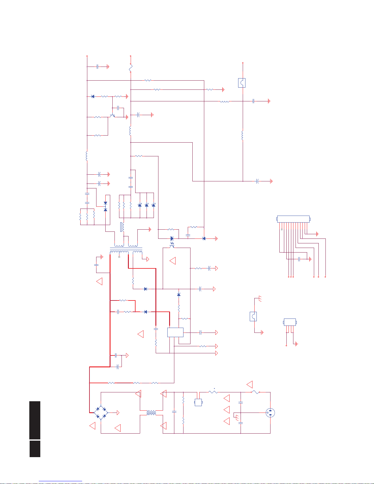
6.2 Power Board
Adapter (715G3974P01003001H)
Remark: Parts position can be searched by using FIND function in PDF.
D904 SR504-30
1 2
DIM
NC/C930
NC/100N 50V
+
C918
470UF 35V
R910
10K 1/4W
CN901
SOCKET
12
3
R930
10K +-1% 1/10W
FB901
BEAD
1 2
R919
100 OHM 1/4W
NC/C936
NC/0.47UF 50V
!
R908
8.87K 1/8W
R903
6R8 +-5% 1/8W
R961 100 OHM 1/4W
!
REV:B ADD
CN903(USB
⿄ɖ
)
+5V
L904
3.5uH
R909
4.7M OHM +-5% 1/4W
C935
1000P 500V
C910
1000P 500V
R911
91KOHM +-1% 1/8W
C906
NC/1500PF2KV
C924
100N 50V
t
NR901
NTCR
12
+
C905
100uF M 450V
067G 40Z10115L
VOL
R904
100K OMH 2W +-5%
!
R947
470OHM2W
R913
1.5M OHM 1% 1/4W
R926
1K 1/10W 1%
C912
1000P 500V
C929
1000P 500V
NC/L906
NC/2.2uH
!
F901
FUSE
F902
JUMPER
12
C907
1500PF2KV
-
+
BD901
D2SB80 2A/800V
2
1
3
4
C901
1000pF 250VAC
D903 SR504-30
1 2
R927
10K 1/10W 1%
+5V1
!
D906
MBRF10100CT
1
2
3
!
R920
100 OHM 1/4W
R924
200OHM +-5% 1/8W
+5V1
R906
10R 1/8W 5%
R907
4.7M OHM +-5% 1/4W
R905
NC
+16V
R940
NC
C902
1000pF 250VAC
R912
0 OHM 1/4W
!
IC901
TOP266EN
1
234
5 7
V
X
C
F
SD
IC904
KIA431A-AT/P
C900
3300PF/250V
C922
NC
CN902A
CONN
123456789
101112
13
D901
FR107
D905 SR504-30
1 2
!
L901
30mH
1
4
2
3
+
C908
22uF 50V
C923
100N 50V
L905
3.5uH
C932
1N 50V
T901
POWER X'FMR
4
8
12
5
6
2
1
7
9
R925
NC
!
!
+5V
ZD901
MTZJ T-72 22B
ON/OFF
!
D902
FR103
93G 6038T52T
R918
100 OHM 1/4W
R946
470OHM2W
FB902
12
CN903
CONN
123
4
L903
3.5uH
+
C916
1000uF 10V
CHANGE
JUMP
WIRE
+
C917
470UF 35V
R962 100 OHM 1/4W
R943
470OHM +-5% 1/8W
CN905
CONN
1
2
L
N
R902
1MOHM +-5% 1/4W
C903
0.22UF275V
!
R935 100 OHM 1/4W
F903
FUSE 4A 250V
+
C909
22uF 50V
+16V
R901
1MOHM +-5% 1/4W
ZD902
MTZJ T-72 22B
+
C915
470uF 16V
IC903
PC123X2YFZOF
12
43
MUTE
Q903
KTD1028
R939
1K 1/8W
C931
100N 50V
Power
23
Meridian 3
Remark: Parts position can be searched by using FIND function in PDF.
+
C615
220uF16V
D601
1N4148-B4006
CN603
CONN
123
4
R617
1K 1/10W 5%
CN602
NC/CONN
12345
6
+
C614
220uF16V
C610
100pF 50V
C612
0.1uF 16V
HS4
HEAT SINK(I C 601)
1
2
LOUT+
R615
330R 1/6W 5%
VOL
Lin
R60110K 1/10W 5%
+5V1
R618
1K 1/10W 5%
C609
1U 25V
R614
10K 1/10W
C603
470nF 16V
R621
4.7K 1/10W
R607 15K
SCALER I N R
C602
470nF 16V
ROUT-
C611
100pF 50V
Q608
PMBT3904
R602
10K 1/10W 5%
SCALER OU T RR605 12K
C613
0.1uF 16V
R609
100K 1/10W
+5V1A
SCALER I N R
C608
1U 25V
R625
0R05 1/10W
SCALER I N LC601
470N 16V
R6080R051/8W
R613
330R 1/6W 5%
R606 15K
R611
56K1/10W
+5V1A
LOUT-
R603
10K 1/10W 5%
Rin
+5V1A
R610
10K 1/10W 5%
R619
10K 1/10W
CN604
CONN
12345
IC601
APA2071JI-TUG 3. 1W
1234567
8 9
10111213141516
SHUTDOWN
BYPASS
RINN
GND
GND
LINN
VOLUME
SE/BTL
LOUT-
VDD
LOUT+
GND
GND
ROUT+
VDD
ROUT-
ROUT+
MUTE
SCALER I N L
R612
750OHM +-5% 1/10W
SCALER OU T L
SCALER OU T R
R626
0 OHM +-5% 1/8W
R620
1K 1/10W 5%
C606
470N 16V
+
C604
100uF25V
IC with Heat-sink(90G6295-3)
+5V1A
SCALER OU T L
CN601
JACK
12354
+
C607
100uF25V
R616
100K 1/10W 5%
FB601
BEAD
1 2
Q607
MMBT3906
R604 12K
FB602
BEAD
1 2
Audio
!
24
Meridian 3
Converter (715G4107P02000004S)
Remark: Parts position can be searched by using FIND function in PDF.
C803
100N 50V
C801
100N 50V
R848
33R 1/10W 5%
R841 1 OHM 1/10W
VIN
R823
4.7K 1/8W
IC802
TA9690GN
123456789
101112 13
1415161718192021222324
PWM
ISEN1
ISEN2
ISEN3
ISEN4
GNDA
ISEN8
ISEN6
ISEN7
OVP
ISET
RT ENA
ISW
ISEN5
LDR
VREF
GNDP
VIN
SEL
COMP
SSTCMP
NC
STATUS
R842
N.C
R842
20mA
VIN
Vout
F801
0R05 1/4W
27K
C807
2.2U16V
IC801
TA9690GN
123456789
101112 13
1415161718192021222324
PWM
ISEN1
ISEN2
ISEN3
ISEN4
GNDA
ISEN8
ISEN6
ISEN7
OVP
ISET
RT ENA
ISW
ISEN5
LDR
VREF
GNDP
VIN
SEL
COMP
SSTCMP
NC
STATUS
R831 1 OHM 1/10W
C811 NC
R803
1K 1/10W 5%
C806
2U2 25V
OVP2
R805 160KOHM +-1%1/10W
56K
R826 1 OHM 1/10W
R807
10R 1/10W 5%
+
C804NC
C814
100P 50V
R825
0R05 1/4W
R827 1 OHM 1/10W
R819
100K 1/10W 5%
CN801
CONN
12345
+
C813
100uF 50V
R838 1 OHM 1/10W
R840 1 OHM 1/10W
+12V
25mA
CN803
CONN
123456789
101112
13 14
C808
0.47uF 16 V
150K
R813 10K 1/10W 5%
Q801
APM8005KCTRG
123
4 5
678
S1G1S2
G2 D2
D2D1D1
CN802
CONN
1
2
R815
R814
10 OHM 1/10W
C809
2.2U16V
ENA
R806
10K 1/10W 5%
R824
36KOHM +-1% 1/8W
R830 1 OHM 1/10W
R804
30K +-1% 1/10W
R818
NC
R847
33R 1/10W 5%
R810
1K 1/10W 5%
Iout
R829 1 OHM 1/10W
R815
30K +-1% 1/10W
R816 160KOHM +-1%1/10W
R835 1 OHM 1/10W
R846
33R
56K
C812
100PF 50V
R809
100K 1/10W 5%
Vout
R844 NC
R811
0R05 1/10W
27K
R821 10K 1/10W 5%
R849
33R
ZD801
B310B
R812
100 OHM 1/10W
DIM
R836 1 OHM 1/10W
C805
0.47uF 16V
OVP1
R801
0.15 OHM +-1% 1/4W
R820
100 OHM 1/10W
R833 1 OHM 1/10W
VIN
R802
NC
R837 1 OHM 1/10W
R834 1 OHM 1/10W
R843
CN804
CONN
123456789
101112
13 14
R843 N.C
OVP1
R839 1 OHM 1/10W
56K
R808
NC
R832 1 OHM 1/10W
L801
33UH
R822
1M 1/8W 5%
R817
10K 1/10W 5%
R804
OVP2
150K
R828 1 OHM 1/10W
R845
100 OHM 1/10W
56K
+
C810
33UF 100V
25
Meridian 3
6.3 USB Board (715G4597T01000004S)
Remark: Parts position can be searched by using FIND function in PDF.
12
34
CN752
USB CONN V TY PE
123
4
6 5
78
C772
4.7UF 16V
DM22
C762
100N 16V
C761
100N 16V
C722
150pF 50V
UGND
R758
NC/10K 1/10 W 5%
USB5V
+
C777
100uF/16V
FB753
120 OHM
1 2
C711
1N 50V
R765
10K 1/16W 5%
Power Regulator
UGND
DM44
R713
6.8K +-1% 1/16W
R782
NC
R752
51K 1/16W 5%
+
C716
470uF 10V
L753
90OHM
1
4
2
3
UGND
UGND
UGND
+
C776
100uF/16V
DP4
C785
10uF 25V
UGND
R788
NC/10K 1/ 10W 5%
UGND
DM0
FB761
120OHM
1 2
t
F752
PTCR
12
U5V
UGND
DM3
UGND
UGND
DM2
FB702
30OHM
R778
15KOHM 1/16W
D701
SR34
1 2
UGND
UGND
DP3 DM2
C763
100N 16V
UGND
UGND
FB703
0R05 1/10W
R759
NC/10K 1/10 W 5%
/OC4
U705 MP1584EN
123
45
678
9
SW
EN
COMP
FBGND
FREQ
VIN
BST
Thermal P a d
USB_power=16V
ZD752
NC/VPORT0603 102M V05
1 2
VBUS4
USB3.3V
USB3.3V
FB752
120 OHM
1 2
FB757
120 OHM
1 2
FB751
120 OHM
1 2
USB5V
C723
10uF 25V
VBUS2
DP2
C767
100N 16V
C778
100N 16V
1234
CN756
USB CONN
123
4
6 5
R773
10K 1/16W 5%
USB3.3V
USB5V
D703
SR34
1 2
VBUS1
DM4
C713
100N 16V
U5V
DM11
/OC2
EEPROM NC: R818~820 pull low
UGND
USB5V
USB3.3V
UGND
/OC4
C787
0.1uF 16V
R780
100K 1/10W
UGND
VBUS_DET
DM3
U751 A P1117E33LA
1
23
VSS
VOUTVIN
C757
100N 16V
UGND
+
C784
270UF 25V
DM3
C756
100N 16V
C712
100N 50V
R764
10K 1/16W 5%
X751
24.000MHZ
12
UGND
VBUS0
ZD751
NC/VPORT0603 102M V05
1 2
ZD702
NC/RLZ6.2B
1 2
UGND
ZD753
1 2
UGND
DP1
VBUS3A
DM33
/OC1
C768
100N 16V
USB3.3V
C780
100N 16V
C771
100N 16V
DP4
L751
90OHM
1
4
2
3
C760
NC
ZD756
1 2
R775
10K 1/16W 5%
DM4
DP2
t
F753
PTCR
12
U753
NC/ M24C0 2-WMN 6TP
123
45
678
A0A1A2
GNDSDA
SCLWPVCC
UGND
ZD754
1 2
USB3.3V
UGND
FB758
120 OHM
1 2
UGND
VBUS1
UGND
UGND
UGND
UGND
UGND
R762
100K 1/16W 5%
VBUS0
UGND
DP22
VBUS4
CN751
CONN
123
EEPROM mount: R812~814 pull hi
USB5V
L754
90OHM
1
4
2
3
VBUS2
UGND
1234
CN755
USB CONN
123
4
6 5
UGND
R772
10K 1/16W 5%
USB_POWER
C783
0.1UF50V
C717
100N 16V
UGND
C710
1N 50V
UGND
DP0
UGND
UGND
/OC1
C775
100N 16V
t
F754
PTCR
12
UGND
UGND
C715
100N 50V
FB756
120 OHM
1 2
R776
15KOHM 1/16W
R767
NC/10K 1/ 10W 5%
R771
1MOHM 1/16W +/-5%
VBUS0
UGND
Upst re am
Dow ns tr eam 1
Dow ns tr eam 2
Dow ns tr eam 3
Dow ns tr eam 4
EEPROM/ Con f ig
Common
U752 USB2514B-AEZG
31302
4
7
9
1
3
6
8
27
12
16
18
20
13
17
19
21
352224
25
33
32
26
28
11
2334293615
14
37
5
10
USBUP_DP
USBUP_DM
USBDN1_DP
USBDN2_DP
USBDN3_DP
USBDN4_DP
USBDN1_DM
USBDN2_DM
USBDN3_DM
USBDN4_DM
VBUS_DET
PRTPWR1
PRTPWR2
PRTPWR3
PRTPWR4
OCS1
OCS2
OCS3
OCS4
RBIAS
SDA/SMBDATA/NON _REM1
SCL/SMBCLK/C FG_SEL0
HS_IND/CFG_SEL1
XTAL1/CLKIN
XTAL2/CLKIN_EN
RESET
LOCAL_PWR/NON_REM0/SUSP_IND
TEST
VDD33
VDDA18PLL
VDDA33
VDDA33/VDD33PLL
VDD33CR
VDD18
VSS(FLAG)
VDDA33
VDDA33
DM1
/OC3
C790
100N 16V
L752
90OHM
1
4
2
3
R774
10K 1/16W 5%
R769
10K 1/16W 5%
R760
NC/10K 1/10 W 5%
R789
NC/10K 1/ 10W 5%
R786
NC/10K 1/ 10W 5%
R766
11.5K +-1% 1/16W
+
C781
100uF/16V
UGND
+
C753
100uF/16V
DP1
1234
5678
CN754
CONNNECTOR
123
4
657
8
11
12
9
10
C755
1uF 10V
FB760
120OHM
1 2
R753
100K 1/16W 5%
DP11
C754
100N 16V
C764
100N 16V
C758
100N 16V
UGND
DP4
/OC2
UGND
DM4
+
C779
100uF/16V
UGND
C714
1N 50V
UGND
DP3
C766
4.7UF 16V
R714
1.3K 1%
UGND
FB755
120 OHM
1 2
t
F751
PTCR
12
UGND
R777
15KOHM 1/16W
R787
NC/10K 1/ 10W 5%
ZD755
NC/VPORT0603 102M V05
1 2
DP44
C759
100N 16V
+
C752
100uF/16V
UGND
DM1
C770
33P 50V
C765
33P 50V
L701 22UH
R726
100K 1/16W
R751
10K 1/16W 5%
L755
90OHM
1
4
2
3
UGND
ZD758
NC/VPORT0603 102M V05
1 2
UGND
UGND
FB754
120 OHM
1 2
USB3.3V
VBUS3
C773
100N 16V
DP3
C791
100N 16V
2010/1/25
C769
100N 16V
UGND
C782
100N 16V
C751
100N 16V
UGND
VBUS4A
/OC3
DP33
ZD757
NC/VPORT0603 102M V05
1 2
R727
300K
R779
15KOHM 1/16W
VBUS3
C774
4.7UF 16V
USB 2514
!
26
Meridian 3
Remark: Parts position can be searched by using FIND function in PDF.
GND
Headset_L
CN004
PHONEJACK
1
235
4
Headset_L
EAR_Det
Headset_R
CN002
CONN
12345
67
EAR_Det
Headset_R
Earphone
27
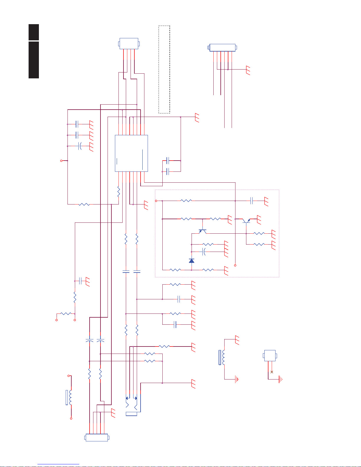
Meridian 3
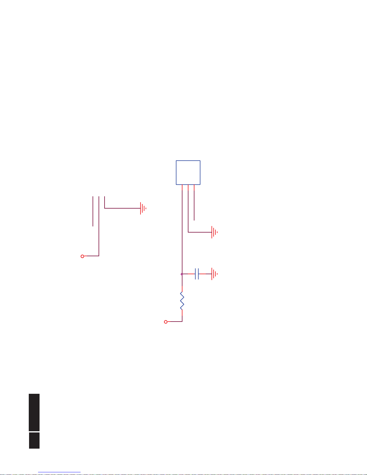
6.4 IR Board
715G4594T01000004S
Remark: Parts position can be searched by using FIND function in PDF.
VCC
VCC_IN
ZD053NC/UDZSNP5.6B
1 2
C051
10uF 16V
C052
100N 16V
PS_ON
PS_OUTPUT
CN052
CONN
12345
67
R059
100K 1/16W 5%
R064
100OHM1/16W
R056
0R05 OHM
LED051
LED
12
R051
NC/ 0R 05 1/ 16W
VCC
PS_ON
C054
100N 16V
IR_RX
PS_DISTANCE
IR_RX
C055
100N 16V
C053
100N 16V
VCC
R052
33R 1/8W 5%
PS_OUTPUT
Q051
AO3401A
R055
10K 1/16W 5%
PS_DISTANCE
R061
NC
VCC
Q052
SST2222A
R062
10K 1/16W 5%
PS_OUTPUT
R053
33R 1/8W 5%
U052
AS358MTR-E1
123
45
678
1OUT
1IN-
1IN+
GND2IN+
2IN-
2OUT
VCC+
CN051
CONN
123
45
C057
100N 16V
PS_DISTANCE
R058
100K 1/16W 5%
PS_ON
VCC_IN
ZD052NC/UDZSNP5.6B
1 2
VCC
VCC
C056
100N 16V
C058
100N 16V
ZD051
NC/UDZSNP5.6B
1 2
PS_DISTANCE
R060
NC
R054
1K 1/16W 5%
VCC_IN
R063
1K 1/16W 5%
R057
100K 1/16W 5%
U051
PIC12F615-I/SN
123
4 5
678
VDD
GP5/T1CKI/P1A*/OSC1/CLKIN
GP4/AN3/CIN1-/T1G/P1B*/OSC2/CLKOUT
GP3/T1G*/MCLR/VPP GP2/AN2/T0CKI/INT/COUT/CCP1/P1A
GP1/AN1/CIN0-/VREF/ICSPCLK
GP0/AN0/CIN+/P1B/ICSPDAT
VSS
ZD054NC/UDZSNP5.6B
1 2
Sensor TX
!
28
Meridian 3
715G4595R01000001S
Remark: Parts position can be searched by using FIND function in PDF.
IR_RX-1
VCC
R065
100R 1/ 8W 5%
C059
0.1uF 50V
IR_RX-1
VCC
U053
KSM-603TM2M
1
2
3
VOUT
GND
VCC
Sensor RX
 Loading...