

Page 1
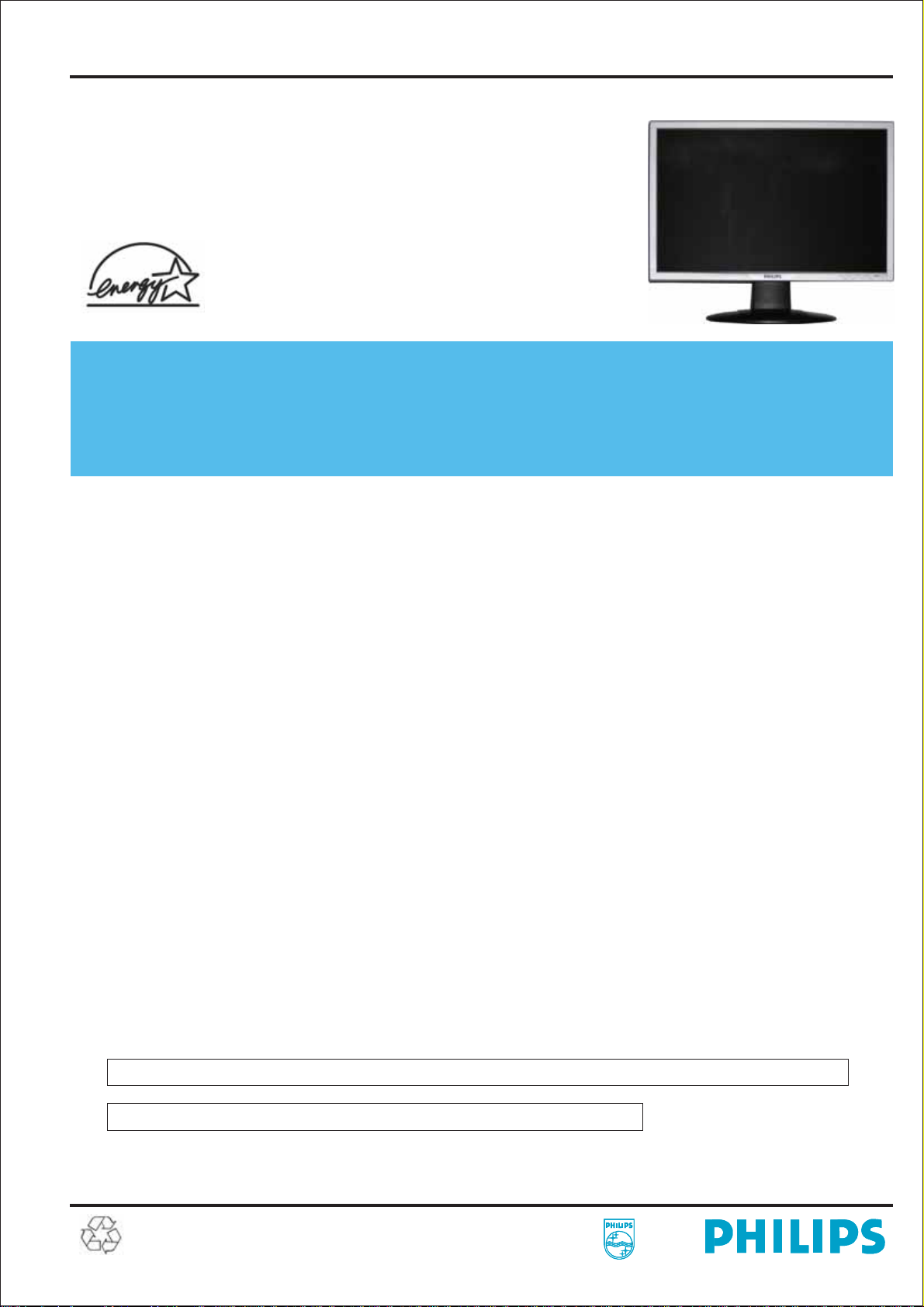
22” TFT LCD COLOR MONITOR
ServiceService
220VW8FB/00
220VW8FB/93
ServiceService
220VW8FB/96
ServiceService
Service Manual
TABLE OF CONTENTS
Description
Page
Description
Page
Important Safety Notice .............................................
Technical Data & Power Management .......................
Connection to PC .......................................................
OSD Menu Control Level Structure ...........................
Advanced OSD Adjustment .......................................
OSD Attention Signal .................................................
Safety and troubleshooting information ....................
Definition of Pixel Defects ..........................................
Wiring Diagram ..........................................................
Mechanical Instructions .............................................
F/W Upload Instructions ............................................
DDC Instructions ........................................................
DDC DATA .................................................................
Safety Instructions, Warnings and Notes ........
http://www.wjel.net
ANY PERSON ATTEMPTING TO SERVICE THIS CHASSIS MUST FAMILIARIZE HIMSELF WITH THE CHASSIS
AND BE AWARE OF THE NECESSARY SAFETY PRECAUTIONS TO BE USED WHEN SERVICING ELECTRONIC
EQUIPMENT CONTAINING HIGH VOLTAGES.
2
3~4
5
6
7
8
9
10~11
12
13~15
16~17
17~19
20
21
...........
SAFETY NOTICE
Block Diagram ...........................................................
Scaler Board Schematic Diagram ..............................
Power Board Schematic Diagram ..............................
Button Board Schematic Diagram .............................
Scaler Board Layout Side View .................................
Power Board Layout Side View .................................
Button Board Layout Side View .................................
Exploded View ...........................................................
Recommended Parts List ..........................................
Spare Parts List .........................................................
Different Parts List .....................................................
General Trouble Shooting Guide ...............................
General Product Specification ...................................
Safety Check Process ...............................................
22
23~27
28~29
30
31~32
33~34
35
36
37~39
40~41
42
43~57
58~70
71
CAUTION: USE A SEPARATE ISOLATION TRANSFORMER FOR THIS UNIT WHEN SERVICING.
REFER TO BACK COVER FOR IMPORTANT SAFETY GUIDELINE.
Subject to modification
Oct. 23th. 2007
EN :
Page 2
2
220VW8 LCD
Important Safety Notice
Proper service and repair is important to the safe, reliable
operation of all Philips Consumer Electronics Company**
Equipment. The service procedures recommended by Philips
and described in this service manual are effective methods of
performing service operations. Some of these service
operations require the use of tools specially designed for the
purpose. The special tools should be used when and as
recommended.
It is important to note that this manual contains various
CAUTIONS and NOTICES which should be carefully read in
order to minimize the risk of personal injury to service
personnel. The possibility exists that improper service
methods may damage the equipment. It is also important to
understand that these CAUTIONS and NOTICES ARE NOT
EXHAUSTIVE. Philips could not possibly know, evaluate and
advise the service trade of all conceivable ways in which
service might be done or of the possible hazardous
consequences of each way. Consequently, Philips has not
undertaken any such broad evaluation. Accordingly , a
servicer who uses a service procedure or tool which is not
recommended by Philips must first satisfy himself thoroughly
that neither his safety nor the safe operation of the equipment
will be jeopardized by the service method selected.
* * Hereafter throughout this manual, Philips Consumer
Electronics Company will be referred to as Philips.
FOR PRODUCTS CONTAINING LASER :
DANGER - In visible laser radiation when open.
AVOID DIRECT EXPOSURE TO BEAM.
CAUTION - Use of controls or adjustments or
performance of procedures other than
those specified herein may result in
hazardous radiation exposure.
CAUTION - The use of optical instruments with this
Product will increase eye hazard.
TO ENSURE THE CONTINUED RELIABILITY OF THIS
PRODUCT, USE ONLY ORIGINAL MANUFACTURER'S
REPLACEMENT PARTS, WHICH ARE LISTED WITH
THEIR PART NUMBERS IN THE PARTS LIST SECTION
OF THIS SERVICE MANUAL.
Take care during handling the LCD module with backlight
unit
WARNING
Critical components having special safety characteristics are
identified with a by the Ref. No.in the parts list and
enclosed within a broken line*
(where several critical components are grouped in one
area) along with the safety symbol on the schematics or
exploded views.
Use of substitute replacement parts which do not have the
same specified safety characteristics may create shock, fire,
or other hazards.
Under no circumstances should the original design be
modified or altered without written permission from Philips.
Philips assumes no liability , express or implied, arising out of
any unauthorized modification of design.
Servicer assumes all liability .
http://www.wjel.net
* Broken Line
- Must mount the module using mounting holes
four corners.
- Do not press on the panel, edge of the frame
electric shock as this will result in damage to the screen.
- Do not scratch or press on the panel with any sharp
such as pencil or pen as this may result in
panel.
- Protect the module from the ESD as it may damage
electronic circuit (C-MOS).
- Make certain that treatment persons body are
through wrist band.
- Do not leave the module in high temperature and in
of high humidity for a long time.
- Avoid contact with water as it may a short circuit
the module.
- If the surface of panel become dirty, please wipe it
a soft material.( Cleaning with a dirty or
damage the panel.)
arranged in
strongly or
damage to the
grounded
within
off with
rough cloth may
objects,
the
areas
Page 3

Technical Data
220VW8 LCD
3
1. General Specification
1.1 Panel characteristic
Panel source
Screen type
Screen dimensions
CPT CLAA220WA01
Resolution
Outside dimensions
Pixel pitch (mm)
Color pixel arrangement
Display surface
Color depth
Backlight
Active area (mm)
View angle (CR>10)
Contrast ratio
White luminance
Color gamut
Response time
1.2 Scanning frequencies
Horizontal scan range
Vertical scan range
1.3 Video
Video dot rate
Input impedance
(Analog signal input)
- video
- Sync
CLAA 220WA01
: CPT
: TN+film
: 22 inches (diagonal) 16:10
: 1680 x 1050 (WXGA+)
: 493.7 (W) x 320.1 (H) x 16.5 (D)
: 0.276 x 0.276
: R. G. B. Vertical Stripe
: Hard-coating (3H), Non-glare type
: 16.7M colors
: 4 lamps
: 494.94 (H) x 290.58(V)
: >= 170 (H)/160(V) (typical)
:>=1000:1
: >= 300 nits (7.0mA)
:>=72%
:5ms
: 30 - 93 K Hz (automatic)
: 56 - 76 Hz (automatic)
: < 205 M Hz (Over 165MHz,
Warning message will show up)
:75ohm
: 2.2K ohm
Input signal levels
Sync. Input signals
Input impedance (Digital)
Video interface
1.4 Physical characteristics
Unit dimensions
- Width
- Height
- Depth
Packed unit dimensions
- Width
- Height
- Depth
Packed unit dimensions
(China only)
- Width
- Height
- Depth
Weight (monitor only)
Title angel
Swivel angel
Height adjustment
Portrait display
: 700 mVpp
: Analog R/G/B separate inputs
Separate horizontal and vertical /
Composite (H+V) TTL level,
Sync On Green (SOG) sync
0.3Vp-p Negative
: Signal TMDS link
(3 channels : Rx0 & Rx1 & RX2-/+)
: Both Analog and Digital input.
It can be switching via OSD option.
: 513.8 mm
: 416.2 mm
: 213.6 mm
: 565 mm
: 174 mm
: 472 mm
: 567 mm
: 189 mm
: 480 mm
: 5.3 Kg (Including I/F cable 240g)
:-5°+2/-0°(forward )
+25°+0/-3°(backward )
: nil
: nil
: nil
AC input: - voltage
- frequency
Power consumption
Ambient temperature
Operating
- Temperature
- Humidity
http://www.wjel.net
- Altitude
- Air pressure
Storage
- Temperature
- Humidity
- Altitude
- Air pressure
System MTBF
:AC90-264V,
:50/60 2Hz
: < 50W maximum, 45W (typ)
:40
0 to degree C
: 5 to 35 degree C
: 10% to 85% (max.)
: 0 - 3658 m
: 600 - 1000 mBAR
(Recommend at 5 to 35 degree C,
Humidity less then 60%)
: -20 to 60 degree C
: 95% max
: 0 - 12192 m
: 300 - 1100 mBAR
: 50,000 Hrs
+
Page 4
4
220VW8 LCD
Technical Data
2. Pin Assignment
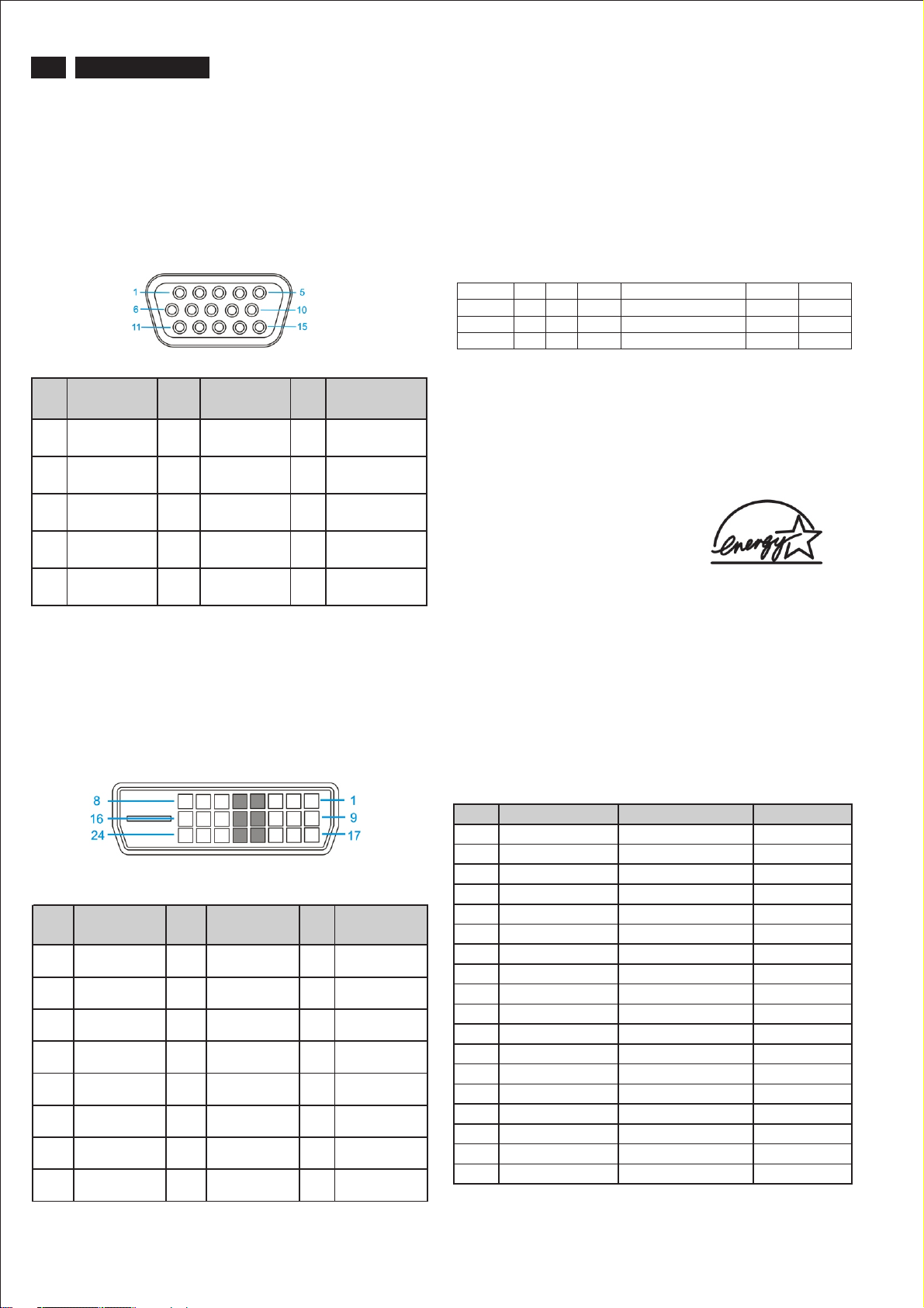
2.1 PC analog video input with D - sub connector.
Connector type of analog signal cable :
D - Sub male with DDC2B pin assignment.
Blue connector with thumb-operated jackscrews.
Pin assignment :
PIN
No.
Signal
Assignment
PIN
No.
Signal
Assignment
PIN
No.
Signal
Assignment
1 Red 6 Red GND 11 Sense (GND)
2 Green/ SOG 7 Green GND 12 Bi-directional
data
3 Blue 8 Blue GND 13 H/H+V sync
4 Sense (GND) 9 DDC +3.3V or
14 V-sync
+5V
5 N/A 10 Logic GND 15 Data clock
2.2 PC digital video input with DVI-D connector.
Automatic Power Saving
If you have VESA / DPMS compliance display card or software
installed in your PC, the monitor can automatically reduce
power consumption when power saving function active. And if
an input from keyboard, mouse or other devices is detected,
the monitor will automatically wake up. The following table
shows the power consumption and signaling of this automatic
power saving feature:
Mode HSYNC VSYNC Video Pwr-cons. Indication Rec. time
Power- On On On acti ve < 50W ( <54W : for audio model ) G reen LED --
Off Off O ff bla nked < 1 W Amber LED < 5 s
DC Power Off N/A < 1 W LED Off
This monitor must comply with the Microsoft On Now
specification, with two power management states, as defined
by the VESA DPMS document. And must appropriately display
the DPMS states. Also comply with Environmental Protection
Agency (EPA) Energy Star and TCO03 power management
standard strictly.
ENERGY STAR is a U.S. Registered mark. AS AN ENERGY
STAR PARTNER, PHILIPS HAS DETERMINED THAT THIS
PRODUCT MEETS THE ENERGY STAR GUIDELINES OF
ENERGY EFFICIENCY.
Connector type of DVI-D signal cable :
DVI-D male with DDC2B pin assignment.
White connector with thumb-operated jackscrews.
Pin assignment :
PIN
Signal
No.
Assignment
1 T.M.D.S.
data2-
2 T.M.D.S.
data2+
3 T.M.D.S.
data2 shield
4 No Connect 12 No Connect 20 No Connect
5 No Connect 13 No Connect 21 No Connect
6 DDC clock 14 +5V Power 22 T.M.D.S clock
7 DDC data 15 Ground (for
8 No Connect 16 Hot plug
PIN
Signal
No.
Assignment
9 T.M.D.S.
data1-
10 T.M.D.S.
data1+
11 T.M.D.S.
data1 shield
+5V)
detect
PIN
Signal
No.
Assignment
http://www.wjel.net
17 T.M.D.S.
data0-
18 T.M.D.S.
data0+
19 T.M.D.S.
data0 shield
shield
23 T.M.D.S.
clock+
24 T.M.D.S. clock-
Data Storage
Factory preset mode:
This monitor has 18 factory-preset modes as indicated in the
following table:
Item Resolution H. freq/ V. freq Standard
1 640*350 31.469 KHz/70.086 Hz
2 720*400 31.469 KHz/70.087 Hz
3 640*480 31.469 KHz/59.94 Hz
4 640*480 35 KHz/67 Hz
5 640*480 37.5 KHz/75 Hz
6 800*600 35.0156 KHz/56.25 Hz
7 800*600 37.879 KHz/60.317 Hz
8 800*600 46.875 KHz/75 Hz
9 1024*768 48.363 KHz/60.004 Hz
10 1024*768 60.023 KHz/75.029
11 1280*1024 63.981 KHz/60.02 Hz
12 1280*1024 79.976 KHz/75.025 Hz
13 1440*900 55.469 KHz/59.901 Hz
14 1440*900 55.935 KHz/59.887
15 1440*900 70.635 KHz/74.984 Hz
16 1920*1080 66.587 KHz/60 Hz
17 1680*1050 65.29 KHz/60 Hz
18 1680*1050 65.29 KHz/60 Hz
IBM VGA 10H
IBM VGA 3H
IBM VGA 12H
MACINTOSH
VESA
VESA
VESA
VESA
VESA
VESA
VESA
VESA
VESA
VESA
VESA
CVT 2.3 MA-R
CVT 1.76 MW
CVT 1.76 MW -R
Page 5
Connection to PC
220VW8 LCD
5
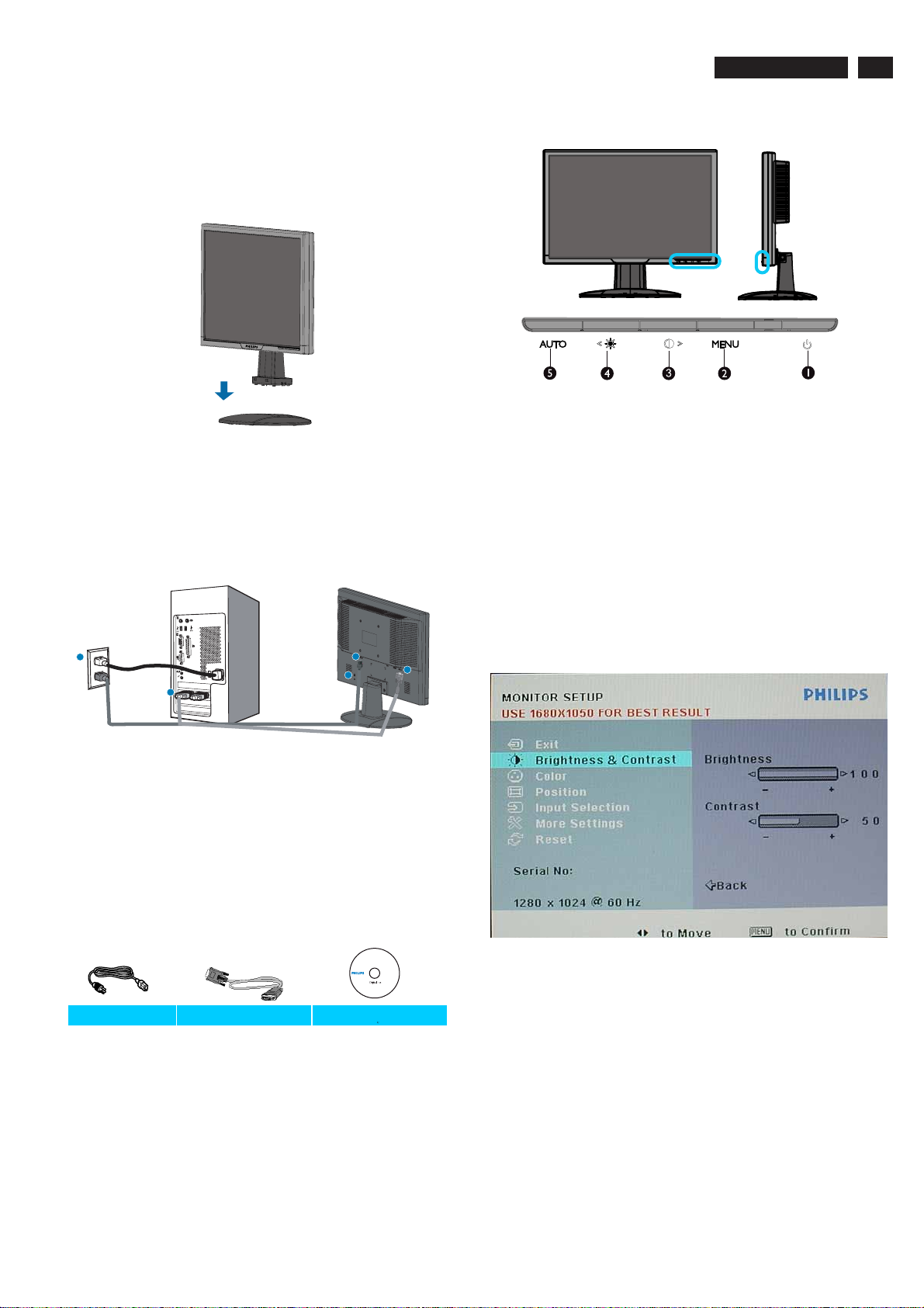
1. Connection to PC
Please follow the steps to connect your LCD Monitor to PC.
a. Assembly LCD Monitor with base
b. Connect to PC
1). Turn off your computer and unplug its power cable.
2). Connect the monitor signal cable to the video connector
on the back of your computer.
3). Plug the power cord of your computer and your monitor
Into a nearby outlet.
4). Turn on your computer and monitor. If the monitor
displays an image, installation is complete.
2. Function key definition
(1) To switch monitor’s power on and off
(2) To access OSD menu
(3) Hot key of contrast adjustment and to adjust OSD
value up when OSD menu is active
(4) Hot key of brightness adjustment and to adjust OSD
Value down when OSD menu is active
(5) Automatically adjust the horizontal position, vertical
position, phase and clock settings
3. Description of the On Screen Display
1
2
Port definition:
(1) AC power input
(2) VGA input
(3) Kensington anti-thief lock
Set your Monitor at 1680*1050@60Hz for best performance.
c. Accessory Pack
1
3
2
http://www.wjel.net
Power cord VGA cable EDFU CD
D
On-Screen Display(OSD) is a feature in all Philips LCD
monitors. It allows and end user to adjust screen performance
or select functions of the monitors directly through an on-screen
instruction window. A user friendly on screen display interface is
shown as below:
Basic and simple instruction on the control keys.
According to the above OSD structure, users can :
<>
press or buttons to move the cursor,
MENU
press button to confirm the choice or change,
press button to adjust the value,<>
press button to save the changes.
press button to automatically adjust the horizontal
position, vertical position, phase and clock setting.
or
MENU
AUTO
Page 6
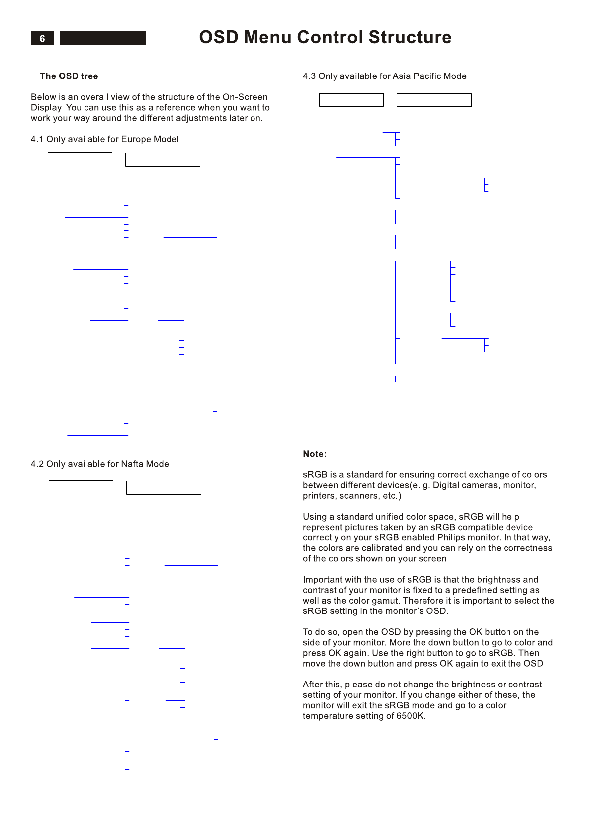
4.
200AW8 LCD
200WS8 LCD
220VW8 LCD
60
Main Menu (1st Level)
Exit
Brightness & Contrast Brightness
Color
Position
Input selection
More Settings
Sub Menu (2nd Level)
Contrast
Back
Original Color
9300K
6500K
User Define
Back
Horizontal
Vertical
Back
Analog
Digital
Back
Language English
Phase/Clock Phase
OSD Settings Horizontal
Back
oNteseR
Yes
Español
Français
Deutsch
Italiano
Русский
Back
Clock
Back
Red
Green
Blue
Vertical
Back
Main Menu (1st Level)
Exit
Brightness & Contrast Brightness
Color
Position
Input selection
More Settings
Sub Menu (2nd Level)
Contrast
Back
Original Color
9300K
6500K
User Define
Back
Horizontal
Vertical
Back
Analog
Digital
Back
Language English
Phase/Clock Phase
OSD Settings Horizontal
Back
oNteseR
Yes
Español
Français
Deutsch
Italiano
中文
Back
Clock
Back
Red
Green
Blue
Vertical
Back
Main Menu (1st Level)
Exit
Brightness & Contrast Brightness
Color
Position
Input selection
More Settings
Sub Menu (2nd Level)
Contrast
Back
Original Color
9300K
6500K
User Define
Back
Horizontal
Vertical
Back
Analog
Digital
Back
Language English
Phase/Clock Phase
OSD Settings Horizontal
Back
oNteseR
Yes
Red
Green
Blue
http://www.wjel.net
Español
Français
Portugues
中文
Back
Clock
Back
Vertical
Back
Page 7
Advanced OSD Adjustment
220VW8 LCD
7
Advanced OSD Adjustment
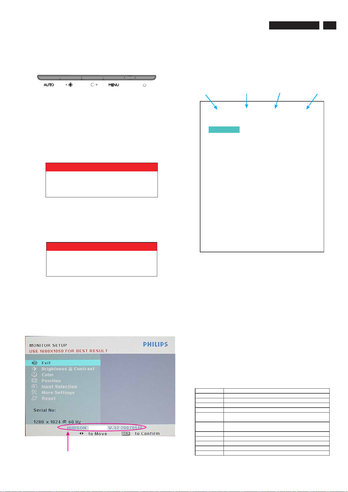
1. Front control panel
2. To Lock/Unlock OSD function
The OSD function can be locked by pressing button
MENU
for more than 10 seconds, the screen shows following
windows for 3 seconds.
Every time when you press any button, this message
appears on the screen automatically.
ATTENTION
OSD MAIN CONTROLS LOCKED
Locked OSD function can be released by pressing
button for more than 10 seconds. While press button
MENU
MENU
for OSD unlocked purpose, the screen will keep showing
OSD MAIN MENU LOCKED until OSD function unlocked and
screen automatically shows following window for 3 seconds.
4. Entering Burn-in mode and others
If you access into factory mode, press or button to move
<>
the cursor on the message bar of “ HUSDON 220VW8 V.32”.
Then press to confirm, OSD menu will convert into
MENU
another format as below:
BIOS Revision Scaler IC Type Panel Type BIOS issued date
V.32 05/18/07
Burn in
AutoColor
Con 50
Bri 100
Gain R 88 G 91 B 88
Offset R 121 G 131 B 131
sRGB R 97 G 98 B 82
9300K R 91 G 94 B 95
6500K R 97 G 98 B 82
Color Update
Fatory Reset
CLAA220WA01TSUMU58WHJ
Off
ATTENTION
OSD MAIN CONTROLS UNLOCKED
3. Access Factory Mode
To hold and buttons, you can saw the LED
light flashing at this time. Then release the button and
Keep pressing the button. The monitor will power on
and LED light give out orange light. Press to bring up
AUTO POWER
AUTO
POWER
MENU
OSD menu for confirmation as below:
http://www.wjel.net
220VW8
If this message appeared, means monitor already entered
the factory mode.
Move the cursor by button, and press the
button
to change the burn-in mode from Off to ON.
MENU
or
<>
Leave factory mode by simply power off the monitor.
Warning
* If you only want to enter burn in mode, please don’t change
any other setting items as above listed.
* Unfortunately, if some settings has been changed by
unknown reasons or wrong operation. Please refer to the
chapter of “W/B Adjustment” to guide the operator how to
restore the default settings or do adjustment.
Appendix:
Explanation of above listed selections.
Selection Description
Burn in On/Off Enter Aging Mode
Auto Color Auto Color Adjustment
Con Contrast Adjustment
Bri Brightness Adjustment
Gain
Offset
sRGB sRGB Color Temperature Gain Value Adjustment
9300K 9300K Color Temperature Gain Value Adjustment
6500K 6500K Color Temperature Gain Value Adjustment
Color Update Save All of Color Temperature Gain Value
Factory Reset Memory Recall to Factory Default Settings
ADC Gain Value Adjustment
(Auto adjustment by H/W when implement Auto Color function)
ADC Offset Value Adjustment
(Auto adjustment by H/W when implement Auto Color function)
Page 8
8
220VW8 LCD
OSD Attention Signals
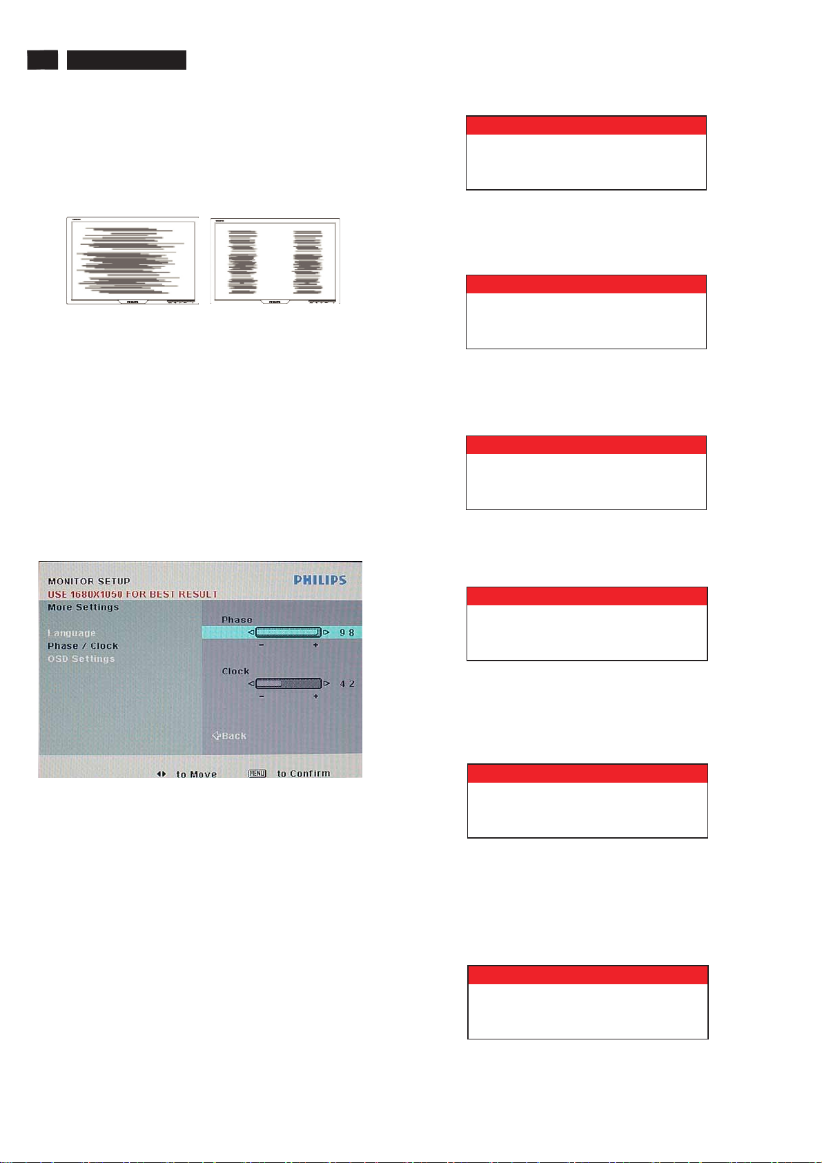
Clock & Phase Adjustment
Due to the different quality of video signal generated from
graphics cards. It is necessary to adjust CLOCK and PHASE
functions for the optimal video display of LCD monitor. So
maybe some flicker appeared as Fig.1 & 2.
Fig.1 Fig.2
Following steps will guide you to make correct adjustment of
CLOCK and PHASE:
a. Restart your computer.
b. Press to bring up OSD menu after the OS
c. Press or to select the option of and
then
d. Select the or adjustment items in submenu
e. Quit OSD by press button to save the settings.
MENU
(Operation System) boot up.
<>
press to bring up its submenu as shown in Fig.3.
MENU
Clock Phase
and press or to adjust.
(If the phenomenon as Fig.1, you should adjust “ ”)
(If the phenomenon as Fig.2, you should adjust “ ”)
<>
MENU
More Settings
Phase
Clock
ATTENTION
NO VIDEO INPUT
2. CANNOT DISPLAY THIS VIDEO MODE
This screen warns then the input frequency from the
computer is not a standard video mode or out of the monitor’s
scanning range. Please change the display results.
ATTENTION
CANNOT DISPLAY THIS VIDEO
MODE, CHANGE COMPUTER DISPLAY
INPUT TO 1680X1050 @60HZ
3. ENTERING SLEEP MODE
This screen appears when the monitor is about to enter the
sleep mode. Please press any key on the keyboard or click
the mouse to wake up the monitor and computer.
ATTENTION
ENTERING SLEEPING MODE
4. WAIT FOR AUTOMATIC ADJUSTMENT
This screen appears when you touch the button. It will
disappear when the monitor is properly adjusted.
AUTO
Fig.3
However, CLOCK and PHASE functions are only available
while analog video signal is supplied. Operating unit under
digital signal state, the video clock information can be
obtained from graphics cards directly. Therefor, it is
unnecessary to adjust these functions.
OSD Attention signal
The monitor will detect various display situation
automatically. When the monitor detects the problems, the
screen will show the different warning signals to remind you
what is happen to your monitor.
1. NO VIDEO INPUT
This screen appears if there is no video signal input. Please
check that the signal cable is properly connected to the video
cardofPCandmakesurePCison.
http://www.wjel.net
ATTENTION
WAITING FOR AUTOMATIC ADJUSTMENT
5. USE 1680*1050 FOR BEST RESULT
This message appears at the top of the OSD window when
the video mode input is not the recommended 1680*1050.
Other modes may result in some picture distortion. Please
adjust the video mode to 1680*1050 at 60Hz for best display
quality.
ATTENTION
USE 1680 X 1050 FOR BEST RESULT
6. SELECTED INPUT NOT AVAILABLE
When you select video input between analog or digital signal
via INPUT SELECTION function of OSD menu, if the one you
are selecting is not available, following message will appear
on the screen then switching back to the previous setting
automatically.
ATTENTION
SELECTED INPUT NOT AVAILABLE
Page 9
Safety and Troubleshooting Information
220VW8 LCD
9
Safety precautions and maintenance
WARNING: Use of controls, adjustments or
procedures other than those specified in this
documentation may result in exposure to shock,
electrical hazards and/or mechanical hazards.
Read and follow these instructions when connecting and using
your computer monitor:
a. To protect your display from possible damage, do not put
excessive pressure on the LCD panel. When moving your
monitor, grasp the frame to lift; do not lift the monitor by
placing your hand or fingers on the LCD panel.
b. Unplug the monitor if you are not going to use it for an
extensive period of time.
c. Unplug the monitor if you need to clean it with a slightly
damp cloth. The screen may be wiped with a dry cloth when
the power is off. However, never use alcohol, solvents or
ammonia-based liquids.
d. Consult a service technician if the monitor does not operate
normally when you have followed the instructions in this
manual.
e. The casing cover should be opened only by qualified service
personnel.
f. Keep the monitor out of direct sunlight and away from stoves
or any other heat source.
g. Remove any object that could fall into the vents or prevent
proper cooling of the monitor’s electronics.
h. Do not block the ventilation holes on the cabinet.
i. Keep the monitor dry. To avoid electric shock, do not expose
it to rain or excessive moisture.
j. When positioning the monitor, make sure the power plug and
outlet are easily accessible.
k. If turning off the monitor by detaching the power cable or DC
power cord, wait for 6 seconds before attaching the power
cable or DC power cord for normal operation.
l. To avoid the risk of shock or permanent damage to the set,
do not expose the monitor to rain or excessive moisture.
m. IMPORTANT: Always activate a screen saver program during
your application. If a still image in high contrast remains on
the screen for an extended period of time, it may leave an
'after-image' or 'ghost image' on front of the screen. This is a
well-known phenomenon that is caused by the shortcomings
inherent in LCD technology. In most cases, the afterimage
will disappear gradually over a period of time after the power
has been switched off. Be aware, that the afterimage
symptom cannot be repaired and is not covered under
warranty.
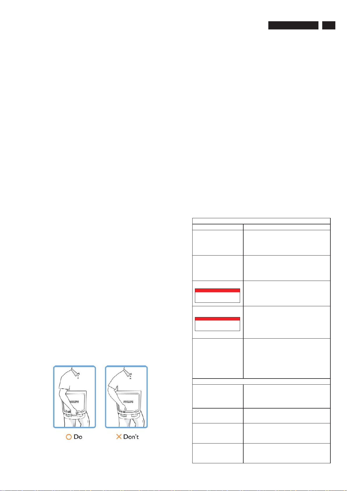
o. Warning for lifting monitor - Do not use the area underneath
the logo cover to grip or lift the monitor. Placing weight on the
logo cover can cause it to break away from the body and
cause the monitor to fall. When lifting the monitor, place one
hand under the monitor's frame.
http://www.wjel.net
Installation Locations
Avoid exposure to heat and extreme cold.
Do not store or use the LCD monitor in locations exposed to
heat, direct sunlight or extreme cold.
Avoid moving the LCD monitor between locations with large
temperature differences. Choose a site that falls within the
following temperature and humidity ranges.
Temperature: 0-35°C 32-95°F
Humidity: 20-80% RH
Do not subject the LCD monitor to severe vibration or high
impact conditions. Do not place the LCD monitor in the trunk of
a car.
Take care not to mishandle this product by either knocking or
dropping it during operation or transportation.
Do not store or use the LCD monitor in locations where there is
a high level of humidity or in dusty environments. Do not allow
water or other liquids to spill on or into the LCD monitor.
Trouble Shooting
This page deals with problems that can be corrected by the
user. If the problem still persists after you have tried these
solutions, contact your nearest Philips dealer.
Common Problems
Having this problem Check these items
No Picture
(Power LED not lit)
No Picture
(Power LED is amber or
yellow)
Screen says
ATTENTION
ENTERING SLEEPING MODE
Screen says
ATTENTION
CANNOT DISPLAY THIS VIDEO
MODE, CHANGE COMPUTER DISPLAY
INPUT TO 1680X1050 @60HZ
AUTO button not working
properly
a. Make sure the power cord is plugged into the power
outlet and into the back of the monitor.
b. First, ensure that the power button on the front of the
monitor is in the OFF position, then press it to the ON
position.
a. Make sure the computer is turned on.
b. Make sure the signal cable is properly connected to
your computer.
c. Check to see if the monitor cable has bent pins.
d.TheEnergySavingfeaturemaybeactivated.
a. Make sure the monitor cable is properly connected
to your computer.
(Also refer to the Quick Set-Up Guide).
b. Check to see if the monitor cable has bent pins.
c. Make sure the computer is turned on.
a. Make sure the vertical sync of input signal is within
the range of 56 ~ 75 Hz.
b. Change the refresh rate to 56~75Hz within
10 minutes.
c. Re-power on monitor to start over again if you failed
to change the refresh rate within 10 minutes.
a. The Auto Function is designed for use on standard
Macintosh or IBM-compatible PCs running Microsoft
Windows.
b. It may not work properly if using nonstandard PC or
video card.
c. The AUTO adjustment does not function when digital
input is used for display.
* Consult a service technician if the monitor does not operate
normally when the operating instructions given in this manual
have been followed.
Imaging Problems
Display position is incorrect
Image vibrates on the screen
Vertical flicker appears
Horizontal flicker appears
a. Press the Auto button.
b. Adjust the image position using the
Horizontal Position and/or Vertical Position
in OSD Main Controls.
a. Check that the signal cable is properly connected
to the graphics board or PC.
a. Press the Auto button.
b. Eliminate the vertical bars using the Phase/Clock
of More Settings in OSD Main Controls.
a. Press the Auto button.
b. Eliminate the vertical bars using the Phase/Clock
of More Settings in OSD Main Controls.
Page 10
10
The screen is too bright or
too dark
An after-image appears
An after-image remains after
the power has been turned off
220VW8 LCD
Definition of Pixel Defects
Adjust the contrast and brightness on
OSD Main Controls.
(The backlight of the LCD monitor has a fixed
life span. When the screen becomes dark or
begins to flicker,please contact your dealer).
If an image remains on the screen for an extended
period of time, it may be imprinted in the screen
and leave an after-image. This usually disappears
after a few hours.
This is characteristic of liquid crystal and is not
caused by a malfunction or deterioration of the
liquid crystal. The after-image will disappear after
a peroid of time.
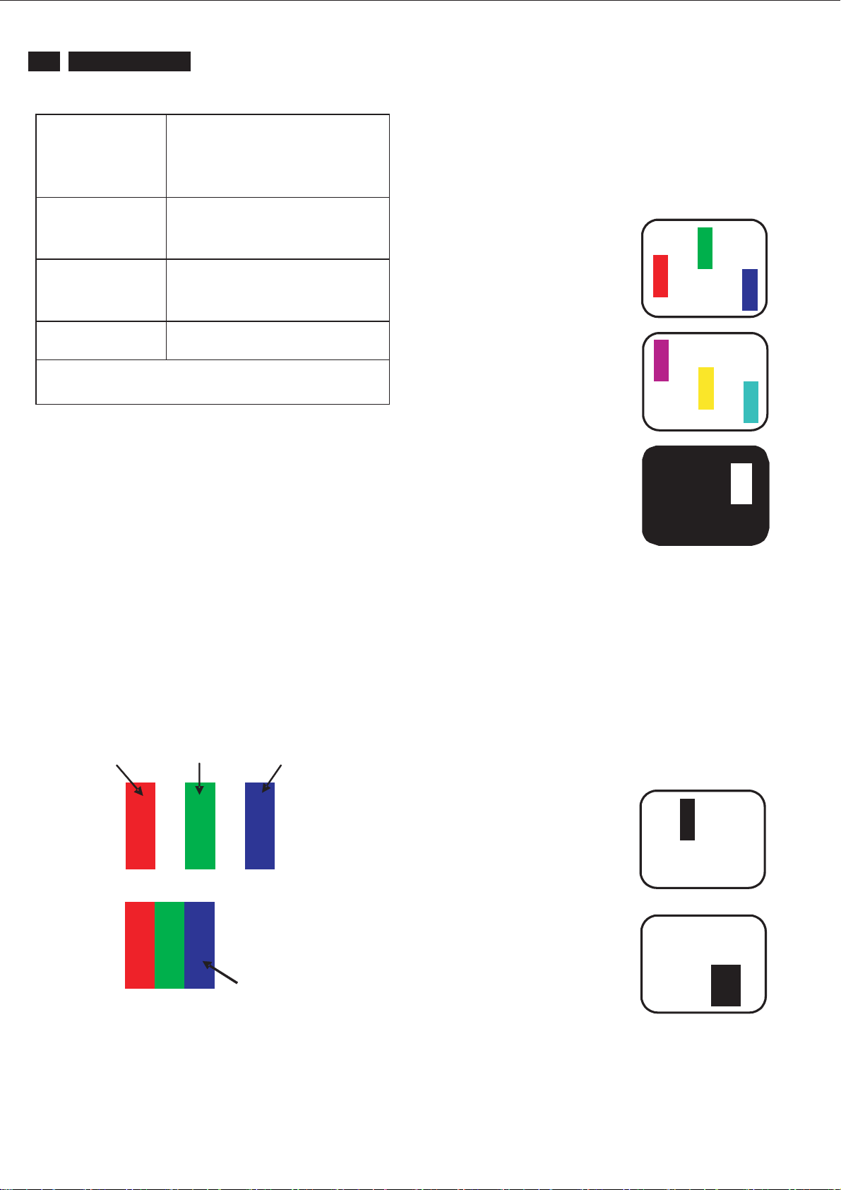
Bright Dot Defects
Bright dot defects appear as pixels or sub pixels that are
always lit or 'on'. That is, a bright dot is a sub-pixel that
stands out on the screen when the monitor displays a dark
pattern. There are the types of bright dot defects:
G
One lit red, green or blue sub pixel
R
B
Green, red, blue, dark, and
white dots remains
For further assistance, refer to the Consumer Information Centers list
and contact your local Philips distributor.
Definition of Pixel Defects
This section explains the different types of pixel defects and
defines acceptable defect levels of each type. In order to
quality for repair or replacement under warranty, the number
of pixel defects on a TFT LCD panel must exceed these
acceptable levels.
1. Definition of Pixels and Sub-pixels
A pixel, or picture element, is composed of three sub pixels
in the primary colors of red, green and blue. Many pixels
together form an image. When all sub pixels of a pixel are lit,
the three colored sub pixels together appear as a single
white pixel. When all are dark, the three colored sub pixels
together appear as a single black pixel. Other combinations
of lit and dark sub pixels appear as single pixels of other
colors.
The remaining dots are normal characteristic of
the liquid crystal used in today’s technology.
subpixel subpixel subpixel
Two adjacent lit sub pixels:
-Red+Blue=Purple
- Red + Green = Yellow
- Green + Blue = Cyan (Light Blue)
Three adjacent lit sub pixels
(one white pixel)
A red or blue bright dot must be more than 50
percent brighter than neighboring dots while a
green bright dot is 30 percent brighter than
neighboring dots.
Black Dot Defects
Black dot defects appear as pixels or sub pixels that are
always dark or 'off'. That is, a dark dot is a sub-pixel that
stands out on the screen when the monitor displays a light
pattern. These are the types of black dot defects:
P
Y
C
W
RGB
http://www.wjel.net
RGB
Pixel
2. Types of Pixel Defects
Pixel and sub pixel defects appear on the screen in different
ways. There are two categories of pixel defects and several
types of sub pixel defects within each category.
One dark sub pixel
Two or three adjacent
dark sub pixels
Page 11
Definition of pixel defects
3. Proximity of Pixel Defects
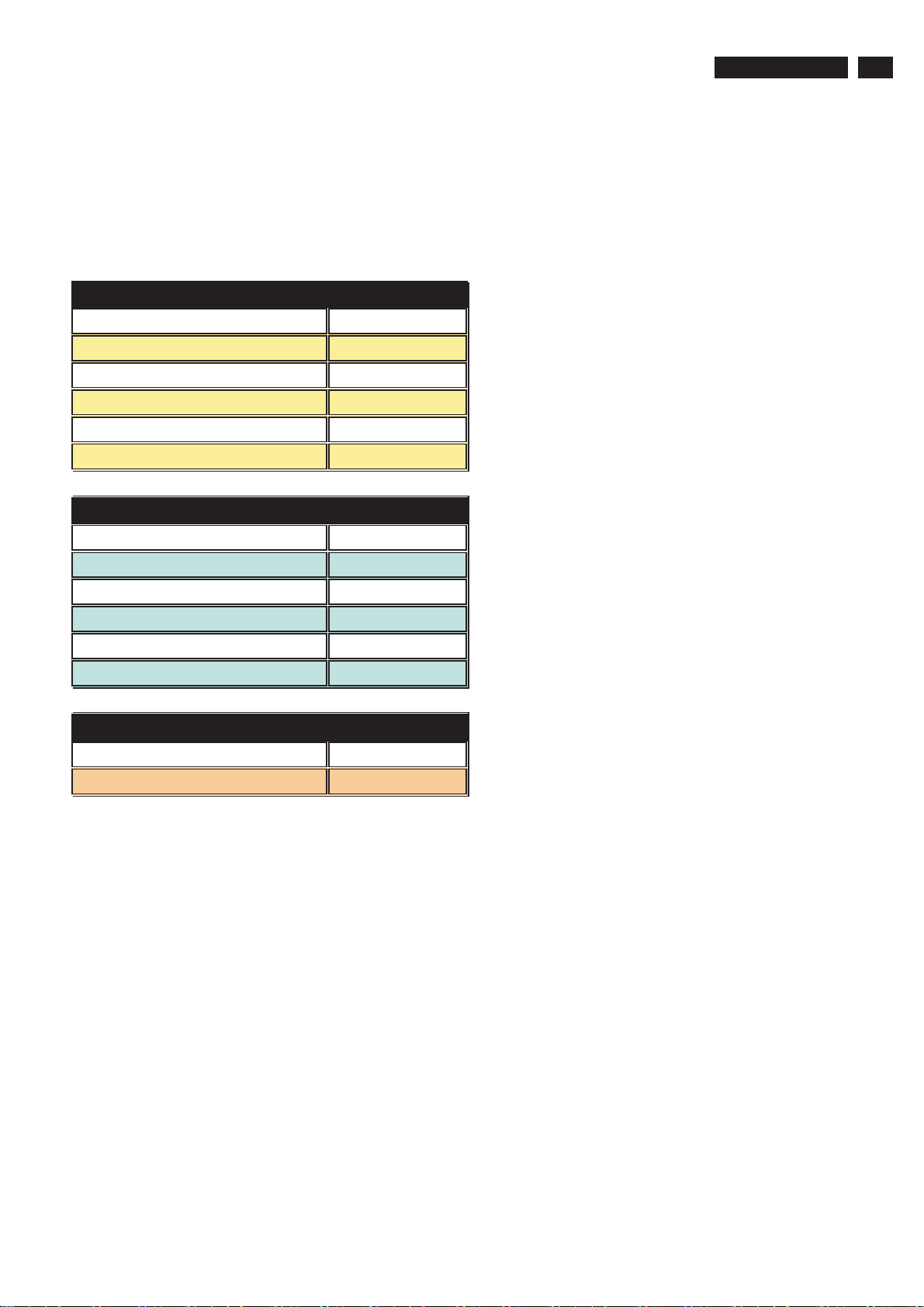
Because pixel and sub pixels defects of the same type that
are near to one another may be more noticeable, Philips also
specifies tolerances for the proximity of pixel defects.
Perfect Panel - ISO 13406-2 Class II compliant do-defectfree-display.
BRIGHT DOT DEFECTS ACCEPTABLE LEVEL
MODEL 220VW8
1 lit subpixel 3
2 adjacent lit subpixels 1
3 adjacent lit subpixels (one white pixel) 0
Distance between two bright dot defects* 15 mm
Total bright dot defects of all types 3
BLACK DOT DEFECTS ACCEPTABLE LEVEL
220VW8 LCD
11
MODEL 220VW8
1 dark subpixel 5
2 adjacent dark subpixels 2
3 adjacent dark subpixels 0
Distance between two black dot defects* 15 mm
Total black dot defects of all types 5
TOTAL DOT DEFECTS ACCEPTABLE LEVEL
MODEL 220VW8
Total bright or black dot defects of all types 5
Note:
* 1 or 2 adjacent sub pixel defects = 1 dot defect
http://www.wjel.net
Page 12
220VW8 LCD
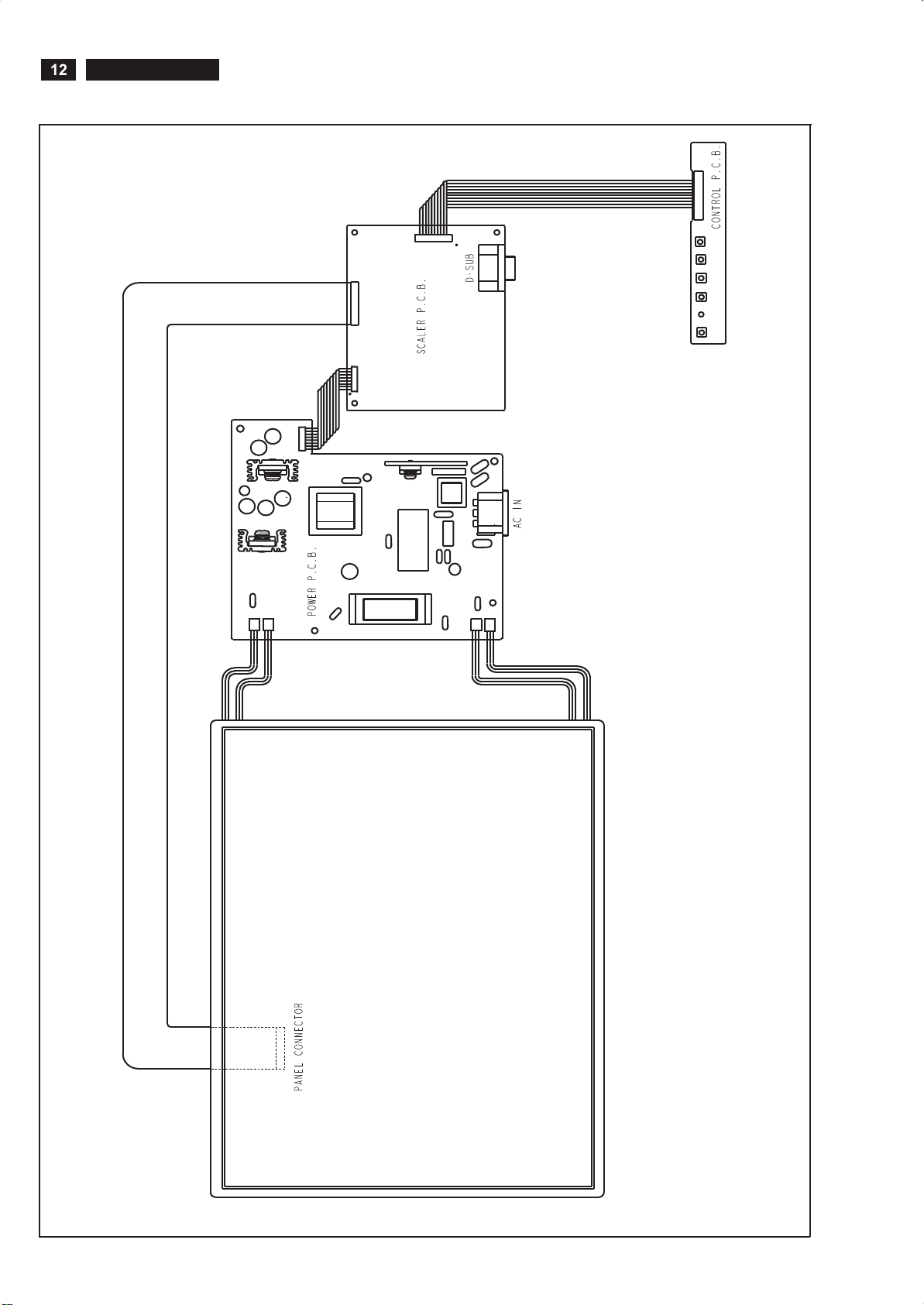
Wiring Diagram
8
1
CN78 1
29
30
CN2
1
2
7
8
CN1
1
2
CN101
CN1
CN2
CN3
CN3
CN4
CON1
http://www.wjel.net
Page 13
Mechnical instructions
220VW8 LCD
13
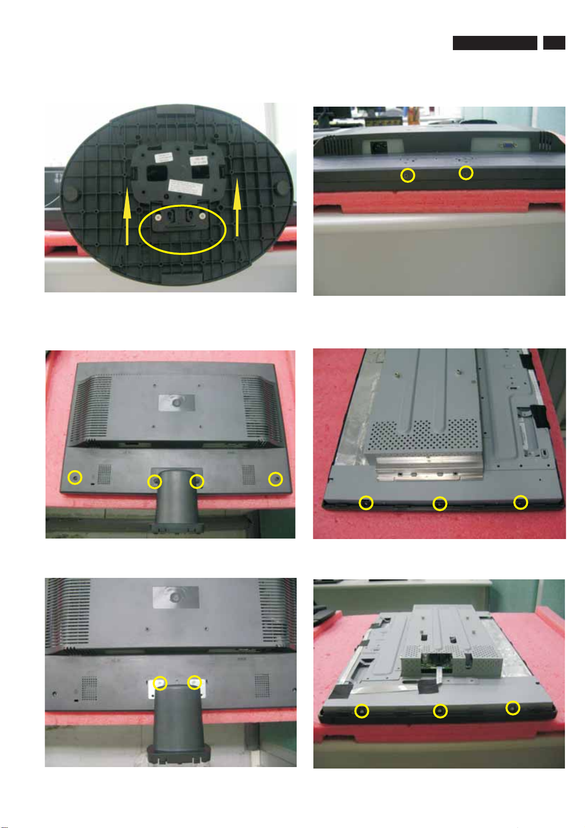
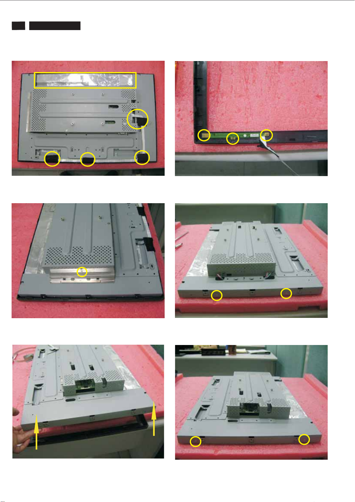
1. Put down the monitor softly and take out the base from
it.(note: care of the panel without scraped.)
Fig. 1
2. Release 2pcs screws from rear cover, and release 2pcs
screws from hinge cover too, then take off hinge cover.
4. Release 2pcs screws from bottom of rear cover, then take
off the rear cover.
Fig. 4
5. Release 3pcs screws from left side of bezel.
Fig. 2
3. Release 2pcs screws from stand and take off it stand.
http://www.wjel.net
Fig. 3
Fig. 5
6. Release 3pcs screws from right side of bezel.
Fig. 6
Page 14
14
220VW8 LCD
Mechnical instructions
7. Tear off all the tapes and AL FOIL, and disconnect the cable
between Main/B and Bottom/B.
Fig. 7
8. Release 1pcs screw from POWER/B shielding, and take off it.
10. Release 3pcs screws from Button/B, and take off it.
Fig. 10
11. Release 2pcs screws from left side of PCB shielding.
Fig. 8
9. Separate the bezel from panel.
Fig. 9
Fig. 11
12. Release 2pcs screws from right side of PCB shielding.
http://www.wjel.net
Fig. 12
Page 15
Mechnical instructions
220VW8 LCD
15
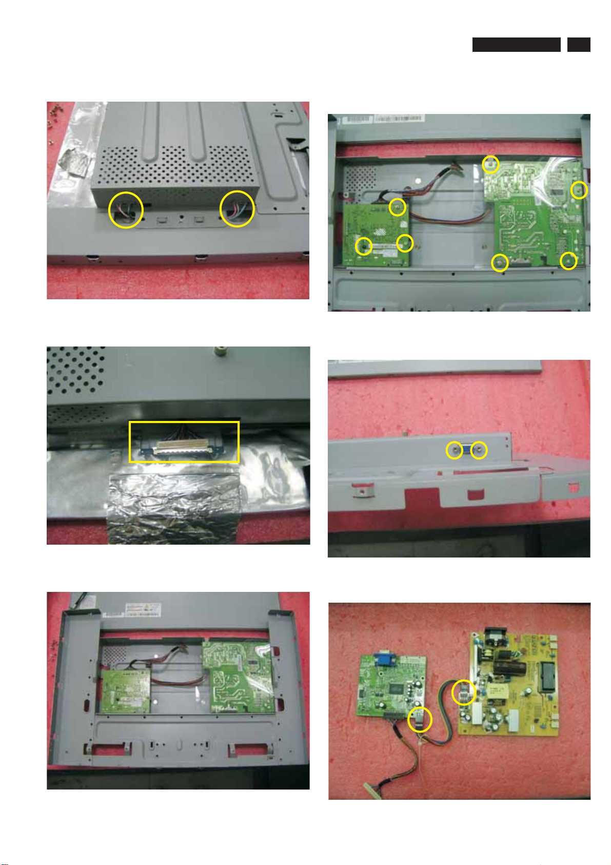
13. Disconnect the lamp cables from Power/B.
Fig. 13
14. Disconnect the LVDS cable from panel.
16. Release 7pcs screws from Main/B and Power/B and take
offthePowermylar.
Fig. 16
17.Release2pcsIONUTfromVGAjointofMain/B.
Fig. 14
15. Separate the PCB shielding from panel.
http://www.wjel.net
Fig. 15
Fig. 17
18. Disconnect the Main/B and Button/B.
Fig. 18
Page 16
16
F/W upload instruction
Configuration and procedure (ISP Tool)
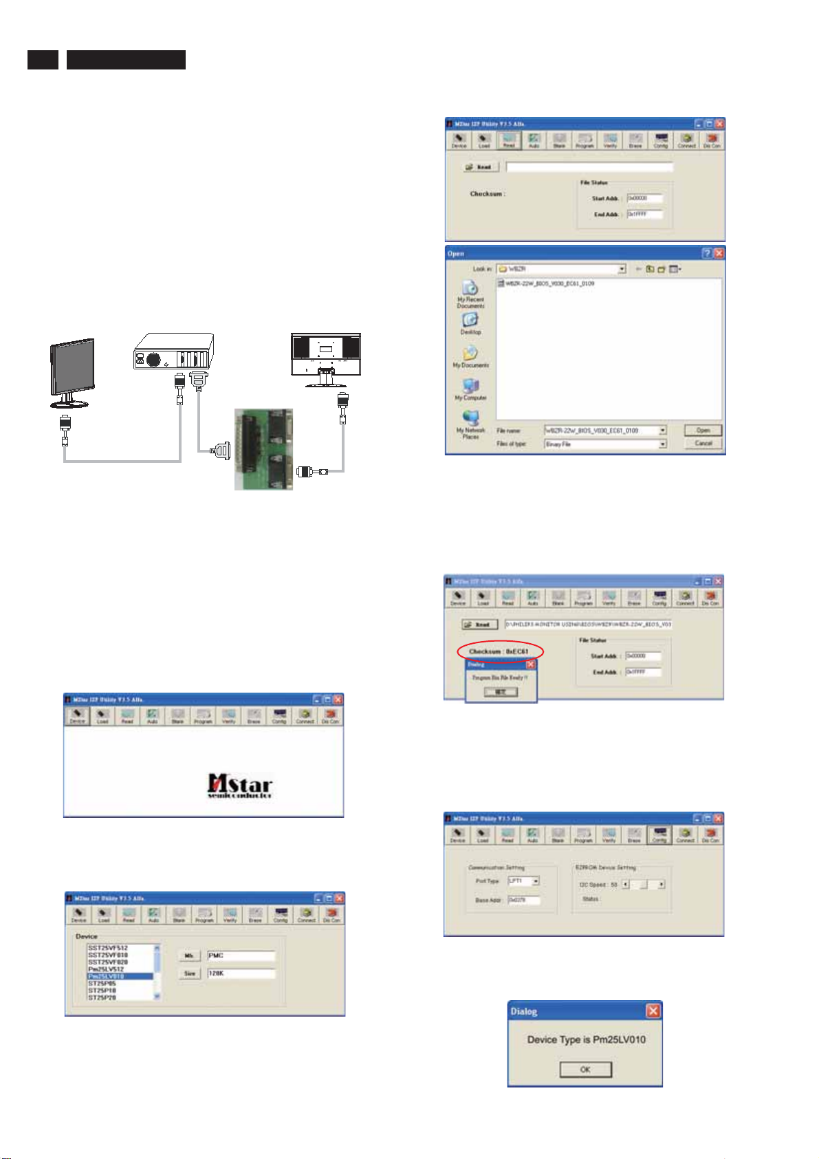
"ISP Tool " software is provided by Mstar to upgrade the
firmware of Scaler IC. It is a windows-based program, which
cannot be run in MS-DOS.
System and equipment requirements:
1. An i486 (or above) personal computer or compatible.
2. Microsoft operation system Windows 98/2000/XP.
3. ISP software " ISP Tool ".
(No need to install, it can be performed directly)
4. Firmware uploading tool, as shown in Fig1.
220VW8 LCD
Electrical Instructions
Monitor(A)
* Connect the firmware uploading tool as Fig.1 shown.
* Before the servicer perform the ISP Toll program, the
Communicating connection must be well done.
* When the connection fixed, power on the monitor.
Setup and perform the ISP Tool program
1. Save the software in your PC, and create a shortcut
on the desktop.
2. Double click the ISP Tool. exe icon at the desktop then
appears window as shown in Fig. 2.
PC
To LPT1 port
ISP TOOL
To graphics card
Fig. 1
Monitor (B)
To monitor
Fig. 4
5. If the hex file opened correctly, a message will be showed in
the dialog box to notice the operator. At this moment, please
verify the checksum of the hex file with the firmware control
table to make sure the suitable file will be used. Mentioned
firmware control table will be provided by supplier(Fig.5)
Fig. 5
Fig. 2
http://www.wjel.net
3. Press the device icon then select the matching IC type and
double click it as shown in Fig. 3.
Fig. 3
4. Press the read icon, file status will shown the start address
as 0X00000 and end address as 0X1FFFF. Then open the
destination hex files as shown in Fig.4.
6. Press the config icon to setting up:
Port type : LPT1
Base Addr : 0X0378
E2PROM device setting : 50 (default value)
7. Press connect icon to create a linkage between PC and
monitor. If the linkage was steady, a dialog box will shown
as Fig. 6. At this moment, LED of monitor will be black out.
Page 17
Electronic Instruction
220VW8 LCD
17
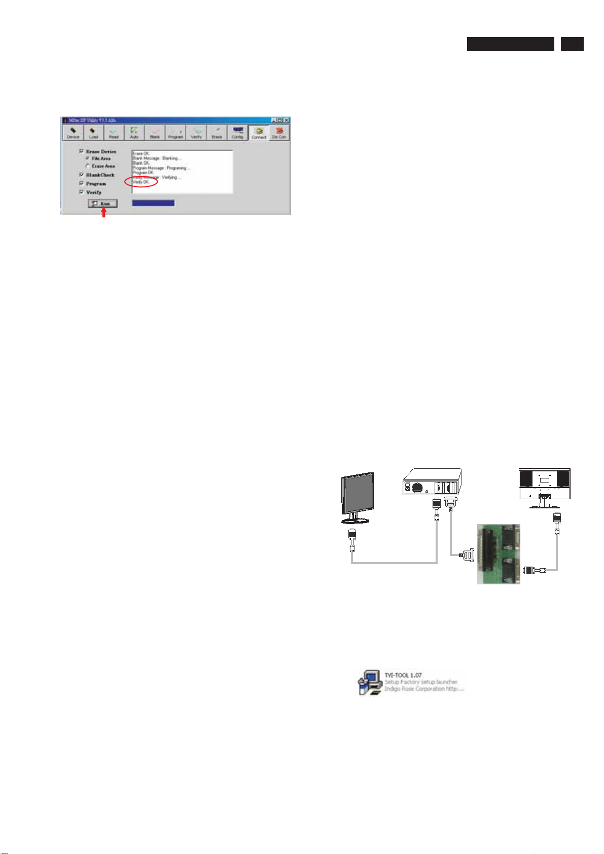
7. Press icon of the toolbox and make sure all of the
8. When the loading process completed, and the dialog box
AUTO
setting are fixed, then press the icon. Program will
perform the loading process automatically.
appeared the message of verify ok. Press the icon
to disconnect the linkage, LED of monitor will light up.
RUN
DIS-CON
DDC instructions
General
DDC Data Re-programming
In case the DDC data memory IC or main EEPROM which
storage all factory settings were replaced due to a defect, the
serial numbers have to be re-programmed.
It is advised to re-soldered DDC IC and main EEPROM from
the old board onto the new board if circuit board have been
replaced, in this case the DDC data does not need to be reprogrammed.
* According to the design concept of this product, DDC data
will be divided into two parts to deposit in different place:
DDC data of VGA interface are saved in scaler IC.
Additional information
Additional information about DDC (Display Data Channel) may
be obtained from Video Electronics Standards Association
(VESA). Extended Display Identification Data(EDID)
information may be also obtained from VESA.
System and equipment requirements
1. An i486 (or above) personal computer or compatible.
2. Microsoft operation system Windows 98/2000/XP.
3. Installation software of " TVI Tool ".
4. Executive program " TVI Tool. exe ".
5. ISP tool kit, as shown in Fig1.
Including: a. Alignment fixture x 1
b. Printer cable (LPT type) x 1
c. D-sub to D-sub cable x 1
Monitor(A)
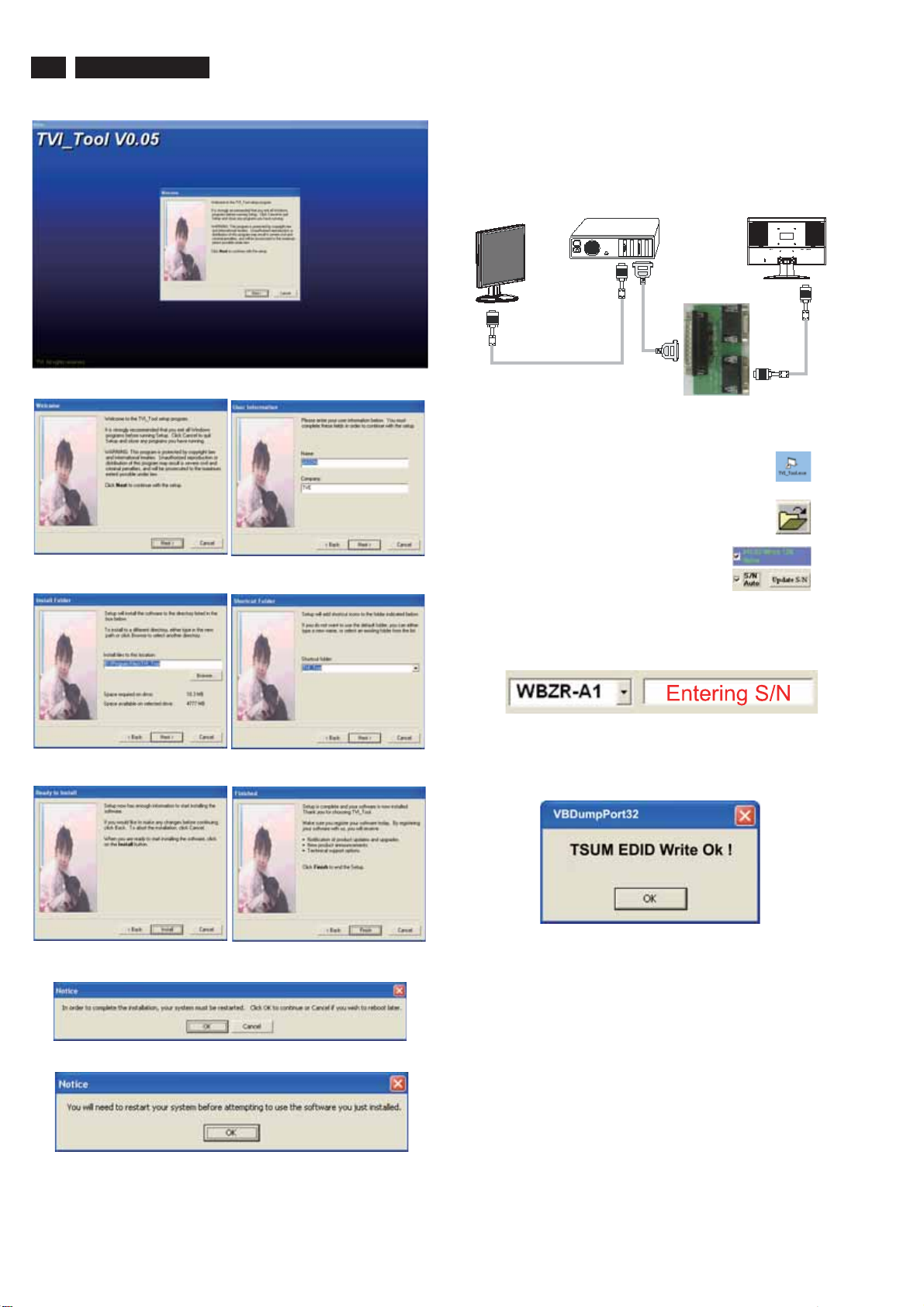
Install and setup programTVI-TOOL
http://www.wjel.net
Step 1: Create a folder in your PC, for example : D:\TVI-TOOL.
Step 2: Copy the installation file into the folder.
Step 3: Double click the INSTALL icon as shown in the Fig.2.
Step 4: Following the installation wizard, complete the whole
installing progress.
Step 5: Restart your PC to
(More details are shown in the next page)
PC
To LPT1 port
ISP TOOL
To graphics card
Fig. 1
Monitor (B)
To monitor
Page 18
18
220VW8 LCD
Electronic Instruction
Re-programming Analog DDC
Step 1: After initialize the alignment fixture, connecting all
cables as shown in Fig.10.
Fig.1 (Installation interface)
Fig.2 Fig.3
Monitor(A)
Step 2: Connect the power code of monitor and power on it.
Step 3: Double check the icon
to run the TV_TOOL.exe.
Step 4: Click the icon at the main menu
to open the DDC files.
Step 5: Select the icon of DDC IC type and
serial number write-in method.
Step 6: Entering the monitor’s serial number into the block
as shown in following photos, program will running
Automatically.
OPEN
PC
To LPT1 port
ISP TOOL
To graphics card
Fig. 10
TVI_TOOL
Monitor (B)
To monitor
Fig.4 5
Fig.6 7
http://www.wjel.net
Fig.8
Fig.9
Fig.
Fig.
Step 7: When the DDC data download into the DDC IC, a
dialog box will be appeared automatically as shown
in below photos.
Step 8: Press the OK button, waiting for several seconds
and then power off the monitor.
Page 19
Electronic Instruction
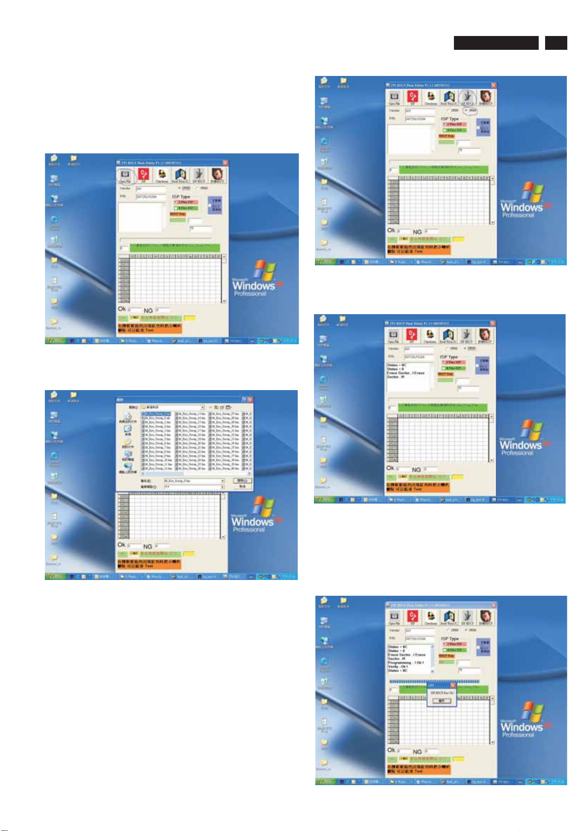
Re-programming of writing HDCP KEY
Step 1: Please install the software of isp HDCP key Version1.13
,the tool is the same with isping EDID.
Step 2: Opening the software.
Step 3: Pressing the button of “OPEN FILE”, as follows:
220VW8 LCD
Step 6: The software will write HDCP KEY into monitor.
19
Step 4: Choosing the HDCP KEY that you save:
http://www.wjel.net
Step 5: If the Flash Rom of monitor is 2MB, please
choose”3F000”,but if it is 1MB please choose 1F000(if you
choose amiss ,the monitor maybe shut down) ,then press
button of ”ISP HDCP”.
the
Step 7: If the software write HDCP KEY into monitor
successfully ,the message will be display ,as follow , if the
software write HDCP KEY into monitor unsuccessfully
,please check the cable ,and restart from step5 .
Page 20

20
220VW8 LCD
DDC data
DDC DATA
THE DISPLAY DATA CHANNEL (DDC_2B) CONTENT INCLUDING:
(Analog mode)
------------------------------------------------------------------------------------128 BYTES OF EDID CODE :
0 12 34 5678 9
-----------------------------------------------------------------------
0|00FFFFFFFFFFFF00410C
10|530801 0101 010811 0103
20|082F1E782E 9345A3554A
30|98271550 54BFEF00B300
40|A940950F 950081C08140
50|714F8180 21399030621A
60|274068B03600DA281100
70|001C000000FF00434A31
80|30373038 313233343536
90|000000FC005068696C69
100|70732032 323056570000
110 | 00 FD 00 38 4C 1E 5D 11 70 0A
120|20323230 57530014
__________________________________________________
(08-09) ID Manufacturer Name = PHL
(10-11) Product ID Code (Non-Alphanumerical) = 0853 - (2131)
(12-15) Last 5 Digits of Serial Number = NOT SPECIFIED
(16) Week of Manufacture = 08
(17) Year of Manufacture = 2007
(10-17) Complete Serial Number = NOT SPECIFIED
(18) EDID Structure Version Number = 1
(19) EDID Structure Revision Number = 3
(20) VIDEO INPUT DEFINITION : = Separate Sync,
Analog signal, 0.700V/0.300V (1.000 Vp-p)
(38-53) Standard Timing Identification:
#1: 1680 x 1050 @ 60Hz
#2: 1600 x 1200 @ 60Hz
#3: 1440 x 900 @ 75Hz
#4: 1440 x 900 @ 60Hz
#5: 1280 x 720 @ 60Hz
#6: 1280 x 960 @ 60Hz
#7: 1152 x 864 @ 75Hz
#8: 1280 x 1024 @ 60Hz
(54-71) Detail Timing Description #1:
1680x1050 Pixel Clock=146.2MHz
-------------------------------------------------------------------------------Horizontal Image Size=474mm
Vertical Image Size=296mm
Refresh Mode:
Non-Interlaced Normal display, no stereo
HORIZONTAL:
Active Time = 1680 pixels
Blanking Time = 560 pixels
Sync Offset = 104 pixels
Sync Pulse Width = 176 pixels
Border = 0 pixels
Frequency = 65.3 kHz
VERTICAL:
Active Time = 1050 lines
Blanking Time = 39 lines
Sync Offset = 3 lines
Sync Pulse Width = 6 lines
Border = 0 lines
Frequency = 60.0 Hz
(21) Maximum Horizontal Image Size = 470mm
(22) Maximum Vertical Image Size = 300mm
(23) Display Gamma = 2.20
(24) DPMS Supported Feature: = Active Off.
Display type = RGB color display
(25-34) CHROMA INFO:
Red x = 0.639 Green x = 0.289
Blue x = 0.153 White x = 0.313
Red y = 0.333 Green y = 0.597
Blue y = 0.082 White y = 0.329
(35) ESTABLISHED TIMING I:
720 x 400 @ 70Hz (VGA, IBM)
640 x 480 @ 60Hz (VESA)
640 x 480 @ 67Hz (MAC II, Apple)
640 x 480 @ 72Hz (VESA)
640 x 480 @ 75Hz (VESA)
800 x 600 @ 56Hz (VESA)
800 x 600 @ 60Hz (VESA)
(36) ESTABLISHED TIMING II:
800 x 600 @ 72Hz (VESA)
800 x 600 @ 75Hz (VESA)
832 x 624 @ 75Hz (MAC II, Apple)
1024 x 768 @ 60Hz (VESA)
1024 x 768 @ 70Hz (VESA)
1024 x 768 @ 75Hz (VESA)
1280 x 1024 @ 75Hz (VESA)
http://www.wjel.net
Sync configuration: Digital separate, V(+), H(-)
(72-89) Monitor Description:
-------------------------------------------------------------------------------Monitor S/N: CJ10708123456
(90-107) Monitor Description:
--------------------------------------------------------------------------------
Monitor Name: Philips 220VW
(108-125) Monitor Description:
--------------------------------------------------------------------------------
Monitor Range Limits:
Vertical Frequency (min) = 56Hz
Vertical Frequency (max) = 76Hz
Horizontal Frequency (min) = 30KHz
Horizontal Frequency (max) = 93KHz
Maximum Supported Pixel Clock = 170MHz
(127) Checksum OK.
(37) Manufacturer's Reserved Timing:
None specified.
Page 21
Safety Instruction, Warnings and Notes
220VW8 LCD
21
Safety instruction, warnings and notes
index of this chapter:
1 Safety Instructions
2 Warnings
3 Notes
1 Safety Instructions
Safety regulations require that during a repair:
a. Connect the set to the AC Power via an isolation transformer
(> 800 VA).
b. Replace safety components, indicated by the symbol ,
only by components identical to the original ones. Any other
component substitution (other than original type) may
increase risk of fire or electrical shock hazard.
Safety regulations require that after a repair, the set must be
returned in its original condition. Pay in particular attention to
the following points:
a. Route the wire trees correctly and fix them with the mounted
cable clamps.
b. Check the insulation of the AC Power lead for external
damage.
c. Check the strain relief of the AC Power cord for proper
function.
d. Check the electrical DC resistance between the AC Power
plug and the secondary side (only for sets which have a AC
Power isolated power supply):
* Unplug the AC Power cord and connect a wire between the
two pins of the AC Power plug.
* Set the AC Power switch to the "on" position (keep the AC
Power cord unplugged!).
* Measure the resistance value between the pins of the AC
Power plug and the metal shielding of the tuner or the aerial
connection on the set. The reading should be between 4.5
Mohm and 12 Mohm.
* Switch "off" the set, and remove the wire between the two
Pins of the AC Power plug.
e. Check the cabinet for defects, to avoid touching of any inner
parts by the customer.
3.2 Schematic Notes
All resistor values are in ohms and the value multiplier is often
used to indicate the decimal point location (e.g. 2K2 indicates
2.2 Kohm).
Resistor values with no multiplier may be indicated with either
an "E" or an "R" (e.g. 220E or 220R indicates 220 ohm).
All capacitor values are given in micro-farads ( X10 ),
nano-farads (n= X10 ), or pico-farads (p= X10 ).
Capacitor values may also use the value multiplier as the
decimal point indication (e.g. 2p2 indicates 2.2 pF).
An "asterisk" (*) indicates component usage varies. Refer to the
diversity tables for the correct values.
The correct component values are listed in the Electrical
Replacement Parts List. Therefore, always check this list when
there is any doubt.
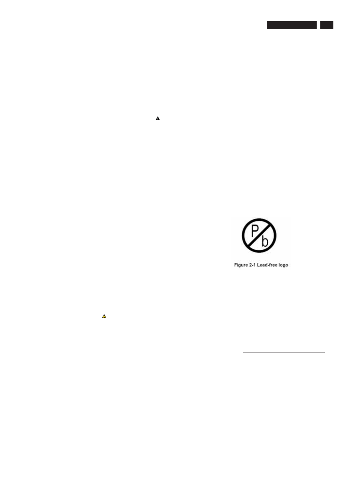
3.3 Lead Free Solder
Philips CE is going to produce lead-free sets (PBF) from
1.1.2005 onwards.
Lead-free sets will be indicated by the PHILIPS-lead-free logo
on the Printed Wiring Boards (PWB):
This sign normally has a diameter of 6 mm, but if there is less
space on a board also 3 mm is possible.
-9 -12
-6
2 Warnings
a. All ICs and many other semiconductors are susceptible to
electrostatic discharges (ESD ). Careless handling during
repair can reduce life drastically. Make sure that, during
repair,
you are connected with the same potential as the mass of the
set by a wristband with resistance. Keep components and
tools also at this same potential.
b. Be careful during measurements in the high voltage section.
c. Never replace modules or other components while the unit
is switched "on".
d. When you align the set, use plastic rather than metal tools.
This will prevent any short circuits and the danger of a circuit
becoming unstable.
3 Notes
3.1 General
Measure the voltages and waveforms with regard to the
chassis ground or hot ground, depending on the tested area of
circuitry. The voltages and waveforms shown in the diagrams
are indicative.
The semiconductors indicated in the circuit diagram and in the
parts lists, are interchangeable per position with the
semiconductors in the unit, irrespective of the type indication on
http://www.wjel.net
In case of doubt wether the board is lead-free or not (or with
mixed technologies), you can use the following method:
* Always use the highest temperature to solder, when using
SAC305 (see also instructions below).
* De-solder thoroughly (clean solder joints to avoid mix of
two alloys).
Caution
profile, which is coupled to the 12NC. For an overview of these
profiles, visit the website
You will find this and more technical information within the
"Magazine", chapter "Workshop information".
For additional questions please contact your local repair desk.
Due to lead-free technology some rules have to be respected
by the workshop during a repair:
Use only lead-free soldering tin Philips SAC305 with order code
0622 149 00106. If lead-free solder paste is required, please
contact the manufacturer of your soldering equipment.
In general, use of solder paste within workshops should be
avoided because paste is not easy to store and to handle.
Use only adequate solder tools applicable for lead-free
soldering tin. The solder tool must be able
- To reach at least a solder-tip temperature of 400 degree C.
- To stabilise the adjusted temperature at the solder-tip.
- To exchange solder-tips for different applications.
: For BGA-ICs, you must use the correct temperature
http://www.atyourservice.ce.philips.com/
Page 22
22
220VW8 LCD
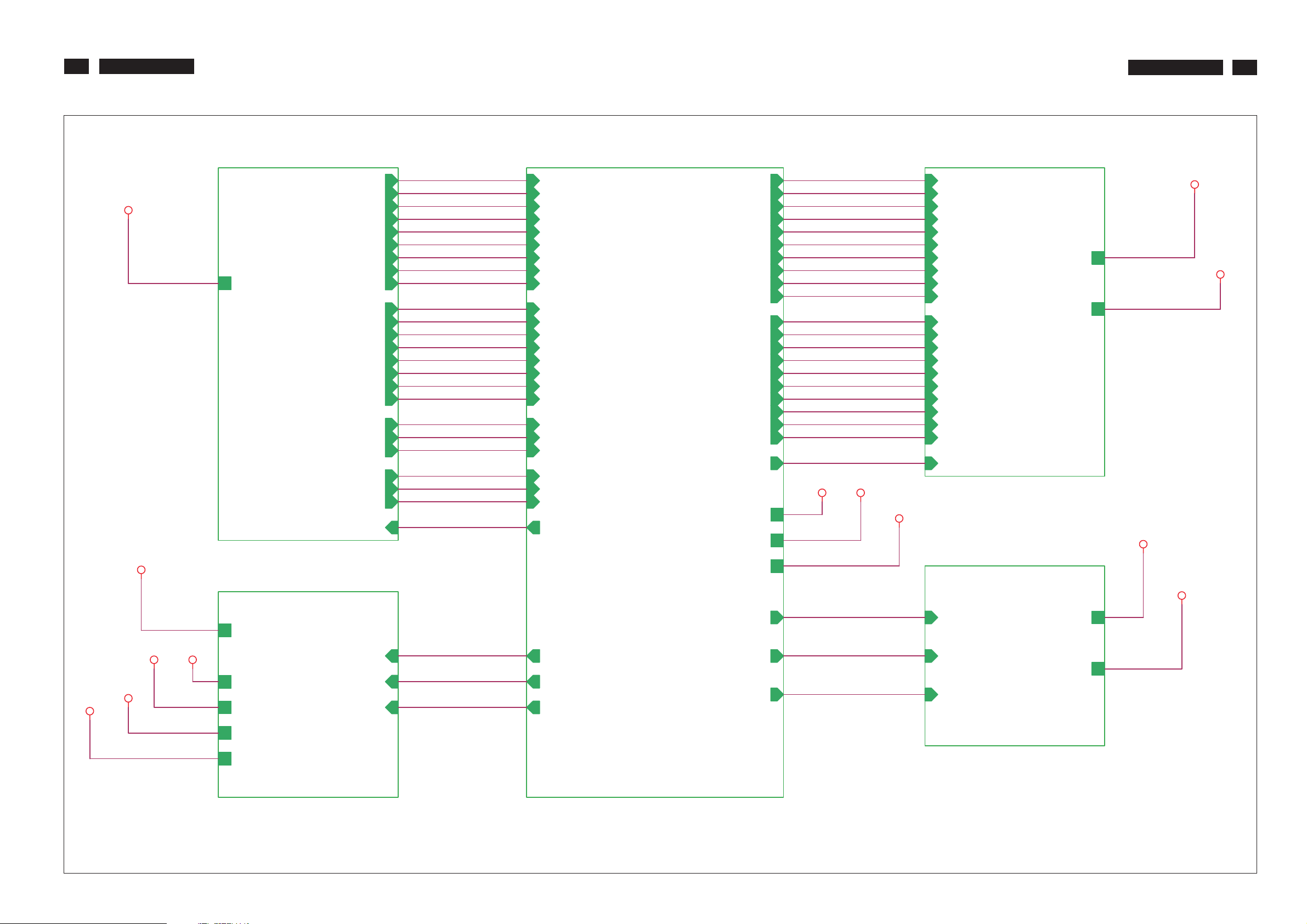
Block Diagram
220VW8 LCD
22
PC5V
PC5V
A3
PC5V
3.INPUT
A2
RIN
GNDR
GIN
GNDG
BIN
GNDB
SOG
VSYNC
HSYNC
R+
R-
G+
GB+
CLK+
CLK-
DDCA_SDA
DDCA_SCL
DET_VGA
DDCD_SDA
DDCD_SCL
DET_DVI
HPD_CTRL
B-
A4
RIN
GNDR
GIN
GNDG
BIN
GNDB
SOG
VSYNC
HSYNC
R+
R-
G+
G-
B+
BCLK+
CLK-
DDCA_SDA
DDCA_SCL
DET_VGA
DDCD_SDA
DDCD_SCL
DET_DVI
HPD_CTRL
LVA0P
LVA0M
LVA1P
LVA1M
LVA2P
LVA2M
LVACKP
LVACKM
LVA3P
LVA3M
LVB0P
LVB0M
LVB1P
LVB1M
LVB2P
LBA2M
LVBCKP
LVBCKM
LVB3P
LVB3M
on_PANEL
+5V
VCC1.8
VCC3.3
+5V VCC1.8
VCC3.3
A5
LVA0P
LVA0M
LVA1P
LVA1M
LVA2P
LVA2M
LVACKP
LVACKM
LVA3P
LVA3M
LVB0P
L VB0 M
LVB1P
L VB1 M
LVB2P
L VB2 M
LVBCKP
LVBCKM
LVB3P
LVB3M
on_PANEL
5.PANEL
A6
+5V
VCC12
VCC3.3
S-A3
+5V
VCC12
VCC12
VCC1.8
VCC3.3
VOLUME
PC5V
VCC12+5V
VCTRL
VCTRL
STBY
http://www.wjel.net
VCC12
+5V
VCC3.3
VCC1.8
2.POWER
on_BACKLIGHT
Adj_BACKLIGHT
on_BACKLIGHT
MUTE
Adj_BACKLIGHT
4.SCALER
VOLUME
STBY
MUTE
6.AUDIO
VCC3.3
VCC12
Page 23
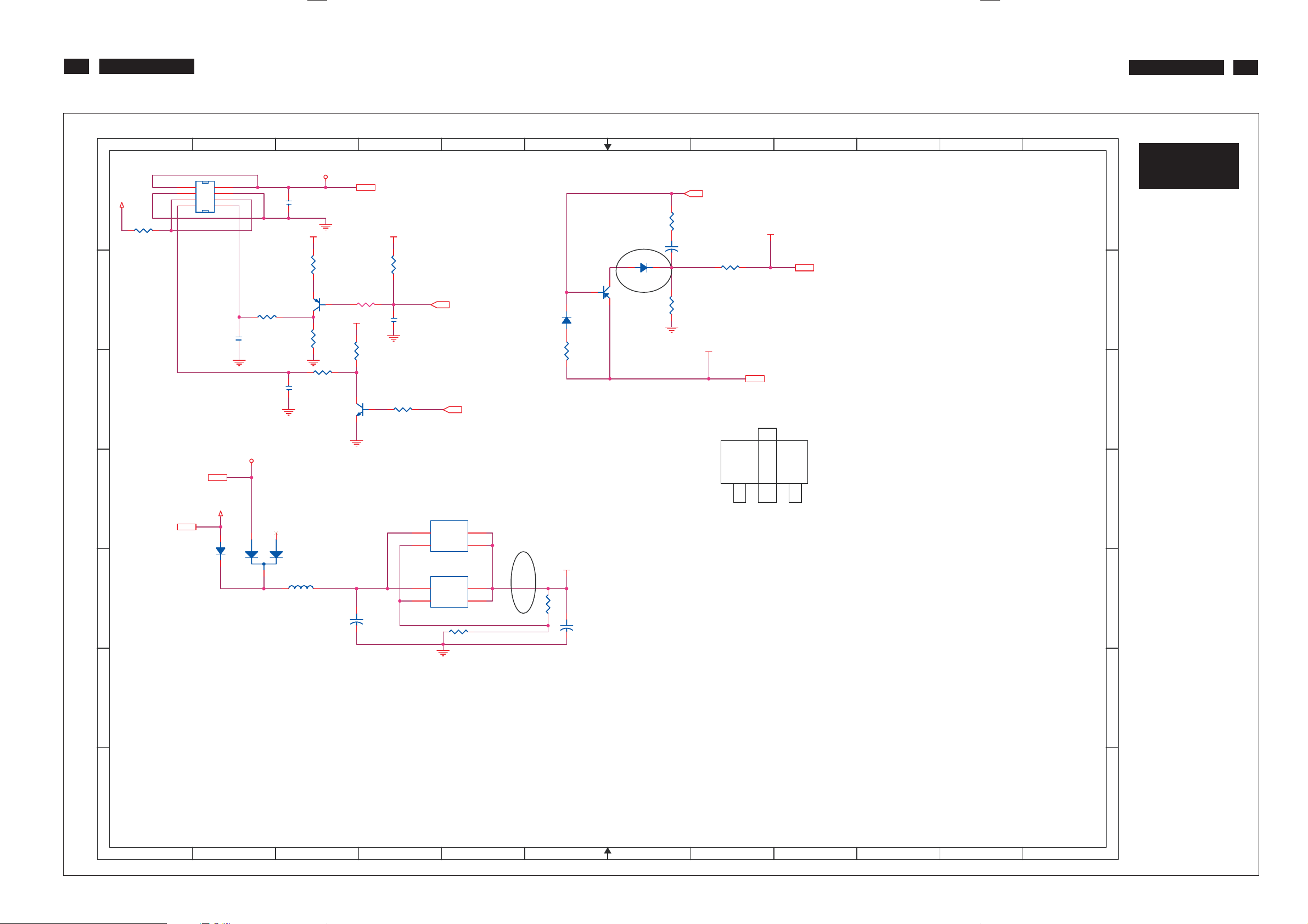
23
220VW8 LCD
Schematic Diagram(Scaler Board - Power)
220VW8 LCD
23
2
4
8
2
R5 10K/6R5 10K/6
C4
1uF/8C41uF/8
1
CN1 CONN 4x2-RCN1 CONN 4x2-R
1
3
+5V
A A
R1
0/1206R10/1206
5 6
7
B
C C
PC5V
PC5V3
D
3,4,5
+5V
+5V
D4
D4
SSM12LL
SSM12LL
L1
L1
E E
3
VCC12
C1
0.1uF/6C10.1uF/6
VCC3.3 VCC3.3
R2
0/6R20/6
Q1
Q1
R4 1K/6R4 1K/6
MMST3906
MMST3906
VCC3.3
R6
10K/6R610K/6
R9 0/6R9 0/6
C6
C6
1uF/8/NC
1uF/8/NC
D3
D3
BAT54C-GS08
BAT54C-GS08
CX201209813/8
CX201209813/8
31
+
+
R8
1K/6R81K/6
2N3904Q22N3904
330u/16V
330u/16V
C7
C7
Q2
2
VCC12 5,6
4
R3
10K/6R310K/6
C3
C3
0.1uF/6/NC
0.1uF/6/NC
R11 2.2K/6R11 2.2K/6
on_BACKLIGHT 4
U3-A1
U3-A1
3
VOUT
VIN
1
ADJ/GND
LT1117/TO252/NC
LT1117/TO252/NC
U1
U1
3
VOUT
VIN
1
ADJ/GND
LT1084/TO263
LT1084/TO263
330/6 1%
330/6 1%
5
Adj_BACKLIGHT 4
2
4
OUT
2
4
OUT
R18
R18
R17
R17
200/6 1%
200/6 1%
6
VCC3.3
+
+
D2
1N4148D21N4148
R13
R13
100/6
100/6
C8
C8
330u/16V
330u/16V
ECB
9
VCC1.8 4
10
11
12
7
R7
47/6R747/6
C5
C5
+
+
4.7uF/16V
D1
D1
SSM12LL
SSM12LL
C
B
Q3
Q3
2SB1132PT
2SB1132PT
E
4.7uF/16V
R12
R12
2K/6
2K/6
8
VCTRL 4
VCC1.8
R10 0/6R10 0/6
VCC3.3
VCC3.3 4,6
D1 SOT-89
B
D
S-A3
S-A2
CN1 A2
C1 A3
C3 B4
C4 B2
C5 A7
C6 C3
C7 E3
C8 E6
D1 B7
D2 B6
D3 D2
D4 D2
L1 E3
Q1 B3
Q2 C3
Q3 B6
R1 A1
R2 B3
R3 B4
R4 B3
R5 B2
R6 B3
R7 A7
R8 B3
R9 C3
R10 B8
R11 C4
R12 B7
R13 B6
R17 E6
R18 E4
U1 E4
U3-A1 D4
http://www.wjel.net
F F
G G
1
2
3
4
5
6
7
8
9
10
11
12
Page 24
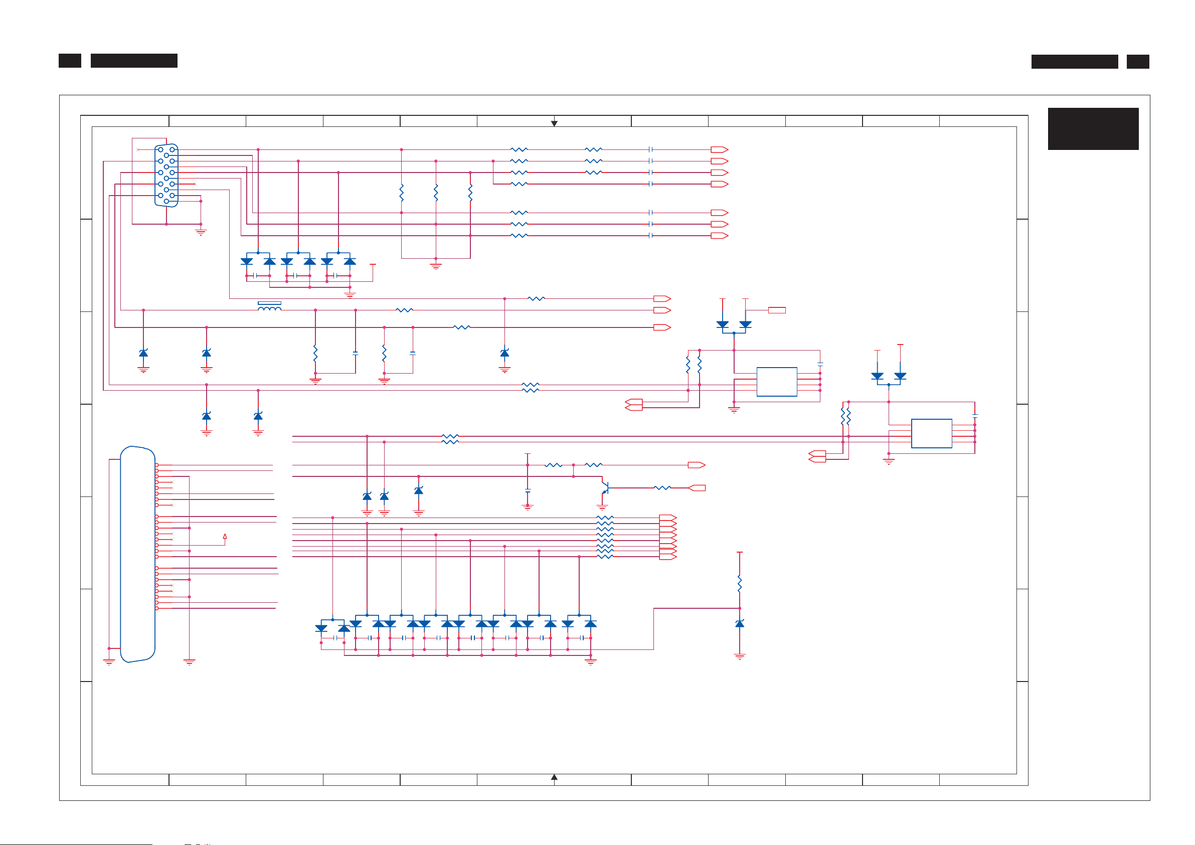
24
220VW8 LCD
Schematic Diagram(Scaler Board - Input)
220VW8 LCD
24
1
CN3
CN3
1617
11
12
VGA
VGA
13
14
15
A A
B
HSI
VSI
D9
CN4
CN4
RX2-
RX2+
GND
RX4-
RX4+
SCL
SDA
RX1-
RX1+
GND
RX3-
RX3+
GND
RX0-
RX0+
GND
RX5-
RX5+
GND
RXC+
RXC-
Z5.6V/NCD9Z5.6V/NC
1
2
3
4
5
6
7
8
VS
9
10
11
12
13
14
5V
15
16
HP
17
18
19
20
21
22
23
24
C C
D
25
E E
2
1
6
2
7
3
8
4
9
5
10
DVI5V
PC5V
D10
D10
D13
D13
Z5.6V/NC
Z5.6V/NC
Z5.6V/NC
Z5.6V/NC
DVI5V
C20 0.1uF/6/NCC20 0.1uF/6/NC
1
FB1 0/6FB1 0/6
DVI_SCL
DVI_SDA
F F
26
DVI-D/NC
DVI-D/NC
3
D5
D5
BAV99/NC
BAV99/NC
D14
D14
Z5.6V/NC
Z5.6V/NC
DAT2DAT2+
DAT1DAT1+
HPD
DAT0DAT0+
DCLK+
DCLK-
R
2
3
3
D6
D6
BAV99/NC
BAV99/NC
C21 0.1uF/6/NCC21 0.1uF/6/NC
1
G
C22 0.1uF/6/NCC22 0.1uF/6/NC
2
1
2.2K/6
2.2K/6
R44
R44
DVI_SCL
DVI_SDA
DVI5V
HPD
DAT0+
DAT0DAT1+
DAT1DAT2+
DAT2-
DCLK+
DCLK-
3
C28
C28
1
0.1uF/6/NC
0.1uF/6/NC
3
D7
D7
BAV99/NC
BAV99/NC
2
DAT_DDC
D18
D18
BAV99/NC
BAV99/NC
2
4
B
33pF/6
33pF/6
C23
C23
1
0.1uF/6/NC
0.1uF/6/NC
75/6 1%
75/6 1%
ESD_5V
Z5.6V/NC
Z5.6V/NC
D16
D16
3
D19
D19
BAV99/NC
BAV99/NC
C29
C29
2
R34
R34
R42 1K/6R42 1K/6
2.2K/6
2.2K/6
R45
R45
CLK_DDC
D17
D17
Z5.6V/NC
Z5.6V/NC
3
D20
D20
BAV99/NC
BAV99/NC
C30
C30
2
1
0.1uF/6/NC
0.1uF/6/NC
5
75/6 1%
75/6 1%
R35
R35
R43 1K/6R43 1K/6
33pF/6
33pF/6
C24
C24
R52 100/6/NCR52 100/6/NC
R53 100/6/NCR53 100/6/NC
D15
D15
Z5.6V/NC
Z5.6V/NC
3
D21
D21
BAV99/NC
BAV99/NC
C31
C31
2
1
0.1uF/6/NC
0.1uF/6/NC
6
R27 56/6 1%R27 56/6 1%
R29 56/6 1%R29 56/6 1%
R31 56/6 1%R31 56/6 1%
R33 470/6R33 470/6
R36
R36
75/6 1%
75/6 1%
R37 100/6 1%R37 100/6 1%
R38 100/6 1%R38 100/6 1%
R39 100/6 1%R39 100/6 1%
R41 100/6/NCR41 100/6/NC
D11
D11
Z5.6V/NC
Z5.6V/NC
R48 100/6R48 100/6
R49 100/6R49 100/6
DVI5V
R54 10K/6/NCR54 10K/6/NC
C27
C27
0.1uF/6/NC
0.1uF/6/NC
D22
D22
BAV99/NC
BAV99/NC
2
3
C33
C33
1
0.1uF/6/NC
0.1uF/6/NC
D23
D23
BAV99/NC
BAV99/NC
2
3
C34
C34
1
0.1uF/6/NC
0.1uF/6/NC
D24
D24
BAV99/NC
BAV99/NC
2
3
http://www.wjel.net
C32
C32
1
0.1uF/6/NC
0.1uF/6/NC
7
R28 30/6 beadR28 30/6 bead
R30 30/6 beadR30 30/6 bead
R32 30/6 beadR32 30/6 bead
DDCA_SDA4
DDCA_SCL4
R55 100/6/NCR55 100/6/NC
31
R57 10/6/NCR57 10/6/NC
R58 10/6/NCR58 10/6/NC
R59 10/6/NCR59 10/6/NC
R60 10/6/NCR60 10/6/NC
R61 10/6/NCR61 10/6/NC
R62 10/6/NCR62 10/6/NC
R64 10/6/NCR64 10/6/NC
R65 10/6/NCR65 10/6/NC
3
D25
D25
BAV99/NC
BAV99/NC
C35
C35
2
1
0.1uF/6/NC
0.1uF/6/NC
Q6
Q6
2N3904/NC
2N3904/NC
2
C13 47nF/6C13 47nF/6
C14 47nF/6C14 47nF/6
C15 47nF/6C15 47nF/6
C16 10n/6C16 10n/6
C17 47nF/6C17 47nF/6
C18 47nF/6C18 47nF/6
C19 47nF/6C19 47nF/6
R56 4.7K/6/NCR56 4.7K/6/NC
8
DET_VGA 4
HSYNC 4
VSYNC 4
10K/6/NC
10K/6/NC
B+ 4
B- 4
G+ 4
G- 4
R+ 4
R- 4
CLK+ 4
CLK- 4
R46
R46
ESD_5V
R47
R47
+5V PC5V
10K/6/NC
10K/6/NC
DET_DVI 4
HPD_CTRL 4
RIN 4
GIN 4
BIN 4
SOG 4
GNDR 4
GNDG 4
GNDB 4
2
3
+5V
9
1
D8
D8
BAT54C-GS08/NC
BAT54C-GS08/NC
U2
U2
8
VCC
7
WP
6
SCL
5
SDA
AT24C02N-10SC/NC
AT24C02N-10SC/NC
R63
R63
10K/6/NC
10K/6/NC
D26
D26
Z3.6V/NC
Z3.6V/NC
PC5V 2
A0
A1
A2
GND
DDCD_SDA4
DDCD_SCL4
1
2
3
4
10
C25
C25
0.1uF/6/NC
0.1uF/6/NC
R50
R50
10K/6/NC
10K/6/NC
R51
R51
10K/6/NC
10K/6/NC
+5V
2
11
DVI5V
1
BAT54C-GS08/NC
BAT54C-GS08/NC
3
8
7
6
5
D12
D12
U3
U3
VCC
WP
SCL
SDA
AT24C02N-10SC/NC
AT24C02N-10SC/NC
GND
12
C26
C26
0.1uF/6/NC
0.1uF/6/NC
1
A0
2
A1
3
A2
4
G G
S-A3
S-A3
C13 A8 D26 F9
C14 A8 FB1 B3
C15 A8 Q6 D7
C16 A8 R27 A6
C16 D8 R28 A7
C17 A8 R29 A6
C18 A8 R30 A7
C19 B8 R31 A6
B
C20 B3 R32 A7
C21 B3 R33 A6
C22 B4 R34 A4
C23 C4 R35 A5
C24 C4 R36 A5
C25 C10 R37 A6
C26 C12 R38 A6
C27 D6 R39 B6
C28 F4 R41 B6
C29 F4 R42 B4
C30 F4 R43 B5
C31 F5 R43 C5
C32 F5 R44 C3
C33 F6 R45 C4
C34 F6 R46 C8
D
C35 F7 R47 C8
CN3 A1 R48 C6
CN4 D1 R49 C6
D5 B2 R50 C10
D6 B3 R51 C10
D7 B3 R52 B5
D8 B8 R52 D5
D9 C1 R53 B5
D10 C2 R53 D5
D11 C6 R54 D6
D12 C10 R55 D7
D13 C2 R56 D8
D14 C3 R57 E7
D15 D5 R58 E7
D16 D4 R59 E7
D17 D4 R60 E7
D18 F3 R61 E7
D19 F4 R62 E7
D20 F4 R63 E9
D21 F5 R64 E7
D22 F5 R65 E7
D23 F6 U2 C9
D24 F6 U3 D11
D25 F6
1
2
3
4
5
6
7
8
9
10
11
12
Page 25
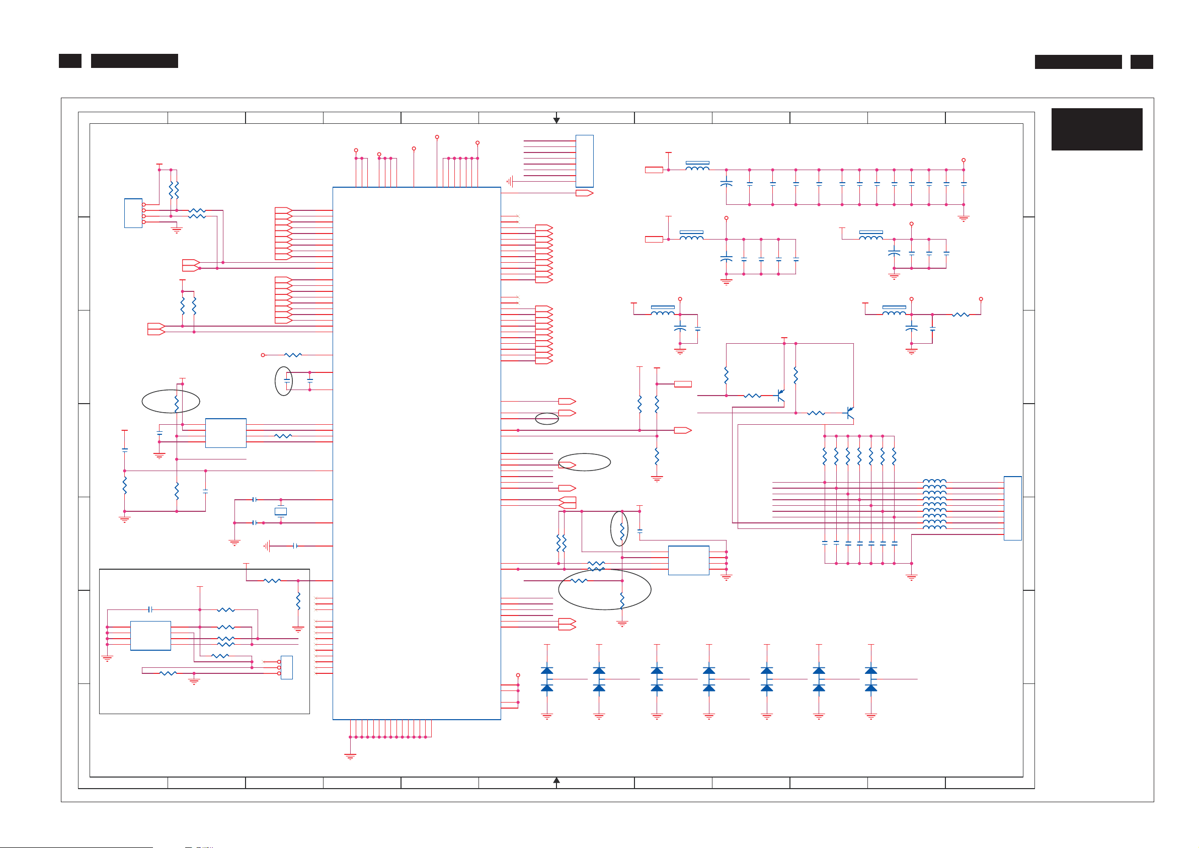
25
220VW8 LCD
Schematic Diagram(Scaler Board - Scaler)
220VW8 LCD
25
1
VCC3.3
2
A A
CN5
CN5
JWT-A2001WV2-04/NC
JWT-A2001WV2-04/NC
B
07/01/25 (READ EDID FAILED)
DDCD_SDA3
DDCD_SCL3
C C
+5V
D
C64
C64
R80
R80
10K/6
10K/6
1
2
3
4
10uF/8 6.3V
10uF/8 6.3V
DDCA_SDA3
DDCA_SCL3
C63
C63
0.1uF/6
0.1uF/6
R66
R66
3.3K/6/NC
3.3K/6/NC
R76
R76
10K/6
10K/6
R67
R67
4.7K/6/NC
4.7K/6/NC
4.7K/6/NC
4.7K/6/NC
R68 100/6/NCR68 100/6/NC
R69 100/6/NCR69 100/6/NC
VCC3.3
R70
R70
VCC3.3
R79
R79
10K/6/NC
10K/6/NC
RIN3
GNDR3
GIN
3
GNDG3
SOG3
BIN3
GNDB3
3
HSYNC
VSYNC3
3
3
3
R71
R71
3.3K/6/NC
3.3K/6/NC
ADD PULL HIGH RESISTOR 7 11 06
U5
U5
8
VDD
7
HOLD#
3
WP#
4
VSS
WP
C65
C65
0.22uF/6/NC
0.22uF/6/NC
CLK+3
3
AVDD_33
SST25VF010A
SST25VF010A
SDO
CE#
SCK
SDI
C66 22pF/6C66 22pF/6
14.318MHZ
14.318MHZ
C67 22pF/6C67 22pF/6
CLK-
2
1
6
5
E E
VDDP_33
NC
C70
C70
0.1uF/6/NC
0.1uF/6/NC
U7
U7
1
A0
A1
A2
GND4SDA
24C04/NC
24C04/NC
R104 0/6/NCR104 0/6/NC
VCC
SCL
2
F F
3
HDCP Key (288Bytes)
WP
VCC3.3
R98 10K/6/NCR98 10K/6/NC
8
7
6
5
R99 10K/6/NCR99 10K/6/NC
R100 100/6/NCR100 100/6/NC
R101 100/6/NCR101 100/6/NC
R102 10K/6/NCR102 10K/6/NC
R85 10K/6/NCR85 10K/6/NC
HDCP FUNCTION
G G
1
2
R+3
RG+
GB+3
B-3
R72 390/6 1%R72 390/6 1%
C78
C78
10uF/8/NC
10uF/8/NC
R77 0/6R77 0/6
X1
X1
HDCP_SCL
HDCP_SDA
HEADER4X1/NC
HEADER4X1/NC
3
JP1
JP1
1
2
3
3
C69
C69
C58
C58
0.1uF/6
0.1uF/6
0.1uF/6
0.1uF/6
R95
R95
10K/6
10K/6
108
128
127
102
110
111
115
116
117
118
U4
U4
28
27
25
24
26
23
22
32
33
34
35
9
10
12
13
15
16
18
19
5
6
7
31
30
41
42
43
44
37
57
56
55
61
64
70
67
4
AVDD_33
VDDC_18
8
14
20
AVDD_33
GND1GND
11
AVDD_33
AVDD_33
GND17GND29GND
52
VDDC53VDDC
GND72GND88GND
RIN0P
RIN0M
GIN0P
GIN0M
SOGIN0
BIN0P
BIN0M
HSYNC0
VSYNC0
DDCA_SDA/RS232_TX
DDCA_SCL/RS232_RX
RX2P
RX2N
RX1P
RX1N
RX0P
RX0N
RXCKP
RXCKN
DDCD_SDA
DDCD_SCL
REXT
REFP
REFM
SDO
CSZ
SCK
SDI
RST
XIN
XOUT
BYPASS
MODE
NC
NC
NC
NC
NC
NC
NC
NC
NC
NC
NC
NC
NC
4
5
MEMPLL_33
AVDD_18
104
74
126
21
58
AVDD_18
62
VDDP54VDDP
GND
113
VDDC
VDDC
TSUMU58WHJ-LF
TSUMU58WHJ-LF
GND
GND
GND68GND69GND63GND
101
106
105
5
6
VDDP_33
87
112
107
59
114
VDDP
VDDP
VDDP40VDDP
VDDP
GPIO_P14/PWM0
GPIO_P22/PWM1
GPIO_P24/PWM2
GPIO_P04
GPIO_P25
GPIO_P00/SAR0
GPIO_P01/SAR1
GPIO_P02/SAR2
GPIO_P03/SAR3
GPIO_P06
GPIO_P07
GPIO_P13/PWM2
GPIO_P15
GPIO_P16
http://www.wjel.net
VCTRL
VDDP
LVA4P
LVA4M
LVA3P
LVA3M
LVACKP
LVACKM
LVA2P
LVA2M
LVA1P
LVA1M
LVA0P
LVA0M
LVB4P
LVB4M
LVB3P
LVB3M
LVBCKP
LVBCKM
LVB2P
LVB2M
LVB1P
LVB1M
LVB0P
LVB0M
I2C_MCL
I2C_MDA
GPIO42
GPIO43
GPIO44
GPIO45
GPIO46
GPIO47
VDDP
VDDP
VDDP
VDDP
103
75
76
77
78
79
80
81
82
83
84
85
86
89
90
91
92
93
94
95
96
97
98
99
100
2
36
51
73
109
119
120
121
122
123
124
125
3
4
39
38
50
49
48
47
46
45
VDDP_33
60
65
66
71
7101-E08N
7101-E08N
HPD_CTRL
PWR
MENU
SEL
WP
LED_R
LED_G
HDCP_SCL
HDCP_SDA
HPD_CTRL
DOWN
UP
RIGHT
LEFT
MENU_O
SEL_O
PWR_O
DOWN_O
UP_O
LEDA_O
LEDG_O
LVA3P 5
LVA3M 5
LVACKP 5
LVACKM 5
LVA2P 5
LVA2M 5
LVA1P 5
LVA1M 5
LVA0P 5
LVA0M 5
LVB3P 5
LVB3M 5
LVBCKP 5
LVBCKM 5
LVB2P 5
LBA2M 5
LVB1P 5
LVB1M 5
LVB0P 5
LVB0M 5
R81
R81
3.3K/6
3.3K/6
D27
D27
12
DAN217K/NC
DAN217K/NC
R107 0/6R107 0/6
3
6
7
CN7
CN7
8
7
6
5
4
3
2
1
VOLUME 6
HPD_CTRL 3
on_BACKLIGHT 2
Adj_BACKLIGHT 2
DET_DVI 3
DET_VGA 3
R82
R82
3.3K/6
3.3K/6
R83 100/6R83 100/6
R84 100/6R84 100/6
MUTE 6
STBY 6
RIGHT_O MENU_O
VCC3.32,6
VCTRL 2
VCC1.82
VCC1.8
FB5
FB5
CX201209813/8
CX201209813/8
VCC3.3
VCC3.3
10K/6
10K/6
R106
R106
WP1
10K/6/NC
10K/6/NC
R108
R108
D28
D28
12
LEFT_O DOWN_O
3
DAN217K/NC
DAN217K/NC
7
+5V
R74 10K/6R74 10K/6
C68
C68
0.1uF/6
0.1uF/6
8
VCC3.3
VCC1.8
AVDD_18
R73 10K/6R73 10K/6
R78
R78
20K/6
20K/6
U6 24C16U6 24C16
8
VCC
7
WP
6
SCL
5
SDA
D29
D29
12
PWR_O
3
DAN217K/NC
DAN217K/NC
8
FB2
FB2
CX201209813/8
CX201209813/8
FB3
FB3
CX201209813/8
CX201209813/8
+
+
C59
C59
C60
C60
4.7uF/16V
4.7uF/16V
+5V 2,3,5
LED_R
LED_G
on_PANEL 5
A0
A1
A2
GND
VCC3.3 VCC3.3VCC3.3 VCC3.3VCC3.3VCC3.3VCC3.3
12
VDDC_18
0.1uF/6
0.1uF/6
1
2
3
4
D30
D30
3
DAN217K/NC
DAN217K/NC
+
+
C36
C36
10uF/35V
10uF/35V
+
+
4.7uF/16V
4.7uF/16V
C50
C50
R86
R86
10K/6
10K/6
R96 4.7K/6 1%R96 4.7K/6 1%
9
0.1uF/6
0.1uF/6
C37
C37
0.1uF/6
0.1uF/6
C54
C54
MMST3906
MMST3906
9
0.1uF/6
0.1uF/6
C38
C38
C39
C39
0.1uF/6
0.1uF/6
0.1uF/6
0.1uF/6
C55
C55
C56
C56
C57
C57
VCC3.3
R87
R87
10K/6
10K/6
Q7
Q7
R97 4.7K/6 1%R97 4.7K/6 1%
MENU
SEL
PWR
DOWN
UP
RIGHT
LEFT
D31
D31
12
SEL_O UP_O
3
DAN217K/NC
DAN217K/NC
0.1uF/6
0.1uF/6
0.1uF/6
0.1uF/6
10
0.1uF/6
0.1uF/6
C40
C40
VCC3.3
MMST3906
MMST3906
VCC3.3
R88 10K/6R88 10K/6
C710.1uF/6C710.1uF/6
D32
D32
12
3
DAN217K/NC
DAN217K/NC
10
Q8
Q8
R89 10K/6R89 10K/6
C720.1uF/6C720.1uF/6
C41
C41
0.1uF/6
0.1uF/6
R90 10K/6R90 10K/6
C730.1uF/6C730.1uF/6
C42
C42
C43
C43
0.1uF/6
0.1uF/6
0.1uF/6
0.1uF/6
FB4
FB4
CX201209813/8
CX201209813/8
VCC3.3
FB6
FB6
CX201209813/8/NC
CX201209813/8/NC
NC
R91 10K/6R91 10K/6
R92 10K/6R92 10K/6
R93 10K/6R93 10K/6
C760.1uF/6C760.1uF/6
C750.1uF/6C750.1uF/6
C740.1uF/6C740.1uF/6
D33
D33
12
3
DAN217K/NC
DAN217K/NC
11
C44
0.1uF/6
0.1uF/6
AVDD_33
+
+
10uF/35V
10uF/35V
C49
C49
R94 10K/6R94 10K/6
L2 1K/6L2 1K/6
L3 1K/6L3 1K/6
L4 1K/6L4 1K/6
L5 1K/6L5 1K/6
L6 1K/6L6 1K/6
L7 1K/6L7 1K/6
L8 1K/6L8 1K/6
L9 120/6L9 120/6
L10 82/6L10 82/6
C770.1uF/6C770.1uF/6 C44
11
VDDP_33
C48
C47
C47
0.1uF/6
0.1uF/6
0.1uF/6
0.1uF/6
0.1uF/6
0.1uF/6
0.1uF/6
0.1uF/6
C53
C53
C52
C52
VDDP_33MEMPLL_33
R75 0/6R75 0/6
C62
C62
0.1uF/6
0.1uF/6
C48
0.1uF/6
0.1uF/6
MENU_O
SEL_O
PWR_O
DOWN_O
UP_O
RIGHT_O
LEFT_O
LEDA_O
LEDG_O
4501-10-10P-R/NC
4501-10-10P-R/NC
+
+
C45
C45
0.1uF/6
0.1uF/6
0.1uF/6
0.1uF/6
C51
C51
C61
C61
10uF/16V/NC
10uF/16V/NC
C46
C46
TO BUTTON BOARD
12
12
CN6
CN6
10
9
8
7
6
5
4
3
2
1
B
D
S-A4
S-A3
CN5 A1
CN6 D12
CN7 A7
C36 A8
C36 D8
C37 A9
C38 A9
C39 A9
C40 A10
C41 A10
C42 A10
C43 A10
C44 A11
C45 A11
C46 A11
C47 A11
C48 A11
C49 B11
C50 B8
C51 B11
C52 B11
C53 B11
C54 B9
C55 B9
C56 B9
C57 B9
C58 C3
C59 C8
C60 C8
C61 C11
C62 C11
C63 D1
C64 D1
C65 D2
C66 D3
C67 E3
C68 E7
C69 E3
C70 E1
C71 E10
C72 E10
C73 E10
C74 E10
C75 E10
C76 E10
C77 E11
C78 C3
D27 F6
D28 F7
D29 F8
D30 F8
D31 F9
D32 F10
D33 F10
FB2 A8
FB3 B8
FB4 B10
FB5 B8
FB6 B10
JP1 F3
L2 D11
L3 D11
L4 D11
L5 D11
L6 D11
L7 D11
L8 E11
L9 E11
L10 E11
Q7 C9
Q8 C10
R66 A1
R67 A2
R68 A2
R69 A2
R70 B2
R71 B2
R72 C3
R73 C8
R74 C7
R75 B11
R76 C2
R77 D3
R78 D8
R79 D2
R80 D1
R81 E6
R82 E6
R83 E7
R84 E7
R85 E3
R86 C8
R87 C9
R88 D10
R89 D10
R90 D10
R91 D11
R92 D11
R93 D11
R94 D11
R95 F3
R96 C9
R97 D10
R98 F2
R99 F2
R100 F2
R101 F2
R102 F2
R104 F1
R106 E7
R107 E7
R108 F7
U4 A3
U5 D2
U6 E6
U7 F1
X1 E3
Page 26
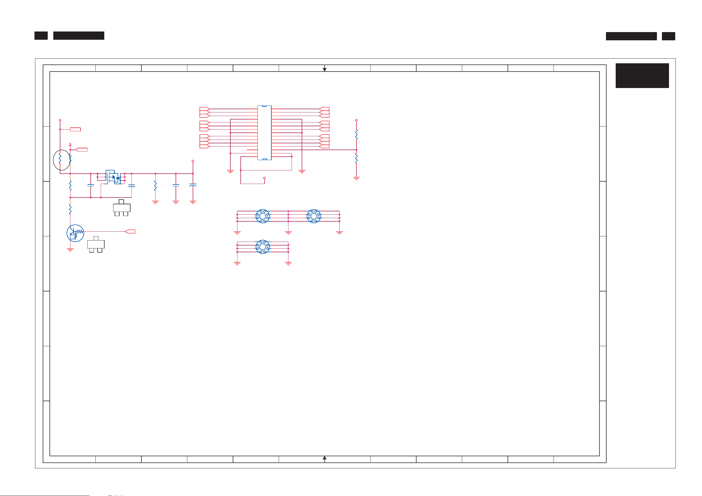
26
220VW8 LCD
Schematic Diagram(Scaler Board - Panel)
220VW8 LCD
26
1
2
A A
VCC12
VCC12 2,6
+5V
+5V 2,3,4
R20
B
C C
R20
CX201209813/8
CX201209813/8
R105
R105
CX201209813/8/NC
CX201209813/8/NC
R22
R22
10K/6
10K/6
R24
R24
2.2K/6
2.2K/6
31
C9
C9
2200PF/6
2200PF/6
Q5
Q5
DTC144EUA
DTC144EUA
2
C
3
2
B
Q4
2
3
4 5
SI9435Q4SI9435
D
2
G
1
E
81
7
6
C10
C10
2200PF/6
2200PF/6
3
1
S
on_PANEL 4
R23
R23
10K/6
10K/6
3
LVB0M4
LVB1M4
LVB2M4
LVBCKM4
LVB3M4
LVA0M4
LVA1M4
LVA2M4
4
LVACKM
LVA3M4
VPANEL
C11
C11
0.1uF/6
0.1uF/6
C12
C12
330U/16V
330U/16V
4
LVB0M
LVB1M
LVB2M RXO2-
LVBCKM RXOCLVB3M
LVA0M
LVA1M
LVACKM RXECLVA3M
RXO0RXO1-
RXO3RXE0-
RXE1RXE2-LVA2M
RXE3-
5
CN2
CN2
1
1
2
3
3
4
5
5
6
7
7
8
9
9
10
11
11
12
13
13
14
15
15
16
17
17
18
19
19
20
21
21
22
23
23
24
25
25
26
27
27
28
29
29
30
1841 30P
1841 30P
VPANEL
H1
H1
2
3
1
1
4
5 6
MTH276D126
MTH276D126
H3
H3
2
3
1
1
4
5
MTH276D126
MTH276D126
2
4
6
8
10
12
14
16
18
20
22
24
26
28
30
9
8
7
9
8
7
6
6
RXO0+ LVB0P
RXO1+ LVB1P
LVB2PRXO2+
RXOC+ LVBCKP
RXO3+ LVB3P
RXE0+ LVA0P
RXE1+ LVA1P
RXE2+ LVA2P
RXEC+ LVACKP
RXE3+ LVA3P
POL
H2
H2
2
3
4
5 6
MTH276D126
MTH276D126
7
LVB0P 4
LVB1P 4
LVB2P 4
LVBCKP 4
LVB3P 4
LVA0P 4
LVA1P 4
LVA2P 4
LVACKP 4
LVA3P 4
9
8
1
1
7
VPANEL
GND
R19
R19
3.6K/F/NC
3.6K/F/NC
R21
R21
1.2K/F/NC
1.2K/F/NC
8
9
10
11
12
D
S-A5
S-A3
CN2 A5
C9 B1
C10 B2
C11 B3
C12 B3
H1 B5
H1 C5
B
D
H2 C6
H3 B5
H3 C5
Q4 B2
Q5 C1
R19 B7
R20 B1
R21 B7
R22 B1
R23 B3
R24 C1
R105 B1
E E
http://www.wjel.net
F F
G G
1
2
3
4
5
6
7
8
9
10
11
12
Page 27
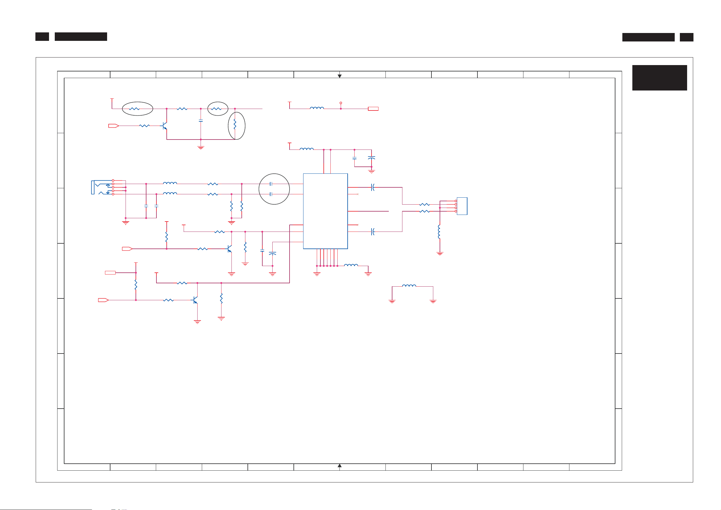
27
220VW8 LCD
Schematic Diagram(Scaler Board - Audio)
220VW8 LCD
27
1
+12V_A
A A
VOLUME4
2
AR1 1K/6/NCAR1 1K/6/NC
AR5 2K/6/NCAR5 2K/6/NC
2
PC
B
C C
D
E E
AUDIO-IN
AJ1
AJ1
ZD005D100/NC
ZD005D100/NC
VCC3.32,4
STBY4
1
5
4
3
2
MUTE4
AGND
AR13
AR13
10K/6/NC
10K/6/NC
L_LINE
R_LINE
VCC3.3
AL3 CX201209813/8/NCAL3 CX201209813/8/NC
1 2
1
AL4 CX201209813/8/NCAL4 CX201209813/8/NC
AC8
AC8
AC7
AC7
220pF/6/NC
220pF/6/NC
+12V_A
AR17 1K/6/NCAR17 1K/6/NC
3
AR2 10K/6/NCAR2 10K/6/NC
31
AQ1
AQ1
2N3904/NC
2N3904/NC
2
220pF/6/NC
220pF/6/NC
+12V_A
VCC3.3
AR12
AR12
10K/6/NC
10K/6/NC
AR14 10K/6/NCAR14 10K/6/NC
AGND
Z0415
Z0416
AR16 1K/6/NCAR16 1K/6/NC
AGND
AR3 10K/6/NCAR3 10K/6/NC
AC1
AC1
1uF/8/NC
1uF/8/NC
AR6 100/6/NCAR6 100/6/NC
AR7 100/6/NCAR7 100/6/NC
AR10 10K/6/NCAR10 10K/6/NC
AQ3
AQ3
MMST3906/NC
MMST3906/NC
AGND
4
AGND
AR15
AR15
10K/6/NC
10K/6/NC
AR4 3.9K/6/NCAR4 3.9K/6/NC
R25
R25
20K/6/NC
20K/6/NC
AGND
AQ2
AQ2
MMST3906/NC
MMST3906/NC
LIN_PC
RIN_PC
R26
R26
AGND
VOLU
20K/6/NC
20K/6/NC
AR11
AR11
10K/6/NC
10K/6/NC
5
+12V_A
AL1
AL1
+12V_A
AL2 CX201209813/8/NCAL2 CX201209813/8/NC
AC4 1uF/8/NCAC4 1uF/8/NC
AC6 1uF/8/NCAC6 1uF/8/NC
AC10
AC10
0.1uF/6/NC
0.1uF/6/NC
AC11
AC11
330U/16V/NC
330U/16V/NC
AGND AGND
4
9
11
12
10
TDA7496L/NC
TDA7496L/NC
AU1
AU1
INL
INR
STBY
MUTE
SVR
6
VCC12
CX201209813/8/NC
CX201209813/8/NC
16
VS15VS
OUTL
VAROUT_L
VOLUME
VAROUR_R
OUTR
GND
GND1GND2GND3GND19GND
GND
13
20
18
7
AC2
AC2
0.1uF/6/NC
0.1uF/6/NC
AGND
AC5
AC5
17
5
AC9
AC9
VOLU
GND
6
7
14
AL6 CX201209813/8/NCAL6 CX201209813/8/NC
VCC12 2,5
AC3
AC3
330U/16V/NC
330U/16V/NC
SPKOUTL
330U/16V/NC
330U/16V/NC
SPKOUTR
330U/16V/NC
330U/16V/NC
8
AR8 CX201209813/8/NCAR8 CX201209813/8/NC
AR9 CX201209813/8/NCAR9 CX201209813/8/NC
AGND
AL7 CX201209813/8/NCAL7 CX201209813/8/NC
GNDAGND
9
ACN1
ACN1
1
2
3
4
4606-04-04P-R/NC
4606-04-04P-R/NC
AL5
AL5
CX201209813/8/NC
CX201209813/8/NC
10
11
12
http://www.wjel.net
F F
S-A6
S-A3
ACN1 C9
AC1 A3
AC2 B7
AC3 B7
AC4 B5
AC5 B7
AC6 B5
AC7 C2
B
D
AC8 C2
AC9 C7
AC10 B5
AC10 C5
AC11 B5
AC11 D5
AJ1 B1
AL1 A6
AL2 B6
AL3 B3
AL4 B3
AL5 C8
AL6 D6
AL7 D8
AQ1 A3
AQ2 C4
AQ3 D3
AR1 A2
AR2 A3
AR3 A4
AR4 A4
AR5 A2
AR6 B4
AR7 B4
AR8 C8
AR9 C8
AR10 C4
AR11 C4
AR12 C3
AR13 D2
AR14 D3
AR15 D4
AR16 C3
AR17 D3
AU1 B6
R25 C4
R26 C4
G G
1
2
3
4
5
6
7
8
9
10
11
12
Page 28
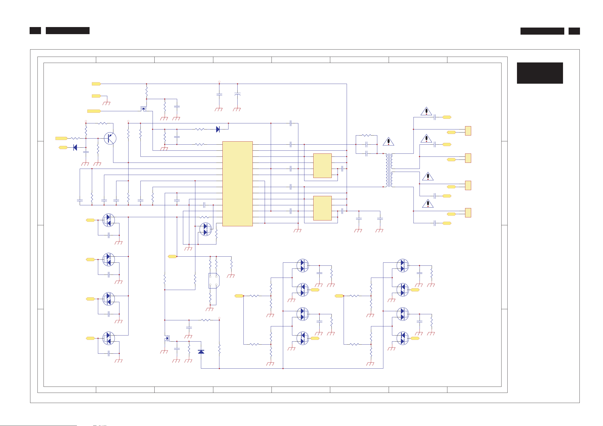
28
220VW8 LCD
Schematic Diagram(Power Board)
220VW8 LCD
28
7654321
D15
14
13
12
11
10
VCC
9
8
7
6
5
4
3
2
1
R8
C7
U1
LOK
ENSYNC
ABRT
DBRT
BRS
BRC
LCC
LCS
FT
AG
COMP
LV
LI
SI
C24
OUTL
VCCL
OUTR
VCCR
BTL
PRL
UGL
LGL
PGL
BTR
PRR
UGR
LGR
PGR
C31
C35
R13
23
22
25
24
26
27
28
16
15
18
17
19
20
21
C25
C27
C26
C28
U2
3
S2
4
G2
1
S1
2
G1
U3
3
S2
4
G2
1
S1
2
G1
6
D2
5
D2
C36
8
D1
7
D1
6
D2
5
D2
C37
8
D1
7
D1
C29
C30
C19 C20
T1
6.7
8
1
5
2.3
4
LV1
FB1
C32
LV2
FB2
FB3
C33
LV3
FB4
C34
LV4
Vin
IC_VCC
C1
ON/OFF
R40
C8
LV1
GND
R1
R41
R19
IC_VCC
R9R3R10
Q3
C4
C2
D1
C14
D
R12
DBRT
LI
D16
C
R2
G
D S
Q1
C3
R5
R4
C5
R6
C6
R7
R11
C18
C21
R42
D9
CN1
CN2
CN3
CN4
8
P-A
S-A3
C1 C1 JP10 B4
C2 C2 L1 C1
C3 C2 L1 B3
D
C4 C2 L1 B4
C5 D3 L1 B6
C6 D3 LV1 C1
C7 D4 LV1 D8
C8 C1 LV2 B1
1
2
C9 B5 LV2 C8
C10 A5 LV3 B1
C11 B7 LV3 C8
C12 A7 LV4 A1
C14 B2 LV4 C8
1
2
C15 B2 Q1 D2
C16 A2 Q2 A3
C17 A2 Q3 D2
C18 C3 R1 C1
C19 C6 R2 D2
C20 C6 R3 C2
1
2
C21 C3 R4 C3
C
C22 A3 R5 D3
C23 A3 R6 D3
C24 D4 R7 D3
C25 D5 R8 B4
C26 C5 R9 D2
1
2
C27 C5 R10 D2
C28 C5 R11 C3
C29 D6 R12 D1
C30 C6 R13 D6
C31 D7 R15 B3
C32 D7 R16 B3
C33 C7 R17 A3
C34 C7 R18 A3
C35 D5 R19 C2
D10 D12
R34
C9
D5
D11
D6
FB1
FB2
C10
R30
R23
R31
R35
R32
R24
R33
D7
D13
D8
FB3
FB4
C11
C12
R36
R37
R15
LI
214
R16
3
R43
R20
R39R38
JP10
R21
LI LI
R26
R27
http://www.wjel.net
IC_VCC
R17
C23
C22
R18
D14
R25
R28
R22
R29
Q2
D
G
S
LV2
B
A
D2
C15
LV3
D3
C16
LV4
D4
C17
C36 C6 R20 B4
C37 C6 R21 B4
CN1 D8 R22 A4
B
CN2 C8 R23 B6
CN3 C8 R24 A6
CN4 C8 R25 A4
D10 B5 R26 B5
D11 B5 R27 B5
D12 B7 R28 A5
D13 B7 R29 A5
D14 A3 R30 B6
D15 D4 R31 B6
D16 C1 R32 A6
D16 B2 R33 A6
D2 B2 R34 B6
D3 B2 R35 A6
D4 A2 R36 B7
D5 B5 R37 A7
D6 A5 R38 B3
D7 B7 R39 B4
D8 A7 R40 D1
A
D9 B3 R40 C2
FB1 B5 R41 D2
FB1 D8 R42 C3
FB2 A5 R43 B3
FB2 C8 T1 C7
FB3 B7 U1 D4
FB3 C8 U2 C5
1 2 3 4 5 6 78
FB4 A7 U3 C5
FB4 C8
Page 29
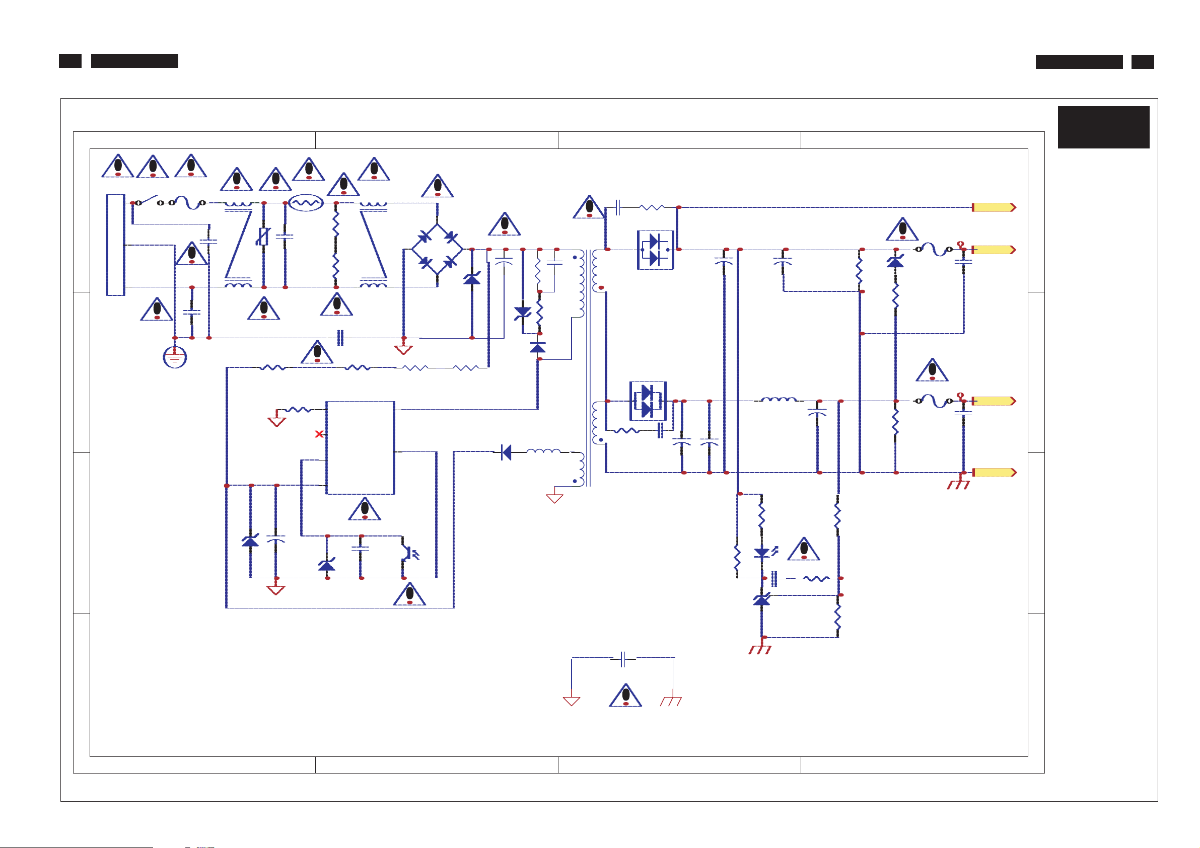
29
220VW8 LCD
Schematic Diagram(Power Board)
220VW8 LCD
29
P-B
BD101 D2
C114 D2
C115 D3
C120 B2
C123 B1
C231 B3
C240 C3
C241 B3
C242 C3
C243 C4
C244 B3
C260 D3
C261 D3
C263 D3
C264 D4
CN100 D1
CX101 D1
CY101 D1
CY102 C1
CY103 A3
CY104 C2
D110 C2
D120 C2
D240 C3
D260 D3
F101 D1
F240 C4
F260 D4
IC230 B3
K2 B3
L120 C2
L240 C3
LF101 D1
LF102 D2
PC201A B3
PC201B B2
R101 D2
R102 D2
R112 D2
R113 C2
R120 C2
R121 C2
R122 C2
R123 C1
R124 C1
R230 B3
R231 B3
R232 B4
R233 B4
R234 B4
R240 C3
R241 C4
R260 D3
R262 D4
R264 C4
SW101 D1
T101 D3
TH101 D1
U101 C2
VA101 D1
ZD110 D2
ZD111 D2
ZD120 B1
ZD121 B2
ZD260 D4
ZD260
R264
R241
4
F260
F240
INVERTER
D
+12V
+12V/0.8A
C264
C
+5V
+5V/2.5A
C243
RTN
B
A
321
CN100
D
FG
C
B
SW101
1
L
N
F101
LF101
2
1
CY101
4
CY102
1 2 34
2
VA101
3
R123
ZD120
+
R124
C123
TH101
CX101
CY104
6
5
4
3
ZD121
R101
R102
Ilimit
NC
FB
Vcc
2
3
R122
U101
LF102
Drain
C120
GND
1
BD101
2
4
4
3
1
2
PC201B
C260
3
4
ZD111
R112
C114
1
R120R121
+
D120
ZD110
R113
L120
D110
T101
1
9.10
C115
3
6.7
4
8
5
http://www.wjel.net
D240
R240
CY103
R260
D260
C240
+
C241
C261
+
C244
R231
C263
+
L240
R230
1
PC201A
2
K
A
C231
R
IC230
+
R262
+
C242
R234
R232
R233
Page 30
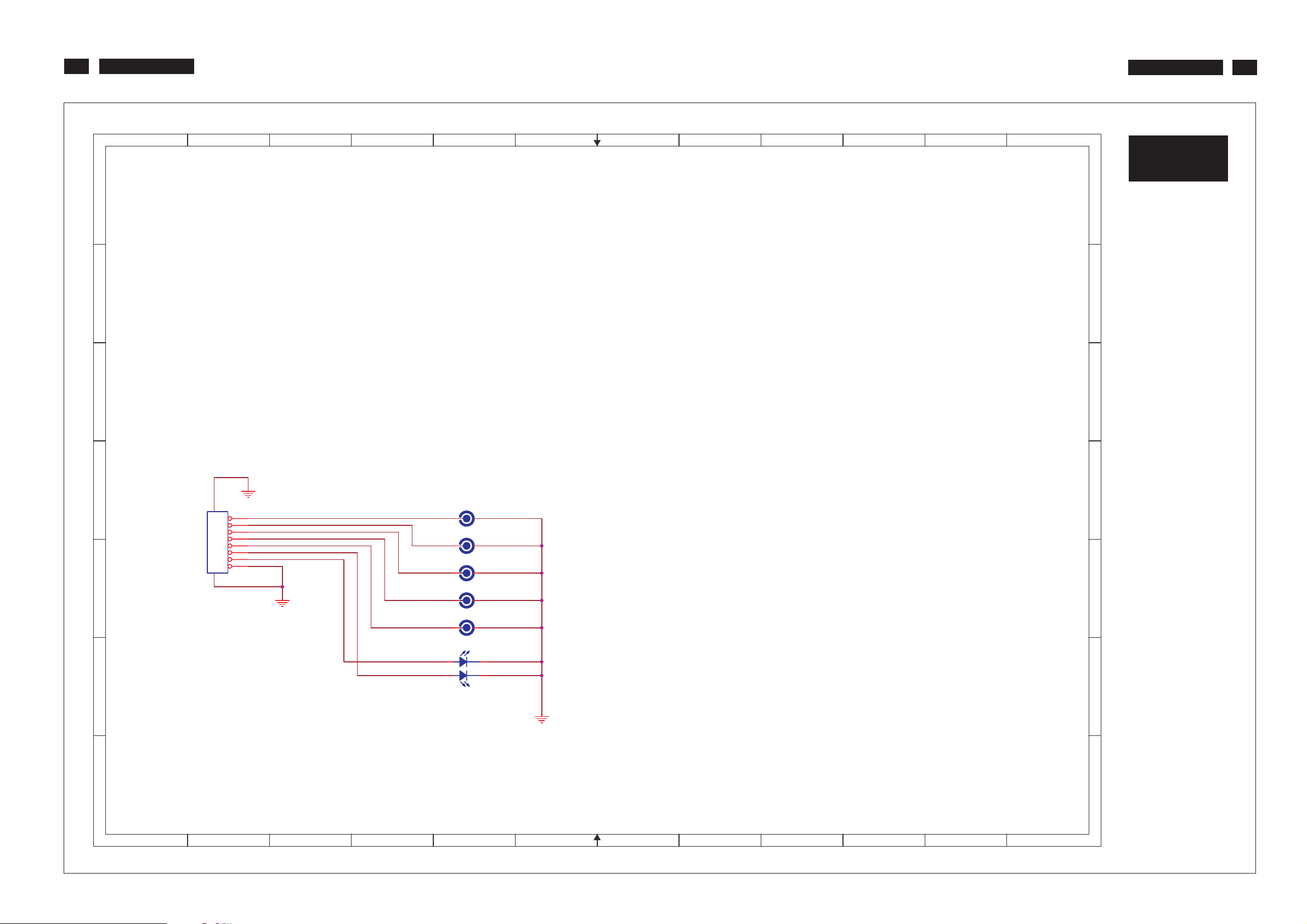
30
220VW8 LCD
Schematic Diagram(Buttom Board)
220VW8 LCD
30
1
A A
B
C C
2
3
4
5
6
7
8
9
10
11
12
B-1
B
D
E E
CON1
8
7
6
5
4
3
2
1
910
PH=1.0mm 8Pin/NC
MENU
SEL
PWR
RIGHT
LEFT
AMBER
GREEN
SW1 SW METALDOME
SW2 SW METALDOME
SW3 SW METALDOME
SW4 SW METALDOME
SW5 SW METALDOME
CON1 D2
SW1 D5
SW2 D5
SW3 E5
SW4 E5
SW5 E5
GREEN
3
4
12
F F
G G
LED1 KPTB-1612
http://www.wjel.net
AMBER
LED1 F5
D
1
2
3
4
5
6
7
8
9
10
11
12
Page 31
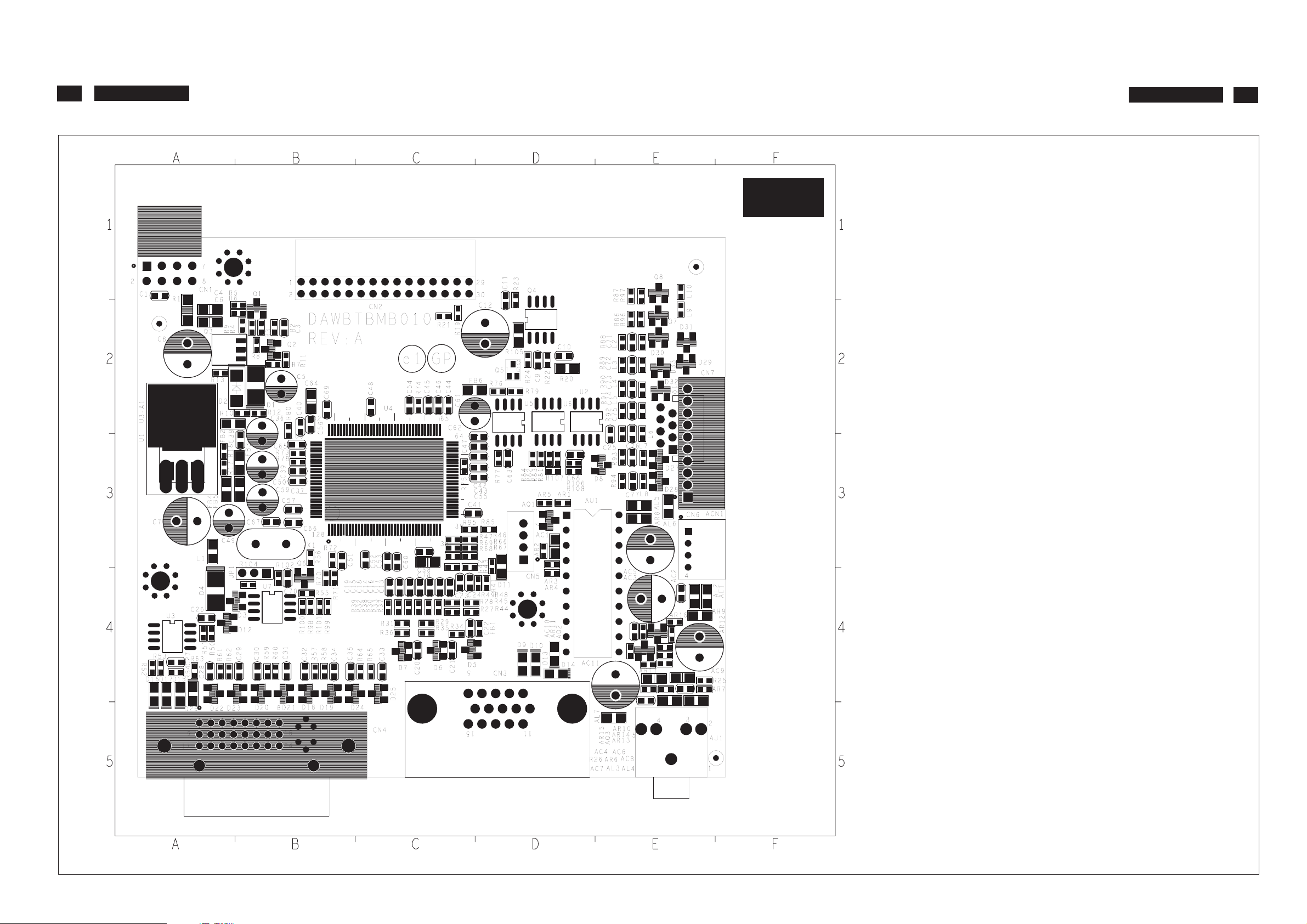
31
220VW8 LCD
Layout Side View(Scaler Board)
http://www.wjel.net
S-A
220VW8 LCD
AC1D3C11D1C61D2D26A4R18A2R69C2
AC2 E3 C12 D1 C62 D2 D27 E2 R19 C1 R70 B3
AC3 E4 C13 C2 C63 D2 D28 E3 R20 D2 R71 B3
AC4 E4 C14 C2 C64 B2 D29 E2 R21 C1 R72 B3
AC5 E3 C15 C2 C65 B2 D30 E1 R22 D2 R73 B2
AC6 E4 C16 C2 C66 B3 D31 E1 R23 D1 R74 C2
AC7 E4 C17 C2 C67 B3 D32 E2 R24 D2 R75 C2
AC8 E4 C18 C2 C68 D2 D33 E2 R25 E4 R76 D2
AC9 E4 C19 C2 C69 B2 FB1 D4 R26 E4 R77 D2
AC10 E4 C20 C4 C70 B3 FB2 A2 R27 C4 R78 B2
AC11 E4 C21 C4 C71 E1 FB 3 B2 R28 C4 R79 D2
ACN1 E3 C22 C4 C72 E2 FB4 A3 R29 C4 R80 B2
AJ1 E5 C23 C2 C73 E2 FB5 B3 R30 C4 R81 D2
AL1 E4 C24 C2 C74 E2 FB6 C2 R31 C4 R82 D2
AL2E4C25E2C75E2H1D4R32C4R83D2
AL3 E4 C26 A4 C76 E2 H2 A1 R33 C4 R84 D2
AL4 E4 C27 A4 C77 E3 H3 A3 R34 C4 R85 D3
AL5 E3 C28 A4 C78 C2 JP1 B3 R35 C4 R86 E1
AL6 E3 C29 B4 CN1 A1 L1 A3 R36 C4 R87 E1
AL7 E5 C30 B4 CN2 C1 L2 E1 R37 C4 R88 E1
AQ1D3C31B4CN3D4L3E2 R38C4R89E2
AQ2 E4 C32 B4 CN4 B5 L4 E2 R39 C4 R90 E2
AQ3 E4 C33 C4 CN5 D3 L5 E2 R41 D3 R91 E2
AR1 D3 C34 B4 CN6 E2 L6 E2 R42 C2 R92 E2
AR2 D3 C35 B4 CN7 E2 L7 E2 R43 C2 R93 E2
AR3 D3 C36 B2 D1 B2 L8 E3 R44 C4 R94 E3
AR4 D3 C37 B3 D2 B2 L9 E1 R45 C4 R95 C2
AR5 D3 C38 B2 D3 B4 L10 E1 R46 C2 R96 E1
AR6 E4 C39 B2 D4 A3 Q1 B1 R47 C2 R97 E1
AR7 E4 C40 B2 D5 C4 Q2 B1 R48 D3 R98 B4
AR8 E3 C41 C2 D6 C4 Q3 A1 R49 D3 R99 B4
AR9 E4 C42 D2 D7 C4 Q4 D1 R50 A4 R100 B4
AR10 E4 C43 D2 D8 E2 Q5 D2 R51 A4 R101 B4
AR11 E4 C44 C2 D9 D4 Q6 B3 R52 A4 R102 B3
AR12 E4 C45 C2 D10 D4 Q7 E1 R53 A4 R104 B3
AR13 E4 C46 C2 D11 D3 Q8 E1 R54 A4 R105 D1
AR14 E4 C47 D2 D12 A4 R1 A1 R55 B3 R106 D2
AR15 E4 C48 C2 D13 D4 R2 B1 R56 B3 R107 D2
AR16 E4 C49 A3 D14 D4 R3 B1 R57 B4 R108 D2
AR17 E4 C50 B2 D15 A4 R4 B1 R58 B4 U1 A2
AU1 D3 C51 B3 D16 A4 R5 B1 R59 B4 U2 D2
C1 A1 C52 C2 D17 A4 R6 B1 R60 B4 U3 A4
C3 B1 C53 C2 D18 B4 R7 B2 R61 A4 U3-A1 A2
C4 A1 C54 C2 D19 B4 R8 B1 R62 A4 U4 C2
C5 B2 C55 D3 D20 B4 R9 B1 R63 A4 U5 D2
C6 A1 C56 B2 D21 B4 R10 B2 R64 C4 U6 D2
C7 A3 C57 B3 D22 A4 R11 B2 R65 C4 U7 B4
C8 A1 C58 C2 D23 B4 R12 B2 R66 C2 X1 B3
C9 D2 C59 B3 D24 C4 R13 A2 R67 C2
C10 D1 C60 C2 D25 C4 R17 A2 R68 C2
31
Page 32
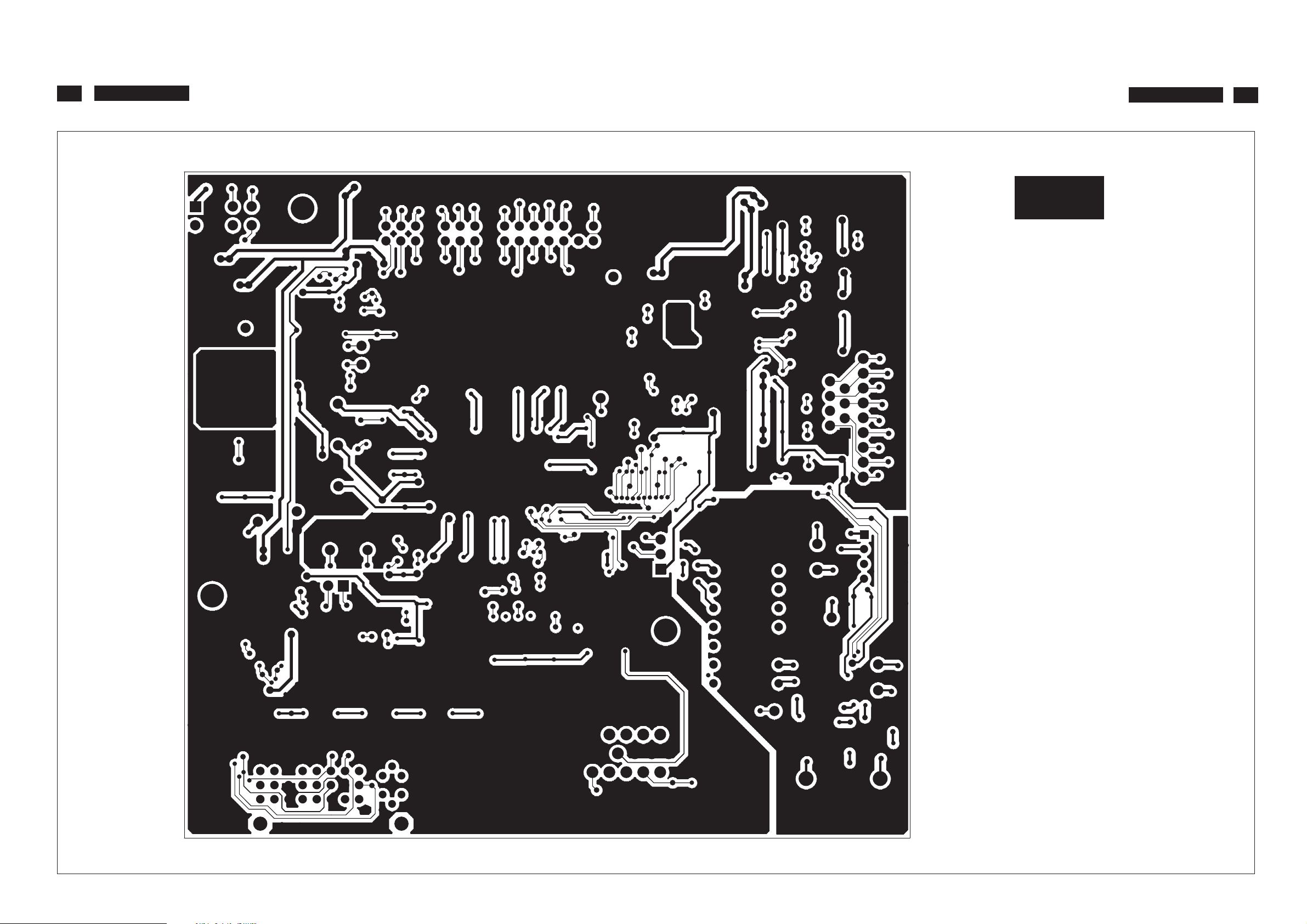
32
220VW8 LCD
Layout Side View(Scaler Board)
S-B
220VW8 LCD
32
http://www.wjel.net
Page 33
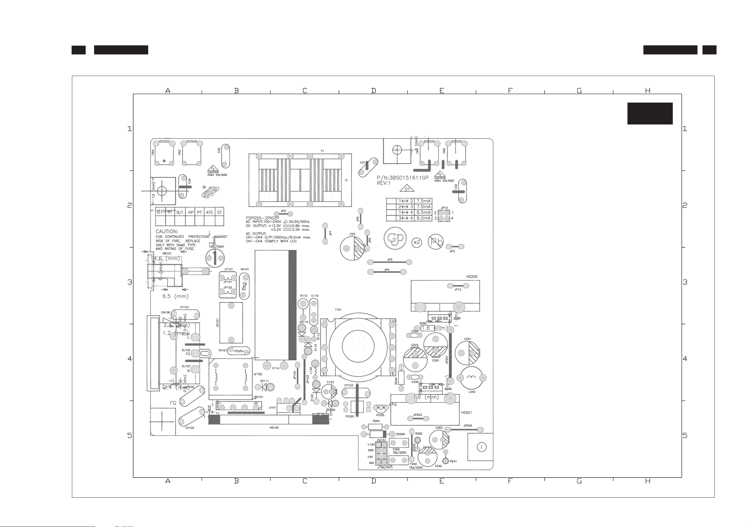
33
220VW8 LCD
Layout Side View(Power Board)
http://www.wjel.net
P-A
BD101 B5 IC230 D5
C24 D2 JP2 C2
C31 D1 JP3 E2
C32 E2 JP4 D3
C33 B1 JP5 D3
C34 A2 JP6 D2
C114 C3 JP7 C2
C115 C3 JP8 D2
C123 C4 JP101 B3
C240 E4 JP102 B3
C241 E4 JP103 C4
C242 E5 JP104 C4
C244 E4 JP12 E3
C260 E4 JP201 E4
C261 E4 JP202 E5
C263 E5 JP203 E5
CN1 E1 JP204 E5
CN2 E1 L101 B3
CN3 A1 L120 C4
CN4 A1 L240 E4
CN100 A4 LF102 B4
CN101 D5 PC201 D5
CX101 B3 R112 C3
CY101 A3 R113 C4
CY102 A4 R240 D4
CY103 D4 R240 E4
CY104 A5 R241 E5
D110 C4 R260 E4
D120 C4 R262 E5
D240 E4 R264 D5
D260 E3 SW101 A3
EL101 A4 T1 C1
EL102 A4 T101 D4
EL103 A4 TH101 B4
F101 B3 U101 C5
F240 D5 VA101 B3
F260 D5 ZD110 C4
HS100 B5 ZD111 B4
HS200 E3 ZD120 C5
HS201 E5 ZD260 D5
220VW8 LCD
33
Page 34
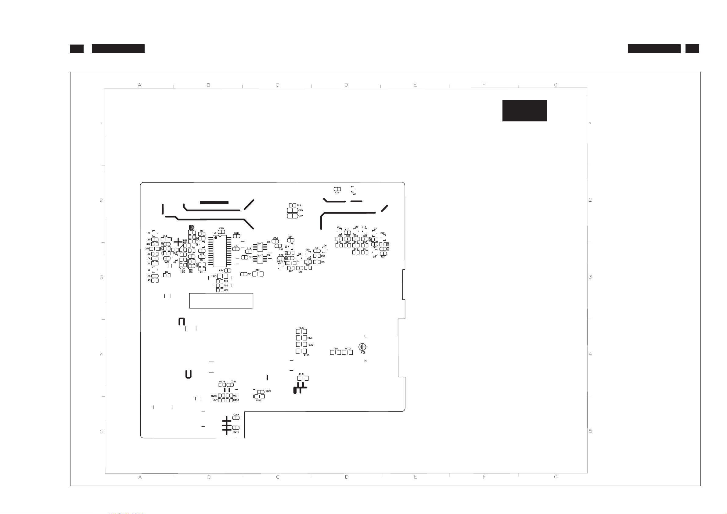
34
220VW8 LCD
Layout Side View(Power Board)
http://www.wjel.net
P-B
C1 B3 R5 A3
C2 B3 R6 A3
C4 B3 R7 A3
C5 A3 R8 B2
C6 A3 R9 B3
C7 C3 R10 B3
C8 A3 R11 B3
C9 D3 R12 A3
C10 D2 R13 C3
C11 E3 R15 B3
C12 D3 R16 B3
C14 C3 R17 C3
C15 A2 R18 C3
C16 D2 R19 B3
C17 E3 R20 B2
C18 B3 R21 D3
C19 C3 R22 D2
C20 B3 R23 D3
C21 B2 R24 D2
C22 C3 R25 C3
C23 C3 R26 C3
C25 B2 R27 C3
C26 B3 R28 D2
C27 C3 R29 D2
C28 B2 R30 D2
C29 C3 R31 D3
C30 C3 R32 D2
C35 A3 R33 D2
C35 B3 R34 D3
C36 C3 R35 D2
C37 C3 R36 E3
C120 C4 R37 D2
C231 B4 R38 B2
C243 B5 R39 B2
C264 B5 R40 A3
D1 C3 R41 A3
D2 A2 R42 B2
D3 D2 R43 B2
D4 D3 R101 D4
D5 C3 R102 D4
D6 D3 R120 C4
D7 D2 R121 C4
D9 B3 R122 C4
D10 C3 R123 C4
D11 D2 R124 C4
D12 E2 R230 B5
D13 D2 R231 B4
D14 C3 R232 B4
D15 A3 R233 B4
D16 A2 R234 B5
JP11 C3 U1 B2
JP13 B3 U2 C3
JP9 B3 U3 C3
Q1 A3 ZD121 C5
Q2 C3
Q3 B3
R1 B3
R2 A3
R3 B3
R4 B3
220VW8 LCD
34
Page 35
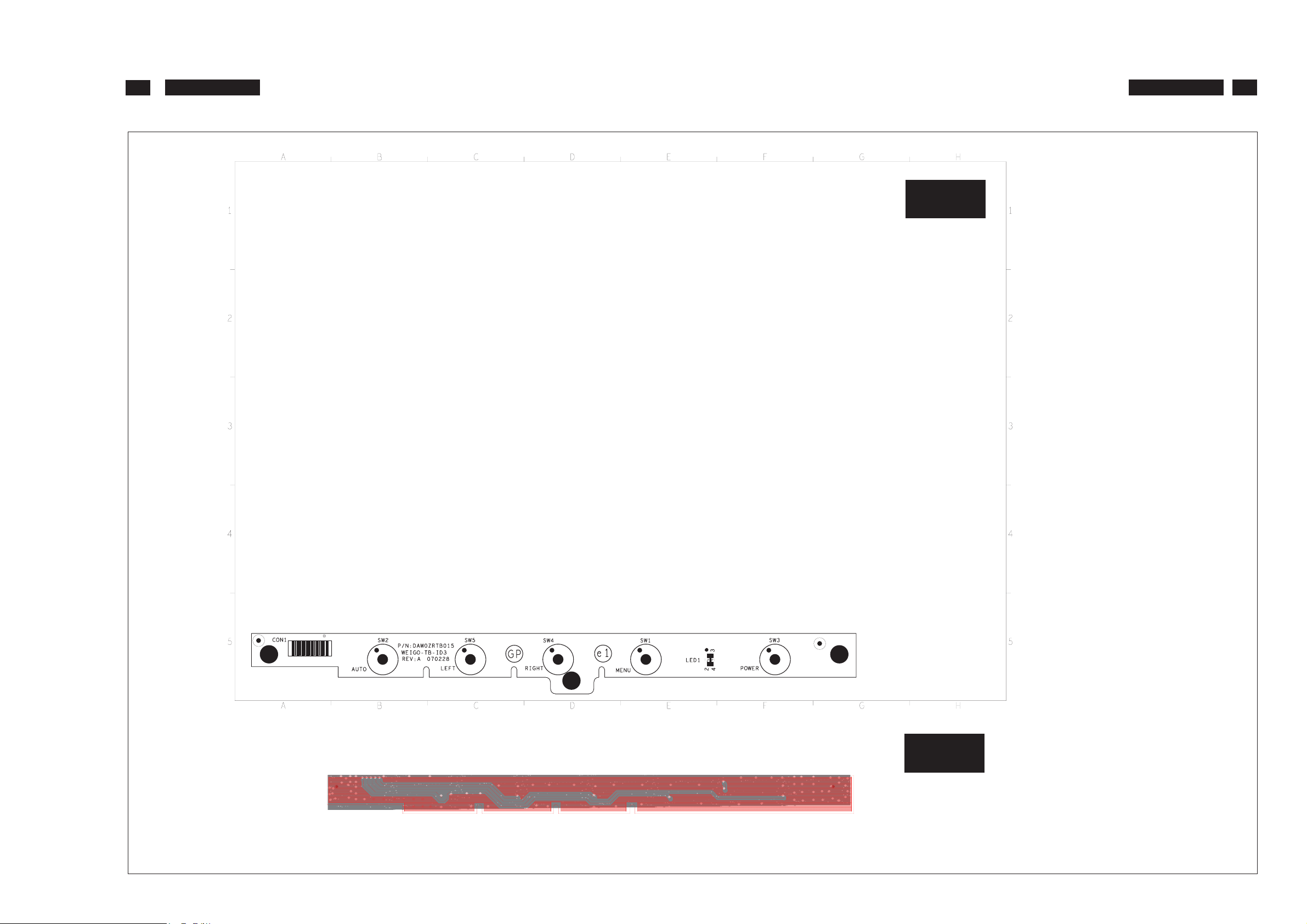
35
220VW8 LCD
Layout Side View(Button Board)
CON1 A5
LED2 B5
SW6 B5
SW5 C5
SW4 C5
SW3 D5
SW2 E5
SW1 F5
B-A
220VW8 LCD
35
LED1 F5
http://www.wjel.net
B-B
Page 36
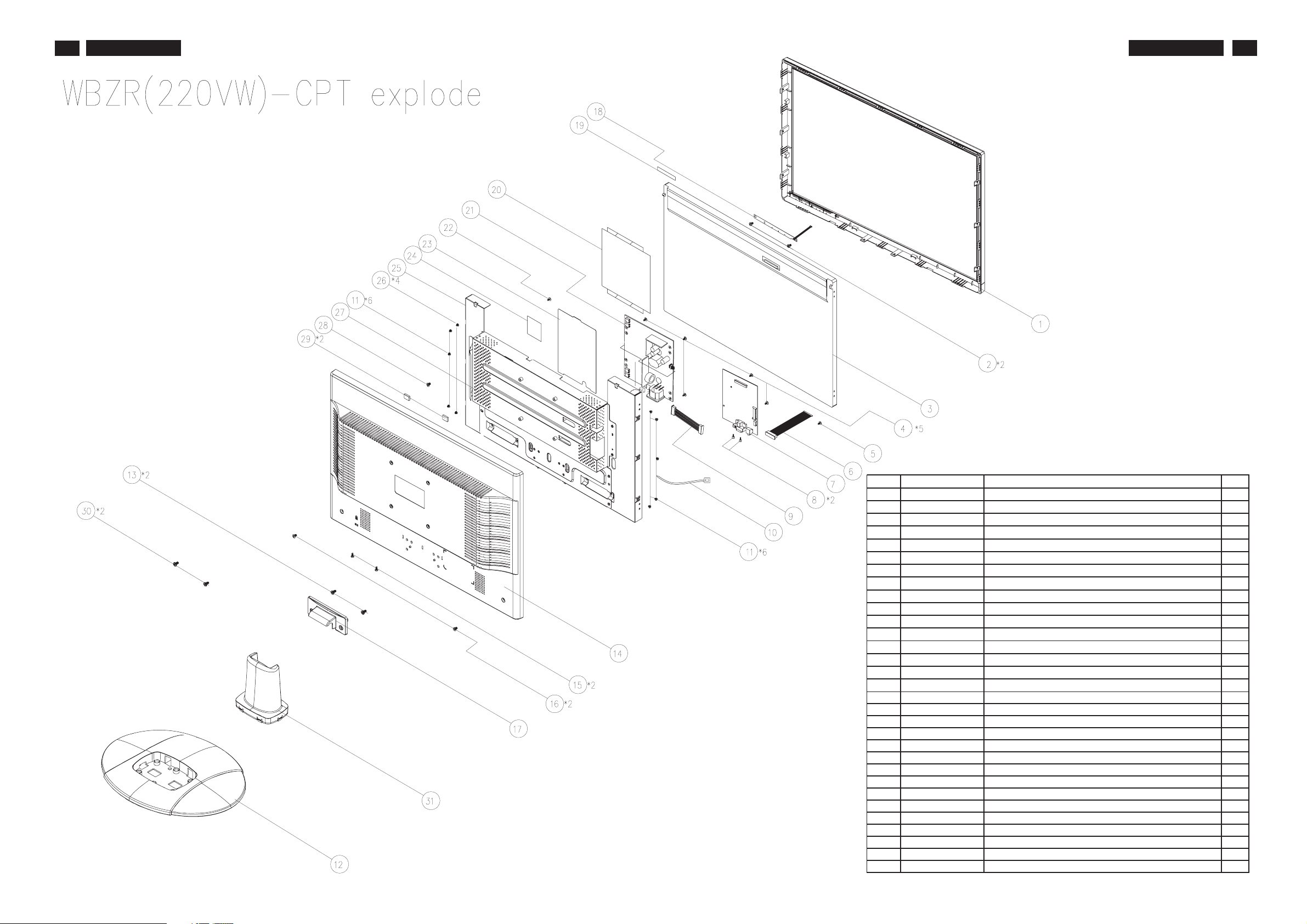
36
220VW8 LCD
Exploded View
220VW8 LCD
36
ITEM PART NO DESCRIPTION QTY
1
34WBZRLB0D0 WBZR LCD BZEZL SUB-ASSYCPT (B-V)GP 1
2
MF20025IBJ8 SCREW F2*2.5-I(NI) GP 2
3
AA0220WA001 LCD 22" CLAA220WA01(1680X1050,WSXGA ) GP 1
4
MF30060PBJ5 SCREW F3.0*6.0-P(NI)GP 5
5
MM30050BJ21 SCREW M3.0*5.0-B BLACK GP 1
6
DD0L9ELC030 CABLE LVDS(30P,150MM,LINKTEC AU)L9EA1 GP 1
7
10WBZRMB084 WBTB M/B ASSY(W0ZR-V1,TSUM58WHJ)A/ONLYGP 1
8
MBLI1004018 IO NUT LI1(MBLI1004,REV3A)GP 2
9
DDW0ZRPB008 CABLE MB-POWER/B(8P/8P,180MM)W0ZR GP 1
10
JXW0ZR07010 TIE W IRE W0ZR(JXW0ZR07,REV3A) GP 1
11
MM30040IBJ9 SCREW M3.0*4.0-I(NI) GP 6
12
38WBZRBS009 WBZR BASE SUB ASSY GP 1
13
MM40100FCI8 SCREW M4.0*10,F(NI,NYLOK) GP 2
14
http://www.wjel.net
EAWBZR12017 LCD COVER VGA WBZR(EAWBZR12,REV3A)GP 1
15
MM30050FJ26 SCREW M3.0*5-F(BNI) GP 2
16
MM30050B241 SCREW M3.0*5.0-B BLACK (NYLOK)GP 2
17
EBW0ZR05016 HINGE COVER W0ZR(EBW0ZR05,REV3A)GP 1
18
10WBZRBB003 W0ZR BUTTON/B ASSY(FOR WBZR) GP 1
19
FCW0ZR01011 BUTTON-BOARD-MYLAR W0ZR(FCW0ZR01,R3A)GP 1
20
FCWBZA01010 POWER MYLAR UP WBZA-L2(FCWBZA01,R3A)GP 1
21
AS05B5E0416 ADP/INV,FSP055-2PI02P(90V-264V)GP 1
22
MM40080BBW1 SCREW M4.0*8.0-B(NI,WASHER)GP 1
23
FCWBF001019 POWER MYLAR WBF-C1(FCWBF001,REV3A) GP 1
24
FCL9V005015 AL FOIL L9VDQ-4(FCL9V005,R3A)100*80 GP 1
25
FAWBZR09016 PCB SHIELD V WBZR(FAWBZR09,R3A) GP? 1
26
MM30050IBJ3 SCREW M3.0*5.0-I(NI) GP 4
27
FBWBZR01016 INVERTE R SHIELD WBZR(FBWBZR01,REV3A)GP 1
28
MM30030IBJ4 SCREW M3*3-I-NI GP 1
29
GAWBM001016 RUBBER WBM-B1(GAWBM001,REV3A)GP 2
30
MM40100B244 SCREW M4.0*10-B BLACK (NYLOK)GP 2
31
37WBZRSU000 WBZR STAND SUB ASSY GP 1
Page 37
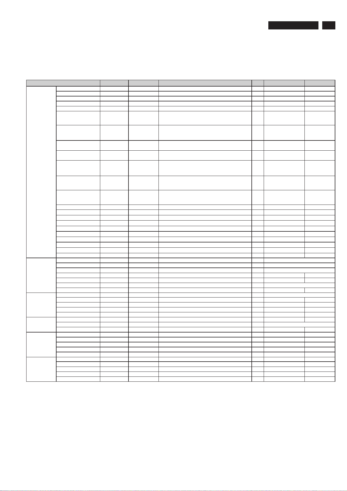
Recommended Spare Part List
RSPL FOR 220VW8FB/00(WBZR-V1C)
1 P/N: 1WBZRVPL051(CPT PANEL)
220VW8 LCD
37
Electronic
Components:
Mechanical
Components:
PCBA:
Cabinets:
Accessories:
Packing
Material:
Part Name
LCD panel 996510005565 AA0220WA001 LCD 22" CLAA220W A01(1680X1050,WSXGA ) GP 1 I tem 3 in exploded vi ew CPT PANEL
MB-LCD cable 996500044098 DD0L9ELC013 CABLE MB-LCD(30P,150MM)L9E-A1 GP 1
MB-LCD cable 996500044099 DD0L9ELC030 CABLE LVDS(30P,150MM,LINKTEC AU)L9EA1 GP 1 Item 6 in exploded view 2nd source
Button-MB cable DEFC5859011 CABLE FFC MB-BB(8P/8P,585MM)WBZR GP 1
Power-MB cable DDW0Z RPB008 CABLE MB-POW ER/B(8P/8P,180MM)W 0ZR GP 1 Item 9 in ex ploded v iew
IC 996510005354 AJU58WH^C09 IC(128P) TSUMU58W HJ-LF (165MHZ,PQFP) GP 1 U4
IC 996500044124 AKE10800R01 IC EEPROM(8P) BR24L16F-WE2(2K*8,SOP8)GP 1 U6
IC 996500044127 AKE258C0K04 IC(8P)FROM SST25VF010A-33-4C-SAE SOIC8GP 1 U5 Store programme
IC 996500044128 AKE25WC0P06 IC(8P)FLASH PM25LV010-33SCE(SOIC) GP 1 U5 Store programme
IC 996500044125 AKE3A8S0Y10 IC EEPROM(8P)24LC16BT-I(2K*8,100KHZ) GP 1 U6
IC 996500045091 AL001084021 IC(3P) AIC1084PE(TO-252) GP 1 U1
IC 996510008929 AL001084048 IC(3P) ME1084DTA (TO-252) GP 1 U1
TRANSISTOR 996500044113 BA001132Z05 TR,SMD 2SB1132PT(32V,1A) SOT 89 GP 1 Q3
TRANSISTOR 996500044114 BA001132Z13 TR,SMD 2SB1132T100R(32V,1A) SOT 89 GP 1 Q3
TRANSISTOR 996500044115 BA001440ZB8 TR CHDTC144EUPT(50V,30MA)SOT-323 GP 1 Q5
TRANSISTOR 996500044111 BA039040Z19 TR SMD PMBS3904(40V,200MA) GP 1 Q2
TRANSISTOR 996500044112 BA039040Z27 TR SMD SST3904(40V,200MA) GP 1 Q2
TRANSISTOR BA039060Z10 TR,SMD PMBS3906(40V,200MA) GP 3 Q1,Q7,Q8
TRANSISTOR 996510002084 BA039060Z28 TRANSISTOR,SMD SST3906(40V,200MA) GP 3 Q1,Q7,Q8
TRANSISTOR 996500044116 BA144EUAZ04 TRANSISTOR SMD DTC144EUA(50V,30MA) GP 1 Q5
TRANSISTOR 996500044117 BAM09435006 TR MOSFET ME9435A(-30V,-5.3A)SOIC8 GP 1 Q4
Stand 996500044100 37WBZRSU000 W BZR STAND SUB ASSY GP 1 Item 31 in exploded view
Base 996500044102 38WBZRBS009 WBZR BASE SUB ASSY GP 1 Item 12 in exploded v iew
Hinge cover 996500044101 EBW 0ZR05016 HINGE COVER W 0ZR(EBW0ZR05,REV3A)GP 1 Item 17 i n exploded view
DVI&D-SUB to shielding MBLI1004018 IO NUT LI1(MBLI1004,REV3A)GP 4 Item 8 in expl oded view
PCBAs to metal shielding MF30060PBJ5 SCREW F3.0*6.0-P(NI)GP 5 Item 4 in expl oded view
Panel to L/R bracket MM30040IBJ9 SCREW M3.0*4.0-I(NI) GP 6 Item 11 in expl oded view
Inverter board 996500044143 AS05B5E0416 ADP/INV,FSP055-2PI02P(90V-264V)GP 1 I tem 21 in exploded view
Main board 996510008749 10WBZRMB084 WBTB M/B ASSY(W0ZR-V1,TSUM58W HJ)A/ONLYGP 1 Item 7 in exploded view 21WBTBMB117
Bios 1 AZW BZRBC021 WBZR-V1A SW BIOS IMAGE(TSUMU58WHJ)CPT 1
Button board 996510006289 10WBZRBB003 W0ZR BUTTON/B ASSY(FOR WBZR) GP 1 Item 18 in exploded view 23W0ZRBB019
Front bezel 996510008727 34WBZRLB0D0 WBZR LCD BZEZL SUB-ASSYCPT (B-V)GP 1 Item 1 in exploded v i ew
Back cov er 996510008728 EAW BZR12017 LCD COVER VGA W BZR(EAWBZR12,REV3A)GP 1 Item 14 in exploded v iew
VGA cable 996510002083 DDL7ZI PC002 CABLE MB-VGA(15/15P,1.8M)BLACK L7ZI GP 1
Power cord 996500044109 DM333181801 PWR CORD B 1.8M SP-023/16A CT-12 EUR GP 1
Manual HGWBZR08015 CD+QSG W BZR-V1C(HGWBZR08,R3A)WW _GP 1
LCD film JXWBC001018 LCD FILM 495*325 W BC-B1(JXWBC001,R3A)GP 1
EPE bag HAW BZR01015 EPE BAG W BZR(HAWBZR01,R3A)GP 1
Carton 996510008730 HFW BZR32012 CARTON W BZR-V1C(HFWBZR32,R3A)WW_GP 1
Cushion 996510002309 HBW BZR01016 END CAP-L W BZR(HBWBZR01,REV3A)GP 1
Cushion 996510002310 HBW BZR02012 END CAP-R W BZR(HBWBZR02,REV3A)GP 1
PHILIPS P/N T echview P/N Description Q'ty Location Remark
Main IC,
programme
excutiv e
Store Timing
table ,HDCP KEY
information
Store Timing
table ,HDCP KEY
information
Power t ranslation,
other IC power
supply.
Power t ranslation,
other IC power
supply.
http://www.wjel.net
Page 38
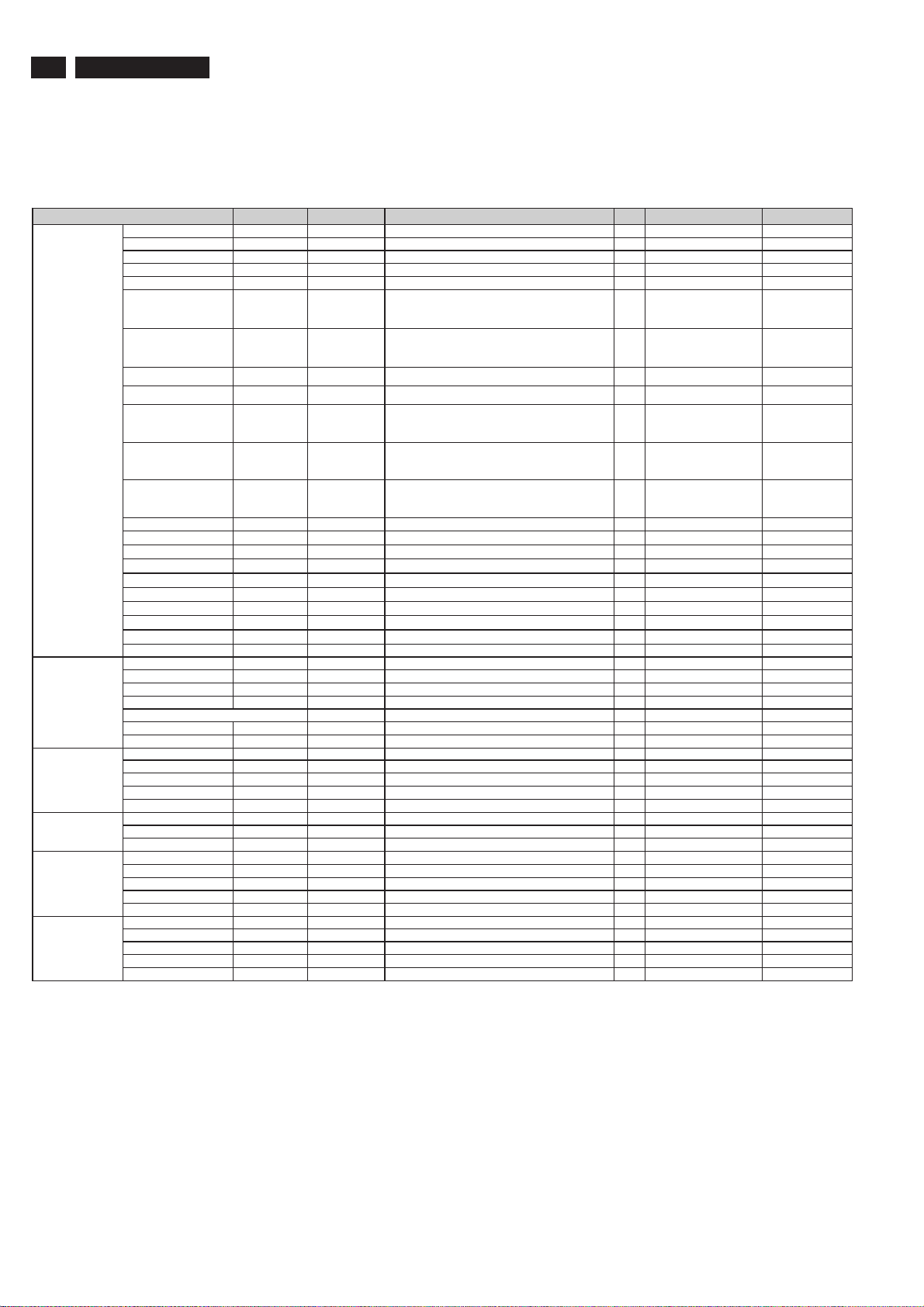
38
220VW8 LCD
RSPL FOR 220VW8FB/93(WBZR-V1C)
1 P/N: 1WBZRVPL069(CPT PANEL)
Spare Part List
Electronic
Components:
Mechanical
Components:
PCBA:
Cabinets:
Accessories:
Packing Material :
Part Name
LCD panel 996510005565 AA0220W A001 LCD 22" CLAA220WA01(1680X1050,WSXGA ) GP 1 Item 3 in ex ploded v iew CPT PANEL
MB-LCD cable 996500044098 DD0L9ELC013 CABLE MB-LCD(30P,150MM)L9E-A1 GP 1
MB-LCD cable 996500044099 DD0L9ELC030 CABLE LVDS(30P,150MM,LINKTEC AU)L9EA1 GP 1 I tem 6 in ex ploded v iew 2nd source
Button-MB cable DEFC5859011 CABLE FFC MB-BB(8P/8P,585MM)WBZR GP 1
Power-MB cable DDW0ZRPB008 CABLE MB-POWER/B(8P/8P,180MM)W 0ZR GP 1 Item 9 in exploded vi ew
IC 996510005354 AJU58WH^C09 IC(128P) TSUMU58W HJ-LF (165MHZ,PQFP) GP 1 U4
IC 996500044124 AKE10800R01 IC EEPRO M(8P) BR24L16F-W E2(2K*8,SOP8)GP 1 U6
IC 996500044127 AKE258C0K04 IC(8P)FROM SST25VF010A-33-4C-SAE SOIC8GP 1 U5 Store program me
IC 996500044128 AKE25WC0P06 I C(8P)FLASH PM25LV010-33SCE(SOIC) GP 1 U5 Store programme
IC 996500044125 AKE3A8S0Y10 IC EEPROM(8P)24LC16BT-I(2K*8,100KHZ) GP 1 U6
IC 996500045091 AL001084021 IC(3P) AIC1084PE(TO-252) GP 1 U1
IC 996510008929 AL001084048 IC(3P) ME1084DTA (TO-252) GP 1 U1
TRANSISTOR 996500044113 BA001132Z05 TR,SMD 2SB1132PT(32V,1A) SOT 89 GP 1 Q3
TRANSISTOR 996500044114 BA001132Z13 TR,SMD 2SB1132T100R(32V,1A) SOT 89 GP 1 Q3
TRANSISTOR 996500044115 BA001440ZB8 TR CHDTC144EUPT(50V,30MA)SOT-323 GP 1 Q5
TRANSISTOR 996500044111 BA039040Z19 TR SMD PMBS3904(40V,200MA) GP 1 Q2
TRANSISTOR 996500044112 BA039040Z27 TR SMD SST3904(40V,200MA) GP 1 Q2
TRANSISTOR 996500044110 BA039060Z10 TR,SMD PMBS3906(40V,200MA) GP 3 Q1,Q7,Q8
TRANSISTOR 996510002084 BA039060Z28 TRANSISTOR,SMD SST3906(40V,200MA) GP 3 Q1,Q7,Q8
TRANSISTOR 996500044116 BA144EUAZ04 TRANSISTO R SMD DTC144EUA(50V, 30MA) GP 1 Q5
TRANSISTOR 996500044117 BAM09435006 TR MOSFET ME9435A(-30V,-5.3A)SOIC8 GP 1 Q4
Stand 996500044100 37W BZRSU000 WBZR STAND SUB ASSY GP 1 Item 31 in exploded vi ew
Base 996500044102 38W BZRBS009 W BZR BASE SUB ASSY GP 1 Item 12 in exploded view
Hinge cover 996500044101 EBW 0ZR05016 HINGE COVER W 0ZR(EBW0ZR05,REV3A)GP 1 Item 17 in exploded v iew
DVI&D-SUB to shielding MBLI1004018 IO NUT LI1(MBLI1004,REV3A)GP 4 Item 8 in expl oded view
PCBAs to metal shielding MF30060PBJ5 SCREW F3.0*6.0-P(NI)GP 5 Item 4 in exploded v iew
Panel to L/R bracket MM30040IBJ9 SCREW M3.0*4.0-I(NI) GP 6 I tem 11 in exploded v iew
Inverter board 996500044143 AS05B5E0416 ADP/INV,FSP055-2PI02P(90V-264V)GP 1 Item 21 in exploded v iew
Main board 996510008749 10WBZRMB084 WBTB M/B ASSY(W 0ZR-V1,TSUM58WHJ)A/ONLYGP 1 Item 7 in exploded view 21W BTBMB117
Bios 1 AZWBZRBC021 W BZR-V1A SW BIOS IMAGE(TSUMU58WHJ)CPT 1
Button board 996510006289 10W BZRBB003 W 0ZR BUTTO N/B ASSY(FOR W BZR) GP 1 Item 18 in exploded view 23W0ZRBB019
Front bezel 34WBZRLB0B3 W BZR LCD BEZEL SUB ASSY (B-V)CPT CN GP 1 Item 1 in exploded v iew
Back cover 996510008728 EAW BZR12017 LCD COVER VGA W BZR(EAWBZR12,REV3A)GP 1 Item 14 in expl oded view
VGA cable 996510002083 DDL7ZI PC002 CABLE MB-VGA(15/ 15P,1.8M)BLACK L7ZI GP 1
Power cord 996500044139 DM333181S01 POW ER CORD B 1.8M SP-506/10A (CHN) GP 1
Manual HGW BZR08015 CD+QSG WBZR-V1C(HGWBZR08,R3A)WW_GP 1
LCD film JXWBC001018 LCD FILM 495*325 WBC-B1(JXWBC001,R3A)GP 1
EPE bag HAW BZR01015 EPE BAG W BZR(HAWBZR01,R3A)GP 1
Carton HFWBZR29011 CARTON W BZR-V1C(HFWBZ R29,R3A)CN GP 1
Cushion 996510006287 HBW BZR03019 CHINA END CAP-L WBZR(HBWBZR03,REV3A)GP 1
Cushion 996510006288 HBW BZR04015 CHINA END CAP-R WBZR(HBWBZR04,REV3A)GP 1
PHILIPS P/N Techview P/N Description Q'ty Location Remark
Main IC,
programme
excutiv e
Store Timing table
,HDCP KEY
information
Store Timing table
,HDCP KEY
information
Power t ranslation,
other IC power
supply.
Power t ranslation,
other IC power
supply.
http://www.wjel.net
Page 39
Recommended Spare Part List
RSPL FOR 220VW8FB/96(WBZR-V1C)
1 P/N: 1WBZRVPL077(CPT PANEL)
220VW8 LCD
39
Electronic
Components:
Mechanical
Components:
PCBA:
Cabinets:
Accessories:
Packing
Material:
Part Name
LCD panel 996510005565 AA0220WA001 LCD 22" CLAA220W A01(1680X1050,WSXGA ) GP 1 I tem 3 i n exploded view CPT PANEL
MB-LCD cable 996500044098 DD0L9ELC013 CABLE MB-LCD(30P,150MM)L9E-A1 GP 1
MB-LCD cable 996500044099 DD0L9ELC030 CABLE LVDS(30P,150MM,LINKTEC AU)L9EA1 GP 1 Item 6 in exploded vi ew 2nd source
Button-MB cable DEFC5859011 CABLE FFC MB-BB(8P/8P,585MM)WBZR GP 1
Power-MB cable DDW0ZRPB008 CABLE MB-POWER/B(8P/8P,180MM)W0ZR GP 1 Item 9 in exploded v iew
IC 996510005354 AJU58W H^C09 IC(128P) TSUMU58W HJ-LF (165MHZ,PQFP) GP 1 U4
IC 996500044124 AKE10800R01 IC EEPROM(8P) BR24L16F-W E2(2K*8,SOP8)GP 1 U6
IC 996500044127 AKE258C0K04 IC(8P)FROM SST25VF010A-33-4C-SAE SOIC8GP 1 U5 Store programme
IC 996500044128 AKE25W C0P06 IC(8P)FLASH PM25LV010-33SCE(SOIC) GP 1 U5 Store programm e
IC 996500044125 AKE3A8S0Y10 IC EEPROM(8P)24LC16BT-I(2K*8,100KHZ) GP 1 U6
IC 996500045091 AL001084021 IC(3P) AIC1084PE(T O-252) GP 1 U1
IC 996510008929 AL001084048 IC(3P) ME1084DTA (TO-252) GP 1 U1
TRANSISTOR 996500044113 BA001132Z05 TR,SMD 2SB1132PT(32V,1A) SO T 89 GP 1 Q3
TRANSISTOR 996500044114 BA001132Z13 TR,SMD 2SB1132T100R(32V,1A) SOT 89 GP 1 Q3
TRANSISTOR 996500044115 BA001440ZB8 TR CHDTC144EUPT(50V,30MA)SOT-323 GP 1 Q5
TRANSISTOR 996500044111 BA039040Z19 TR SMD PMBS3904(40V,200MA) GP 1 Q2
TRANSISTOR 996500044112 BA039040Z27 TR SMD SST3904(40V,200MA) GP 1 Q2
TRANSISTOR 996500044110 BA039060Z10 TR,SMD PMBS3906(40V,200MA) GP 3 Q1,Q7,Q 8
TRANSISTOR 996510002084 BA039060Z28 TRANSISTOR,SMD SST3906(40V,200MA) GP 3 Q1,Q7,Q8
TRANSISTOR 996500044116 BA144EUAZ04 TRANSISTOR SMD DTC144EUA(50V,30MA) GP 1 Q5
TRANSISTOR 996500044117 BAM09435006 TR MOSFET ME9435A(-30V,-5.3A)SOIC8 GP 1 Q4
Stand 996500044100 37WBZRSU000 W BZR STAND SUB ASSY GP 1 Item 31 in expl oded view
Base 996500044102 38W BZRBS009 W BZR BASE SUB ASSY GP 1 Item 12 in exploded view
Hinge cover 996500044101 EBW 0ZR05016 HINGE COVER W 0ZR(EBW0ZR05,REV3A)GP 1 Item 17 in exploded vi ew
DVI&D-SUB to shielding MBLI1004018 IO NUT LI1(MBLI1004,REV3A)GP 4 I tem 8 i n exploded view
PCBAs to metal shielding MF30060PBJ5 SCREW F 3.0*6.0-P(NI)GP 5 Item 4 in exploded v iew
Panel to L/R bracket MM30040IBJ9 SCREW M3.0*4.0-I(NI) GP 6 Item 11 in exploded v iew
Inverter board 996500044143 AS05B5E0416 ADP/INV,FSP055-2PI02P(90V-264V)GP 1 Item 21 in exploded v iew
Main board 996510008749 10WBZRMB084 WBTB M/B ASSY(W0ZR-V1,TSUM58WHJ)A/ONLYGP 1 Item 7 in exploded v iew 21WBTBMB117
Bios 1 AZW BZRBC021 W BZR-V1A SW BIOS IMAGE(TSUMU58WHJ)CPT 1
Button board 996510006289 10WBZRBB003 W0ZR BUTTON/B ASSY(FOR W BZR) GP 1 Item 18 in exploded vi ew 23W0ZRBB019
Front bezel 996510008727 34WBZRLB0D0 WBZR LCD BZEZL SUB-ASSYCPT (B-V)GP 1 Item 1 in exploded v iew
Back cover 996510008728 EAW BZR12017 LCD COVER VGA W BZR(EAWBZR12,REV3A)GP 1 Item 14 in exploded v iew
VGA cable 996510002083 DDL7ZIPC002 CABLE MB-VGA(15/15P,1.8M)BLACK L7ZI GP 1
Power cord 996510008729 DM33T181004 PW R CORD B 1.8M SP-305/7A TAIWAN GP 1
Manual HGWBZR08015 CD+QSG WBZR-V1C(HGWBZR08,R3A)W W_GP 1
LCD film JXWBC001018 LCD FILM 495*325 WBC-B1(JXWBC001,R3A)GP 1
EPE bag HAW BZR01015 EPE BAG W BZR(HAWBZR01,R3A)GP 1
Carton 996510008730 HFWBZR32012 CARTON W BZR-V1C(HFWBZR32,R3A)WW_GP 1
Cushion 996510002309 HBWBZR01016 END CAP-L WBZR(HBWBZR01,REV3A)GP 1
Cushion 996510002310 HBWBZR02012 END CAP-R WBZR(HBWBZR02,REV3A)GP 1
PHILIPS P/N Techview P/N Description Q'ty Location Remark
Main IC,
programme
excutiv e
Store Timing table
,HDCP KEY
information
Store Timing table
,HDCP KEY
information
Power t ranslation,
other IC power
supply.
Power t ranslation,
other IC power
supply.
http://www.wjel.net
Page 40

40
O
220VW8 LCD
Spare Part List
>> MAIN BOARD ASSY
WBTB M/B ASSY(W0ZR-V1,TSUM58WHJ)A/ONLYGP
21WBTBMB117 W0ZR-V1 MB Schematic(TSUMU58WHJ)A/
WBTB M/B S/S ASSY(W0ZR-V1,TSUM58WHJ)GP
PCB(M/B)WBTB (2L,98*90 REVA)T SUMU58WJ GP
U4 IC(128P) TSUMU58WHJ-LF (165MHZ,PQFP) GP
U1 IC(3P) AIC1084PE(TO-252) GP
U1 IC(3P) ME1084DTA (TO-252) GP
Q3 TR,SMD 2SB1132PT(32V,1A) SOT 89 GP
Q3 TR,SMD 2SB1132T100R(32V,1A) SOT 89 GP
U6 IC EEPROM(8P) BR24L16F-WE2(2K*8,SOP8)GP
U6 IC EEPROM(8P)24LC16BT-I(2K*8,100KHZ) GP
U5 IC(8P)FROM SST25VF010A-33-4C-SAE SOIC8GP
U5 IC(8P)FLASH PM25LV010-33SCE(SOIC) GP
Q2 TR SMD PMBS3904(40V,200MA) GP
Q2 TR SMD SST3904(40V,200MA) GP
Q1 TR,SMD PMBS3906(40V,200MA) GP
Q7 TR,SMD PMBS3906(40V,200MA) GP
Q8 TR,SMD PMBS3906(40V,200MA) GP
Q1 TRANSISTOR,SMD SST3906(40V,200MA) GP
Q7 TRANSISTOR,SMD SST3906(40V,200MA) GP
Q8 TRANSISTOR,SMD SST3906(40V,200MA) GP
D2 DIODE,SMD LL4148PT (75V,0.15A) GP
D2 DIODE,SMD RLS4148 GP
D1 DIODE SSM12LLPT(20V,1A,VF:0.27V)SMA GP
D4 DIODE SSM12LLPT(20V,1A,VF:0.27V)SMA GP
Q4 TR MOSFET ME9435A(-30V,-5.3A)SOIC8 GP
Q5 TR CHDTC144EUPT(50V,30MA)SOT-323 GP
Q5 TRANSISTOR SMD DTC144EUA(50V,30MA) GP
D3 DIODE SMD BAT54C(30V,200MA,SCHOTTKY)GP
C66 CAP CHIP 22P 50V(+-5%,NPO,0603) GP
C67 CAP CHIP 22P 50V(+-5%,NPO,0603) GP
C23 CAP CHIP 33P 50V(+-5%,NPO,0603)GP
C24 CAP CHIP 33P 50V(+-5%,NPO,0603)GP
L9 RES CHIP 33 1/10W +-5%(0603) GP
L10 RES CHIP 33 1/10W +-5%(0603) GP
C9 CAP CHIP 2200P 50V(+-10%,X7R,0603)GP
C10 CAP CHIP 2200P 50V(+-10%,X7R,0603)GP
C13 CAP CHIP 0.047UF 16V(+-10%,X7R,0603) GP
C14 CAP CHIP 0.047UF 16V(+-10%,X7R,0603) GP
C15 CAP CHIP 0.047UF 16V(+-10%,X7R,0603) GP
C17 CAP CHIP 0.047UF 16V(+-10%,X7R,0603) GP
C18 CAP CHIP 0.047UF 16V(+-10%,X7R,0603) GP
C19 CAP CHIP 0.047UF 16V(+-10%,X7R,0603) GP
C16 CAP CHIP 0.01U 50V(+-10%,X7R,0603) GP
C1 CAP CHIP 0.1U,25V(+80-20%,Y5V,0603) GP
C11 CAP CHIP 0.1U,25V(+80-20%,Y5V,0603) GP
C37 CAP CHIP 0.1U,25V(+80-20%,Y5V,0603) GP
C38 CAP CHIP 0.1U,25V(+80-20%,Y5V,0603) GP
C39 CAP CHIP 0.1U,25V(+80-20%,Y5V,0603) GP
C40 CAP CHIP 0.1U,25V(+80-20%,Y5V,0603) GP
C41 CAP CHIP 0.1U,25V(+80-20%,Y5V,0603) GP
C42 CAP CHIP 0.1U,25V(+80-20%,Y5V,0603) GP
C43 CAP CHIP 0.1U,25V(+80-20%,Y5V,0603) GP
C44 CAP CHIP 0.1U,25V(+80-20%,Y5V,0603) GP
C45 CAP CHIP 0.1U,25V(+80-20%,Y5V,0603) GP
C46 CAP CHIP 0.1U,25V(+80-20%,Y5V,0603) GP
C47 CAP CHIP 0.1U,25V(+80-20%,Y5V,0603) GP
C48 CAP CHIP 0.1U,25V(+80-20%,Y5V,0603) GP
C51 CAP CHIP 0.1U,25V(+80-20%,Y5V,0603) GP
C52 CAP CHIP 0.1U,25V(+80-20%,Y5V,0603) GP
C53 CAP CHIP 0.1U,25V(+80-20%,Y5V,0603) GP
C54 CAP CHIP 0.1U,25V(+80-20%,Y5V,0603) GP
C55 CAP CHIP 0.1U,25V(+80-20%,Y5V,0603) GP
C56 CAP CHIP 0.1U,25V(+80-20%,Y5V,0603) GP
C57 CAP CHIP 0.1U,25V(+80-20%,Y5V,0603) GP
C58 CAP CHIP 0.1U,25V(+80-20%,Y5V,0603) GP
C60 CAP CHIP 0.1U,25V(+80-20%,Y5V,0603) GP
C62 CAP CHIP 0.1U,25V(+80-20%,Y5V,0603) GP
C63 CAP CHIP 0.1U,25V(+80-20%,Y5V,0603) GP
C68 CAP CHIP 0.1U,25V(+80-20%,Y5V,0603) GP
C69 CAP CHIP 0.1U,25V(+80-20%,Y5V,0603) GP
C71 CAP CHIP 0.1U,25V(+80-20%,Y5V,0603) GP
C72 CAP CHIP 0.1U,25V(+80-20%,Y5V,0603) GP
C73 CAP CHIP 0.1U,25V(+80-20%,Y5V,0603) GP
C74 CAP CHIP 0.1U,25V(+80-20%,Y5V,0603) GP
C75 CAP CHIP 0.1U,25V(+80-20%,Y5V,0603) GP
C76 CAP CHIP 0.1U,25V(+80-20%,Y5V,0603) GP
C77 CAP CHIP 0.1U,25V(+80-20%,Y5V,0603) GP
C4 CAP CHIP 1UF 25V(+-20%,Y5V,0805) GP
C64 CAP CHIP 10UF 10V(+-20%,Y5V,0805)GP
R1 RES CHIP 0 1/4W+-5%(3216) GP
FB1 RES CHIP 0 1/10W+-5%(0603) GP
DAWBTBMB010 WBTB MB Gerber file & Board File
http://www.wjel.net
R2 RES CHIP 0 1/10W+-5%(0603) GP
R9 RES CHIP 0 1/10W+-5%(0603) GP
R10 RES CHIP 0 1/10W+-5%(0603) GP
R75 RES CHIP 0 1/10W+-5%(0603) GP
R77 RES CHIP 0 1/10W+-5%(0603) GP
R107 RES CHIP 0 1/10W+-5%(0603) GP
R7 RES CHIP 47 1/10W +-5%(0603) GP
R27 RES CHIP 56 1/10W +-1%(0603) GP
R29 RES CHIP 56 1/10W +-1%(0603) GP
R31 RES CHIP 56 1/10W +-1%(0603) GP
R34 RES CHIP 75 1/10W +-1%(0603) GP
R35 RES CHIP 75 1/10W +-1%(0603) GP
R36 RES CHIP 75 1/10W +-1%(0603) GP
R37 RES CHIP 100 1/10W+-1%(0603)GP
R38 RES CHIP 100 1/10W+-1%(0603)GP
R39 RES CHIP 100 1/10W+-1%(0603)GP
R13 RES CHIP 100 1/10W +-5%(0603) GP
R48 RES CHIP 100 1/10W +-5%(0603) GP
R49 RES CHIP 100 1/10W +-5%(0603) GP
R83 RES CHIP 100 1/10W +-5%(0603) GP
R84 RES CHIP 100 1/10W +-5%(0603) GP
R17 RES CHIP 200 1/10W+-1%(0603) GP
R18 RES CHIP 330 1/10W +-1%(0603) GP
R72 RES CHIP 390 1/10W+-1%(0603) GP
R33 RES CHIP 470 1/10W+-5%(0603) GP
L2 RES CHIP 1K 1/10W +-5%(0603) GP
L3 RES CHIP 1K 1/10W +-5%(0603) GP
L4 RES CHIP 1K 1/10W +-5%(0603) GP
L5 RES CHIP 1K 1/10W +-5%(0603) GP
L6 RES CHIP 1K 1/10W +-5%(0603) GP
L7 RES CHIP 1K 1/10W +-5%(0603) GP
L8 RES CHIP 1K 1/10W +-5%(0603) GP
R4 RES CHIP 1K 1/10W +-5%(0603) GP
R8 RES CHIP 1K 1/10W +-5%(0603) GP
R42 RES CHIP 1K 1/10W +-5%(0603) GP
R43 RES CHIP 1K 1/10W +-5%(0603) GP
R12 RES CHIP 2K 1/10W +-5%(0603) GP
R11 RES CHIP 2.2K 1/10W,+-1%(0603) GP
R24 RES CHIP 2.2K 1/10W,+-1%(0603) GP
R44 RES CHIP 2.2K 1/10W,+-1%(0603) GP
R45 RES CHIP 2.2K 1/10W,+-1%(0603) GP
R81 RES CHIP 3.3K 1/10W +-5%(0603) GP
R82 RES CHIP 3.3K 1/10W +-5%(0603) GP
R78 RES CHIP 20K 1/10W +-1%(0603) GP
R96 RES CHIP 4.7K 1/10W+-1%(0603) GP
R97 RES CHIP 4.7K 1/10W+-1%(0603) GP
R28 EMI FILT CHP FCM1608CF-300T06 30,0.6A GP
R30 EMI FILT CHP FCM1608CF-300T06 30,0.6A GP
R32 EMI FILT CHP FCM1608CF-300T06 30,0.6A GP
R3 RES CHIP 10K 1/10W +-5%(0603) GP
R5 RES CHIP 10K 1/10W +-5%(0603) GP
R6 RES CHIP 10K 1/10W +-5%(0603) GP
R22 RES CHIP 10K 1/10W +-5%(0603) GP
R23 RES CHIP 10K 1/10W +-5%(0603) GP
R73 RES CHIP 10K 1/10W +-5%(0603) GP
R74 RES CHIP 10K 1/10W +-5%(0603) GP
R76 RES CHIP 10K 1/10W +-5%(0603) GP
R80 RES CHIP 10K 1/10W +-5%(0603) GP
R86 RES CHIP 10K 1/10W +-5%(0603) GP
R87 RES CHIP 10K 1/10W +-5%(0603) GP
R88 RES CHIP 10K 1/10W +-5%(0603) GP
R89 RES CHIP 10K 1/10W +-5%(0603) GP
R90 RES CHIP 10K 1/10W +-5%(0603) GP
R91 RES CHIP 10K 1/10W +-5%(0603) GP
R92 RES CHIP 10K 1/10W +-5%(0603) GP
R93 RES CHIP 10K 1/10W +-5%(0603) GP
R94 RES CHIP 10K 1/10W +-5%(0603) GP
R95 RES CHIP 10K 1/10W +-5%(0603) GP
R106 RES CHIP 10K 1/10W +-5%(0603) GP
FB2 EMI FILT CHIP FBMA-11-201209-121A40 GP
FB3 EMI FILT CHIP FBMA-11-201209-121A40 GP
FB4 EMI FILT CHIP FBMA-11-201209-121A40 GP
FB5 EMI FILT CHIP FBMA-11-201209-121A40 GP
L1 EMI FILT CHIP FBMA-11-201209-121A40 GP
R20 EMI FILT CHIP FBMA-11-201209-121A40 GP
X1 XTAL DIP 14.318MHZ(+-20PPM,49/US) GP
X1 XTAL DIP 14.318MHZ(+-30PPM,49/S) GP
C5 CAP EC 4.7U 50V(+-20%,105C,5*11,3K)OSTGP
C50 CAP EC 4.7U 50V(+-20%,105C,5*11,3K)OSTGP
C59 CAP EC 4.7U 50V(+-20%,105C,5*11,3K)OSTGP
C5 CAP EC 4.7U 16V(+-20%,105C,5*11,3KHR) GP
C50 CAP EC 4.7U 16V(+-20%,105C,5*11,3KHR) GP
C59 CAP EC 4.7U 16V(+-20%,105C,5*11,3KHR) GP
C36 CAP E C 10U 35V(+-20%,105C,5*11,2KHR)GP
C49 CAP E C 10U 35V(+-20%,105C,5*11,2KHR)GP
Page 41

Spare Part List
220VW8 LCD
41
C36 CAP EC 10U 50V(+-20%,105C,5*11,2K)OSTGP
C49 CAP EC 10U 50V(+-20%,105C,5*11,2K)OSTGP
C7 CAP EC 330U 16V(+-20%,105C,8*11,LESR)GP
C8 CAP EC 330U 16V(+-20%,105C,8*11,LESR)GP
C12 CAP EC 330U 16V(+-20%,105C,8*11,LESR)GP
C7 CAP EC 330U 16V(+-20%,105C,8*12,2K)OSTGP
C8 CAP EC 330U 16V(+-20%,105C,8*12,2K)OSTGP
C12 CAP EC 330U 16V(+-20%,105C,8*12,2K)OSTGP
CN1 CONN DIP HEADER 8P 2R FR(P2.54,H5)HJQ GP
CN1 CONN DIP HEADER 8P 2R FR(P2.54,H5.0) GP
CN2 CONN DIP HEADER 30P 2R MR(P2.0,H4.0) GP
CN2 CONN DIP HEADER 30P 2R MR(P2.0,H4)HJQ GP
CN7 CONN DIP HEADER 8P 2R FR(P1.0,H3.0)GP
CN3 CONN D-SUB 15P 3R FR(P1.15,H12.55) GP
CN3 CONN D-SUB 15P 3R FR(P1.15,H12.55) GP
>> POWER BOARD ASSY
ADP/INV,FSP055-2PI02P(90V-264V)GP
>> BUTTON BOARD ASSY
W0ZR BUTTON/B ASSY(FOR WBZR) GP
23W0ZRBB019 W0ZR BUTTON/B Schematic(A3A)
PCB(BUTTON)W0ZR(2L,125.5*12.55 REV.A)GP
LED1 LED(SMD) Y/G(KPTB-1612NSGC) GP
CON1 CABLE FFC MB-BB(8P/8P,585MM)WBZR GP
>> LCD MODULE ASSY
DAW0ZRTB015 W0ZR Button/B Gerber file & Board File
METAL DOME SWITCH WBZR(FCWBZR01,3A)GP
METAL DOME SWITCH
WBZR LCD MODULE ASSY (B-V)CPT GP
WBZR LCD BZEZL SUB-ASSYCPT (B-V)GP
LCD BEZEL(B-V)WBZR (EAWBZR04,R3A)CPT GP
CONTROL BUTTON-G/B W0ZR(EBW0ZR01,R3A)GP
CONTROL BUTTON
LED LENS W0ZR(EBW0ZR02,REV3A)GP
LED LENS W0ZR
WBZR PCB SHIELDING ASSY VGA GP
PCB SHIELD V WBZR(FAWBZR09,R3A) GP?
POWER MYLAR WBF-C1(FCWBF001,REV3A) GP
POWER MYLAR
WBZR STAND SUB ASSY GP
WBZR STAND SUB ASSY
STAND W0ZR(EBW0ZR04,REV3A)GP
STAND W0ZR
ABS V0 80206 BLACK
G2-BOX(57*45*37)
PE-BAG-25*28
PARTITION-BOARD(54*44)
2-REAMER-CLIP-L5T STAND
6-REAMER-CLIP-L5T STAND
HINGE ASSY WBF-C1(FAWBF005,REV3A)GP
HINGE ASSY
SCREW M4.0*10-T(MC)GP
SCREW M4.0*10-T(MC)
LCD COVER VGA WBZR(EAWBZR12,REV3A)GP
HINGE COVER W0ZR(EBW0ZR05,REV3A)GP
HINGE COVER W0ZR
ABS V0 80206 BLACK
D4-BOX(42*27.5*23)
PARTITION-BOARD(43*17.5)
PE-BAG-9*19
POWER MYLAR UP WBZA-L2(FCWBZA01,R3A)GP
POWER MYLAR UP
BUTTON-BOARD-MYLAR W0ZR(FCW0ZR01,R3A)GP
BUTTON-BOARD-MYLAR
TIE WIRE W0ZR(JXW0ZR07,REV3A) GP
TIE WIRE
SCREW F3.0*6.0-P(NI)GP
SCREW M4.0*8.0-B(NI,WASHER)GP
SCREW F2*2.5-I(NI) GP
IO NUT LI1(MBLI1004,REV3A)GP
IO NUT LI1
SCREW M3.0*5.0-B BLACK GP
CABLE MB-POWER/B(8P/8P,180MM)W0ZR GP
http://www.wjel.net
>> CHASSIS ASSY
WBZR CHASSIS ASSY GP
INVERTER SHIELD WBZR(FBWBZR01,REV3A)GP
INVERTER SHIELD WBZR
SCREW M3.0*5.0-B BLACK (NYLOK)GP
SCREW M3.0*5-F(BNI) GP
SCREW M4.0*10-B BLACK (NYLOK)GP
SCREW M4.0*10,F(NI,NYLOK) GP
SCREW M3.0*4.0-I(NI) GP
SCREW M3*3-I-NI GP
SCREW M3.0*5.0-I(NI) GP
RUBBER WBM-B1(GAWBM001,REV3A)GP
RUBBER
>> PANEL KIT ASSY
WBZR-V1A PANEL KIT ASSY(CPT,5MS)A/ONLYGP
LCD 22" CLAA220WA01(1680X1050,WSXGA ) GP
WBZR-V1A SW BIOS IMAGE(TSUMU58WHJ)CPT
WBZR-A1 SW EDID IMAGE(TSUMU58WHJ) AU
CABLE MB-LCD(30P,150MM)L9E-A1 GP
CABLE LVDS(30P,150MM,LINKTEC AU)L9EA1 GP
AL FOIL L9VDQ-4(FCL9V005,R3A)100*80 GP
AL FOIL 100*80
AL FOIL M7T(FCM7T004,REV3A) GP
AL FOIL M7T
>> PACKING ASSY
WBZR-V1C PACKING(220VW8FB/00,AP/EU)GP
WBZR BASE SUB ASSY GP
WBZR BASE SUB ASSY
BASE W0ZR(EAW0ZR03,REV3A)GP
BASE W0ZR
RUBBER WBZR(GAWBZR02,REV3A)GP
RUBBER WBZR
BASE-LOCK W0ZR(EBW0ZR03,REV3A)GP
BASE-LOCK W0ZR
SCREW F4.0*6-I(NI)GP
RUBBER FOOT WBZR(GAWBZR01,REV3A) GP
RUBBER FOOT WBZR
EPE BAG WBZR(HAWBZR01,R3A)GP
EPE BAG
END CAP-L WBZR(HBWBZR01,REV3A)GP
END CAP-L WBZR
END CAP-R WBZR(HBWBZR02,REV3A)GP
END BAP-R WBZR
TRAVEL CARD L7ZI(HCL7ZI04,REV3A) GP
TRAVEL CARD
CD+QSG WBZR-V1C(HGWBZR08,R3A)WW_GP
CARTON WBZR-V1C(HFWBZR32,R3A)WW_GP
SPACE PLATE1135X949WBZR(HFWBZR03,R3A)GP
SPACE PLATE
SPACE PLATE1135X477WBZR(HFWBZR04,R3A)GP
SPACE PLATE
HANDLE UPPER W9C-B1(JXW9C001,REV3A)GP
HANDLE UPPER
HANDLE DOWN W9C-B1(JXW9C002,REV3A)GP
HANDLE DOWN
ENERGY START STICKER W0ZR(HCW0ZR04,3A)GP
ENERGY START STICKER
RATING LABELWBZR-V1C (HCWBZR07,R3A) GP
RATING LABEL
CARTON LABEL W0ZR(HCW0ZR03,REV3A)GP
CARTON LABEL
LCD FILM 495*325 WBC-B1(JXWBC001,R3A)GP
LCD FILM
PAPER BOARD1135*954WBZR(HFWBZR07,R3A)GP
PAPER BOARD
PAPER BOARD1135*482WBZR(HFWBZR08,R3A)GP
PAPER BOARD
CABLE MB-VGA(15/15P,1.8M)BLACK L7ZI GP
PWR CORD B 1.8M SP-023/16A CT-12 EUR GP
HI-POT LABEL L70L(HCL70021,REV3A)GP
HI-POT LABEL
TYPE L7ZI-A1(JXL7ZI04,REV3A)(72MM) GP
Page 42
42
220VW8 LCD
Different Part List
22 inch monitor different parts list
Item Part Number Part Description 2nd source
24WBZRLA0J1 WBZR LCD MODULE ASSY (B-V)CPT GP
1
24WBZRLA0D3 WBZR LCD MODULE ASSY (B-V)CPT CN GP
28WBZRPK0Z1 WBZR-V1C PACKING(220VW8FB/00,AP/EU)GP
2
28WBZRPK132 WBZR-V1C PACKING ASSY(220VW8/93,CN) B GP
28WBZRPK124 WBZR-V1C PACKING ASS(220VW8/96,TWN) B GP
http://www.wjel.net
220VW8FB/00,AP/EU(WBZR-V1C)
VV
V
220VW8FB/93,CN(WBZR-V1C)
V
V
220VW8FB/96,TWN(WBZR-V1C)
V
Page 43
General Trouble Shooting Guide
220VW8 LCD
43
1
2
No display, but LED is ON
or LED is amber (yellow)
Monitor drives
(inf file)
Screen size not correct3
Picture too large or small4
Unstable picture /
Picture flickers
OutofH/VSync. 6
Picture too bright 7
Picture too dim 8
No power / LED is off 9
5
Missing color10
OSD main menu locked11
http://www.wjel.net
Jitter / Video Noise 12
Power management
function is not active
13
Page 44
44
220VW8 LCD
General Trouble Shooting Guide
1
No display, but LED is ON
or LED is amber (yellow)
Check point:
1. Click your mouse or type some word with your keyboard to wake up computer
from saving status.
2. Check that your video cable is plugged in and does not have bent pins.
LED Amber or Green?
Continued
Note:
Do not set screen saver – at “14” minutes.
It will cause “ no display” problem as above mentioned.
Action: Change timer setting of screen saver or disable screen saver.
http://www.wjel.net
Page 45
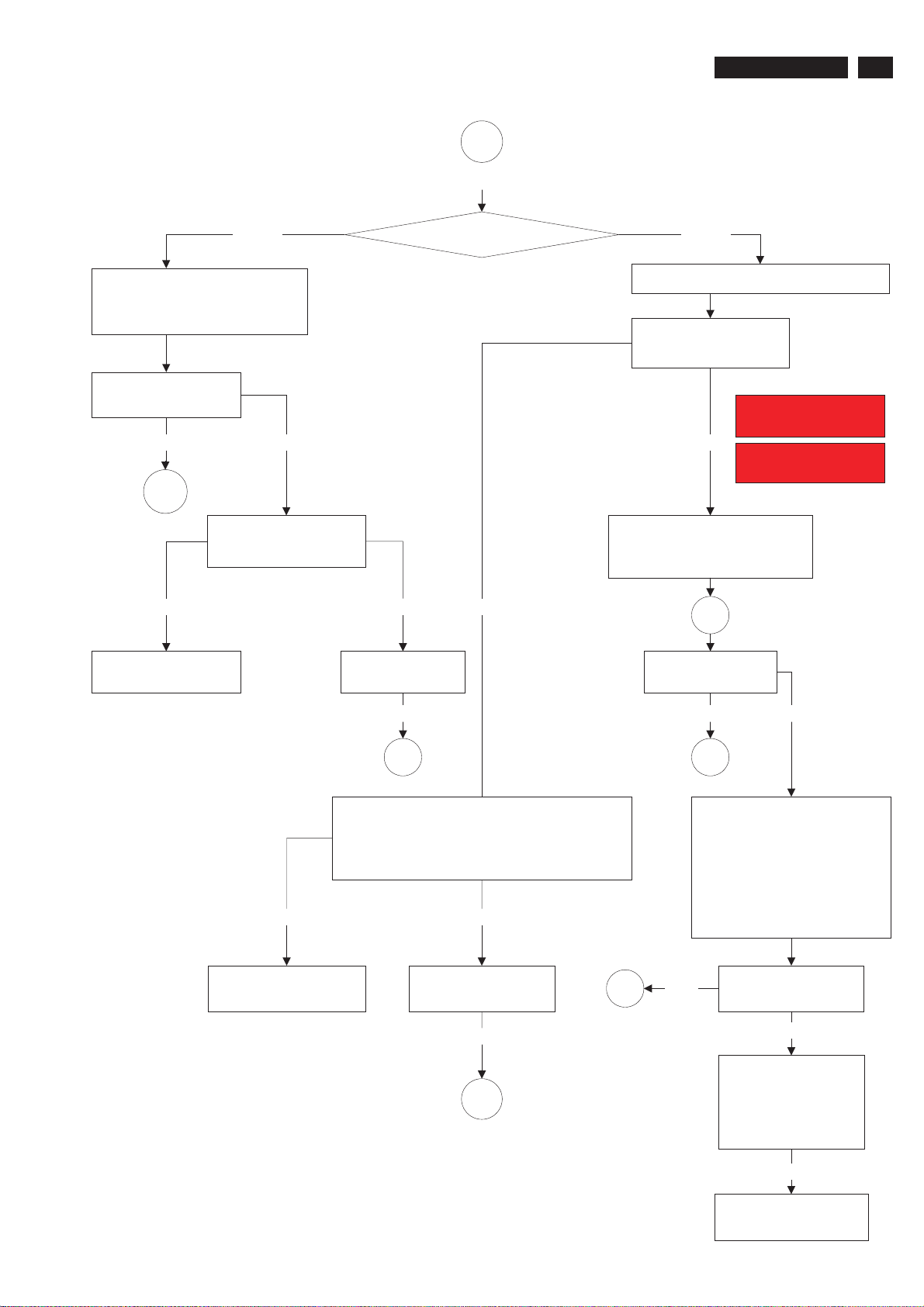
General Trouble Shooting Guide
1
Continued
220VW8 LCD
45
Amber
Make sure of the state of the
computer (turn on). Press the
keyboard or operate the mouse.
Is picture display
normally?
YES
END
Power off the monitor
and then restart PC
No Yes Yes
It is need to check
and repair the monitor
No
LED Amber or Green?
Is picture display
normally?
Green
Make sure the correct signal is input.
Is the ATTENTION
picture displayed?
For example:
ATTENTION
CHECK SIGNAL CABLE
No
ATTENTION
NO SIGNAL INPUT
Check contrast level is not
minimized. (Press contrast
button, increase v alue to 100)
OK
Is picture displayed
normally?
Yes Yes No
END
1. Make sure the correct signal is input.
2. Press the keyboard or operate the mouse.
3. Make sure of the range of the input
frequency and then set the computer.
YesNo
END
1. Check video cable for bent
pins, reseat it.
2. Change resolution (It may
cause by PC.)
3. LCD monitor can not
display Vertical Frequency
settingat76Hz&85Hz
http://www.wjel.net
It is need to check and
repair the monitor
Is picture displayed
normally?
Yes
END
END
Yes
Is picture displayed
normally?
No
1. Try system with
another monitor.
2. Try monitor with
another system.
unsuccessful
It is need to check and
repair the monitor.
Page 46
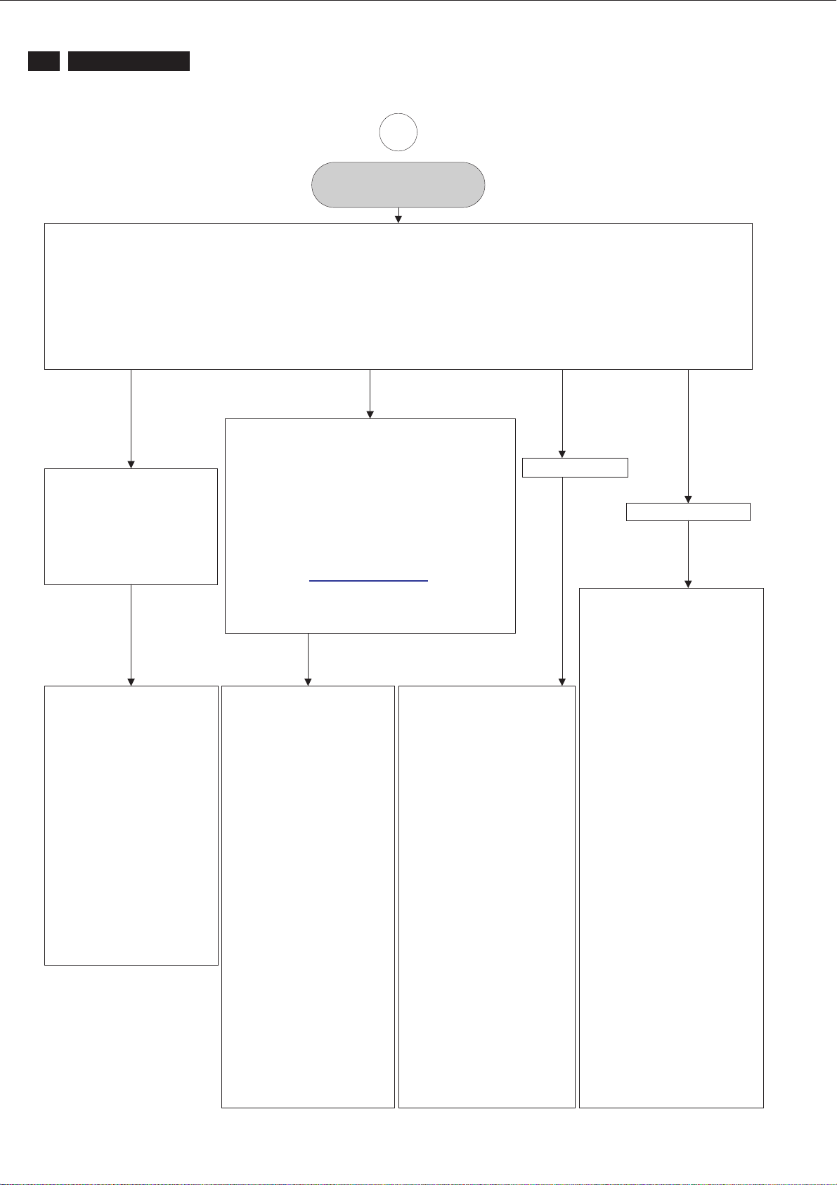
46
220VW8 LCD
General Trouble Shooting Guide
2
Monitor drivers (inf file)
FOR WINDOWS 95/98/2000/ME OR LATER
Philips’s monitors build in VESA DDC2B feature to support Plug & Play requirement for Windows 95/98/2000/Me. You can install the
information file(.inf) in order to select your Philips monitor from “Monitor” dialog box in Windows 95/98/2000/Me to activate Plug &
Play application. The installation procedure based on Windows 95 OEM Release 2, 98, Me and 2000 is specified as follows, (in case
of connecting the monitor to the PC compliant with VESA standard with the designated signal cable, the PC reads display pixels,
frequency and color feature of this monitor to optimize the picture for the monitor automatically.)
DDC: Abbreviation for Display Data Channel
** Windows NT 4.0 does not require driver (inf file) for monitor.**
For Windows 98
For Windows 98 drivers, our monitors are listed under
For Windows 95
For Windows 95 drivers, your
monitor is listed under
manufacture name “Philips
Business Electronics Co.”.
1. Start Windows 95
2. Click the ‘Start’ button,
point to ‘setting’, and
then click ‘control panel’.
3. Double click the
‘display’ lcon.
4. Choose the ‘setting’ tab then
click ‘advanced…’
5. Choose ‘monitor’ button,
point to ‘change…’ then click
‘have disk…’.
6. Click ‘browse…’ button then
choose the appropriate drive
F:(CD-ROM Drive) then click
‘ok’ button.
7. Click the ‘ok’ button then
choose your monitor model
and click the ‘ok’.
8. Click ‘close’ button.
2 manufactures name “Philips”, and “Philips
Consumer Electronics Co.” Please select “Philips”
when you would like to set up your monitor in
Windows setting, if you can not find the right model
name just as the label indication on the back of set.
For those set that have been issued since the release
of Window 98, drivers can be found in CD-ROM
under the directory path of “\pc\driver\” or it may be
downloaded at http://www.philips.com
have installed the new driver, Windows will add a
new manufacture name “Philips Business
Electronics” in your system.
1. Start Windows 98
2. Click the ‘Start’ button, point
to ‘setting’, and then clock
‘control panel’.
3. Double click the
‘display’ lcon.
4. Choose the ‘setting’ tab then
click ‘advanced…’
5. Choose ‘monitor’ button,
point to ‘change…’
then click ‘next’.
6. Choose ‘display a list of all
http://www.wjel.net
the drivers in a specify
location, so you can select
the driver you want’, then
click ‘next’ and then click
‘have disk…’
7. Click ‘browse…’ button then
choose the appropriate drive
F: (RD-ROM Drive)
then click ‘ok” button.
8. Click the ‘ok’ button then
choose your monitor model
and click the ‘next’ button.
9. Click ‘finish’ button then click
‘close’ button.
. Once you
1. Start Window Me
2. Click the ‘start’ button, point
to ‘setting’ , and then click
‘control panel’.
3. Double click the
‘display’ lcon.
4. Choose the ‘setting’ tab then
click ‘advanced…’.
5. Choose ‘monitor’ button, then
click ‘change…’ button.
6. Choose ‘specify the location
of the driver (advanced)’ and
click the ‘next’ button.
7. Choose ‘display a list of all
the drivers in a specific
location, so you can select
the driver you want’, then
click ‘next’ and then click
‘have disk…’.
8. Click ‘browse…’ button then
choose the appropriate drive
F: (CD-ROM Drive)
then click ‘ok’ button.
9. Click the ‘ok’ button then
choose your monitor model
and click the ‘next’ button.
10. Click ‘finish’ button then
click ‘close’ button.
For Window Me
For Windows 2000
1. Start Windows 2000
2. Click the ‘start’ button, point
to ‘setting’, and then click
‘control panel’.
3. Double click the
‘display’ lcon.
4. Choose the ‘setting’ tab then
click ‘advanced…’.
5. Choose ‘monitor;
- If the ‘properties’ button is
inactive, it means your
monitor is properly configured.
Please stop installation.
- If the ‘properties’ button is
active, click ‘properties’ button.
6. Click ‘driver’ and then click on
‘update driver…’ then click on
the ‘next’ button.
7. Choose ‘display a list of the
known drivers for this device
so that I can choose a specific
driver’ then click ‘next’ and
then click ‘have disk…’.
8. Click ‘browse…’ button then
choose the appropriate drive
F: (CD-ROM Drive).
9. Click the ‘open’ button then
click the ‘ok’ button.
10. Choose your monitor model
and click the ‘next’ button.
11. Click ‘finish’ button and then
click the ‘close’ button. If you
can see the ‘digital signature
not found’ window then click
the ‘yes’ button.
Page 47
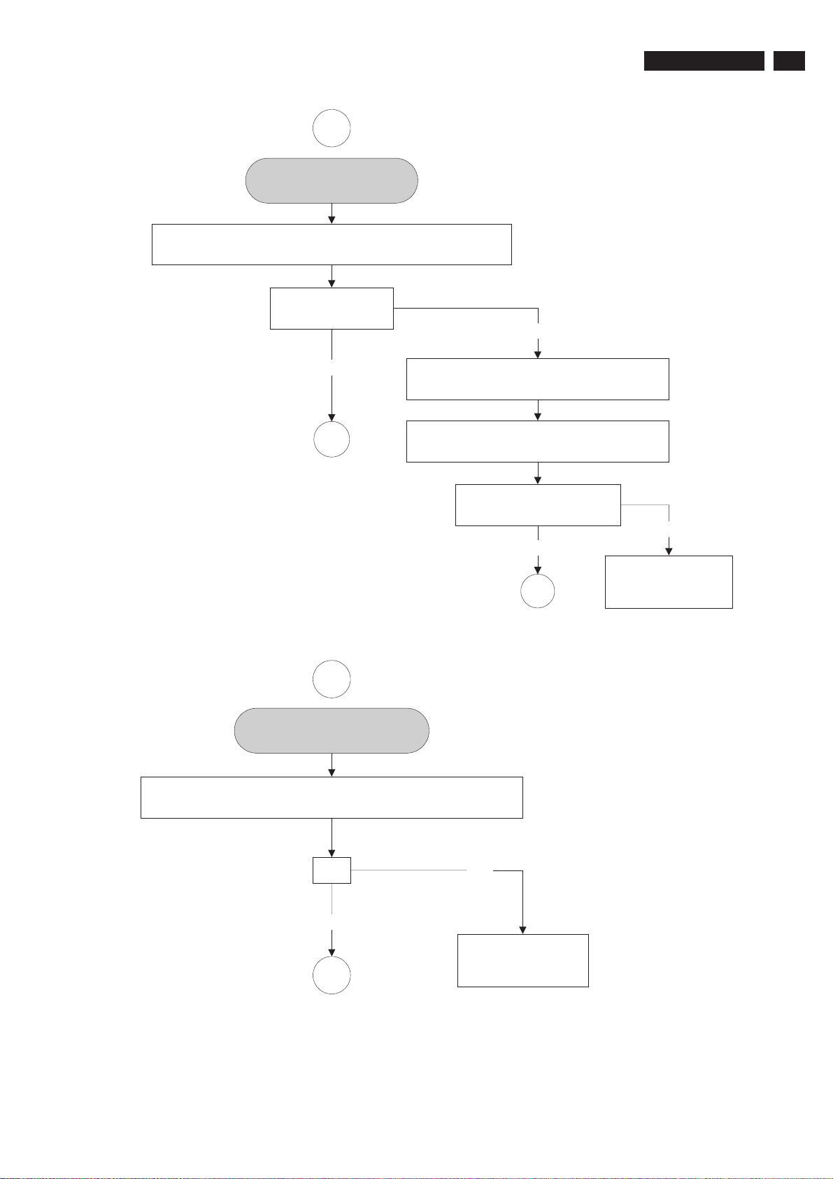
General Trouble Shooting Guide
3
Screen Size Not Correct
Adjust Horizontal/Vertical/Shape Via the monitor "On Screen
Display" or "Front Control Knob: Auto function key"
Is the Screen Size
displayed correct?
.
No
220VW8 LCD
47
YES
END
4
Picture is too large or small
*Reset the monitor via OSD manipulation
(Select Reset to Factory settings).
* Try the monitor with another computer
(Video card could be defective.)
Is picture displayed
normally?
YES
Consult a service
END
center, the monitor
may be defective.
No
Reset monitor via OSD menu manipulation.
Change monitor timing to work at the recommended resolution.
http://www.wjel.net
OK
YES
END
NO
Please contact your
dealer/reseller for
more information.
Page 48
48
220VW8 LCD
General Trouble Shooting Guide
6
Unstable picture/picture
flickers
Vertical/Horizontal flicker appears,
Push the AUTO button. Eliminate the Vertical/Horizontal bars
using the Phase Adjustment in the first window.
OK
YES NO
END
Please contact your
dealer/reseller for
more information.
http://www.wjel.net
Page 49
General Trouble Shooting Guide
7
Out of H/V Sync.
1. Turn off monitor
2. Disconnect signal cable
3. Turn on monitor
220VW8 LCD
49
In the self test?
(warning signal¡K)
YES
It is need to check and
repair the monitor
NO
Check video cable for bent
pins, reseat to system
video and power system.
Trytogointothe
DOS prompt.
"H/V sync. Out of
presetting timing range"
or "Sync. Problem"?
YES
1. Try system with
another monitor
2. Try monitor with
another system
Make sure that the video
system doesn't select a
driver that is outside the
NO
monitor H/V scan range out
of presetting timing range
while going into windows.
Run windows by using
basic VGA mode
(example 640*480)
"H/V sync. Out of
Monitor related?
YES
It is need to check and
http://www.wjel.net
repair the monitor
NO
Video system problem
END
presetting timing range"
or "Sync. Problem"?
YES
1. Try system with
another monitor
2. Try monitor with
another system
Monitor related?
YES
It is need to check and
repair the monitor
NO
END
Page 50
50
220VW8 LCD
Picture is too bright
Adjust brightness and/or contrast via
the monitor "On Screen Display"
or "Front Control Knob"
General Trouble Shooting Guide
8
Is picture displayed
normally?
YES
END
NO
* Reset the monitor via OSD manipulation.
(Select Reset to factory settings¡ )
* (or change the color temperature settings
to be 9300 color coordination from OSD menu.
* Try the monitor with another computer
(video card could be defective.)
Is picture displayed
normally?
YES NO
END
It is need to check and
repair the monitor
http://www.wjel.net
Page 51
General Trouble Shooting Guide
9
Picture is too dim
220VW8 LCD
51
Adjust brightness and/or contrast
via the monitor "On Screen Display"
or "Front Control Knob".
Is picture displayed
normally?
YES
Is an external Anti-Glare screen
(like protective cover, touch
END
Note:
1. Sun light passing through a window is much brighter than monitor
luminance (luminance is the measurable quantity which most closely
corresponds to brightness), therefore the two worst places for a
monitor is directly facing the window or directly behind the window.
Position the monitor away from these two areas.
screen...etc) being used?
Remove any external
Anti-Glare screen
Is picture displayed
normally?
YES
NO
* Reset the monitor via OSD manipulation.
(select Reset to factory settings)
NO
* (or change the color temperature settings to
be 9300 color coordination from OSD menu)
* Try the monitor with another computer
(video card could be defective)
Is picture displayed
normally?
YES NO
END
END
It is need to
check and repair
the monitor
http://www.wjel.net
Page 52
52
220VW8 LCD
1. Is the correct AC power
cord connected?
2. Is AC power outlet active?
3. Is the power button in the
ON position?
YES
General Trouble Shooting Guide
10
NOPOWER/LEDisoff
Is cabinet of
NO YES
monitor damaged
by being dropped?
The monitor may have
become faulty due to
excessive shock
Power off the monitor
and then on
YES
Power LED on ?
YES
END
http://www.wjel.net
NO
It is need to check and
repair the monitor
Insure that unit is plugged into a
known good power source
(move a good radio to plug into
the power source to test it)
YES
Power LED on ?
YES
END
It is need to check
and repair the monitor
NO
Page 53
General Trouble Shooting Guide
11
Missing Color
220VW8 LCD
53
1. Turn off monitor
2. Disconnect video cable
3. Turn on monitor
Colors on warning
signal OK?
YES
Check video cable for bent
pins, reseat it
Signal cable pins OK?
YES
1. Try system with
another monitor.
2. Try monitor with
another system.
3. Try changing in
the application.
There are 2 easy ways to determine the Missing color problem.
1. View an image that is supposed to be
If one of the colors (RGB) is not functioning.
White can not be produced.
2. View an image that supposed to contain Red, Green and Blue.
Color problems will be apparent when one or more of these
colors can not be displayed.
Normal White:
RED
Cyan Color means that the red sub pixel is missing.
RED
Magenta or Purple Color means that the green sub pixel is missing.
RED
Yellow Color means that the blue sub pixel is missing.
RED
GREEN
+
GREEN
+
GREEN
+
GREEN
+
+
+
+
+
"White".
BLUE
BLUE
BLUE
BLUE
=
=
=
=
WHITE
Cyan
Magenta
Yellow
Is picture displayed
normally?
YES
END
It is need to check and
http://www.wjel.net
NO
repair the monitor.
Page 54
54
220VW8 LCD
General Trouble Shooting Guide
12
OSD MAIN MENU LOCKED
Press and hold the OSD menu key for about 10 seconds,
until picture displays "OSD MAIN MENU UNLOCKED".
OK
YES
END
NO
Please contact your
dealer/reseller for
more information
http://www.wjel.net
Page 55
General Trouble Shooting Guide
12
OSD MAIN MENU LOCKED
Press and hold the OSD menu key for about 10 seconds,
until picture displays "OSD MAIN MENU UNLOCKED".
OK
220VW8 LCD
55
YES
END
NO
Please contact your
dealer/reseller for
more information
http://www.wjel.net
Page 56
56
220VW8 LCD
display or image for 30
Jitter or Noise still present?
NO
Try moving the monitor to
another location to see if
END
General Trouble Shooting Guide
13
Jitter / Video Noise
Turn on monitor with a
minutes (due to drift).
YES
problem goes away
Jitter or Noise disappear
YES
Environment problem
END
NO
1. Try system with
another monitor
2. Try monitor with
another system
Jitter or Noise disappear
YES
Video system problem
END
NO
Monitor related?
Power off any monitor that
is within 2 or 3 feet away
Remove any unshielded
speakers away from the
monitor
Make sure there are no
flourescent light fixtures
close to the monitor
http://www.wjel.net
NO
It is need to check and
repair the monitor
Try to keep monitor away from
large metal structures, power
poles, fans and metal carts
Check for other devices
that may be causing
magnetic interference
Is picture displayed
normally?
YES
END
Page 57
General Trouble Shooting Guide
14
Power management
function is not active
Verify the PC is compliant with VESA. In case all of the
video signals of PC are not off, power management
function is not active normally. (Repeat to power on and
off power management.) There are accelerator boards
not complied with VESA.
OK
220VW8 LCD
57
YES
END
NO
Consult a service
center, the monitor
may be defective
http://www.wjel.net
Page 58

58 220VW8 LCD
General Product Specification
Specification for TVI WBZR-V1C
Philips Hudson 8 – 220VW8
22’’W TFT LCD Monitor,
30 - 93 KHz, 56 - 76 Hz, Dual input
Table of Contents
1. PRODUCT SPECIFICATION
1.1 Relationship
1.2 Product Data
2. MECHANICAL SPECIFICATION
2.1.1 Monitor Housing
2.1.2 VESA mounting holes
2.1.3 Kensington Slot
2.2 Tilt / Swivel base of the monitor
2.3 Dimensions of monitor
2.4 Dimensions of pallet and quantity
3. LCD SPECIFICATION
3.1 LCD specification
4. COSMETICS APPEARANCE
4.1 GAP definition
4.2 Panel Offset
4.3 Horizontal tilt
5. CONNECTORS
5.1 Video Connection
5.2 PIN Assignment
5.2.1 15 pin mini D-Sub connector
6. OSD
6.1 Control of OSD
6.2 Adjustment Parameters
7. ELECTRICAL SPECIFICATION
7.1 Power Specification
7.1.1 AC-DC converter
7.1.2 Power Management
7.2 Standard Test conditions
7.3 Test equipment
7.4 Video Generator test sequence
7.5 Analog input
7.6 Optical response time
7.7 Protection circuit
7.8 DDC
7.8.1 DDC Details
7.9 Timings
7.10 Audio Specification
http://www.wjel.net
Page 59

8. DISPLAY PERFORMANCE
8.1 Picture performance
8.2 Geometric defects
8.3 Picture stability during war m up
8.4 Scratches
8.5 Viewing angle
8.6 Jitter
8.7 Missing Pixels / missing subpixel
8.8 Newton Ring
8.9 Luminance Output
8.9.1 Luminance Output
8.9.2 Brightness
8.9.3 Brightness Uniformity
8.10 White Uniformity
8.11 Contrast ratio
8.12 White color adjustment
8.13 Distance between TFT LCD monitor and CRT/TFT monitor
9. ENVIRONMENT
9.1 Environmental conditions
10. REGULATORY STANDARDS
10.1 Safety approvals
10.2 Power management
10.3 Certificates, Reports for the production start
11. RELIABILITY
11.1 Reliability of the monitor
12. CUSTOMIZATION
12.1 Identity Customization
12.2 EAN /SAP Identification
12.3 Plastic
12.4 Definition of serial number
12.5 Definition of the barcode label
12.6 Accessories
13. ECR-HANDLING
59 220VW8 LCD
http://www.wjel.net
Page 60
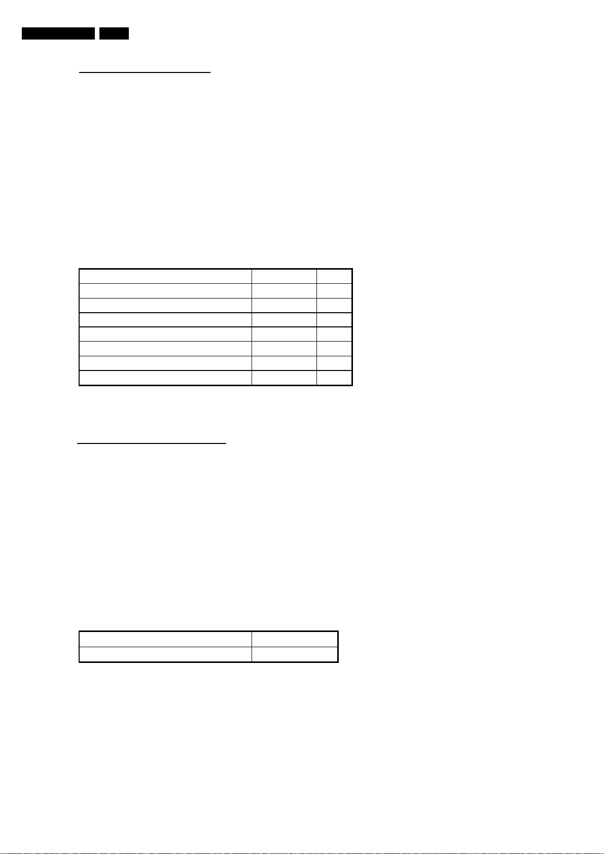
60 220VW8 LCD
1. PRODUCT SPECIFICATION
1.1 Relationship
Supplier: TVI Model: WBZR-V1C
Customer: Philips Model: Hudson 8 -220VW8
• Monitor No: HWS8220Q
• Monitor ID:
•
220VW8FB/00
220VW8FB/93
220VW8FB/96
Site Code: CJ (TVE); CU (QCG)
1.2 Product Data
22’’W TFT LCD monitor
Horizontal frequency 30 - 93 KHz
Vertical frequency 56 - 76 Hz
Screen diagonal 22 Inch
Viewing Angle(CR>10) (H/V) 160/160 °
Max. opening horizontal picture size 477.7 mm
Max. opening vertical picture size 300.1 mm
Max. active horizontal picture size 473.76 mm
Max. active vertical picture size 296.1 mm
2. MECHANICAL SPECIFICATION
2.1.1 Monitor Housing
The front bezel and the back cabinet are based on TVI OEM tooling and Philips design chin.
2.1.2 Vesa mounting holes
According to Vesa FPMPMI standard.
Holes 100 mm x 100 mm (M 4.0, 0.7 pitch threaded) in the rear center for ARM.
2.1.3 Kensington Slot
The monitor is equipped with a 7 mm x 3 mm slot.
2.2 Tilt of the monitor
Forward
Backward
2.3 Dimensions of monitor
The monitor has the following dimensions:
Unit dimension : 513.8mm (W) * 416.2mm (H) * 213.6mm (D)
Packed unit dimension: 565.0mm (W) * 174.0mm (H) * 472.0 mm (D) for WW
Net weight : 5 Kg (Including I/F cable 240 g)
Gross weight : 5.6 Kg for WW
http://www.wjel.net
-5 ° +2/- 0
+25 °+0/- 3 °
: 567.0mm (W) * 189.0mm (H) * 480.0 mm (D) for China
: 5.6 Kg for China
Page 61
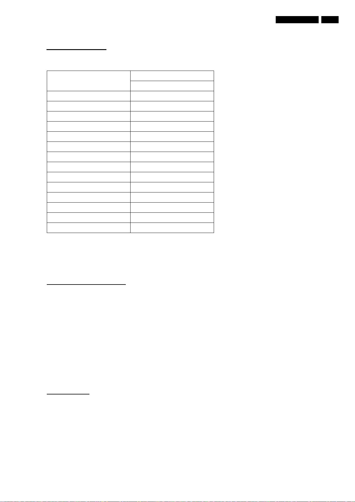
3. LCD SPECIFICATION
3.1 LCD specification
Panel
Resolution 1680x 1050
Active area (HxV) 494.94 x 290.5875
Outside dimensions(WxHxD) 493.7 x 320.1 x 16.5
Pitch (mm) 0.27675 x 0.27675
Display surface Non-glare type
Color depth 16.7M colors
Backlight 4 CCFL
Viewing angle 170:H/ 160:V
Contrast ratio 1000:1 (Typ); 700:1 (Min)
White luminance 300nit (Typ); 200nit (Min)
Color gamut 72%
61 220VW8 LCD
CPT
CLAA 220WA01
Gate IC TBC
Source IC TBC
Response time 5ms
4 COSMETICS APPEARANCE
4.1 GAP definition
The gap between LCD and front bezel must be <= 1.2m m
4.2 Panel Offset
Panel Offset: Panel disposition tolerance inside the front bezel must be <=1.0mm
4.3 Horizontal tilt
Horizontal tilt between front bezel & LCD shall be <= 1.0mm
5. CONNECTORS
5.1 Video Connection
The monitor is equipped with a 15 pin mini D-SUB connector.
5.2 PIN Assignment
5.2.1 15 pin mini D-Sub connector
The PIN assignment of the 15 pin mini D-SUB connector / cable is as follows:
http://www.wjel.net
Page 62
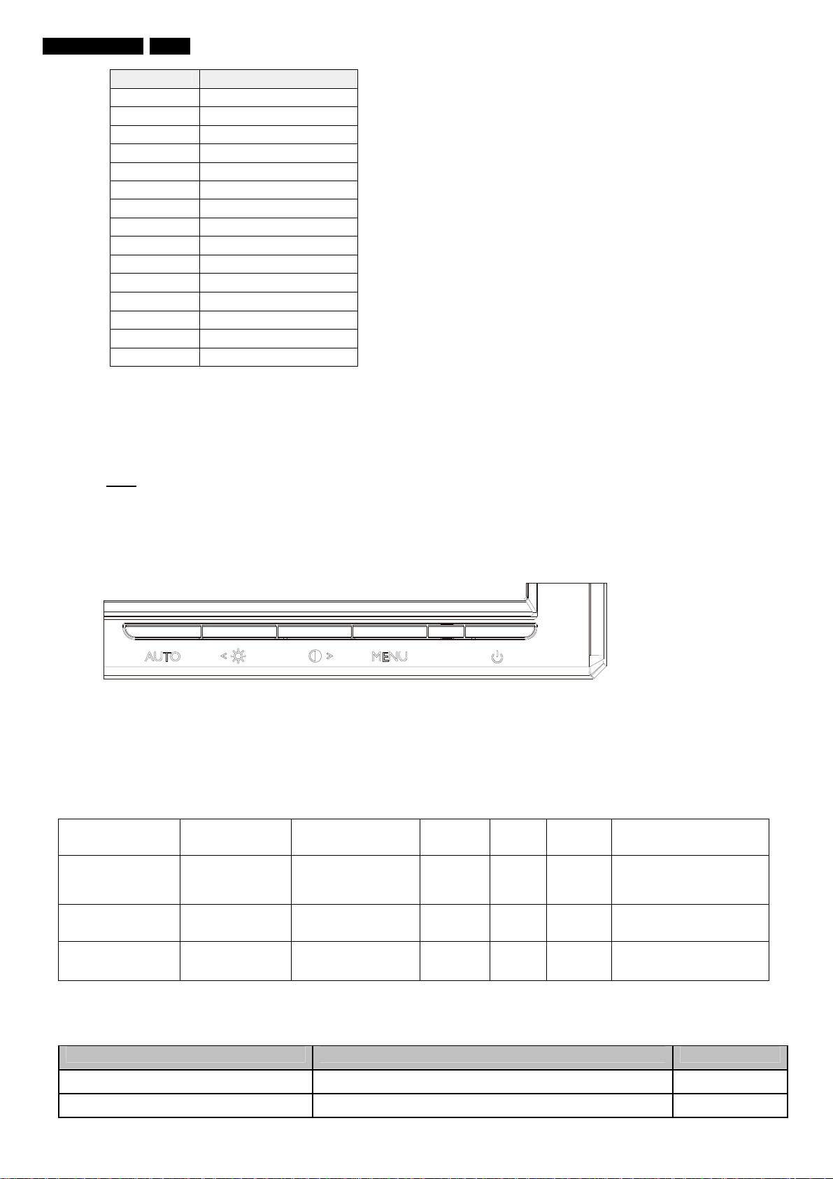
62 220VW8 LCD
PIN No. SIGNAL
1 Red
2 Green/ SOG
3 Blue
4 Sense (GND)
5 N/A
6 Red GND
7 Green GND
8 Blue GND
9 DDC +3.3V or +5V
10 Logic GND
11 Sense (GND)
12 Bi-directional data
13 H/H+V sync
14 V-sync
15 Data clock
6. OSD
6.1 Control of OSD
The positions and functions of the buttons are defined as below.
6.2 Adjustment Parameters
Hot-key definition
Monitor Controls
Lock MENU/OK
Factory Mode
DDC/CI On/OFF
for VISTA
OSD Tree
MONITOR SETUP
Exit
Key Key Press Time
http://www.wjel.net
6 sec
(lock/unlock) 3 sec V V
AUTO+MENU+
Power On
UP+DOWN
1st LEVEL 2nd LEVEL 3rd LEVEL
Keep pressing
when power on V
6 sec
(lock/unlock)
OSD
Timeout EDFU
3 sec V V DDC/CI ON/OFF
Service
menu OSD Message
MONITOR
CONTROLS LOCKED
/UNLOCKED
Page 63
63 220VW8 LCD
Brightness & Contrast
Color Original Color, 9300K,6500K, sRGB, User Define
Input Selection Analog(D-Sub)
More Settings
Audio Option Stand-alone
(For selective model) Mute
Volume
Serial No.:
(Serial No.)
Timing Mode
Up/Down to Move, ok to Confirm
7. ELECTRICAL SPECIFICATION
7.1 Power Specification
7.1.1 AC-DC converter
Input voltage 90- 264 V
Frequency range 50/ 60 ± 2 Hz
Inrush current Shall be less than the ratings of critical components
(including fuse, rectifiers and surge limiting device)
for all conditions of line in voltage.
Maximum power
consumption: <50W maximum, <45W ( typ.)
7.1.2 Power Management
Mode HSYNC VSYNC Video Pwr-cons. Indication Rec. time
Power-On On On active < 50W(<54W: for audio model) Green LED --
Off Off Off blanked < 1 W Amber LED < 3 s
DC Power Off N/A < 1 W LED Off
http://www.wjel.net
Brightness
Contrast
Horizontal Position
Vertical
Language See SKU
Phase/ Clock
OSD Settings
No Reset
Yes
Phase
Clock
Horizontal
Vertical
7.2 Standard Test conditions
Unless otherwise specified, this specification is defined under the following conditions.
(1) Input signal : As defined in Timing table, 1680 x 1050
non-interlaced mode (1680X1050@60Hz 146.25MHz), signal
sources must have 75 ohm output impedance.
Page 64
64 220VW8 LCD
(2) Luminance setting : controls to be set to 300 nits with
full screen 100 % duty cycle white signal
(3) Warm up: more than 30 minutes after power on with signal supplied.
(4) Ambient light: 400 – 600 lux.
(5) Ambient temperature: 20 ± 5 °C
7.3 Test equipment
Personal computer with Windows 98/2000/XP
Luminance meter Minolta CA110
Videogenerator: Chroma 2000, 2135, 2250 or equivalent
Colour analyzer: Minolta or Chroma
10 times magnifier
Ruler / Template
Thickness gauge
Watt / Power Meter
7.4 Video Generator test sequence
Will be defined by TVI or its subcontracted quality providers.
7.5 Analog input
Analog input R,G,B level: 0 - 850 mV max.
Polarity: positive, negative
Impedance: 75 Ω ± 1%
Sync: HV separate sync, composite sync,
7.6 Optical response time
Video Bandwidth: 165 MHz (dot rate)
Typical rise time(CMO) 5 ms
7.7 Protection circuit
The monitor will not be damaged by:
missing vertical or horizontal sync pulse
improper vertical or horizontal sync pulse (picture must be black at improper signals,
unsynchronized pictures are not allowed
7.8 DDC
The monitor can support DDC 2 B and DDC-CI according to the latest VESA standard.
7.8.1 DDC Details
1 User visible strings on .inf file Philips 220VW (22’’ LCD MONITOR 220VW8)
2 Manufacturer ID ( EDID data) PHL
3 Product ID, "xxxx" 4 codes
4 maximum resolution 1680x1050
5 Horizontal Frequency Range 30~93 KHz
6 Vertical Frequency Range 56~76Hz
7 Monitor Name (13 characteries max.) Philips 220VW
7.9 Timings
http://www.wjel.net
)
MSB(byte 12): 08
LSB (byte 11): 51
Page 65
Factory preset modes : 18
Preset modes : 45
User modes : 10
Note: 1. Screen displays perfect picture at 18 factory-preset modes.
2. Screen displays visible picture with OSD warning when input modes are the 45 preset modes.
Factory preset modes (18 modes)
Item H.Freq. (KHz) Mode Resolution V.Freq. (Hz) BW(MHz)
1 31.469 IBM VGA 10H 640x350 70.086
2 31.469 IBM VGA 3H 720x400 70.087
3 31.469 IBM VGA 12H 640x480 59.94
4 35 MACINTOSH 640x480 67
5 37.861 VESA 640x480 72.809
6 37.5 VESA 640x480 75
7 43.269 VESA 640x480 85.008
8 35.156 VESA 800x600 56.25
65 220VW8 LCD
9 37.879 VESA 800x600 60.317
10 48.077 VESA 800x600 72.188
11 46.875 VESA 800x600 75
12 53.674 VESA 800x600 85.061
13 49.7 MACINTOSH 832x624 75
14 56.4 - 960x720 75
15 44.75 - 960x720 60
16 48.363 VESA 1024x768 60.004
17 56.476 VESA 1024x768 70.069
18 60.023 VESA 1024x768 75.029
19 61.08 IBM XGA-2 1024x768 75.781
20 68.677 VESA 1024x768 84.997
21 CVT 2.3MA 1280 x768 60
22 60.289 CVT 2.3MA 1280 x768 75
23 54.1 1152x864 60
24 63.851 VESA 1152x864 70.012
http://www.wjel.net
25 67.5 VESA 1152x864 75
26 68.7 MACINTOSH 1152x870 75
27 61.845 SUN WS 1152x900 66.004
28 71.81 SUN WS 1152x900 76.15
29 60 VESA 1280x960 60
30 75 VESA 1280x960 75
31 63.981 VESA 1280x1024 60.02
32 71.691 SUN WS 1280x1024 67.189
33 76 DOS/V 1280x1024 72
Page 66
66 200AW8 LCD
34 79.976 VESA 1280x1024 75.025
35 81.13 SUN WS 1280x1024 76.11
36 91.1 VESA 1280x1024 85
37 44.772 - 1280x720 60
38 52.5 - 1280x720 70
39 55.469 VESA-reduced blanking
mode
40 55.935 VESA 1440x900 59.887 106.5
41 70.635 VESA 1440x900 74.984 136.75
42 75 VESA 1600x1200 60 161
43 66.587 CVT 2.3MA-R 1920x1080 60.0 138.5
44 65.29 CVT1.76MW 1680x1050 60 146
45 65.29 CVT1.76MW-R 1680x1050 60 119
1440x900 59.901 88.75
Remark: Timing which marked light-blue are factory preset mode.
7.10 Audio Specification
N/A
8. DISPLAY PERFORMANCE
8.1 Picture performance
Optical performance test must be done in a dark room.
Note: Test under standard test conditions unless otherwise specified
Active Image Size (all modes)
8.2 Geometric defects
No vertical or/and horizontal line defect.
No cross line defect.
8.3 Picture stability during warm up
During 10 - 30 minutes warm up time from cold condition of the monitor
at ambient temperature (25°C ± 5°C) the decrease of brightness must be less than 6 Fl.
8.4 Scratches
No scratches and foreign particles visible.
http://www.wjel.net
8.5 Viewing angle
Typical(10:1)
Horizental (Right + Left) 160°
Vertical (Up + Down) 160°
8.6 Jitter
No jitter visible in each condition. In case of problem a limit sample has to be defined.
8.7 Missing Pixels / missing subpixel
Page 67
67 220VW8 LCD
BRIGHT DOT DEFECTS ACCEPTABLE LEVEL
MODEL
1 lit sub-pixel 3
2 adjacent lit sub-pixels 1
3 adjacent lit sub-pixels (one white pixel) 0
Distance between two bright dots 15mm
Bright dot defects within 20 mm circle 0
Total bright dot defects of all type 3
220VW8
BLACK DOT DEFECTS ACCEPTABLE LEVEL
MODEL
1 dark sub-pixel 5
2 adjacent dark sub-pixels 2
3 adjacent dark sub-pixels (one white pixel) 1
Distance between two black dots 15mm
Black dot defects within 20 mm circle* 1
Total black dot defects of all type 5
220VW8
TOTAL DOT DEFECTS ACCEPTABLE LEVEL
MODEL
Total bright or black dot defects of all type 5
220VW8
8.8 Newton Ring
No Newton Rings visible.
8.9 Luminance Output
8.9.1 Luminance Output
Test resolution: 1680 x 1050 at 60 Hz
Test condition: video input (RGB) = maximum white
8.9.2 Brightness
To follow Panel specification. sRGB = 80 ± 10 nits.
8.9.3 Brightness uniformity
Set contrast at 100% and turn the brightness to get average above 300 nits at centre of the screen.
Apply the Fig 1, it should comply with the following formula:
B_min
X 100%
B_max
Where B_max = Maximum brightness
B_min = Minimum brightness
8.10 White Uniformity
http://www.wjel.net
Definition of White Variation (δW):
Page 68
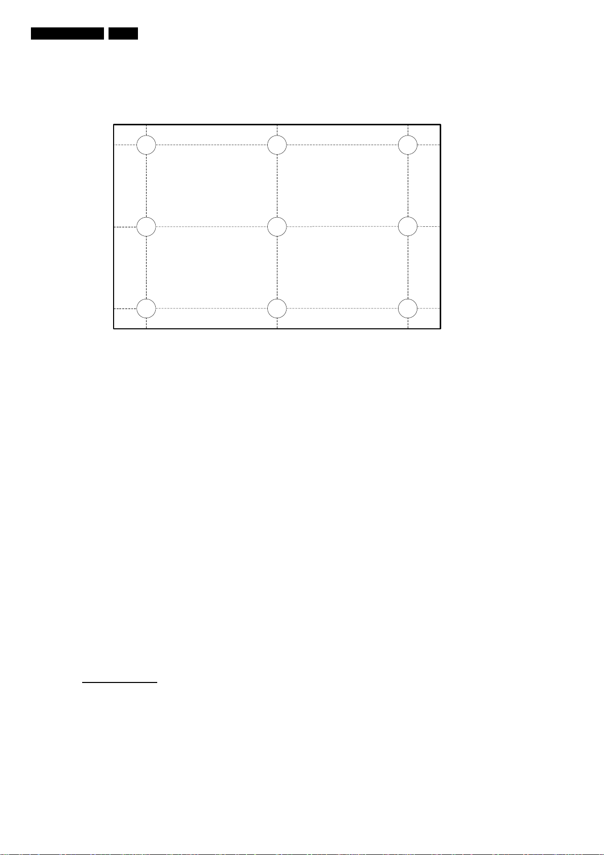
68 220VW8 LCD
9
2
4 5
6
7 8
1 3
10%
50%
90%
10%
50%
90%
Measure the luminance of gray level 255 at 9 points
δW = Maximum [L(1), L(2) …… L(9)] / Minimum [L(1), L(2) …… L(9)]
8.11 Contrast ratio
The contrast ration can be calculated by following expression.
Contrast Ratio (CR) = L255 / L0
L255 : Luminance of gray level 255
L0 : Luminance of gray level 0
Typical value: 1000:1
8.12 White color adjustment
Apply full gray64 pattern, with brightness in 100 % position and the contrast control at 50 % position.
8.13 Distance between TFT LCD monitor and CRT/TFT monitor
Conducted with different modes or frequencies. No interference in a distance down to 25 cm.
9. ENVIRONMENT
9.1 Environmental conditions
Product spec.
9300K CIE coordinates X = 0.283 ± 0.02
Y = 0.297 ± 0.02
6500K/ sRGB CIE coordinates X = 0.313 ± 0.02
Y = 0.329 ± 0.02
Y = 0.329 ± 0.02
There are three factory preset white color 9300K, 6500K, sRGB.
The 1931 CIE Chromaticity (color triangle) diagram (x,y) coordinate for the screen center should be:
sRGB CIE coordinates X = 0.313 ± 0.02
http://www.wjel.net
Page 69

Production alignment spec.
9300K CIE coordinates X = 0.283 ± 0.005
Y = 0.297 ± 0.005
6500K/ sRGB CIE coordinates X = 0.313 ± 0.005
Y = 0.329 ± 0.005
sRGB CIE coordinates X = 0.313 ± 0.005
Y = 0.329 ± 0.005
Quality Inspection spec.
9300K CIE coordinates X = 0.283 ± 0.015
Y = 0.297 ± 0.015
6500K/ sRGB CIE coordinates X = 0.313 ± 0.015
Y = 0.329 ± 0.015
sRGB CIE coordinates X = 0.313 ± 0.015
Y = 0.329 ± 0.015
10. REGULATORY STANDARDS
Note: All certificates must be raised under the name of Philips
10.1 Safety approvals
; CB report
; CE
; TUV GS
; TCO’0
10.2 Power management
; Ener gy Star
10.3 Certificates, Reports for the production start
When the first production of the monitor starts the following documents must be sent to Philips by mail. All
reports must be raised under “Philips” and have to show WBZR model name .
;CB report
;CE
;FCC
;Service manual
11 RELIABILITY
11.1 Reliability of the monitor
The MTBF of the monitor has to be greater than 50.000 hours. The MTBF shall be calculated according to
the MIL Standard HBDK 217 E/F. The report about the calculation detail shall be provided on component
level before mass- production by TVI. The calculation shall be performed for a primary test/preset mode
under ambient temperature of 25°C.
12. CUSTOMIZATION
12.1 Identity Customization
Refer to SKU
http://www.wjel.net
69 220VW8 LCD
Page 70

70 220VW8 LCD
12.2 EAN /SAP Identification
Refer to SKU
12.3 Plastic
The plastic material of the monitor must be PC-ABS (Front/ back) ABS-HB (base).
Plastic type and color is released as follows:
Refer to MakeUp sheet/ Graphic sheet
12.4 Definition of serialnumber
Refer to Philips’ definition
12.5 Definition of the barcode label
Refer to Philips’ definition
12.6 Accessories
Refer to SKU
13. ECR-HANDLING
Not any change without approved ECR.
Every ECR to the golden “ samples” must be approved by PHILIPS, Even ECR for minor changes must be
released by PHILIPS.
For the ECR procedure the vendor has to send an ECR formular, necessary spec updates, datasheets and
a photo documentation. On based on documents, PHILIPS has to decide if samples are necessary till
release to changes. The vendor also has to proof be certificates and test reports, that the change has no
effect on safety, EMI and TCO03.
After testing, PHILIPS has to release or reject the change request.
http://www.wjel.net
Page 71
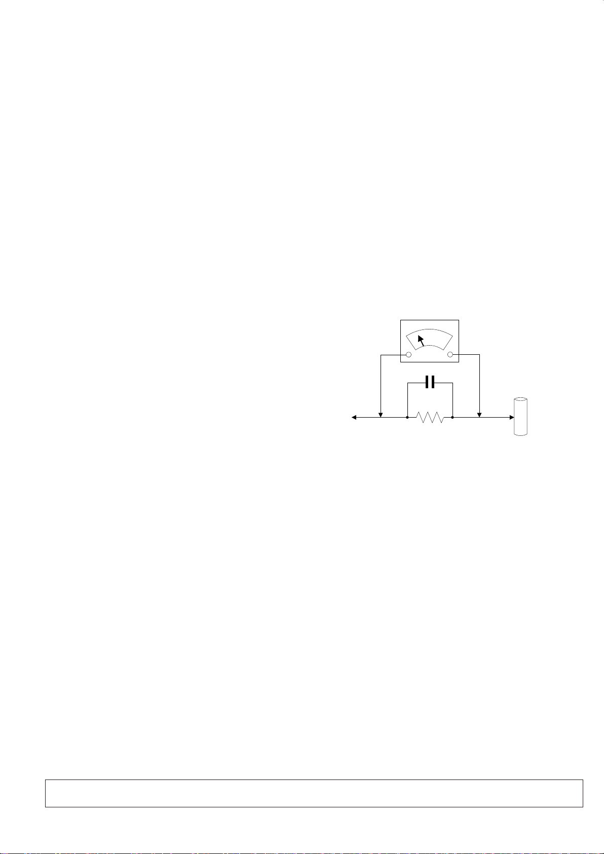
Safety Check Process
To
INSTRUMENTS
EXPOSED
METAL PARTS
1500 ohm, 10W
0.15uF
WATER
PIPE
EARTH
GROUND
Safety Check s
After the orig inal service problem has been correcte d, a complete safety check
should be made . Be sure to check over the entire set, not just t he areas where
you have worke d. Some previous service may have left an un safe condition,
which could be u nknowingly passed on to your customer. Be su re to check all
of the followi ng:
Fire and Shock H azard
1. Be sure all com ponents are positioned in such a way as to avo id the
possibilit y of adjacent component shorts. This is especially important on those
chassis whic h are transported to and form the service sh op.
2. Never relea se a repaired unit unless all protective d evices such as
insulators , barries, covers, strain reliefs, and o ther hardware have been
installed in a ccordance with the original design.
3. Soldering a nd wiring must be inspected to locate poss ible cold solder joints,
solder splas hes, sharp solder points, frayed leads , pinched leads, or damaged
insulation (including the accord). Be certain to re move loose solder balls and all
other loose fo reign particles.
4. Check acros s-the-line components and other comp onents for physical
evidence of da mage or deteriortion and replace if nece ssary. Follow original
layout, lead l ength and dress.
5. No lead or comp onent should touch a receiving tube or a res istor rated at
1watt or more. L ead tension around protruding metal su rfaces or edges must
be avoided.
6. Critical co mponents having special safety chara cteristics are identified with
ans bythe Ref. No in the parts list and enclosed within a bro ken line *( Where
several crit ical components are grouped in one area) a long with the safety
symbols on the s chematic diagrams and/or exploded vi ews.
7.When servi cing any unit, always use a separate isola tion transformer for the
chassis fail ure to use a separate isolation transfor mer may expose you to
possible sho ck hazard, and may cause damage to servici ng instruments.
8. Many electr onic products use a polarized ac line cord (one wide pin on the
plug). Defea ting this safety feature may create a pote ntial hazard to the
service and th e user. Extension cords which do not incorpo rate the polarizing
feature shou ld never be used.
9. After reassem bly of the unit, always perform an leakage t est or resistance
test from the li ne cord to all exposed metal parts of the cabi nets. Also check all
metal contro l shafts(with knobs removed), antenn a terminals, handles, screws,
etc. To be sure t he unit may be safety operated without dan ger of electrical
shock.
* Broken line
Implosion
1. All picture tub es used in current model receivers are equ ipped with an
intergral im plosion system care should always be use d, and safety glasses
worn, whenev er handling any picture tube. Avoid s cratching or other wise
damaging the p icture tube during installation.
2. Use only repl acement tubes specified by the manufac turer.
X-radiatio n
1. Be sure proce dures and instructions to all your servi ce personal cover the
subject of X-r adiation. Potential sources of X-ray s in TV receivers ar e the
picture tube a nd the high voltage circuits. The b asic precaution which must be
exercised is t o keep the high voltage at the factory recom mended level.
2. To avoid pos sible exposure to X-radiation and elec trical shock, only the
manufactur er’s specified anode c onnectors must be used.
3. It is essenti al that the service technician has an accu rate HV meter available
at all times. The calibration of this meter shoul d be checked periodically against
a reference st andard.
4. When the HV cir cuitry isoperating properly there is n o possibility of an Xradiation pr oblem. High voltage should always be kep t at the manufacture,
rated value- no higher- for optimum performance. Ev ery time a color set is
serviced, th e brightness should be run up and while moni toring the HV with a
meter to be cert ain that the HV is requation correctly and d oes not exceed the
specified va lue. We suggest that you and your tec hnicians review test
procedures s o that HV requation are always checked as a st andard servicing
procedure, a nd the reason for this prudent routine is cl eanly understood by
everyone. It i s important ot use an accurate and reliabl e HV meter. It is
recommende d that the HV recorded on each customer’s invoice, which will
demonstrat e a proper concern for the customer’s safety.
5. When troubl eshooting and making test measuremen ts in a receiver with a
problem of exc essive high voltage, reduce the line vol tage by means of a variac
to bring the HV in to acceptable limits while troublesh ooting. Do not operate the
chassis lone r than necessary to locate the cause of the ex cessive HV.
http://www.wjel.net
6. New picture t ubes are specifically designed to with stand higher operating
voltages wit hout creating undesirable X-radiat ion. It is strongly recommended
that any shop te st fixture which is to be used with the new high er voltage
chassis be equ ipped with one of the new type tubes designe d for this service.
Addition of a pe rmanently connected HV meter to the shop t est fixture is
advisable. The CRT types used in th ese new sets should never be replaced
with any other t ypes, as this may result in excessive X-ra diation.
7. It is essenti al to use the specified picture tube to avoi d a possible X-radiation
problem.
8. Most TV receivers contain come types of emerge ncy” Hold Down” circuit to
prevent HV fro m rising to excessive levels in the presen ce of a failure mode.
These variou s circuits should be understood by all tec hnicians servicing them,
especially s ince many hold down circuits are inopera tive as long as the
receiver per forms normally.
Leakage Curr ent Cold Check
1. Unplug the ac l ine cord and connect a jumper between the tw o prongs of the
plug.
2. Turn on the power s witch.
3. Measure the r esistance value between the jumpered a c plug and all exposed
cabinet part s of the receiver, such as screw heads, antenn as, and control
shafts. When t he exposed metallic part has a return path t o the chassis, the
reading shou ld be between 1 meg ohm and 5.2 megohms. When t he exposed
metal does not h ave a return path to the chassis, the readin g must be infinity.
Remove the jum per from the ac line cord.
Leakage Curr ent Hot Check
1. Do not use an iso lation transformer for this test. Plug t he completely
reassemble d receiver directly into the ac outlet.
2. Connect a 1.5 k, 10w resistor paralleled by a 0.15uf cap acitor between each
exposed meta llic cabinet part and a good earth ground su ch as a water pipe, as
shown above.
3. Use an ac voltm eter with at least 5000 ohms volt sensitiv ity to measure the
potential ac ross the resistor.
4. The po tential at any point should not exceed 0.7 5 volts. A leakage current
tester may be us ed to make this test; leakage current must n ot exceed a
possibilit y of shock hazard. The receiver sho uld be repaired and rechecked
before retur ning it to the customer.
5. Repeat the ab ove procedure with the ac plug reversed. (note: an ac adapter
is necessary w hen a polarized plug is used. Do not defeat th e polarizing
feature of the p lug.)
Picture Tube Replacement
The primary so urce of X-radiation in this television r eceiver is the picture tube.
The picture tu be utilized in this chassis is specially c onstructed to limit Xradiation em issions. For continued X-radiation p rotection, the replacement
tube must be the s ame types as the original, including suff ix letter, or a Philips
approved tub e.
Parts Replac ement
Many electri cal and mechanical parts in Philips tele vision sets have special
safety relat ed characteristics. These cha racteristics are ofte n not evident from
visual inspe ction nor can the protection affo rded by them necessarily be
obtained by us ing replacement components r=ated fo r higher voltage, wattage,
etc. Th e use of a substitute part which does not have t he same safety
characteri stics as the Philips recommended repla cement part should in this
service manu al may create shock, fire, or other hazard s.
WARNING: Before removing the back cover, turn the unit OFF and short the HIGH VOLTAGE to the ground.
 Loading...