

Page 1

1
DFU 20FT3010/37 050404.0944 PRELIMINARY
P
20” LCD Monitor with iFace
and Philips ITV SmartPort
for health care applications
Institutional Television
www.itv.philips.com
PRELIMINARY
Pillow speaker /
pendant control
(not included)
(rear view of unit)
Philips SmartPlug
TM
Pillow speaker /
pendant control
interface
Directions For Use
20FT3010/37
20FT3010/37
lmtb
Page 2
2
DFU 20FT3010/37 050404.0944 PRELIMINARY
1. Read these instructions.
2. Keep these instructions.
3. Heed all warnings.
4. Follow all instructions.
5. Do not use this apparatus near water.
6. Clean only with a dry cloth.
7. Do not block any of the ventilation openings. Install in accordance
with the manufacturers instructions.
8. Do not install near any heat sources such as radiators, heat registers,
stoves, or other apparatus (including amplifiers) that produce heat.
9. Do not defeat the safety purpose of the polarized or grounding type
plug. A polarized plug has two blades with one wider than the other.
A grounding type plug has two blades and third grounding prong. The
wide blade or third prong are provided for your safety. When the provided plug does not fit into your outlet, consult an electrician for
replacement of the obsolete outlet.
10. Protect the power cord from being walked on or pinched particularly
at plugs, convenience receptacles, and the point where they exit from
the apparatus.
11. Only use attachments/accessories specified by the manufacturer.
Use only with a cart, stand, tripod, bracket, or table specified by the manufacturer, or sold with the apparatus. When
a cart is used, use caution when moving the cart/apparatus
combination to avoid injury from tip-over.
13. Unplug this apparatus during lightning storms or when unused for
long periods of time.
14. Refer all servicing to qualified service personnel. Servicing is
required when the apparatus has been damaged in any way, such as
power-supply cord or plug is damaged, liquid has been spilled or
objects have fallen into apparatus, the apparatus has been exposed to
rain or moisture, does not operate normally, or has been dropped.
15. This product may contain lead and mercury. Disposal of these materials may be regulated due to environmental considerations. For disposal or recycling information, please contact your local authorities or the
Electronic Industries Alliance: www.eiae.org
16. Damage Requiring Service - The appliance should be serviced by
qualified service personnel when:
A. The power supply cord or the plug has been damaged; or
B. Objects have fallen, or liquid has been spilled into the appliance;
or
C. The appliance has been exposed to rain; or
D. The appliance does not appear to operate normally or exhibits a
marked change in performance; or
E. The appliance has been dropped, or the enclosure damaged.
17. Tilt/Stability - All televisions must comply with recommended international global safety standards for tilt and stability properties of its
cabinet design.
· Do not compromise these design standards by applying excessive
pull force to the front, or top, of the cabinet which could ultimately
overturn the product.
· Also, do not endanger yourself, or children, by placing electronic
equipment/toys on the top of the cabinet. Such items could unsuspectingly fall from the top of the set and cause product damage and/or personal injury.
18. Wall or Ceiling Mounting - The appliance should be mounted to a wall
or ceiling only as recommended by the manufacturer.
19. Power Lines - An outdoor antenna should be located away from power
lines.
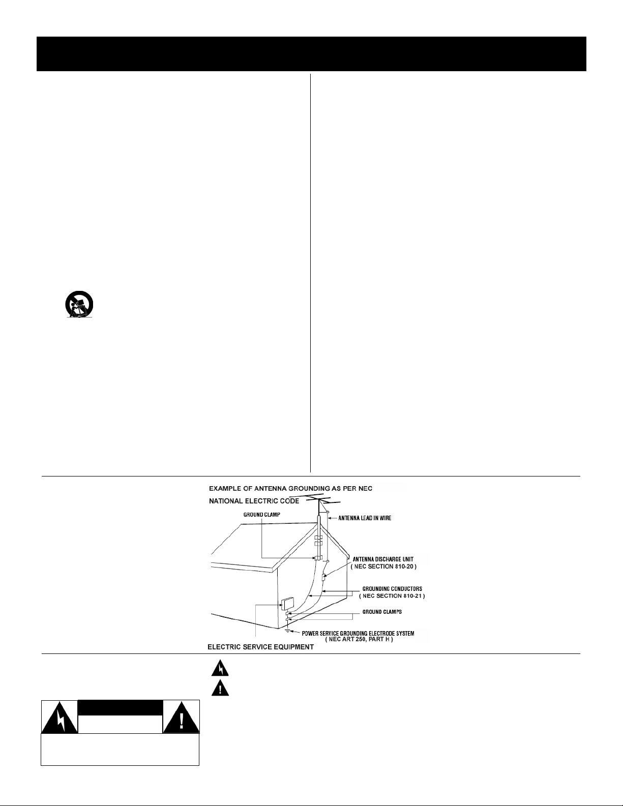
20. Outdoor Antenna Grounding - If an outside antenna is connected to
the receiver, be sure the antenna system is grounded so as to provide
some protection against voltage surges and built up static charges.
Section 810 of the National Electric Code, ANSI/NFPA No. 70-1984,
provides information with respect to proper grounding of the mast and
supporting structure, grounding of the lead-in wire to an antenna discharge unit, size of grounding connectors, location of antenna-discharge unit, connection to grounding electrodes, and requirements for
the grounding electrode. See Figure below.
21. Object and Liquid Entry - Care should be taken so that objects do not
fall and liquids are not spilled into the enclosure through openings.
22. Battery Usage CAUTION - To prevent battery leakage that may result
in bodily injury, property damage, or damage to the unit:
· Install all batteries correctly, with + and - aligned as marked on the
unit
· Do not mix batteries (old and new or carbon and alkaline, etc.)
· Remove batteries when the unit is not used for a long time.
Know these
safety symbols
C A U T I O N
RISK OF ELECTRIC SHOCK
DO NOT OPEN
CAUTION: TO REDUCE THE RISK OF ELECTRIC
SHOCK, DO NOT REMOVE COVER (OR BACK). NO
USER SERVICEABLE PARTS INSIDE. REFER SERVICING TO QUALIFIED SERVICE PERSONNEL.
This “bolt of lightning” indicates uninsulated material within your unit which may cause an electrical shock.
For the safety of everyone in your household, please do not remove product covering.
The “exclamation point” calls attention to features for which you should read the enclosed literature closely to
prevent operating and maintenance problems.
WARNING: To reduce the risk of fire or electric shock, this appliance should not be exposed to rain or moisture and objects filled with liquids, such as vases, should not be placed on this apparatus.
CAUTION: To prevent electric shock, match wide blade of plug to wide slot, and fully insert.
ATTENTION: Pour éviter les chocs électriques, introduire la lame la plus large de la fiche dans la bome correspondante de la prise et pousser jusqu’au fond.
12.
Note to the CATV system installer: This reminder is provided to call the
CATV system installer's attention to Article 820-40 of the NEC that provides
guidelines for proper grounding and, in particular, specifies that the cable
ground shall be connected to the grounding system of the building, as
close to the point of cable entry as practical.
IMPORTANT SAFETY INSTRUCTIONS
Read before operating equipment
Page 3

3
DFU 20FT3010/37 050404.0944 PRELIMINARY
A/V Audio / video.
CVBS
Composite Video Blanking Sync. Also known as "composite" or "AUX" video. In this method of video connection, the color, luminance and synchronization signals are combined on one wire.
DCM
Data Communications Module. General term for devices that communicate with Philips Institutional Television
products by means of the Philips ITV SmartPort.
DFU Directions For Use. User documentation. Also (formerly) known as “IB”, “Instruction Booklet”.
Display Monitor In this documentation, the non-Iconnized television display monitor itself.
FTV Flat television (plasma or LCD television display monitor).
hciFace, hiFace® Hospital version(s) of iFace.
H-M Link®
Hotel-mode link. Control interface based on a subset of Philips SmartPort, for hospitality in-room television
applications.
iFace®
Infra-red interface. Internally-installed ITV intelligent interface module that adds Philips SmartPort connectivity
to display products that do not have built-in SmartPort.
irFace® Alternate name for iFace.
IR
Infra-red, long-wavelength optical energy invisible to the human eye. In this document, denotes wireless
remote controls. In some contexts, can also refer to wired (non-optical) un-modulated TTL RC signals.
ITV
Institutional Television. Commercial / non-consumer business unit of Philips Consumer Electronics Co., a division of Koninklijke Philips Electronics N.V., its products, and its intellectual property.
Jack A receptacle connector that typically resides on a panel built into an electrical or electronic device.
LCD
Liquid-crystal display. An image-display technology that achieves a thin panel form factor and low power consumption.
NA, N/A Not available, not applicable.
NC, N/C Not connected, no connection.
Off See "Standby".
On
A state of operation in which the unit (television) is connected to an AC power source, in active use, and capable of responding to queries or commands from a control device (IR remote control) and/or DCM.
OSD
On-Screen Display. Text characters that are generated by the display monitor’s or set-top box’s character generator. Used to display menus, status, closed-captioning, channel, etc.
Plug Connector, usually on a cable, that connects to a socket receptacle connector.
RC Remote control. Also see IR.
RC-5, RC-6 Philips IR remote control communication protocols.
RJ-11 / RJ-12 Registered Jack 11 / 12. Modular telephone-style connector with 4 / 6 electrical conductors.
SmartPort® Philips ITV proprietary three-wire synchronous serial communications and control interface. AKA SmartPlug.
Socket Receptacle connector on a cable or jack panel that connects to a plug.
Standby
Typically referred to as "off". A state of operation, characterized by relatively low power consumption, in which
the unit (television) is connected to an AC power source, but not in active use, and capable of responding to
queries or commands from a local keypad (if enabled), a control device and/or a DCM.
S-Video
Super-Video, sometimes referred to as Y/C Video, is a video signal connection method in which the luminance
(Y) signal and chrominance (C) signal are conveyed on separate signal paths in order to achieve picture quality that is significantly improved over CVBS (see CVBS).
TTL
Transistor-Transistor Logic, a common semiconductor technology. Also denotes the signal voltages corresponding to digital information (“0” or “1”), such as that in wired remote-control commands.
YPbPr
Component video, a video signal connection method in which the luminance (Y) signal, the Pb (blue), and Pr
(red) signals are conveyed on separate signal paths. Sync and green signal components are present on Y.
Glossary
Page 4
The 20FT3010/37 is a specialized television product configuration consisting of a Philips 20” LCD television / monitor
(20PF7835) equipped with an intelligent interface board (iFace) that adds Philips ITV SmartPort compatibility.
hiFace makes it possible to offer a cost-effective LCD television display solution for use with Philips ITV-compatible
SmartPort data communication modules (DCM) for hospitality / pay-per-view, health-care, audio/visual, and other
non-consumer applications.
Important Product Application and Warranty Information
The 20FT3010/37 is neither marketed, sold, nor intended for consumer applications. The 20FT3010/37 is neither marketed, sold, nor intended to be considered, neither expressly or by implication, as capable of being converted or re-configured for consumer applications. The warranty does not apply to, and is void for, units that have been altered, converted, re-configured, or modified in any way without prior written authorization from Philips Institutional Television.
4
DFU 20FT3010/37 050404.0944 PRELIMINARY
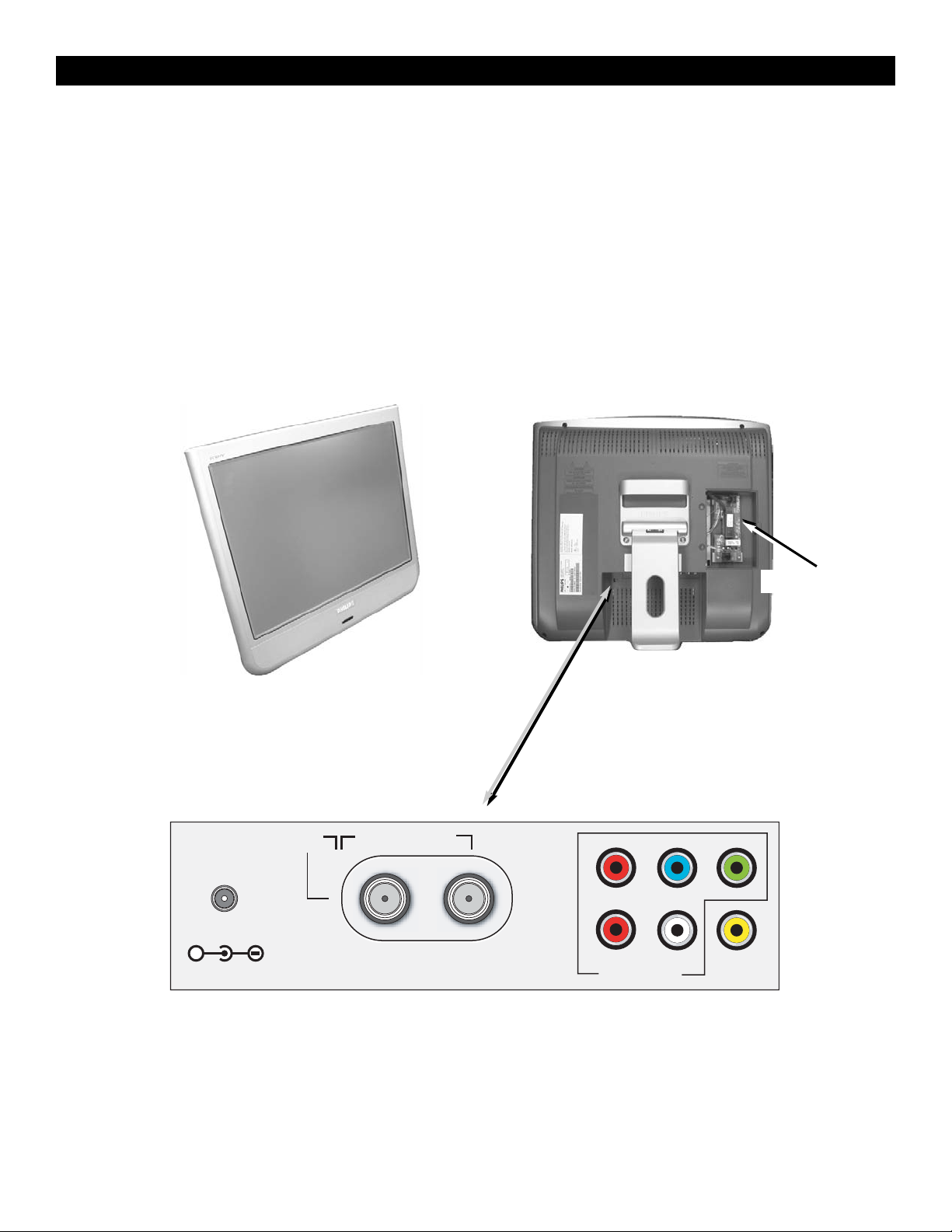
Product Description
20FT3010/37
Front view
Rear view
(IFACE / HIFACE cover removed)
hiFace board
LCD monitor A/V jack panel
DC in
+
Ω
75
FM ANT
COMP
VIDEO
INPUT
AV1
IN
PbPr
RL
Audio in Video in
Y
Page 5
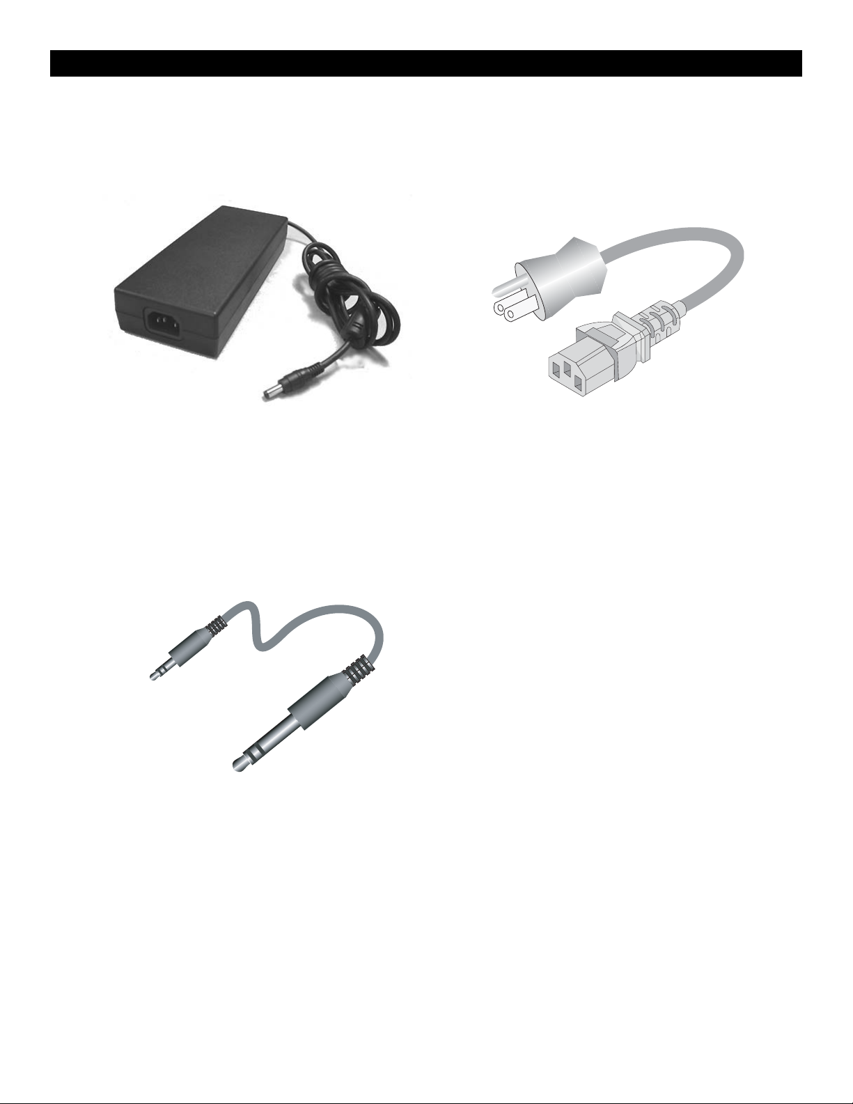
Included Accessories
The 20FT3010/37 includes the following accessories:
5
DFU 20FT3010/37 050404.0944 PRELIMINARY
Power adapter cable
AC mains, 6 ft
Hospital grade 3-prong plug, IEC socket
Certification(s): CSA33169CLASS584103
CSA33169CLASS584202
ULE55349SPV1
Product Accessories
Power adapter
Input: 100-240 VAC, 50/60 Hz; IEC connector
Output: 24 VDC @ 5A, coaxial plug
Agencies: UL, CE, NOM
Pillow Speaker / Pendant Extension Cable
1/8” mini stereo phone plug to 1/4” stereo
phone plug, 3-ft, 3-conductor cable (adapts
IFACE / HIFACE 1/8” mini stereo phone jack
to pillow speaker
Page 6
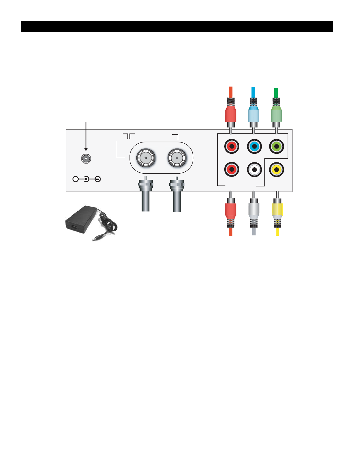
The 20FT3010/37 connects to the AC mains and audio / video signal sources as shown.
6
DFU 20FT3010/37 050404.0944 PRELIMINARY
20FT3010/37 A/V Jack Panel Connection Information
LCD monitor jack panel (A / V)
1. AC mains adapter 24 volts DC, center- (+) positive.
2. RF television signal.
3. FM radio signal.
4. Right audio channel from CVBS or component (“YPbPr”) video source.
5. Left audio channel from CVBS or component (“YPbPr”) video source.
6. CVBS video.
7. Y (luminance, green, and sync) of YPbPr component video.
8. Pb (blue) component pf YPbPr component video.
9. Pr (red) component pf YPbPr component video.
78 9
1
FM ANT
COMP
VIDEO
INPUT
AV1
IN
23
PbPr
RL
Audio in Video in
456
DC in
+
75
Ω
1
Y
Page 7

The following diagram illustrates the connections to the iFace / hiFace module.
7
DFU 20FT3010/37 050404.0944 PRELIMINARY
20FT3010/37 iFace / hiFace Connection Information
1/4" PHONE
PLUG
IFACE INTERFACE BOARD
(20FT3010 INTERNAL)
HEALTH-CARE FACILITY
WIRING INFRASTRUCTURE
(1/4" PHONE JACKS)
LCD MONITOR
INTERNAL SPEAKER
DISCONNECT SWITCH
SMART PLUG
RJ-12 JACK
SMART LOADER CABLE
PHILIPS CLON99BK
SMART LOADER
(OPTIONAL ITV ACCESSORY)
3-FT ADAPTER
CABLE
(SUPPLIED)
1/8" MINI
PHONE PLUG
1/8" MINI PHONE JACK
(PILLOW SPEAKER /
PENDANT INTERFACE)
1/4" PHONE
PLUG
PILLOW SPEAKER /
PENDANT CONTROL
(OPTIONAL THIRD-PARTY
ACCESSORY)
Page 8

Philips Institutional TV Software
Typical Philips Institutional Televisions can be configured to operate in either "Consumer" or "Commercial" operational
modes. However, the 20FT3010/37 hiFace-based ITV product is primarily intended to operate in the Commercial mode.
Consumer-mode operation is not intended for the 20FT3010/37, because it is based on a consumer product (20PF7835)
that is adapted for commercial use by means of the hiFace module.
Commercial Mode
The configuration of Commercial mode features requires a Philips ITV master setup remote (RG4172BK or RC2573GR,
optional accessory). When the television is in Commercial mode, access to its operation from its keyboard or from a
guest-mode remote can be restricted, depending upon the settings of the Institutional TV features. For examples, the
unit’s keyboard controls can be “locked-out” (rendered inoperable), only certain channels can be selected, and the volume can be limited to a given range.
Identifying the Operational Mode: To identify the television’s operational mode, a system 7 (commercial setup mode)
master setup remote must be used. With the setup remote in setup mode (RG4172BK: press TV SETUP, or RC2573:
place switch in SETUP position), press Recall. The following information will appear on-screen, depending upon the
version of iFace / HcIface.
N
OTE: There are currently two versions of the 20FT3010/37. The respective versions are as indicated in the last line of
the respective SYSTEM STATUS.
8
DFU 20FT3010/37 050404.0944 PRELIMINARY
Philips ITV General Information
MODE COMMERCIAL
CHANNEL TV 12 (ANTENNA)
DCM OFF
CODES 96 1 98 48 8
0 200 32 32 34
SIGNAL TUNED
OP HRS 000Bh
IFACE 1.01
SYSTEM STATUS
RG4172BK RC2573GR
Philips ITV master setup remotes
MODE COMMERCIAL
CHANNEL AV2 (AV2)
DCM OFF
CODES 44 0 34 48 8
0 200 32 32 32
OP HRS 000Bh
HCIFACE 0.07 / 1.00
IFACE 1.01 HCIFACE 0.07 / 1.00
Page 9

You can access the Philips ITV TV Setup Menu using the “M” key on a Philips ITV master setup remote control that is
in setup mode. The following setup menus are available on the 20FT3010/37. Please note that these menus are generated by hiFace / iFace module, not by the LCD television monitor. The factory default settings are shown. For detailed
descriptions of the setup menu items, please refer to the section
HIFACE / ITV SETUP MENU ITEM DESCRIPTIONS.
NOTE: There are currently two versions of the 20FT3010/37, depending upon the version of the resident HCIFACE /
IFACE module. The menus of the respective versions differ as indicated below. The versions are distinguishable as
described in the earlier section I
DENTIFYING THE
OPERATIONAL MODE. Functional differences in the setup menu are noted
in the section entitled IFACE* / HIFACE* ITV SETUP MENU I
TEM DESCRIPTIONS.
Note: AV1YC / AV2 / AV2YC appear in the menu, but are not applicable to the 20FT3010/37
* HIFACE: SERIAL NUMBER DK1A
IFACE: SERIAL NUMBER DK1B
9
DFU 20FT3010/37 050404.0944 PRELIMINARY
Philips ITV Setup Menu
MENU ITEM
IFACE
1.01
HCIFace
0.07 /
1.00
SETTINGS / OPTIONS DEFAULT SETTING
LANGUAGE
9 9
ENGLISH / ESPANOL / FRANÇAIS ENGLISH
CHANNEL INSTALL
9 9
> CHANNEL INSTALL
CURRENT RING
9 9
> CHANNELS 2 -13
SWITCH ON CHANNEL
9 9
STANDARD / AV1 / AV1YC / AV2 / AV2YC / CVI / TV 1-125 STANDARD
POWER ON
9 9
STANDARD / FORCED STANDARD
CHANNEL DISPLAY
9 8
NUMBER / LABEL / ALL / NONE ALL
KEYBOARD LOCK
9 9
ON / OFF OFF
ESP
9 9
1-99 / OFF OFF
WELCOME MESSAGE
9 8
> OFF
CHANNEL GUIDE
9 9
POWER ON / OFF / ON OFF
REMINDER
9 8
ON / OFF OFF
3 DIGIT ENTRY
9 9
ON / OFF OFF
A/CH A/V SWITCH
9 8
ON / OFF OFF
AV LOCK
8 9
ON / OFF OFF
IFACE CONTROL
9 8
ON / OFF ON
SECURITY
9 9
STANDARD / HIGH STANDARD
EXIT >
TV SETUP MENU
20FT3010/37 setup menu
Page 10

LANGUAGE SETUP x CONSUMER x FEATURES MENU_
An on-screen LANGUAGE option is available. You can set the TV's on-screen menu to appear in English, French, or
Spanish text. With the Main Menu on-screen. press the Menu button repeatedly, or use the Cursor Up and Down buttons, to select LANGUAGE with the TV’s highlight control bar. Press Cursor Right (+>) or Left (<- ) on the remote to
select English, French (FRANCAIS), or Spanish (ESPANOL). Text in the on-screen Menu will appear in the selected
language.
________________________________________________________________________________________________
CHANNEL
INSTALL
SETUP x
CONSUMER x FEATURES MENU_
When C
HANNEL INSTALL is highlighted, use Channel Up/Down, or enter the desired channel number using the Number buttons
you wish to edit. The following control items, contained within the Channel Installation menu, will affect the chosen channel.
CHANNEL
- When CHANNEL is selected, use Channel Up/Down, or enter the desired channel number using the Number but-
tons.
*NOT AVAILABLE ON HCIFACE 0.07 / HIFACE 1.0
Note: Inputs in italics appear in the menu, but are not implemented.
· AV1 refers to the CVBS input on the 20FT3010 jack panel.
· AV1YC, AV2, and AV2YC appear in the menu but are not implemented.
· A “channel” can be either an RF channel (1-125) or a video input (AV1, CVI). RF channels (1 - 125) can select ANTENNA (normal mode), or be re-directed to (i.e. used to select) a video input. In other words, Channel 3 could select AV1,
Channel 4 could select CVI, etc. This re-direction is sometimes referred to as channel mapping. However, video inputs
can select only a video input (AV1 / CVI). Video inputs cannot be mapped to ANTENNA.
· Note: The screen will blank momentarily, and there will be a short delay, when you step through the C
HANNEL and
I
NPUT
selections.
CHANNEL RING 1-4 C
HANNEL RING determines the channels or inputs that are accessible by means of the television’s key-
board (if it is not locked out) or from a guest-mode remote control. When CHANNEL RING 1, 2, 3, or 4 is highlighted, press
the Cursor Right (+>) or Left (<- ) buttons on the remote to choose SAVED or DELETED. When SAVED is selected, the
channel will remain in, or be added to, the respective channel ring. When DELETED is selected, the channel will be removed
from the respective channel ring and will not appear when TV channels are scanned (using the Channel +,- buttons). Each of
the four channel rings can be programmed individually, but only one channel ring can be in effect at any given time. The channel ring that is currently in effect is specified in the setup menu C
URRENT RING item (see CURRENT RING).
INPUT - When INPUT is highlighted, press the Cursor Right (+>) or Left (<- ) buttons on the remote to select ANTENNA,
FRONT, AUX, S-VIDEO input signal options. I
NPUT directs the TV to select the specific indicated input whenever this chan-
nel is tuned. See CHANNEL, above.
LABEL - When L
ABEL is highlighted, press the Cursor Right (+>) button on the remote to select the first character space area.
Then press the Cursor Up and Down buttons to scroll through the list of available letter characters/numbers/& symbols provided for your labeling use. Press the Cursor Right (+>) button to highlight the next character space and continue to repeat the
process until the complete label or channel title has been entered. The Channel Label will appear in the corner of the TV screen
beside the selected channel number.
AUTO PROGRAM - When A
UTO PROGRAM is highlighted, press the Cursor Right (+>) or Left (<- ) buttons to begin an auto-
matic channel search for all available received signal programs. Any channels found will be SAVED in the TV’s program memory. N
OTE: The AUTO PROGRAM feature is not available in HCIFACE 0.07 / HIFACE 1.0.
10
DFU 20FT3010/37 050404.0944 PRELIMINARY
IFACE / HIFACE ITV Setup Menu Item Descriptions
CHANNEL INSTALLATION
CHANNEL AV1 /
AV1YC/AV2 / AV2YC
/ CVI / TV 1-125
CHANNEL RING 1 SAVED / DELETED
CHANNEL RING 2 SAVED / DELETED
CHANNEL RING 3 SAVED / DELETED
CHANNEL RING 4 SAVED / DELETED
INPUT AV1 /
AV1YC / AV2 / AV2YC /
CVI / TV 1-125
LABEL (--------)
AUTO PROGRAM* >
EXIT >
Page 11

CURRENT RING* (1 / 2 / 3 / 4) SETUP x CONSUMER FEATURES MENU_
Determines which of the four channel rings is currently in effect. The current channel ring can also be selected by
means of the RESET button on the setup remote (when the setup remote is in setup mode). Also see C
HANNEL INSTALL.
________________________________________________________________________________________________
SWITCH ON CHANNEL* (STANDARD/AV1/ AV1YC/ AV2/AV2YC/CVI/TV 1-125) SETUP x CONSUMER FEATURES MENU_
Applicable to / available in Commercial Mode / setup menu only. If SWITCH ON CHANNEL is set to STANDARD, the
channel to which the television will be adjusted at power-on will be the last channel / input to which it was tuned when
the television was last powered off. If S
WITCH
ON CHANNEL is set to a particular input or channel, that will be the input
or channel to which the television will be tuned at power-on. Note: AV1YC / AV2 / AV2YC are not applicable to the
20FT3010/37.
________________________________________________________________________________________________
POWER ON* (STANDARD / FORCED)
SETUP x CONSUMER FEATURES MENU_
Applicable / available only to the Commercial Mode / setup menu. When POWER ON is set to FORCED, the television
will automatically power-up whenever it is supplied with mains power. With POWER ON set to FORCED, the television will remain powered on long as mains power is applied, and cannot be turned off with a guest-mode remote, or
with the television’s keyboard (even if the keyboard is not locked out). When POWER ON is set to STANDARD,
the television will remain in standby mode (i.e. off) when AC power is applied or resumed, until the unit is powered on.
________________________________________________________________________________________________
CHANNEL DISPLAY* (NUMBER / LABEL / ALL / NONE)
SETUP x CONSUMER FEATURES MENU_
Applicable to / available in Commercial Mode / setup menu only. CHANNEL DISPLAY determines the channel information (NUMBER and / or LABEL), if any, that is displayed briefly whenever the channel is changed. Also see LABEL
in CHANNEL INSTALLATION. Also see REMINDER.
________________________________________________________________________________________________
KEYBOARD LOCK* (OFF / ON)
SETUP x CONSUMER FEATURES MENU_
Applicable to / available in Commercial Mode / setup menu only. If KEYBOARD LOCK is set to ON, the television
will not respond to commands from its local keyboard (power, channel, volume, etc.). When KEYBOARD LOCK is set
to ON, the television responds to commands from its local keyboard (power, channel, volume, etc.)
________________________________________________________________________________________________
ESP* (OFF / 1 - 99)
SETUP x
CONSUMER FEATURES MENU
_
Applicable / available only to the Commercial Mode / setup menu. ESP (Energy Savings Programmability), if not OFF,
determines the number of hours (1 - 99) the television will remain powered on after the most recent front panel keyboard
or remote control command. NOTE: If POWER ON (see POWER ON STANDARD / FORCED) is set to FORCED,
ESP has no effect.
________________________________________________________________________________________________
WELCOME MESSAGE* (>)
SETUP x CONSUMER FEATURES MENU_
Applicable / available only to the Commercial Mode / setup menu. The WELCOME MESSAGE feature makes it possible
for an on-screen message to appear whenever the television is first turned on. The message will remain until any frontpanel keyboard command or remote control command is received. The WELCOME MESSAGE sub-menu is shown below.
Use cursor-up and cursor-down to select the W
ELCOME MESSAGE sub-menu item. While Line 1 or Line 2 of the WELCOME
MESSAGE message is highlighted, use cursor-left and cursor-right to enter and exit message-edit mode and position the
cursor within the line of the message content. Use cursor-up and cursor-down to change the character at the current position. Press RECALL on the Setup Remote to exit the editing mode and resume WELCOME MESSAGE sub-menu item selection. NOTE: W
ELCOME MESSAGE, when ON, overrides CHANNEL GUIDE at power-on, if the latter has been enabled.
11
DFU 20FT3010/37 050404.0944 PRELIMINARY
WELCOME MESSAGE
MESSAGE OFF / ON
LINE 1 (20 CHARACTERS)
LINE 2 (20 CHARACTERS)
CLEAR >
EXIT >
* COMMERCIAL FEATURE
IFACE / HIFACE ITV Setup Menu Item Descriptions (continued)
Page 12

CHANNEL GUIDE* (OFF / ON / POWER ON) SETUP x CONSUMER FEATURES MENU_
Applicable to / available in only to the Commercial Mode / setup menu. CHANNEL GUIDE provides an on-screen list
of all channels / inputs currently saved in the channel ring (see CHANNEL INSTALL) and their corresponding labels
(see CHANNEL INSTALL), for any channels / inputs to which labels have been assigned. When CHANNEL GUIDE
is ON, the channel guide appears when a remote control CH GDE command is received. When CHANNEL GUIDE is
set to POWER ON, the channel guide appears when the television is first powered on, as well as when a remote control
CH GDE command is received. When CHANNEL GUIDE is OFF, the channel guide never appears.
________________________________________________________________________________________________
REMINDER* (OFF / ON)
SETUP x CONSUMER
FEATURES MENU
_
The REMINDER feature, when ON, causes the television to constantly display the currently-tuned channel / input
and/or its label (if one has been assigned, see CHANNEL INSTALLATION) in the upper-left-hand corner of the
screen. When REMINDER is OFF, the channel number / label will only appear briefly immediately after channel /
input is selected. NOTE: The REMINDER feature is available in the television’s commercial-mode TV SETUP and
CONSUMER menus.
________________________________________________________________________________________________
3-DIGIT ENTRY* (OFF / ON)
SETUP x CONSUMER FEATURES MENU_
Applicable / available only to the Commercial Mode / setup menu. Determines whether two or three remote-control digit
commands initiate a channel-tune command. When OFF, tuning will occur upon the reception of two remote-control
digit commands. When ON, tuning will occur upon the reception of three remote-control digit commands.
________________________________________________________________________________________________
A/CH A/V SWITCH* (OFF / ON)
SETUP x CONSUMER FEATURES MENU_
Alternate channel Audio / Video switching. Available in / applicable to Commercial Setup Menu / Commercial Mode.
When A/CH A/V SWITCH is OFF, the remote-control A / CH (alternate channel) command causes the television to select
the channel / input that was selected just prior to the currently-selected one. When A/CH A/V SWITCH is ON, the
remote-control A / CH (alternate channel) command causes the television to successively switch between all A/V inputs
currently saved in the Channel Ring and the television’s most-recently-tuned RF channel.
________________________________________________________________________________________________
IFACE CONTROL (OFF / ON)
SETUP x
CONSUMER FEATURES MENU
_
Applicable only to IFACE-2-based products, such as the 20FT3010/37 (IFACE 1.01). IFACE CONTROL is normal-
ly ON during typical operation in Institutional Television applications. When IFACE CONTROL is ON, the IFACE module intercepts and processes remote-control keystrokes, thus preventing the display monitor from receiving them and processing them directly. When IFACE control is OFF, the IFACE module does not intercept or send IR commands to the
display monitor, so that the monitor can be configured. Please refer to the section entitled T
ECHNICAL INFORMATION: LCD
P
ANEL MENU ACCESS in this documentation.
________________________________________________________________________________________________
AV LOCK (OFF / ON) SETUP x CONSUMER FEATURES MENU_
Applicable only to HCIFACE-0.07-based products, such as the 20FT3010/37 (HCIFACE 0.07). HCIFACE 0.07 dis-
plays its menus using the monitor’s AV2 input. If the display monitor were inadvertently switched to a different input /
channel, the HCIFACE menu would no longer be visible, and this would make it impossible to perform service configuration changes to the HCIFACE and/or monitor. When AV LOCK is ON, the HCIFACE 0.07 does not send IR commands to the display monitor, so that the monitor can remain tuned to the AV2 video input. For additional information,
please refer to the section entitled T
ECHNICAL INFORMATION: LCD PANEL MENU ACCESS in this documentation.
________________________________________________________________________________________________
SECURITY * (STANDARD / HIGH)
SETUP x CONSUMER FEATURES MENU_
Available in / applicable to Commercial Setup Menu / Commercial Mode. When SECURITY is set to STANDARD,
access to the television’s Commercial Setup Menu is possible with a guest-mode remote control, by means of the following remote-control keystrokes: 3 1 9 7 5 3 MUTE.
Note: The SECURITY item itself does not appear when the Commercial Setup Menu is invoked in this manner. This
feature can only be changed with a Master Setup Remote.
12
DFU 20FT3010/37 050404.0944 PRELIMINARY
IFACE / HIFACE ITV Setup Menu Item Descriptions (continued)
* COMMERCIAL FEATURE
Page 13

The Philips 20FT3010/37 Institutional Television product can be used in hospitals and other medical facilities. It is compatible with a type of device known as a “pillow speaker” or “pendant control”. This device contains a built-in speaker
for bedside audio, while also providing television power, channel, and volume control functions, all by means of a threeconductor cable. Examples of two such devices are described herein. The following products are manufactured by
Curbell Industries (www.curbell.com), Orchard Park, NY.
13
DFU 20FT3010/37 050404.0944 PRELIMINARY
Health-Care Pendant / Pillow Speaker Operation
“Analog” style pillow-
speaker control
“Digital” style pillow
speaker control
The “analog” version of the pillow speaker, as it is sometimes
referred to, provides a built-in speaker, a volume control, and one
dual-purpose button that both selects the TV channel, and powers
the television on and off.
If the television is in the standby state (power off), a single press
of the channel / power button will turn the unit on.
When the television is on, each press of the button increments the
currently-tuned channel.
If the television is on, it will power off when the the channel /
power button remains depressed for four successive channel increments (the television will power off after the fourth channel increment).
N
OTE: Analog-style controls tend to exhibit a relatively slow
response time to channel commands. This is normal, and is not
indicative of a system problem.
One example of a so-called “digital” version of the pillow speaker
provides a built-in speaker, a volume control, and dedicated buttons
that perform the following functions, as indicated.
• Power on/off
• Channel up
• Channel down
• Closed-caption
• Channel guide
SPEAKER
CHANNEL / POWER
VOLUME
SPEAKER
POWER
CHANNEL UP
CLOSED-CAPTION
CHANNEL DOWN
CHANNEL GUIDE
VOLUME
Page 14

There are three levels of menus that provide access to setup and control of the 20FT3010/37.
1. LCD Main Menu: The lowest menu level is the LCD main menu, which contains the menu items: picture & sound settings, and tuner mode. This menu is normally not accessible and must be reached by the instructions below. Philips iTV recommends that the factory-setup picture and sound settings be kept. Also note that the current volume level is used as the MAX
volume when the "hotel mode" is activated.
2. LCD Hotel Mode Menu: The next menu level is the LCD hotel mode menu, which contains the following additional menu
items: ON CHANNEL, CHANNEL BLANK, KEYBOARD LOCK, OSD display, and ON VOLUME. Of these settings, only
ON VOLUME
is usable, since the highest level or hiFace module software will override hotel mode menu items. This menu is
normally not accessible and must be reached by the instructions below. ITV recommends that
ON VOLUME is the only menu
item set. The units are set at
ON VOLUME level "50", as set at the factory.
3. hiFace Menu: The highest menu level is the hiFace module menu, which contains most of the standard iTV features:
CHANNEL RING, AUTO-PROGRAMMING, KEYBOARD LOCK, ESP, WELCOME MESSAGE, CHANNEL GUIDE,
REMINDER, SECURITY, etc. The menu items missing are the volume controls (MAX / ON). These are available in the menu
levels previously discussed, but cannot be cloned. Only the menu items at this highest level can be cloned. The additional menu
setting is HIFACE CONTROL. This item must be ON for the hiFace module to control the panel and activate the SmartPort.
The only time that this menu item should be set to OFF, is when one accesses the service mode or accessing the other two levels.
1. With iTV setup remote (in setup mode), press MENU button.
2. Cursor down through setup menu, set IFACE CONTROL OFF (IFACE 1.01) or AV LOCK ON (HCIFACE 0.07).Then
EXIT menu.
3. After the hiface control menu item is OFF, the IR switch should be set to the “out” position (see below) to prevent the IR
from reaching the hiFace module. This allows easy access to the other menu levels. Please note that this switch must be
set to the "in" position when the hiFace module is active.
14
DFU 20FT3010/37 050404.0944 PRELIMINARY
LCD Panel Menu Access
ENABLE IR ON LCD PANEL BY
PUSHING SWITCH OUT WITH
30mm-LONG PAPER CLIP OR
RIGID WIRE.
TV SETUP MENU
CHANNEL DISPLAY ALL
KEYBOARD LOCK OFF
ESP OFF
WELCOME MESSAGE >
CHANNEL GUIDE OFF
REMINDER OFF
3 DIGIT ENTRY OFF
A/CH A/V SWITCH OFF
IFACE CONTROL OFF
TV SETUP MENU
LANGUAGE ENGLISH
CHANNEL INSTALL >
CURRENT RING 1
SWITCH ON CHANNEL STANDARD
POWER ON STANDARD
ESP OFF
CHANNEL GUIDE ON
3 DIGIT ENTRY OFF
AV LOCK ON
IFACE 1.01 HCIFACE 0.07
Page 15

4. With iTV setup remote (in guest mode), enter 31-97-53- mute.
5. Cursor down menu. Set HOTEL MODE to OFF.
6. Cursor down to last menu item and store settings.
7. With iTV setup remote in guest mode, press MENU button. Make desired changes.
Now follow the steps below to reverse the process to return the unit to HIFACE / IFACE-ready operation.
1. Set volume to desired level for maximum.
2. With iTV setup remote (in guest mode) enter 31-97-53- mute.
3. Set Hotel Mode to ON.
4. Store settings.
5. Push switch in.
6. With iTV setup remote (in setup mode) press MENU button.
7. Set HIFACE CONTROL to ON. Exit menu.
8. Ready for external control.
15
DFU 20FT3010/37 050404.0944 PRELIMINARY
LCD Panel Menu Access (continued)
HOTEL MODE SETUP MENU
HOTEL MODE OFF
ON CHANNEL AV2
CHANNEL BLANK OFF
KEYBOARD LOCK OFF
ON VOLUME 50
HOTEL MODE SETUP MENU
CHANNEL BLANK OFF
KEYBOARD LOCK OFF
ON VOLUME 50
OSD DISPLAY ON
STORE STORED
> PICTURE BRIGHTNESS
SOUND COLOR
FEATURES PICTURE
INSTALL SHARPNESS
TINT
Page 16

16
DFU 20FT3010/37 050404.0944 PRELIMINARY
CLEANING &CARE
· To avoid possible shock hazard, please be sure that the television is unplugged from the electrical outlet before cleaning.
· When cleaning the television screen, take care not to scratch or damage the screen surface (avoid wearing jewelry or using anything abrasive).
Wipe the front of the screen with a clean cloth dampened with water. Use even, easy, vertical strokes when cleaning.
· Gently wipe the cabinet surfaces with a clean cloth or sponge dampened in a solution of cool clear water. Use a clean dry cloth to dry the
wiped surfaces.
· Occasionally vacuum the ventilation holes or slots in the cabinet back.
· Never use thinners, insecticide sprays, or other chemicals on or near the cabinet, as they might cause permanent marring of the cabinet finish.
END-OF
-LIFE DISPOSAL
· This Philips Institutional Television product and its packaging contain materials that can be recycled and re-used. Specialized companies can
recycle your product to increase the amount of reusable materials and minimize the amounts which need to be properly disposed.
· This product might also use batteries which should not be thrown away when depleted, but should be handed in and disposed of as small chemical waste.
· Please find out about the local regulations regarding the disposal of the television, batteries, and packaging materials whenever you replace
existing equipment.
WHO IS COVERED?
You must have proof of purchase to receive warranty service. A sales
receipt or other document showing that you purchased the product is
considered proof of purchase.
WHAT IS COVERED?
Warranty coverage begins the day you buy your product. For one year
thereafter, all parts will be repaired or replaced, and labor is free. From
one to two years from the day of purchase, you pay for the replacement or repair of all parts except the picture tube, and for all labor
charges. After two years from the day of purchase, you pay for the
replacement or repair of all parts, and for all labor charges. All parts,
including repaired and replaced parts, are covered only for the original
warranty period. When the warranty on the product expires, the warranty on all replaced and repaired parts also expires.
WHAT IS EXCLUDED?
Your warranty does not cover:
• labor charges for installation or setup of the product, adjustment of
customer controls on the product, and installation or repair of antenna systems outside of the product.
• product repair and/or part replacement because of misuse, accident, unauthorized repair or other cause not within the control of
Philips Consumer Electronics Company.
• reception problems caused by signal conditions or cable or antenna
systems outside the unit.
• a product that requires modification or adaptation to enable it to
operate in any country other than the country for which it was
designed, manufactured, approved and/or authorized, or repair of
products damaged by these modifications.
• incidental or consequential damages resulting from the product.
(Some states do not allow the exclusion of incidental or consequential damages, so the above exclusion may not apply to you. This
includes, but is not limited to, prerecorded material, whether copyrighted or not copyrighted.)
WHERE IS SERVICE AVAILABLE?
Warranty service is available in all countries where the product is officially distributed by Philips Consumer Electronics Company. In countries where Philips Consumer Electronics Company does not distribute
the product, the local Philips service organization will attempt to provide service (although there may be a delay if the appropriate spare
parts and technical manual(s) are not readily available).
MAKE SURE YOU KEEP...
Please keep your sales receipt or other document showing proof of purchase. Attach it to this owner’s manual and keep both nearby. Also
keep the original box and packing material in case you need to return
your product. BEFORE REQUESTING SERVICE...
Please check your owner’s manual before requesting service.
Adjustments of the controls discussed there may save you a service call.
TO GET WARRANTY SERVICE IN U.S.A.,
PUERTO RICO OR U.S. VIRGIN ISLANDS...
Contact a Philips factory service center (see enclosed list) or authorized
service center to arrange repair.
(In U.S.A., Puerto Rico and U.S. Virgin Islands, all implied warranties,
including implied warranties of merchantability and fitness for a particular
purpose, are limited in duration to the duration of this express warranty.
But, because some states do not allow limitations on how long an
implied warranty may last, this limitation may not apply to you.)
TO GET WARRANTY SERVICE IN CANADA...
Please contact Philips at:
800-661-6162 (French Speaking) (within Canada only)
800-531-0039 (English Speaking)
(In Canada, this warranty is given in lieu of all other warranties. No
other warranties are expressed or implied, including any implied warranties of merchantability or fitness for a particular purpose. Philips is
not liable under any circumstances for any direct, indirect, special, incidental or consequential damages, howsoever incurred, even if notified
of the possibility of such damages.)
REMEMBER...
Please record the model and serial numbers found on the product
below. Also, please fill out and mail your warranty registration card
promptly. It will be easier for us to notify you if necessary.
MODEL # ___________________________________________
SERIAL # ___________________________________________
LIMITED WARRANTY
COLOR
TELEVISION
One Year Free Labor; One Year Free Service on Parts (Two Years Free Service on Color Picture Tube)
IMPORTANT NOTE: Please refer to Product Application & Warranty Info. earlier in this documentation.
www.itv.philips.com
Page 17

DFU 20FT3010/37 050404.0944 PRELIMINARY
20FT3010/37, HIFACE/IFACE VERSIONS ..................9
3-DIGIT ENTRY............................................................12
A/CH A/V SWITCH .......................................................12
A/VJACK PANEL CONNECTIONS...............................6
ACCESSORIES............................................................5
AUTO PROGRAM ........................................................10
AV LOCK (OFF/ ON) ....................................................12
CHANNEL.....................................................................10
CHANNEL DISPLAY.....................................................11
CHANNEL GUIDE ........................................................12
CHANNEL INSTALL .....................................................10
CHANNEL MAPPING ...................................................10
CHANNEL RING...........................................................10
CLEANING & CARE.....................................................16
CONNECTIONS, A/V....................................................6
CONNECTIONS, IFACE...............................................7
CURRENT RING ..........................................................10-11
CVBS ............................................................................3
DFU ..............................................................................3
DISPOSAL, END-OF-LIFE ...........................................16
ESP (ENERGY SAVINGS PROGRAMMABILITY) .......11
GLOSSARY ..................................................................3
HCIFACE/ HIFACE 0.07 ...............................................10
HIFACE.........................................................................3
HIFACE CONTROL ......................................................12
HOSPITAL GRADE 3-PRONG PLUG ..........................5
HOTEL MODE ..............................................................15
HOTEL MODE SETUP MENU .....................................15
IFACE ...........................................................................3-4
IFACE CONTROL.........................................................12, 14
IFACE MENU................................................................14
IFACE-READY OPERATION, RETURN TO .................15
INPUT ...........................................................................10
IR SWITCH ...................................................................14
IRFACE.........................................................................3
JACK PANEL ................................................................4
KEYBOARD LOCK .......................................................11
LABEL...........................................................................10
LANGUAGE..................................................................10
LCD PANEL MENU ACCESS.......................................14
LIMITED WARRANTY ..................................................16
MAIN MENU, LCD........................................................14
MASTER SETUP REMOTES.......................................8
MENU, LCD HOTEL MODE .........................................14
OPERATIONAL MODE .................................................8
OUTDOOR ANTENNA GROUNDING ..........................2
PENDANT / PILLOW SPEAKER..................................13
POWER ADAPTER ......................................................5
POWER ADAPTER CABLE .........................................5
POWER ON (STANDARD / FORCED) .......................11
PRODUCT APPLICATION AND WARRANTY INFO. ...4
PRODUCT DESCRIPTION ..........................................4
RC2573GR ...................................................................8
REMINDER...................................................................12
RG4172BK....................................................................8
SAFETY INSTRUCTIONS............................................2
SECURITY....................................................................12
SETUP MENU ..............................................................9
SETUP MENU ITEM DESCRIPTIONS ........................10
STORE (SETTINGS, HOTEL MODE) ..........................15
SWITCH ON CHANNEL...............................................11
SYSTEM STATUS ........................................................8
VERSIONS, IFACE / HIFACE.......................................9
WELCOME MESSAGE ................................................11
YPBPR..........................................................................3, 6
17
INDEX
 Loading...