

Philips 200WP7EB/00, 200WP7ES/00, 200WP7ES/01 Service Manual
20.1" LCD Monitor
Service
Hudson 7
Service
Service
TABLE OF CONTENTS
Description Page
Important Safety Notice----------------------------------2
Technical Data------------------------------------------3~4
Connection to PC------------------------------------------5
On-screen Display(OSD) ---------------------------- 6~9
Safety Test Requirement-------------------------------10
Aging Mode/OSDLock/unlock ------------------------11
Factory Mode---------------------------------------------12
Definition of pixel defects ------------------------------13
Panel Failure Mode--------------------------------------14
Trouble Shooting------------------------------------15~16
Mechanical Instructions ---------------------------17~18
Display Adjustments -------------------------------19~20
DDC Instructions &DDC Data--------------------21~28
Firmware Upgrade for CPU----------------------- 29~30
http://www.wjel.net
ANYPERSON ATTEMPTING TO SERVICETHISCHASSIS MUST FAMILIARIZE HIMSELFWITH THE CHASSIS
AND BEAWARE OF THENECESSARYSAFETYPRECAUTIONS TO BE USED WHEN SERVICING ELECTRONIC
EQUIPMENT CONTAINING HIGH VOLTAGES.
SAFETY NOTICE
200WP7EB/00
200WP7ES/00
200WP7ES/01
«
Horizontal frequencies
30 -98KHz
Description Page
Electrical Instructions------------------------------ 31~32
Repair Tips------------------------------------------- 33~34
Repair Flow Chart----------------------------------- 35~37
Function BlockDiagram---------------------------------38
Scaler Schematic Diagram & C.B.A(for */00) --39~46
Power Schematic Diagram & C.B.A--------------47~50
USB Diagram & C.B.A ------------------------------51~53
Control Schematic Diagram & C.B.A------------ 54~55
Exploded View------------------------------------------ --56
General Product Specification --------------------57~81
Recommended/Spare parts list-------------------82~86
Different Parts List ---------------------------------------87
Scaler Schematic Diagram & C.B.A(for */01) --88~95
Updated Parts---------------------------------------------96
Revision List-----------------------------------------------97
CAUTION:USEASEPARATE ISOLATION TRANSFORMER FOR THISUNIT WHEN SERVICING.
REFER TO BACK COVER FOR IMPORTANT SAFETY GUIDELINES
Published by BCU Monitors Printed in Suzhou Copyright reserved Subject to modification F Jun. 02 2006
GBGB
3138 106 10504

2
Proper service and repair is important to the safe,
reliable operation of all Philips Consumer Electronics
Company** Equipment. The service procedures
recommended by Philips and described in this service
manual are effective methods of performing service
operations. Some of these service operations require
the use of tools specially designed for the purpose. The
special tools should be used when and as
recommended.
Itisimportanttonotethatthismanualcontains
various CAUTIONS and NOTICES which should be
carefully read in order to minimize the risk of personal
injury to service personnel. The possibility exists that
improper service methods may damage the equipment.
It is also important to understand that these
CAUTIONS and NOTICES ARE NOT EXHAUSTIVE.
Philips could not possibly know, evaluate and advise
the service trade of all conceivable ways in which
service might be done or of the possible hazardous
consequences of each way. Consequently, Philips has
not undertaken any such broad evaluation. Accordingly,
aservicerwhousesaserviceprocedureortoolwhich
is not recommended by Philips must first satisfy
himself thoroughly that neither his safety nor the safe
operation of the equipment will be jeopardized by the
service method selected.
200WP7 LCD
Go to cover page
Important Safety Notice
TO ENSURE THE CONTINUED RELIABILITY OF THIS
PRODUCT, USE ONLY ORIGINAL MANUFACTURER'S
REPLACEMENT PARTS, WHICH ARE LISTED WITH
THEIR PART NUMBERS IN THE PARTS LIST SECTION
OF THIS SERVICE MANUAL.
Take care during handling the LCD module with
Backlight unit
- Must mount the module using mounting holes
arranged in four corners.
- Do not press on the panel, edge of the frame
stronglyorelectricshockasthiswillresultin
damage to the screen.
- Do not scratch or press on the panel with any sharp
objects, such as pencil or pen as this may result in
damage to the panel.
- Protect the module from the ESD as it may damage
the electronic circuit (C-MOS).
- Make certain that treatment person s body are
grounded through wrist band.
-Donotleavethemoduleinhightemperatureandin
areasofhighhumidityforalongtime.
-Avoidcontactwithwaterasitmayashortcircuit
within the module.
- If the surface of panel become dirty, please wipe it
off with a soft material. (Cleaning with a dirty or
rough cloth may damage the panel.)
* *Hereafter throughout this manual, Philips Consumer
Electronics Company will be referred to as Philips.
WARNING
Critical components having special safety
characteristics are identified with a by the Ref. No.
in the parts list and enclosed within a broken line*
(where several critical components are grouped in one
area)alongwiththesafetysymbol onthe
schematics or exploded views.
Use of substitute replacement parts which do not have
the same specified safety characteristics may create
shock, fire, or other hazards.
Under no circumstances should the original design be
modified or altered without written permission from
Philips. Philips assumes no liability, express or implied,
arising out of any unauthorized modification of design.
Servicer assumes all liability.
*BrokenLine
http://www.wjel.net
FOR PRODUCTS CONTAINING LASER :
DANGER-
CAUTION-
CAUTION-
Invisible laser radiation when open.
AVOIDDIRECTEXPOSURETOBEAM.
Use of controls or adjustments or
performance of procedures other than
those specified herein may result in
hazardous radiation exposure.
The use of optical instruments with this
product will increase eye hazard.
Technical Data
200WP7 LCD
Go to cover page
3
ELECTRICAL SPECIFICATION
1. General
1.1. Product description
The Hudson 7, 20.1 WSXGA TFT flat panel monitor isspecified
as a display peripheral with Analog video signal input, Digital
video input 20.1 TFT LCD display.
Horizontal scanrangeis 30 - 98K Hz and refreshrangeis
56 - 76 Hz. Thisscanrangeallows it to display resolution upto
1680*1050 non-interlaced
can beadjustthrough OSDcontrol, theseadjustments can be
stored on an boardmemory including 40 preset modes
and15factory preset modes.
All optical characteristics(including WHITE-D,Brightness, and
soon) are determined according to panel specification af
warming up approximate 30 minutes that brightness stability is
optimal, andfollows strictly after panel specification
1.2 Destination:
1.3. Basic data
1.3.1 LCD panel
Type NR. :M201EW01V0(AUO)
Outside dimensions : 459.4(H)*296.4(V)*22.8(D)(Typ)mm
Pixel Pitch ( mm ) : 0.258 mm x 0258mm
Color pixel arrangement :RGB vertical s
Displaysurface : low reflection, antiglare with hard coating
Color depth :16.7M colors(8bits)
Backlight :Six CCFL s
Active area(WxH) : 433.44x270.9mm (20.1 W diagonal)
View angle :Horizontal 176& Vertical 176 degree (CR>=10)
Contrastratio : 800:1 (Typ),400:1(min)
White luminance :Panel original color >240nits(min), 300 nits(Typ.)
1.3.2. Power supply
Main voltage : AC 90 - 135 Vrms and 170 - 264 Vrms, 50/60±2Hz
Power cord length :1.8M
Power cord type :3leadwith earth plug
Power indicator :LED (ON: green,Standby: amber,NEWMODE: flashing
Green twice per secondbefore user adjusts andsave it).
Auto power saving : EPA, Nutek, VESA DPMS
Mode HSYNC VSYNC Video Pwr-cons. Indication Rec.
Power-On On Onactive<60W
Off Off On blanked<2.0W Amber
Off On Off blanked<2.0W Amber
Off Off Off blanked<2.0W Amber
DCPower
Off
1.3.3. Horizontal scan :30-98KHz
1.3.4. Vertical scan :56-76Hz
1.3.5. Input signals
1.Signal input level
Video :0.7Vp-p Linear /75ohms
Sync :H/H+V,VTTL level, composite sync,sync on green
Video : Terminatedwith 75 ohms
Sync : Terminatedwith 2K2 ohms
The input signals can be applied in two different mode
"
"
Impedance
at 60 Hz refreshrate. The image
ter
tripes
'
"
time
Green
< 48W
w/o USB
http://www.wjel.net
N/A < 1.0 W LED Off
LED
<3s
LED
<3s
LED
<3s
LED
s:
1). VESA Analog
Input signal:Video,Hsync., Vsync
Video:0.7Vp-p, inputimpedance,75ohms @DC
Sync.: Separate sync TTL level, inputimpedance 5k ohms
Hor.sync Positive/Negative
Ver.sync Positive/Negative
2). Intel DVI Digital
Input signal:Four channel TMDSsignals
1.3.6 Input connectors
(1) InputanalogD-sub connector pin assignment
PIN No. SIGNAL
1Red
2 Green/SOG
3Blue
4Sense (GND)
5NC
6Red GND
7 Green GND
8BlueGND
9 DDC+5V
10 Cable detect (GND)
11 Sense (GND)
12 Bi-directional data
13 H/H+V sync
14 V-sync
15 Data clock
(2) InputDVI-D connector pin assignment
Pin No. Description
1 TMDSdata2-
2 TMDSdata2+
3 TMDSdata2/4 shield
4NC
5NC
6 DDC clock
7 DDCdata
8NC
9 TMDSdata1-
10 TMDSdata1+
11 TMDSdata1/3 shield
12 NC
13 NC
14 +5V
15 Ground(return for +5V andH/Vsync)
16 Hot plug detect
17 TMDSdata0-
18 TMDSdata0+
19 TMDSdata0/5 shield
20 NC
21 NC
22 TMDS clockshield
23 TMDS clock+
24 TMDS clock-

4
200WP7 LCD
Go to cover page
Technical Data
Signal interface
1.3.7. Controls:
Rear:
- 15Pins, D-sub male with DDC2B Pin assignments
- 24Pins, DVI-D male with DDC2B Pin assignments
Sync polarity:
-Hori.sync positive/negative
-Vert.sync positive/negative
Front side:-DC powerswitch
-OSD fu
- D-SUB
- DVI-D
-Power cord socket
nction key(OK)
-UP
- DOWN
-RIGHT
-LEFT
-AUTO
http://www.wjel.net
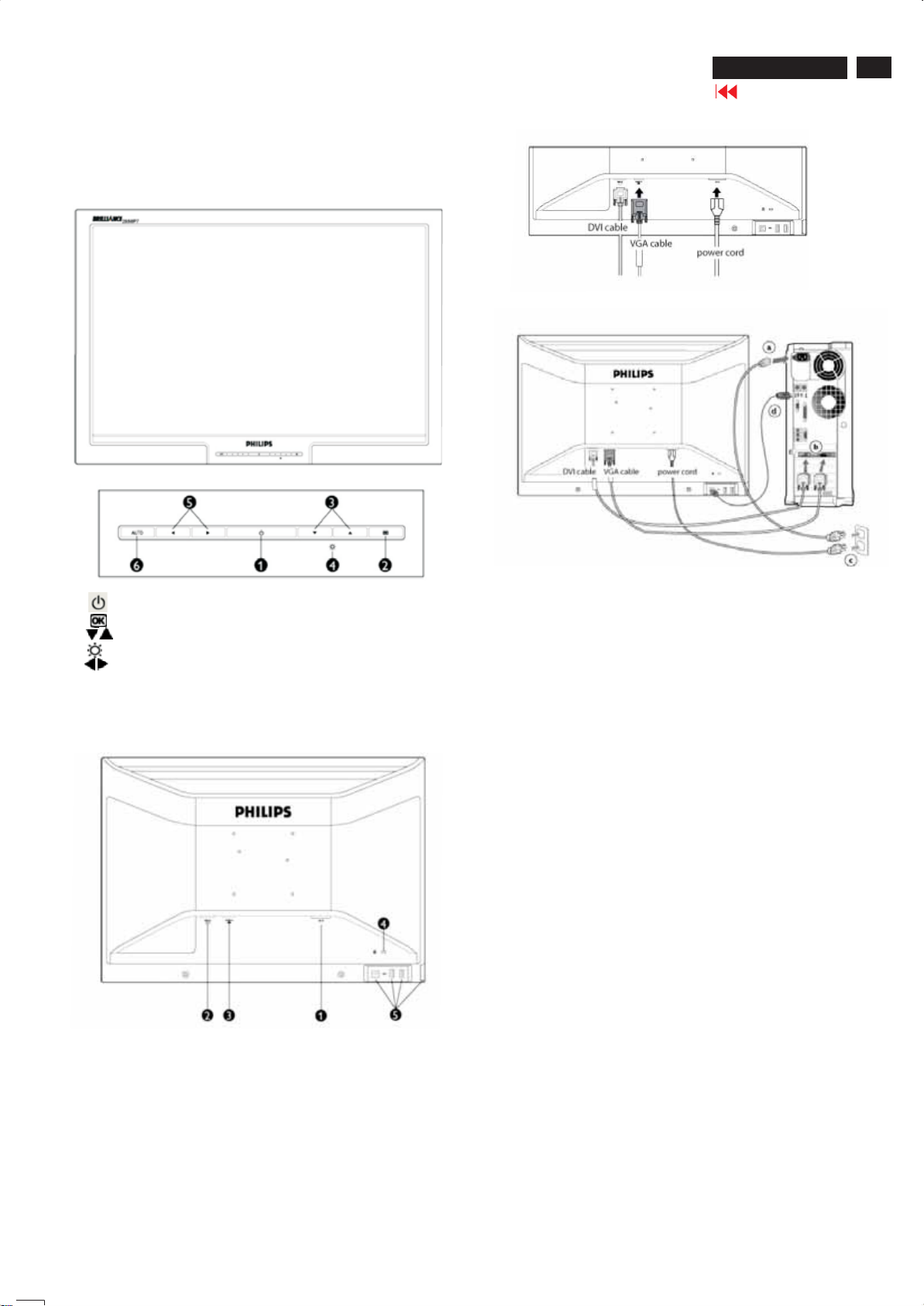
Installing Your LCD Monitor
Front ViewProduct Description
Connection to PC
200WP7 LCD
Go to cover page
5
1To switchmonitor's power On and Off
2To access OSD menu
3Toadjustthe OSD
4Toadjust brightness of the display
5Toadjustthe OSD
AUTO
6Automatically adjustthe horizontal position,
vertical position, phaseand cloc
Rear Vi ew
ksetting
http://www.wjel.net
1ACpower input
2DVI-Iinput
3D-SUBInput
4Kensington anti-thieflock
5USBupstream and downstream
Connect thecables to the back ofyourcomputer by followingthese
steps:
(a)Turn off yourcomputer and unplug its power cord.
(b)Connect the monitor signal cabletothevideo connector on the back
ofyourcom
(c)Plugthepower cord onyourcomputer and your monitor into a nearby
outlet.
(d)USB plug
(1) Connect USB upstream port onmonitor and the USB port onPC
(2) The USB downstream port is now ready for any USB device to
(
e)Turn onyourcomputer and monitor.Ifthe monitor displays animage,
installationiscomplete.
Note: The USB plug is apass through connectionwhether itcan
support USB 1.1 or USB 2.0 depends onyour PC's specification
puter
with a USB cable.
plug in
Connect to PC
Connect thepower cord and DVI cabletothe back of the monitor firmly.
(Philipshas pre-connectedVGA cable for the first installation.)
6
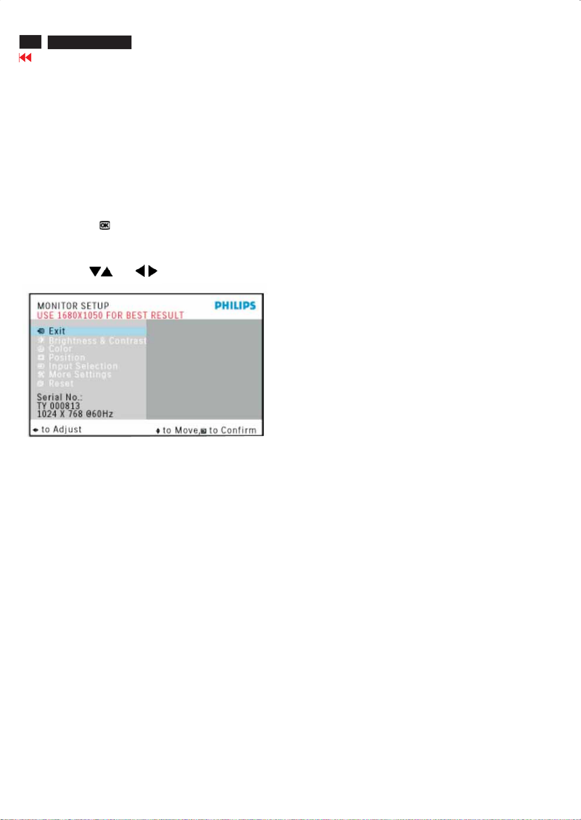
Description of the On Screen Display
What is the On-Screen Display?
This is a feature in all Philips LCD monitors. It allows an end user to
adjust screen performance of the monitors directly through an on-screen
instruction window. The user interface provides user-friendliness and
ease-of-use when operating the monitor.
Basic and simple instruction on the control keys.
When you press the button on the front control of your monitor,
the On-Screen Display (OSD) Main Controls window will pop up and
you can then start making adjustments to your monitor's various
features. Use the or the keys to make your adjustments
200WP7 LCD
Go to cover page
On Screen Display
The OSD Tr ee
Below is an overall view of the structure of the On-Screen Display. You can use this as a reference when you want to work
your way around the different adjustments later on.
http://www.wjel.net
On Screen Display
200WP7 LCD
Go to cover page
7
http://www.wjel.net
8
200WP7 LCD
Go to cover page
On Screen Display
http://www.wjel.net
On Screen Display
200WP7 LCD
Go to cover page
9
http://www.wjel.net
10
200WP7 LCD
Go to cover page
All units that are returned for service or repair must pass the
original manufactures safety tests. Safety testing requires both
and testing.Hipot Ground Continuity
HI-POT TEST INSTRUCTION
1.Application requirements
1.1 All mains operated products must pass the Hi-Pot test as
described in this instruction.
1.2 This test must be performed again after the covers have
been refitted following the repair, inspection or modification
of the product.
Test method
2.
2.1 Connecting conditions
2.1.1 The test specified must be applied between the parallel-
blade plug of the mainscord and all accessible metal
parts of the product.
2.1.2 Before carrying out the test, reliable conductive
connections must be ensured and thereafter be
maintained throughout the test period.
2.1.3 The mains switch(es) must be in the "ON" position.
2.2 Test Requirements
All products should be HiPot and Ground Continuity tested as
follows:
3. Equipments and Connection
3.1. Equipments
For example :
- ChenHwa 9032 PROGRAMMABLE AUTO SAFETY
TESTER
- ChenHwa 510B Digital Grounding Continuity Tester
- ChenHwa 901 (AC Hi-pot test), 902 (AC, DC Hi-pot test)
Withstanding Tester
3.2. Connection
* Turn on the power switch of monitor before Hipot and
Ground Continuity testing.
Clip
Clip
Condition HiPot Test for HiPot Test for Ground Continuity
products where products where Test requirement
the mains input the mains input is
range is Full 110V AC(USA
range(or 220V type)
AC)
Test 2820VDC 1700VDC Test current:
voltage (2000VAC) (1200VAC) 25A,AC
Test time:
Test time 3 seconds 1 second 3 seconds(min.)
(min.) Resistance
required:
Trip set at 100 uA 5 mA <=0.09+Rohm,
current for Max. R is the
(Tester) limitation; set resistance of
at 0.1 uA for the mains cord.
Min. Limitation
Ramp set at 2
time seconds
(Tester)
http://www.wjel.net
2.2.1 The minimum test duration for Quality Control Inspector
must be 1 minute.
2.2.2 The test voltage must be maintained within the specified
voltage + 5%.
(ChenHwa 9032 tester)
Video cable
Connect the "video cable"
or "grounding screw"
to the CLIP on your tester.
Grounding screw
Connect the power cord
to the monitor.
2.2.3 There must be no breakdown during the test.
2.2.4 The grounding blade or pin of mains plug must be
conducted with accessible metal parts.
Power outlet
4. Recording
Hipot and Ground Continuity testing records have to be kept
for a period of 10 years.
(Rear view of monitor)
200WP7 LCD
Go to cover page
11
Front View
To Lock/Unlock OSD FUNCTION(User Mode)
The OSD function can be locked by pressing"OK"button for more
than 10 seconds, the screen shows following windows for 3 seconds.
Everytime when you press"AUTO" or "OK" button, this message appears on the screen automatically.
WAIT FOR AUTOMATIC ADJUSTMENT
This screen appears when you press the "AUTO" buttons at the same
time. It will disappear when the monitor is properly adjusted
ATTENTION SIGNAL
WAITING FOR AUTOMATIC ADJUSTMENT
Access Aging.. Mode
Step 1 : Turn off LCD monitor, and disconnect Interface Cable
between Monitor and PC.
Step 2 : [Push " " & " " buttons at the same time and
hold it]+[Press power " " button until comes out " AGING screen"
] => then release all buttons.
Bring up:
AGING...
After 15 seconds, bring up:
ATTENTION SIGNAL
OSD MAIN CONTROLS LOCKED
Unlock OSD function
Locked OSD function can be released by pressing "OK" button for more
than 10 seconds again
ATTENTION SIGNAL
OSD MAIN CONTROLS UNLOCKED
http://www.wjel.net
NO VIDEO INPUT
This screen appears if there is no video signal input. Please check that
the signal is properly connected to the video card of PC and make sure
PC is on
After 15 seconds, bring up:
AGING...
After 15 seconds, bring up:
----------
---------repeatly
Connect Signal cable again=> go back to normal display
ATTENTION SIGNAL
CHECK CABLE CONNECTION
12
200WP7 LCD
Go to cover page
Front Control Panel
Access Factory Mode
How to get into Factory Mode Menu
Step1:
Turn off monitor.
Step2:
[Push " " & " " buttons at the same time and hold it]
+[Press power " " button untill comes out "Windows screen" ]
=> then release all buttons
Step3:
Press OK " " button, bring up Factory mode indication as shown
in Fig2.
http://www.wjel.net
Factory Mode indicator
200WP7 LCD
Go to cover page
13
Philips' Flat Panel Monitors Pixel Defect Policy
Philips strives to deliver the highest quality products. We use some of
the industry's most advanced manufacturing processes and practice
stringent quality control. However, pixel or subpixel defects on the TFT
LCD panels used in flat panel monitors are sometimes unavoidable.
No manufacturer can guarantee that all panels will be free from pixel
defects, but Philips guarantees that any monitor with an unacceptable
number of defects will be repaired or replaced under warranty.
This notice explains the different types of pixel defects and defines
acceptable defect levels for each type. In order to qualify for repair or
replacement under warranty, the number of pixel defects on a TFT LCD
panel must exceed these acceptable levels.
For example, no more than 0.0004% of the subpixels on a 15" XGA
monitor may be defective. Furthermore, Philips sets even higher quality
standards for certain types or combinations of pixel defects that are
more noticeable than others. This policy is valid worldwide .
Pixels and Subpixels
A pixel, or picture element, is composed of three subpixels in the
primary colors of red, green and blue. Many pixels together form an
image. When all subpixels of a pixel are lit, the three colored subpixels
together appear as a single white pixel. When all are dark, the three
colored subpixels together appear as a single black pixel.
Other combinations of lit and dark subpixels appear as single pixels of
other colors.
Types of Pixel Defects
Pixel and subpixel defects appear on the screen in different ways.
There are two categories of pixel defects and several types of subpixel
defects within each category.
Bright Dot Defects Bright dot defects appear as pixels or subpixels that
are always lit or "on".
These are the types of bright dot defects:
Black Dot Defects
Black dot defects appear as pixels or subpixels that are always dark or
"off".
These are the types of black dot defects:
One dark subpixel
Two or three adjacent dark subpixels
Proximity of Pixel Defects
Because pixel and subpixels defects of the same type that are nearby
one another may be more noticeable, Philips also specifies tolerances
for the proximity of pixel defects.
Pixel Defect Tolerances
In order to qualify for repair or replacement due to pixel defects during
the warranty period, a TFT LCD panel in a Philips flat panel monitor
must have pixel or subpixel defects exceeding the tolerances listed in
the following tables.
One lit red, green or blue subpixel
http://www.wjel.net
Two adjacent lit subpixels:
- Red + Blue = Purple
- Red + Green = Yellow
- Green + Blue = Cyan (Light Blue)
Three adjacent lit subpixels
(one white pixel)
Note:
* 1or2 adjacent sub pixel defects = 1 dot defect
Your Philips monitor is ISO13406-2 Compliant
14
Quick reference for failure mode of LCD panel
this page presents problems that could be made by LCD panel.
It is not necessary to repair circuit board. Simply follow the mechanical
instruction on this manual to eliminate failure by replace LCD panel.
200WP7 LCD
Go to cover page
Failure Mode Of Panel
Polarizer has bubbles
Failure description
Vertical block defect
Vertical dim lines
Vertical lines defect
(Always bright or dark)
Horizontal block defect
Phenomenon
Polarizer has bubbles
Foreign material inside
polarizer. It shows liner or
dot shape.
Concentric circle formed
Horizontal dim lines
Horizontal lines defect
(Always bright or dark)
Has bright or dark pixel
Bottom back light of LCD is
brighter than normal
Back light un-uniformity
http://www.wjel.net
Backlight has foreign material.
Black or white color, liner or
circular type

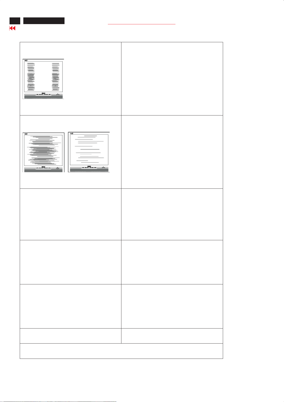
Troubleshooting
This page deals with problems that can be corrected by a user. If the problem still persists after you have tried these
solutions, contact Philips customer service representative.
Common Probl ems
Having this problem Check these items
No Picture
(Power LED not lit)
· Make sure the power cord is plugged into the
power outlet and into the back of the monitor.
· First, ensure that the power button on the front
of the monitor is in the OFF position, then
press it to the ON position.
200WP7 LCD
Go to cover page
15
No Picture
(Power LED is amber or yellow)
Screen says
AUTO button not working properly
· Make sure the computer is turned on.
· Make sure the signal cable is properly
connected to your computer.
· Check to see if the monitor cable has bent
pins.
· The Energy Saving feature may be activated
· Make sure the monitor cable is properly
connected to your computer. (Also refer to the
Quick Set-Up Guide).
· Check to see if the monitor cable has bent
pins.
· Make sure the computer is turned on.
· The Auto Function is designed for use on
standard Macintosh or IBM-compatible PCs
running Microsoft Windows.
· It may not work properly if using nonstandard
PC or video card.
http://www.wjel.net
Imag ing Pro blems
Display position is incorrect
Image vibrates on the screen Check that the signal cable is properly connected to the
· Press the Auto button.
· Adjust the image position using the
Phase/Clock of More Settings in OSD Main
Controls.
graphics board or PC
16
200WP7 LCD
Go to cover page
Troubleshooting
Vertical flicker appears
Horizontal flicker appears
· Press the Auto button.
· Eliminate the vertical bars using the
Phase/Clock of More Settings in OSD Main
Controls.
· Press the Auto button.
· Eliminate the vertical bars using the
Phase/Clock of More Settings in OSD Main
Controls.
The screen is too bright or too dark
An after-image appears
An after-image remains after the power has been turned
off.
http://www.wjel.net
· Adjust the contrast and brightness on Monitor
Setup. (The backlight of the LCD monitor has a
fixed life span. When the screen becomes dark
or begins to flicker, please contact your
dealer).
· If an image remains on the screen for an
extended period of time, it may be imprinted in
the screen and leave an after-image. This
usually disappears after a few hours
· This is characteristic of liquid crystal and is not
caused by a malfunction or deterioration of the
liquid crystal. The after-image will disappear
after a peroid of time.
Green, red, blue, dark, and white dots remains The remaining dots are normal characteristic of the liquid
crystal used in today’s technology
For further assistance, refer to the Consumer Information Centers list and contact Philips customer service
representative
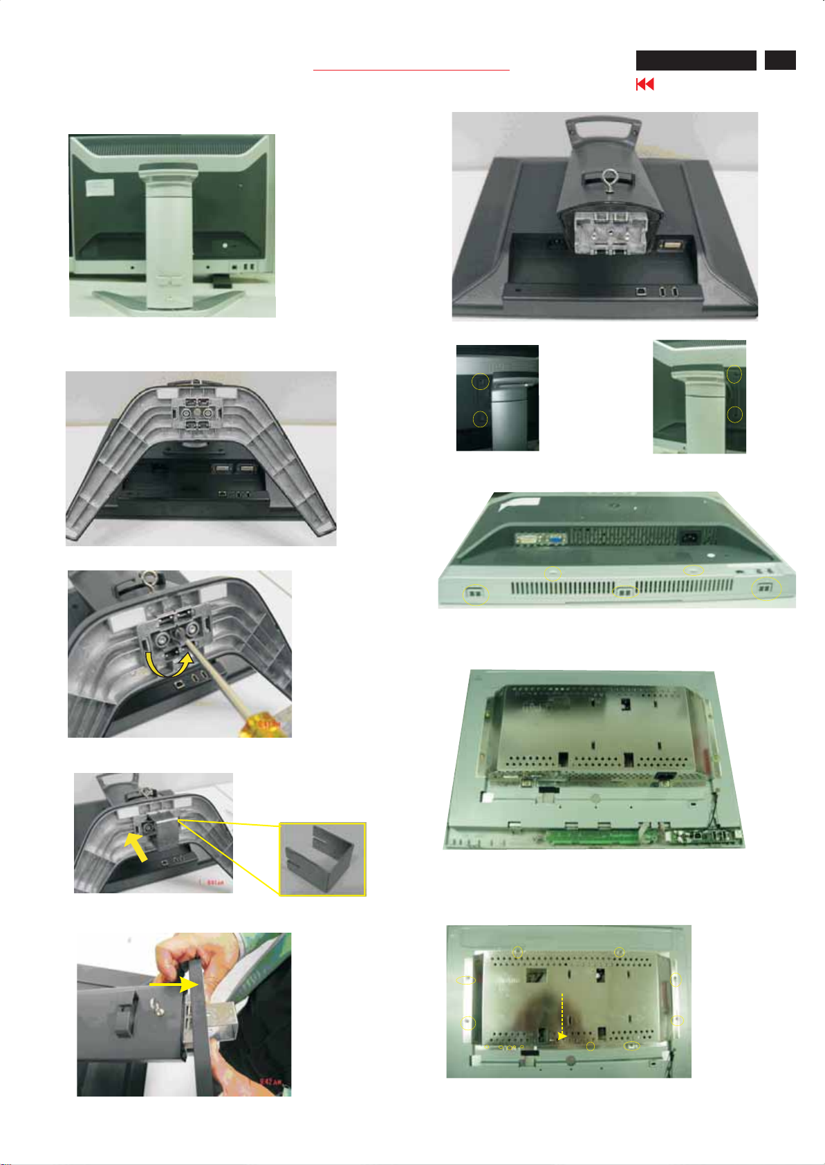
1.Back view as Fig.1
Mechanical Instructions
Fig.1
200WP7 LCD
Go to cover page
17
Fig.6
2.remove the base
Step 1: Place the monitor face down on a smooth surface as Fig 2.
-
Be carefully to prevent the scratch and injury during the uninstallation.
Fig.2
Step 2: Unfasten one screw on the base stand as Fig 3.
Fig.3
Step 3: Firmly insert the base removal tool into four-pronged clicks as Fig 4
3. Remove cable base as Fig7 and Fig.8
Unscrew the screws
Fig.7
Fig.8
4.Remove back cover as Fig.9 and Fig.10
Fig.9
Unscrew the 2 screws and open the clicks on the sides
Fig.10
Fig.4
http://www.wjel.net
Step 4: Pull out the foot from base as Fig 5 Fig.6.
Base Column Base standBase Column Base stand
5.Remove the shielding
-Unscrew the screws and then pull down the shielding as Fig.11 Fig.12
Fig.12
Fig.5
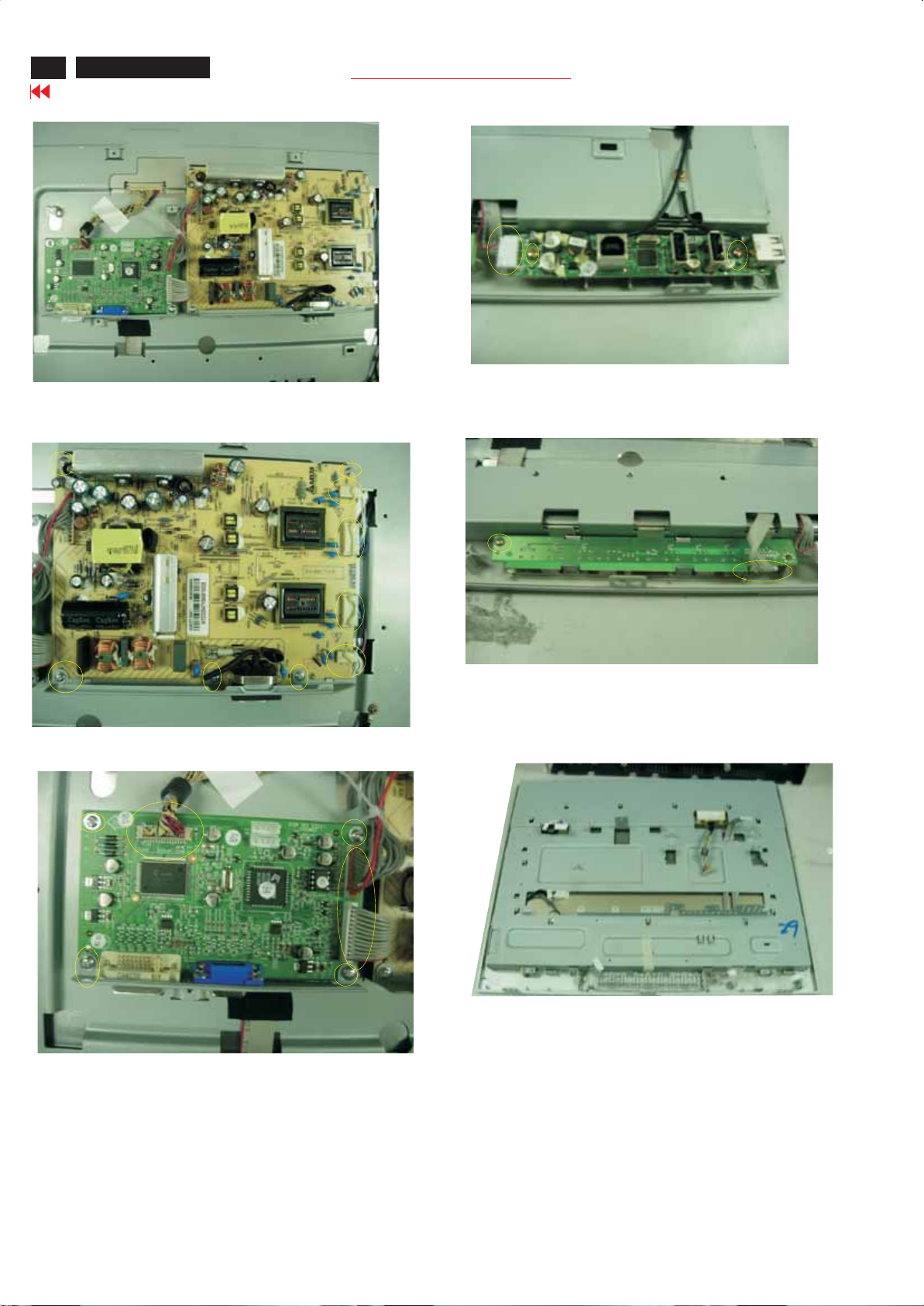
18
200WP7 LCD
Go to cover page
Mechanical Instructions
Fig.11
Fig.15
6.Remove the power board and scaler board
-unscrew the screws and disconnect the connectors as Fig.13,Fig.14
Fig.13
8. Remove the control board
-unscrew the screws and disconnect the connector as Fig.16
Fig.16
http://www.wjel.net
Fig.14
7.Reomve the USB board
-Disconnect the connector and unscrew the screws as shown in Fig.15
Display Adjustment
200WP7 LCD
Go to cover page
19
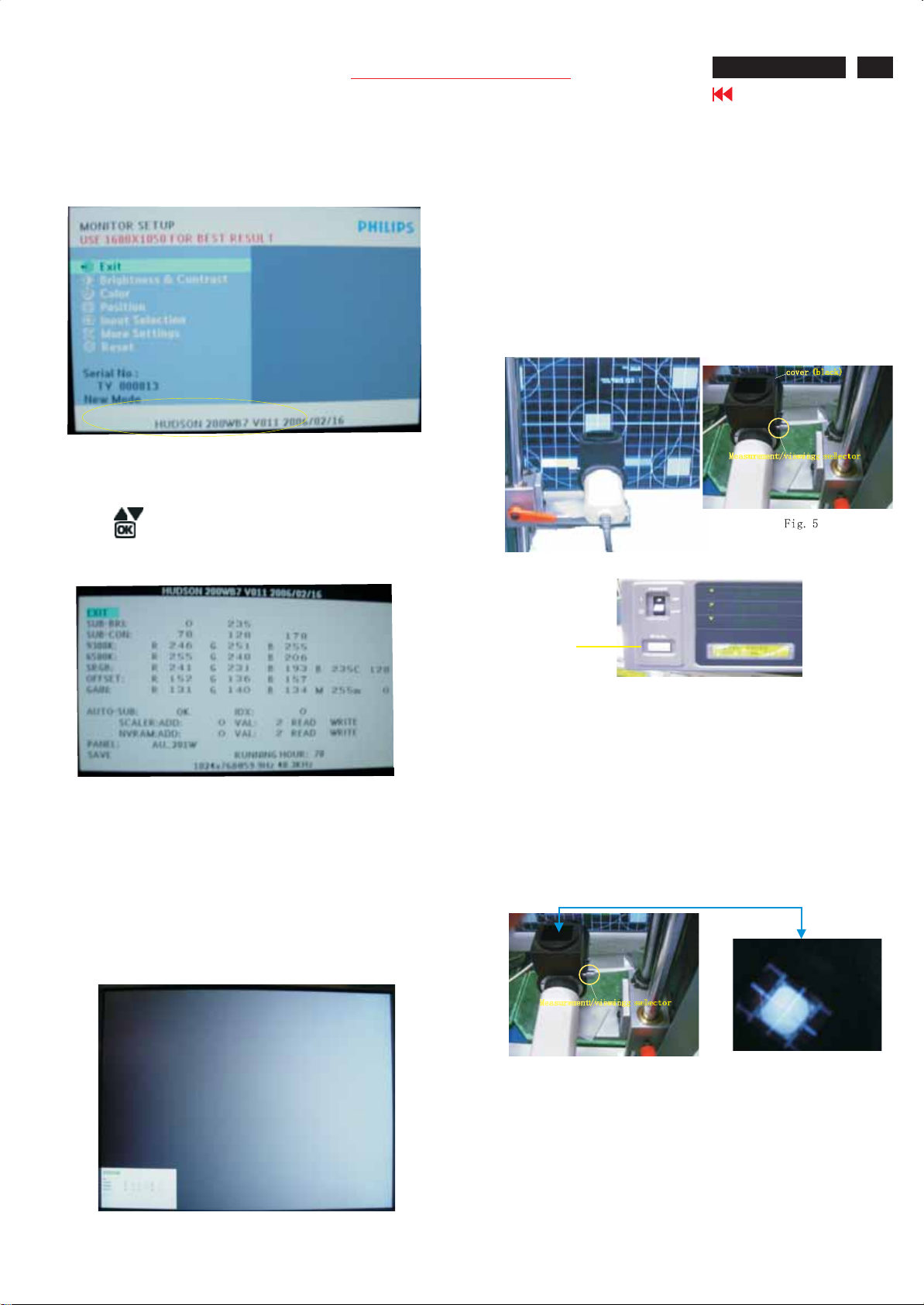
TO access factorymode
1. Turn off monitor(do not turn off PC)
2. Press AUTO , OK and thepower simultaneously on the frond control
panel, then press OK waittill the OSD menu comeon the screen of
monitor.
Fig.1
3.If OSD menu disappears on the screen ofmonitor. press OK
again(anytime), then the OSD menu comes on the screen again.
4. Usetoselect OSD menu.
5. Usetoaccess/confirm the selection.
Move thecursor to yellow area (see red circleo
press OK button to access to factorymode.(see Fig.2)
nFig.1)
2. Apply a 1280x1024/60Hz signal with white pattern.Set
brightness control at 100% and contrast control at 50%. Adjust
the R.G.B gain to reach special color temperature on center of screen.
2.1Aim the probe CA-A30 at the center of screen as Fig. 4
2.2 Remove the lens protective cover of probe CA-A30.
2.3 Set Measuring/viewing selector to Measuring position for reset
analyzer. (Zero calibration) as Fig. 5
2.4 Turn on the colour analyzer (CA-110).
2.5 Press 0-CAL button to start reset analyzer. See Fig. 6
Fig.4
Fig.2
PC mode WHITE-D adjustment (B)
1 Apply 1280X1024/60Hz mode with 64gray level pattern as Fig
3. Set maincontrolsbrightness control at 100% and contrast to
50% on User mode. Set color setting at original panel color on
User mode. Move cursor to "Auto-SUB" item on factory mode,
press "OK" key to activate thisfunction.
http://www.wjel.net
O-CAL
Fig.6
2.6Switch light probe to Viewing position.
2.7 Move the Lens barrel forward or backward to get clear image
as shown in Fig. 7
2.8Switch light probe to Measuring position. It should be able to
indicate colour value on the CA-110.
Fig.3
Fig.7
20
2.9 Adjust the R, G, B Sub-Gain on factory mode for the screen
center, the 1931 CIE chromaticity (X, Y) co-ordinates shall be
as follows.
Use Minolta CA-110 for colour coordinates and luminance check.
Luminance is > 250 Nits in the center of the screen when
brightness at 100% and contrast set to 100%.
200WP7 LCD
Go to cover page
9300°K 6500°K
x (center) 0.283 ± 0.005 0.313 ± 0.005
y (center) 0.297 ± 0.005 0.329 ± 0.005
sRGB
x(center) 0.313 ± 0.008
y(center) 0.329 ± 0.008
Ynits 220 ± 10
Factory Preset (B):
After finished all the adjustment, set:
OSD Default Setting:
Brightness: 100%
Contrast: 50%
Adjust size: Full screen
Language: English
Colour: 6500K
OSD position: middle of the LCD screen
Input Selection: Default as PC VGA (D-sub)
Signal cable: Connect to the monitor for user (VGA)
http://www.wjel.net
DDC Instructions
200WP7 LCD
Go to cover page
21
General
DDC Data Re-programming
In case the DDC data memory IC or main EEPROMwhich storageall
factory settings were replaced due to a defect, the serial numbers have
to be re-programmed"".
It is advised to re-soldered DDC IC and main EEPROMfrom the old
board onto thenew board if circuit board have been replaced, in this
case the DDC data does not need to be re-programmed.
Additional information
Additional information about DDC (Display Data Channel) may be
obtained f
Display Identification Data(EDID) information may be also obtained from
VESA.
rom Video Electronics Standards Association (VESA). Extended
Analog DDC IC, & EEPROM
System and equipment requirements
1. An i486 (or above) personal computer or compatible.
2. Microsoftoperation system Windows 95/98 .
Y o Install the EDID_PORT_Tool under Win2000/XP.As
ou havet
Fig.1.
Fig.1Fig. 1
A. Copythe "UserPort.sys" to C:\WINNT\system32\drivers(win2000)
C:\WINDOWS\system32\drivers(winXP)
B. Runnin
3. EDID45.1exe program .
4. DDC 2BI-ISP TOOL:
g"io.exe" everytime, Before you start to programming
edid data .
Pin Assignment
Input DVI-D connector pin assignment
To Printer port
DC 8~12V
DC 8~12V
Power
indicator
Pin No. Description
Power
indicator
1 TMDS data22 TMDS data2+
3 TMDS data2/4 shield
4NC
5NC
6 DDC clock
7 DDC data
8NC
9 TMDS data110 TMDS data1+
11 TMDS data1/3 shield
12 NC
13 NC
14 +5V
15 Ground (return for +5V and H/Vsync)
16 Hot plug detect
17 TMDS data018 TMDS data0+
19 TMDS data0/5 shield
20 NC
21 NC
22 TMDS clock shield
23 TMDS clock+
24 TMDS clock-
To Monitor
D-sub/DVI cable
To Monitor
D-sub cable
Fig.3Fig. 3
Inclusion :
A. DDC2BI-ISP TOOL(3138 106 10396) x1 (as Fig.2)
B. Printer cable x1
c. (D-Sub) to (D-Sub) cable x2
D. D-SUB to DVI cable X1
Note:The EDID45.1EXE is a windows-based program, which cannot
be run in MS-DOS.
To Printer port
http://www.wjel.net
Fig.2Fig. 2
Fig.4Fig. 4
Input analog D-SUB connector pin assignment
PIN No. SIGNAL
1Red
2 Green/ SOG
3Blue
4 Sense (GND)
5NC
6RedGND
7 Green GND
8BlueGND
9 DDC +5V
10 Cable detect (GND)
11 Sense (GND)
12 Bi-directional data
13 H/H+V sync
14 V-sync
15 Data clock
Fig.5

22
200WP7 LCD
Go to cover page
DDC Instructions
Configuration and procedure
There are 3 chips contained OSD string, serial number..etc
on the circuit board, main EEPROM which storage all factory settings,OSD
string. DDC IC which storage 128byte EDID data(serial number ..etc.).
Following descirptions are the connection and procedure for Analog
/Digital and main EEPROM can be re-programmed along with
Analog/Digital IC by enable factory memory data write function on the
DDC program (EDID45.EXE).
Initialize alignment box
In order to avoid that monitor entering power saving mode due
to sync will cut off by alignment box, it is necessary to initialize
alignment box before running programming software
(EDID45.EXE). Following steps show you the procedures and
connection.
Step 1: Supply 8-12V DC power source to the Alignment box by
plugging a DC power cord or using batteries.
Step 2: Connecting printer cable and D-Sub cable of monitor as Fig. 5
PC
1=Power connector
2= D-SUB/D VI connector
3. At the submenu, type the letter of your computer's hard disk drive
followed by :EDID45 (for example, C:\EDID45, as shown in Fig. 7).
Edid45.exe
Fig. 7
4. Click button. The main menu appears (as shown in Fig. 8).OK
This is for initialize alignment box.
TP1)
L
DC Power
8-12 V
----->
2
Printer
Port
To PC
To Monitor
Fig. 5
To printer port (
Step 3: Installation of EDID45.EXE
Method 1: Start on DDC program
Start Microsoft Windows.
1. The Program"EDID45.EXE" in service manual cd-rom be copyed to C:\ .
2. Click , choose Run at start menu of Windows as shown
In Fig. 6.
----->
1
http://www.wjel.net
Fig. 8
Note 1: If the connection is improper, you will see the following error
message (as shown in Fig. 9) before entering the main menu.
Meanwhile, the (read EDID) function will be disable. At this
time,
please make sure all cables are connected correctly and
Edid45.1
Fig. 9
1
Note 2: During the loading, EDID45 will verify the EDID data which just
loaded from monitor before proceed any further function, once
the data structure of EDID can not be recognized, the following
error message will appear on the screen as below. Please
confirm following steps to avoid this message.
1. The data structure of EDID was incorrect.
2. DDC IC that you are trying to load data is empty.
3. Wrong communication channel has set at configuration setup
Fig. 6
Fig. 10
DDC Instructions
200WP7 LCD
Go to cover page
23
Re-programming Analog DDC IC
Step 1: After initialize alignment box, connecting all cables and
box as shown in Fig. 11
1=Power connector
2= D-SUB connector
PC
TP1)
L
To PC
To printer port (
To Monitor
Printer
Port
Step 2: Read DDC data from monitor
1. Click icon as shown in Fig. 11 from the tool bar to bring up
the Channels "Configuration Setup" windows as shown in Fig. 12.
Fig. 11
Step 3: Modify DDC data (verify EDID version, week, year)
1. Click (new function) icon from the tool bar, bring up
Step 1 of 9 as shown in Fig. 15 .
EDID45 DDC application provides the function selection and
text change (select & fill out) from Step 1 to Step 9.
To Printer port
To Printer port
To Printer port
DC 8~12V
DC 8~12V
DC 8~12V
DC 8~12V
DC 8~12V
Power
Power
indicator
indicator
Power
Power
indicator
indicator
Step 4: Modify DDC data (Monitor Serial No.)
- Serial number can be filled up or be changed at this moment.
- Click Finish to exit the Step window.
Next1. Click to step7, bring up Fig. 16.
To Monitor
To Monitor
D-sub/DVI cable
To Monitor
D-sub/DVI cable
To Monitor
To Monitor
D-sub/DVI cable
D-sub cable
D-sub cable
Fig. 15
Fig. 12
2. Select the DDC2Bi as the communication channel.
As shown in Fig. 13.
Fig. 13
3. Click OK button to confirm your selection.
4. Click icon (Read EDID function) to read DDC EDID data from
monitor. The EDID codes will display on screen as shown in Fig. 14.
http://www.wjel.net
Fig. 16
Step 5: Write DDC data
1. Configuration should be as Fig. 17. And press OK.
To Printer port
To Printer port
Fig. 17
Fig. 14
24
200WP7 LCD
Go to cover page
DDC Instructions
2. Access Factory Mode
- Turn off monitor.
-
[PushAUTO" "&OK" "buttonsatthesametimeand
holdit]+[Press power " " button untill comes out "Windows
screen"] => then release all button
3. Click (Write EDID) icon from the tool bar to write DDC data.
Step 6: Save DDC data
Sometimes, you may need to save DDC data as a text file for using
in other IC chip. To save DDC data, follow the steps below:
1. Click (Save) icon (or click "file"-> "save as") from the tool bar
And give a file name as shown in Fig. 18.
The file type is EDID45 file (*.ddc) which can be open in WordPad.
By using WordPad, the texts of DDC data & table (128 bytes, hex
code) can be modified. If DDC TEXTS & HEX Table are completely
correct, it can be saved as .ddc flie to re-load it into DDC IC for DDC
Data application.
200WP7
Step :8 Modify serial number in OSD
-1. Unzip the serial number.zip to your computer, then open the folder
as shown in Fig.20.
-2.IfuseWin98 OS, you can execute SN.exe directly.
If use Win2000 or XP OS, first, you must execute install.bat, then
execute SN.exe
-3. Set I2C bus(press the left-top button of operating window) as shown
in Fig.21, then press " SET" button.
-4. Set Block2 as shown in Fig.22
-5. key in new serial number, then press " Write" button as shown in
Fig.22 , Click " WRITE" button.
-6. It will appear" Serial Number Write OK" , Click" Enter" to finish it.
Fig.20
Analog
Fig. 25
2. Click .Save
Step 7: Exit DDC program
Pull down the File menu and select Exit as shown in Fig. 19.
Edid45.1
http://www.wjel.net
Fig. 19
Fig.18
Fig.21
Fig.22
Step9:
-1. Disconnect the monitor power cord and connect it again.
-2. Press the OK button to bring up the OSD main manu.
-3. Re-confirm the serial Number is updated as shown in Fig.23.
Fig.23
DDC Instructions
200WP7 LCD
Go to cover page
25
Re-programming Digital DDC IC
Step 1: After initialize alignment box, connecting all cables and
box as shown in Fig. 24
1=DVI connector
2= D-SUB connector
3=Power Plug
3
To PC
To Monitor
Printer
Port
Fig.24
Step 2: Read DDC data from monitor
1. Click icon as shown in Fig. 25 from the tool bar to bring up
the Channels "Configuration Setup" windows as shown in Fig. 26.
Step 3: Modify DDC data (verify EDID version, week, year)
1. Click (new function) icon from the tool bar, bring up
Step 1 of 9 as shown in Fig. 28.
EDID45 DDC application provides the function selection and
text change (select & fill out) from Step 1 to Step 9.
To Printer port
To Printer port
DC 8~12V
Power
indicator
Step 4: Modify DDC data (Monitor Serial No.)
DC 8~12V
DC 8~12V
DC 8~12V
D-sub/DVI cable
Power
indicator
Next1. Click , bring up Fig. 29. Then select Digital Signal as below
To Monitor
To Monitor
D-sub/DVI cable
To Monitor
To Monitor
D-sub/DVI cable
D-sub cable
Fig. 28
Fig. 25
2. Select the DDC2Bi as the communication channel.
As shown in Fig. 26.
Fig. 26
3. Click OK button to confirm your selection.
4. Click icon (Read EDID function) to read DDC EDID data from
monitor. The EDID codes will display on screen as shown in Fig. 27.
http://www.wjel.net
Fig. 29
2. Click to step7, bring up Fig. 30.Next
- Serial number can be filled up or be changed at this moment.
- Click Finish to exit the Step window.
To Printer port
Fig. 27
Fig. 30
26
200WP7 LCD
Go to cover page
DDC Instructions
Step 5: Write DDC data
1. Configuration should be as Fig. 31. And press OK.
Fig. 31
2. Access Factory Mode
- Turn off monitor.
-
[PushAUTO" "&OK" "buttonsatthesametimeand
holdit]+[Press power " " button untill comes out "Windows
screen"] => then release all button
3. Click (Write EDID) icon from the tool bar to write DDC data.
Step 6: Save DDC data
Sometimes, you may need to save DDC data as a text file for using
in other IC chip. To save DDC data, follow the steps below:
BOMCode
Panel Supplier CODE
AUO 1
CPT 2
LPL(LG)3
QDI4
CMO 5
B Z 3A0601 000001
SERIALNO
YEAR/WEEK
SERVICE VERSIONCHANGE CODE
BOMCODE(BILL OF MATE RIAL)CODE
SITE CODE(PRODUCTIONCENTER)
BZCODE(AR-CZECH REPUBLIC
VN-HUNGARY(SZR),BZ-SUZHOU
DS-DONGGUAN)
1. Click (Save) icon (or click "file"-> "save as") from the tool bar
And give a file name as shown in Fig. 32.
The file type is EDID46 file (*.ddc) which can be open in WordPad.
By using WordPad, the texts of DDC data & table (128 bytes, hex
code) can be modified. If DDC TEXTS & HEX Table are completely
correct, it can be saved as .ddc flie to re-load it into DDC IC for DDC
Data application.
200P7
Fig. 32
2. Click .Save
http://www.wjel.net
Step 7: Exit DDC program
Pull down the File menu and select Exit as shown in Fig. 33.
Edid45.1
Fig. 33

DDC Data
200WP7 LCD
Go to cover page
27
THE DISPLAY DATA CHANNEL (DDC 2B) CONTENTINCLUDING
(FOR HUDSON 7-200WP7 AnalogAUOpanel)
**********************************************************************
EDID logfile for 200WP7 Analog
**********************************************************************
Vendor/Product Identification
ID Manufacturer Name :PHL
IDProduct Code :0843 (HEX.)
IDSerial Number : 123456 (DEC.)
Week of Manufacture :50
Year of Manufacture : 2005
EDID Version,Revision
Version : 1
Revision :3
Basic DisplayP
Video Input Definition :Analog Video Input
MaximumHImage Size :43
Maximum VImage Size :27
Display Transfer Characteristic :2.2
Feature
Display Type :RGBcolor display
Standard Default Color Space :Primary color space
Preferred Timing Mode :Detailed timing block 1
Color Characteristics
Red X coordinate :0.64
Red Y coordinate : 0.352
Green X coordinate :0.288
Green Y coordinate :0.628
Blue X coordinate :0.144
Blue Y coordinate : 0.076
White X coordinate :0.313
ite Y coordinate : 0.329
Wh
Established Timings
Established TimingsI :
Established TimingsII :
Manufacturer'stimings : 1152 x 870 @75Hz (Apple,Mac II)
Standard Timing Identification #1
Horizontal activepixels : 1152
Aspect Ratio :4:3
RefreshRate :70
Standard Timing Identification #2
Horizontal activepixels : 1152
Aspect Ratio :4:3
RefreshRate :75
arameters/Features
0.700V/0.300V (1.00Vpp)
without Blank-to-BlackSetup
Separate Sync
Composite Sync
Sync on Green
no Serration required
(gamma)
Support (DPMS) : Standby
720 x 400 @70Hz (IBM ,VGA)
800 x 600 @72Hz (VESA)
To Printer port
640 x 480 @60Hz (IBM,VGA)
640 x 480 @67Hz (Apple,Mac II)
640 x 480 @72Hz (VESA)
640 x 480 @75Hz (VESA)
800 x 600 @56Hz (VESA)
800 x 600 @60Hz (VESA)
800 x 600 @75Hz (VESA)
832 x 624 @75Hz (Apple,Mac II)
1024 x 768 @60Hz (VESA)
http://www.wjel.net
1024 x 768 @70Hz (VESA)
1024 x 768 @75Hz (
1280x1024 @75Hz (VESA)
Suspend
Active Off
VESA)
Standard Timing Identification #3
Horizontal activepixels : 1280
Aspect Ratio :4:3
RefreshRate :60
Standard Timing Identification #4
Horizontal activepixels : 1280
Aspect Ratio :5:4
RefreshRate :60
Standard Timing Identification #5
S
tandard Timing Identification #6
Power
Standard Timing Identification #7
indicator
Detailed Timing#1
Monitor Descriptor #2
Monitor Descriptor #3
Monitor Descriptor #4
Extension Flag:0
Check sum : 6C (HEX.)
**********************************************************************
EDID data (128bytes)
**********************************************************************
0: 00 1:ff 2:ff 3:ff 4:ff 5:ff 6:ff 7:00
8:41 9: 0c10: 43 11:0812: 40 13: e2 14: 0115: 00
16: 32 17: 0f 18:0119: 03 20: 1e 21:2b 22: 1b 23: 78
24: ee 25: cf 26: e
32: 13 33: 50 34: 54 35: bf36:ef 37: 8038:71 39: 4a
40: 71 41: 4f 42: 81 43: 40 44: 81 45: 8046:a9 47: 40
48: b3 49: 00 50: a951:4f 52:b3 53: 0f 54: 08 55: 39
56: 90 57: 30 58:62 59:1a 60: 27 61:40 62:68 63: b0
64: 36 65: 00 66: b1 67: 0f 68: 11 69: 00 70: 00 71: 1e
72: 00 73: 00 74: 00 75: ff 76: 00 77: 20 78: 54 79: 59
80: 20 81:20 82: 3183: 32 84: 33 85: 34 86: 35 87: 36
88:0a89: 20 90: 00 91: 00 92: 00 93: fc 94: 00 95: 50
96: 68
104: 30 105: 30 106: 57 107: 50 108:00109: 00 110: 00 111:fd
112: 00 113: 38114: 4c115: 1e 116: 62 117: 15 118:00119: 0a
120: 20 121:20122: 20 123: 20 124: 20 125: 20 126: 00 127: 6c
DC 8~12V
Horizontal activepixels : 1600
DC 8~12V
Aspect Ratio :4:3
RefreshRate :60
Horizontal activepixels : 1680
Power
indicator
Aspect Ratio : 16:10
RefreshRate :60
Horizontal activepixels : 1680
Aspect Ratio : 16:10
RefreshRate :75
Pixel Clock(MHz) : 146
HActive (pixels):
HBlanking(pixels):560
V Active (lines):1050
V Blanking(lines):39
HSync Offset (F Porch) (pixels): 104
HSync Pulse Width(pixels):176
V Sync Offset (F Porch) (lines): 3
V Sync Pulse Width(lines):6
H Image Size (mm) : 433
VImage Size (mm) : 271
HBorder
V Border (lines):0
Flags :Non-interlaced
Serial Number : TY 123456
Monitor Name :Philips 200WP
Monitor Range Limits
Min. Vt rate Hz : 56
Max. Vt rate Hz : 76
Min
Max. Horiz. rate kHz : 98
Max. Supported Pixel :210
No secondaryGTF timingformula supported.
(pixels):0
.Horiz. rate kHz : 30
97: 69 98:6c 99: 69 100: 70 101:73102: 20 103: 32
To Printer port
To Monitor
D-sub/DVI cable
To Monitor
D-sub cable
1680
:Normal Display, Nostereo
:Digital Separate sync.
:PositiveVerticalSync.
:Positive Horizontal Sync.
527:a328:5a 29: 49 30: a031:24

28
200WP7 LCD
Go to cover page
DDC Data
THE DISPLAY DATA CHANNEL (DDC 2B) CONTENT INCLUDING
(FOR HUDSON7-200WP7 DigitalQDIpanel)
**********************************************************************
EDID log file for 200WP7 Digital
**********************************************************************
Vendor/Product Identification
ID Manufacturer Name : PHL
ID Product Code : 0843 (HEX.)
ID Serial Number : 123456 (DEC.)
Week of Manufacture : 50
YearofManufacture : 2005
EDID Version, Revision
Version : 1
Revision : 3
Basic DisplayParameters/Features
Video Input Definition : Digital Video Input
Maximum H Image Size : 43
Maximum V Image Size : 27
DisplayTransfer Characteristic : 2.2
(gamm
Feature Support (DPMS) : no Standby
Display Type : RGB color display
Standard Default Color Space : Primary color space
Preferred Timing Mode : Detailed timing block 1
Color Characteristics
Red X coordinate:0.64
Red Y coordinate:0.352
Green X coordinate : 0.288
Green Y coordinate : 0.628
Blue X coordinate:0.144
Blue Y coordinate:0.076
WhiteXcoordinate:0.313
WhiteYcoordinate:0.329
Established Timings
Established Timings I : 720 x 400 @70Hz (IBM,VGA)
Established Timings II : 800 x 600 @72Hz (VESA)
Manufacturer's timings : 1152 x 870 @75Hz (Apple,M
Standard Timing Identification #1
Horizontal active pixels : 1152
Aspect Ratio : 4:3
Refresh Rate:70
Standard Timing Identification #2
Horizontal active pixels : 1152
Aspect Ratio : 4:3
Refresh Rate:75
Standard Timing Identification #3
Horizontal active pixels : 1280
Aspect Ratio : 4:3
Refresh Rate:60
a)
Compatible with VESA DFP 1.x
no Suspend
Active Off
640 x 480 @60Hz (IBM,VGA)
640 x 480 @67Hz (Apple,Mac II)
640 x 480 @72Hz (VESA)
640 x 480 @75Hz (VESA)
800 x 600 @56Hz (VESA)
800 x 600 @60Hz (VESA)
800 x 600 @75Hz (VESA)
832 x 624 @75Hz (Apple,Mac II)
1024 x 768 @60Hz (VESA)
1024 x 768 @70Hz (VESA)
1024 x 768 @75Hz (VESA)
1280 x 1024 @75Hz (VESA)
ac II)
http://www.wjel.net
Standard Timing Identification #6
Horizontal active pixels : 1680
Aspect Ratio : 16:10
Refresh Rate:60
Detailed Timing #1
Pixel Clock (MHz) : 146
HActive (pixels) : 1680
HBlanking (pixels) : 560
VActive (lines) : 1050
VBlanking (lines) : 39
H Sync Offset (F Porch) (pixels): 104
H Sync Pulse Width (pixels) : 176
V Sync Offset (F Porch) (lines) : 3
V Sync Pulse Width (lines) : 6
HImage Size (mm) : 433
VImage Size (mm) : 271
H Border (pixels) : 0
V Border (lines) : 0
Flags : Non-interlaced
Monitor Descriptor #2
Serial Number : TY 123456
Monitor Descriptor #3
Monitor Name : Philips 200WP
Monitor Descriptor #4
Monitor Range Limits
Min. Vt rateHz : 56
Max. Vt rateHz : 76
Min. Horiz. ratekHz : 30
Max. Horiz. ratekHz : 98
Max. Supported Pixel : 170
No secondary GTF timing formula supported.
Extension Flag:0
Check sum : 83 (HEX.)
**********************************************************************
EDID data (128 bytes)
**********************************************************************
0: 00 1: ff 2: ff 3: ff 4: ff 5: ff 6: ff 7: 00
8: 41 9: 0c 10: 43 11: 08 12: 40 13: e2 14: 01 15: 00
16: 32 17: 0f 18: 01 19: 03 20: 81 21: 2b 22: 1b 23: 78
24: 2e 25: cf 26: e5 27: a3 28: 5a
32: 13 33: 50 34: 54 35: bf 36: ef 37: 80 38: 71 39: 4a
40: 71 41: 4f 42: 81 43: 40 44: 81 45: 80 46: a9 47: 40
48: b3 49: 00 50: 01 51: 01 52: 01 53: 01 54: 08 55: 39
56: 90 57: 30 58: 62 59: 1a 60: 27 61: 40 62: 68 63: b0
64: 36 65: 00 66: b1 67: 0f 68: 11 69: 00 70: 00 71: 1e
72: 00 73: 00 74: 00 75: ff 76: 00 77: 20 78: 54 79: 59
80: 20 81: 20 82: 31 83: 32 84: 33 85: 34 86: 35 87: 36
88: 0a 89: 20 90: 00 91: 00 92: 00 93: fc 94: 00 95: 50
96: 68 97: 69 98: 6c 99: 69 100: 70 101: 73 102: 20 103: 32
104: 30 105: 30 106: 57 107: 50 108: 00 109: 00 110: 00 111: fd
112: 00 113: 38 114: 4c 115: 1e 116: 62 117: 11 118: 00 119: 0a
120: 20 121: 20 122: 20 123: 20 124: 20 125: 20 126: 00 127: 83
:NormalDisplay, No s
:DigitalSeparate sync.
:Positive Vertical Sync.
:Positive Horizontal Sync.
29: 49 30: a0 31: 24
tereo
Standard Timing Identification #4
Horizontal active pixels : 1280
Aspect Ratio : 5:4
Refresh Rate:60
Standard Timing Identification #5
Horizontal active pixels : 1600
Aspect Ratio : 4:3
Refresh Rate:60

Configuration and procedure
ISP Instruction
200WP7 LCD
Go to cover page
Double click the shortcut on the desktop
Fig. 4
29
"Easywriter " The software
firmware of CPU.
It is a windows-based program, which cannot be run in MS-DOS.
The tool (3138 106 10396)
PC" and "15 pin-D-SUB connector of Monitor".
is provided by Novatek to upgrade the
is for the interface between "Parallel Port of
System and equipment requirements
1. An i486 (or above) personal computer or compatible.
2. Microsoft operation system Windows 95/98/2000/XP.
3. ISP Software " Easywrite "
4. ISP as shown in Fig. 1
5 Connect and Mains cord to Monitor as shown
TOOL (3138 106 10396)
. ISP TOOL
in Fig. 2.
Monitor (A)
Fig. 1
PC
200WP7 LCD (B)
D-Sub
To Printer port
DC 8~12V
DC 8~12V
Power
indicator
Step 5 :Copy the .hex code to C:\200WP7 as shown in Fig. 5 .
Power
indicator
Fig. 5
Update the firmware
1. Presstheloadhexthenselectthe.hexcodeasshowninFig.6
To Monitor
D-sub/DVI cable
To Monitor
D-sub cable
170S5
Fig. 6
Connect to
Mains cord
Video cable
6. Run the Easywriter program
Step 1 : Make a folder in your PC as shown in Fig. 3.
For example : C:\easywrite
Step 2 : Copy ISP Software Easywriter into your folder
as shown in Fig.3.
Step 3 : Unzip Easywriter.zip into your folder as shown in Fig. 3.
Step 4 : Double click the EasywriterV2.09.exe icon to run the
Application as Fig. 4.
170S5
To video card
To prin ter port (LTP1)
http://www.wjel.net
.zip
AC POWER
DC 8-12V
To
Port
ToPC
313810610396
+
2. Press the AUTO to run the program,the firmware be updated as
showninFig7`Fig.8
Fig. 7
Fig.8
To Printer port
30
200WP7 LCD
Go to cover page
Pressthefile exittoendprogram,asshowninFig.9
If there is a warring message coming as shown in Fig 10. , you
have to check the AC power, Video cable, or Novatek MCU.
ISP Instruction
Fig.9
You can enter factory mode to confirm the CPU version
http://www.wjel.net
 Loading...