

Philips 200P6IS/00, 200P6EG/00, 200P6ES/00, 200P6EB/00, 200P6ES/27 Service Manual
...
Description Page
Important Safety Notice---- ------------------------------ 2
Technical Data----------------------------------------------3
Instalation/On Screen Display------------------------4~8
Lock/unlock,Aging,Factory mode-----------------------9
-----------------------------Mechanical Instructions ----------------------------11~12
Color adjustment -----------------------------------------13
Warning Message ----------------------------------------14
Troubleshooting ------------------------------------------15
Electrical instruction --------------------------------16~17
DDC Instructions-------------------------------------18~24
DDC DATA --------------------------------------------25~27
ISP Instructions --------------------------------------28~29
Philips Pixel Defect Policy 10
Horizontal frequencies
30-93kHz
Service
Service
Service
TABLE OF CONTENTS
Published by BCU Monitors Printed in Suzhou Copyright reserved Subject to modification K Mar. 31 2005
Description Page
Safety Test Requirments-------------------------------30
Wiring Diagram------------------------------------------31
Block Diagram--------------------------------------------32
Scaler Diagram&C.B.A. ---------------------------33~40
Audio Diagram&C.B.A. ----------------------------41~42
Control Diagram&C.B.A. --------------------------43~44
Power Diagram & C.B.A. --------------------------45~48
Exploded View -------------------------------------------49
Spare& parts list-----------------50~53
General product specification--------------------54~70
Repair tips--------------------------------------------71~72
Repair Flow chart-----------------------------------73~75
Different parts list-----------------------------------76~77
Recommended
REFER TO BACK COVER FOR IMPORTANT SAFETY GUIDELINES
CAUTION: USE A SEPARATE ISOLATION TRANSFORMER FOR THIS UNIT WHEN SERVICING.
ANY PERSON ATTEMPTING TO SERVICE THIS CHASSIS MUST FAMILIARIZE HIMSELF WITH THE CHASSIS
AND BE AWARE OF THE NECESSARY SAFETY PRECAUTIONS TO BE USED WHEN SERVICING ELECTRONIC
EQUIPMENT CONTAINING HIGH VOLTAGES.
SAFETY NOTICE
Chassis: UH6
GB
3138 106 10462
20 inch TFT UXGA LCD Colour Monitor
200P6IS/00
200P6EB/00
200P6EB/27
200P6EG/00
200P6ES/00
200P6ES/27
200P6IB/00
200P6IB/93
200P6IG/00
200P6IG/93
200P6IB/75

Important Safety Notice
2
200P6 LCD
Go to cover page
Proper service and repair isimportant to the safe, reliable
operation of all HPConsumer Electronics Company**
Equipment. The service procedures recommended by HP and
described in this service manual are effective methods of
performing service operations. Some ofthese service
operations require the use of tools specially designed for the
purpose. The special tools should be used when and as
recommended.
It is important to note that this manual contains various
CAUTIONS and NOTICES which should be carefully read in
order to minimize the risk of personal injury to service
personnel. The possibility exists that improper service
methods may damage the equipment. It is also important to
understand that these CAUTIONS and NOTICES ARE NOT
EXHAUSTIVE. HP could not possibly know, evaluate and
advise the service trade of all conceivable ways in which
service might be done or of the possible hazardous
consequences of each way. Consequently, HP has not
undertaken any such broad evaluation. Accordingly, a
servicer who uses a service procedure or tool which is not
recommended by HP must first satisfy himself thoroughly that
neither his safety nor the safe operation of the equipment will
be jeopardized by the service method selected.
* * Hereafter throughout this manual, HP Consumer
Electronics Company will bereferred to as HP.
Critical components having special safety characteristics are
identified with a bythe Ref. No. inthe parts list and
enclosed within a broken line*
(where several critical components are grouped in one area)
along with the safety symbol on the schematics or
exploded views.
Use of substitute replacement parts which do not have the
same specified safety characteristics may create shock, fire,
or other hazards.
Under no circumstances should the original design be
modified or altered without written permission from Philips.
Philips assumes no liability, express or implied, arising out of
any unauthorized modification of design.
Servicer assumes all liability.
*BrokenLine
WARNING
Take care during handling the LCD module with backlight
unit
- Must mount the moduleusing mounting holes arranged infour
corners.
- Do not press onthe panel, edge of theframe strongly or electric
shock as this will result in damage to the screen.
- Do not scratch orpress on the panel withany sharp objects, such
as pencil or pen asthis may result in damage to the panel.
- Protect the module fromthe ESD as it maydamage the electronic
circuit (C-MOS).
- Make certain that treatment person s body are grounded through
wrist band.
- Do not leave themodule in high temperature andin areas of high
humidity for a long time.
- Avoid contact with water as it may ashort circuit within the module.
- If the surface ofpanel become dirty, please wipe it off with a soft
material. (Cleaning with a dirty or rough cloth may damage the
panel.)
FOR PRODUCTS CONTAINING LASER :
DANGER- Invisible laser radiation when open.
AVOID DIRECT EXPOSURE TO BEAM.
CAUTION- Use of controls or adjustments or
performance of procedures other than
those specified herein may result in
hazardous radiation exposure.
CAUTION- The use of optical instruments with this
product will increase eye hazard.
TO ENSURE THE CONTINUED RELIABILITY OF THIS
PRODUCT, USE ONLY ORIGINAL MANUFACTURER'S
REPLACEMENT PARTS, WHICH ARE LISTED WITH THEIR PART
NUMBERS IN THE PARTS LIST SECTION OF THIS
SERVICE MANUAL.
3
Technical Data
Go to cover page
200P6 LCD
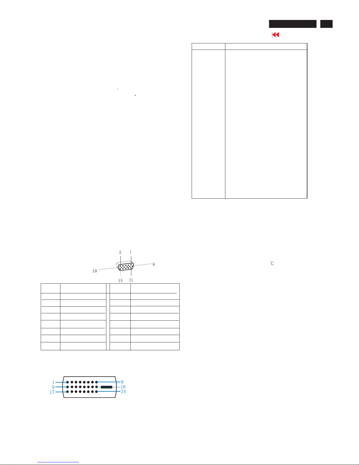
Pin Assignment
Input DVI-D connector pin
Red video input
Green video input
Blue video input
GND
Cable detect
Red video GND
Green video GND
Blue video GND
DDC +3.3V OR +5V
GND
GND
Serial data line (SDA)
H-sync
V-sync
Data clock line (SCL)
7
8
6
5
4
3
2
1
9
10
11
12
13
14
15
Pin No.
Pin No.
Assignment
Assignment
Pin No. Description
1
T.M.D.S. data2-
2
T.M.D.S. data2+
3
T.M.D.S. data2 shield
4
No Connect
5
No Connect
6
DDC clock
7
DDC data
8
No Connect
9
T.M.D.S. data1-
10
T.M.D.S. data1+
11
T.M.D.S. data1 shield
12
No Connect
13
No Connect
14
+5V Power
15
Ground (for +5V) - Cable detect
16
Hot plug detect
17
T.M.D.S. data0-
18
T.M.D.S. data0+
19
T.M.D.S. data0 shield
20
No Connect
21
No Connect
22
T.M.D.S clock shield
23
T.M.D.S. clock+
24
T.M.D.S. clock-
LCD panel
Type NR. : LM201U04 (LG.PHILIPS)
Outside dimensions : 432.0(w)*331.5(h)*25(d) (Typ) mm
Pitch ( mm ) : 0.255 (per one triad) x 0.-255mm
Color pixel arrangement : RGB vertical stripes
Display surface : low reflection, antiglare with hard coating
Color depth : 16777216 colors (8 bits)
Backlight : Six CCFL
s
Active area(WxH) : 408x306mm (20.1
diagonal)
View angle : Horizontal & Vertical 160 degree (CR>=10)
Contrast ratio : 400:1
White luminance : Panel original color >200nits (min), 250
nits (Typ.)
Main voltage : AC 90 - 135 Vrms and 170 - 264 Vrms,
50/60 ± 2Hz
Power cord length : 1.8M
Power cord type : 3 lead with earth plug
Power indicator : LED (ON: blue, Standby: amber, NEW
MODE: flashing blue twice per second
before user adjust and save it.).
Auto power saving : EPA, Nutek, VESA DPMS
Horizontal scan : 30 - 97 KHz
Vertical scan : 56 - 85 Hz
Horizontal scanning
Sync polarity :Positive or negative
Scanning frequency :30 - 93 K Hz
Vertical scanning
Sync polarity :Positive or negative
Scanning frequency :56 - 85 Hz
Mechanical
Pedestal : Detachable
Tilt angle : -5° to 35°
Swivel rotation : ±68°
Environmental conditions
Operating
-Temperature C : 0°cto35°c
-Humidity : 80 % max
-Altitude : 0-3658m
-Air pressure : 600-1100mBAR
Storage
-Temperature C : -30 to 60°
-Humidity : 85% max ( < 40
)
-Altitude : 0-12192m
-Air pressure : 300-1100mBAR
Note: recommend at 5°cto35°C, Humidity less than 60 %
4
Go to cover page
Installation
200P6 LCD
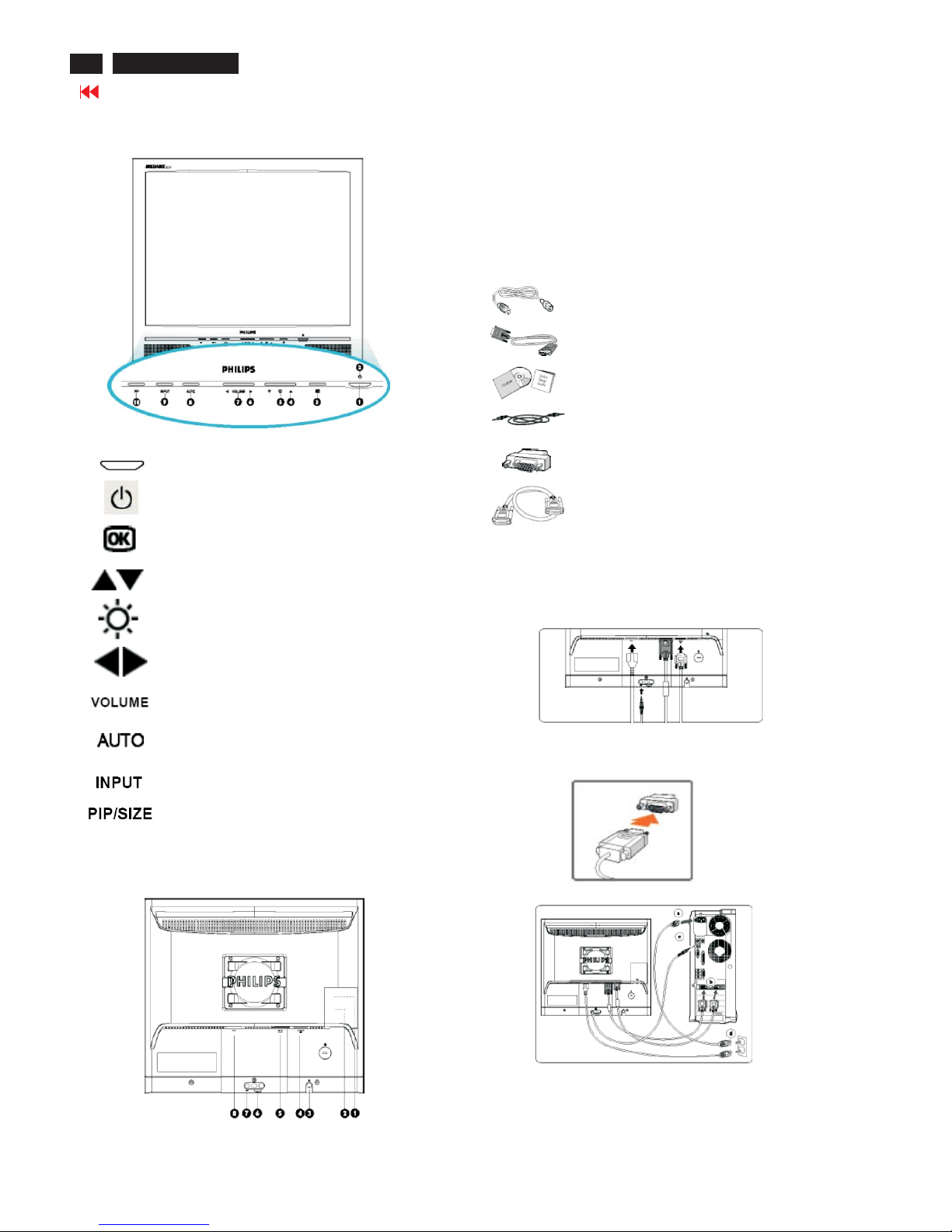
Front View
Rear View
Power cord
VGA signal cable
EDFU pack
PC audio cable (lime)
Mac adaptor (optional)
DVI-D cable
Accessory Pack
Item Description
Connecting to Your PC
1
2
3
4
5
6
7
8
9
10
To switch monitor's power On and Off
Power LED
To access OSD menu
To adjust the OSD
To adjust brightness of the display
To adjust the OSD
To adjust speaker volume
Automatically adjust the horizontal position,
vertical position, phase and clock setting
Signal input selection
Activate PIP (Picture in Picture) window (200P6I)
or adjust screen size (200P6E)
1 CVBS video input (for video model 200P6I- only )
2 S-Video input (for video model 200P6I- only )
3 Earphone jack
4 VGA input
5 DVI-I input
6 Audio R/L input
7 PC audio input
8 AC power input
Connect the power cord, DVI and audio cable to the back of the
monitor firmly. (Philips has pre-connected VGA cable for the first
installation.)
Notes:If you use an Apple Macintosh , you need to connect the
special Mac adapter to one end of the monitor signal cable.
TM
Connect the cables to the back of your computer by following these
steps:
(a) Turn off your computer and unplug its power cord.
(b) Connect the VGAor DVI cable to the video connector.
(c) Connect the audio cable.
5
Go to cover page
200P6 LCD
Installation
(d) Plug the power cord of the computer and the monitor into a
nearby outlet.
(e) Turn on your computer and monitor. If the monitor displays an
image, installation is complete.
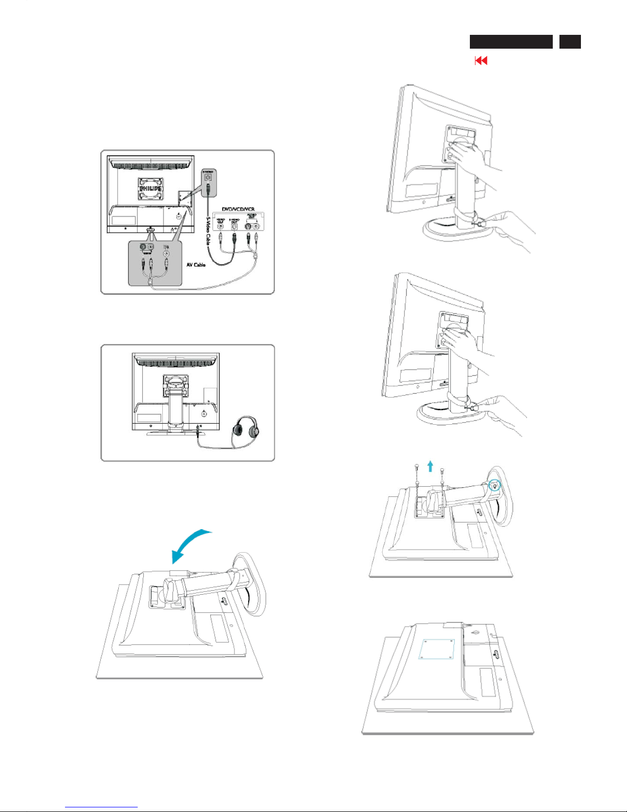
Connect to DVD/VCR/VCD
Connect to Earphone
VESA Standard Mounting
1) Place monitor face down on a surface.
2) Remove the cable cover
3) Remove the base cover.
4) Unscrew the 5 screws at the base.
5) VESA mounting holes
6
Go to cover page
200P6 LCD
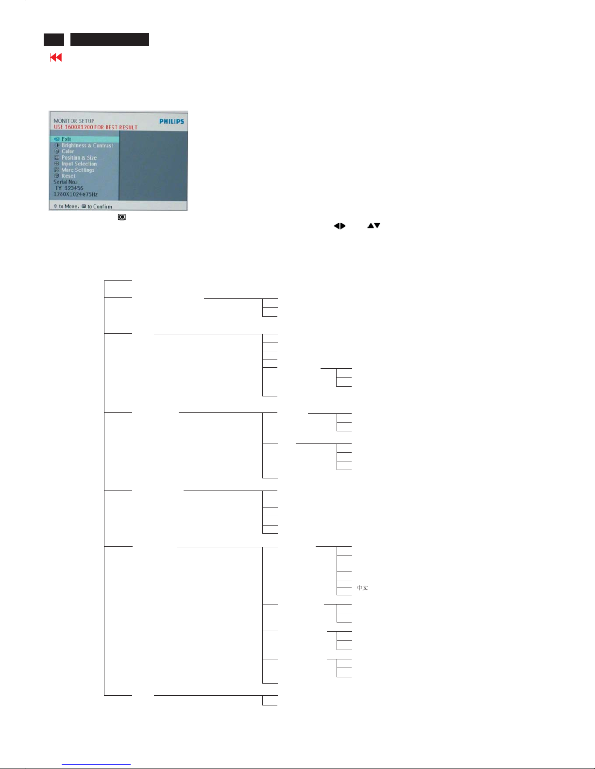
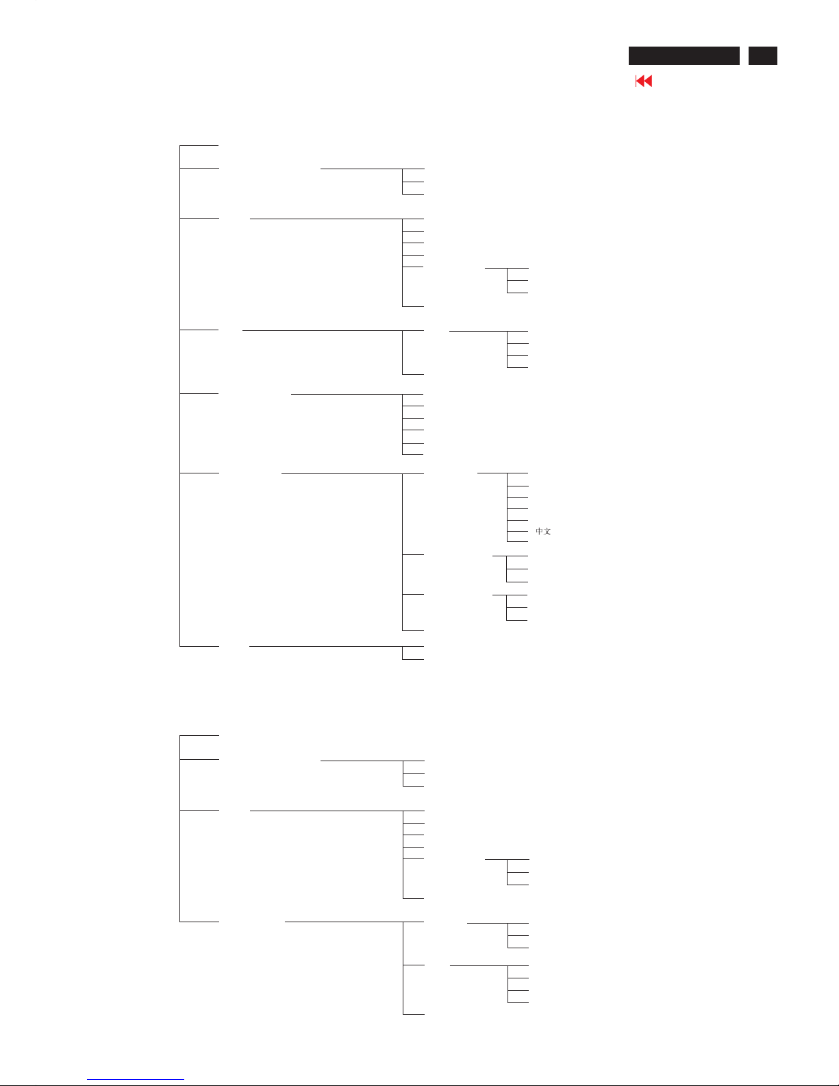
On Screen Display
Description of the On Screen Display
This is a feature in all Philips LCD monitors. It allows an end user to adjust screen performance of the monitors directly through an
on-screen instruction window. The user interface provides userfriendliness and ease-of-use when operating the monitor.
Basic and simple instruction on the control keys.
PC analog signal(VGA&DVI-A) input mode
Main Menu Sub Menu
When you press the button on the front control of your monitor, the On-Screen Display (OSD) Main Controls window will pop up and
you can then start making adjustments to your monitor's various features. Use the or the keys to make your adjustments.
Exit
Brightness&Contrast
Brightness
Contrast
Back
Color
Original Color
9300K
6500K
sRGB
User Define
Red
Green
Blue
Back
Position&Size
Position
Horizontal
Vertical
Back
Size
Full Screen
Native Mode
Fill With Aspect
Back
Back
Input Selection
Analog(D-Sub)
Analog(DVI-A)
Digital(DVI-D)
CVBS
S-Video
Back
More Setting
Language
ENGLISH
ESPANOL
FRANCALS
DEUTSCH
ITALIANO
Back
Phase/Clock
Phase
Clock
Back
OSD Settings
Horizontal
Vertial
Back
Audio Options
Stand-alone
Mute
Back
Back
Reset
No
Yes
7
Go to cover page
200P6 LCD
On Screen Display
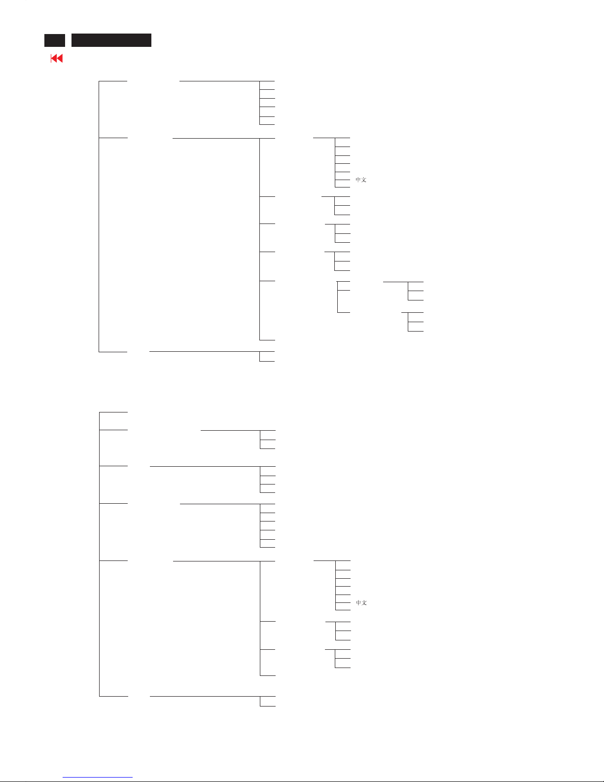
PC digital signal(DVI-D) input mode only
Main Menu Sub Menu
Exit
Brightness&Contrast
Brightness
Contrast
Back
Color
Original Color
9300K
6500K
sRGB
User Define
Red
Green
Blue
Back
Size
Size
Full Screen
Native Mode
Fill With Aspect
Back
Back
Input Selection
Analog(D-Sub)
Analog(DVI-A)
Digital(DVI-D)
CVBS
S-Video
Back
More Setting
Language
ENGLISH
ESPANOL
FRANCALS
DEUTSCH
ITALIANO
Back
OSD Settings
Horizontal
Vertial
Back
Audio Options
Stand-alone
Mute
Back
Back
Reset
No
Yes
PIP mode only
Main Menu Sub Menu
Exit
Brightness&Contrast
Brightness
Contrast
Back
Color
Original Color
9300K
6500K
sRGB
User Define
Red
Green
Blue
Back
Position&Size
Position
Horizontal
Vertical
Back
Size
Full Screen
Native Mode
Fill With Aspect
Back
Back
8
Go to cover page
200P6 LCD
On Screen Display
Input Selection
Analog(D-Sub)
Analog(DVI-A)
Digital(DVI-D)
CVBS
S-Video
Back
More Setting
Language
ENGLISH
ESPANOL
FRANCALS
DEUTSCH
ITALIANO
Back
Phase/Clock
Phase
Clock
Back
OSD Settings
Horizontal
Vertial
Back
Audio Options
Stand-alone
Mute
Back
Back
Reset
No
Yes
Picture In Picture
Horizontal
Vertial
Back
Position
Audio Source
Audio 1(PC)
Audio 2(Video)
Back
Video Signal input mode only
Main Menu Sub Menu
Exit
Brightness&Contrast
Brightness
Contrast
Back
Color
Sharpness
Saturation
Tint
Back
Input Selection
Analog(D-Sub)
Analog(DVI-A)
Digital(DVI-D)
CVBS
S-Video
Back
More Setting
Language
ENGLISH
ESPANOL
FRANCALS
DEUTSCH
ITALIANO
Back
OSD Settings
Horizontal
Vertial
Back
Audio Options
Stand-alone
Mute
Back
Back
Reset
No
Yes

9
Go to cover page
200P6 LCD
Lock/Unlock,Aging,Factory Mode
Front Control
To Lock/Unlock OSD FUNCTION(User Mode)
The OSD function can be locked by pressing"OK"button(1) for more
than 10 seconds, the screen shows following windows for 4 seconds.
Everytime when you press"OK" button, this message
appears on the screen automatically.
ATTENTION SIGNAL
OSD MAIN CONTROLS
LOCKED
Unlock OSD function
Unlocked OSD function can be released by pressing "OK" button for
more than 10 seconds again.
ATTENTION SIGNAL
OSD MAIN CONTROLS
UNLOCKED
After 10 seconds,
bring up:
----------
---------repeatly
Connect Signal cable again=> go back to normal display
After 10 seconds,
bring up:
After 5 seconds,
bring up:
Access Aging Mode
Step1:D
Step 2 : [Push "AUTO"&"OK"buttons
at the same time and hold them]+[Press power " " button untill comes
out " AGING screen"] => then release all buttons.
Bring up:
isconnect Interface Cable between Monitor and PC.
Turn off LCD monitor.Then
Access Factory Mode
1). Turn off monitor.
2).
3).Press "OK" button, wait until the OSD menu with Characters
"HUDSON6 200P6 V0.02 050104 With VIDEO" (below OSD
menu) come on the Screen of the monitor.
[Push "AUTO" & "OK" buttons at the same time and hold them]
+[Press "power" button untill comes out "Windows screen" ]
=> then release all buttons
Factory Mode indicator
Factory Menu
Cursor can move on gray color area
Hot key function: by pressing " UP " and " DOWN " key
Simultaneously at User Mode (or Factory Mode)
(PS: The OffsetRGBfunction can be used on reduce or eliminate
snowy noise on the background when the resolution of video signal
is 1280*1024 vertical 60Hz. Slightly increase or decrease the value
until snowy noise completely disappear.
ATTENTION
AGING...
ATTENTION
AGING...
ATTENTION
AGING...
ATTENTION
AGING...
ATTENTION
AGING...
ATTENTION
AGING...
10
Go to cover page
200P6 LCD
Philips Pixel Defect Policy
Philips' Flat Panel Monitors Pixel Defect Policy
Philips strives to deliver the highest quality products. We
use some of the industry's most advanced manufacturing
processes and practice stringent quality control. However,
pixel or sub pixel defects on the TFT LCD panels used in
flat panel monitors are sometimes unavoidable. No
manufacturer can guarantee that all panels will be free
from pixel defects, but Philips guarantees that any monitor
with an unacceptable number of defects will be repaired or
replaced under warranty. This notice explains the different
types of pixel defects and defines acceptable defect levels
for each type. In order to qualify for repair or replacement
under warranty, the number of pixel defects on a TFT LCD
panel must exceed these acceptable levels. For example,
no more than 0.0004% of the sub pixels on a 15" XGA
monitor may be defective. Furthermore, Philips sets even
higher quality standards for certain types or combinations
of pixel defects that are more noticeable than others. This
policy is valid worldwide.
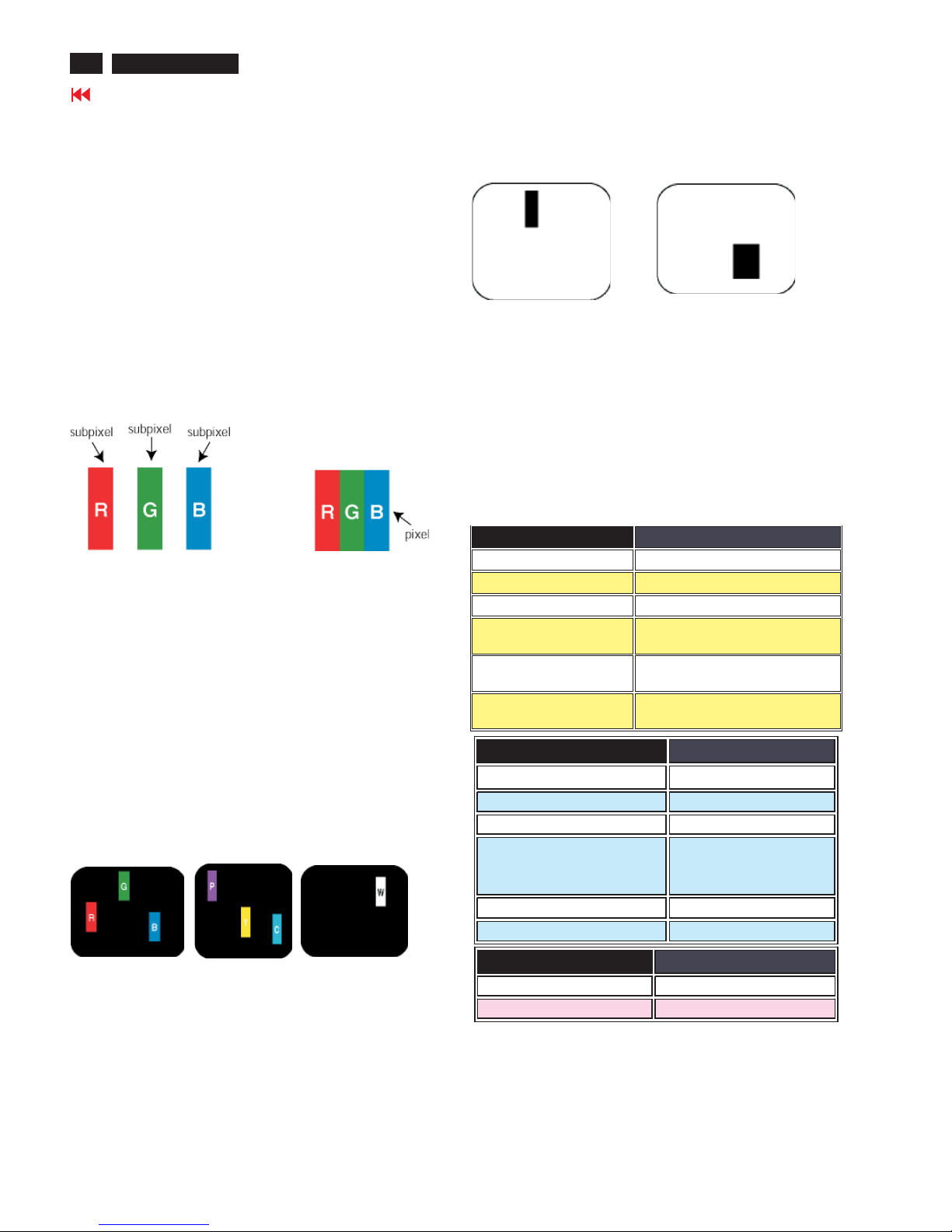
Pixels and Sub pixels
A pixel, or picture element, is composed of three sub pixels
in the primary colors of red, green and blue. Many pixels
together form an image. When all sub pixels of a pixel are lit,
the three colored sub pixels together appear as a single
white pixel. When all are dark, the three colored sub pixels
together appear as a single black pixel. Other combinations
of lit and dark sub pixels appear as single pixels of other
colors.
Types of Pixel Defects
Pixel and sub pixel defects appear on the screen in different
ways. There are two categories of pixel defects and several
types of sub pixel defects within each category. Bright dot
defects appear as pixels or sub pixels that are always lit or
'on'. These are the types of bright dot defects:
One lit red,
green or
blue sub pixel
Two adjacent lit
sub pixels:
- Red+ Blue =Purple
- Red+ Green =Yellow
- Green+ Blue =Cyan
(Light Blue)
Three adjacent lit
sub pixels
(one white pixel)
Black Dot Defects Black dot defects appear as pixels or sub
pixels that are always dark or 'off'. These are the types of black
dot defects:
One dark sub pixel Two or three adjacent dark sub pixels
Proximity of Pixel Defects
Because pixel and sub pixels defects of the same type that are
near to one another may be more noticeable, Philips also specifies
tolerances for the proximity of pixel defects.
Pixel Defect Tolerances
In order to qualify for repair or replacement due to pixel defects
during the warranty period, a TFT LCD panel in a Philips flat panel
monitor must have pixel or sub pixel defects exceeding the
tolerances listed in the following tables.
Note:
* 1 or 2 adjacent sub pixel defects = 1 dot defect
All Philips monitors are ISO13406-2 Compliant
TOTAL DOT DEFECTS ACCEPTABLE LEVEL
MODEL 200P6
Total bright or black dot defects of all types 5 or fewer
BRIGHT DOT DEFECTS ACCEPTABLE LEVEL
MODEL
200P6
1 lit subpixel
4 or fewer
2 adjacent lit subpixels
2 or fewer
3 adjacent lit subpixels (one white
pixel)
0
Distance between two bright dot
defects*
Total bright dot defects of all types
BLACK DOT DEFECTS ACCEPTABLE LEVEL
MODEL
200P6
1 dark subpixel 4 or fewer
2 adjacent dark subpixels 2 or fewer
3 adjacent dark subpixels 0
Distance between two black dot defects* 15 mm or more
Total black dot defects of all types 4 or fewer
15mm or more
4 or fewer
11
Go to cover page
200P6 LCD
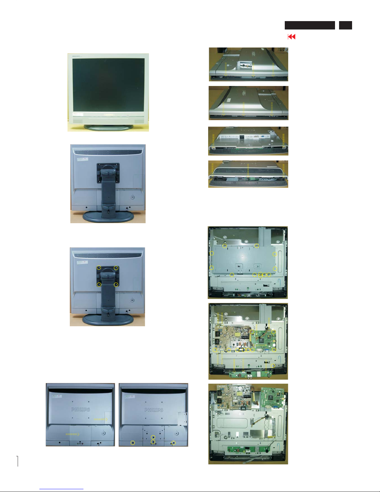
Mechanical Instruction
Front view
Back view
Step 1. Remove the stand.
Unscrew the 4 screws as Fig.3
Fig.3
Fig.2
Fig.1
Fig.7
Fig.8
Fig.4
Fig.5
Fig.6
Fig.9
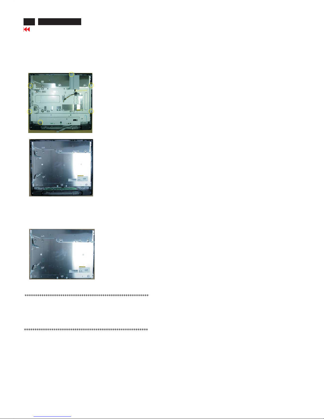
Step 2: Remove the Back Cover Assy
a. Remove the COVER-VIDEO and COSMETIC BACK COVER in
Fig.4 .
b. Unscrew 4 screws as shown in Fig.5.
c. Open 3 clicks on right and left side as shown in Fig.6 and Fig.7.
d. Open 2 clicks on bottom side as shown in Fig.8.
e. Open 3 clicks on top side as shown in Fig.9.
f . Remove the CASE-AUDIO and BACK COVER ASSY in Fig.10.
Fig.10
Fig.11
Step 3. Remove the Scaler ,Audio and Power board.
a. Unscrew
b. Unscrew the 10 screws and disconnect the 10 cables as Fig. 11.
c.
the 12 screws to remove the METAL COVER ASSY
as Fig.10.
Remove as Fig. 12.the Scaler ,Audio and Power board
Fig.12
Mechanical Instruction
Go to cover page
12
200P6 LCD
In warranty, it is not allowed to disassembly the LCD panel, even the
backlight unit defect.
Out of warranty, the replacment of backlight unit is a correct way
when the defect is cused by backlight (CCFL,Lamp).
Fig. 13
Step 3. Remove the LCD panel.
a. Unscrew
b. Remove the BRACKET-HOLD DOWN and FRAME+WIRE
ASSY as Fig. 14.
c. Remove the LCD panel as Fig.15.
the 6 screws and disconnect the 1 cables as Fig. 13.
LCD Panel
1050 823827718031 TFT-LCD MOD LM201U04-A3KC(Fig.15).
Fig. 14
Fig. 15
13
Go to cover page
200P6 LCD
Color Adjustment
Alignment procedure
1. Turn on the LCD monitor.
2.Turn on the Timing/pattern generator. See Fig.1
3. Preset LCD color Analyzer CA-110
-Remove the lens protective cover of probe CA-A30.
-Set measuring/viewing selector to measuring position for reset
analyzer.(zero calibration) as Fig.2
- Turn on the color analyzer (CA-110)
-Press 0-CAL button to starting reset analyzer.
Fig. 1
Fig. 2
Clear imageClear image
Measurement/viewing selectorMeasurement/viewing selector
Fig. 3
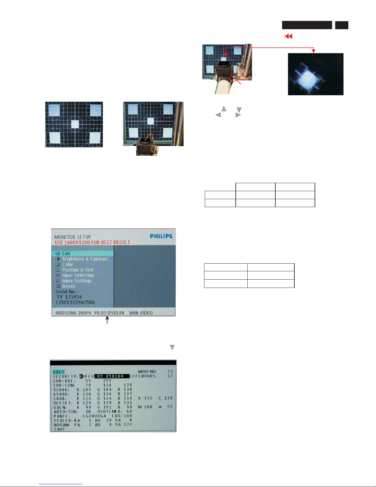
4). Press button, then select factory mode indicator by"OK" " "
button .Press"OK" button to bring up submenu windows as below:
Fig.5
Cover (black)Cover (black)
Measurement viewing selectorMeasurement viewing selector
Fig. 4
Fig. 2
5.Display
Press " " or " " button to select . Change the value
by " " or " " key until the X,Y co-ordinates as below
4. Access Factory Mode
1). Turn off monitor.
2).
3).Press "OK" button, wait until the OSD menu with Characters
"HUDSON6 200P6 V0.02 050104 With VIDEO" (below OSD
menu) come on the Screen of the monitor. as shown in Fig3.
[Push "AUTO" & "OK" buttons at the same time and hold them]
+[Press "power" button untill comes out "Windows screen" ]
=> then release all buttons
Factory Mode indicator
5.1 Auto color adjustment (B)
Apply a 1280x1024/60Hz signal with 64-gray levels pattern, set
brightness control at 100%, and contrast control at 50%.
Adjust the R. G. B offset, and gain to calibrate the color smoothly
and 64-gray level distinguishable. Check all factory pre-setting modes.
5.2 Adjustment of WHITE-D (B)
Apply a 1280*1024 / 60Hz signal with white pattern, set brightness control
at 100%, and contrast control at 50%. Adjust the R, G, B Sub-Gain, for
he screen center, the 1931 CIE chromaticity (X, Y) co-ordinates shall be;
Use Minolta CA-110 for colour coordinates and luminance check.
Luminance is > 200 Nits in the center of the screen when brightness at
100% and contrast set to 100%.
5.3 Adjustment of sRGB
Apply a 1280*1024 / 60Hz signal with white pattern, set brightness control
at 100%, and contrast control at 50%. Adjust the R, G, B Sub-Gain, for
the screen center, the 1931 CIE chromaticity (X, Y) co-ordinates shall be;
sRGB
x(center) 0.313 ± 0.020
y(center) 0.329 ± 0.020
5.4 Factory Preset (B):
After finished all the adjustment, set:
OSD Default Setting:
Brightness : 100%
Contrast : 50%
Adjust size : Full screen
Language : English
Colour : 6500K for IMAGE MANAGEMENT
OSD position : middle of the LCD screen
Input Selection: Default as PC VGA (D-sub)
PIP position : bottom right corner
PIP audio source: PC Audio
PIP video source: CVBS
Volume: 50%
5.5 In Factory mode default setting :
SECURITY : OFF
SUB-BRI : 0 255 (Fix)
SUB-CON : 78 128 178 (Fix)
9300°K 6500°K
x (center) 0.283 ± 0.020 0.313 ± 0.020
y (center) 0.297 ± 0.020 0.329 ± 0.020
14
Go to cover page
200P6 LCD
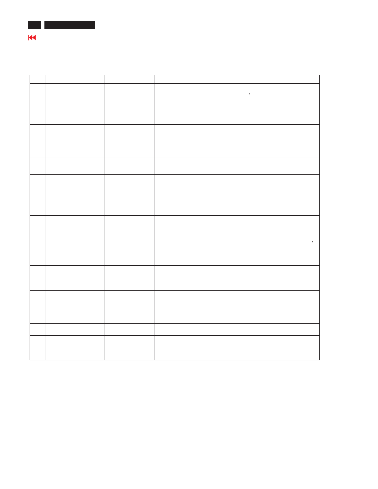
Warning Message
Item Attention Signals Display Time Condition
1 CANNOT DISPLAY THIS
VIDEO MODE, CHANGE
COMPUTER DISPLAY
INPUT TO 1600X1200@
60HZ
30 mins This warning appears when the input signal from your computer is not in a
standard video mode or is out of the monitor
s scanning range. After 30
mins, monitor enters sleeping mode.
2 NO VIDEO INPUT 30 mins This message appears when there is no signal input but with cable while AC
or DC power on. After 30 mins, monitor enters sleeping mode.
3 CHECK CABLE
CONNECTION
30 mins This message appears when a signal cable is disconnected while monitor is
working. After 30 mins, monitor enters sleeping mode.
4 ENTERING SLEEP
MODE
3 secs This message appears when monitor is about to enter power saving mode.
5 WAITING FOR
AUTOMATIC
ADJUSTMENT
till auto adjustment
finished
This message is displayed when the auto adjustment button is pressed. It
disappears when automatic adjustments are completed.
6 USE 1600X 14 FOR
BEST RESULT
On top of OSD main
menu
The message will show up at the top of the OSD main menu in red color
when the input resolution is not the 1280x1024.
7 OSD MAIN CONTROLS
LOCKED
3 secs / or Till "OSD
MAIN CONTROLS
UNLOCKED" appear
This message will appear 3 seconds to indicate the OSD MAIN CONTROLS
status when to lock or un-lock it by pressing "MENU(OK) " button for more
than 10 seconds while there is video input from PC. This function provides
the alternative that user can lock all the OSD main control in case user don
t want the FOS performance setting to be changed, for instance, during
commercial exhibition.
8 OSD MAIN CONTROLS
UNLOCKED
3 secs This message will appear 3 seconds to indicate the OSD MAIN CONTROLS
status when to un-lock it by pressing "MENU (OK) " button for more than 10
seconds while there is video input from PC.
9 the window of OSD
"MONITOR SETUP "
60 secs This message will appear when the "OK" button is pressed.
10 the window of
"BRIGHTNESS"
60 secs This message will appear when the BRIGHTNESS button is pressed.
11 the window of "VOLUME" 60 secs This message will appear when the VOLUME button is pressed.
12 "SELECTED INPUT NOT
AVAILABLE"
3 secs This message will appear 3 seconds to indicate the SIGNAL SOURCE status
when change the signal source but it is not found while there is video input
from PC.
Warning message table
15
Go to cover page
200P6 LCD
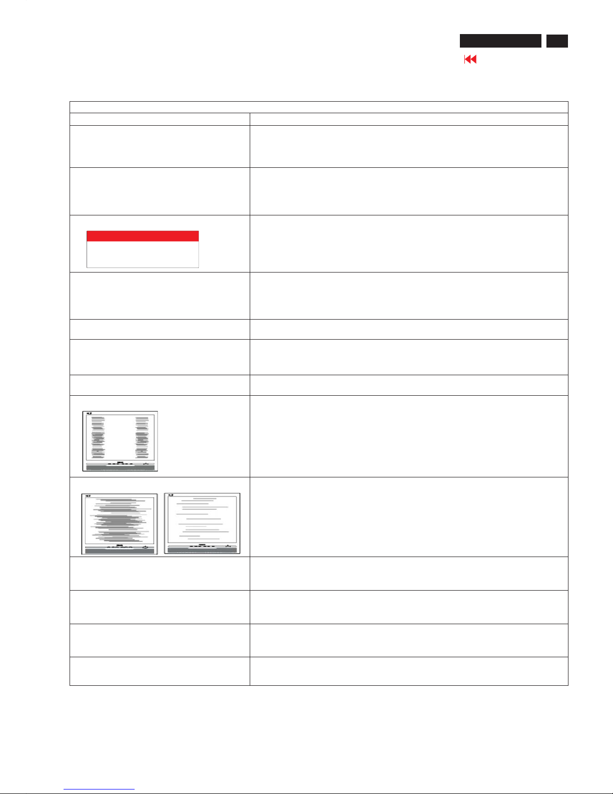
Troubleshooting
Common Problems
Having this problem
Check these items
No Picture
(Power LED not lit)
1.Make sure the power cord is plugged into the power outlet and into the back of the
monitor.
2.First, ensure that the power button on the front of the monitor is in the OFF position,
then press it to the ON position.
No Picture
(Power LED is amber or yellow)
1.Make sure the computer is turned on.
2. Make sure the signal cable is properly connected to your computer.
3.Check to see if the monitor cable has bent pins.
4.The Energy Saving feature may be activated
Screen says
1. Make sure the monitor cable is properly connected to your computer. (Also refer
to the Quick Set-Up Guide).
2.Check to see if the monitor cable has bent pins.
3. Make sure the computer is turned on.
AUTO button not working properly
1.The Auto Function is designed for use on standard Macintosh or IBM-compatible
PCs running Microsoft Windows.
2. It may not work properly if using nonstandard PC or video card.
Imaging Problems
Display position is incorrect
1.Press the Auto button.
2. Adjust the image position using the Horizontal Position and/or Vertical
Position in OSD Main Controls.
Image vibrates on the screen
Check that the signal cable is properly connected to the graphics board or PC.
Vertical flicker appears
1. Press the Auto button.
2. Eliminate the vertical bars using the More Settings of Phase/Clock in OSD Main
Controls.
Horizontal flicker appears
1. Press the Auto button.
2. Eliminate the vertical bars using the More Settings of Phase/Clock in OSD Main
Controls.
The screen is too bright or too dark
Adjust the contrast and brightness on OSD Main Controls. (The backlight of the
LCD monitor has a fixed life span. When the screen becomes dark or begins to
flicker, please contact your dealer).
An after-image appears
If an image remains on the screen for an extended period of time, it may be
imprinted in the screen and leave an afterimage. This usually disappears after a
few hours.
An after-image remains after the power
has been turned off.
This is characteristic of liquid crystal and is not caused by a malfunction or
deterioration of the liquid crystal. The after-image will disappear after a peroid
of time.
Green, red, blue, dark, and white dots
Remains
The remaining dots are normal characteristic of the liquid crystal used in
today's technology.
ATTENTION
NO VIDEO INPUT
16
Go to cover page
200P6 LCD
Electrical Instructions
1. General points
1.1 During the test and measuring, supply a distortion free AC mains voltage to the apparatus via an isolated transformer with low internal
resistance.
1.2 All measurements mentioned hereafter are carried out at a normal mains voltage (90 - 132 VAC for USA version, 195 -264 VAC for EUROPEAN
version, or 90 - 264 VAC for the model with full range power supply, unless otherwise stated.)
1.3 All voltages are to be measured or applied with respect to ground,unless otherwise stated.
Note: don't use heat-sink as ground.
1.4 The test has to be done on a complete set including LCD panel in a room with temperature of 25 +/- 5 degree C.
1.5 All values mentioned in these test instruction are only applicable of a well aligned apparatus, with correct signal.
1.6 The letters symbols (B) and (S) placed behind the test instruction denotes
(B): carried out 100% inspection at assembly line
(S): carried out test by sampling
1.7 The white balance (color temperature), has to be tested in subdued lighted room.
1.8 Repetitive power on/ off cycle are allowed. The image can be displayed after 8 sec.
1.9 All optical characteristics (including WHITE-D, Brightness, and so on) are determined according to panel specification after warming up
approximate 30 minutes that brightness stability is optimal, and follow strictly after panel specification.
2. Input signal
Signal type
2.1.1 Analogue Video: 0.7 Vp-p linear, positive polarity
Sync. : TTL level, separate, positive or negative polarity
Signal source: pattern generator format as attachment. Reference generator : QuantumData 802G/ 802R or Chroma 2237
2.1.2 Digital Video :600mVp-p TMDS Signal
2.1.3 CVBS Video :1Vp-p,75 Ohm
2.1.4 S-Video :Y-1Vp-p,75 Ohm C-0.3Vp-p,75 Ohm
2.1.5 Audio Signal : For S-terminal/ CVBS is L/R audio input PC line in
2.2 Input signal mode
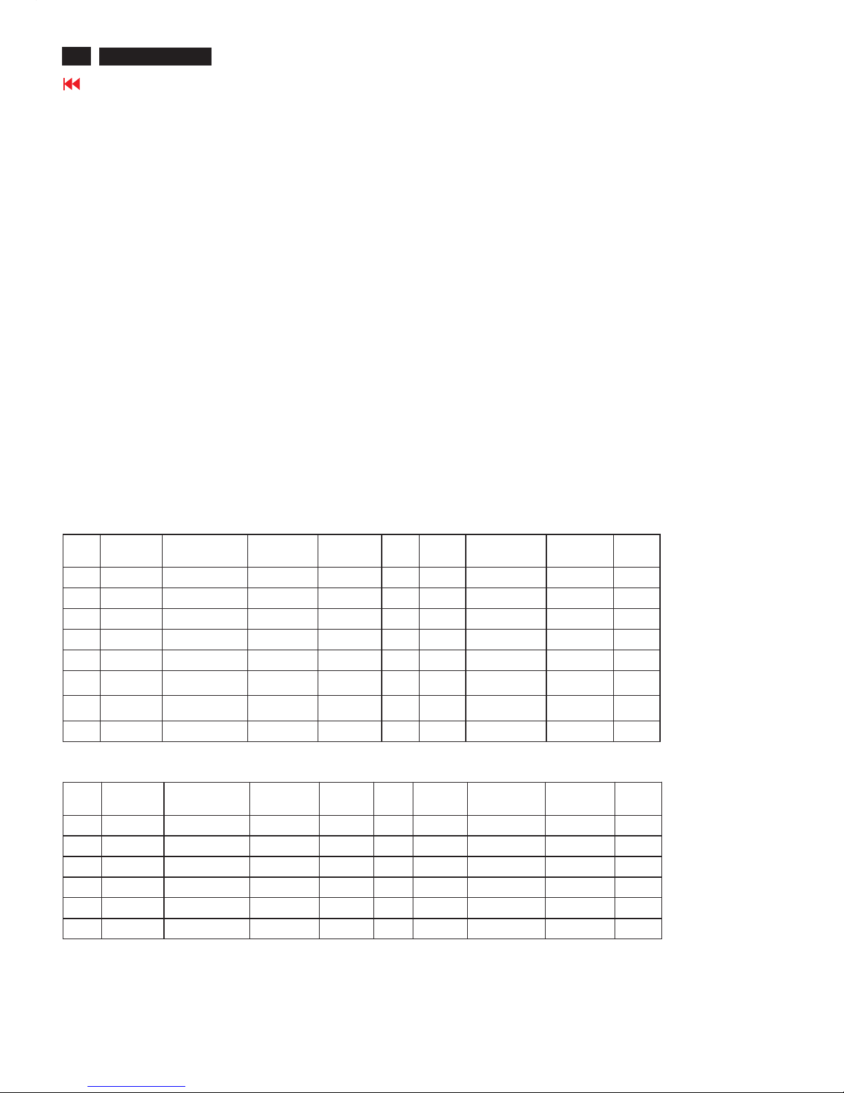
(1) Factory Preset Modes (15modes)
Item H.Freq.
(KHz)
Mode Resolution V.Freq.
(Hz)
Item H.Freq
.(KHz)
Mode Resolution V.Freq
.(Hz)
1 31.469 IBM VGA 10H 640x350 70.086 9 60.023 VESA 1024x768 75.029
2 31.469 IBM VGA 3H 720x400 70.087 10 68.700 MACINTOSH 1152x870 75.000
3 31.469 IBM VGA 12H 640x480 59.940 11 63.981 VESA 1280x1024 60.020
4 37.500 VESA 640x480 75.000 12 79.976 VESA 1280x1024 75.025
5 35.156 VESA 800x600 56.250 13 75.0 VESA 1600x1200 60
6 37.879 VESA 800x600 60.317 14 33.75 HDTV 1080i (D-
sub only)
60
7 46.875 VESA 800x600 75.000 15 45.0 HDTV 720p (D-
sub only)
60
8 48.363 VESA 1024x768 60.004
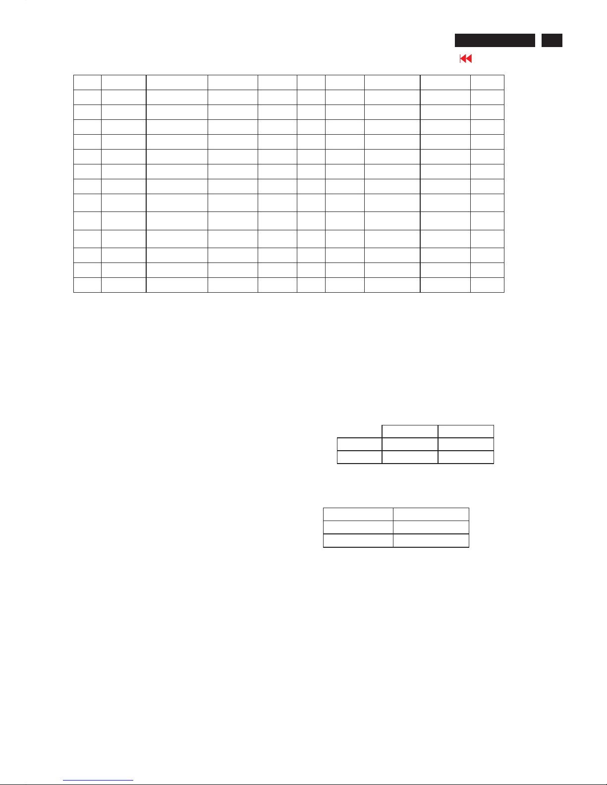
(2) Preset Modes (37modes)
Item H.Freq.
(KHz)
Mode Resolution V.Freq.
(Hz)
Item H.Freq.
(KHz)
Mode Resolution V.Freq
.(Hz)
1 31.469 IBM VGA 10H 640x350 70.086 21 67.500 VESA 1152x864 75.000
2 31.469 IBM VGA 3H 720x400 70.087 22 68.700 MACINTOSH 1152x870 75.000
3 31.469 IBM VGA 12H 640x480 59.940 23 61.845 SUN WS 1152x900 66.004
4 35.000 MACINTOSH 640x480 67.000 24 71.810 SUN WS 1152x900 76.150
5 37.861 VESA 640x480 72.809 25 60.000 VESA 1280x960 60.000
6 37.500 VESA 640x480 75.000 26 75.000 VESA 1280x960 75.000
17
Go to cover page
200P6 LCD
Electrical Instructions
7 43.269 VESA 640x480 85.008 27 85.939 VESA 1280x960 85.002
8 35.156 VESA 800x600 56.250 28 63.981 VESA 1280x1024 60.020
9 37.879 VESA 800x600 60.317 29 71.691 SUN WS 1280x1024 67.189
10 48.077 VESA 800x600 72.188 30 76.000 DOS/V 1280x1024 72.000
11 46.875 VESA 800x600 75.000 31 79.976 VESA 1280x1024 75.025
12 53.674 VESA 800x600 85.061 32 81.130 SUN WS 1280x1024 76.110
13 49.700 MACINTOSH 832x624 75.000 33 91.1 VESA 1280x1024 85
14 48.363 VESA 1024x768 60.004 34 75.0 VESA 1600x1200 60
15 56.476 VESA 1024x768 70.069 35 31.45 HDTV 480p (D-
sub only)
60
16 60.023 VESA 1024x768 75.029 36 33.75 HDTV 1080i (D-
sub only)
60
17 61.080 IBM XGA-2 1024x768 75.781 37 45.0 HDTV 720p (D-
sub only)
60
18 68.677 VESA 1024x768 84.997
19 54.1 1152x864 60
20 63.851 VESA 1152x864 70.012
3. AC, DC power board
3.1 Setup the AC I/P at 90VAC, and 18V panel loading 0.25A, the voltage is 18V+/- 0.9V, inverter 18V loading 1.8A, the output voltage is
18V +/- 0.9V, 5V loading 1.2A, the DC output voltage is 5V +/-0.25VDC, 12V audio loading 0.6A, the output voltage is 12V + / - 0.6V. (B)
4. Display Adjustment
4.1 Access to factory mode (IIC) in auto-alignment system
The communication protocol switch to IIC .
4.2 Auto color adjustment (B)
Apply a 1280x1024/60Hz signal with 64-gray levels pattern, set brightness control at 100%, and contrast control at 50%.
Adjust the R. G. B offset, and gain to calibrate the color smoothly and 64-gray level distinguishable. Check all factory pre-setting modes.
4.3 Adjustment of WHITE-D (B)
Apply a 1280*1024 / 60Hz signal with white pattern, set brightness
control at 100%, and contrast control at 50%. Adjust the R, G, B
Sub-Gain, for the screen center, the 1931 CIE chromaticity (X, Y)
co-ordinates shall be;
Use Minolta CA-110 for colour coordinates and luminance check.
Luminance is > 200 Nits in the center of the screen when brightness at 100% and contrast set to 100%.
4.4 Adjustment of sRGB
Apply a 1280*1024 / 60Hz signal with white pattern, set brightness
control at 100%, and contrast control at 50%. Adjust the R, G, B
Sub-Gain, for the screen center, the 1931 CIE chromaticity (X, Y)
co-ordinates shall be;
4.5 Factory Preset (B):
After finished all the adjustment, set:
4.5.1 OSD Default Setting:
Brightness: 100% Input Selection: Default as PC VGA (D-sub)
Contrast: 50% PIP position: bottom right corner
Adjust size: Full screen PIP audio source: PC Audio
Language: English PIP video source: CVBS
Colour: 6500K for IMAGE MANAGEMENT Volume: 50%
OSD position: middle of the LCD screen
sRGB
x(center) 0.313 ± 0.020
y(center) 0.329 ± 0.020
9300°K 6500°K
x (center) 0.283 ± 0.020 0.313 ± 0.020
y (center) 0.297 ± 0.020 0.329 ± 0.020
4.5.2 In Factory mode default setting :
SECURITY : OFF
SUB-BRI : 0 255 (Fix)
SUB-CON : 78 128 178 (Fix)
18
Go to cover page
200P6 LCD
DDC Instructions
Pin No. Description
1 T.M.D.S. data2-
2 T.M.D.S. data2+
3 T.M.D.S. data2 shield
4 No Connect
5 No Connect
6 DDC clock
7 DDC data
8 No Connect
9 T.M.D.S. data1-
10 T.M.D.S. data1+
11 T.M.D.S. data1 shield
12 No Connect
13 No Connect
14 +5V Power
15 Ground (for +5V) - Cable detect
16 Hot plug detect
17 T.M.D.S. data0-
18 T.M.D.S. data0+
19 T.M.D.S. data0 shield
20 No Connect
21 No Connect
22 T.M.D.S clock shield
23 T.M.D.S. clock+
24 T.M.D.S. clock-
General
DDC Data Re-programming
In case the DDC data memory IC or main EEPROM which storage all
factory settings were replaced due to a defect, the serial numbers have
to be re-programmed "Analog DDC IC, Digital DDC IC & EEPROM".
It is advised to re-soldered DDC IC and main EEPROM from the old
board onto the new board if circuit board have been replaced, in this case
the DDC data does not need to be re-programmed.
Additional information
Additional information about DDC (Display Data Channel) may be
obtained from Video Electronics Standards Association (VESA).
Extended Display Identification Data(EDID) information may be also
obtained from VESA.
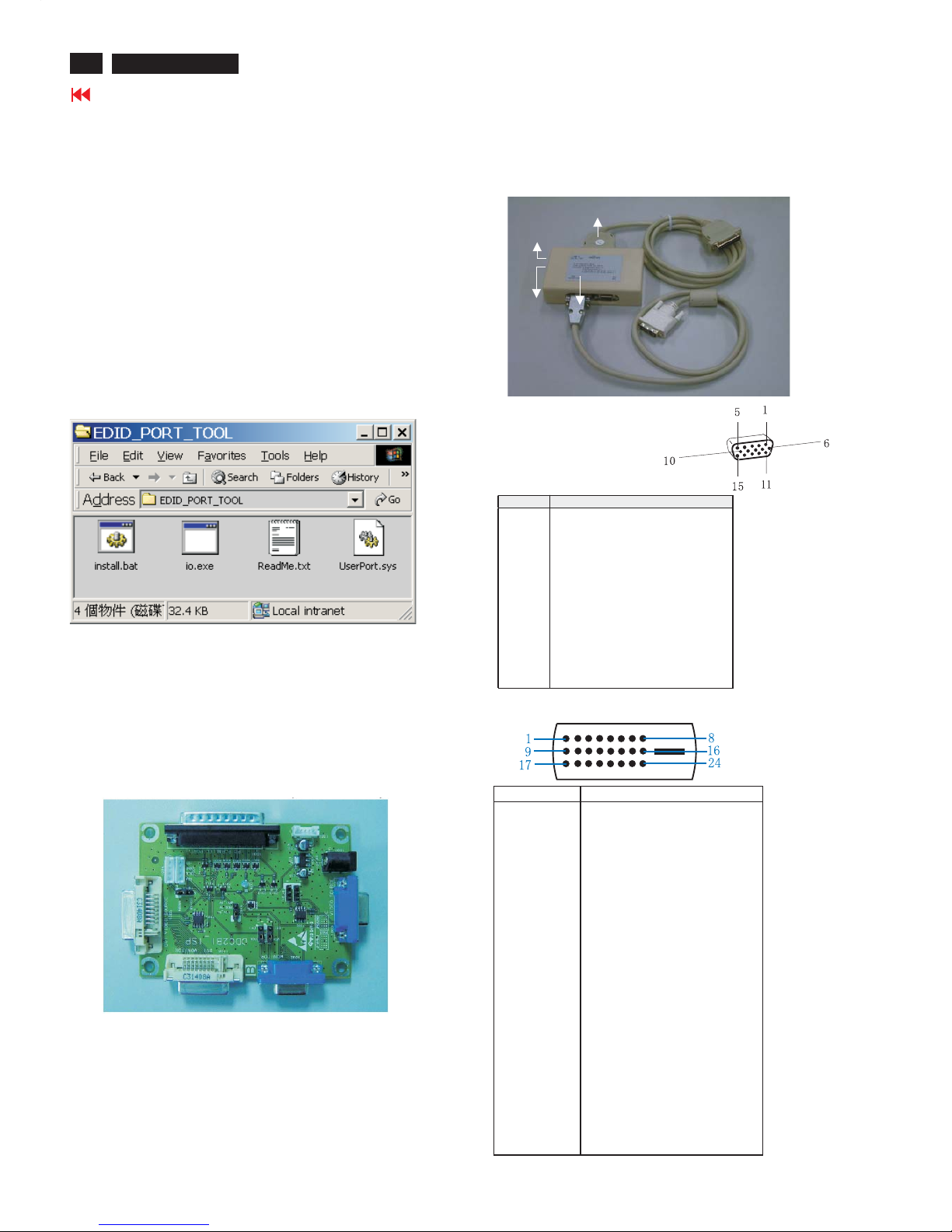
1. An i486 (or above) personal computer or compatible.
2. Microsoft operation system Windows 95/98 .
Y o Install the EDID_PORT_Tool under Win2000/XP . As
Fig. 1 .
A. Cody the "UserPort.sys" to C:\WINNT\system32\drivers(win2000)
C:\WINDOWS\system32\drivers(winXP)
B. Running " io.exe" everytime, Before you start to programming
edid data .
4. A/D Alignment kits (12NC: 3138 106 10396):
inclusion : a. Alignment box x1 (Fig. 2)
b. Printer cable x1
c. (D-Sub) to (D-Sub) cable x1
D. (D-Sub) to (DVI) cable x1
System and equipment requirements
ou have t
3. EDID46.EXE program
Fig. 1
Fig. 1
Fig. 2
To Monitor
D-sub/DVI cable
DC 8~12V
To Printer port
Power
indicator
Note: The alignment box has already build-in a batteries socket for
using batteries (8~12V) as power source. Pull out the socket by
remove four screws at the rear of box. Please do not forget that
remove batteries after programming. The energy of batteries can
only drive circuits for a short period of time.
PIN No. SIGNAL
1 Red video input
2 Green video input / sync on green
3 Blue video input
4GND
5 GND - Cable detect
6RedvideoGND
7 Green video GND
8 Blue video GND
9DDC+3.3Vor+5V
10 Logic GND
11 GND
12 Serial data line (SDA)
13 H-sync / H+V
14 V-sync
15 Data clock line (SCL)
Pin assignment
A. 15-pin D-Sub Connector
B. Input DVI -D Connector pin
Fig. 3
19
Go to cover page
DDC Instructions
200P6 LCD
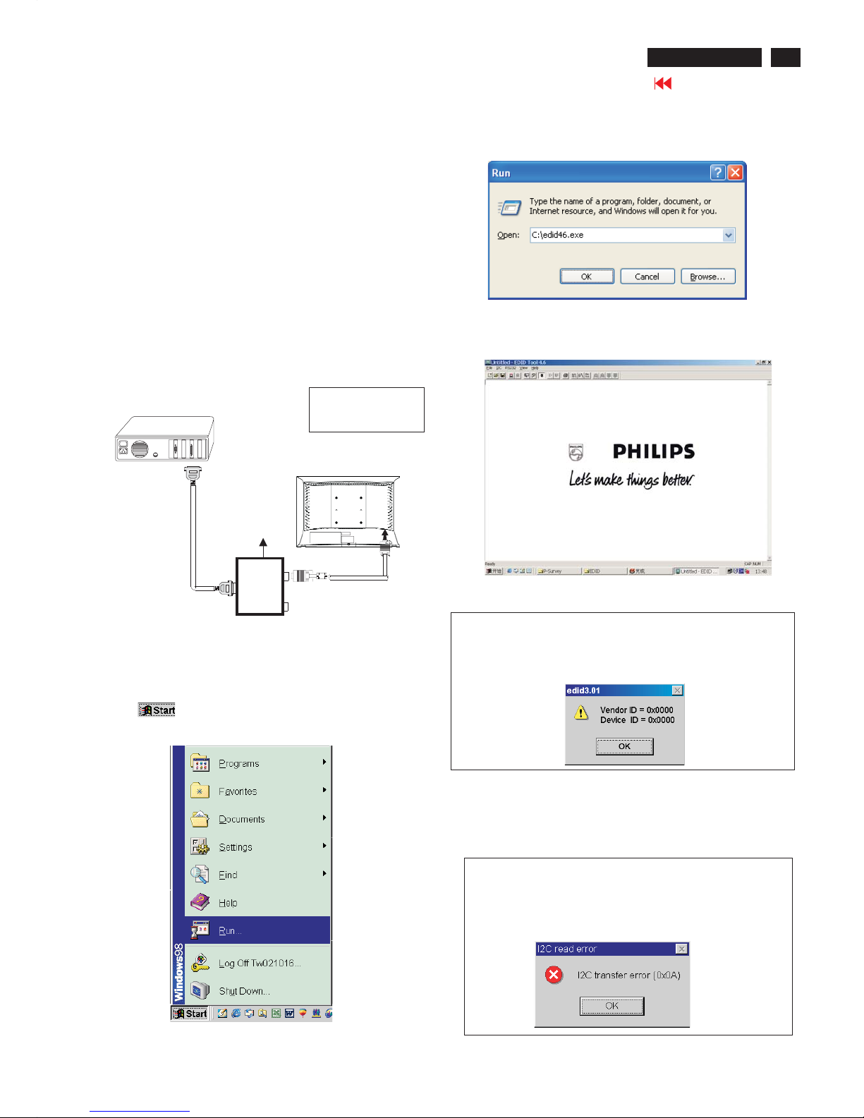
Step 3: Installation of EDID46.EXE
Method 1: Start on DDC program
Start Microsoft Windows.
1. The Program"EDID46.EXE" in service manual cd-rom be copyed to C:\ .
2. Click , choose Run at start menu of Windows as shown
In Fig. 5.
Fig. 5
4. Click OK button. The main menu appears (as shown in Fig. 7).
This is for initialize alignment box.
Fig. 7
Fig. 6
3. At the submenu, type the letter of your computer's hard disk drive
followed by :EDID46 (for example, C:\EDID46, as shown in Fig. 6).
Note 2: During the loading, EDID46 will verify the EDID data which just
loaded from monitor before proceed any further function, once
the data structure of EDID can not be recognized, the following
error message will appear on the screen as below. Please
confirm following steps to avoid this message.
1. The data structure of EDID was incorrect.
2. DDC IC that you are trying to load data is empty.
3. Wrong communication channel has set at configuration setup
windows.
4. Cables loosed or poor contact of connection.
1
Fig. 8
Note 1: If the connection is improper, you will see the following error
message (as shown in Fig. 8) before entering the main menu.
Meanwhile, the (read EDID) function will be disable. At this
time, please make sure all cables are connected correctly and
fixedly, and the procedure has been performed properly.
Fig. 9
Configuration and procedure
There is no Hardware DDC (DDC IC) anymore. Main EEPROM stores
all factory settings and DDC data (EDID code) which is also called
Software DDC. The following section describes the connection and
procedure for Software DDC application. The main EEPROM can be reprogrammed by enabling '' factory memory data write'' function on the
DDC program (EDID46.EXE).
Initialize alignment box
In order to avoid that monitor entering power saving mode due
to sync will cut off by alignment box, it is necessary to initialize
alignment box before running programming software
(EDID46.EXE). Following steps show you the procedures and
connection.
Step 1: Supply 8-12V DC power source to the Alignment box by
plugging a DC power cord .
Step 2: Connecting printer cable and D-Sub cable of monitor as Fig. 4
Fig. 4
PC
1= Power connector
2= D-SUB connector
To printer port (LTP1)
DC Power
8-12 V
Printer
Port
To
Monitor
To P C
1
2
----->
----->
20
Go to cover page
DDC Instructions
200P6 LCD
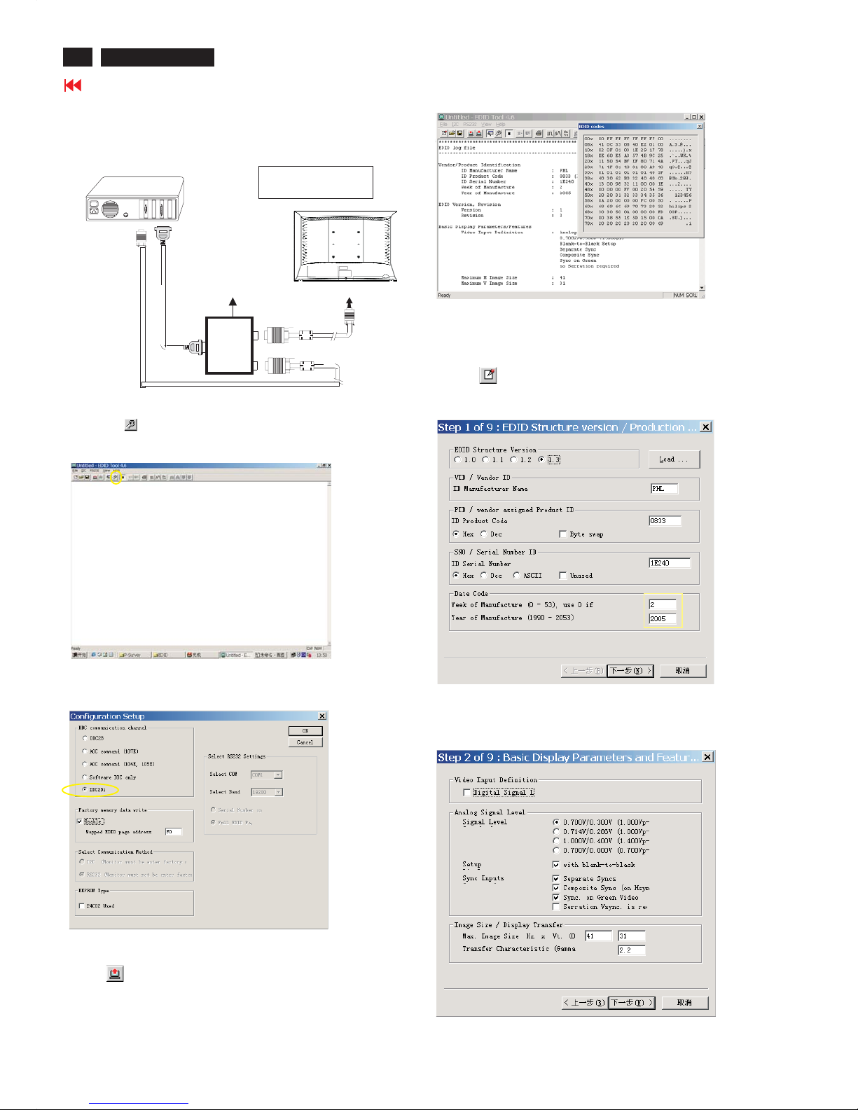
Step 3: Modify DDC data (verify EDID version, week,
year)
Click (new function) icon from the tool bar, bring up
Step 1 of 9 as shown in Fig. 14 .
EDID46 DDC application provides the function selection and
Step 4: Modify DDC data (Monitor Serial No.)
1. Click Next , bring up Fig. 15.
3. Click OK button to confirm your selection.
4. Click icon (Read EDID function) to read DDC EDID data from
monitor. The EDID codes will display on screen as shown in Fig. 13.
Fig. 15
2. Select the DDC2Bi as the communication channel.
As shown in Fig. 12.
Fig. 12
Fig. 13
Fig. 14
Select and fill out,
If necessary.
Re-programming Analog DDC IC
Step 1: After initialize alignment box, connecting all
cables and box as shown in Fig. 10.
Step 2: Read DDC data from monitor
1. Click icon as shown in Fig. 11 from the tool bar to bring up
the Channels "Configuration Setup" windows as shown in Fig. 11.
Fig. 10
1= Power connector
2= D-S UB connector
PC
To printer port (LTP1)
DC Power
8-12V
Printer
Port
To
Monitor
To P C
1
2
----->
----->
To PC Video port (D-sub)
Click this button
=====>
Fig. 11
21
Go to cover page
DDC Instructions
200P6 LCD
Fig. 21
Fig. 18
Fig. 19
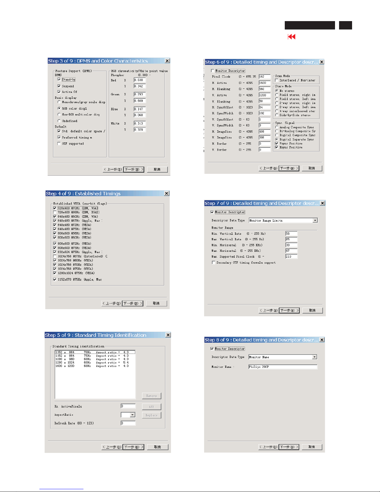
7. Click Next , bring up Fig. 21.
4. Click Next , bring up Fig.18.
5. Click Next , bring up Fig.19.
6. Click Next , bring up Fig. 20.
In this step, please confirm the Descriptor Data Type is
Monitor Range Limits, and all the items are same as below.
Fig. 20
2. Click Next , bring up Fig.16.
Fig. 16
Fig. 17
3. Click Next , bring up Fig.17.
22
Go to cover page
DDC Instructions
200P6 LCD
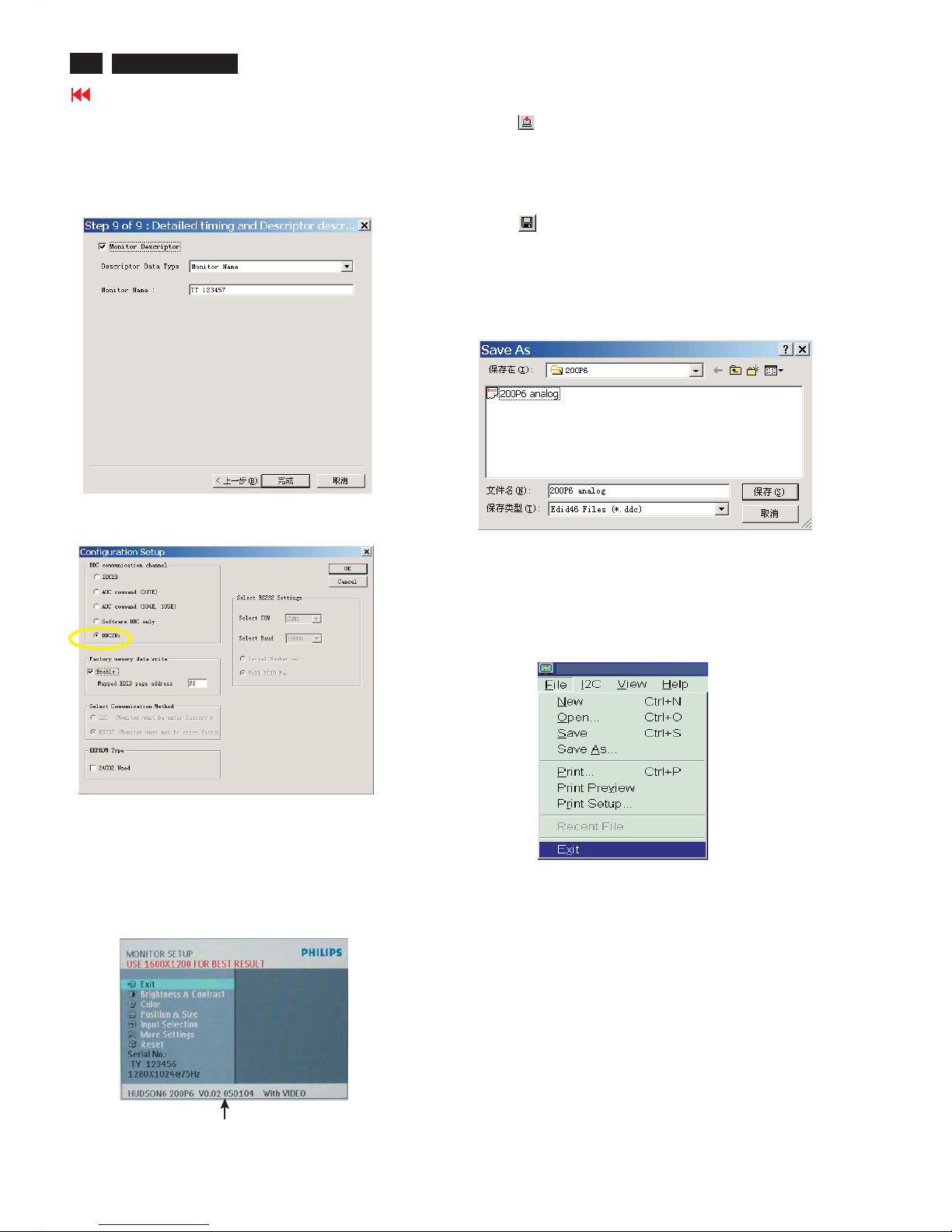
4). Click (Write EDID) icon from the tool bar to write DDC data. then
the EDID Tool will be closed automatically ,DDC data will be
finished Writing.
Fig. 24
3) Push Menu to exit OSD menu.""
Fig. 22
8. Click Next , bring up Fig. 22.
- Click Finish to exit the Step window.
- Serial number can be filled up at this moment (for example, TY
123457).
NOTE: You must modify the Serial NO. In step 9, otherwise the Serial NO.
In OSD Couldn't be modified correctly.
Step 5: Write DDC data
1. Configuration should be as Fig. 23. And press OK.
Fig. 23
2. Click Save.
Step 7: Exit DDC program
Pull down the File menu and select Exit as shown in Fig. 26.
Step 6: Save DDC data
Sometimes, you may need to save DDC data as a text file
for using in other IC chip. To save DDC data, follow the
steps below:
1. Click (Save) icon (or click "file"-> "save as") from the tool
bar and give a file name as shown in Fig. 25.
The file type is EDID46 file (*.ddc) which can be open in
WordPad. By using WordPad, the texts of DDC data & table
(128 bytes, hex code) can be modified. If DDC TEXTS &
HEX Table ar completely correct, it can be saved as .ddc flie
to re-load it into DDC IC for DDC Data application.
Fig. 26
Step 8: Turn off the monitor, exit the factory mode.
Fig. 25
2. Access Factory Mode
1). Turn off monitor.
2).
3).Press "OK" button, wait until the OSD menu with Characters
"HUDSON6 200P6 V0.02 050104 With VIDEO" (below OSD
menu) come on the Screen of the monitor. as shown in Fig24.
[Push "AUTO"&"OK" buttons at the same time and hold them]
+[Press "power" button untill comes out "Windows screen" ]
=> then release all buttons
Factory Mode indicator
23
Go to cover page
DDC Instructions
200P6 LCD
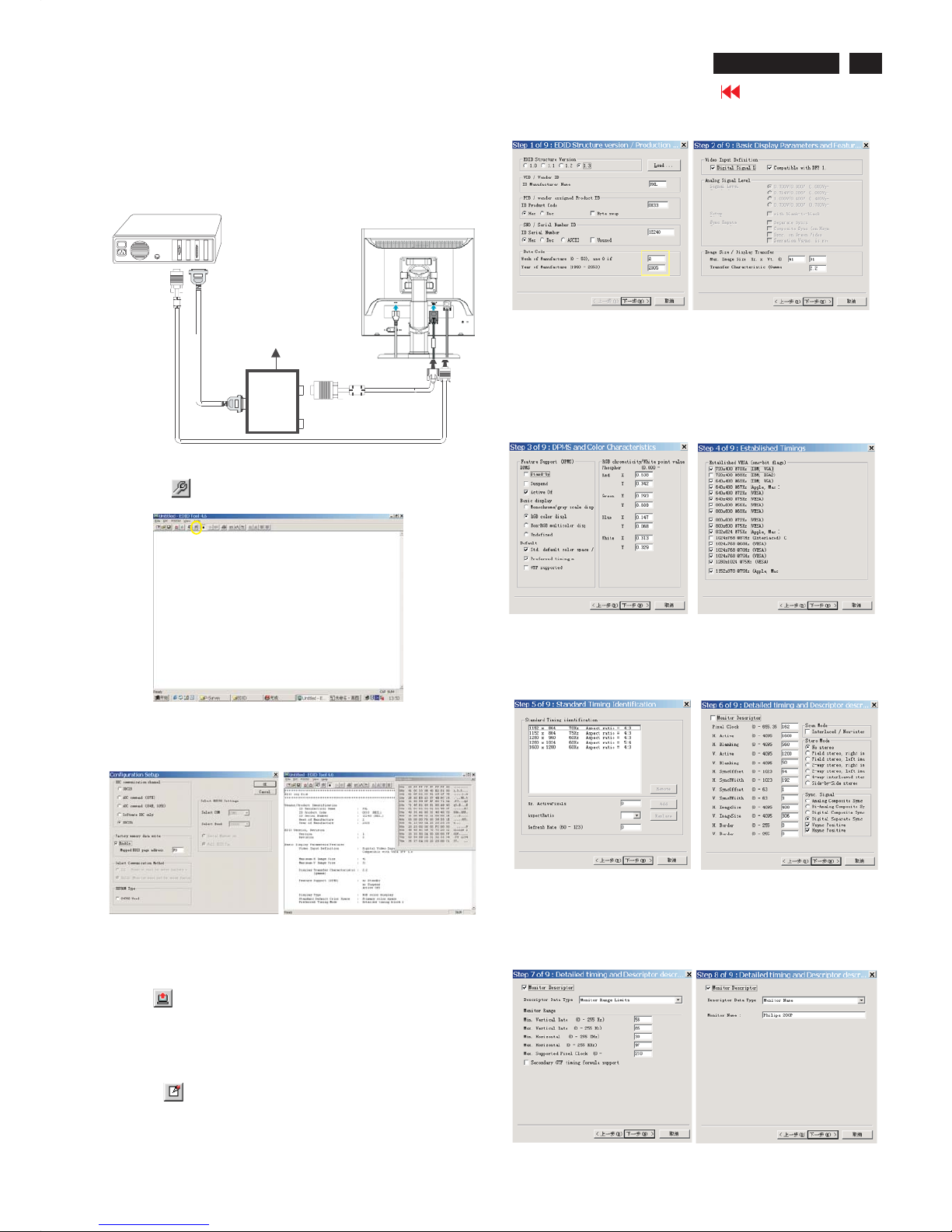
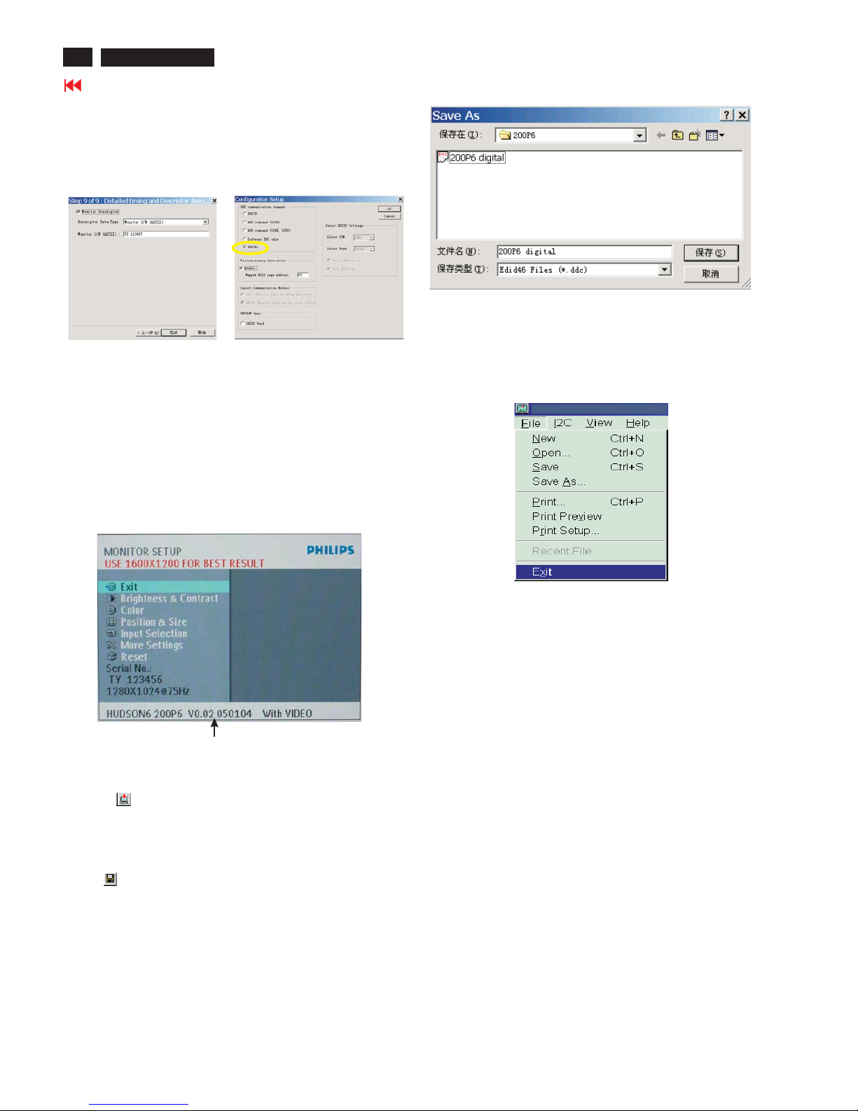
Step 3: Modify DDC data (verify EDID version, week,
year)
Click (new function) icon from the tool bar, bring up
Step 1 of 9 as shown in Fig. 31 .
EDID46 DDC application provides the function selection and
text change (select & fill out) from Step 1 to Step 9.
Step 4: Modify DDC data (Monitor Serial No.)
1. Click Next , bring up Fig. 32.
3. Click OK button to confirm your selection.
4. Click icon (Read EDID function) to read DDC EDID data from
monitor. The EDID codes will display on screen as shown in Fig. 30.
Fig. 32
2. Select the DDC2Bi as the communication channel.
As shown in Fig. 29.
Fig. 29
Fig. 30
Fig. 31
Select and fill out,
If necessary.
Re-programming Digital DDC IC
Step 1: After initialize alignment box, connecting all
cables and box as shown in Fig. 27.
Fig. 28
Step 2: Read DDC data from monitor
1. Click icon as shown in Fig. 11 from the tool bar to bring up
the Channels "Configuration Setup" windows as shown in Fig. 28.
Fig. 27
Click this button
=====>
D-sub to DVI-D cable
1=DVI-D connector
2=D-sub connector
3=Power Plug
2
1
3
D-sub cable
DC Power
8 12V
~
PC
To video card
To printer port (LTP1)
To
Monitor
Printer
Port
Fig. 38
Fig. 35
Fig. 36
7. Click Next , bring up Fig. 38.
4. Click Next , bring up Fig. 35.
5. Click Next , bring up Fig. 36.
6. Click Next , bring up Fig. 37.
In this step, please confirm the Descriptor Data Type is
Monitor Range Limits, and all the items are same as below.
Fig. 37
2. Click Next , bring up Fig. 33.
Fig. 33
Fig. 34
3. Click Next , bring up Fig. 34.
24
Go to cover page
DDC Instructions
200P6 LCD
3. Click (Write EDID) icon from the tool bar to write DDC data.
Then wait for 20-30 seconds ,DDC data will be finished Writing.
Fig. 41
Fig. 39
8. Click Next , bring up Fig. 39.
- Click Finish to exit the Step window.
- Serial number can be filled up at this moment (for example, TY
123457).
NOTE: You must modify the Serial NO. In step 9, otherwise the Serial
NO. In OSD Couldn't be modified correctly.
Step 5: Write DDC data
1. Configuration should be as Fig. 40. And press OK.
Fig. 40
2. Click Save.
Step 7: Exit DDC program
Pull down the File menu and select Exit as shown in Fig. 43.
Step 8: Turn off the monitor, exit the factory mode.
Fig. 43
3) Push Menu to exit OSD menu.""
Fig.42
Sometimes, you may need to save DDC data as a text file for using
in other IC chip. To save DDC data, follow the steps below:
1. Click (Save) icon (or click "file"-> "save as") from the tool bar and
give a file name as shown in Fig. 42.
The file type is EDID46 file (*.ddc) which can be open in WordPad. By
using WordPad, the texts of DDC data & table (128 bytes, hex
code) can be modified. If DDC TEXTS & HEX Table ar completely
correct, it can be saved as *.ddc flie to re-load it into DDC IC for DDC
Data application.
Step 6: Save DDC data
2. Access Factory Mode
1). Turn off monitor.
2).
3).Press "OK" button, wait until the OSD menu with Characters
"HUDSON6 200P6 V0.02 050104 With VIDEO" (below OSD
menu) come on the Screen of the monitor. as shown in Fig41.
[Push "AUTO" & "OK" buttons at the same time and hold them]
+[Press "power" button untill comes out "Windows screen" ]
=> then release all buttons
Factory Mode indicator
 Loading...