

Page 1

Philips Consumer Electronics
Technical Service Data
Service and Quality
Service Publications Dept.
One Philips Drive
P.O. Box 14810
Knoxville, TN 37914
Manual 7561
Model no.: 19PR15C1
First Publish: 8-21-98
Rev. Date: 01-24-2006
Print Date: 1/24/2006
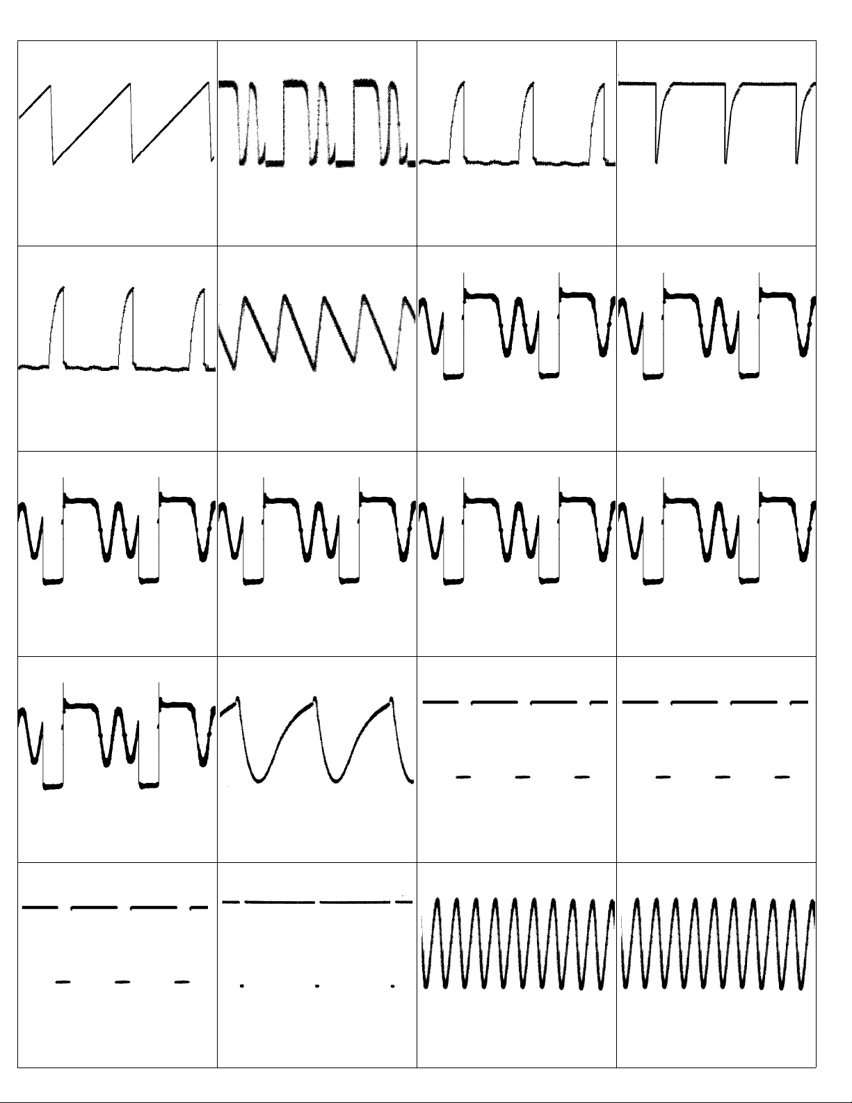
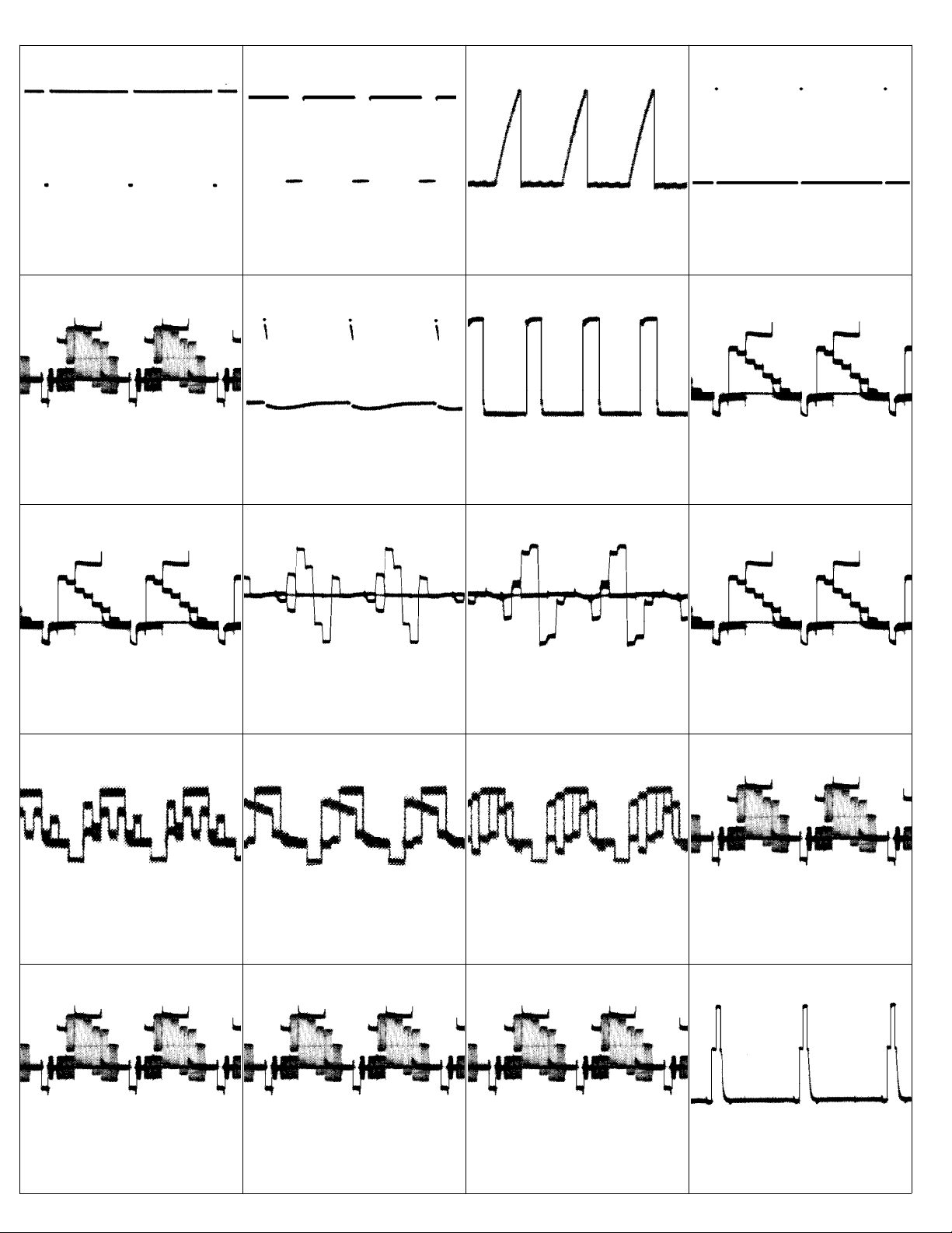
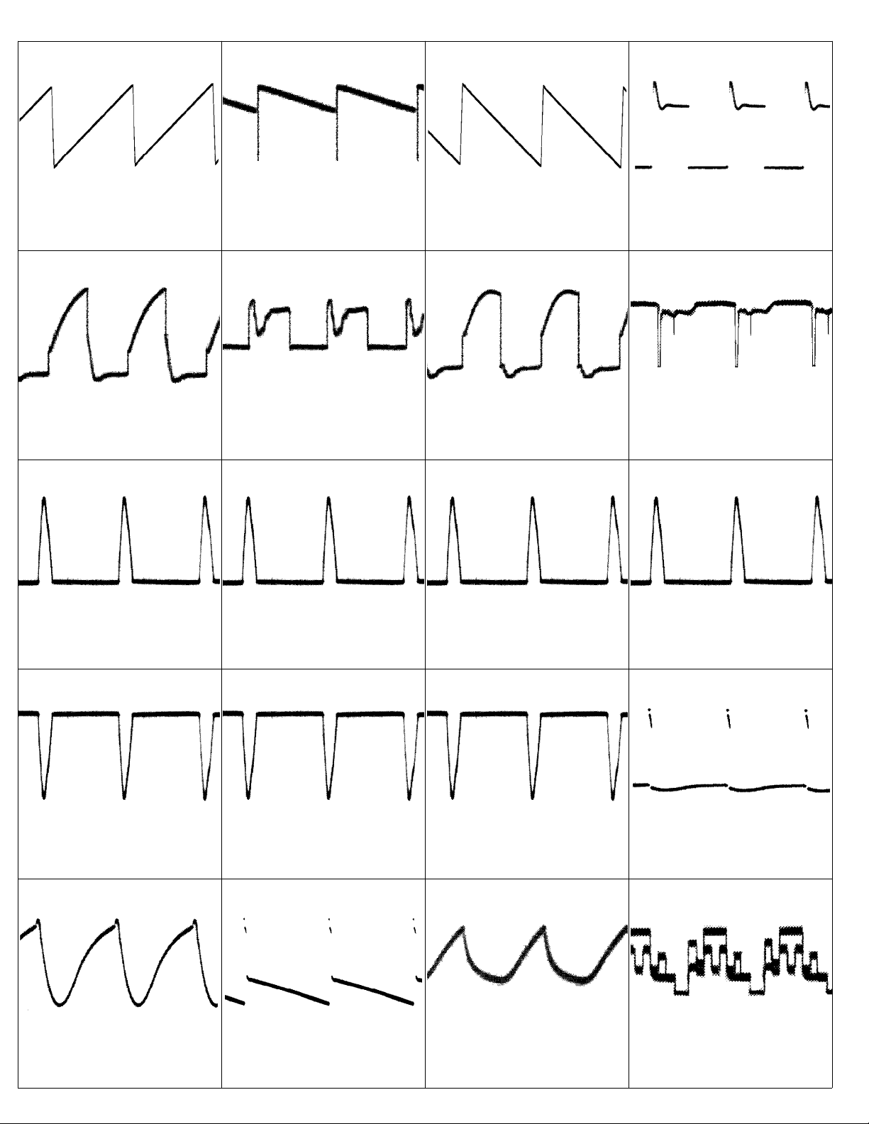
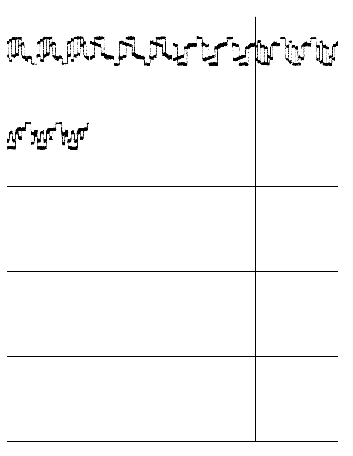
Scope Patterns
REFER TO SAFETY GUIDELINES
SAFETY NOTICE: ANY PERSON ATTEMPTING TO SERVICE THIS CHASSIS MUST FAMILIARIZE
HIMSELF WITH THE CHASSIS AND BE AWARE OF THE NECESSARY SAFETY PRECAUTIONS
TO BE USED WHEN SERVICING ELECTRONIC EQUIPMENT CONTAINING HIGH VOLTAGES.
CAUTION: USE A SEPARATE ISOLATION TRANSFORMER FOR THIS UNIT WHEN SERVICING
© Philips Electronics North America Corporation Visit our World Wide Web Site at http://www.forceonline.com
Page 2
19PR15C1(7561) Page: 1
1
2Vp-p
5uSec
5
11.5Vp-p
5uSec
2
0.8Vp-p
5uSec
6
6Vp-p
5mSec
3
11.2Vp-p
5uSec
7A
38Vp-p
5uSec
4
8.1Vp-p
5uSec
7B
22Vp-p
5uSec
7C
5uSec
8B
40Vp-p
5uSec
7D
200Vp-p
5uSec
9
1Vp-p
5mSec
7E
32Vp-p
5uSec
10
2.7Vp-p
5mSec
8A
280Vp-p
5uSec
11
4.8Vp-p
5mSec
12
4.8Vp-p
5mSec
13
5Vp-p
5mSec
14
5Vp-p
0.1uSec
15
4Vp-p
0.1uSec
Page 3
19PR15C1(7561) Page: 2
16
4.8Vp-p
5mSec
20
1Vp-p
20uSec
17
4.5Vp-p
20uSec
21
1.8Vp-p
5mSec
18
2.3Vp-p
0.2uSec
22
0.9Vp-p
20uSec
19
4.5Vp-p
20uSec
23
1Vp-p
20uSec
24
1Vp-p
20uSec
28
2.8Vp-p
20uSec
25
1.6Vp-p
20uSec
29
2.6Vp-p
20uSec
26
1.4Vp-p
20uSec
30
2.6Vp-p
20uSec
27
1.4Vp-p
20uSec
31
2.5Vp-p
20uSec
32
2.2Vp-p
20uSec
33
1Vp-p
20uSec
34
2.3Vp-p
20uSec
35
5.7Vp-p
20uSec
Page 4
19PR15C1(7561) Page: 3
36
3.2Vp-p
5mSec
40
8.1Vp-p
20uSec
37
1.6Vp-p
5mSec
41
1.1Vp-p
20uSec
38
1.5Vp-p
5mSec
42
5Vp-p
20uSec
39
2.3Vp-p
20uSec
43
11Vp-p
20uSec
44
725Vp-p
20uSec
46A
45Vp-p
20uSec
45A
20uSec
46B
51Vp-p
20uSec
45B
22Vp-p
20uSec
46C
102Vp-p
20uSec
45C
110Vp-p
20uSec
47
28Vp-p
5mSec
48
1Vp-p
5mSec
49
48Vp-p
5mSec
50
1.1Vp-p
5mSec
51
78Vp-p
20uSec
Page 5
19PR15C1(7561) Page: 4
52
1.3Vp-p
20uSec
56
82Vp-p
20uSec
53
2.5Vp-p
20uSec
54
80Vp-p
20uSec
55
1.3Vp-p
20uSec
Page 6
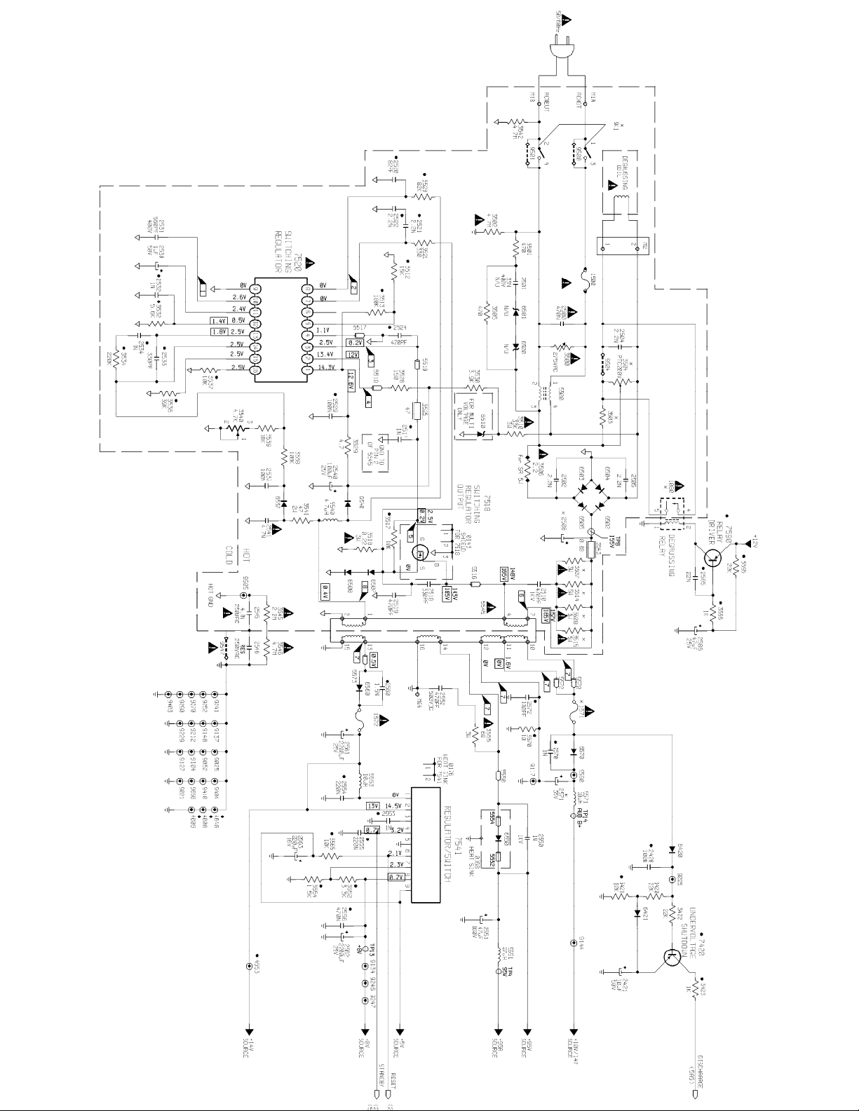
19PR15C1(7561) - A8 MAIN CHASSIS (SECTION 1) Page: 1 of 15
Page 7
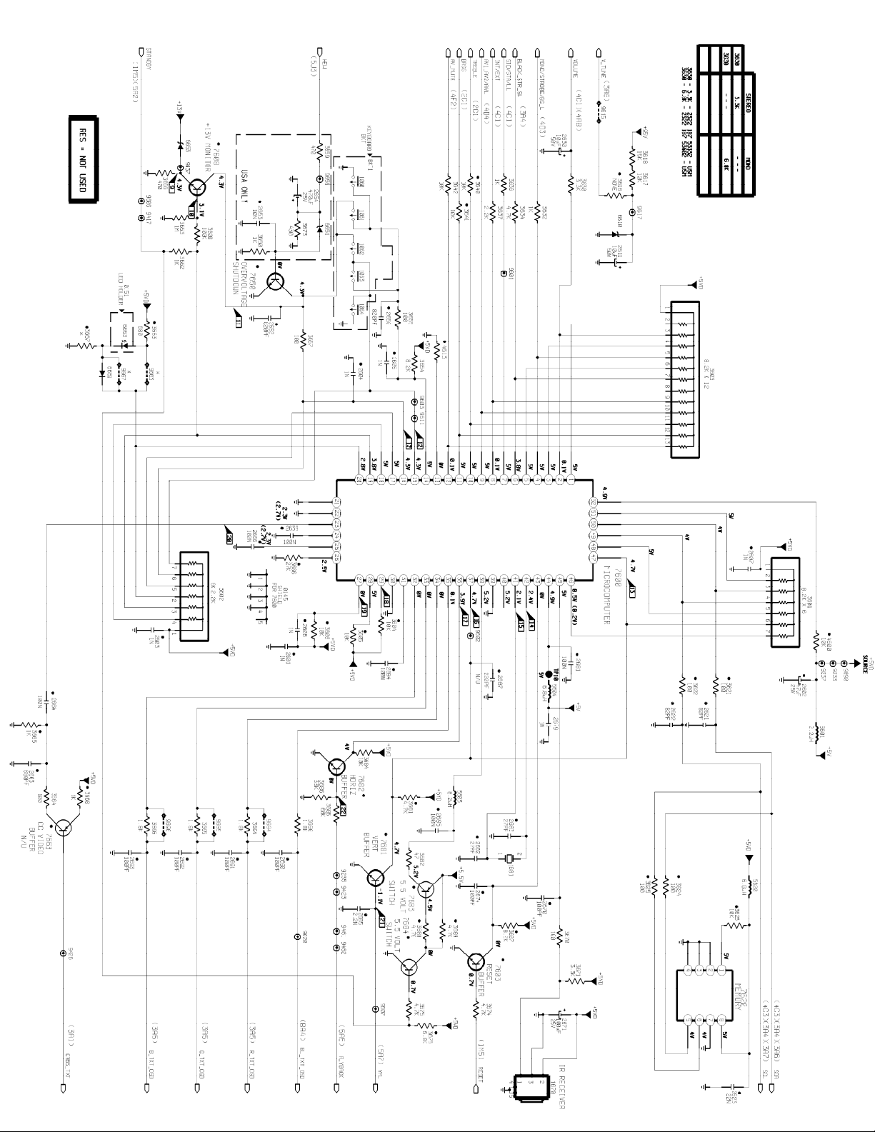
19PR15C1(7561) - A8 MAIN CHASSIS (SECTION 2) Page: 2 of 15
Page 8
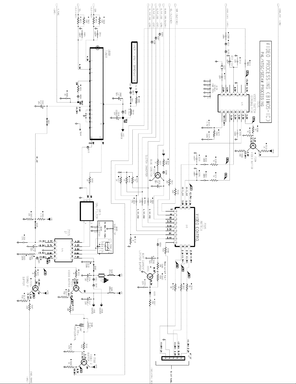
19PR15C1(7561) - A8 MAIN CHASSIS (SECTION 3) Page: 3 of 15
Page 9
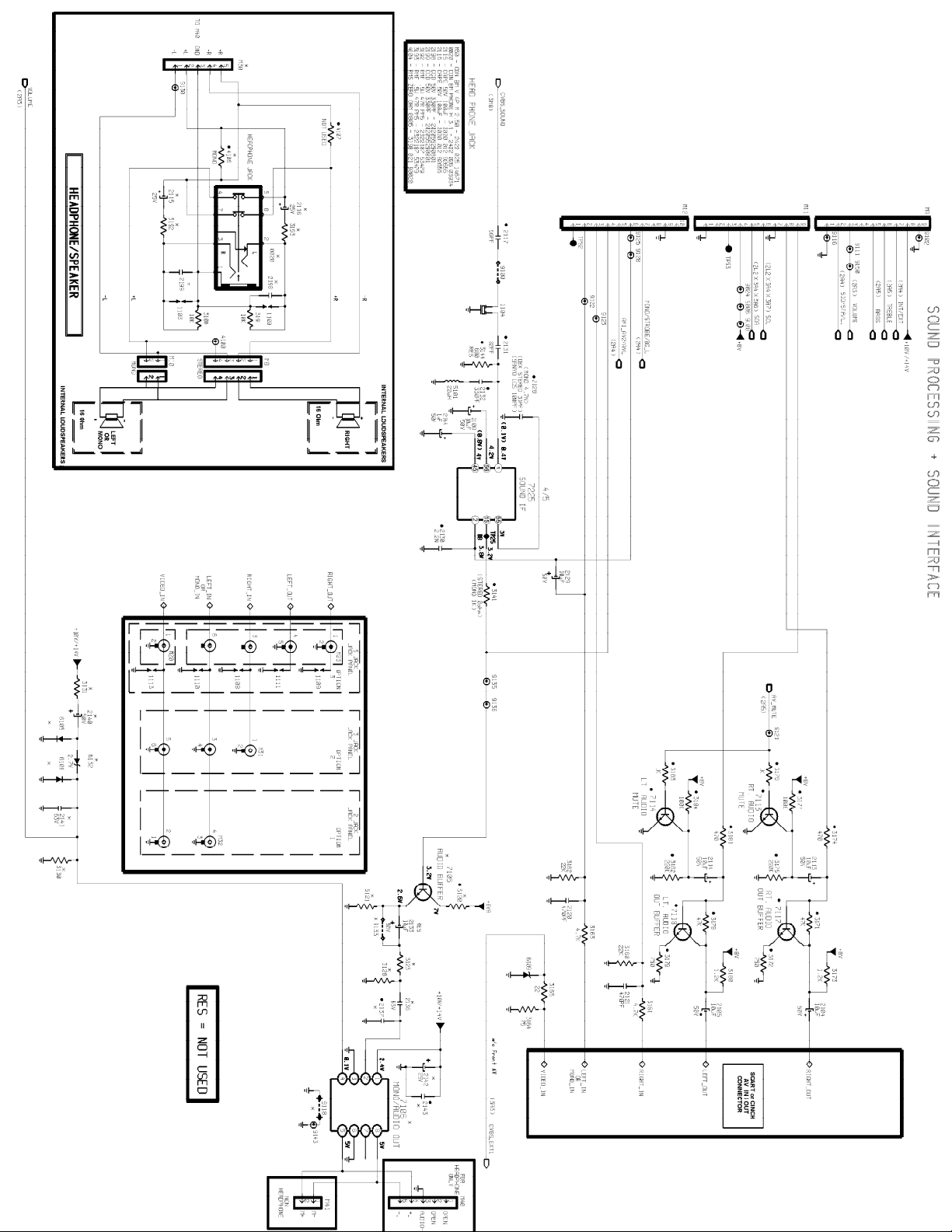
19PR15C1(7561) - A8 MAIN CHASSIS (SECTION 4) Page: 4 of 15
Page 10
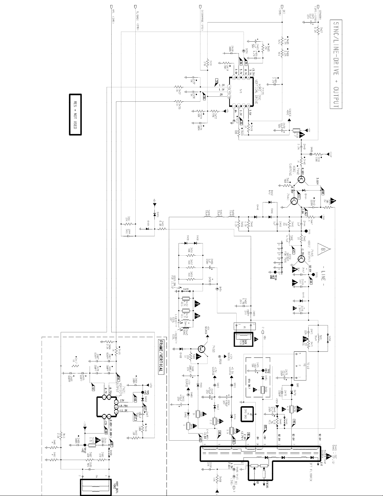
19PR15C1(7561) - A8 MAIN CHASSIS (SECTION 5) Page: 5 of 15
Page 11
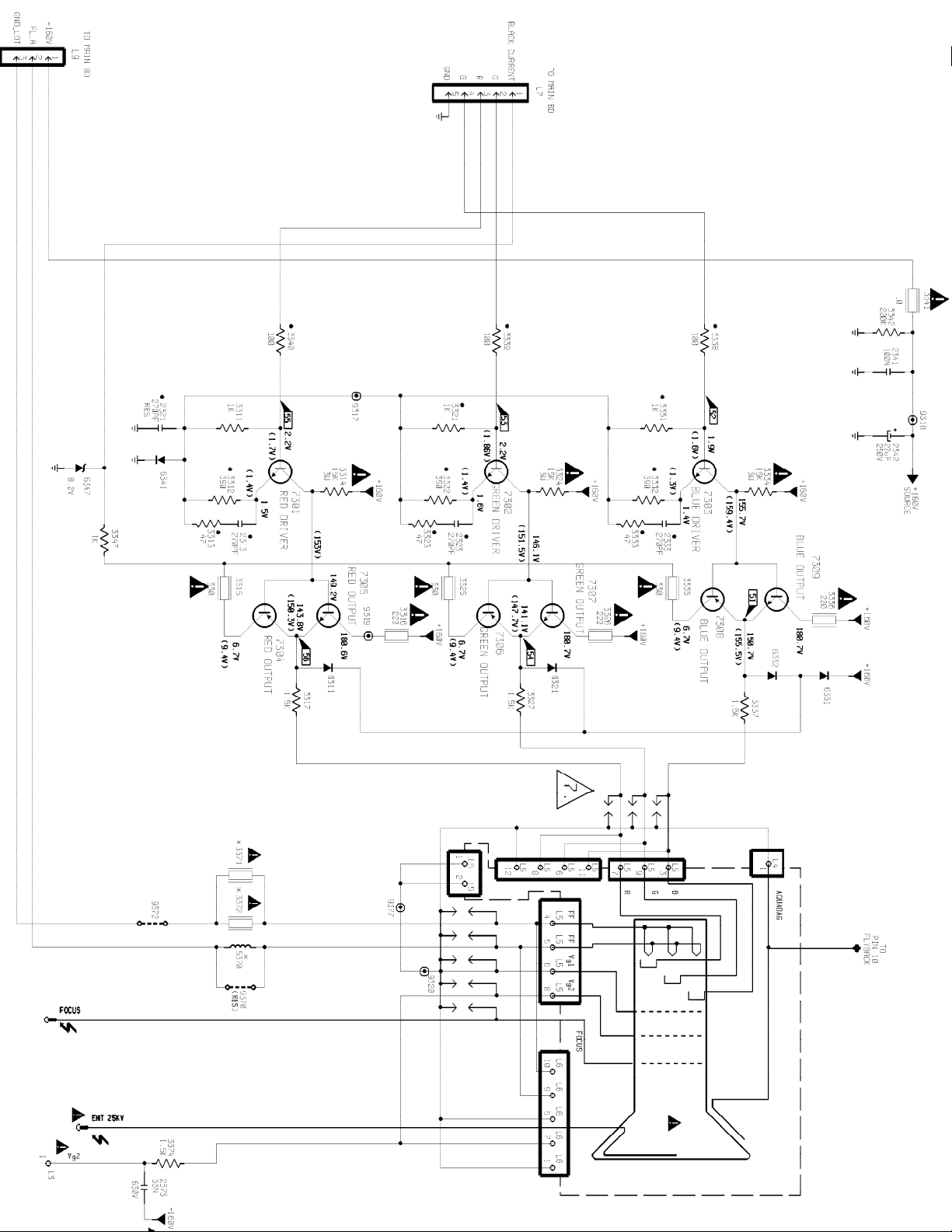
19PR15C1(7561) - APT189 13", 19" & 20" CRT MODULE Page: 6 of 15
Page 12
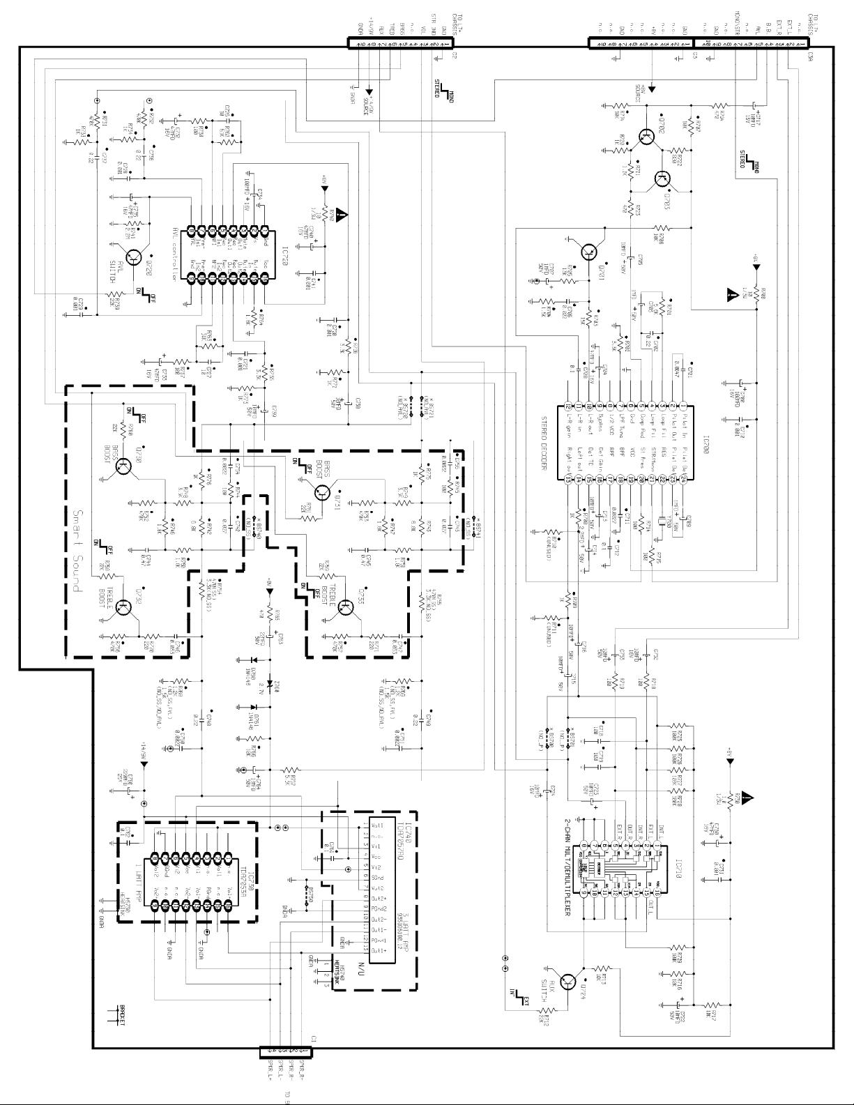
19PR15C1(7561) - ASD039/040 LEAD STEREO (NON DBX) MODULE Page: 7 of 15
Page 13
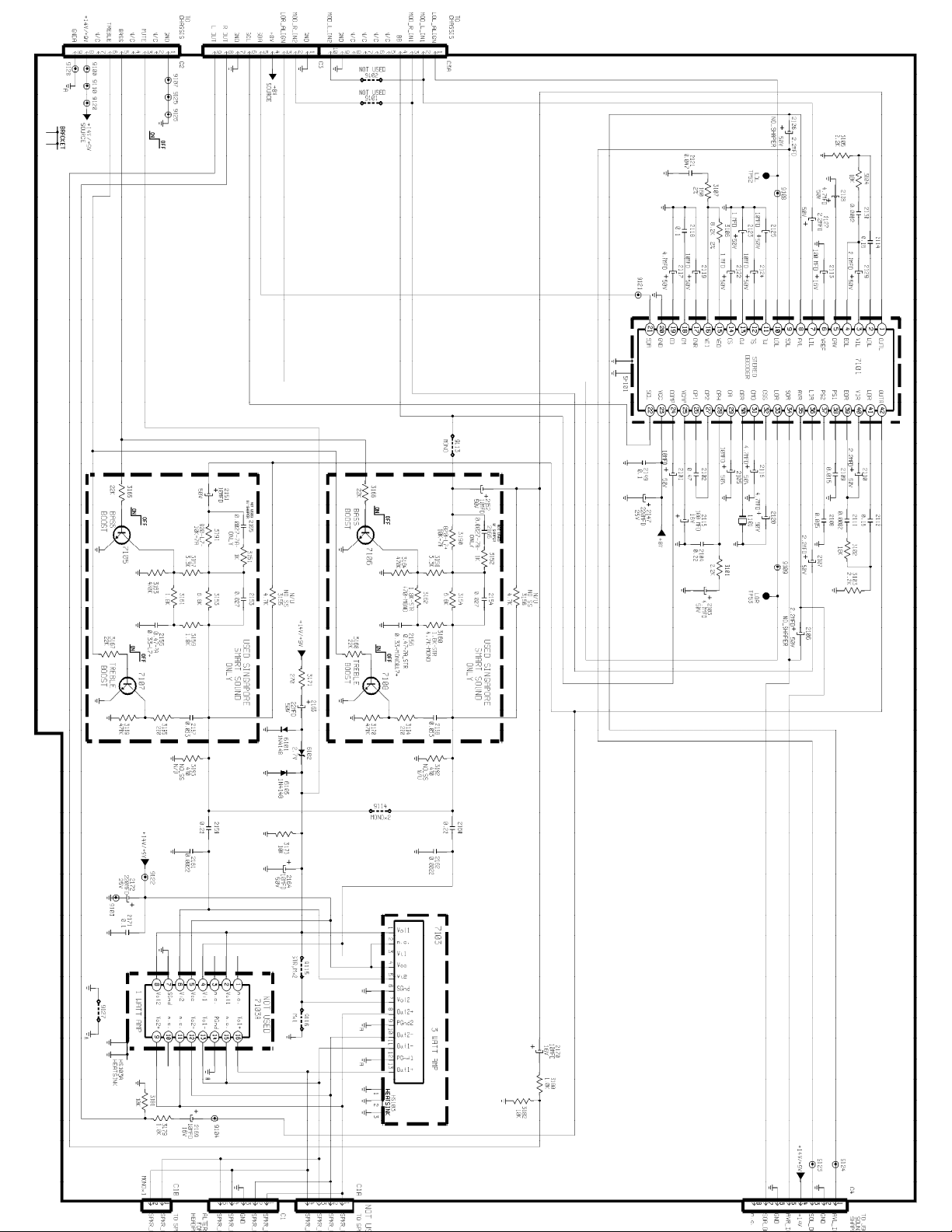
19PR15C1(7561) - ASD042/043/047 DBX STEREO MODULE Page: 8 of 15
Page 14
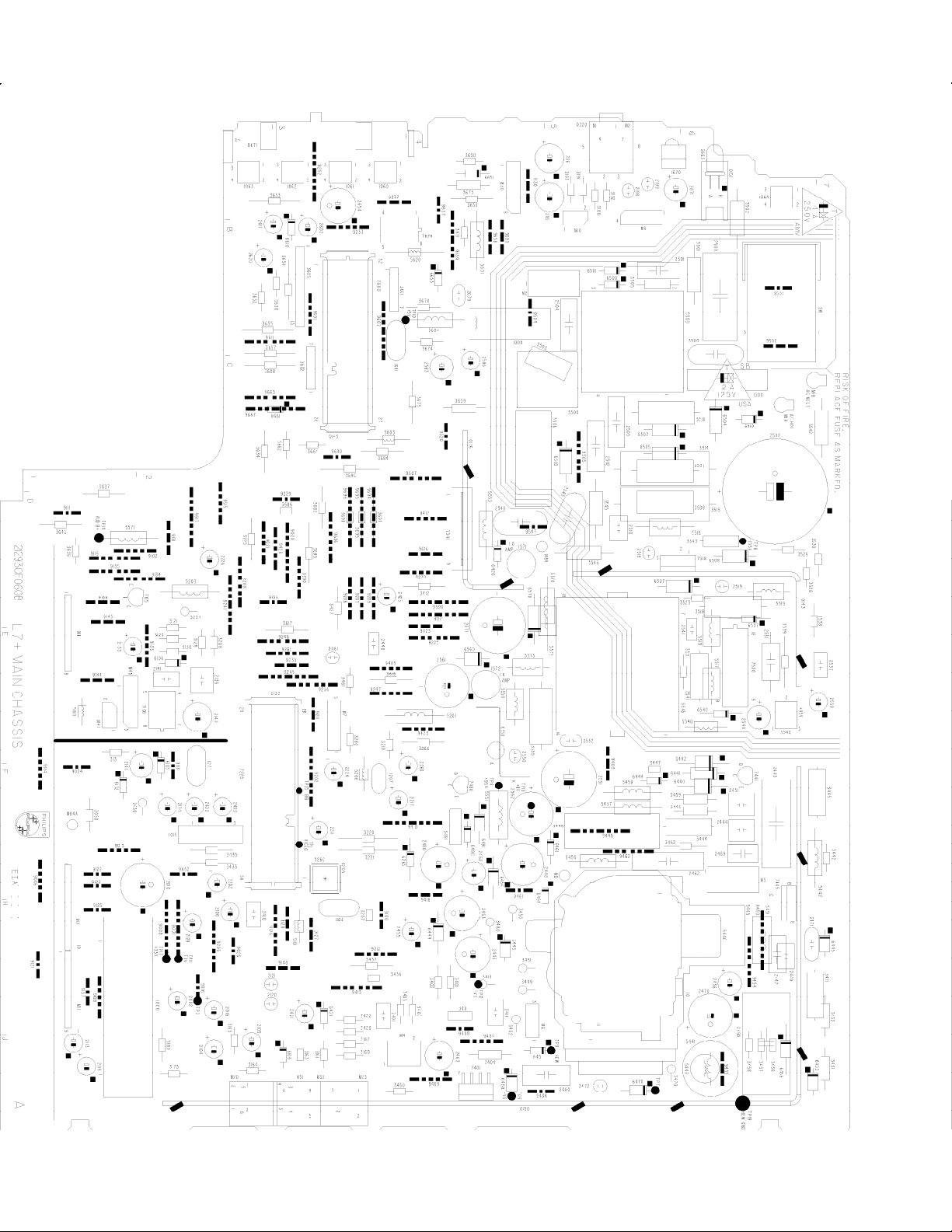
19PR15C1(7561) - A8 MAIN CHASSIS PCB (TOP) Page: 9 of 15
Page 15
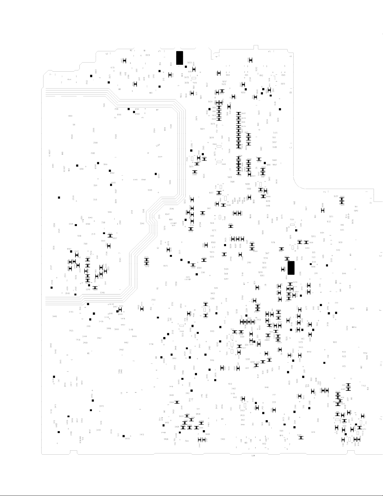
19PR15C1(7561) - A8 MAIN CHASSIS PCB (BOTTOM) Page: 10 of 15
Page 16
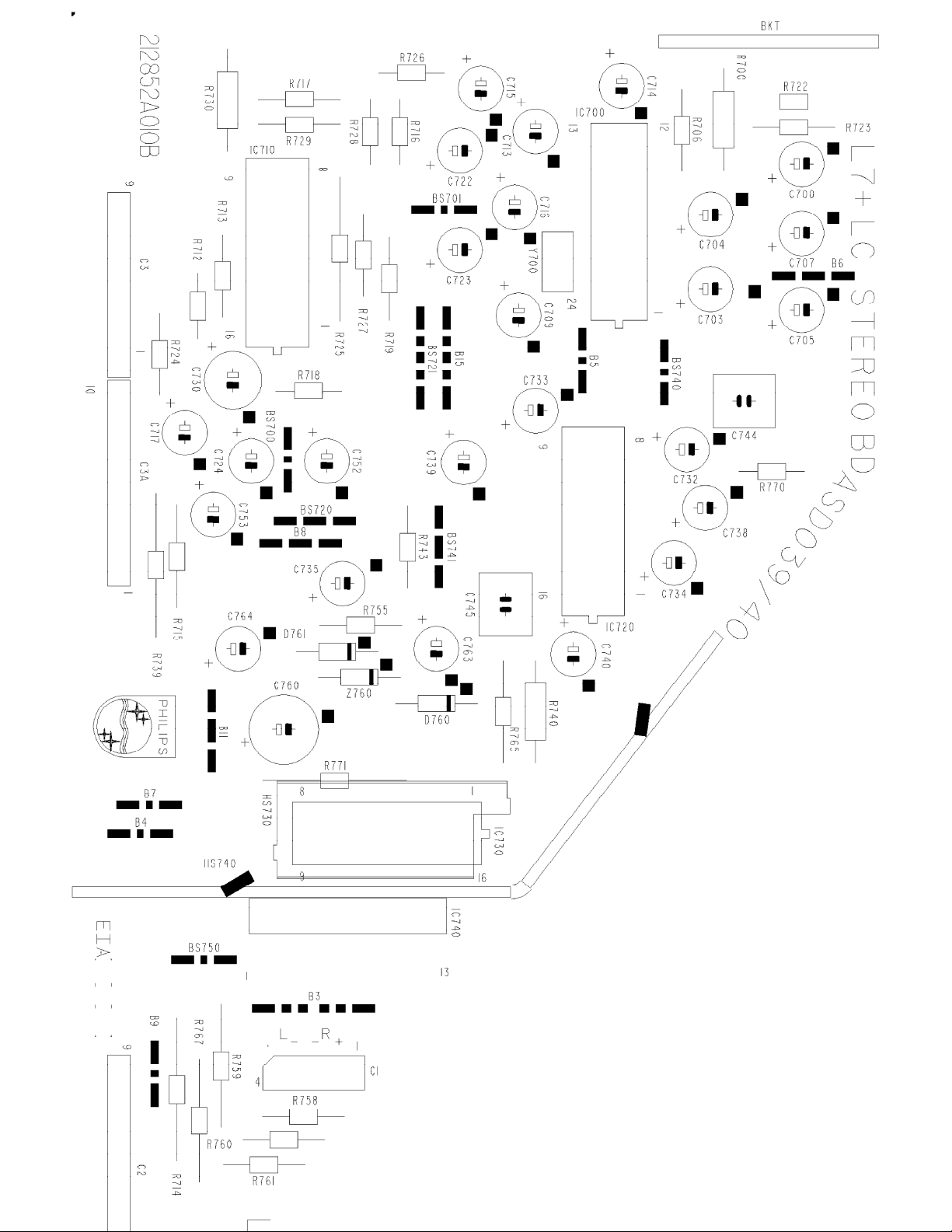
19PR15C1(7561) - ASD039/040 LEAD STEREO (NON DBX) MODULE PCB (TOP) Page: 11 of 15
Page 17
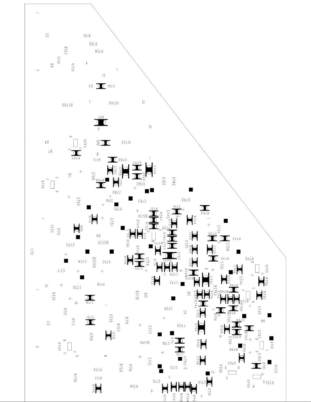
19PR15C1(7561) - ASD039/040 LEAD STEREO (NON DBX) MODULE PCB (BOTTOM) Page: 12 of 15
Page 18
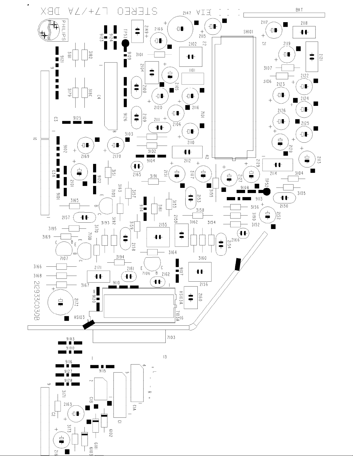
19PR15C1(7561) - ASD042/043 DBX STEREO MODULE PCB Page: 13 of 15
Page 19
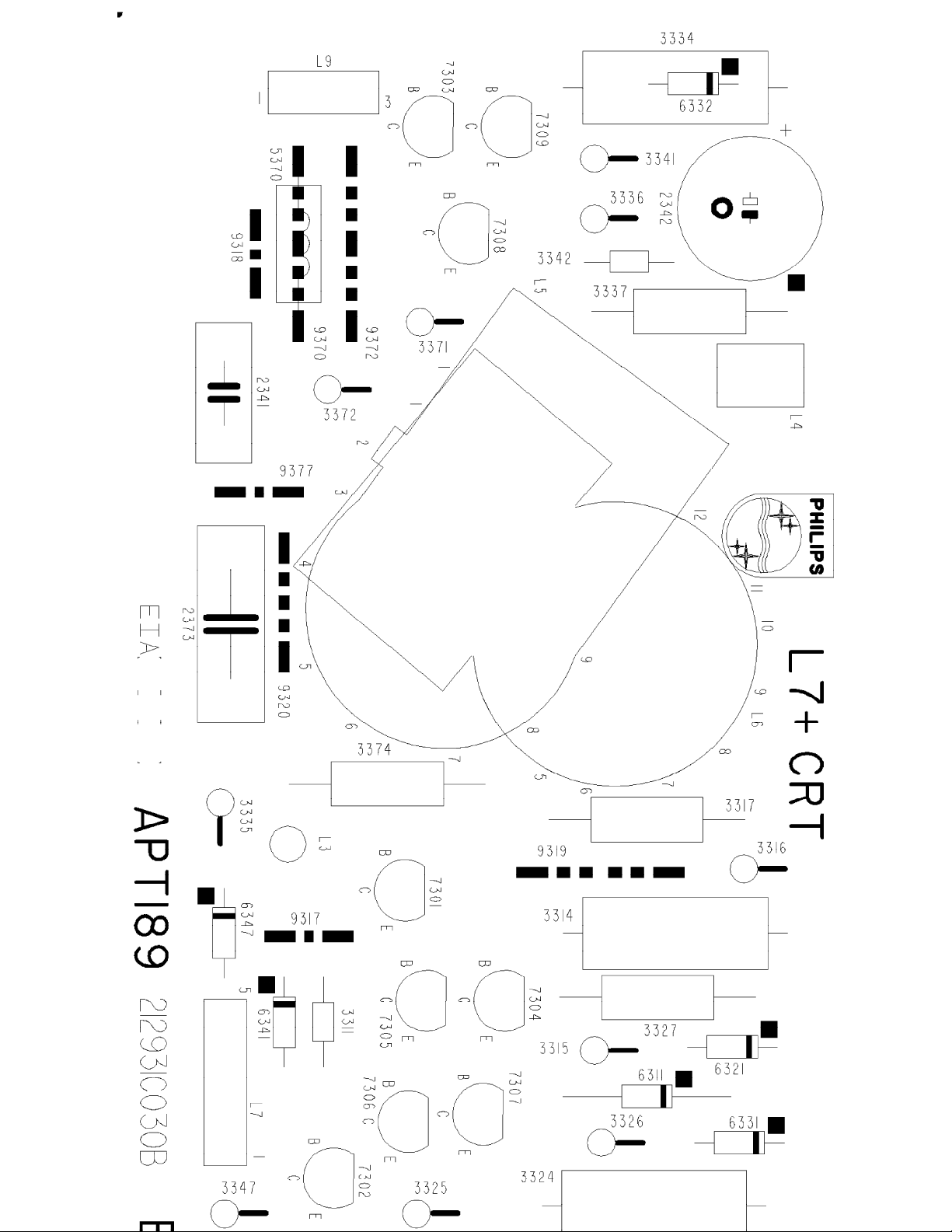
19PR15C1(7561) - APT189 13", 19" & 20" CRT MODULE PCB (TOP) Page: 14 of 15
Page 20

19PR15C1(7561) - APT189 13", 19" & 20" CRT MODULE PCB (BOTTOM) Page: 15 of 15
Page 21

A8 CHASSIS Service Default Mode
The A8 chassis Service Default Mode provides information about features, software version and error
codes. To enter the Service Default Mode, press the following key sequence on the remote control
transmitter.
0-6-2-5-9-6-Menu
Do not allow the display to time out between entries while keying the sequence. While in the Service
Default Mode you may step into customer action by pressing menu. Customer adjustments can be
made. By pressing the status button on the remote the customer menu will disappear and you may
channel scan. Pressing the menu button on the remote twice will return you to the customer menu, then
to the service menu. To exit the Service Default Mode, turn the television off with the remote control
transmitter Power button.
When the unit is operating in Service Default Mode, all normal on-screen displays are suppressed and
replaced by a special service display. A sample service display is shown.
Explanation of Display
The first number (2C2B in the example) is a run timer. This display will increment based on the amount
of time the set has been on. The display will also be incremented each time the set is turned on.
The second number (2.12.8 in the example) shows the software ID (2), the software version (12), and the
cluster number (8) DBX or (83) stereo but not DBX.
The S indicates that the Service Default Mode is active. The S is displayed in green; all other OSD items
will be displayed in red.
The next line is a coded representation of the features of the set (BL in the example). The codes and
their meanings are shown below: Cluster 8 used with mono or with ASD042/43 stereo module and
Cluster 83 used with ASD039/40 stereo module.
Codes for 8 (DBX Stereo or Mono)
Code Meaning
BA Bass Boost
BL Balance in menu
Page 22

BO Boost in menu
CB Channel Blanking Enable
CL Child Lock in menu
CT Color Temperature in menu
DT Auto Detect BCST/CABL in Autoprogram
FT Fine Tuning in menu
MS Message in menu
SA Spatial Sound in menu
SB Sound Board (MA is mono, BT is dBX stereo)
SL SmartSound AVL
SM Sound Mode
SS Full Smart Sound (Singapore SS) Enable
SU Smart Surf Enable in menu
TR Treble Boost
VI Factory preset mode
VL Volume Limiter
XO External 1 (A/V) input enable and in menu
XS AV Mono/Stereo Enable (not for USA products)
The following codes are not to be reset. They should be left set at 0
Tun.FOA, FOB
EXT.FOA, FOB
Codes for 83 (Stereo but not DBX)
Code Meaning
AS Autoscan Enable
AV AVL in menu
BA Bass Boost
BO Boost in menu
BS Black Stretch
CB Channel Blanking Enable
CO Clock in menu
CT Color Temperature in menu
DC Auto Detect BCST/CABL in Autoprogram
MS Message in menu
SB Sound Board (MA is mono, BT is dBX stereo)
SL SmartSound AVL
SM Sound Mode
SP Smart Picture enable
SU Smart Surf Enable in menu
TR Treble Boost
VI Factory preset mode
VL Volume Limiter
XO External 1 (A/V) input enable and in menu
The following codes are not to be reset. They should be left set at 0
Tun.FOA, FOB
EXT.FOA, FOB
Note that if the memory IC (EEPROM) is replaced during service, the microprocessor will write default
values into the EEPROM when the set is initially powered on. No other action is required of the servicer
Page 23

except to set features and adjust all alignment values.
OPTIONS SETTING
The five most recent errors are encoded on the following line of the display (in the example above, no
errors have been recorded, because all five registers display zeroes). The most recent error will be
displayed in the register nearest the word "ERROR". The error codes and their meanings are shown
below.
Code Meaning
0 No Error
1 Micro RAM Error
2 General I2C (SCL/SDA) Buss Error
3 EEPROM Checksum Error
4 DBX Stereo Decoder Error
5 Signal Processor Error
6 EEPROM Error
7 Tuner Error (PLL)
The last line of the OSD is a hexadecimal representation of all active features of the set, e.g., FFFF FFFF
1F5F.
To exit the service mode and erase the error codes, turn the unit off with the power button on the remote
control, then unplug the ac cord. Breaking the ac ensures that the microprocessor will download new
settings from the EEPROM IC when power is reapplied to the set. To save the error codes, unplug the
ac cord without turning off the set. When the power is turned back on, the service mode will still be active.
Page 24

Philips Consumer Electronics
Technical Service Data
Service and Quality
Service Publications Dept.
One Philips Drive
P.O. Box 14810
Knoxville, TN 37914
Pg. SCHEMATIC DIAGRAMS AND PC BOARDS
1. A8 MAIN CHASSIS (SECTION 1)
2. A8 MAIN CHASSIS (SECTION 2)
3. A8 MAIN CHASSIS (SECTION 3)
4. A8 MAIN CHASSIS (SECTION 4)
5. A8 MAIN CHASSIS (SECTION 5)
6. APT189 13", 19" & 20" CRT MODULE
7. ASD039/040 LEAD STEREO (NON DBX) MODULE
8. ASD042/043/047 DBX STEREO MODULE
Manual 7561
Model no.: 19PR15C1
First Publish: 8-21-98
Rev. Date: 01-24-2006
Print Date: 1/24/2006
9. A8 MAIN CHASSIS PCB (TOP)
10. A8 MAIN CHASSIS PCB (BOTTOM)
11. ASD039/040 LEAD STEREO (NON DBX) MODULE PCB (TOP)
12. ASD039/040 LEAD STEREO (NON DBX) MODULE PCB (BOTTOM)
13. ASD042/043 DBX STEREO MODULE PCB
14. APT189 13", 19" & 20" CRT MODULE PCB (TOP)
15. APT189 13", 19" & 20" CRT MODULE PCB (BOTTOM)
REFER TO SAFETY GUIDELINES
SAFETY NOTICE: ANY PERSON ATTEMPTING TO SERVICE THIS CHASSIS MUST FAMILIARIZE
HIMSELF WITH THE CHASSIS AND BE AWARE OF THE NECESSARY SAFETY PRECAUTIONS
TO BE USED WHEN SERVICING ELECTRONIC EQUIPMENT CONTAINING HIGH VOLTAGES.
CAUTION: USE A SEPARATE ISOLATION TRANSFORMER FOR THIS UNIT WHEN SERVICING
© Philips Electronics North America Corporation Visit our World Wide Web Site at http://www.forceonline.com
Page 25

Philips Consumer Electronics
Technical Service Data
Service and Quality
Service Publications Dept.
One Philips Drive
P.O. Box 14810
Knoxville, TN 37914
Manual 7561
Model no.: 19PR15C1
First Publish: 8-21-98
Rev. Date: 01-24-2006
Print Date: 1/24/2006
Safety Notes
REFER TO SAFETY GUIDELINES
SAFETY NOTICE: ANY PERSON ATTEMPTING TO SERVICE THIS CHASSIS MUST FAMILIARIZE
HIMSELF WITH THE CHASSIS AND BE AWARE OF THE NECESSARY SAFETY PRECAUTIONS
TO BE USED WHEN SERVICING ELECTRONIC EQUIPMENT CONTAINING HIGH VOLTAGES.
CAUTION: USE A SEPARATE ISOLATION TRANSFORMER FOR THIS UNIT WHEN SERVICING
© Philips Electronics North America Corporation Visit our World Wide Web Site at http://www.forceonline.com
Page 26

GENERAL SAFETY NOTES
IMPORTANT SAFETY NOTICE
Proper service and repair is important to the safe, reliable operation of all Philips Consumer Electronics
Company** equipment. The service procedures recommended by Philips and described in this service
manual are effective methods of performing service operations. Some of these service operations require
the use of tools specially designed for the purpose. The special tools should be used when and as
recommended.
It is important to note that this manual contains various CAUTIONS and NOTICES which should be
carefully read in order to minimize the risk of personal injury to service personnel. The possibility exists
that improper service methods may damage the equipment. It also is important to understand that these
CAUTIONS and NOTICES ARE NOT EXHAUSTIVE. Philips could not possibly know, evaluate and
advise the service trade of all conceivable ways in which service might be done or of the possible
hazardous consequences of each way. Consequently, Philips has not undertaken any such broad
evaluation. Accordingly, a servicer who uses a service procedure or tool which is not recommended by
Philips must first satisfy himself thoroughly that neither his safety nor the safe operation of the equipment
will be jeopardized by the service method selected.
** Hereafter throughout this manual, Philips Consumer Electronics Company will be referred to as
Philips.
WARNING
Critical components having special safety characteristics are identified with a or
in the parts list and enclosed within a broken line* (where several critical components are grouped in one
area) along with the safety symbol on the schematics or exploded views. Use of substitute
replacement parts which do not have the same specified safety characteristics may create shock, fire, or
other hazards. Under no circumstances should the original design be modified or altered without written
permission from Philips. Philips assumes no liability, express or implied, arising out of any unauthorized
modification of design. Servicer assumes all liability.
• Broken Line ____ _ ____ _ ____ _ ____
"S"
by the Ref. No.
SAFETY CHECKS
After the original service problem has been corrected, a complete safety check should be made. Be sure
to check over the entire set, not just the areas where you have worked. Some previous servicer may
have left an unsafe condition, which could be unknowingly passed on to Your customer. Be sure to check
all of the following:
FIRE AND SHOCK HAZARD
IMPLOSION
X-RADIATION
LEAKAGE CURRENT COLD CHECK
LEAKAGE CURRENT HOT CHECK
PICTURE TUBE REPLACEMENT
Page 27

PARTS REPLACEMENT
FIRE AND SHOCK HAZARD
1. Be sure all components are positioned in such a way as to avoid the possibility of adjacent component
shorts. This is especially important on those chassis which are transported to and from the service shop.
2. Never release a repaired unit unless all protective devices such as insulators, barriers, covers, strain
reliefs, and other hardware have been installed in accordance with the original design.
3. Soldering and wiring must be inspected to locate possible cold solder joints, solder splashes, sharp
solder points, frayed leads, pinched leads, or damaged insulation (including the ac cord). Be certain to
remove loose solder balls and all other loose foreign particles.
4. Check across-the-line components and other components for physical evidence of damage or
deterioration and replace if necessary. Follow original layout, lead length, and dress.
5. No lead or component should touch a receiving tube or a resistor rated at 1 watt or more. Lead
tension around protruding metal surfaces or edges must be avoided.
6. Critical components having special safety characteristics are identified with an 'S' by the Ref. No. in
the parts list and enclosed within a broken line* (where several critical components are grouped in one
area) along with the safety symbol on the schematic diagrams and /or exploded views.
7. When servicing any unit, always use a separate isolation transformer for the chassis. Failure to use a
separate isolation transformer may expose you to possible shock hazard, and may cause damage to
servicing instruments.
8. Many electronic products use a polarized ac line cord (one wide pin on the plug). Defeating this
safety feature may create a potential hazard to the servicer and the user. Extension cords which do not
incorporate the polarizing feature should never be used.
9. After reassembly of the unit, always perform an
all exposed metal parts of the cabinet. Also, check all metal control shafts (with knobs removed),
antenna terminals, handles, screws, etc., to be sure the unit may be safely operated without danger of
electrical shock.
* Broken line ____ _ ____ _ ____ _ ____
ac leakage test
or resistance test from the line cord to
IMPLOSION
1. All picture tubes used in current model receivers are equipped with an integral implosion system.
Care should always be used, and safety glasses worn, whenever handling any picture tube. Avoid
scratching or otherwise damaging the picture tube during installation.
2. Use only replacement tubes specified by the manufacturer.
X-RADIATION
Page 28

1. Be sure procedures and instructions to all your service personnel cover the subject of X-radiation.
jumper from the ac line cord.
Potential sources of X-rays in TV receivers are the picture tube and the high voltage circuits. The basic
precaution which must be exercised is to keep the high voltage at the factory recommended level.
2. To avoid possible exposure to X-radiation and electrical shock, only the manufacturer's specified
anode connectors must be used.
3. It is essential that the service technician has an accurate HV meter available at all times. The
calibration of this meter should be checked periodically against a reference standard.
4. When the HV circuitry is operating properly there is no possibility of an X-radiation problem. High
voltage should always be kept at the manufacturer's rated value - no higher - for optimum performance.
Every time a color set is serviced, the brightness should be run up and down while monitoring the HV
with a meter to be certain that the HV is regulated correctly and does not exceed the specified value. We
suggest that you and your technicians review test procedures so that HV and HV regulation are always
checked as a standard servicing procedure, and the reason for this prudent routine is clearly understood
by everyone. It is important to use an accurate and reliable HV meter. It is recommended that the HV
reading be recorded on each customer's invoice, which will demonstrate a proper concern for the
customer's safety.
5. When troubleshooting and making test measurements in a receiver with a problem of excessive high
voltage, reduce the line voltage by means of a Variac to bring the HV into acceptable limits while
troubleshooting. Do not operate the chassis longer than necessary to locate the cause of the excessive
HV.
6. New picture tubes are specifically designed to withstand higher operating voltages without creating
undesirable X-radiation. It is strongly recommended that any shop test fixture which is to be used with
the new higher voltage chassis be equipped with one of the new type tubes designed for this service.
Addition of a permanently connected HV meter to the shop test fixture is advisable. The CRT types used
in these new sets should never be replaced with any other types, as this may result in excessive
X-radiation.
7. It is essential to use the specified picture tube to avoid a possible X-radiation problem.
8. Most TV receivers contain some type of emergency "Hold Down" circuit to prevent HV from rising to
excessive levels in the presence of a failure mode. These various circuits should be understood by all
technicians servicing them, especially since many hold down circuits are inoperative as long as the
receiver performs normally.
LEAKAGE CURRENT COLD CHECK
1. Unplug the ac line cord and connect a jumper between the two prongs of the plug.
2. Turn on the power switch.
3. Measure the resistance value between the jumpered ac plug and all exposed cabinet parts of the
receiver, such as screw heads, antennas, and control shafts. When the exposed metallic part has a
return path to the chassis, the reading should be between 1 megohm and 5.2 megohms. When the
exposed metal does not have a return path to the chassis, the reading must be infinity. Remove the
Page 29

LEAKAGE CURRENT HOT CHECK
1. Do not use an isolation transformer for this test. Plug the completely reassembled receiver directly
into the ac outlet.
2. Connect a
metallic cabinet part and a
3. Use an ac voltmeter with at least 5000 ohms/volt sensitivity to measure the potential across the
resistor.
4.
The potential at any point should not exceed 0.75 volts.
used to make this test; leakage current must not exceed 0.5milliamp. If a measurement is outside of the
specified limits, there is a possibility of shock hazard. The receiver should be repaired and rechecked
before returning it to the customer.
5
. Repeat the above procedure with the ac plug reversed.
necessary when a polarized plug is used. Do not defeat the polarizing feature of the plug.)
1.5k, 1OW resistor
good earth ground
paralleled by a
such as a water pipe, as shown below.
0.15uF. capacitor
A leakage current tester may be
between each exposed
(Note: An ac adapter is
OR
With the instrument completely reassembled, plug the AC line cord directly into a 120V AC outlet.
not use an isolation transformer during this test.)
metering system that complies with American National Standards Institute (ANSI) C101.1 Leakage
Current for Appliances and Underwriters Laboratories (UL) 1410, (50.7).
Use a leakage current tester or a
With the instrument
AC switch first in the on position and then in the off position, measure from a
known earth ground (metal water pipe, conduit, etc.) to all exposed metal
parts of the instrument (antennas, handle brackets, metal cabinet, screw
heads, metallic overlays, control shafts, etc.), especially any exposed metal
parts that offer an electrical return path to the chassis. Any current
measured must not exceed 0.5 milliamp. Reverse the instrument power cord
plug in the outlet and repeat the test. See graphic below.
(Do
Page 30

The primary source of X-radiation in this television receiver is the picture tube. The picture tube utilized
These characteristics are often not evident from visual inspection nor can the protection afforded by them
PICTURE TUBE REPLACEMENT
in this chassis is specially constructed to limit X-radiation emissions. For continued X-radiation protection,
the replacement tube must be the same type as the original, including suffix letter, or a Philips approved
type.
PARTS REPLACEMENT
Many electrical and mechanical parts in Philips television sets have special safety related characteristics.
necessarily be obtained by using replacement components rated for higher voltage, wattage, etc. The
use of a substitute part which does not have the same safety characteristics as the Philips recommended
replacement part shown in this service manual may create shock, fire, or other hazards
TV SAFETY NOTES
SAFETY CHECKS
IMPLOSION
Page 31

X-RADIATION
PICTURE TUBE REPLACEMENT
PARTS REPLACEMENT
WARNING
Before removing the CRT anode cap, turn the unit OFF and short the HIGH VOLTAGE to the CRT DAG
ground.
SERVICE NOTE:
The CRT DAG is not at chassis ground.
TV-VCR COMBI SAFETY NOTES
IMPORTANT SAFETY PRECAUTIONS
Prior to shipment from the factory, our products are strictly inspected for recognized product safety and
electrical codes of the countries in which they are to be sold. However, in order to maintain such
compliance, it is equally important to implement the following precautions when a set is being serviced.
SAFETY PRECAUTIONS FOR TV CIRCUITS
1. Before returning an instrument to the customer, always make a safety check of the entire instrument,
including, but not limited to, the following items:
a. Be sure that no built-in protective devices are defective or have been defeated during servicing. (1)
Protective shields are provided on this chassis to protect both the technician and the customer.
Correctly replace all missing protective shields, including any removed for servicing convenience. (2)
When reinstalling the chassis and/or other assembly in the cabinet, be sure to put back in place all
protective devices, including but not limited to, nonmetallic control knobs, insulating fishpapers,
adjustment and compartment covers/shields, and isolation resistor/capacitor networks. Do not
operate this instrument or permit it to be operated without all protective devices correctly installed and
functioning. Servicers who defeat safety features or fail to perform safety checks may be liable for any
resulting damage.
b. Be sure that there are no cabinet openings through which an adult or child might be able to insert
their fingers and contact a hazardous voltage. Such openings include, but are not limited to, (1)
spacing between the picture tube and the cabinet mask, (2) excessively wide cabinet ventilation slots,
and (3) an improperly fitted and/or incorrectly secured cabinet back cover.
c. Do a
ANY MEASUREMENTS NOT WITHIN THE LIMITS SPECIFIED HEREIN INDICATE A POTENTIAL SHOCK
HAZARD THAT MUST BE ELIMINATED BEFORE RETURNING THE INSTRUMENT TO THE CUSTOMER OR
BEFORE CONNECTING THE ANTENNA OR ACCESSORIES.
LEAKAGE CURRENT CHECK
Page 32

d. X-Radiation and High Voltage Limits - Because the picture tube is the primary potential source
of X-radiation in solid-state TV receivers, it is specially constructed to prohibit X-radiation emissions.
For continued X-radiation protection, the replacement picture tube must be the same type as the
original. Also, because the picture tube shields and mounting hardware perform an X-radiation
protection function, they must be correctly in place. High voltage must be measured each time
servicing is performed that involves B+, horizontal deflection or high voltage. Correct operation of the
X-radiation protection circuits also must be reconfirmed each time they are serviced. (X-radiation
protection circuits also may be called "horizontal disable" or "hold down.") Read and apply the high
voltage limits and, if the chassis is so equipped, the X-radiation protection circuit specifications given
on instrument labels and in the Product Safety & X-Radiation Warning note on the service data
chassis schematic. High voltage is maintained within specified limits by close tolerance safety-related
components/adjustments in the high-voltage circuit. If high voltage exceeds specified limits, check
each component specified on the chassis schematic and take corrective action.
2. Read and comply with all caution and safety-related notes on or inside the receiver cabinet, on the
receiver chassis, or on the picture tube.
3. Design Alteration Warning - Do not alter or add to the mechanical or electrical design of this TV
receiver. Design alterations and additions, including, but not limited to circuit modifications and the
addition of items such as auxiliary audio and/or video output connections, might alter the safety
characteristics of this receiver and create a hazard to the user. Any design alterations or additions will
void the manufacturer's warranty and may make you, the servicer, responsible for personal injury or
property damage resulting therefrom.
4. Picture Tube Implosion Protection Warning - The picture tube in this receiver employs integral
implosion protection. For continued implosion protection, replace the picture tube only with one of the
same type number. Do not remove, install, or otherwise handle the picture tube in any manner without
first putting on shatterproof goggles equipped with side shields. People not so equipped must be kept
safely away while picture tubes are handled. Keep the picture tube away from your body. Do not handle
the picture tube by its neck. Some "in-line" picture tubes are equipped with a permanently attached
deflection yoke; because of potential hazard, do not try to remove such "permanently attached" yokes
from the picture tube.
5. Hot Chassis Warning
a. Some TV receiver chassis are electrically connected directly to one conductor of the ac power cord
and may be serviced safely without an isolation transformer only if the ac power plug is inserted so
that the chassis is connected to the ground side of the ac power source. To confirm that the ac
power plug is inserted correctly, with an ac voltmeter, measure between the chassis and a known
earth ground. If a voltage reading in excess of 1.OV is obtained, remove and reinsert the ac power
plug in the opposite polarity and again measure the voltage potential between the chassis and a
known earth ground.
b. Some TV receiver chassis normally have 85Vac (RMS) between chassis and earth ground
regardless of the ac plug polarity. This chassis can be safety-serviced only with an isolation
transformer inserted in the power line between the receiver and the ac power source, for both
personnel and test equipment protection. Some TV receiver chassis have a secondary ground system
in addition to the main chassis ground. This secondary ground system is not isolated from the ac
power line. The two ground systems are electrically separated by insulation material that must not
be defeated or altered.
6. Observe original lead dress. Take extra care to assure correct lead dress in the following areas: a.
near sharp edges, b. near thermally hot parts - be sure that leads and components do not touch
Page 33

thermally hot parts, c. the ac supply, d. high voltage, and e. antenna wiring. Always inspect in all areas
for pinched, out of place, or frayed wiring. Check ac power cord for damage.
7. Components, parts, and/or wiring that appear to have overheated or are otherwise damaged should be
replaced with components, parts, or wiring that meet original specifications. Additionally, determine the
cause of overheating and/or damage and, if necessary, take corrective action to remove any potential
safety hazard.
PRECAUTIONS DURING SERVICE
A. Parts identified by the symbol are critical for safety. Replace only with part number specified.
B. In addition to safety, other parts and assemblies are specified for conformance with regulations
applying to spurious radiation. These must also be replaced only with specified replacements.
Examples:
C. Use specified internal wiring. Note especially:
1) Wires covered with PVC tubing
2) Double insulated wires
3) High voltage leads
D. Use specified insulating materials for hazardous
live parts. Note especially:
1) Insulation Tape
2) PVC tubing
3) Spacers
4) Insulators for transistors
RF converters, RF cables, noise blocking capacitors, and noise blocking filters, etc.
E. When replacing ac primary side components (transformers, power cord, etc.), wrap ends of wires
securely about the terminals before soldering.
F. Observe that the wires do not contact heat producing parts (heatsinks, oxide metal film resistors,
fusible resistors, etc.)
G. Check that replaced wires do not contact sharp edged or pointed parts.
H. When a power cord has been replaced, check that 10-15 kg of force in any direction will not
loosen it.
I. Also check areas surrounding repaired locations.
J. Use care that foreign objects (screws, solder droplets, etc.) do not remain inside the set.
K. Crimp type wire connector
When replacing the power transformer in sets where the connections between the power cord and power
transformer primary lead wires are performed using crimp type connectors, in order to prevent shock
hazards, perform carefully and precisely the following steps.
Replacement procedure
1) Remove the old connector by cutting the wires at a point close to the connector. Important: Do
not re-use a connector (discard it).
Page 34

2) Strip about 15 mm of the insulation from the ends of the wires. If the wires are stranded, twist
the strands to avoid frayed conductors.
3) Align the lengths of the wires to be connected. Insert the wires fully into the connector.
4) Use the crimping tool to crimp the metal sleeve at the center position. Be sure to crimp fully to
the complete closure of the tool.
L. When connecting or disconnecting the VCR connectors, first, disconnect the ac plug from the ac supply
socket.
SAFETY CHECK AFTER SERVICING
Examine the area surrounding the repaired location for damage or deterioration. Observe that screws,
parts and wires have been returned to original positions. Afterwards, perform the following tests and
confirm the specified values in order to verify compliance with safety standards.
1. Clearance Distance
When replacing primary circuit components, confirm specified clearance distance (d) and (d') between
soldered terminals, and between terminals and surrounding metallic parts. (See graphic bllow)
Table 1 : Ratings for selected area
AC Line Voltage Region Clearance Distance
(d) (d')
USA or > 3.2 mm
110 to 130 V CANADA (0.126 inches)
Note: This table is unofficial and for reference only. Be sure to confirm the precise values.
2.
LEAKAGE CURRENT CHECKS
Page 35

VCR SAFETY NOTES
This device employs many circuits, components, and mechanical parts designed for protection against
FIRE & SHOCK HAZARD (VCR)
1. Be sure that all components are positioned in such a way to avoid possibility of shorts to adjacent
components. This is especially important on those chassis which are transported to and from the repair
shop.
2. Always replace all protective devices such as insulators and barriers after working on a set.
3. Check for damaged insulation on wires including the ac cord.
4. Check across-the-line components for damage and replace if necessary.
5. After re-assembly of the unit, always perform an ac leakage test on the exposed metallic parts of the
cabinet such as the knobs, antenna terminals, etc. to be sure the set is safe to operate without danger of
electrical shock. Do not use a line isolation transformer during this test. Use an ac voltmeter
having 5000 ohms per volt or more sensitivity in the following manner: Connect a 1500 ohm 10 wan
resistor, paralleled by 0.15 MFD ac type capacitor, between a known good earth ground (water pipe,
conduit, etc.) and the exposed metallic parts, one at a time. Measure the ac voltage across the
combination 1500 ohm resistor and 0.15 MFD capacitor. Reverse the ac plug on the set and repeat ac
voltage measurements again for each exposed metallic part. Voltage measured must not exceed O.6 volts
R.M.S. This corresponds to 0.4 milliamp ac. Any value exceeding this limit constitutes a potential shock
hazard and must be corrected immediately.
GENERAL
Power Supply-This receiver is designed for operation on 120 Volts, 6OHz alternating current (ac) only.
Never connect to a supply having a different frequency or voltage.
IMPORTANT NOTICE
fire, shock and RF interference. For continued safety any servicing should be performed by qualified
personnel and exact replacement parts should be used. Under no circumstances should the original
design be altered.
PRODUCT SAFETY GUIDELINES FOR ALL PRODUCTS
CAUTION
familiar with all of the following safety checks. Risk of potential hazards and injury to the user increases if
safety checks are not adhered to.
USE A SEPARATE ISOLATION TRANSFORMER FOR THIS UNIT WHEN SERVICING.
: Do not modify any circuit. Service work should be performed only after you are thoroughly
Page 36

PREVENTION OF ELECTROSTATIC DISCHARGE (ESD)
This reminder is provided to call the CATV system installer's attention to article 820-22 of the NEC that
Some semiconductor solid state devices can be damaged easily by static electricity. Such components
commonly are called Electrostatically Sensitive (ES) Devices, Examples of typical ES devices are
integrated circuits and some field-effect transistors and semiconductor "chip" components. The following
techniques should be used to help reduce the incidence of component damage caused by electrostatic
discharge (ESD).
1. Immediately before handling any semiconductor component or semiconductor-equipped assembly,
drain off any ESD on your body by touching a known earth ground. Alternatively, obtain and wear a
commercially available discharging ESD wrist strap, which should be removed for potential shock reasons
prior to applying power to the unit under test.
2. After removing an electrical assembly equipped with ES devices, place the assembly on a conductive
surface such as aluminum foil, to prevent electrostatic charge buildup or exposure of the assembly.
3. Use only a grounded-tip soldering iron to solder or unsolder ES devices.
4. Use only an anti-static solder removal device. Some solder removal devices not classified as "antistatic
(ESD protected)" can generate an electrical charge sufficient to damage ES devices.
5. Do not use freon·propelled chemicals. These can generate electrical charges sufficient to damage ES
devices.
6. Do not remove a replacement ES device from its protective package until immediately before you are
ready to install it (Most replacement ES devices are packaged with leads electrically shorted together by
conductive foam, aluminum foil or comparable conductive material).
7. Immediately before removing the protective material from the leads of a replacement ES device, touch
the protective material to the chassis or circuit assembly into which the device will be installed.
CAUTION : Be sure no power is applied to the chassis or circuit and observe all other safety precautions.
8. Minimize bodily motions when handling unpackaged replacement ES devices. (Otherwise harmless
motion such as the brushing together of your clothes fabric or the lifting of your feet from a carpeted
floor can generate static electricity (ESD) sufficient to damage an ES device.)
NOTE to CATV system Installer:
provides guidelines for proper grounding and, in particular, specifies that the cable ground shall be
connected to the grounding system of the building, as close to the point of cable entry as practical.
Page 37

Philips Consumer Electronics
Technical Service Data
Service and Quality
Service Publications Dept.
One Philips Drive
P.O. Box 14810
Knoxville, TN 37914
Manual 7561
Model no.: 19PR15C1
First Publish: 8-21-98
Rev. Date: 01-24-2006
Print Date: 1/24/2006
Mechanical Diagrams
REFER TO SAFETY GUIDELINES
SAFETY NOTICE: ANY PERSON ATTEMPTING TO SERVICE THIS CHASSIS MUST FAMILIARIZE
HIMSELF WITH THE CHASSIS AND BE AWARE OF THE NECESSARY SAFETY PRECAUTIONS
TO BE USED WHEN SERVICING ELECTRONIC EQUIPMENT CONTAINING HIGH VOLTAGES.
CAUTION: USE A SEPARATE ISOLATION TRANSFORMER FOR THIS UNIT WHEN SERVICING
© Philips Electronics North America Corporation Visit our World Wide Web Site at http://www.forceonline.com
Page 38

Typical Table Model Exploded View Page: 1 of 1
Page 39

Philips Consumer Electronics
Technical Service Data
Service and Quality
Service Publications Dept.
One Philips Drive
P.O. Box 14810
Knoxville, TN 37914
Manual 7561
Model no.: 19PR15C1
First Publish: 8-21-98
Rev. Date: 01-24-2006
Print Date: 1/24/2006
Troubleshooting
REFER TO SAFETY GUIDELINES
SAFETY NOTICE: ANY PERSON ATTEMPTING TO SERVICE THIS CHASSIS MUST FAMILIARIZE
HIMSELF WITH THE CHASSIS AND BE AWARE OF THE NECESSARY SAFETY PRECAUTIONS
TO BE USED WHEN SERVICING ELECTRONIC EQUIPMENT CONTAINING HIGH VOLTAGES.
CAUTION: USE A SEPARATE ISOLATION TRANSFORMER FOR THIS UNIT WHEN SERVICING
© Philips Electronics North America Corporation Visit our World Wide Web Site at http://www.forceonline.com
Page 40

Page 41

Page 42

Page 43

Philips Consumer Electronics
Technical Service Data
Service and Quality
Service Publications Dept.
One Philips Drive
P.O. Box 14810
Knoxville, TN 37914
Manual 7561
Model no.: 19PR15C1
First Publish: 8-21-98
Rev. Date: 01-24-2006
Print Date: 1/24/2006
Training Information
REFER TO SAFETY GUIDELINES
SAFETY NOTICE: ANY PERSON ATTEMPTING TO SERVICE THIS CHASSIS MUST FAMILIARIZE
HIMSELF WITH THE CHASSIS AND BE AWARE OF THE NECESSARY SAFETY PRECAUTIONS
TO BE USED WHEN SERVICING ELECTRONIC EQUIPMENT CONTAINING HIGH VOLTAGES.
CAUTION: USE A SEPARATE ISOLATION TRANSFORMER FOR THIS UNIT WHEN SERVICING
© Philips Electronics North America Corporation Visit our World Wide Web Site at http://www.forceonline.com
Page 44

Page 45

Page 46

Page 47

Page 48

Page 49

Philips Consumer Electronics
Technical Service Data
Service and Quality
Service Publications Dept.
One Philips Drive
P.O. Box 14810
Knoxville, TN 37914
Manual 7561
Model no.: 19PR15C1
First Publish: 8-21-98
Rev. Date: 01-24-2006
Print Date: 1/24/2006
Parts List
REFER TO SAFETY GUIDELINES
SAFETY NOTICE: ANY PERSON ATTEMPTING TO SERVICE THIS CHASSIS MUST FAMILIARIZE
HIMSELF WITH THE CHASSIS AND BE AWARE OF THE NECESSARY SAFETY PRECAUTIONS
TO BE USED WHEN SERVICING ELECTRONIC EQUIPMENT CONTAINING HIGH VOLTAGES.
CAUTION: USE A SEPARATE ISOLATION TRANSFORMER FOR THIS UNIT WHEN SERVICING
© Philips Electronics North America Corporation Visit our World Wide Web Site at http://www.forceonline.com
Page 50

19PR15C1 - Manual no. 7561 Page: 1
A8 MAIN CHASSIS
2002 1uF,50V,Electrolytic . . . . . . . . . 4835 121 47406
2005 100pF,5%,50V,Ceramic(Not Used In 20" La
tam) . . . . . . . . . . . . . . . . . 4835 122 87012
2008 1000pF,50V,Ceramic . . . . . . . . . . 4835 122 87023
2010 2200uF,16V,Electrolytic. . . . . . . . 4835 124 47701
2011 100pF,5%,50V,Ceramic(Not Used In 20" La
tam) . . . . . . . . . . . . . . . . . 4835 122 87012
2016 0.047uF,25V,Electrolytic . . . . . . . 4835 124 47708
2104 10uF,50V,Electrolytic (19" w/Chld Lck) 4835 124 47499
2105 10uF,50V,Electrolytic (19" w/Chld Lck) 4835 124 47499
2108 10uF,50V,Electrolytic. . . . . . . . . 4835 124 47499
2110 1uF,50V,Electrolytic (Stereo models) . 4835 121 47406
2113 10uF,50V,Electrolytic (19" w/Chld Lck) 4835 124 47499
2114 10uF,50V,Electrolytic (19" w/Chld Lck) 4835 124 47499
2115 100uF,50V,Electrolytic (w/Headphones). 4835 124 47563
2116 100uF,50V,Electrolytic (w/Headphones). 4835 124 47563
2117 56pF,50V,Ceramic . . . . . . . . . . . 4835 122 87373
2120 50V470pF,Ceramic(13",19"w/Chld Lck,w/AS
D039,Latam). . . . . . . . . . . . . . 4835 122 47614
2121 470pF,50V,Ceramic (19" w/Chld Lck,ASD03
9 ,Latam). . . . . . . . . . . . . . . 4835 122 47614
2128 100pF,5%,50V,Cer(19" St w/A48KRD89X ,AS
D039/040). . . . . . . . . . . . . . . 4835 122 87012
2128 33pF,50V,Cer(19"w/Chld Lck & A48KRD89X
,All Latam). . . . . . . . . . . . . . 4835 122 87414
2128 4700pF,50V,Ceramic (13&19"Mono). . . . 4835 122 87415
2129 10uF,50V,Electrolytic. . . . . . . . . 4835 124 47499
2130 2200pF,50V,Ceramic (13"w/Chld Lck) . . 4835 122 87544
2131 82pF,50V,Ceramic . . . . . . . . . . . 4835 122 87593
2132 330pF,50V,Ceramic. . . . . . . . . . . 4835 122 87287
2136 0.47uF,63V,Polyester(All 13&19" Mono). 4822 121 42008
2137 2200pF,50V,Ceramic (13&19"Mono). . . . 4835 122 87544
2140 47uF,50V,Electrolytic(All 13&19" Mono) 4835 124 47668
2141 0.22uF,63V,Polyester (All 13&19" Mono) 4835 121 47603
2142 220uF,25V,Electrolytic(All 13&19" Mono) 4835 124 47557
2143 0.1uF,50V 10%,Ceramic (13&19"Mono) . . 4835 122 87375
2144 1uF,50V,Electrolytic (All 13&19" Mono) 4835 121 47406
2198 330pF,10%,50V,Ceramic(w/Headphones). . 4835 122 47185
2199 330pF,10%,50V,Ceramic(w/Headphones). . 4835 122 47185
2200 0.1uF,50V,Ceramic. . . . . . . . . . . 4835 122 87375
2201 0.022uF,50V,Ceramic. . . . . . . . . . 4835 122 87538
2202 0.22uF,100V,Electrolytic . . . . . . . 4835 121 47092
2203 0.1uF,16V,Ceramic. . . . . . . . . . . 4835 122 87595
2209 0.1uF,50V,Ceramic. . . . . . . . . . . 4835 122 87375
2211 2.2uF,50V,Electrolytic . . . . . . . . 4835 124 47502
2212 .022uF,50V,Ceramic . . . . . . . . . . 4835 122 87538
2213 0.1uF,50V,Ceramic. . . . . . . . . . . 4835 122 87375
2215 0.22uF,25V,Ceramic . . . . . . . . . . 4835 122 87594
2217 100uF,10V,Electrolytic . . . . . . . . 4835 124 47704
2221 0.1uF,50V,Ceramic. . . . . . . . . . . 4835 122 87375
2222 0.1uF,50V,Ceramic. . . . . . . . . . . 4835 122 87375
2223 100pF,5%,50V,Ceramic . . . . . . . . . 4835 122 87012
2224 1000uF,16V,Electrolytic. . . . . . . . 4835 124 47699
2225 100pF,5%,50V,Ceramic . . . . . . . . . 4835 122 87012
2226 1uF,50V,Electrolytic . . . . . . . . . 4835 121 47406
2260 10uF,50V,Electrolytic. . . . . . . . . 4835 124 47499
2261 .022uF,50V,Ceramic . . . . . . . . . . 4835 122 87538
2272 3300pF,50V,Ceramic . . . . . . . . . . 4835 122 87294
2273 0.1uF,16V,Ceramic. . . . . . . . . . . 4835 122 87595
2277 15pF,50V,Ceramic . . . . . . . . . . . 4835 122 87592
2283 .047uF,50V,Ceramic . . . . . . . . . . 4835 122 87503
2284 .047uF,50V,Ceramic . . . . . . . . . . 4835 122 87503
2285 0.047uF,50V,Ceramic. . . . . . . . . . 4835 122 87503
2403 1uF,50V,Electrolytic . . . . . . . . . 4835 121 47406
2406 2200pF,50V,Ceramic . . . . . . . . . . 4835 122 87544
2409 4700pF,50V,Ceramic . . . . . . . . . . 4835 122 87415
2410 0.1uF,63V,Polyester. . . . . . . . . . 4835 121 47602
2414 0.22uF,63V,Polyester . . . . . . . . . 4835 121 47603
2420 0.1uF,50V,Ceramic. . . . . . . . . . . 4835 122 87375
2421 10uF,50V,Electrolytic. . . . . . . . . 4835 124 47499
2425 22uF,25V,Electrolytic. . . . . . . . . 4835 124 47707
2430 10uF,50V,Electrolytic. . . . . . . . . 4835 124 47499
2434 0.1uF,50V,Ceramic. . . . . . . . . . . 4835 122 87375
2436 1000pF,50V,Ceramic . . . . . . . . . . 4835 122 87023
2437 1000pF,50V,Ceramic . . . . . . . . . . 4835 122 87023
2440 2200pF,50V,Polyester . . . . . . . . . 4835 121 47589
2442 0.22uF,25V,Ceramic . . . . . . . . . . 4835 122 87594
2443 470uF,25V,Electrolytic . . . . . . . . 4835 124 47719
2444 1uF,63V,Polyester. . . . . . . . . . . 4835 121 47427
S 2445 9100pF,1.6kV,Polypro (W/A48JLL40X46 CRT 4835 121 47654
S 2445 0.01uF,1.6kV,Polypro (W/A48KRD89X CRT,) 4835 121 47611
S 2445 8200pF,1.6kV,Pp(13",20"&W/A48KZL70X/A48
AFN36X CRT). . . . . . . . . . . . . . 4835 121 47614
2448 47uF,160V,Electrolytic . . . . . . . . 4835 124 47713
2449 330pF,10%,1kV,Ceramic(W/A48JLL40X46 CRT 4835 122 47662
2449 220pF,10%,1kV,Ceramic(W/A48KRD89X CRT) 4835 122 47661
2449 1000pF,10%,1kV,Ceramic(W/A48KZL70X CRT) 4835 122 47373
2449 470pF,10%,1kV,Ceramic (20"Models). . . 4835 122 47459
2449 820pF,10%,1kV,Ceramic(W/A48AFN36X CRT) 4835 122 47625
2450 0.47uF,250V,Polypro(13" Models). . . . 4835 121 47608
2450 .56uF,250V,Pp(19" Mdls Not Mdls w/A48JL
L40X46 CRT). . . . . . . . . . . . . . 4835 121 47609
S = Safety Part Be sure to use exact replacement part.
2450 0.68uF,250V,Polypro(W/A48JLL40X46 CRT) 4835 121 47653
2450 0.39uF,250V,Polypro(20" Models). . . . 4835 121 47607
2451 1uF,63V,Polyester. . . . . . . . . . . 4835 121 47427
2452 470uF,10V,Electrolytic . . . . . . . . 4835 124 47705
2453 470uF,25V,Electrolytic . . . . . . . . 4835 124 47719
2455 10uF,50V,Electrolytic. . . . . . . . . 4835 124 47499
2456 1uF,160V,Electrolytic. . . . . . . . . 4835 124 47709
2460 0.033uF,100V,Polyester . . . . . . . . 4835 121 47598
2461 27pF,50V,Ceramic . . . . . . . . . . . 4835 122 47607
2462 4700pF,2kV,Ceramic . . . . . . . . . . 4835 122 47635
2463 100uF,50V,Electrolytic . . . . . . . . 4835 124 47563
2464 0.1uF,50V,Ceramic. . . . . . . . . . . 4835 122 87375
2465 820pF,50V,Ceramic. . . . . . . . . . . 4835 122 87589
2466 390pF,50V,Ceramic. . . . . . . . . . . 4835 122 87094
2467 820pF,50V,Ceramic. . . . . . . . . . . 4835 122 87589
2468 0.1uF,50V,Ceramic. . . . . . . . . . . 4835 122 87375
2469 390pF,2kV,Ceramic. . . . . . . . . . . 4835 122 47628
2470 22uF,250V,Electrolytic . . . . . . . . 4835 124 47021
S 2471 0.022uF,50V,Ceramic. . . . . . . . . . 4835 122 47617
2476 390pF,50V,Ceramic. . . . . . . . . . . 4835 122 87094
2480 1000uF,16V,Electrolytic. . . . . . . . 4835 124 47699
2485 820pF,50V,Ceramic. . . . . . . . . . . 4835 122 87589
2487 820pF,50V,Ceramic. . . . . . . . . . . 4835 122 87589
S 2500 0.47uF,250V,Polyester. . . . . . . . . 4835 121 47569
2502 2200pF,2kV,Ceramic . . . . . . . . . . 4835 122 47624
2504 2200pF,2kV,Ceramic . . . . . . . . . . 4835 122 47624
2505 2200pF,2kV,Ceramic . . . . . . . . . . 4835 122 47624
2508 330uF,200V,Elec(Not Used In 13"AMV&19",
20"Latam ) . . . . . . . . . . . . . . 4835 124 47669
2508 220uF,400V,Electrolytic(13"AMV&19",20"L
atam ) . . . . . . . . . . . . . . . . 4835 124 47711
2510 470pF,1kV,Ceramic. . . . . . . . . . . 4835 122 47459
2517 1000pF,50V,Ceramic . . . . . . . . . . 4835 122 87023
2518 330pF,1kV,Ceramic. . . . . . . . . . . 4835 122 47632
2519 470pF,50V,Ceramic. . . . . . . . . . . 4835 122 47614
2520 82pF,50V,Ceramic . . . . . . . . . . . 4835 122 87593
2521 2200pF,50V,Ceramic . . . . . . . . . . 4835 122 87544
2522 2200pF,50V,Ceramic . . . . . . . . . . 4835 122 87544
2524 470pF,50V,Ceramic. . . . . . . . . . . 4835 122 87451
2529 0.1uF,50V,Ceramic. . . . . . . . . . . 4835 122 87375
2530 1uF,50V,Electrolytic . . . . . . . . . 4835 121 47406
2531 560pF,630V,Polypro . . . . . . . . . . 4835 121 47656
2532 1000pF,50V,Ceramic (Not Used In Latam) 4835 122 87023
2533 330pF,50V,Ceramic. . . . . . . . . . . 4835 122 87287
2534 1000pF,50V,Ceramic . . . . . . . . . . 4835 122 87023
2537 0.1uF,63V,Polyester. . . . . . . . . . 4835 121 47602
2540 100uF,25V,Electrolytic . . . . . . . . 4835 124 47501
S 2541 4700pF,50V,Polyester . . . . . . . . . 4835 121 47592
S 2545 4700pF,250V,Ceramic. . . . . . . . . . 4835 122 97023
S 2546 4700pF,250V,Ceramic (All w/Headphones) 4835 122 97023
2550 1000pF,10%,1kV,Ceramic . . . . . . . . 4835 122 47663
2551 47uF,160V,Electrolytic . . . . . . . . 4835 124 47712
2552 470pF,500V,Ceramic . . . . . . . . . . 4835 122 47211
2553 1000pF,50V,Ceramic . . . . . . . . . . 4835 122 87369
2554 0.22uF,16V,Ceramic . . . . . . . . . . 4835 122 87603
2555 0.22uF,25V,Ceramic . . . . . . . . . . 4835 122 87594
2560 1500pF,50V,Ceramic(w/A48KRD89X CRT,All
13" &Latam). . . . . . . . . . . . . . 4835 122 87591
2561 2200uF,25V,Electrolytic. . . . . . . . 4835 124 47593
2562 2200uF,25V,Electrolytic. . . . . . . . 4835 124 47593
2563 220uF,16V,Electrolytic . . . . . . . . 4835 124 47734
2570 1000pF,50V,Ceramic . . . . . . . . . . 4835 122 87369
2571 1500uF,35V,Electrolytic. . . . . . . . 4835 124 47714
2572 100pF,5%,50V,Ceramic . . . . . . . . . 4835 122 87012
2585 0.022uF,50V,Ceramic (Not Used In 13"). 4835 122 87538
2586 0.047uF,25V,Electrolytic . . . . . . . 4835 124 47708
2601 0.22uF,25V,Ceramic . . . . . . . . . . 4835 122 87594
2602 0.047uF,25V,Electrolytic . . . . . . . 4835 124 47708
2603 1000pF,10%,50V,Ceramic (All Stereo Mode
ls). . . . . . . . . . . . . . . . . . 4835 122 87023
2604 1000pF,10%,50V,Ceramic . . . . . . . . 4835 122 87023
2605 1000pF,10%,50V,Ceramic (All Stereo Mode
ls). . . . . . . . . . . . . . . . . . 4835 122 87023
2606 1000pF,10%,50V,Ceramic (All Stereo Mode
ls). . . . . . . . . . . . . . . . . . 4835 122 87023
2607 1000pF,10%,50V,Ceramic(19"St wA48KRD89X
,19"Latam) . . . . . . . . . . . . . . 4835 122 87023
2611 10uF,50V,Electrolytic. . . . . . . . . 4835 124 47499
2621 82pF,50V,Ceramic . . . . . . . . . . . 4835 122 87593
2622 82pF,50V,Ceramic . . . . . . . . . . . 4835 122 87593
2623 0.022uF,50V,Ceramic. . . . . . . . . . 4835 122 87538
2630 10uF,50V,Electrolytic. . . . . . . . . 4835 124 47499
2639 0.1uF,10%,50V,Ceramic. . . . . . . . . 4835 122 87375
2650 820pF,50V,Ceramic. . . . . . . . . . . 4835 122 87589
2652 820pF,50V,Ceramic. . . . . . . . . . . 4835 122 87589
2653 0.01uF, 50V,Ceramic. . . . . . . . . . 4835 122 87024
2654 470uF,25V,Electrolytic . . . . . . . . 4835 124 47719
2664 0.1uF,50V,Ceramic. . . . . . . . . . . 4835 122 87375
2666 0.1uF,50V,Ceramic. . . . . . . . . . . 4835 122 87375
2670 100pF,5%,50V,Ceramic . . . . . . . . . 4835 122 87012
2671 100uF,25V,Electrolytic . . . . . . . . 4835 124 47501
2674 100pF,5%,50V,Ceramic . . . . . . . . . 4835 122 87012
Page 51

19PR15C1 (continued) Page: 2
2679 100pF,10%,50V,Ceramic. . . . . . . . . 4835 122 47004
2681 0.1uU.,10%,50V,Ceramic . . . . . . . . 4835 122 87375
2682 47pF,50V,Ceramic . . . . . . . . . . . 4835 122 87017
2683 27pF,50V,Ceramic . . . . . . . . . . . 4835 122 87381
2685 2200pF,50V,Ceramic . . . . . . . . . . 4835 122 87544
2690 100pF,5%,50V,Ceramic . . . . . . . . . 4835 122 87381
2691 100pF,5%,50V,Ceramic . . . . . . . . . 4835 122 87381
2692 100pF,5%,50V,Ceramic . . . . . . . . . 4835 122 87381
2693 100pF,5%,50V,Ceramic . . . . . . . . . 4835 122 87381
2694 0.1uF,50V,Ceramic (Models. . . . . . . 4835 122 87375
2695 0.1uF,50V,Ceramic (Models. . . . . . . 4835 122 87375
3020 100 ohm,1/10W,MF . . . . . . . . . . . 4835 111 37432
3022 100 ohm,1/10W,MF . . . . . . . . . . . 4835 111 37432
3050 10 ohm,1/2W,MF . . . . . . . . . . . . 4835 116 57097
3120 270 ohm,1/10W,MF (13&19"Mono). . . . . 4835 111 37424
3121 150 ohm,1/2W,MF (All Stereo W/ASD039 Bo
ard) . . . . . . . . . . . . . . . . . 4835 116 57696
3121 1.0K,5%,1/10W,MF (13&19"Mono). . . . . 4835 116 57685
3123 6.8k,1/2W,MF (13&19"Mono). . . . . . . 4835 116 57736
3128 1.8k, 1/2W,MF (13&19"Mono) . . . . . . 4835 116 57702
3130 47k,1/2W,MF (13&19"Mono) . . . . . . . 4835 116 57725
3131 270 ohm,1/2W,MF (13&19"Mono) . . . . . 4835 116 57709
3141 1.0k,5%,1/10W,MF (13&19"Mono). . . . . 4822 051 10102
3141 0 ohm (All Stereo Models). . . . . . . 4835 111 27056
3160 22k,1/2W,MF (19"w/Chld Lck,w/ASD039,Lat
am). . . . . . . . . . . . . . . . . . 4835 116 57706
3161 4.6k,1/2W,MF (19"w/Chld Lck,w/ASD039,La
tam) . . . . . . . . . . . . . . . . . 4835 116 57724
3162 22k,1/2W,MF (13",19"w/Chld Lck,w/ASD039
,Latam). . . . . . . . . . . . . . . . 4835 116 57706
3163 4.6k,1/2W,MF(19"Stereo w/ASD039/043,Lat
am&13"). . . . . . . . . . . . . . . . 4835 116 57724
3164 75ohm,1/2W,MF(13",19"w/Chld Lck,w/ASD03
9,Latam) . . . . . . . . . . . . . . . 4835 116 57739
3165 22 ohm,1/2W,MF(13",19" w/Chld Lck,w/ASD
039,Latam) . . . . . . . . . . . . . . 4835 116 57708
3171 47k,5%,1/10W,MF (19" w/Chld Lck) . . . 4835 111 37445
3172 750 ohm, 5%,1/10W,MF (19" w/Chld Lck). 4835 111 27088
3173 1.2k,5%,1/2W,MF(19" w/Chld Lck). . . . 4835 116 57691
3174 470 ohm,1/10W,MF (19" w/Chld Lck). . . 4835 111 37259
3175 220k,1/10W,MF (19" w/Chld Lck) . . . . 4835 111 37235
3176 1.0k,5%,1/10W,MF(19" w/Chld Lck) . . . 4822 051 10102
3177 100k,5%,1/10W,MF (19" w/Chld Lck). . . 4835 111 37434
3178 47k,5%,1/10W,MF (19" w/Chld Lck) . . . 4835 111 37445
3179 750 ohm, 5%,1/10W,MF (19" w/Chld Lck). 4835 111 27088
3180 1.2k,5%,1/2W ,MF (19" w/Chld Lck). . . 4835 116 57691
3181 470 ohm,1/10W,MF (19" w/Chld Lck). . . 4835 111 37259
3182 220k,1/10W,MF (19" w/Chld Lck) . . . . 4835 111 37235
3183 1.0k,5%,1/10W,MF(19" w/Chld Lck) . . . 4822 051 10102
3184 100k,1/10W,MF (19" w/Chld Lck) . . . . 4835 111 37434
3192 47ohm,1/2W,MF(13w/Chld,19w/A48KRD89X &
ChldLk,Lat). . . . . . . . . . . . . . 4835 116 57727
3193 47ohm,1/2W,MF(13"ChldLk,19"w/A48KRD89X/
ChldLk,Lat). . . . . . . . . . . . . . 4835 116 57727
3201 390 ohm,1/10W,MF . . . . . . . . . . . 4835 111 37253
3202 1.0k,5%,1/10W,MF . . . . . . . . . . . 4822 051 10102
3203 22k,1/10W,MF (W/A48KRD89X CRT,13"& Lata
m). . . . . . . . . . . . . . . . . . . 4835 111 37441
3204 4.6k,1/10W,MF. . . . . . . . . . . . . 4835 111 27052
3205 1.8k,5%,1/10W. . . . . . . . . . . . . 4835 111 37231
3206 100 ohm,1/10W,MF . . . . . . . . . . . 4835 111 37432
3207 220 ohm,1/2W,MF. . . . . . . . . . . . 4835 116 57705
3208 220 ohm,5%,1/2W,MF . . . . . . . . . . 4835 116 57799
3209 1.0k,5%,1/10W,MF . . . . . . . . . . . 4822 051 10102
3210 470 ohm,5%,1/2W,MF . . . . . . . . . . 4835 116 57723
3211 470 ohm,1/10W,MF . . . . . . . . . . . 4835 111 37259
3212 1k,5%,1/10W,MF . . . . . . . . . . . . 4822 051 10102
3214 1.0k,5%,1/10W,MF . . . . . . . . . . . 4822 051 10102
3215 1.0k,5%,1/10W,MF . . . . . . . . . . . 4822 051 10102
3216 390 ohm,1/10W,MF . . . . . . . . . . . 4835 111 37253
3217 390 ohm,1/10W,MF . . . . . . . . . . . 4835 111 37253
3218 1.0k,5%,1/10W,MF . . . . . . . . . . . 4822 051 10102
3220 100 ohm,1/2W,MF. . . . . . . . . . . . 4835 116 57684
3221 100 ohm,1/2W,MF. . . . . . . . . . . . 4835 116 57684
3223 1k,1/2W,MF . . . . . . . . . . . . . . 4835 116 57685
3224 560k,5%,1/10W,MF . . . . . . . . . . . 4835 111 27094
3225 56 ohm,1/10W,MF. . . . . . . . . . . . 4835 111 27058
3227 56 ohm,1/10W,MF. . . . . . . . . . . . 4835 111 27058
3229 56 ohm,1/10W,MF. . . . . . . . . . . . 4835 111 27058
3230 1k,5%,1/10W. . . . . . . . . . . . . . 4822 051 10102
3231 1k,5%,1/10W. . . . . . . . . . . . . . 4822 051 10102
S 3234 2.2 ohm,1/3W,MF. . . . . . . . . . . . 4822 052 10228
3255 1.0k,5%,1/10W,MF . . . . . . . . . . . 4822 051 10102
3256 1.0k,5%,1/10W,MF . . . . . . . . . . . 4822 051 10102
3257 1.0k,5%,1/10W,MF . . . . . . . . . . . 4822 051 10102
3265 560 ohm,1/10W,MF (13" & 20") . . . . . 4835 111 27054
3265 3.3k,1/10W,MF (Not Used In 13" & 20"). 4835 111 37247
3266 100 ohm,1/2W,MF. . . . . . . . . . . . 4835 116 57684
3267 1/10W,15k,MF . . . . . . . . . . . . . 4835 111 37458
3273 100k,1/10W,MF. . . . . . . . . . . . . 4835 111 37434
3280 560 ohm,1/2W,MF. . . . . . . . . . . . 4835 116 57731
3401 3.3 ohm,1/2W,MF(W/A48KZL70X, A48JLL40X4
6,All 13") . . . . . . . . . . . . . . 4835 116 57717
S = Safety Part Be sure to use exact replacement part.
3401 4.7 ohm,5%,1/2W,MF (W/A48AFN36X) . . . 4835 110 47023
3401 3.9 ohm,5%,1/2W,MF(NotUsed In 13" or w/
A48AFN36X) . . . . . . . . . . . . . . 4835 116 57781
3402 4.7 ohm,5%,1/2W,MF (W/A48AFN36X CRT) . 4835 110 47023
3402 9.1 ohm,1/2W,MF(All 13" Models). . . . 4835 116 57744
3402 3.9 ohm,5%,1/2W,MF(NotUsed In 13" or w/
A48AFN36X) . . . . . . . . . . . . . . 4835 116 57781
3403 15k,1/10W,MF . . . . . . . . . . . . . 4835 111 37458
3404 2.2k,2/3W,MF . . . . . . . . . . . . . 4835 116 57676
3406 220 ohm,1/2W,MF. . . . . . . . . . . . 4835 116 57705
3407 220 ohm,1/2W,MF. . . . . . . . . . . . 4835 116 57705
3410 139k,/10W,MF . . . . . . . . . . . . . 4835 111 27051
3411 2.2k,2/3W,MF . . . . . . . . . . . . . 4835 116 57676
3412 10k,1/10W,MF . . . . . . . . . . . . . 4835 111 37216
S 3413 1.5 ohm,1/3W,MF. . . . . . . . . . . . 4835 116 57664
3415 1.0k,5%,1/10W,MF . . . . . . . . . . . 4822 051 10102
3417 1.0k,5%,1/10W,MF . . . . . . . . . . . 4822 051 10102
3418 100k,1/10W,MF. . . . . . . . . . . . . 4835 111 37434
3419 1M,1/10W . . . . . . . . . . . . . . . 4835 111 37217
3420 22k,1/2W,MF. . . . . . . . . . . . . . 4835 116 57706
3421 82k,1/10W,MF . . . . . . . . . . . . . 4835 111 37277
3422 22k,1/2W,MF. . . . . . . . . . . . . . 4835 116 57706
3423 1.0k,5%,1/10W,MF . . . . . . . . . . . 4822 051 10102
3427 8.2k,1/2W,MF . . . . . . . . . . . . . 4835 116 57742
3428 820 ohm,1/10W,MF . . . . . . . . . . . 4835 111 37466
S 3430 4.7 ohm,1/3W,MF. . . . . . . . . . . . 4835 116 57667
S 3431 4.7k,5%,1/2W,MF (20"). . . . . . . . . 4835 116 57778
S 3432 4.7k,5%,1/2W,MF (20"). . . . . . . . . 4835 116 57778
3433 33k,1/2W,MF. . . . . . . . . . . . . . 4835 116 57715
3434 10k,1/10W,MF . . . . . . . . . . . . . 4835 111 37216
3435 270k,1/2W,MF . . . . . . . . . . . . . 4835 116 57756
3436 1k,1/2W,MF . . . . . . . . . . . . . . 4835 116 57685
3437 1k,1/2W,MF . . . . . . . . . . . . . . 4835 116 57685
3440 1.0k,5%,1/10W,MF . . . . . . . . . . . 4822 051 10102
3441 120k,1/10W,MF. . . . . . . . . . . . . 4835 111 27043
3442 22 ohm,1/2W,MF . . . . . . . . . . . . 4835 116 57708
3443 560 ohm,1/10W,MF . . . . . . . . . . . 4835 111 27054
S 3444 10k,2W,Metal Oxide . . . . . . . . . . 4835 116 67241
3445 10 ohm,2W,Metal Oxide. . . . . . . . . 4835 116 67236
3446 1.5k,2/3W,MF . . . . . . . . . . . . . 4835 116 57675
3447 1k,1/2W,MF . . . . . . . . . . . . . . 4835 116 57685
3448 5.6 ohm,5%,5W,Wire Wound . . . . . . . 2322 251 41568
S 3449 1 ohm,1/2W,MF. . . . . . . . . . . . . 4835 116 57109
S 3450 3.9 ohm,1/3W,MF. . . . . . . . . . . . 4835 116 57666
S 3451 1 ohm, 5%,1/2W,MF. . . . . . . . . . . 4835 116 57109
S 3452 1 ohm,1/3W,MF. . . . . . . . . . . . . 4822 111 30483
3456 68k,1/2W,MF. . . . . . . . . . . . . . 4835 116 57737
3457 68k,1/2W,MF. . . . . . . . . . . . . . 4835 116 57737
3458 68k,1/2W,MF. . . . . . . . . . . . . . 4835 116 57737
3459 1.2k,2/3W,MF . . . . . . . . . . . . . 4835 116 57674
3460 10k,5%,1/2W,MF(Not Used In 13"). . . . 4835 116 57686
3460 15k,1/2W,MF(13") . . . . . . . . . . . 4835 116 57698
3461 27k,1/2W,MF. . . . . . . . . . . . . . 4835 116 57712
3462 6.8k,1/2W,MF . . . . . . . . . . . . . 4835 116 57736
S 3470 4.7 ohm, 5%,1/2W,MF. . . . . . . . . . 4835 110 47023
S 3471 33 ohm,2W,Metal Oxide. . . . . . . . . 4835 116 67237
S 3480 10 ohm,5%,1/2W,MF. . . . . . . . . . . 4835 116 57097
S 3481 220 ohm,1W,Metal Oxide . . . . . . . . 4835 116 57603
S 3500 275V,Variable Resistor . . . . . . . . 4835 130 87143
3501 470 ohm,1/2W,Carbon Composition. . . . 4835 110 47212
S 3502 4.7 ohm,1/2W,MF (Not Used In 19" & 20"L
atam). . . . . . . . . . . . . . . . . 4835 116 57009
3503 10ohm,120VAC,PTC(NotUsed In 13"AMV,19"L
atam ,20") . . . . . . . . . . . . . . 4835 116 47001
3504 9 ohm,30%,200V,PTC (13" AMV,19" Latam &
20") . . . . . . . . . . . . . . . . . 4835 116 47014
S 3506 2.2 ohm,5W,Wire Wound. . . . . . . . . 4835 112 27037
S 3507 220 ohm,3W,Metal Oxide (Not Used In AMV
Models). . . . . . . . . . . . . . . . 4835 116 67246
S 3508 220 ohm,3W,Metal Oxide (Not Used In AMV
Models). . . . . . . . . . . . . . . . 4835 116 67246
S 3510 22k,3W,Metal Oxide (Not Used In Latam M
odels) . . . . . . . . . . . . . . . . 4835 116 67249
S 3510 33k,3W,Metal Oxide (Latam) . . . . . . 4835 116 67251
3512 15k,1/10W,MF . . . . . . . . . . . . . 4835 111 37458
3513 180k,1/10W,MF. . . . . . . . . . . . . 4835 111 37484
S 3514 200 ohm,5%,5W,Metal Oxide (Not Used In
AMV) . . . . . . . . . . . . . . . . . 4835 116 67284
S 3515 200 ohm,5%,5W,Metal Oxide (Not Used In
AMV) . . . . . . . . . . . . . . . . . 4835 116 67284
3517 10k,1/10W,MF . . . . . . . . . . . . . 4835 111 37216
S 3518 0.22 ohm,5%,3W,Metal Oxide . . . . . . 4835 116 67242
3520 82k,1/10W,MF . . . . . . . . . . . . . 4835 111 37277
3521 330 ohm,1/2W,MF. . . . . . . . . . . . 4835 116 57713
3525 33 ohm,1/3W,MF . . . . . . . . . . . . 4835 116 57727
3528 150 ohm,1/2W,MF. . . . . . . . . . . . 4835 116 57696
3529 4.7 ohm,1/2W,MF. . . . . . . . . . . . 4835 110 47023
3530 3.9k,1/2W,MF . . . . . . . . . . . . . 4835 116 57721
3532 0 ohm,MF (20" Latam) . . . . . . . . . 4835 111 27056
3532 5.6k,1/10W,MF (Not Used In 20" Latam). 4835 111 37376
3534 220k,1/10W,MF. . . . . . . . . . . . . 4835 111 37235
3536 39k,1/10W,MF . . . . . . . . . . . . . 4835 111 27051
Page 52

19PR15C1 (continued) Page: 3
3537 10k,1/10W,MF . . . . . . . . . . . . . 4835 111 37216
3538 100k,1/2W,MF . . . . . . . . . . . . . 4835 116 57687
3539 18k,5%,1/2W,MF . . . . . . . . . . . . 4835 110 57187
3540 4.7k,Potentiometer EVND8AB . . . . . . 4835 103 17004
3541 47 ohm,2W,Metal Oxide. . . . . . . . . 4835 116 67238
3542 4.7M,5%,1/2W,MF ( 19"& 20" Latam). . . 4835 116 57009
3543 68 ohm,5%,1W,Metal Oxide . . . . . . . 4835 116 67255
S 3545 2.2 ohm, 5%,1/2W,MF. . . . . . . . . . 4835 116 57653
S 3546 4.7 ohm,1/2W,MF. . . . . . . . . . . . 4835 116 57009
3552 3.3k,1/10W,MF. . . . . . . . . . . . . 4835 111 27039
3554 1.5k,1/10W,MF. . . . . . . . . . . . . 4835 111 27038
S 3555 68 ohm,3W,Metal Oxide. . . . . . . . . 4835 116 67245
3565 10k,1/10W,MF . . . . . . . . . . . . . 4835 111 37216
3570 10 ohm,1/10W,MF. . . . . . . . . . . . 4835 111 37363
3595 22k,1/10W,MF (Not Used In 13") . . . . 4835 111 37441
3596 1.0k,5%,1/10W,MF (Not Used In 13") . . 4822 051 10102
3601 8.2k 1/8W,Resistor Pack. . . . . . . . 4835 111 97047
3602 2.2k,1/8W,Resistor Pack. . . . . . . . 4835 111 97049
3603 8.2k,1/8W,Resistor Pack. . . . . . . . 4835 111 97048
3604 10k,5%,1/10W . . . . . . . . . . . . . 4835 111 37216
3605 10k,5%,1/10W . . . . . . . . . . . . . 4835 111 37216
3606 10k,5%,1/10W . . . . . . . . . . . . . 4835 111 37216
3607 8.2k,1/10W,MF. . . . . . . . . . . . . 4835 111 37448
3608 100k,1/2W,MF . . . . . . . . . . . . . 4835 116 57687
3616 0 ohm,MF . . . . . . . . . . . . . . . 4835 111 27056
3617 12k,1/2W,MF. . . . . . . . . . . . . . 4835 116 57692
3618 15k,1/2W,MF. . . . . . . . . . . . . . 4835 116 57698
3621 100 ohm,1/10W,MF . . . . . . . . . . . 4835 111 37432
3622 100 ohm,1/10W,MF . . . . . . . . . . . 4835 111 37432
3623 10k,1/10W,MF . . . . . . . . . . . . . 4835 111 37216
3624 100 ohm,1/10W,MF . . . . . . . . . . . 4835 111 37432
3625 100 ohm,1/10W,MF . . . . . . . . . . . 4835 111 37432
3630 6.8k,1/2W,MF (13&19"Mono). . . . . . . 4835 116 57736
3630 3.3k,5%,1/2W,MF (All Stereo Models). . 4835 116 57714
3632 1.0k,5%,1/10W,MF(19" w/A48KRD89X & ASD0
39/040). . . . . . . . . . . . . . . . 4835 116 57685
3634 4.6k,1/2W,MF . . . . . . . . . . . . . 4835 116 57724
3636 1.0k,5%,1/10W,MF(19" w/A48KRD89X&ASD039
/040). . . . . . . . . . . . . . . . . 4835 116 57685
3637 2.2k,5%,1/2W,MF. . . . . . . . . . . . 4835 110 47006
3640 10k,1/10W,MF (Stereo Models) . . . . . 4835 111 37216
3641 10k,1/10W,MF (Stereo Models) . . . . . 4835 111 37216
3642 10k,1/2W,MF. . . . . . . . . . . . . . 4835 116 57686
3650 1k,1/2W,MF . . . . . . . . . . . . . . 4835 116 57685
3653 1 ohm,1/10W,MF . . . . . . . . . . . . 4835 116 57779
3654 8.2k,1/2W,MF . . . . . . . . . . . . . 4835 116 57742
3655 100 ohm,1/2W,MF. . . . . . . . . . . . 4835 116 57684
3656 470 ohm,1/2W,MF. . . . . . . . . . . . 4835 116 57723
3657 100 ohm,1/2W,MF. . . . . . . . . . . . 4835 116 57684
3659 665 ohm,1/6W,MF (20" Latam). . . . . . 4835 116 57777
3659 470 ohm,2/3W,MF (Not Used In 20" Latam) 4835 116 57681
3662 1.0k,5%,1/10W,MF . . . . . . . . . . . 4835 116 57685
3663 680 ohm,1/10W,MF . . . . . . . . . . . 4835 111 37271
3664 100 ohm,5%,1/2W,MF . . . . . . . . . . 4835 116 57684
3665 1k,5%,1/10W. . . . . . . . . . . . . . 4822 051 10102
3666 27k,1/10W,MF . . . . . . . . . . . . . 4835 111 37442
3667 4.6k,1/10W,MF (Not Used In 19" & 20"Lat
am). . . . . . . . . . . . . . . . . . 4835 111 27052
3667 6.8k,5%,1/10W (19&20"Latam). . . . . . 4835 111 37272
3668 1k,5%,1/10W. . . . . . . . . . . . . . 4822 051 10102
3670 100 ohm,1/2W,MF. . . . . . . . . . . . 4835 116 57684
3671 3.3k,1/2W,MF . . . . . . . . . . . . . 4835 116 57714
3673 430 ohm,2/3W,MF (13"&20" Models) . . . 4835 116 57679
3673 390 ohm,1%,2/3W,MF (Not Used In 13" & 2
0"). . . . . . . . . . . . . . . . . . 4835 116 57775
3674 4.6k,1/2W,MF . . . . . . . . . . . . . 4835 116 57724
3675 4.6k,1/2W,MF . . . . . . . . . . . . . 4835 116 57724
3676 6.8k,1/10W,MF. . . . . . . . . . . . . 4835 111 37272
3681 10k,1/10W,MF . . . . . . . . . . . . . 4835 111 37216
3682 47 ohm,5%,1/2W . . . . . . . . . . . . 4835 116 57727
3684 10k,1/2W,MF. . . . . . . . . . . . . . 4835 116 57686
3685 68k,1/2W,MF. . . . . . . . . . . . . . 4835 116 57737
3686 33k,1/2W,MF. . . . . . . . . . . . . . 4835 116 57715
3688 4.6k,1/10W,MF. . . . . . . . . . . . . 4835 111 27052
3689 4.6k,1/10W,MF. . . . . . . . . . . . . 4835 111 27052
3690 1.8k,1/2W,MF . . . . . . . . . . . . . 4835 116 57702
3694 820 ohm,1/2W,MF. . . . . . . . . . . . 4835 116 57732
3695 820 ohm,1/2W,MF. . . . . . . . . . . . 4835 116 57732
3696 820 ohm,1/2W,MF. . . . . . . . . . . . 4835 116 57732
6105 Diode 1N4148 (19" Mono w/A48KRD89X&13"
Mono). . . . . . . . . . . . . . . . . 4835 130 37048
6106 Diode 1N4148(19" Mono w/A48KRD89X & 13"
Mono). . . . . . . . . . . . . . . . . 4835 130 37048
6109 Znr BZX79-C8V2(13,19" w/ChldLk,w/ASD039
,All Latam). . . . . . . . . . . . . . 4835 130 37503
6132 Zener Diode BZX79-C2V7 . . . . . . . . 4835 130 37909
6265 Diode 1N4148 (w/A48KRD89X CRT,All 13"&L
atam). . . . . . . . . . . . . . . . . 4835 130 37048
6420 Diode 1N4148 . . . . . . . . . . . . . 4835 130 37048
6421 Diode 1N4148 . . . . . . . . . . . . . 4835 130 37048
6440 Diode BYD33D . . . . . . . . . . . . . 4835 130 37009
6441 Diode EPG20D . . . . . . . . . . . . . 4835 130 80931
S = Safety Part Be sure to use exact replacement part.
6443 Diode BYD33D . . . . . . . . . . . . . 4835 130 37009
6444 Zener Diode BZX79-C39. . . . . . . . . 4835 130 37911
6445 Diode BYD33M . . . . . . . . . . . . . 4835 130 37012
6449 Diode BYD33D . . . . . . . . . . . . . 4835 130 37009
6451 Diode 1N4148 . . . . . . . . . . . . . 4835 130 37048
6454 Diode BYD33D . . . . . . . . . . . . . 4835 130 37009
6455 Diode BYD33J . . . . . . . . . . . . . 4835 130 37094
6456 Diode BYD33J . . . . . . . . . . . . . 4835 130 37094
6461 Diode 1N4148 . . . . . . . . . . . . . 4835 130 37048
6464 Diode 1N4148 . . . . . . . . . . . . . 4835 130 37048
6468 Diode BYD33D . . . . . . . . . . . . . 4835 130 37009
6470 Diode BYD33J . . . . . . . . . . . . . 4835 130 37094
6480 Zener Diode BZX79-C10. . . . . . . . . 4835 130 37014
6481 Diode BYD33D . . . . . . . . . . . . . 4835 130 37009
6502 Diode 1N5062 . . . . . . . . . . . . . 4822 130 41275
6503 Diode 1N5062 . . . . . . . . . . . . . 4822 130 41275
6504 Diode 1N5062 . . . . . . . . . . . . . 4822 130 41275
6505 Diode 1N5062 . . . . . . . . . . . . . 4822 130 41275
6507 Diode 1N5062 . . . . . . . . . . . . . 4822 130 41275
6508 Diode 1N5062 . . . . . . . . . . . . . 4822 130 41275
6510 Zener Diode BZX79-C20. . . . . . . . . 4835 130 37282
6537 Diode BAV21. . . . . . . . . . . . . . 4822 130 30842
6540 Diode BAV21. . . . . . . . . . . . . . 4822 130 30842
6550 Diode. . . . . . . . . . . . . . . . . 4835 130 37773
6560 Diode BYV27-200. . . . . . . . . . . . 4835 130 37463
6570 Diode BYV27-200. . . . . . . . . . . . 4835 130 37463
6610 Zener Diode BZX79-C33. . . . . . . . . 4835 130 37904
6651 Zener Diode Diode,BZX79-F9V1 . . . . . 0053 023 90274
6653 Zener Diode BZX79-C8V2 . . . . . . . . 4835 130 37503
6663 LED LTL-307P . . . . . . . . . . . . . 4835 130 97096
7105 Transistor BC547B (13&19" Mono). . . . 4835 130 47055
7106 IC TDA7052B/N1 (13&19" Mono) . . . . . 4835 209 88542
7113 Transistor BC847B (19" w/Chld Lck) . . 4822 130 60511
7114 Transistor BC847B 19" w/Chld Lck). . . 4822 130 60511
7117 Transistor BC847B (19" w/Chld Lck) . . 4822 130 60511
7118 Transistor BC847B (19" w/Chld Lck) . . 4822 130 60511
7200 Transistor BC847B. . . . . . . . . . . 4822 130 60511
7204 Transistor BC847B. . . . . . . . . . . 4822 130 60511
7214 Transistor BC847B. . . . . . . . . . . 4822 130 60511
7215 Transistor BC847B. . . . . . . . . . . 4822 130 60511
7220 Transistor BC847B. . . . . . . . . . . 4822 130 60511
7225 TDA8373C/N3. . . . . . . . . . . . . . 4835 209 88544
7265 Transistor BC85. . . . . . . . . . . . 5322 130 60508
7401 IC TDA9302H. . . . . . . . . . . . . . 4835 209 88531
7420 Transistor BC85. . . . . . . . . . . . 5322 130 60508
7440 Transistor BC847B. . . . . . . . . . . 4822 130 60511
7441 Transistor BC368 . . . . . . . . . . . 4835 130 47382
7445 Transistor BUT11AX . . . . . . . . . . 4835 130 48117
7480 Transistor BC368 . . . . . . . . . . . 4835 130 47382
7518 TP6NA60FI. . . . . . . . . . . . . . . 4835 130 48109
S 7520 IC MC44603A. . . . . . . . . . . . . . 4835 209 88537
7541 IC TDA8139 . . . . . . . . . . . . . . 4835 209 88538
7590 Transistor BC85 (Not Used In 13"). . . 5322 130 60508
7600 IC P83C569/016S1,(W/ChildLock,All Mono,
13"&Latam) . . . . . . . . . . . . . . 4835 209 88571
7600 IC P83C569/013S1(19" w/A48KRD89X&ASD039
/040). . . . . . . . . . . . . . . . . 4835 209 88572
7603 Transistor BC847B,Reset Buffer . . . . 4822 130 60511
7608 Transistor BC847B,13V Monitor. . . . . 4822 130 60511
7620 IC ST24W04B1,Memory. . . . . . . . . . 4835 209 88532
7650 Transistor BC847B. . . . . . . . . . . 4822 130 60511
7663 Transistor BC85. . . . . . . . . . . . 5322 130 60508
7681 Transistor BC847B,Vertical Buffer. . . 4822 130 60511
7682 Transistor BC847B,Horizontal . . . . . 4822 130 60511
7683 Transistor BC85,5.5V Switch. . . . . . 5322 130 60508
7684 Transistor BC847B,5.5V Switch. . . . . 4822 130 60511
5010 Peaking Coil,0.68uH. . . . . . . . . . 4835 157 67058
5101 Peaking Coil,22uH. . . . . . . . . . . 4835 157 67076
5201 Peaking Coil,100uH . . . . . . . . . . 4835 157 67071
5203 Peaking Coil,22uH. . . . . . . . . . . 4835 157 67069
5206 Peaking Coil,8.2uH . . . . . . . . . . 4835 157 67073
5260 Peaking Coil . . . . . . . . . . . . . 4835 157 67082
5441 Linearity Correction(All 20" Models) . 4835 116 67261
5442 Peaking Coil,4.7uH . . . . . . . . . . 4835 157 67065
S 5445 Flyback Transformer(only in 20v) . . . 4835 140 67175
S 5446 Flyback Transformer(only in 13v and 19v 4835 140 67167
5451 Peaking Coil,33uH. . . . . . . . . . . 4835 157 67055
5456 Peaking Coil,33uH. . . . . . . . . . . 4835 157 67083
5457 Peaking Coil,33uH. . . . . . . . . . . 4835 157 67083
5458 Peaking Coil,33uH. . . . . . . . . . . 4835 157 67083
5500 Line Filter. . . . . . . . . . . . . . 4835 152 17011
5516 120 ohm,100MHz,Coil. . . . . . . . . . 4835 157 67078
5517 120 ohm,100MHz,Coil. . . . . . . . . . 4835 157 67078
5518 120 ohm,100MHz,Coil. . . . . . . . . . 4835 157 67078
5519 120 ohm,100MHz,Coil. . . . . . . . . . 4835 157 67078
5540 Peaking Coil,4.7uH . . . . . . . . . . 4835 157 67057
5541 Line Correction Coil (20") . . . . . . 4835 150 57085
S 5545 Transformer (13"). . . . . . . . . . . 4835 140 67172
S 5545 Transformer (19"). . . . . . . . . . . 4835 140 67173
S 5545 Transformer (20"). . . . . . . . . . . 4835 140 67175
5550 120 ohm,100MHz,Coil. . . . . . . . . . 4835 157 67078
5551 Peaking Coil,27uH. . . . . . . . . . . 4835 157 67052
Page 53

19PR15C1 (continued) Page: 4
5552 Peaking Coil 62uH. . . . . . . . . . . 4835 157 67085
5553 Peaking Coil,10uH. . . . . . . . . . . 4835 157 67068
5554 Peaking Coil 62uH. . . . . . . . . . . 4835 157 67085
5570 120 ohm,100MHz,Coil (Latam). . . . . . 4835 157 67078
5571 Peaking Coil,10uH. . . . . . . . . . . 4835 157 67068
5572 120 ohm,100MHz,Coil (Not Used In Latam) 4835 157 67078
5573 120 ohm,100MHz,Coil. . . . . . . . . . 4835 157 67078
5601 Peaking Coil,6.8uH . . . . . . . . . . 4835 157 67066
5603 Peaking Coil,8.2uH . . . . . . . . . . 4835 157 67073
5604 Peaking Coil,6.8uH . . . . . . . . . . 4835 157 67066
5620 Peaking Coil,6.8uH . . . . . . . . . . 4835 157 67072
0020 Headphone Jack (All w/Headphone Jack). 4835 265 97468
133 Bimos Shield . . . . . . . . . . . . . 3135 011 00630
136 9703 Spring. . . . . . . . . . . . . . 3135 011 00700
137 9703 Spring. . . . . . . . . . . . . . 3135 011 01030
143 heaksink f/sops. . . . . . . . . . . . 3135 011 00670
144 9703 Spring. . . . . . . . . . . . . . 3135 011 01030
145 Shield f/Microprocessor. . . . . . . . 3135 011 00640
150 9703 Heatsink. . . . . . . . . . . . . 3135 011 00680
151 LED Holder . . . . . . . . . . . . . . 3135 014 01300
168 Heatsink,Diode . . . . . . . . . . . . 3135 011 01480
170 Peaking Coil . . . . . . . . . . . . . 4835 157 67079
176 9703 Heatsink. . . . . . . . . . . . . 3135 011 01440
177 IC,Spring. . . . . . . . . . . . . . . 3135 011 00710
205 9703 Shield. . . . . . . . . . . . . . 3135 011 01420
206 9703 Shield. . . . . . . . . . . . . . 3135 011 01430
1000 Tuner. . . . . . . . . . . . . . . . . 4835 210 47096
1015 Saw Filter . . . . . . . . . . . . . . 4835 153 97022
1060 Switch . . . . . . . . . . . . . . . . 4835 280 47042
1061 Switch . . . . . . . . . . . . . . . . 4835 280 47042
1062 Switch . . . . . . . . . . . . . . . . 4835 280 47042
1063 Switch . . . . . . . . . . . . . . . . 4835 280 47042
1064 Switch (Not Used In 19" & 20"Latam). . 4835 280 47042
S 1080 12V Relay (Not Used In 13" & Latam). . 4835 280 47043
1104 Ceramic Filter . . . . . . . . . . . . 4835 152 17013
1207 Ceramic Filter 4M5TPSMB B. . . . . . . 4835 154 17001
1277 Crystal. . . . . . . . . . . . . . . . 4835 242 77276
S 1500 1 Amp Fuse (Not Used In Latam) . . . . 4835 253 97162
S 1500 2 Amp Fuse (Not Used In Latam AMV Model
s). . . . . . . . . . . . . . . . . . . 4835 253 97163
S 1500 4 Amp Fuse (Used In Latam AMV Models). 4835 253 97165
S 1571 1 Amp Fuse . . . . . . . . . . . . . . 4835 253 97162
S 1572 1 Amp Fuse . . . . . . . . . . . . . . 4835 253 97162
1670 IR Receiver GP1U28QP . . . . . . . . . 4835 219 47286
1681 Crystal 12M. . . . . . . . . . . . . . 4835 122 97106
3505 Surge Protect. . . . . . . . . . . . . 4835 116 97013
L4 1 Pin Board Connector(W/A48KRD89X,13" &
Latam) . . . . . . . . . . . . . . . . 3135 010 00470
M2A 1 Pin Bd Cn(W/A48KRD89X,13"&Latam Excep
t w/EMA822). . . . . . . . . . . . . . 3135 010 00470
M2A4 1 Pin Board Connector(EMA822). . . . . 3135 010 00470
M2B 1 Pin Bd Cn(W/A48KRD89X,13"&Latam Excep
t w/EMA822). . . . . . . . . . . . . . 3135 010 00470
M2B4 1 Pin Board Connector (EMA822) . . . . 3135 010 00470
M4 2 Pin Board Connector. . . . . . . . . 2422 025 12667
M5 1 Pin Board Connector. . . . . . . . . 3135 010 00470
M7 5 Pin Connector. . . . . . . . . . . . 0046 246 60001
M8 4 Pin Bd Cn(W/A48KRD89X CRT,All13" & La
tam Models). . . . . . . . . . . . . . 2422 025 14671
M10 2 Pin Board Connector (13"w/Chld Lck). 2422 025 14668
M20 1 Pin Board Connector (19"w/Chld Lck). 2422 026 04803
M23 4 Pin Board Connector (19"w/Chld Lck). 2422 026 04804
M30 4 Pin Board Connector(w/Headphones). . 2422 025 14672
M31 3 Pin Cinch Connector (Models w/ASD039,
All Latam) . . . . . . . . . . . . . . 2422 026 04699
M32 2 Pin Board Connector (All 13" w/Chld L
ck). . . . . . . . . . . . . . . . . . 2422 026 04619
M40 4 Pin Board Connector (13" w/Chld Lck) 2422 025 14672
M41 2 Pin Board Connector (13" w/oChld Lck
& 19" Mono). . . . . . . . . . . . . . 2422 025 14668
SK1 Main Power Switch(W/Main Switch) . . . 4835 148 27052
APT189 CRT MODULE
2313 330pF,50V,Ceramic. . . . . . . . . . . 4835 122 87287
2323 330pF,50V,Ceramic. . . . . . . . . . . 4835 122 87287
2333 330pF,50V,Ceramic. . . . . . . . . . . 4835 122 87287
2341 0.1uF,250V,Polyester . . . . . . . . . 4835 121 47278
2342 22uF,250V,Electrolytic . . . . . . . . 4835 124 47021
S 2373 0.033uF,630V,Polyester . . . . . . . . 4835 121 47605
3311 1k,1/2W,MF . . . . . . . . . . . . . . 4835 116 57685
3312 390 ohm,1/10W,MF . . . . . . . . . . . 4835 111 37253
3313 39 ohm,5%,1/10W,MF . . . . . . . . . . 3198 021 53990
S 3314 18k,5%,3W,Metal Oxide. . . . . . . . . 4835 116 67285
S 3315 330 ohm,1/2W,MF. . . . . . . . . . . . 4835 116 57671
S 3316 220 ohm,1/2W,MF. . . . . . . . . . . . 4835 116 57669
3317 1.5k,1/2W,Carbon . . . . . . . . . . . 4835 110 47034
3321 1.0K,5%,1/10W ,MF. . . . . . . . . . . 4822 051 10102
3322 390 ohm,1/10W,MF . . . . . . . . . . . 4835 111 37253
3323 39 ohm,5%,1/10W,MF . . . . . . . . . . 3198 021 53990
S 3324 18k,5%,3W,Metal Oxide. . . . . . . . . 4835 116 67285
S 3325 330 ohm,1/2W,MF. . . . . . . . . . . . 4835 116 57671
S 3326 220 ohm,1/2W,MF. . . . . . . . . . . . 4835 116 57669
S = Safety Part Be sure to use exact replacement part.
3327 1.5k,1/2W,1.5k,Carbon. . . . . . . . . 4835 110 47034
3331 1.0K,5%,1/10W,MF . . . . . . . . . . . 4822 051 10102
3332 390 ohm,1/10W,MF . . . . . . . . . . . 4835 111 37253
3333 39 ohm,5%,1/10W,MF . . . . . . . . . . 3198 021 53990
S 3334 18k,5%,3W,Metal Oxide. . . . . . . . . 4835 116 67285
S 3335 330 ohm,1/2W,MF. . . . . . . . . . . . 4835 116 57671
S 3336 220 ohm,1/2W,MF. . . . . . . . . . . . 4835 116 57669
3337 1.5k,1/2W,Carbon . . . . . . . . . . . 4835 110 47034
3338 100 ohm,5%,1/10W . . . . . . . . . . . 4835 111 37432
3339 100 ohm,5%,1/10W . . . . . . . . . . . 4835 111 37432
3340 100 ohm,5%,1/10W . . . . . . . . . . . 4835 111 37432
S 3341 10 ohm, 5%,1/2W,MF . . . . . . . . . . 4835 116 57097
3342 220k,1/2W,MF . . . . . . . . . . . . . 4835 116 57018
3347 1k,1/3W,MF . . . . . . . . . . . . . . 4835 116 57663
S 3371 1 ohm,1/3W,MF(Not Used In 20" Latam) . 4822 111 30483
S 3371 3.3 ohm,5%,1/3W (20" Latam). . . . . . 4835 116 57776
S 3372 3.3 ohm,5%,1/3W (20" Latam). . . . . . 4835 116 57776
S 3372 1 ohm,1/3W,MF(Not Used In 20" Latam) . 4822 111 30483
S 3374 1.5k,1/2W,Carbon . . . . . . . . . . . 4835 110 47034
6311 Diode BAV21. . . . . . . . . . . . . . 4822 130 30842
6321 Diode BAV21. . . . . . . . . . . . . . 4822 130 30842
6331 Diode 1N4148 . . . . . . . . . . . . . 4835 130 37048
6332 Diode BAV21. . . . . . . . . . . . . . 4822 130 30842
6341 Diode 1N4148 . . . . . . . . . . . . . 4835 130 37048
6347 Zener Diode BZX79-C8V2 . . . . . . . . 4835 130 37503
7301 Transistor BF422,Red Driver. . . . . . 4822 130 41782
7302 Transistor BF422,Green Driver. . . . . 4822 130 41782
7303 Transistor BF422,Blue Driver . . . . . 4822 130 41782
7304 Transistor BF423,Red Output. . . . . . 4835 130 47004
7305 Transistor BF422,Red Output. . . . . . 4822 130 41782
7306 Transistor BF423,Green Output. . . . . 4835 130 47004
7307 Transistor BF422,Green Output. . . . . 4822 130 41782
7308 Transistor BF423,Blue Output . . . . . 4835 130 47004
7309 Transistor BF422,Blue Output . . . . . 4822 130 41782
5370 Peaking Coil,1 ohm (w/A48KRD89X or A48A
FN36X) . . . . . . . . . . . . . . . . 4835 157 67061
5370 Peaking Coil,10 ohm(13") . . . . . . . 4835 157 67068
5370 Peaking Coil (Models w/A48JLL40X46 or A
48KZL70X). . . . . . . . . . . . . . . 4835 157 67087
5370 Peaking Coil 33uH (20"). . . . . . . . 4835 157 58205
L5 9 Pin CRT Socket (Not Used In w/A48KRD8
9X). . . . . . . . . . . . . . . . . . 4835 265 97464
L6 9 Pin CRT Socket (w/A48KRD89X) . . . . 4835 265 97464
ASD039/040 LEAD (NON DBX) STEREO MODULE
C700 100uF,16V,Electrolytic . . . . . . . . 4835 124 47706
C701 4700pF,50V,Ceramic . . . . . . . . . . 4835 122 87415
C702 0.22uF,50V,Ceramic . . . . . . . . . . 4835 122 87087
C703 1.0uF 50V,Electrolytic . . . . . . . . 4835 121 47406
C704 47uF,16V,Electrolytic. . . . . . . . . 4835 124 47567
C705 10uF,50V,Electrolytic. . . . . . . . . 4835 124 47499
C706 0.022uF,50V,Ceramic. . . . . . . . . . 4835 122 87538
C707 1.0uF,50V,Electrolytic . . . . . . . . 4835 121 47406
C708 0.1uF,50V,Ceramic. . . . . . . . . . . 4835 122 87375
C709 1.0uF,50V,Electrolytic . . . . . . . . 4835 121 47406
C710 1000pF,50V,Ceramic . . . . . . . . . . 4835 122 87023
C711 2700pF,50V,Ceramic . . . . . . . . . . 4835 122 87502
C712 0.1uF,50V,Ceramic. . . . . . . . . . . 4835 122 87375
C713 10uF,50V,Electrolytic. . . . . . . . . 4835 124 47499
C714 2.2uF,50V,Electrolytic . . . . . . . . 4835 124 47502
C715 10uF,50V,Electrolytic. . . . . . . . . 4835 124 47499
C716 10uF,50V,Electrolytic. . . . . . . . . 4835 124 47499
C717 10uF,16V,Electrolytic. . . . . . . . . 4835 124 47716
C718 100pF,50V,Ceramic (ASD039 only). . . . 4835 122 87012
C719 100pF,50V,Ceramic (ASD039 only). . . . 4835 122 87012
C720 1000pF,50V,Ceramic (ASD039 only) . . . 4835 122 87023
C721 1000pF,50V,Ceramic (ASD039 only) . . . 4835 122 87023
C722 10uF,50V,Electrolytic(ASD039 only) . . 4835 124 47499
C723 10uF,50V,Electrolytic(ASD039 only) . . 4835 124 47499
C724 10uF,16V,Electrolytic. . . . . . . . . 4835 124 47716
C726 10pF,50V,Ceramic (ASD039 only) . . . . 4835 122 87412
C727 10pF,50V,Ceramic (ASD039 only) . . . . 4835 122 87412
C728 1000pF,50V,Ceramic (ASD039 only) . . . 4835 122 87023
C729 1000pF,50V,Ceramic (ASD039 only) . . . 4835 122 87023
C730 47uF,16V,20% Electrolytic(ASD039 only) 4835 124 47722
C731 1000pF,50V,Ceramic (ASD039 only) . . . 4835 122 87023
C732 47uF,16V,Electrolytic(ASD039 only) . . 4835 124 47567
C733 47uF,16V,Electrolytic(ASD039 only) . . 4835 124 47567
C734 100uF,16V,Electrolytic(ASD039 only). . 4835 124 47706
C735 47uF,16V,Electrolytic(ASD039 only) . . 4835 124 47567
C736 0.22uF,50V,Ceramic (ASD039 only) . . . 4835 122 87087
C737 0.22uF,50V,Ceramic (ASD039 only) . . . 4835 122 87087
C738 10uF,50V,Electrolytic(ASD039 only) . . 4835 124 47499
C739 10uF,50V,Electrolytic(ASD039 only) . . 4835 124 47499
C740 47uF,16V,Electrolytic(ASD039 only) . . 4835 124 47567
C741 1000pF,50V,Ceramic (ASD039 only) . . . 4835 122 87023
C742 2700pF,50V,Ceramic . . . . . . . . . . 4835 122 87596
C743 2700pF,50V,Ceramic . . . . . . . . . . 4835 122 87596
C744 C 0.47uF,63V,. . . . . . . . . . . . . 4822 121 42008
C745 C0.47uF,63V, . . . . . . . . . . . . . 4822 121 42008
C746 CC 2200pF,25V, . . . . . . . . . . . . 4822 126 12147
C747 CC 2200pF,25V, . . . . . . . . . . . . 4822 126 12147
Page 54

19PR15C1 (continued) Page: 5
C748 0.22uF,50V,Ceramic . . . . . . . . . . 4835 122 87087
C749 0.22uF,50V,Ceramic . . . . . . . . . . 4835 122 87087
C750 2200pF,50V,Ceramic . . . . . . . . . . 4835 122 87544
C751 2200pF,50V,Ceramic . . . . . . . . . . 4835 122 87544
C752 10uF,16V,Electrolytic(ASD039 only) . . 4835 124 47716
C753 10uF,50V,Electrolytic(ASD039 only) . . 4835 124 47499
C754 2200pF,50V,Ceramic . . . . . . . . . . 4835 122 87544
C755 2200pF,50V,Ceramic . . . . . . . . . . 4835 122 87544
C760 220uF,25V,Electrolytic . . . . . . . . 4835 124 47557
C762 0.1uF,50V,Ceramic. . . . . . . . . . . 4835 122 87375
C763 22uF,50V,Electrolytic. . . . . . . . . 4835 124 47503
C764 10uF,50V,Electrolytic. . . . . . . . . 4835 124 47499
S R700 10 ohm,1/3W,MF . . . . . . . . . . . . 4822 111 30508
R701 5.6k,1/10W,MF. . . . . . . . . . . . . 4835 111 37376
R702 3.3k,1/10W,MF. . . . . . . . . . . . . 4835 111 37247
R703 15k 1/10W,MF , . . . . . . . . . . . . 4835 111 37458
R704 1.5k,1/10W,MF. . . . . . . . . . . . . 4835 111 37437
R705 13k,5%,1/10W,MF. . . . . . . . . . . . 4835 111 27059
R706 10k,1/2W,MF. . . . . . . . . . . . . . 4835 116 57686
R707 10k,1/10W,MF . . . . . . . . . . . . . 4835 111 37216
R708 1.0k,5%,1/10W,MF . . . . . . . . . . . 4822 051 10102
R709 1.0k,5%,1/10W,MF . . . . . . . . . . . 4822 051 10102
R712 22k,1/2W,MF(ASD039 only) . . . . . . . 4835 116 57706
R713 10k,1/2W,MF(ASD039 only) . . . . . . . 4835 116 57686
R714 100 ohm,1/2W,MF. . . . . . . . . . . . 4835 116 57684
R715 100 ohm,1/2W,MF. . . . . . . . . . . . 4835 116 57684
R716 10k,1/2W,MF(ASD039 only) . . . . . . . 4835 116 57686
R717 10k,1/2W,MF(ASD039 only) . . . . . . . 4835 116 57686
R718 100 ohm,1/2W,MF(ASD039 only) . . . . . 4835 116 57684
R719 100 ohm,1/2W,MF(ASD039 only) . . . . . 4835 116 57684
R720 1.0k,5%,1/10W,MF . . . . . . . . . . . 4822 051 10102
R721 1.2k,1/10W,MF. . . . . . . . . . . . . 4835 111 27042
R722 820 ohm,1/2W,MF. . . . . . . . . . . . 4835 116 57741
R723 470 ohm,1/2W,MF. . . . . . . . . . . . 4835 116 57723
R724 1k,1/2W,MF . . . . . . . . . . . . . . 4835 116 57685
R725 100k,1/2W,MF(ASD039 only). . . . . . . 4835 116 57687
R726 100k,1/2W,MF(ASD039 only). . . . . . . 4835 116 57687
R727 100k,1/2W,MF(ASD039 only). . . . . . . 4835 116 57687
R728 100k,1/2W,MF(ASD039 only). . . . . . . 4835 116 57687
R729 100k,1/2W,MF(ASD039 only). . . . . . . 4835 116 57687
R730 1 ohm,5% 1/3W,MF(ASD039 only). . . . . 2322 205 33108
R731 470k,1/10W,MF (ASD039 only). . . . . . 4835 111 37407
R732 470k,1/10W,MF (ASD039 only). . . . . . 4835 111 37407
R733 1.0k,5%,1/10W,MF (ASD039 only) . . . . 4822 051 10102
R734 1.0k,5%,1/10W,MF (ASD039 only) . . . . 4822 051 10102
R735 3.3k,1/10W,MF (ASD039 only). . . . . . 4835 111 37247
R736 3.3k,1/10W,MF (ASD039 only). . . . . . 4835 111 37247
R737 100 ohm,1/10W,MF (ASD039 only) . . . . 4835 111 37432
R738 100 ohm,1/10W,MF (ASD039 only) . . . . 4835 111 37432
R739 22k,1/2W,MF (ASD039 only). . . . . . . 4835 116 57706
S R740 10 ohm,1/3W,MF(ASD039 only). . . . . . 4822 111 30508
R741 2.2k,1/10W,MF (ASD039 only). . . . . . 4835 111 27047
R743 6K8,1/2W,MF. . . . . . . . . . . . . . 4835 116 57736
R744 100 ohm,1/10W,MF . . . . . . . . . . . 4835 111 37432
R745 100 ohm,1/10W,MF . . . . . . . . . . . 4835 111 37432
R746 1.8k,1/10W,MF. . . . . . . . . . . . . 4835 111 37231
R747 1.8k,1/10W,MF. . . . . . . . . . . . . 4835 111 37231
R748 3.3k,1/10W,MF. . . . . . . . . . . . . 4835 111 37247
R749 3.3k,1/10W,MF. . . . . . . . . . . . . 4835 111 37247
R750 1.8k,1/10W,MF. . . . . . . . . . . . . 4835 111 37231
R751 1.8k,1/10W,MF. . . . . . . . . . . . . 4835 111 37231
R752 470k,1/10W,MF. . . . . . . . . . . . . 4835 111 37407
R753 470k,1/10W,MF. . . . . . . . . . . . . 4835 111 37407
R754 3.3k,1/10W,MF. . . . . . . . . . . . . 4835 111 37247
R755 3.3k,1/2W,MF . . . . . . . . . . . . . 4835 116 57714
R756 470k,1/10W,MF. . . . . . . . . . . . . 4835 111 37407
R757 470k,1/10W,MF. . . . . . . . . . . . . 4835 111 37407
R758 22k,1/2W,MF. . . . . . . . . . . . . . 4835 116 57706
R759 22k,1/2W,MF. . . . . . . . . . . . . . 4835 116 57706
R760 22k,1/2W,MF. . . . . . . . . . . . . . 4835 116 57706
R761 22k,1/2W,MF. . . . . . . . . . . . . . 4835 116 57706
R762 51k,5%,1/10W,MF (ASD039 only). . . . . 4835 111 27057
R763 51k,5%,1/10W,MF (ASD039 only). . . . . 4835 111 27057
R764 1.8k,1/10W,MF (ASD039 only). . . . . . 4835 111 37231
R765 470 ohm,1/2W,MF. . . . . . . . . . . . 4835 116 57723
R766 10k,1/10W,MF . . . . . . . . . . . . . 4835 111 37216
R767 5.6k,1/2W,MF . . . . . . . . . . . . . 4835 116 57732
R768 1.2k,1/10W,MF (ASD039 only). . . . . . 4835 111 27042
R768 1.5k,1/10W,MF (ASD040 only). . . . . . 4835 111 37437
R769 1.2k,1/10W,MF (ASD039 only). . . . . . 4835 111 27042
R769 1.5k,1/10W,MF (ASD040 only). . . . . . 4835 111 37437
R770 220 ohm,1/2W,MF. . . . . . . . . . . . 4835 116 57705
R771 220 ohm,1/2W,MF. . . . . . . . . . . . 4835 116 57705
R772 1.0k,5%,1/10W,MF (ASD039 only) . . . . 4822 051 10102
R773 1.0k,5%,1/10W,MF (ASD039 only) . . . . 4822 051 10102
R774 10k,1/10W,MF . . . . . . . . . . . . . 4835 111 37216
R775 R 1/10W,1K J . . . . . . . . . . . . . 4822 051 10102
R776 R 1/10W,1K J . . . . . . . . . . . . . 4822 051 10102
Y700 Ceramic Resistor . . . . . . . . . . . 4835 122 97103
D760 Diode 1N4148 . . . . . . . . . . . . . 4835 130 37048
D761 Diode 1N4148 . . . . . . . . . . . . . 4835 130 37048
IC700 IC LA7765,Stereo Decoder . . . . . . . 4835 209 88533
S = Safety Part Be sure to use exact replacement part.
IC710 IC HEF4053BP,2-Channel MultiDeplexer (A
SD039 only). . . . . . . . . . . . . . 4835 209 17033
IC720 IC TA7668BP,AVL Controller(ASD039 only) 4835 209 88534
IC730 IC TDA7053A/N2,1 Watt Amp. . . . . . . 4822 209 13706
Q701 Transistor BC857B. . . . . . . . . . . 5322 130 60508
Q702 Transistor BC847B. . . . . . . . . . . 4822 130 60511
Q703 Transistor BC857B. . . . . . . . . . . 5322 130 60508
Q704 Transistor BC847B(ASD039 only) . . . . 4822 130 60511
Q720 Transistor BC847B(ASD039 only) . . . . 4822 130 60511
Q730 Transistor BC847B. . . . . . . . . . . 4822 130 60511
Q731 Transistor BC847B. . . . . . . . . . . 4822 130 60511
Q732 Transistor BC847B. . . . . . . . . . . 4822 130 60511
Q733 Transistor BC847B. . . . . . . . . . . 4822 130 60511
Z760 Zener Diode BZX79-C2V7 . . . . . . . . 4835 130 37909
C1 9703 4 Pin Connector . . . . . . . . . 2422 025 14671
C2 9703 9 Pin Connector . . . . . . . . . 2422 025 15098
C3 9703 9 Pin Connector . . . . . . . . . 2422 025 15098
C3A 9703 10 Pin Connector. . . . . . . . . 2422 025 15099
H730 9703 Heatsink. . . . . . . . . . . . . 3135 011 01410
B11 9703 Buss Wire . . . . . . . . . . . . 0322 179 00003
BR1 0 ohm,MF . . . . . . . . . . . . . . . 3198 021 90010
BR2 0 ohm,MF . . . . . . . . . . . . . . . 4835 111 27056
BR4 0 ohm,MF . . . . . . . . . . . . . . . 4835 111 27056
B700 9703 Buss Wire (ASD040 only) . . . . . 0322 179 00003
B740 9703 Buss Wire . . . . . . . . . . . . 0322 179 00003
ASD042/043 DBX STEREO MODULE
1101 Ceramic Resistor . . . . . . . . . . . 4835 122 97102
2101 10uF., 50V, Electrolytic . . . . . . . 4835 124 47499
2102 0.47uF., 63V, Polyester. . . . . . . . 4822 121 42008
2103 4.7uF., 50V, Electrolytic. . . . . . . 4835 124 47506
2104 0.22uF., 63V, Polyester. . . . . . . . 4835 121 47603
2105 10uF., 50V, Electrolytic . . . . . . . 4835 124 47499
2106 2.2uF., 50V, Electrolytic. . . . . . . 4835 124 47502
2107 2.2uF., 50V, Electrolytic. . . . . . . 4835 124 47502
2108 0.01uF., 50V, Polyester. . . . . . . . 4835 121 47593
2109 0.015uF., 50V, Polyester . . . . . . . 4835 121 47593
2110 2.2uF., 50V, Electrolytic. . . . . . . 4835 124 47502
2111 8200pF., 50V, Polyester. . . . . . . . 4835 121 47585
2112 0.15uF., 63V, Polyester. . . . . . . . 4835 121 47599
2113 100uF., 16V, Electrolytic. . . . . . . 4835 124 47706
2114 0.15uF., 63V, Polyester. . . . . . . . 4835 121 47599
2115 100uF., 16V, Electrolytic. . . . . . . 4835 124 47706
2116 4.7uF., 50V, Electrolytic. . . . . . . 4835 124 47506
2117 4.7uF., 50V, Electrolytic. . . . . . . 4835 124 47506
2118 0.1uF., 63V, Polyester . . . . . . . . 4835 121 47602
2119 10uF., 50V, Electrolytic . . . . . . . 4835 124 47499
2120 4.7uF., 50V, Electrolytic. . . . . . . 4835 124 47506
2121 0.047uF., 100V, Polyester. . . . . . . 4835 121 47005
2122 1.0uF., 50V, Electrolytic. . . . . . . 4835 121 47406
2123 1.0uF., 50V, Electrolytic. . . . . . . 4835 121 47406
2124 10uF., 50V, Electrolytic . . . . . . . 4835 124 47499
2125 10uF., 50V, Electrolytic . . . . . . . 4835 124 47499
2126 2.2uF., 50V, Electrolytic. . . . . . . 4835 124 47502
2127 2.2uF., 50V, Electrolytic. . . . . . . 4835 124 47502
2128 4.7uF., 50V, Electrolytic. . . . . . . 4835 124 47506
2129 2.2uF., 50V, Electrolytic. . . . . . . 4835 124 47502
2130 8.2uF., 50V, Polyester . . . . . . . . 4835 121 47585
2147 220uF., 25V, Electrolytic. . . . . . . 4835 124 47557
2149 0.1uF., 63V, Polyester . . . . . . . . 4835 121 47602
2151 10uF., 50V, Electrolytic . . . . . . . 4835 124 47499
2152 10uF., 50V, Electrolytic . . . . . . . 4835 124 47499
2153 0.027uF., 50V, Polyester ) . . . . . . 4835 121 47595
2154 0.027uF., 50V, Polyester . . . . . . . 4835 121 47595
2155 0.33uF., 63V, Polyester. . . . . . . . 4835 121 47223
2156 0.33uF., 63V, Polyester. . . . . . . . 4835 121 47223
2157 0.033uF., 50V, Polyester . . . . . . . 4835 121 47596
2158 0.033uF., 50V, Polyester . . . . . . . 4835 121 47596
2159 0.22uF., 63V, Polyester. . . . . . . . 4835 121 47603
2160 0.22uF., 63V, Polyester. . . . . . . . 4835 121 47603
2161 2200pF., 50V, Ceramic. . . . . . . . . 4835 122 47007
2162 2200pF., 50V, Ceramic. . . . . . . . . 4835 122 47007
2163 22uF., 50V, Electrolytic . . . . . . . 4835 124 47503
2164 10uF., 50V, Electrolytic . . . . . . . 4835 124 47499
2169 10uF., 16V, Electrolytic . . . . . . . 4835 124 47716
2170 10uF., 16V, Electrolytic . . . . . . . 4835 124 47716
2171 0.1uF., 63V, Polyester . . . . . . . . 4835 121 47602
2172 220uF., 25V, Electrolytic. . . . . . . 4835 124 47557
3101 2.2k, 5%, 1/2W, Metal Film . . . . . . 4835 110 57187
3102 18k, 5%, 1/2W, Metal Film. . . . . . . 4835 110 47006
3103 2.2k, 5%, 1/2W, Metal Film . . . . . . 4835 110 57187
3104 18k, 5%, 1/2W, Metal Film. . . . . . . 4835 110 47006
3105 2.2k, 5%, 1/2W, Metal Film . . . . . . 4835 110 47006
3106 8.2k, 1/2W, Metal Film . . . . . . . . 4835 116 57683
3107 160 ohm, 1/2W, Metal Film. . . . . . . 4835 116 57682
3153 6.8k, 1/2W, Metal Film . . . . . . . . 4835 116 57736
3154 6.8k, 1/2W, Metal Film . . . . . . . . 4835 116 57736
3157 3.3k, 1/2W, Metal Film . . . . . . . . 4835 116 57714
3158 3.3k, 1/2W, Metal Film . . . . . . . . 4835 116 57714
3159 1.8k, 1/2W, Metal Film . . . . . . . . 4835 116 57702
3160 1.8k, 1/2W, Metal Film . . . . . . . . 4835 116 57702
3161 1.8k, 1/2W, Metal Film . . . . . . . . 4835 116 57702
Page 55

19PR15C1 (continued) Page: 6
3162 1.8k, 1/2W, Metal Film . . . . . . . . 4835 116 57702
3163 470 ohm, 1/2W, Metal Film. . . . . . . 4835 116 57726
3164 470 ohm, 1/2W, Metal Film. . . . . . . 4835 116 57726
3165 22k, 1/2W, Metal Film. . . . . . . . . 4835 116 57706
3166 22k, 1/2W, Metal Film. . . . . . . . . 4835 116 57706
3167 22k, 1/2W, Metal Film. . . . . . . . . 4835 116 57706
3168 22k, 1/2W, Metal Film (. . . . . . . . 4835 116 57706
3169 470 ohm, 1/2W, Metal Film. . . . . . . 4835 116 57726
3170 470 ohm, 1/2W, Metal Film. . . . . . . 4835 116 57726
3171 270 ohm, 1/2W, Metal Film. . . . . . . 4835 116 57709
3173 5.6k, 1/2W, Metal Film . . . . . . . . 4835 116 57732
3179 1.0k, 1/2W, Metal Film . . . . . . . . 4835 116 57685
3180 1.0k, 1/2W, Metal Film . . . . . . . . 4835 116 57685
3181 10k, 1/2W, Metal Film. . . . . . . . . 4835 116 57686
3182 10k, 1/2W, Metal Film. . . . . . . . . 4835 116 57686
3190 820 ohm, 1/2W,Metal Film . . . . . . . 4835 116 57741
3191 820 ohm, 1/2W, Metal Film. . . . . . . 4835 116 57741
3194 220 ohm, 1/2W, Metal Film. . . . . . . 4835 116 57705
3195 220 ohm, 1/2W, Metal Film. . . . . . . 4835 116 57705
6101 Diode 1N4148 . . . . . . . . . . . . . 4835 130 37048
6102 Zener Diode BZX79, 2.7V. . . . . . . . 4835 130 37909
6103 Diode 1N4148 . . . . . . . . . . . . . 4835 130 37048
7103 IC TDA7057AQ/N2 (ASD042 only). . . . . 4835 209 88543
7103A IC TDA7053A/N2 (ASD043 only) . . . . . 4822 209 13706
7101 IC TDA9852/V2, Stereo Decoder. . . . . 4835 209 88493
7105 Transistor BC547B, Bass Boost. . . . . 4835 130 47055
7106 Transistor BC547B, Bass Boost. . . . . 4835 130 47055
7107 Transistor BC547B, Treble Boost. . . . 4835 130 47055
7108 Transistor BC547B, Treble Boost. . . . 4835 130 47055
C1 5 Pin Board Connector. . . . . . . . . 2422 025 14672
C2 9 Pin Board Connector. . . . . . . . . 2422 025 15098
C3 9 Pin Board Connector. . . . . . . . . 2422 025 15098
C3A 10 Pin Board Connector . . . . . . . . 2422 025 15099
H101 9703 Shield. . . . . . . . . . . . . . 3135 011 01190
H103 9703 Heatsink (ASD042 only). . . . . . 3135 011 01130
H103A 9703 Heatsink (ASD043 only). . . . . . 3135 011 01410
9100 9703 Buss Wire. . . . . . . . . . . . 0322 179 00003
S = Safety Part Be sure to use exact replacement part.
Page 56

Master Screen (VG2)/White Balance Setup
1. With the set OFF, rotate VG2 counter clockwise.
2. Power set on, without a signal, and rotate VG2 clockwise until snow is visible.
3. Enter Service Adjustment Mode (refer to service adjustment note 4) .
4. Select Auto Kine Bias (AKB) and ensure that it is set to on. Use cursor keys, left and right, to
turn on and off. Exit using power button on the remote. Remove power from set for 10 seconds,
reapply power and turn set ON.
5. Enter the customer menu by pressing the menu button on the remote and set brightness, picture
to 31 and color to 0.
6. Apply an NTSC color bar signal to the antenna/cable input terminal and tune to the active channel
7. Connect an oscilloscope, 20V per division & 10uSec time base, to the top end of 3327 on the
CRT Board. Observe the stairstep pattern while adjusting VG2
Hint: Counter clockwise will compress bottom of stairstep pattern. Clockwise will compress top of
stairstep pattern.
8. Adjust VG2 midway between top and bottom compression.
White Balance
1. Enter Service Adjustment Mode (refer to service adjustment note 4) .
2. Turn off chroma on generator and leave gray scale bars
3. Select white tone in the service menu and press cursor right.
4. Select normal by pressing cursor up/down. Select Red, Green and Blue, cursor right/left, and
adjust, R/G/B, cursor right/left, for white balance.
Tip 1: Begin with Red, Green and Blue of equal value in the mid 30s.
Tip 2: To adjust warm use the values of normal and add 6 to Red. To adjust cool add 6 to Blue.
5. Exit using power button on the remote. Remove power from set for 10 seconds, reapply power,
turn set ON and confirm results.
Page 57

Vertical Amplitude (VAM) Adjustment
1. Enter Service Alignment Mode (refer to service adjustment note 4) and then enter the Geometry
sub-menu by pressing the cursor right button.
2. Select VAM, by using the cursor up or down button, from the Geometry sub-menu and input a
crosshatch pattern to the antenna/cable input terminal.
3. Reduce the value so that the picture does not fill the entire screen.
4. Select VSH (Vertical Shift), by using the cursor up or down button, from the Geometry sub-menu
and center the picture on the screen.
5. Select VAM from the Geometry sub-menu and increase the value to obtain a slight overscan.
Page 58

Vertical Shift (VSH) Adjustment
1. Enter Service Alignment Mode (refer to service adjustment note 4) and then enter the Geometry
sub-menu by pressing the cursor right button.
2. Select VSH, by using the cursor up or down button, and input a center cross pattern to the
antenna/cable input terminal.
3. Adjust VSH so that the horizontal bar is properly centered.
Page 59

Vertical Slope (VSL) Adjustment
1. Enter Service Alignment Mode (refer to service adjustment note 4) and then enter the Geometry
sub-menu by pressing the cursor right button.
2. Select VSL, by using the cursor up or down button, from the Geometry sub-menu and input a
crosshatch pattern to the antenna/cable input terminal.
3. Adjust VSL so that the squares at the bottom of the screen are equal in size to the squares at the
top of the screen.
Page 60

S- Correction (SC) Adjustment
1. Enter Service Alignment Mode (refer to service adjustment note 4) and then enter the Geometry
sub-menu by pressing the cursor right button.
2. Select SC, by using the cursor up or down button, from the Geometry sub-menu and input a
crosshatch pattern to the antenna/cable input terminal.
3. Adjust SC so that the squares at the center of the screen are equal in size to the squares at the
top and bottom of the screen.
4. Exit the menu by pressing the Status key on the remote control transmitter.
5. Cycle the power by pressing the Power key once to turn the set off and again to turn the set on.
Page 61

IF-PLL Adjustment
1. Connect a 400mV p-p signal to pin 1 of the saw filter (1015). Measure the amplitude with a
50MHz scope and a low capacitance probe. This signal should be either a color bar signal with a
video carrier of 45.75MHz or a 45.75MHz marker signal modulated by 16KHz at 30-75%
modulation.
2. Power ON the set and enter the Service Alignment Mode (refer to service adjustment note 4) .
3. Select Tuner by pressing the up or down key so that Tuner is highlighted.
4. Enter the Tuner menu by pressing the cursor right key.
5. Select IF-PLL by pressing the up or down key so that IF-PLL is highlighted.
6. Align IF-PLL by pressing the cursor left or right key until the value displayed for the AFA bit is 1.
Continue adjusting the IF-PLL until the value displayed for the AFB bit toggles from 0 to 1, or 1 to
0, for a one-step change in the IF-PLL displayed value.
7. Select AGC by pressing the up or down key so that AGC is highlighted.
8. Adjust the AGC setting by pressing the cursor left or right key until the displayed AGC value is 10.
9. Exit the menu by pressing the Status key on the remote control transmitter.
10. Cycle the power by pressing the Power key once to turn the set off and again to turn the set on.
 Loading...