

Philips 170X7FB/00, 190X7FB/27, HUSON7 Series, 190X7FB/00, 170X7FB/93 Service Manual
...
TFT LCD Colour Monitor
Family:HUSON7
Service
Service
Service
170X7FB/00
170X7FB/93
190X7FB/00
190X7FB/27
190X7FB/69
190X7FB/75
190X7FB/93
190X7FB/93
Horizontal Frequencies
30-83KHz
TABLE OF CONTENTS
Description Page
Important Dafety Notice-------------------------------------2
Technical Data/Installation-------------------------------3~6
On-Screen Display/Aging Mode-----------------------7~11
Factory Mode/Pixel defect policy--------------------12~13
Mechanical instructions--------------------------------14~15
Display adjustment/Trouble shooting---------------16~18
Warning Message---------------------------------------19~20
Electrical Instructions------------------------------------21~24
Samrtlage Lite-------------------------------------------------25
Smartmanage--------------------------------------------------26
DDC Instructions------------------------------------------27~33
DDC Data---------------------------------------------------34~41
Firmware Upgrade for CPU----------------------------42~44
SAFETY NOTICE
ANY PERSON ATTEMPTING TO SERVICE THIS CHASSIS MUST FAMILIARIZE HIMSELF WITH THE CHASSIS
AND BE AWARE OF THE NECESSARY SAFETY PRECAUTIONS TO BE USED WHEN SERVICING ELECTRONIC
EQUIPMENT CONTAINING HIGH VOLTAGES.
Description Page
Wiring Diagram/Block Diagram-----------------------45~49
Scaler Diagram/C.B.A-----------------------------------50~55
Audio Diagram/C.B.A------------------------------------56~63
Power Diagram/C.B.A-----------------------------------64~66
USB Diagram/C.B.A--------------------------------------67~69
Control&Earphone Diagram/C.B.A-------------------70~72
Exploded View---------------------------------------------73~74
Recommended Parts List-----------------------------------75
Spare Parts List-------------------------------------------76~83
Repair Tips/Repair Flow Chart------------------------84~88
General Product Specification-----------------------89~112
Safety Test Requirements----------------------------------113
CAUTION: USE A SEPARATE ISOLATION TRANSFORMER FOR THIS UNIT WHEN SERVICING.
REFER TO BACK COVER FOR IMPORTANT SAFETY GUIDELINES
Published by BCU Monitors Printed in suzhou Copyright reserved Subject to modification F OCT .15 2006
GB
3138 106 10548
2
190X7&170X7 LCD
Go to cover page
Proper service and repair is important to the safe,
reliable operation of all PhilipsConsumer Electronics
Company** Equipment.The service procedures
recommendedby Philips anddescribed in thisservice
manual are effective methods of performing service
operations. Some of these ser
the useoftools specially designed for thepurpose.The
special tools should be usedwhen and as
recommended.
It is important to note that this manual containsvarious
CAUTIONS and NOTICES whichshould be carefully
read in order to minimizetheriskofpersonal injury to
ser
vice personnel. Thepossibility exists that improper
service methods may damage theequipment. It is also
important to understand that these CAUTIONS and
NOTICES ARE NOT EXHAUSTIVE. Philips could not
possibly know, evaluate and advisethe serv
all conceivable ways in whichservice might be done or
of thepossible hazardous consequences of eachway.
Consequently,Philipshas not undertaken any such
broad evaluation.Accordingly, a servicer who uses a
ser
vice procedure or toolwhich is not recommendedby
Philips must first satisfy himselfthoroughlythat neither
hissafety nor the safe operation of theequipment will
be jeopardizedbythe service methodselected.
**Hereafter throughoutthis manual, Phi
ElectronicsCompany will be referred to asPhilips.
vice operations require
Important Safety Notice
ice tradeof
lipsConsumer
TO ENSURE THE CONTINUED RELIABILITY OF THIS
PRODUCT, USEONLY ORIGINAL MANUFACTURER'S
REPLACEMENT PARTS,WHICH ARE LISTED WITH THEIR
PART NUMBERSINTHE PARTS LIST SECTION OF THIS
SERVICE MANUAL.
Take care during handling the LCD module with
Backlight unit
- Mustmount themodule using mounting holes
arranged in four corners.
- Do not press on the panel, edge of the frame
stronglyorelectric shock as thiswill resultin
damage to the screen.
- Do not scratch or press on the panelwith
objects, such as pencil or pen as this may resultin
damage to the panel.
- Protect themodule from the ESD as it may damage
theelectronic circuit (C-MOS).
- Make certain that treatment person’sbody are
grounded throughwrist band.
- Do not leavethemoduleinhigh temperatu
areas of highhumidity for a long time.
- Avoid contact withwater as it may a short circuit
within themodule.
-Ifthe surface of panelbecome dirty, please wipe it
off with a soft material. (Cleaning with a dirty or
rough cloth may damage the panel.)
any sharp
re and in
WARNING
Critical componentshaving specialsafety
characteristics are identifiedwith a bythe Ref. No.
in the partslistand enclosedwithin a broken line*
(where several critical components are grouped in one
area) along wit
schematics or explodedviews.
Useofsubstitute replacement partswhichdo not have
the same specifiedsafety characteristics may create
shock, fire, or other hazards.
Under no circumstancesshould the originaldesign be
modified or alteredw
Philips. Philips assumes no liability, express or implied,
arising outofanyunauthorized modification of design.
Servicer assumes all liability.
* Broken Line
h the safety symbol on the
ithout written permission from
FOR PRODUCTS CONTAININGLASER :
DANGER-
BEAM.
CAUTION-
procedures other than those specifiedherein
may resultin hazardous radiation
exposure.
CAUTION-
this product will
Invisible laser radiation when open.
AVOIDDIRECT EXPOSURE TO
Use of controls or adjustments or
performance of
The use of optical instrumentswith
increase eye hazard.

TechnicalData(For 190X7)
190X7&170X7 LCD
Go to cover page
3
1. General
1.1 Product description
190X7 is the 7th generation of Hudson 19" TFT Flat PanelDisplayMonitor.
The monitor featuredwithbothDVI-Dand analog signalinput interface, and
modularized as a display unit with embedded universalACpower su
inside monitor main body. Thepower button and display controlbuttons
(tact switch type) are on the frontand theright-hand sideof the monitor.
The monitor shall support aninternalscaler to automatically enabl
monitor to displaylower resolution video modesinto 1280 x 1024 full screen
display. The image canbeadjusted throughOSDcontrolboard. These
adjustments canbe stored on a boardmemoryincluding 40
factory pre-set modes.
and 19
1.2. Basic data
1.2.1 LCD panel
Type NR. : LM190E08-TLB1 (LPL)
Outside dimensions : 396.0(H) x 324.0(V) x 16.5(D) mm(Typ.)
Pitch ( mm ) : 0.098*RGB(H)mm x 0.294(V)mm
Color pixel arrangement: 1280 Hor. By 1024 Ver.Pixels. RGB
Displaysurface :Hard coating (3H), Anti-glare
Color depth : 16.7M colors
Backlight : CCFL
Active area(WxH) : 376.32 x 301.056mm (19" diagonal)
View angle (CR>10) : Vertical160degree,Horizontal160degree (Typ.)
Contrastratio : 800 (Typ.)
White luminance :300cd/m
Gate IC : Toshiba T6LD0
Source IC : Samsung S6C1702
Responsetime :5ms(Black to White,Typ.)
1..2.2. Po
Note :
1.2.3. Horizontalscan: 30 - 83 KHz
1.2.4. Verticalscan: 56 - 76 Hz
1.2.5. Input signals
wer supply
Main Voltage:AC90-135Vrms and 170 --264 Vrms, 50/60±2Hz
Power cordlength: 1.8M
Power cord type:3leadwith earth plug
Auto power saving: EPA, Nutek, VESA, DPMS,
STATUS H-sync V-sync Video Power LED
On On On Active <46W Green/With Audio
On On On Active <36W Green/Without Audio
Sleep
mode
DC Power
off
are defined asfollow:
Off Off Blanked<1W Amber LED
Toachieve under 1Watt power saving
"Stand-Alone Audio"feature is selected 'OFF'
Volume has to beadjusted to 0% prior to measurement.
The input signals canbe appliedintwo different m
1). VESA Analog
Thevideo inputconsists of red, green, and blue signals.
Thevideo signals are analog
levels, where 0V corresponds to black and 700mV is the
maximum signal amplitude.Input impedance of video
pinsis75ohm +/- 1%.
The capabilit
separate sync, composite syncand
syncon green. input impedance:2k2ohms The signals
Separate sync TTL level,
stripe arrangement
edge light system
2(Typ.)
N/A <1W LEDOff
in Sleep Mode:
odes:
y of sync signalinputsshall include
pplies
ethe
pre-set modes
Composite sync TTL level, Positive/Negative
Syncon green H-sync TTL level, Positive/Negative
2). IntelDVIDigital
Input signal: FourchannelTMDSsignals
Signalsource: pattern generator format as attachment (Table 1 to 40)
1.2.6 Audio
L/R Outp
L/R inputvia 1.8m hard-wired cable with limegreen3.5mmplug
Headphoneconnection will mute speakers.
1.2.7 Inputconnectors
(2) Input DVI-D connector pin assignment
utpower:2Wrms into 16 Ohm speaker
Inputanalog D-sub connector pin assignment
PIN No. SIGNAL
1Red video input
2 Green video input / syncon green
3Bluevideo input
4 GND
5 GND-- Cable detect
6Red video GND
7 Green video GND
8Bluevideo GND
9 DDC +3.3V or +5V
10 LogicGND
11 GND
12 Serialdata line (SDA)
13 H-sync /H+V
14 V-sync
15 Data clockline (SCL)
Pin No.Description
1 T.M.D.S. data2-
2 T.M.D.S. data2+
3 T.M.D.S. data2shield
4No Connect
5No Connect
6 DDC clock
7 DDC data
8No Connect
9 T.M.D.S. data1-
10 T.M.D.S. data1+
11 T.M.D.S. data1shield
12 No Connect
13 No Connect
14 +5V Power
15 Ground (for +5V)-- Cable detect
16 Hot plug detect
17 T.M.D.S. data0-
18 T.M.D.S. data0+
19 T.M.D.S. data0shield
20 No Connect
21 No Connect
22 T.M.D.S clockshield
23 T.M.D.S. clock+
24 T.M.D.S. clock-
Syncpolarity:
H-syncpositive/negative
V-syncpositive/negative
4
190X7&170X7 LCD
Go to cover page
Technical Data(For 170X7)
1. General
1.1 Product description
170X7 is the 7th generation of Hudson 17" TFT Flat Panel
Display Monitor. The monitor featured with both DVI-D and
analog signal input interface, and modularized as a display unit
with embedded universal AC power supplies inside monitor
main body. The power button and display control buttons (tact
switch type) are on the front and the right-hand side of the
monitor. The monitor shall support an internal scaler to
automatically enable the monitor to display lower resolution
video modes into 1280 x 1024 full screen display. The image
can be adjusted through OSD control board. These
adjustments can be stored on a board memory including 40
pre-set modes and 19 factory pre-set modes.
1.2. Basic data
1.2.1 LCD panel
Type NR. : LM170E03-TLB1 (LPL)
Outside dimensions (mm) : 358.5 (W) x 296.5 (H) x 17.5
(D)
Pixel Pitch (mm) : 0.264 (H) x 0.264 (V)
Color pixel arrangement : 1280 (H) x 1024 (V),RGBstripe
Display surface treatment : Hard coating (3H), Anti-Glare
Color depth : 16.7 M (6 bit + FRC)
Backlight : CCFL, 4 tables, edge-light
Active area (mm) : 337.920 (W) x 270.336 (H)
View angle at 10:1 CR : 80 (R) /80(L), 75(U) /85(D)
Contrast ratio : 800 (typ.)
White luminance (nit) : 300 (typ. Center 1 point)
Gate IC : Novatek (TLB1),OKI(TLB2)
Source IC : TSB (TLB1),OKI(TLB2)
Response time (ms) :5(typ.)
1.2.2. Power supply
Main Voltage: AC 90 - 135 Vrms and 170-- 264 Vrms, 50/60±2
Hz
Power cord length: 1.8M
Power cord type: 3 lead with earth plug
Auto power saving: EPA, Nutek, VESA, DPMS,
STATUS H-sync V-sync Video Power LED
On On On Active <46W Green /With Audio
On On On Active <36W Green / Without Audio
Sleep mode Off Off Blanked <1W Amber LED
DC Power off N / A <1W LED Off
Note :
To achieve under 1 Watt power saving
in Sleep Mode:
"Stand-Alone Audio" feature is selected 'OFF'
Volume has to be adjusted to 0% prior to measurement.
1.2.3. Horizontal scan: 30 - 83 KHz
1.2.4. Vertical scan: 56 - 76 Hz
1.2.5. Input signals
The input signals can be applied in two different modes:
1). VESA Analog
The video input consists of red, green, and blue signals. The video
signals are analog
levels, where 0V corresponds to black and 700mV is the maximum
signal amplitude. Input impedance of video pins is 75 ohm +/- 1%.
The capability of sync signal inputs shall include separate sync, composite
sync and sync on green. input impedance: 2k2ohms The signals are
defined as follow:
Separate sync TTL level, Positive/Negative
composite sync TTL level, Positive/Negative
Sync on green H-sync TTL level, Positive/Negative
2). Intel DVI Digital
Input signal: Four channel TMDS signals
Signal source: pattern generator format as attachment
(Table1to40)
1.2.6 Audio
L/R Output power: 2Wrms into 16 Ohm
L/R input via 1.8m hard-wired cable with lime green 3.5mm
plug
Headphone connection will mute speakers.
1.2.7 Input connectors
Input analog D-sub connector pin assignment
PIN No. SIGNAL
1 Red video input
2 Green video input / sync on green
3 Blue video input
4GND
5 GND --Cable detect
6 Red video GND
7 Green video GND
8 Blue video GND
9 DDC +3.3V or +5V
10 Logic GND
11 GND
12 Serial data line (SDA)
13 H-sync / H+V
14 V-sync
15 Data clock line (SCL)
(2) Input DVI-D connector pin assignment
Pin No. Description
1 T.M.D.S. data22 T.M.D.S. data2+
3 T.M.D.S. data2 shield
4 No Connect
5 No Connect
6 DDC clock
7 DDC data
8 No Connect
9 T.M.D.S. data110 T.M.D.S. data1+
11 T.M.D.S. data1 shield
12 No Connect
13 No Connect
14 +5V Power
15 Ground (for +5V)-- Cable detect
16 Hot plug detect
17 T.M.D.S. data018 T.M.D.S. data0+
19 T.M.D.S. data0 shield
20 No Connect
21 No Connect
22 T.M.D.S clock shield
23 T.M.D.S. clock+
24 T.M.D.S. clock-
Sync polarity:
H-sync positive/negative
V-sync positive/negative
speaker
Connection to PC
190X7&170X7 LCD
Go to cover page
5
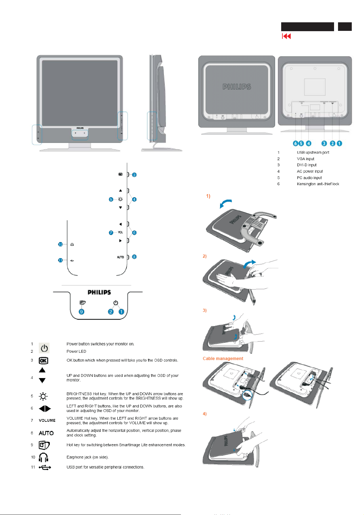
Frontview
Rear View
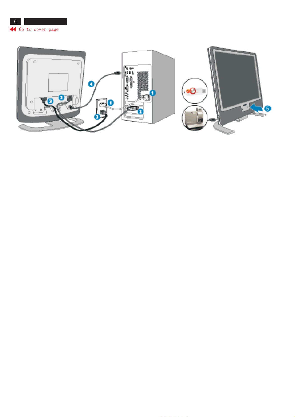
Connectingtoyour PC
If youuseanApple Macintosh, youneed to connect the specialMac
adapter to oneend of the monitor signal cable.
190X7&170X7 LCD
Connect to PC
1. Turn off your computer and unplug its power cable.
2. Connect the monitor signal cable to the video connector on the back of your computer
3. Plug the power cord of your computer and your monitor into a nearby outlet
4. USB plug
(a) Connect USB upstream port on monitor and the USB port on PC with a USB cable.
(b) The USB downstream port is now ready for any USB device to plug in
5. Turn on your computer and monitor. If the monitor displays an image, installation is complete.
Note: The USB plug is a pass through connection whether it can support USB 1.1 or USB 2.0 depends on your PC's
specification.
Connection to PC
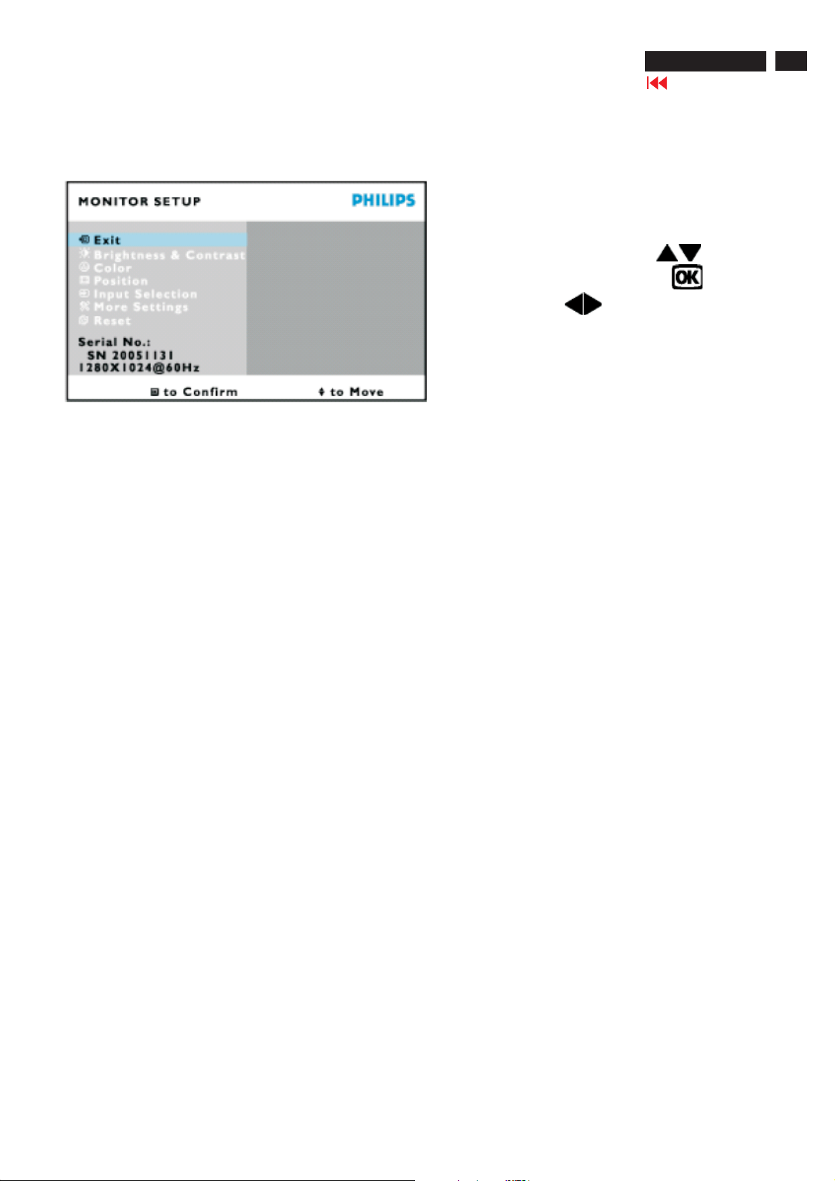
On Screen Display
On-ScreenDisplay(OSD)isa feature in all PhilipsLCDmonitors. Itallows an end user to adjust screen performance
or select functions of the monitorsdirectly through an on-screeninstructionwindow. A user friendly onscreendisplay
interf
ace is shown asbelow:
Basic and simple instruction on the control keys.
In the OSD shown above users can press
190X7&170X7 LCD
Go to cover page
buttons at the
7
front bezel of the monitor to move thecursor,
choice or change, and
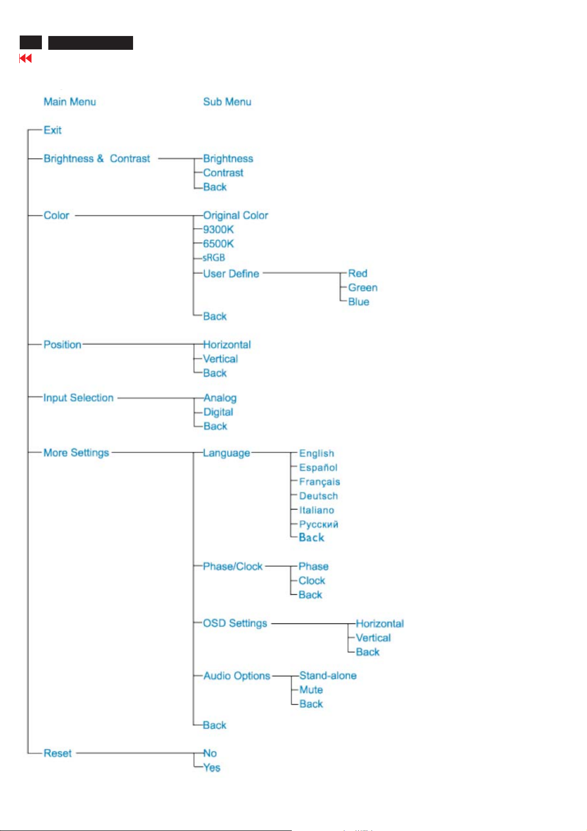
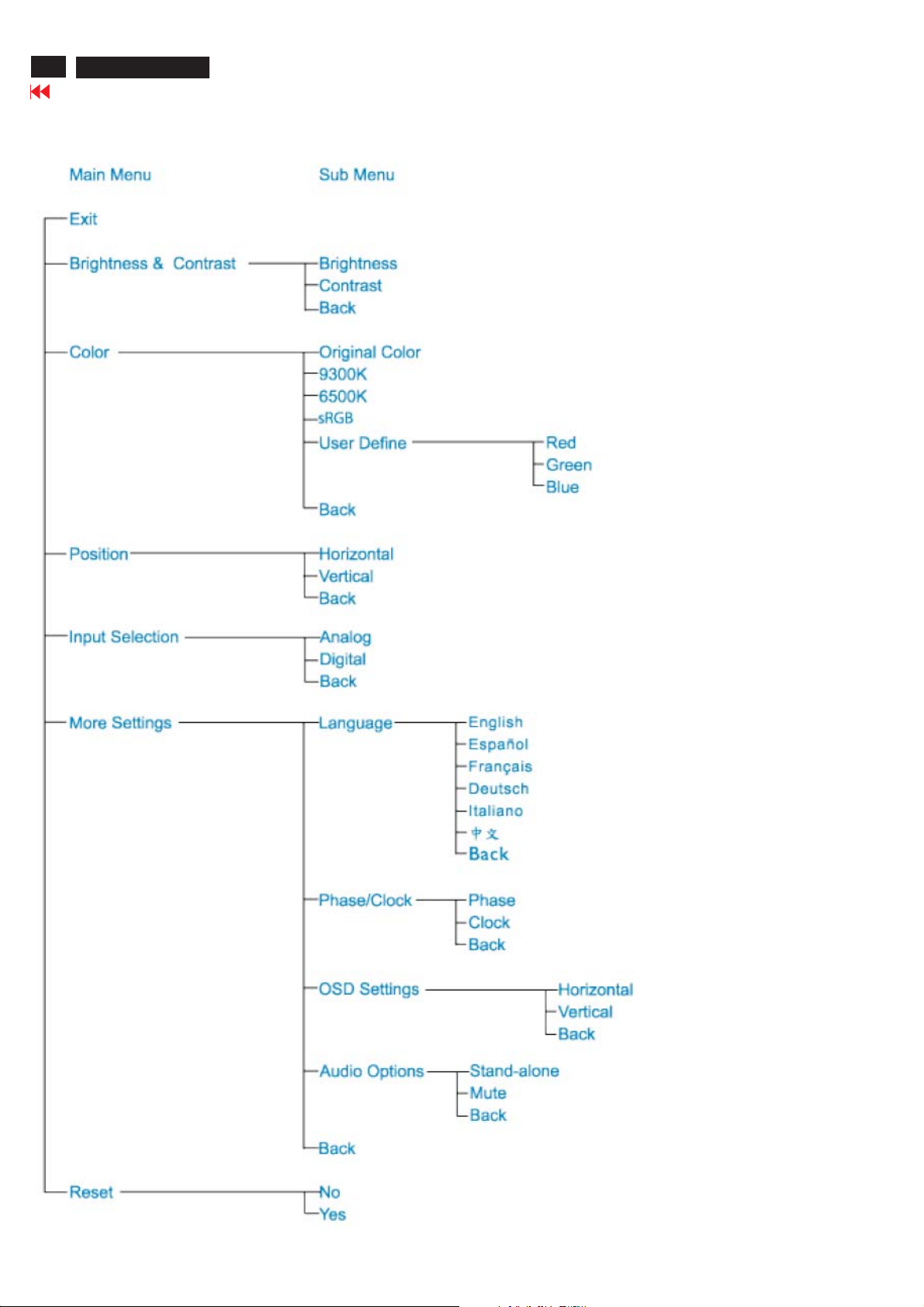
The OSD Tree(page8)
Belowisan overall view of the structure of the On-ScreenDisplay. You canusethis as areference whenyouwantto
workyour way around the differentadjustmentslater on.
Note: sRGBisa standardfor ensuring correct exchange of colorsbetweendifferent devices(e.g.digital cameras,
monitors, printers, scanners, etc.)
Usingastandard unified color space,sRGBwillhelp representpictures takenbya
onyour sRGB enabledPhilipsmonitors. In that way, thecolors are calibrated and you can rely on thecorrectness of
thecolorsshown onyour screen.
nsRGB compatible device correctly
to adjust/select thechange
to confirm the
Important with the useofsRGBisthat t
well as thecolor gamut.Therefore it is importanttoselect the sRGBsetting in the monitor's OSD.
To do so, open the OSD by pressingthe OK bu
and press OK again. Usetheright button to go to sRGB. Thenmove the down button and press OK again to exitthe
OSD.
After this, please do not change the brightness or co
monitor will exitthe sRGBmodeand go to a color temperature settingof 6500K.
he brightness and contrastofyour monitor is fixed toapredefinedsettingas
tton on the sideofyour monitor.Move the down button to go to Color
ntrast settingofyour monitor.Ifyou change either of these, the
8
190X7&170X7 LCD
Go to cover page
Only available for Europe Model
On Screen Display
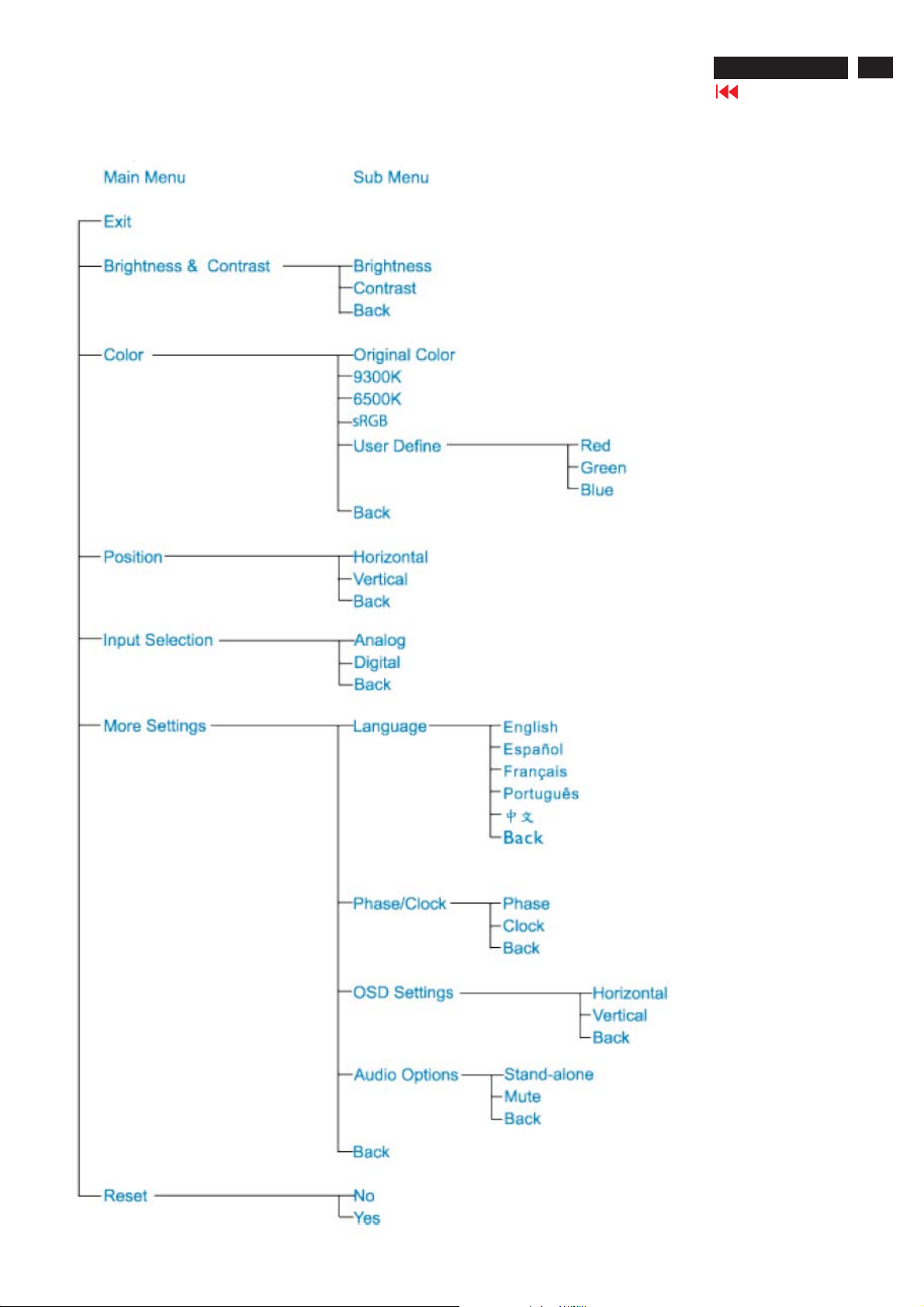
Only available for Nafta Model
On Screen Display
190X7&170X7 LCD
Go to cover page
9
10
190X7&170X7 LCD
Go to cover page
Only available for Asia Pacific Model
On Screen Display
OSD Lock/Unlock,Aging Mode
190X7&170X7 LCD
Go to cover page
11
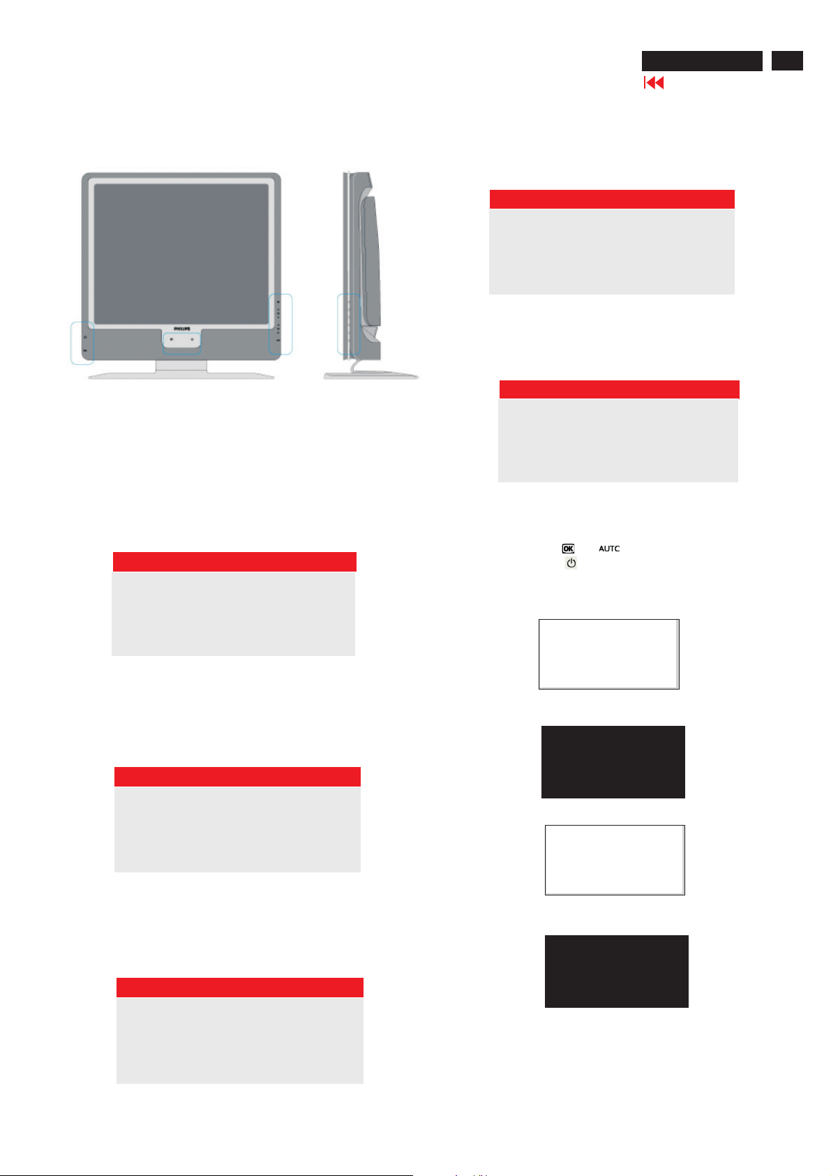
Front Control Panel
To Lock/Unlock OSD FUNCTION(User Mode)
The OSD function can be lockedbypressing"OK"button(1) for more
than 10 seconds, the screen shows following windows for 3seconds.
Everytime when you press"AUTO" or "OK" button, this message app-
ears on the screen automatically.
ATTENTION SIGNAL
CANNOT DISPLAY THIS VIDEO MODE..
This screen warnswhen the input frequencyfrom thecomputer is not
a standard video modeoroutof the monitor's scanning range.
Pleasechange the displaymodeof the operating software inthecom-
puter(i.e.windows) to 1280*1024@60HZfor
best display results.
ATTENTION SIGNAL
CANNOT DISPLAY THIS VIDEO
MODE,CHANGE COMPUTER DISPLAY
I
INPUT TO 1280*1024@60
HZ
WAIT FOR AUTOMATIC ADJUSTMENT
This screen appearswhen you press the "AUTO" buttons at the same
time.It will disappear when the monitor is properly adjusted
ATTENTION SIGNAL
WAITINGFOR AUTOMATIC ADJUSTMENT
Access Aging.. Mode
Step 1:Turn off LCD monitor, and disconnect Interface Cable
between Monitor and PC.
Step 2:[PushAUTO" "&" "buttons at the sametimeand
holdit]+[Press power ""button untilcomes out "AGING screen"
]=> then release all buttons.
OSD MAIN CONTROLS LOCKED
Unlock OSD function
Locked OSD function can be releasedbypressing "OK" button for more
than 10 seconds again
ATTENTION SIGNAL
OSD MAIN CONTROLS UNLOCKED
NO VIDEO INPUT
This screen appearsifthere is no video signal input. Pleasecheck that
the signal is properly connected to thevideo card of PC andmake sure
PCison
ATTENTION SIGNAL
Bring up:
AGING...
After 15 seconds, bring up:
After 15 seconds, bring up:
AGING...
After 15 seconds, bring up:
CHECK CABLE CONNECTION
----------
---------repeatly
Connect Signal cable again=> go back to normal display
12
190X7&170X7 LCD
Go to cover page
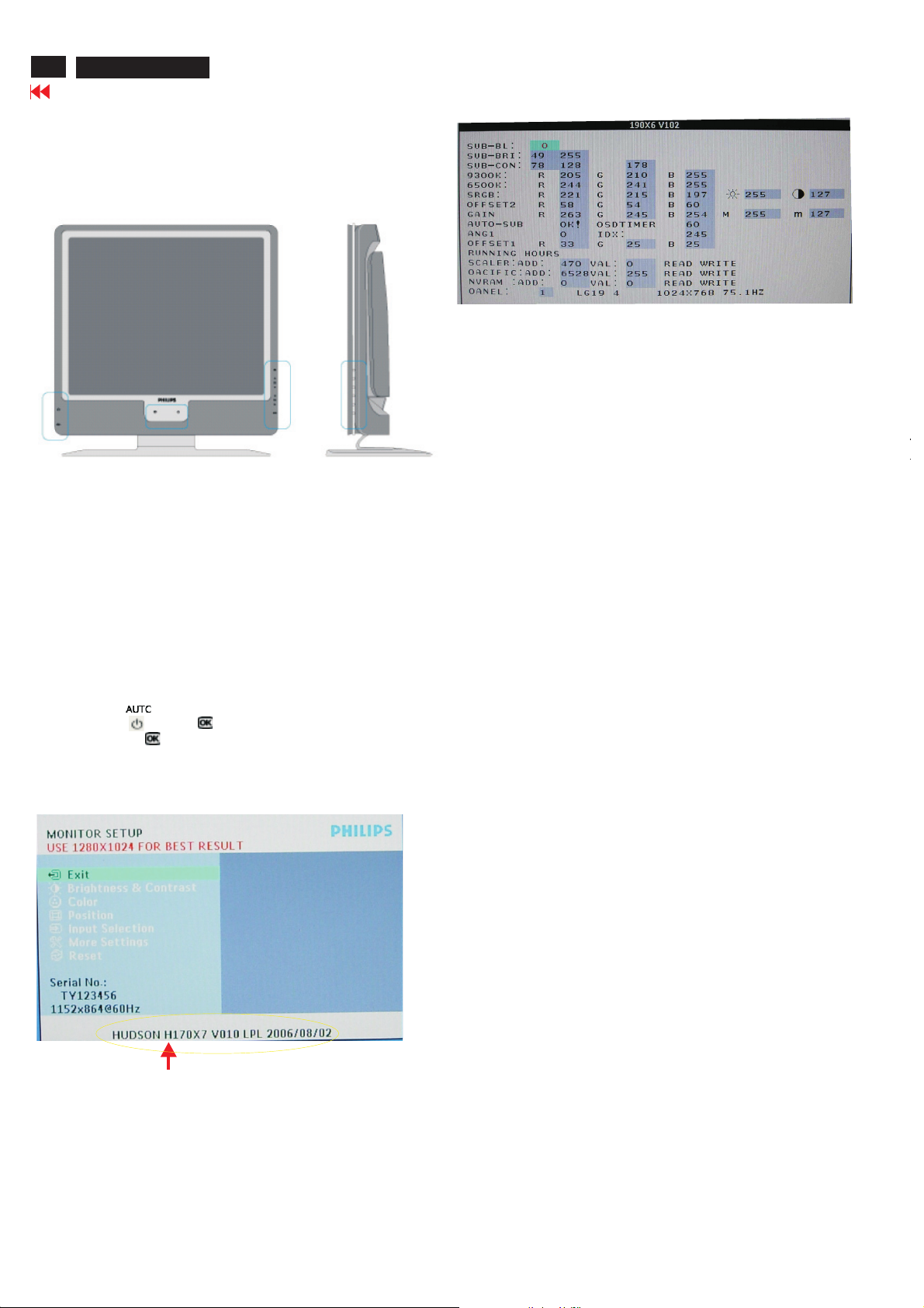
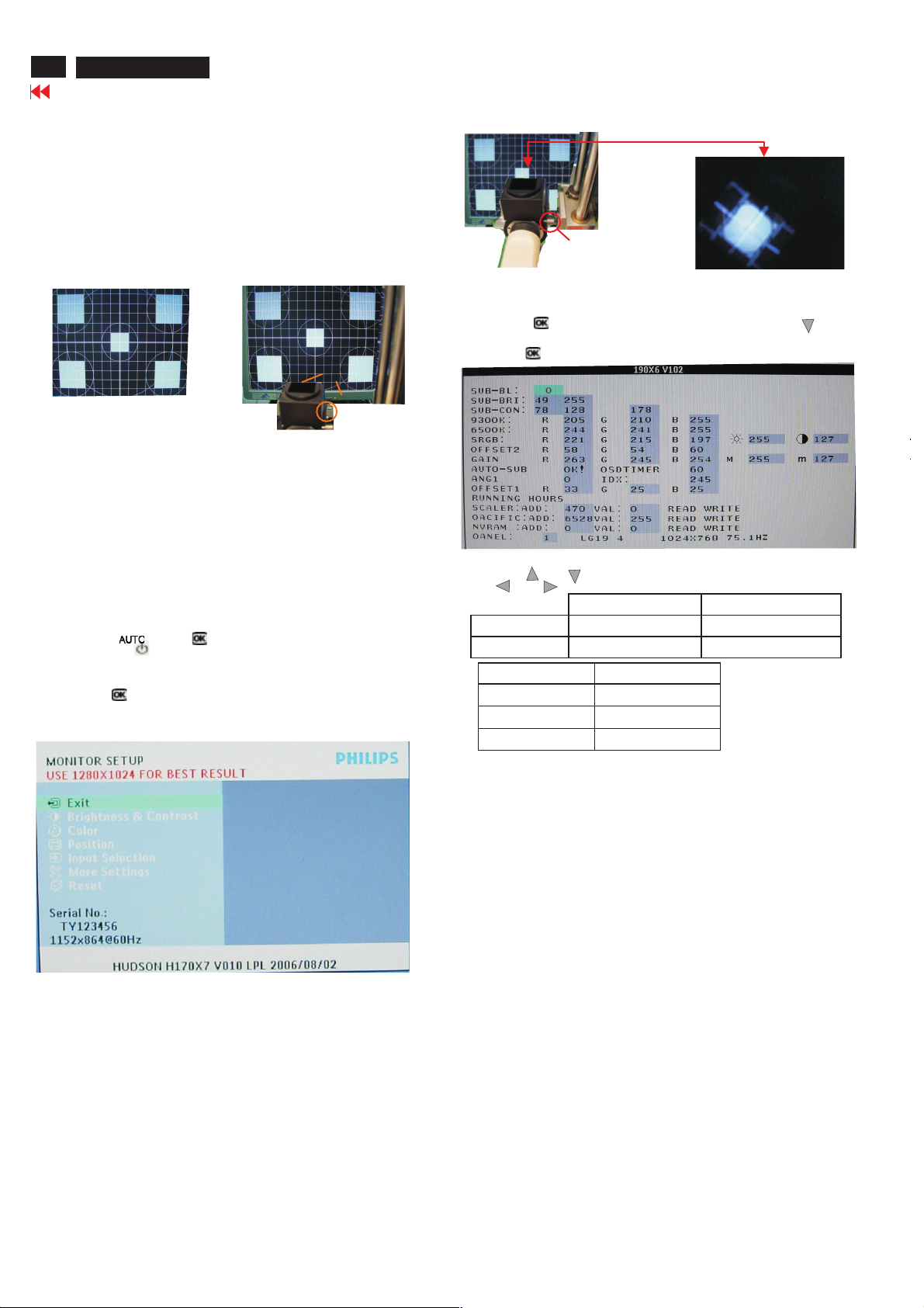
Front Control Panel
FacotryModel
BL : Blacklevel value
SUB-BRI : Brightness valuerange (Min Max)
SUB-CON : Contrast valuerange (Min Mid Max)
SRGB-B : Brightness ofsRGB
SRGB-C : ContrastofsRGB
Gain-m : Minimum valueofUser Gain
Gain-M : Maximum valueofUser Gain
AUTO-SUB: To do Auto color function when push M
OSDTIMER : OSD timeout control (sec)
ANG1 : For analog onlyproject control (0:Dual,1:Analog only)
IDX : Limit current ofinverter, 170X6: 200, 190X6: 245
SCALER : Read/Write scaler register
NVRAM : Read/Write eeprom address
Panel :LG(LG.Philips panel)
pattern
enukeyin white
Access FactoryMode
How to get into FactoryMode Menu
Step1:
Turn off monitor.
Step2:
[PushAUTO" "&OK" "buttons at the sametimeandholdit]
+[Press power ""button untill comes out "Windows screen"]
=> then release all buttons
Step3:
Press OK " " button,bringupFactorymo
inFig2.
FactoryMode indicator
FactoryMenu
Cursor can moveongraycolor area
Hot keyfunction:bypressing"up"and"DOWN"key
Simultaneously at User Mode (or FactoryMode)
(PS: The Offset RGBfunction can b
snowy noiseonthe backgroundwhen theresolution of video signal
is 1280*1024 vertical 60Hz. Slightlyincreaseordecreasethe value
until snowy noise completely disappear
de indication asshown
e used on reduceoreliminate
PixelDefect Policy
190X7&170X7 LCD190X7&170X7 LCD
Go to cover page
13
Philips' Flat PanelMonitors PixelDefect Policy
Philipsstrives to deliver the highest quality products. We use someof
the industry's mostadvancedmanufacturing processes and practice
stringent quality control. However, pixel or subpixeldefects on
LCD panels usedinflat panelmonitors are sometimesunavoidable.
No manufacturer can guarantee that all panels will be free from pixel
defects, but Philips guarantees that any monitor with anunacceptable
number ofdefects will b
This notice explains the differenttypes of pixeldefects and defines
acceptable defect levels for each type.Inorder to qualify for repairor
replacement under warranty, the number of pixeldefect
panel mustexceed these acceptable levels.
For example,no more than 0.0004% of the subpixels on a 15" XGA
monitor maybe defective.Furthermore, Philipssets evenhigher quality
standards for certain types or co
more noticeablethan others. This policyisvalid worldwide .
e repaired or replaced under warranty.
mbinations of pixeldefects that are
the TFT
s on a TFT LCD
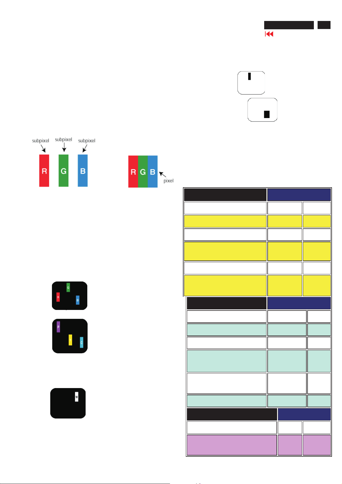
Pixels and Subpixels
A pixel, or picture element,iscomposed of three subpixels in the
primary colors of red, green and blue.Many pix
image.When all subpixels of apixel are lit, thethree colored subpixels
together appear as a single white pixel. When all are dark, thethree
colored subpixels together appear as a single black pixel.
Other combinati
other colors.
ons oflitand dark subpixels appear as singlepixels of
els together form an
Types of PixelDefects
Pixel and subpixeldefects appear on the screen in different ways.
There are two categories of pixeldefects and several types of subpixel
defectswithin each category.
Brig
ht Dot DefectsBright dot defects appear as pixels or subpixels that
are always litor"on".
These are thetypes ofbright dot defects:
BlackDot Defects
Blackdot defects appear as pixels or subpixels that are always dark or
"off".
These are thetypes ofblackdot defects:
One dark subpixel
Twoorthree adjacent dark subpixels
Proximity of PixelDefects
Becausepixel and subpixels defects of the sam
oneanother maybe more noticeable, Philips also specifies tolerances
for the proximity of pixeldefects.
etype that are nearby
PixelDefect Tolerances
In order to qualify for repairorreplacement duetopixeldefectsduring
the warranty period,
must have pixel or subpixeldefects exceedingthetolerances listedin
the followingtables.
BRIGHT DOT DEFECTS ACCEPTABLE LEVEL
MODEL
1lit subpixel 0 0
2 adjacent lit subpixels 0 0
3 adjacent lit subpixels (one white pixel) 0 0
Distance between two bright dot defects* 0 0
a TFT LCD panelina Philipsflat panelmonitor
170X6 190X6
170X7
190X7
One litred, green or blue subpixel
Twoadjacent lit subpixels:
-Red + Blue =Purp
-Red+Green=Yellow
- Green + Blue =Cyan (Light Blue)
Three adjacent lit subpixels
(one white pixel)
le
Totalbright dot defects of all types 0 0
BLACK DOT DEFECTS ACCEPTABLE LEVEL
MODEL
1darksubpixel 0 0
2 adjacent darksubpixels 0 0
3 adjacent darksubpixels 0 0
Distance between two blackdot
defects*
Totalblackdot defects of all types 0 0
TOTAL DOT DEFECTS ACCEPTABLE LEVEL
MODEL
Totalbrightorblackdot defects
of all types
170X6 190X6
170X7
00
170X6 190X6
170X7 190X7
0 0
190X7
14
190X7&170X7 LCD
Go to cover page
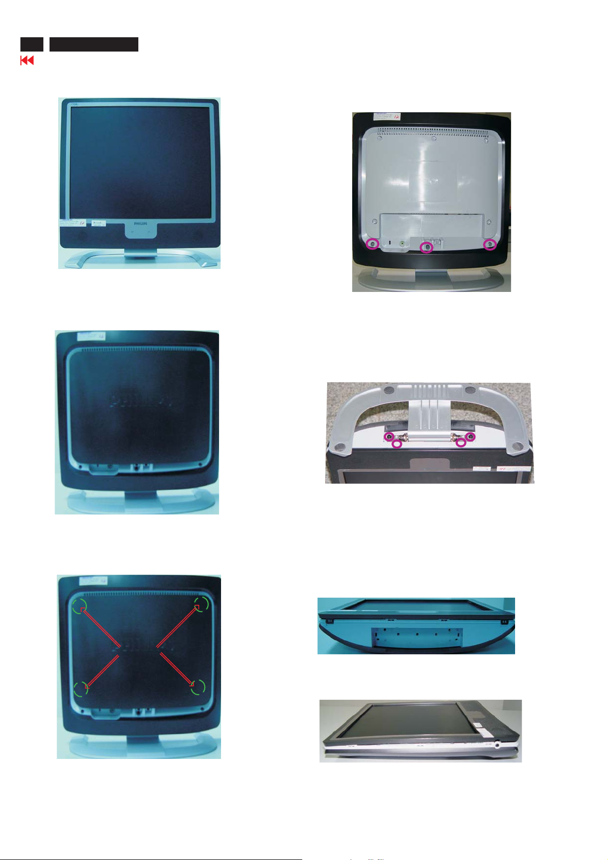
Mechanical Instructions
Front View
Back View
Step 2: Unscrew 3 screws as shown in Fig. 4.
Fig. 1
Fig. 4
Step 3:
-Unscrew the four screws as shown in Fig. 5.
- Remove the base.
Step 1: Use "l" type screwdriver to remove the Logo Cover as shown
in Fig. 3.
Clip
Fig. 3
Fig. 5
Step 4: Remove the front bezel
- Use thin "l" type screwdriver to open 4 clicks on bottom
side as shown in Fig. 6.
- Use thin "l" type screwdriver to open 3 clicks on right
and left side as shown in Fig. 7.
- Use thin "l" type screwdriver to open 4 clicks on top
side as shown in Fig. 8.
========>
======>
========>
Fig. 6
========>
======>
Fig. 7
========>
======>

Mechanical Instructions
Step 7: Unscrew 9 screws as shown in Fig. 11.
Disconnect 8 connectors as shown in Fig. 11.
190X7&170X7 LCD
Go to cover page
15
======>
Step 5: Remove the Back Cover Assy
-Remove the Control Board from the Back Cover Assy
-Unscrew 9 screws as shown in Fig. 9.
-Remove Audio Assy, Earphone Assy,two USB Assy and two LSP
Box from the Back Cover Assy
-Use thin "l" type screwdriver to open clicks on left side, right
side and up side, Remove LCD Panel from Back Cover Assy
shown in Fig. 9.as
<======
<======
=======>
Fig. 8
<======
======>
======>
<===
<======
LIPS(DELTA)
CONTROL ASSY
=======>
Fig. 11
Step 8:Unscrew 4 screws as shown in Fig.12.
Remove the metal frame
Fig. 12
=======>
SCALER ASSY
EARPHONE ASSY
USD ASSY
Step 6: Unscrew 14 screws as shown in Fig. 10.
Remove Shielding Cover
AUDIO ASSY
Fig. 10
Fig. 9
Fig.13
***************************************************************************
In warranty, it is not allowed to disassembly the LCD panel, even the
backlight unit defect.
Out of warranty, the replacment of backlight unit is a correct way
when the defect is cused by backlight (CCFL,Lamp).
***************************************************************************
16
190X7&170X7 LCD
Display Adjustment
Go to cover page
Alignment procedure
1. Turn on the LCD monitor.
2.Turn on the Timing/pattern generator. See Fig.1
Resolution :1280x1024(Use the best resolution)
Timing : H= 31.47KHz V=60Hz
3. Preset LCD color Analyzer CA-110
-Remove the lens protective cover of probe CA-A30.
-Set measuring/viewing selector to measuring position for reset
analyzer.(zero calibration) as Fig.2
- Turn on the color analyzer (CA-110)
-Press 0-CAL button to starting reset analyzer. See Fig.3
Cover (black)Cover (black)
Measurement viewing selectorMeasurement viewing selector
Clear imageClear image
Measurement/viewing selectorMeasurement/viewing selector
Fig.4
10. Setting pattern to full white picture
11. Press button, then select factory mode indicator by"" ""
button
12. Press""button to bring up submenu windows as below:
Fig. 1
Fig. 2
4. Access Factory Mode
How to get into Factory Mode Menu
Step1:
Turn off monitor.
Step2:
[Push AUTO" "&OK ""buttons at the same time and hold it]
+[Press power ""button untill comes out "Windows screen"]
=> then release all buttons
Step3:
Press OK ""button, bring up Factory mode indication as shown
in Fig3.
13. Press ""or ""button to select R GB. Change the value by
""or ""key until the X,Y co-ordinates as below
9300°K6500°K
x (center) 0.283 ± 0.0200.313 ± 0.020
y (center) 0.297 ± 0.0200.329 ± 0.020
sRGB
x(center) 0.313 ± 0.020
y(center) 0.329 ± 0.020
Ynits 180 ± 10
Alignment hits: 1. R for x value,Gfor y value,Bfor Y value on the
15. EEPROMpresetting(B)
After finishing all the adjustment, set:
Brightness control to 100%
Contrast control to 50%
OSD position at middle of screen
COLORadjusts to 6500K color.
colour analyzer.
2. If the colour analyzer has been calibrated and preset
colour temperature in it. Please switch to correct
setting in accordance with colour settings.
Fig. 3
Note: after alignment, please reset OSD to user s mode for normal
operation. Otherwise, the monitor won t entering power saving mode
and showing full white picture all the time as no video signal supplied.
To leave factory mode by restart the monitor.
5.Adjust OSD menu to lower position of screen (i.g. adjust V-position to
value "0"at submenu of OSD Setting.
6. Setting Brightness and Contrast
-Adjust Brightness to value "90".
-Adjust Contrast to value " 80" .
7. Switch light probe to Viewing position.
8. Move the Lens barrel forward or backward to get clear image as
showninFig.4
9. Switch light probe to Measuri ng position. It should be able to indicate
Trouble Shooting
190X7&170X7 LCD
Go to cover page
17

190X7&170X7 LCD
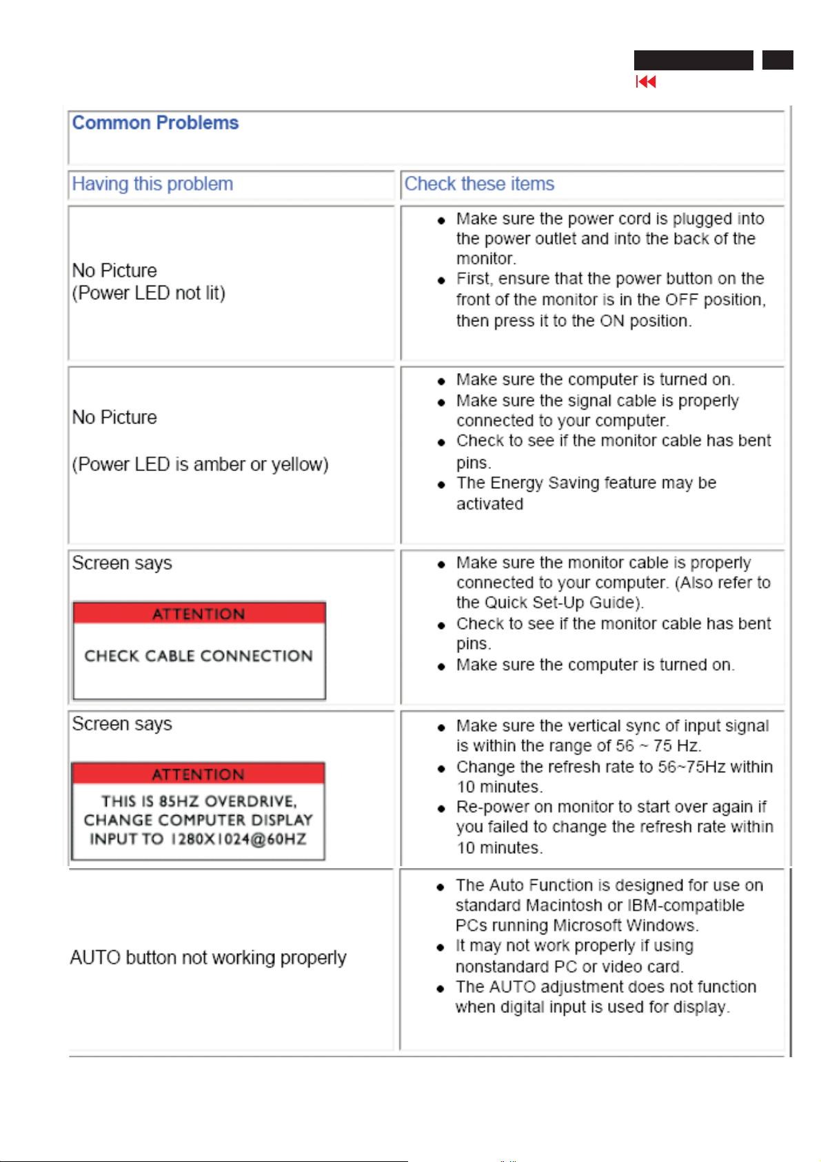
Trouble Shooting
'

Warning message
ItemAttentionSignals DisplayTime ConditionAttention off
190X7&170X7 LCD
Go to cover page
19
1Cannot display this
video mode, change
computer displayinput
to 1280x1024@60Hz
2 NO VIDEO INPUT 30.mins This message appearswhen
3 CHECK CABLE
CONNECTION
4Enter sleep mode 3secsThismessage appearswhen
5Waiting for automatic
adjustment
6Use 1280x1024 for best
result
7OSDmain controls
locked
30 mins This warning appearswhen the
input signalfromyourcomputer
is not in a standard video mode
or is outof the monitor s
scanningra
monitor enterssleeping mode.
there is no signalinput but with
cable while AC or DC power on.
After 30 mins, monitor enters
sleeping mode
30 mins This message appearswhen a
signal cable is disconnected
while monitor is working.After
30 mins, monitor enterssleeping
mode.
monitor is abouttoenter power
saving mode
Till automatic
adjustment
finished
On top of
OSD main
menu
3secs/or till
OSD main
controls
unlocked
appear
This message is displayedwhen
auto adjustment buttonis
pressed. It disappearswhen
auto adjustments are completed
This message will showupat
thetopof the OSD main menu in
red color when the input
resolutionisnot the 1280x1024
This message will appear 3
seconds to indicate the OSD
MAIN CONTROLS status when
to lock or un-lockit by pressing
MENU(OK) buttonfor more
than10seconds whilethere is
video input fromPC.This
function provides th
that user canlock all the OSD
main controlincase user don’t
wantthe FOS performance
settingtobechanged, for
instance,duringcommercial
exhibition.
nge.After 30 mins,
ealternative
20
190X7&170X7 LCD
Go to cover page
Warning Message
8 OSD MAIN CONTROLS
9 THISIS85HZ
10 the window of
11 the w indow of
12 SELECTED INPUT NOT
13 SECURITY
UNLOCKED
OVERSCAN, CHANGE
COMPUTER DISPLAY
INPUT TO
1280X1024@60HZ
"" ""
MONITOR SETUP
""
BRIGHTNESS
"
AVAILABLE
PROTECTED, THIS
MONITOR IS GOING
TO ENTER POWER
SAVING MODE IN 15
SECONDS
"
3 secs This message will appear 3
10 mins This message will appear 5
60 secs This message will appear when
60 secs This message will appear when
3 secs When just one input (analog or
15 secs This warning appears when the
seconds to indicate the OSD
MAIN CONTROLS status when
to un-lock it by pressing
""
MENU(OK) button for more
than 10 seconds while there is
video input from
PC
seconds in every 60 seconds for
10 minutes when the input of PC
video timing is at 85Hz mode.
Remark: AUTO is still functional
in this mode
the OK button is pressed.
the BRIGHTNESS button is
pressed.
digital), press input switch or
hot key, then after show this
warning message 3 sec, return
to original input.
security was set ON and
someone takes out from the
client PC
""
14 SECURITY
15 the window of
PROTECTED, THIS
MONITOR IS GOING
TO ENTER POWER
SAVING MODE IN 15
SECONDS
""
VOLUME
1 mins This warning appears when
Asset management Server
sends power saving command
to client PC
60 secs This message will appear when
the VOLUME button is pressed.
Electrical instructions(190X7)
190X7&170X7 LCD
Go to cover page
21
1. General points
1.1 Duringthetestand measuring,supply a distortionfree AC
1.2 All measurementsmentionedhereafter are carried outata
1.3 All voltages are to be measured or appliedwith respect to
1.4 Thetest has to be d
1.5 All valuesmentionedinthesetest instruction are only
1.6 The letterssymbols (B) and (S) placedbehind thetest
instructiondenotes
1.7 The white balance (color temperature)has to betestedin
subduedlighted room.
1.8 Repetitive power on/off cycleareallowed except it should be
avoidedwithin6sec.
2. Input signal
2.1 Si gnal type
2.1.1 Video signalinput
2.1.2 Sync signalinput
2.2 Input signalmode
#ResolutionH-FrequencyPixel rate V-FrequencyComment
mains voltage to the apparatus viaanisolated transformer
withlowinternal resistance.
normalmains voltage (90 - 132 VAC for USA
264 VAC for EUROPEAN version, or 90 - 264 VAC for the
modelwithfullrange power supply, unless otherwise
stated.)
ground, unless otherwise stated.
Note:don't use heat-sink as ground.
panel after 30 minuteswarm-upatleast in aroomwith
temperature of25+/-5degree C.
applicableof a well
aligned apparatus, with correct signal.
(B): carried out 100% inspection at assembly line
(S): carried outtest by sampling
Signalsource: pattern generator format as attachment.
(Table 1 to 39) Reference generator:QuantumData
802G
The input signals canbeappliedintwo different
modes:
1). VESA Analog
Thevid
signals. Thevideo signals
are analog levels, where 0V corresponds to black
and 700mV is the maximum
signal amplitude.Input impedance of video pins is
75 ohm +/- 1%.
2). IntelDVIDigital
Input signa
The capability ofsync signalinputsshall include
separate sync, composite syncand
syncon green. input impedance:2k2ohms
Thesignalare defined asfollow:
Separate sync TTL level, P
Composite sync TTL level, Positive/Negative
Syncon green H-sync TTL level, Positive/Negative
Signalsource: pattern generator format as attachment
(Table 1 to 39)
Reference generator:QuantumData 802G
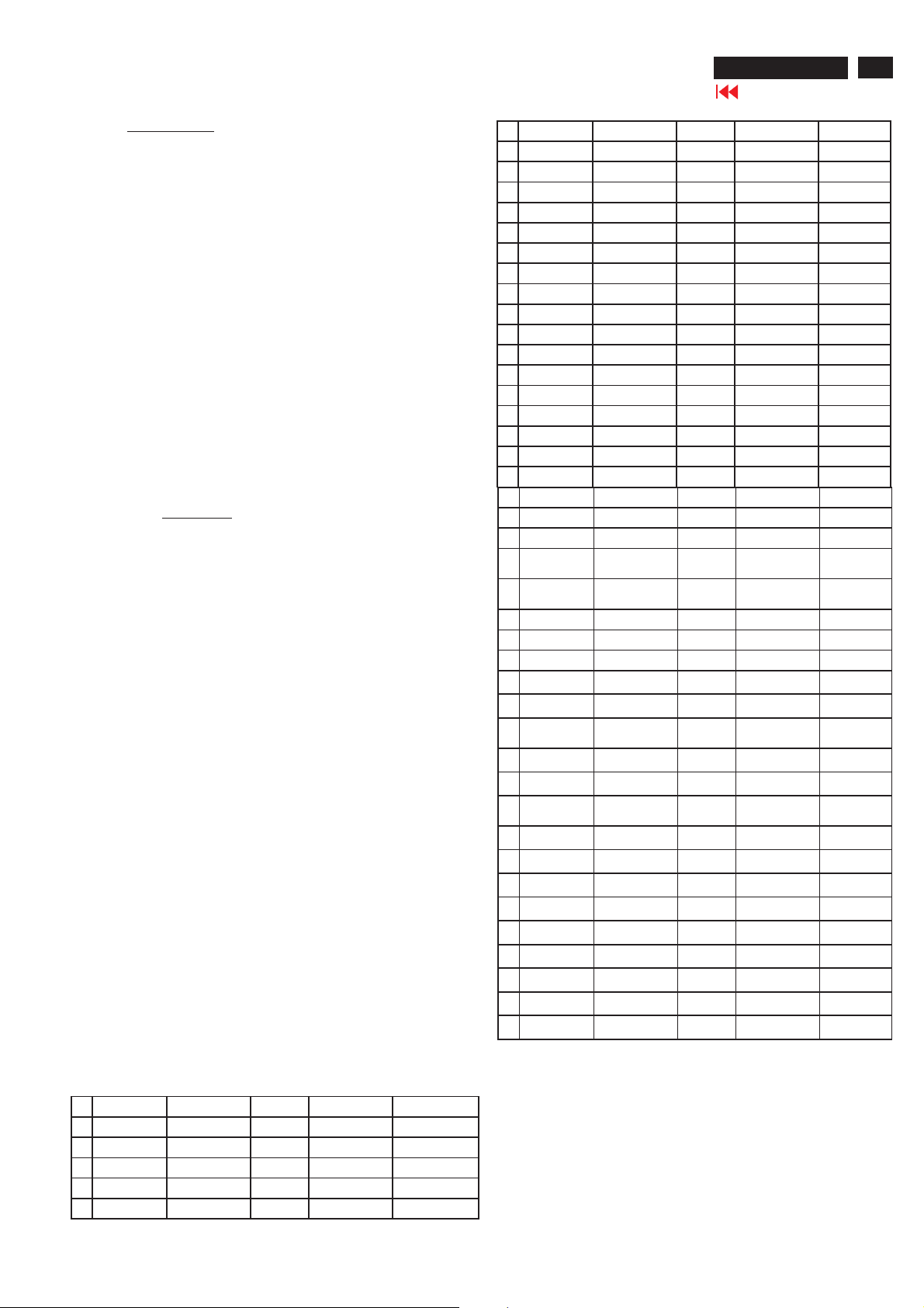
Pre-set 39 modes
PRESET VIDEO RESOLUTION
1 640X350 31.5K 25.175 70Hz IBM VGA10h
2 720X400 31.5K 28.322 70Hz IBM VGA3h
3 640X480 31.5K 25.175 60Hz
4 640X480 35.0K 30.24 67Hz
oneon acomplete set including LCD
eo inputconsists of red, green, and blue
l: FourchannelTMDSsignals
version, 195 -
ositive/Negative
5 640X480 37.9K 31.5 72Hz
6 640X480 37.5K 31.501 75Hz
7 640X480 43.3K 36 85Hz
8 800X600 35.2K 36 56Hz
9 800X600 37.9K 40 60Hz
10 800X600 48.1K 50 72Hz
11 800X600 46.9K 49.498 75Hz
12 800X600 53.7K 56.251 85Hz
13 832X624 49.7K/ 57.28 75Hz MAC
14 1024X768 48.4K 65 60Hz
15 1024X768 56.5K 75 70Hz
16 1024X768 60.0K 78.75 75Hz
17 1024X768 61.1K 83.096 76Hz IBM XGA-2
18 1024X768 68.7K 94.5 85Hz
19 1152X864 54.0K 79.9 60Hz Non-VESA
20 1152X864 63.9K 94.5 70Hz Non-VESA
21 1152X864 67.5K 108 75Hz
22 1152X870 68.7K 100 75Hz MAC
23 1152X900 61.8K 92.94 66Hz SUN Mode
24 1152X900 71.8K 108 76Hz SUN Mode
25 1280X960 60.0K 108 60Hz
26 1280X960 75.0K 129.895 75Hz Non-VESA
27 1280X1024 64.0K 108 60Hz
28 1280X1024 71.7K 117 67Hz SUN Mode
29 1280X1024 76.0K 130.223 72Hz DOS/V
30 1280X1024 80.0K 135 75Hz
31 1280X1024 81.1K 135.008 76Hz SUN Mode
32 960X720 44.8K 57.58 60Hz
33 960X720 56.4K 72.42 75Hz
34 1280X720 44.8K 74.5 60Hz
35 1280X720 52.5K 89.04 70Hz
36 1280X720 56.5K 95.75 75Hz
37 1280X768 47.8K 79.5 60Hz
38 1280X768 56K 94.976 70Hz
39 1280X768 60.3K 102.25 75Hz
Remark1: The 19 timing modesinBlueand Bold texts represent
FactoryPreset modes
Remark2: Other modes can pass withfairperformance.
Remark3: If 1280x720 and 960x720 cannot b
1280x720 is preferred.
Remark4: If 1280x768 and 1024x768 cannot be distinguished
then 1024x768 is preferred
whichneed to beensured perfect performance.
e distinguished then
.
IV
II
V
I
22
190X7&170X7 LCD
Go to cover page
Electrical instructions(190X7)
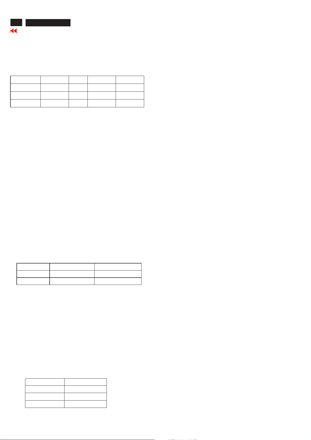
2.3 Allowed 85 Hz overscan signal mode specified
Once the signal input of PC is 85Hz, this monitor is able to
display at least for
10 minutes. An attention signal appears and shows "THIS
IS 85HZ OVERDRIVE, CHANGE COMPUTER DISPLAY INPUT TO
1280X1024 @ 60 HZ"
Dot rate (MHz) H. Freq (K Hz) Mode Resoluti on V. Freq (Hz)
36.000 43.269 VESA 640 * 480 85.008
5 56.250 53.674 VESA 800 * 600 85.061
94.500 68.677 VESA 1024 * 768 84.997
3. Power Supply (S)
Setup the AC I/P at 90VAC, and Output DC loading at 12V 3.7 Amp,
5V 2.1 Amp,
The DC output voltages are 5V ± 0.25V and 12V± 1.2V.
4. Di splay A djustment
4.1 Access to factory mode (RS232) in auto-alignment system
The communication protocol switch to RS232 .
4.2 Auto color adjustment (B)
Apply timing 1280*1024 /60 Hz with 32 gray pattern.
Set brightness to 100% and contrast to 50%.
Alignment program will adjust R/G/B offset and gain to
calibrate the color automatically.
After finishing the adjustment, check the color performance with
64-gray level pattern.
The adjacent levels should be distinguishable.
Check Factory Preset 19 modes.
4.3 Adjustment of WHITE-D (B)
4.3.1 Use Minolta CA-110 for color coordinates check:
Apply timing 1280*1024 /60 Hz with white pattern.
Set brightness control to100% and contrast control to
50%.
Adjust the R, G, B Sub-gain, for the screen center,
the 1931 CIE chromaticity (X, Y) coordinates shall be
4.5 EEPROM presetting (B)
4.6
After finishing all the adjustment need to reset:
"Brightness" to 100%
"Contrast" to 50%
"OSD position" at middle of screen
"Color" to Original color temperature
"Stand-Alone" set to Off
"Mute" set to Off
Remark : Color temperature default setting depends on the
region of the model.
For European (/00) and NAFTA/LATAM (/27)
models, it is Original color
For APMEA model (/69,/75,/93,/96,/97), it is
9300°K
For LATAM (Manaus production) model (/78), it is
6500°K
9300°K 6500°K
x (center) 0.283 ± 0.005 0.313 ± 0.005
y (center) 0.297 ± 0.005 0.329 ± 0.005
4.3.2 Use Minolta CA-110 for luminance check:
Apply timing 1280*1024 /60 Hz with white pattern.
Set brightness control to 100% and
contrast control to100% to check the luminance in
the center of the screen.
(1) >= 250 Ni t for Original Color
(2) 215 ± 10 Nit for 6500°K
4.4 Adjustment of sRGB
Apply a 1280*1024 / 60Hz signal with white pattern, set
brightness to 100%, and
contrast to 50%. Adjust the R, G, B Sub-Gain, for the screen
center, the 1931 CIE
chromaticity (X, Y) co-ordinates shall be;
sRGB
x(center) 0.313 ± 0.005
y(center) 0.329 ± 0.005
Ynits 180 ± 10
Electrical instructions(170X7)
190X7&170X7 LCD
Go to cover page
23
1. General points
1.1 Duringthetestand measuring,supply a distortionfree AC
mains voltage to the apparatus viaanisolated transformer
withlowinternal resistance.
1.2 All measurementsmentionedhereafter are carried outat
a normalmains voltage (90 - 132 VAC for
USA version,
195 -264 VAC for EUROPEAN version, or 90 - 264 VAC
for the modelwithfullrange power supply, unless
otherwise stated.)
1.3 All voltages are to be measured or appliedwith respect to
ground, unless otherwise stated.
Note:don't use heat-sink as ground.
1.4 Thetest has to b
e doneon acomplete set including LCD
panel after 30 minuteswarm-upatleast in aroomwith
temperature of25+/-5degree C.
1.5 All valuesmentionedinthesetest instruction are only
applicableof a well
aligned apparatus, with correct sign
al.
1.6 The letterssymbols (B) and (S) placedbehind thetest
instructiondenotes
(B): carried out 100% inspection at assembly line
(S): carried outtest by sampling
1.7 The white balance (color temperature)has to betestedin
subduedlighted
room.
1.8 Repetitive power on/off cycleareallowed except it should be
avoidedwithin6sec
2. Input signal
2.1 Si gnal type
2.1.1 Video signalinput
Signalsource: pattern generator format as attachment.
(Table 1 to 39) Reference generator:QuantumData
802G
The input signals canbe appliedintwo different
modes:
1). VESA Analog
eo inputconsists of red, green, and blue
Thevid
signals. Thevideo signals
are analog levels, where 0V corresponds to black and
700mV is the maximum
signal amplitude.Input impedance of video pinsis75
ohm +/- 1%.
2). IntelDVIDigital
Input signa
l: FourchannelTMDSsignals
2.1.2 Sync signalinput
The capability ofsync signalinputsshall include
separate sync, composite syncand
syncon green. input impedance:2k2ohms The signals
are defined asfollow:
Separate sync TTL level, Po
sitive/Negative
Composite sync TTL level, Positive/Negative
Syncon green H-sync TTL level, Positive/Negative
Signalsource: pattern generator format as attachment
(Table 1 to 39)
Reference generator:QuantumData 802G
2.2 Input signa
lmode
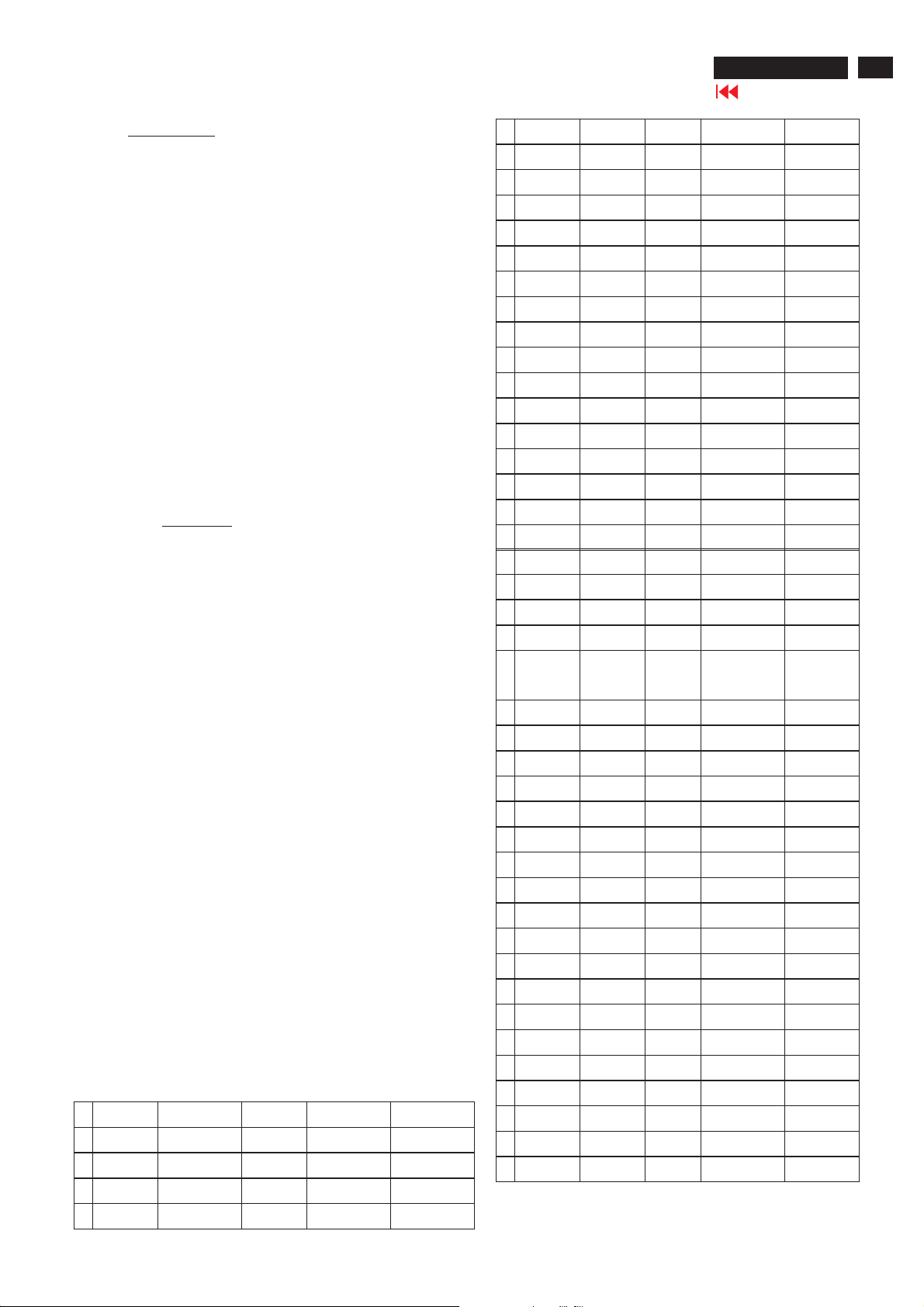
Pre-set 39 modes
PRESET VIDEO RESOLUTION
#ResolutionH-FrequencyPixel rate V-FrequencyComment
1 640X350 31.5K 25.175 70Hz IBM VGA 10h
2 720X400 31.5K 28.322 70Hz IB M VGA3h
4 640X480 35.0K 30.24 67Hz
5 640X480 37.9K 31.5 72Hz
6 640X480 37.5K 31.501 75Hz
7 640X480 43.3K 36 85Hz
8 800X600 35.2K 36 56Hz
9 800X600 37.9K 40 60Hz
10 800X600 48.1K 50 72Hz
11 800X600 46.9K 49.498 75Hz
12 800X600 53.7K 56.251 85Hz
13 832X624 49.7K/ 57.28 75Hz MAC
14 1024X768 48.4K 65 60Hz
15 1024X768 56.5K 75 70Hz
16 1024X768 60.0K 78.75 75Hz
17 1024X768 61.1K 83.096 76Hz IBM XGA-2
18 1024X768 68.7K 94.5 85Hz
19 1152X864 54.0K 79.9 60Hz Non-VESA
20 1152X864 63.9K 94.5 70Hz Non-VESA
21 1152X864 67.5K 108 75Hz
22 1152X870 68.7K 100 75Hz MAC
23 1152X900 61.8K 92.94 66Hz SUN Mode
IV
24 1152X900 71.8K 108 76Hz SUN Mode II
25 1280X960 60.0K 108 60Hz
26 1280X960 75.0K 129.895 75Hz Non-VESA
27 1280X1024 64.0K 108 60Hz
28 1280X1024 71.7K 117 67Hz SUN Mode V
29 1280X1024 76.0K 130.223 72Hz DOS/V
30 1280X1024 80.0K 135 75Hz
31 1280X1024 81.1K 135.008 76Hz SUN Mode I
32 960X720 44.8K 57.58 60Hz
33 960X720 56.4K 72.42 75Hz
34 1280X720 44.8K 74.5 60Hz
35 1280X720 52.5K 89.04 70Hz
36 1280X720 56.5K 95.75 75Hz
37 1280X768 47.8K 79.5 60Hz
38 1280X768 56K 94.976 70Hz
39 1280X768 60.3K 102.25 75Hz
3 640X480 31.5K 25.175 60Hz
24
190X7&170X7 LCD
Go to cover page
Electrical instructions(170X7)
Remark1: The 19 timing modes in Blue and Bold texts represent Fact ory
Preset modes
which need to be ensured perfect performance.
Remark2: Other modes can pass with fair performance.
Remark3: If 1280x720 and 960x720 can not be distinguished then
1280x720 is preferred.
Remark4: If 1280x768 and 1024x768 can not be distinguished then
1024x768 is preferred.
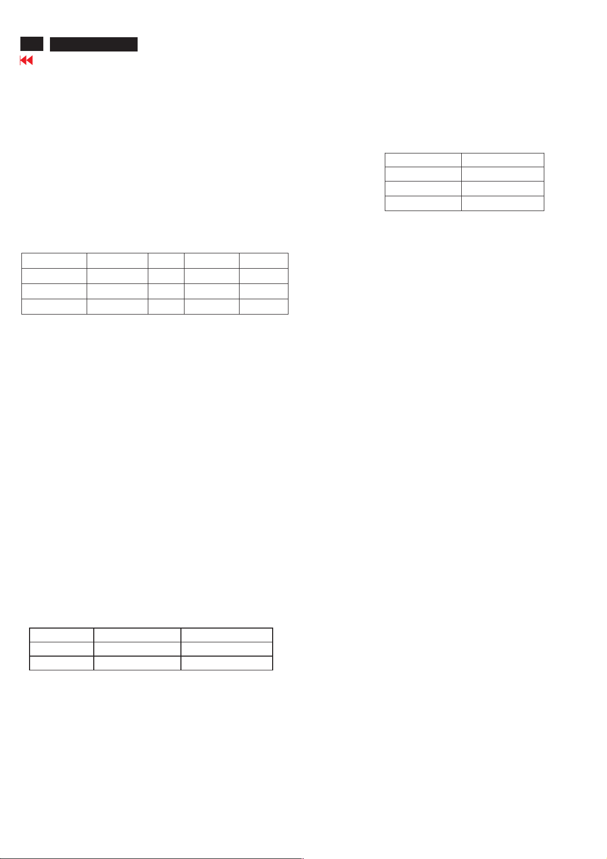
2.3 Allowed 85 Hz overscan signal mode specified
Once the signal input of PC is 85Hz, this monitor is able to display
at least for
10 minutes. An attention signal appears and shows "THIS IS
85HZ OVERDRIVE, CHANGE COMPUTER DISPLAY INPUT TO
1280X1024 @ 60 HZ"
Dot rate (MHz) H. Freq (KHz) Mode Reso lutio n V. Freq (Hz)
36.000 43.269 VESA 640 * 480 85.008
56.250 53.674 VESA 800 * 600 85.061
94.500 68.677 VESA 1024 * 768 84.997
3. Power Supp ly (S)
Setup the AC I/P at 90VAC, and Output DC loading at
12V 3.7 Amp, 5V 2.1 Amp,
The DC output voltages are 5V ± 0.25V and 12V± 1.2V.
4. Di splay A djustment
4.1 Access to factory mode (RS232) in auto-alignment system
The communication protocol switch to RS232 .
4.2 Auto color adjustment (B)
Apply timing 1280*1024 /60 Hz with 32 gray pattern. Set
brightness to 100%
and contrast to 50%.
Alignment program will adjust R/G/B offset and gain to
calibrate the color automatically.
After finishing the adjustment, check the color performance
with 64-gray level pattern.
The adjacent levels should be distinguishable.
Check Factory Preset 19 modes.
4.3 A djust ment of WHITE-D (B)
4.3.1 Use Minolta CA-110 for color coordinates check:
Apply timing 1280*1024 /60 Hz with white pattern.
Set brightness control to 100% and contrast control to
50%.
Adjust the R, G, B Sub-gain, for the screen center,
the 1931 CIE chromaticity (X, Y) coordinates shall be
4.4 Adjustment of sRGB
Apply a 1280*1024 / 60Hz signal with white pattern, set
brightness to 100%, and
contrast to 50%. Adjust the R, G, B Sub-Gain, for the screen
center, the 1931 CIE
chromaticity (X, Y) co-ordinates shall be;
sRGB
x(center) 0.313 ± 0.005
y(center) 0.329 ± 0.005
Ynits 180 ± 10
4.5 EEPROM presetti ng (B)
4.6
After finishing all the adjustment need to reset:
"Brightness" to 100%
"Contrast" to 50%
"OSD position" at middle of screen
"Color" to Original color temperature
"Stand-Alone" set to Off
"Mute" set to Off
Remark : Color temperature default setting depends on the
region of the model.
For European (/00) and NAFTA/LATAM (/27)
models, it is Original color
For APMEA model (/69,/75,/93,/96,/97), it is
9300°K
For LATAM (Manaus
production) model (/78), it is 6500°K
9300°K6500°K
x (center) 0.283 ± 0.005 0.313 ± 0.005
y (center) 0.297 ± 0.005 0.329 ± 0.005
4.3.2 Use Minolta CA-110 for luminance check:
Apply timing 1280*1024 /60 Hz with white pattern. Set brightness
control to 100% and
contrast control to100% to check the luminance in the center of
the screen.
(1) >= 250 Ni t for Original Color
(2) 215 ± 10 Nit for 6500°K
Smartlmage Lite
190X7&170X7 LCD
Go to cover page
Introduction
PhilipsSmartlmage Lite Featureswith PhilipsLightFrame Technology to enhance your frontofscrennperformance depend by contenttype.It is
changing brightness or contrast profiles to enr
image or video,you can always get bestviewingexperience from PhilipsSmartlmage Lite.
How to enable smartlmage lite
ich color ofimage and sharpentest.No matter your applicationison test processingorwatching
25
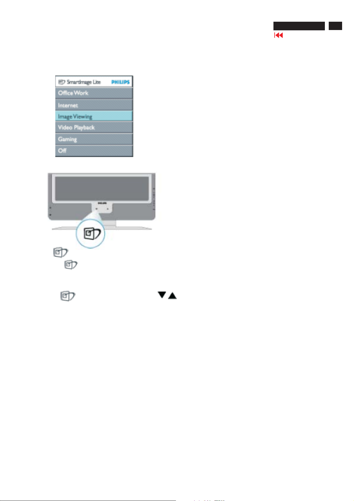
1.Press to launch the Smartlmage Lite onscreen display.
2.Keep press to toggle bwteenOffice Work,Internet,Image Viewing,Video Playback,Gaming,and Off.
3.The Smartlmage Lite onscreen display will remain onscreenfor 5second or you can also press OK to mak
Except using key to scroll down,you can also press buttons to chooseand press Ok to confirmselection and closeteSmartlmage
Lite OSD.
econfirmation.
There are six modes to be selected:
Office work
1. :Select this mode for general office application,like word processing,spreadsheet,and email.the screenisdominatedby test.
Internet
2. :Select this mode for Internet application,especially webbrowsing.The screenismixedbytestand picture.
.Image Viewing
3:S
Video Playback
4. :Select this mode for video application,like Microsoft Mdeia Player or RealPlayer.The screenisdominatedbyvideo.
Gaming
5. :Select this mo
6. :No optimizationbySmartimage Lite.
Off
elect this mode for image viewing application.especially in slid show.the screenisdominatedbypicture.
de for PC game software.The screenisdominatedbyartifivial animationwith rich color.
26
,
190X7&170X7 LCD
SmartManage
Go to cover page
Introduction
Philips SmartManage is an advanced solution for users, corporate/institution
IT administrator in
particular, to manage their Philips monitors as part of the asset management
environment. The
solution includes three essential components, Philips SmartManage
Administrator, and Philips
SmarControl and Agent.
Philips SmartManage is a solution joint developed by Philips and Altiris Inc.
Smar tManage Featu res an d Benefi ts
The Philips SmartManage is a working console for IT management to gather
monitors assets
information, run asset report, control assets security, monitor assets security,
and issue instant
messages to monitor users.
Philips SmartManage includes the following major features:
1. Provides an additional security measure that helps corporate users
safeguard their
investment.
2. Power saving feature that reduces utility costs and manpower required to
turn monitors on or
off.
3. Provides an efficient means for adjusting monitor performance and settings.
4. Built-in asset reports reduce audit/maintenance manpower, cycle time and
costs.
A trial version of SmartManage can be downloaded from
http://www.altiris.com/philips
For more information of Philips SmartManage, please contact with Philips
sales representatives in
your country.
Fig.1
SmartManage is a software dedicated to business environments.
Personal users normally do not need to use SmartManage.
Philips SmartControl
The SmartControl and SmartManage Agent are deployed and installed
in computers using Philips
monitors. With SmartControl and SmartManage Agent, monitors and
PCs can interact with the
administrator's inquiries. Because SmartControl operates on individual
PC, end users can also use
SmartControl to adjust monitor's performance settings.
1. Requirement
·
lGraphic cards with nVIDIA (TNT2, GeForce, Quadro, or newer) and
ATI (Radeon or newer)
graphic chipsets that support the DDC/CI interface
·
lMicrosoft Windows 2000 and XP operation systems.
lPhilips monitors supporting DDC/CI interface
·
2. Installation
How to download "SmartControl Installation " file:
1. Visit http:// www.philips.com
2. Select "Your Country"
3. Click on "Contact & Support"
4. Enter your model number
5. Enter "Software & Driver" page
6. Select "SmartControl Software", and you can download
SmartControl and its driver for installation.
3. Accessing SmartControl
lRight click on the desktop of your PC, and select Properties from
·
the shortcut menu pops up.
·
lClick on Settin gs tab, and click on Adv anced button.
·
lClick Philips SmartControl tab.
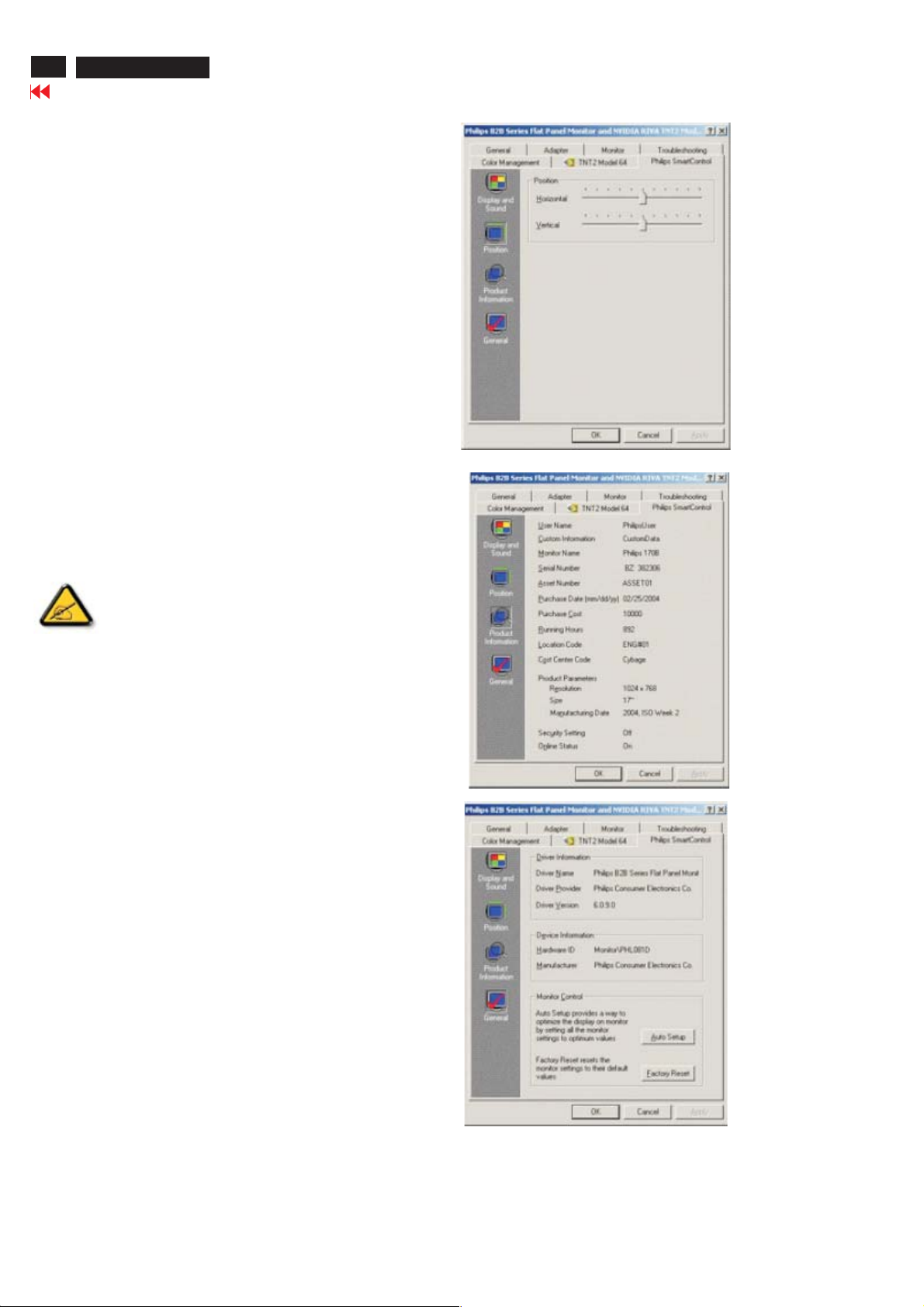
4. SmartControl Options
·
Display and Sound
By moving the sliding bar toward left or right, users will be able to adjust
brightness, contrast,audio volume (if applicable), video noise (not
applicable when using DVI-D input), and color temperatures.(Fig.1)
·
Product Information
Click Product Information in the left pane to view the product information
stored in the monitor's memory.(Fig.2)
·
General
Click on General for general information including driver information
device information, and monitor control.(Fig.3)
Fig.2
Fig.3
Within monitor control, users can click on Auto Setup to achieve
optimum performance or click on factory reset to reset the parameters of
the monitor. Such choices are disabled when using DVI-D (digit) input.

DDC Instructions
190X7&170X7 LCD
Go to cover page
27
General
DDC Data Re-programming
In case the DDC data memory IC or main EEPROM which storage all
factory settings were replaced due to a defect, the serial numbers have
to be re-programmed"Analog DDC IC, & EEPROM".
It is advised to re-soldered DDC IC and main EEPROM from the old
board onto the new board if circuit board have been replaced, in this case
the DDC data does not need to be re-programmed.
Additional information
Additional information about DDC (Display Data Channel) may be
obtained from Video Electronics Standards Association (VESA).
Extended Display Identification Data(EDID) information may be also
obtained from VESA.
System and equipment requirements
1. An i486 (or above) personal computer or compatible.
2. Microsoft operation system Windows 95/98 .
Y o Install the EDID_PORT_Tool under Win2000/XP . As
ou havet
Fig. 1 .
A. Copy the "UserPort.sys" to C:\WINNT\system32\drivers(win2000)
C:\WINDOWS\system32\drivers(winXP)
B. Running " io.exe" everytime, Before you start to programming
edid data .
3. EDID45.exe program .
4. DDC 2BI-ISP TOOL:
Inclusion :
A. DDC2BI-ISP TOOL(3138 106 10396) x1 (as Fig. 2)
B. Printer cable x1
c. (D-Sub) to (D-Sub) cable x2
D. D-SUB to DVI cable X1
Note: The EDID46.EXE is a windows-based program, which cannot
be run in MS-DOS.
To Printer port
Fig. 1Fig. 1
Fig. 2Fig. 2
Pin Assignment
The digital only connector contains 24 signal contacts organized in
three rows of eight contacts. Signal pin assignments are listed in the
following table:
To Printer port
DC 8~12V
DC 8~12V
Power
indicator
Power
Pin No. Description
indicator
Input analog D-sub connector pin assignment
1 T.M.D.S. data22 T.M.D.S. data2+
3 T.M.D.S. data2 shield
4 No Connect
5 No Connect
6 DDC clock
7 DDC data
8 No Connect
9 T.M.D.S. data110 T.M.D.S. data1+
11 T.M.D.S. data1 shield
12 No Connect
13 No Connect
14 +5V Power
15 Ground (for +5V) - Cable detect
16 Hot plug detect
17 T.M.D.S. data018 T.M.D.S. data0+
19 T.M.D.S. data0 shield
20 No Connect
21 No Connect
22 T.M.D.S clock shield
23 T.M.D.S. clock+
24 T.M.D.S. clock-
PIN No. SIGNAL
1Redvideo input
2Greenvideo input / sync on green
3Bluevideo input
4GND
5 GND--Cable detect
6Redvideo GND
7Greenvideo GND
8Bluevideo GND
9 DDC +3.3V or +5V
10 Logic GND
11 GND
12 Serial data line (SDA)
13 H-sync / H+V
14 V-sync
15 Data clock line (SCL)
To Monitor
D-sub/DVI cable
To Monitor
D-sub cable
Fig. 3Fig. 3
Fig. 4Fig. 4
28
190X7&170X7 LCD
Go to cover page
DDC Instructions
Configuration and procedure
There is no Hardware DDC (DDC IC) anymore. Main EEPROM stores
all factory settings and DDC data (EDID code) which is also called
Software DDC. The following section describes the connection and
procedure for Software DDC application. The main EEPROM can be reprogrammed by enabling '' factory memory data write'' function on the
DDC program (EDID46.EXE).
Initialize alignment box
In order to avoid that monitor entering power saving mode due
to sync will cut off by alignment box, it is necessary to initialize
alignment box before running programming software
(EDID46.EXE). Following steps show you the procedures and
connection.
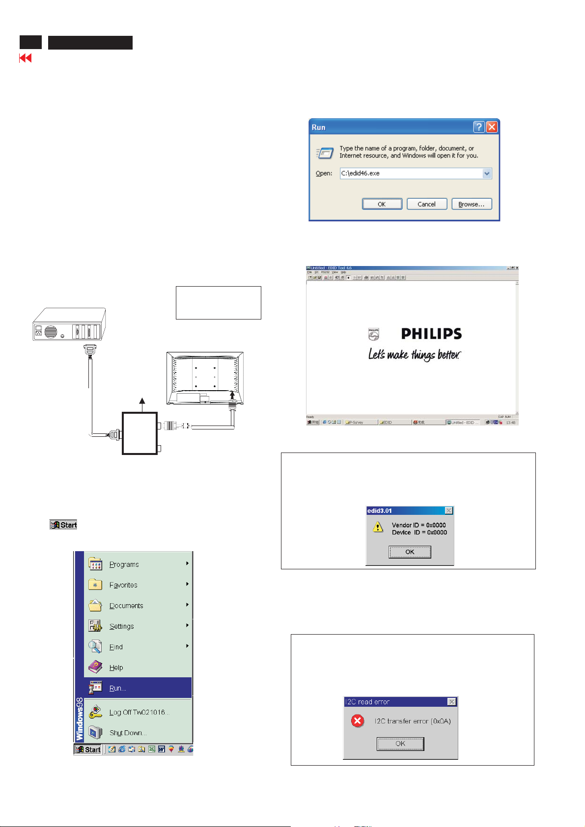
Step 1: Supply 8-12V DC power source to the Alignment box by
plugging a DC power cord .
Step 2: Connecting printer cable and D-Sub cable of monitor as Fig. 4
1=Power connector
PC
2=D-SUB connector
3. At the submenu, type the letter of your computer's hard disk drive
followed by :EDID46 (for example, C:\EDID46, as shown in Fig. 6).
1
Fig. 6
4. Click OK button. The main menu appears (as shown in Fig. 7).
This is for initialize alignment box.
DC Power
8-12 V
Fig. 5
----->
2
----->
To printer port (LTP1)
Step 3: Installation of EDID46.EXE
Method 1: Start on DDC program
Start Microsoft Windows.
1. The Program"EDID46.EXE" in service manual cd-rom be copyed to C:\ .
2. Click , choose Run at start menu of Windows as shown
In Fig. 5.
Printer
Port
To
Monitor
To PC
1
Fig. 4
Fig. 7
Note 1: If the connection is improper, you will see the following error
message (as shown in Fig. 8) before entering the main menu.
Meanwhile, the (read EDID) function will be disable. At this
time, please make sure all cables are connected correctly and
fixedly, and the procedure has been performed properly.
Fig. 8
Note 2: During the loading, EDID46 will verify the EDID data which just
loaded from monitor before proceed any further function, once
the data structure of EDID can not be recognized, the following
error message will appear on the screen as below. Please
confirm following steps to avoid this message.
1. The data structure of EDID was incorrect.
2. DDC IC that you are trying to load data is empty.
3. Wrong communication channel has set at configuration setup
windows.
4. Cables loosed or poor contact of connection.
Fig. 9
DDC Instructions
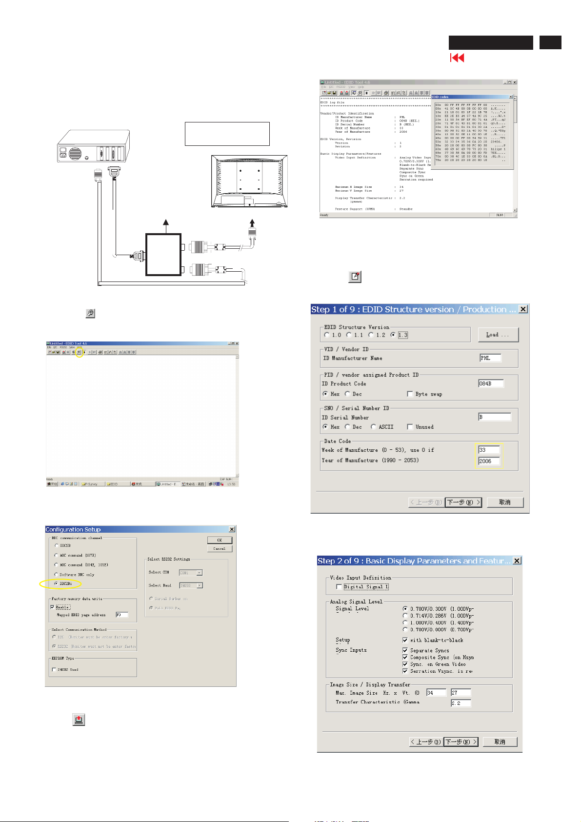
Re-programming Analog DDC IC
Step 1: After initialize alignment box, connecting all
cables and box as shown in Fig. 10.
PC
1=Power connector
2=D-SUB conne ctor
190X6&170X6 LCD
Gotocover page
29
TP1)
DC Power
8-12V
To printer port (L
To PC Video port (D-sub)
Printer
Port
To
Monitor
To P C
1
2
----->
----->
Fig.10
Step 2: Read DDC data from monitor
1. Click icon as shown in Fig. 11 from the tool bar to bring up
the Channels "Configuration Setup" windows as shown in Fig.11.
=====>
Click this button
Fig.11
Fig.13
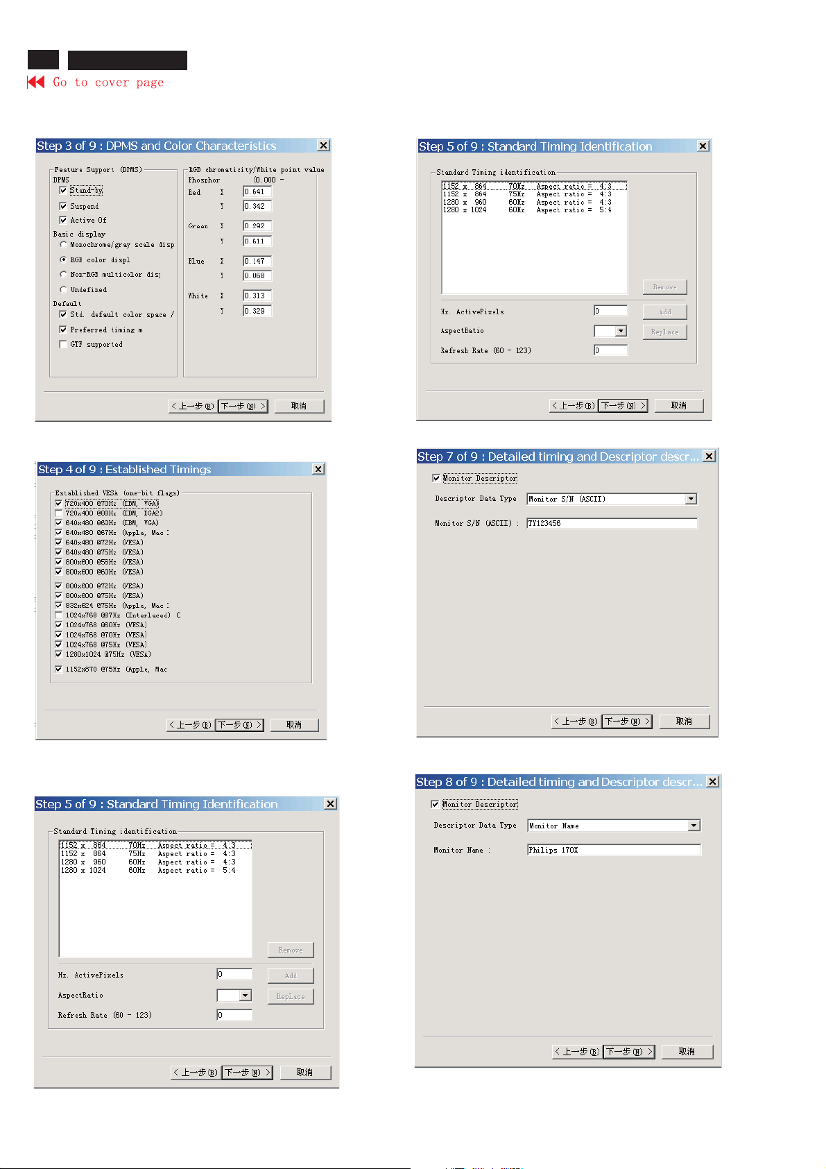
Step 3: Modify DDC data (verify EDID version, week,
year)
Click (new function) icon from the tool bar, bring up
Step 1of9as shown in Fig.14.
EDID46 DDC application providesthe function selection and
2. Select the DDC2Bi asthe communication channel.
As shown in Fig. 12.
Fig.12
3. Click OK button to confirm your selection.
4. Click icon (Read EDID function) to read DDC EDID data from
monitor. The EDID codes will displayonscreen as shown in Fig. 13.
Select and fill out,
If necessary.
Step 4: Modify DDC data (Monitor Serial No.)
1. Click Next , bring up Fig. 15.
Fig.14
Fig.15
30
190X6&170X6 LCD
DDC Instructions
2. Click Next , bring up Fig.16.
3. Click Next , bring up Fig.17.
5. Click Next , bring up Fig.19.
Fig. 19
Fig. 16
6. Click Next , bring up Fig. 20.
4. Click Next , bring up Fig.18.
Fig. 17
Fig. 18
Fig. 20
7. Click Next , bring up Fig. 21.
Fig. 21
 Loading...