

Philips 170X6FB/00, 170X6FB/93, 170X6FW/93, 190X6FB/00, 190X6/FB/93 Service Manual
...
Service
Service
Service
Published by BCU Monitors Printed in suzhou Copyright reserved Subject to modification F Jul .4 2005
Description Page
Important Safety Notice------------------------------- 2
Technical Data/Installation------------------------3~6
On-Screen Display/Aging Mode--------------------7~9
Mechanical instructions--------------------------12~13
Warning Message--------------------------------17~18
Factory Mode/Pixel defect policy---------------10~11
Display adjustment/Trouble shooting----------14~16
Electrical Instructions---------------------------19~22
LightFrameDR------------------------------------23~24
DDC Instructions/DATA--------------------------25~33
ISP Instructions----------------------------------34~36
Wiring Diagram-----------------------------------37~38
Block Diagram----------------------------------------39
Description Page
Scaler Diagram/C.B.A---------------------------40~46
Audio Diagram/C.B.A---------------------------47~54
Power Diagram/C.B.A---------------------------55~57
USB Diagram/C.B.A-----------------------------58~60
Control&Earphone Diagram/C.B.A-------------61~63
Exploded View---------------------------------- 64~65
Recommended Parts list-----------------------------66
Spare Parts list-----------------------------------67~71
Repair Tips/Repair Flow Chart-----------------72~76
General product specification----------------77~102
Different parts list---------------------------------103
Safety Test Requirements--------------------------104
REFER TO BACK COVER FOR IMPORTANT SAFETY GUIDELINES
CAUTION: USE A SEPARATE ISOLATION TRANSFORMER FOR THIS UNIT WHEN SERVICING.
ANY PERSON ATTEMPTING TO SERVICE THIS CHASSIS MUST FAMILIARIZE HIMSELF WITH THE CHASSIS
AND BE AWARE OF THE NECESSARY SAFETY PRECAUTIONS TO BE USED WHEN SERVICING ELECTRONIC
EQUIPMENT CONTAINING HIGH VOLTAGES.
GB
3138 106 10478
170X6FB/00
170X6FB/93
170X6FW/00
170X6FW/93
190X6FB/00
190X6/FB/93
Important Safety Notice
2
FOR PRODUCTS CONTAINING LASER :
Invisible laser radiation when open.
AVOID DIRECT EXPOSURE TO BEAM.
Use of controls or adjustments or
performance of procedures other than
those specified herein may result in
hazardous radiation exposure.
The use of optical instruments with this
product will increase eye hazard.
DANGER-
CAUTION-
CAUTION-
TO ENSURE THE CONTINUED RELIABILITY OF THIS
PRODUCT, USE ONLY ORIGINAL MANUFACTURER'S
REPLACEMENT PARTS, WHICH ARE LISTED WITH
THEIR PART NUMBERS IN THE PARTS LIST SECTION
OF THIS SERVICE MANUAL.
190X6&170X6 LCD
Proper service and repair is important to the safe,
reliable operation of all Philips Consumer Electronics
Company** Equipment. The service procedures
recommended by Philips and described in this service
manual are effective methods of performing service
operations. Some of these service operations require
theuseoftoolsspeciallydesignedforthepurpose.The
specialtoolsshouldbeusedwhenandas
recommended.
Itisimportanttonotethatthismanualcontains
various CAUTIONS and NOTICES which should be
carefully read in order to minimize the risk of personal
injury to service personnel. The possibility exists that
improper service methods may damage the equipment.
It is also important to understand that these
CAUTIONS and NOTICES ARE NOT EXHAUSTIVE.
Philips could not possibly know, evaluate and advise
theservicetradeofallconceivablewaysinwhich
service might be done or of the possible hazardous
consequences of each way. Consequently, Philips has
not undertaken any such broad evaluation. Accordingly,
aservicerwhousesaserviceprocedureortoolwhich
is not recommended by Philips must first satisfy
himself thoroughly that neither his safety nor the safe
operationoftheequipmentwillbejeopardizedbythe
service method selected.
* *Hereafter throughout this manual, Philips Consumer
Electronics Company will be referred to as Philips.
WARNING
Critical components having special safety
characteristics are identified with a by the Ref. No.
in the parts list and enclosed within a broken line*
(where several critical components are grouped in one
area)alongwiththesafetysymbol onthe
schematics or exploded views.
Use of substitute replacement parts which do not have
the same specified safety characteristics may create
shock, fire, or other hazards.
Under no circumstances should the original design be
modified or altered without written permission from
Philips. Philips assumes no liability, express or implied,
arising out of any unauthorized modification of design.
Servicer assumes all liability.
*BrokenLine
Take care during handling the LCD module with
Backlight unit
- Must mount the module using mounting holes
arranged in four corners.
-Donotpressonthepanel,edgeoftheframe
stronglyorelectricshockasthiswillresultin
damage to the screen.
-Donotscratchorpressonthepanelwithanysharp
objects,suchaspencilorpenasthismayresultin
damage to the panel.
- Protect the module from the ESD as it may damage
the electronic circuit (C-MOS).
- Make certain that treatment person s body are
grounded through wrist band.
-Donotleavethemoduleinhightemperatureandin
areasofhighhumidityforalongtime.
-Avoidcontactwithwaterasitmayashortcircuit
within the module.
- If the surface of panel become dirty, please wipe it
offwithasoftmaterial.(Cleaningwithadirtyor
rough cloth may damage the panel.)
Go to cover page
3
1. General
1.1 Product description
190X6 is the 6th generation of Hudson 19 TFT Flat Panel Display
Monitor. The monitor featured with both DVI-D and analog signal
Input interface, and modularized as a display unit with embedded
Universal AC power supplies inside monitor main body. The power
Button and display control buttons (tact switch type) are on the front
And the right-hand side of the monitor. The monitor shall support an
Internal scaler to automatically enable the monitor to display lower
Resolution video modes into 1280 x 1024 full screen display. The
Image can be adjusted through OSD control board. These adjustments
Can be stored on a board memory including 34 pre-set modes and 16
factory pre-set modes.
1.1.2 Destination: AP, CN, EE, GB, LA, ME, SH, WE
1.2. Basic data
1.2.1 LCD panel
Type NR. : LM190E03-TLB2/TLB4 (LPL)
Number of Pixels. : 1280 (H) x1024 (V)
Physical Size. : 396.0(w)*324.0(h)*16.5(d) mm
Pixel Pitch. : 0.098 (per one triad) x 0.294 mm
Color pixel arrangement : RGB vertical stripes
Support Color. : 16.2M colors (RGB 8 bits data)
Display Mode. : Normally White
Backlight. : CCFL edge light system
Active area. (WXH). : 376.32 x 301.056mm (19 diagonal)
Viewing Angle. : Vertical 140 degree, Horizontal 140 degree (CR=10)
Contrast ratio. : 700:1
White luminance. : 300nits (Typ)
190X6&170X6 LCD
Go to cover page
Technical Data(For 190X6)
"
"
"
"
1.2.2. Power supply
Main Voltage: AC 90 - 135 Vrms and 170 - 264 Vrms, 50/60±2Hz
Power consumption: 40 watts max (full loading, with audio)
Operating < 32W(typical value, without audio)
Standby < 1W.
DC power switch off < 1W (Excluded audio load)
Power cord length: 1.5M
Power cord type: 3 lead with earth plug
Power indicator: LED (ON: green, Standby: amber)
Auto power saving: EPA, Nutek, VESA, DPMS,
STATUS
HsyncV-sync
Video Power LED
On On On Active <40W
Green /With
Audio
On On On Active <32W
Green / Without
Audio
Off Off Off Blanked <1W Amber LED
DC
Power
off
N / A <1W LED Off
Note :
To achieve under 1 Watt power saving when Stand-Alone Audio
feature is selected On and system is in Sleep Mode, follow below
condition :Volume has to be adjusted to 0% prior to measurement.
1.2.3. Horizontal scan: 30 - 83 KHz
1.2.4. Vertical scan: 56 - 76 Hz
1.2.5. Input signals
The input signals can be applied in two different modes:
1). VESA Analog
The video input consists of red, green, and blue signals. The video
Signals are analog levels, where 0V corresponds to black and 700mV
is the maximum signal amplitude. Input impedance of video pins is
75 ohm +/- 1%.
The capability of sync signal inputs shall include separate sync,
composite sync and sync on green. input impedance: 2k2 ohms
The signals are defined as follow:
Separate sync TTL level, Positive/Negative
Composite sync TTL level, Positive/Negative
Sync on green H-sync TTL level, Positive/Negative
2). Intel DVI Digital
Input signal: Four channel TMDS signals
Signal source: pattern generator format as the SPEC
1.2.6 Audio
Input signal level: 500mVrms
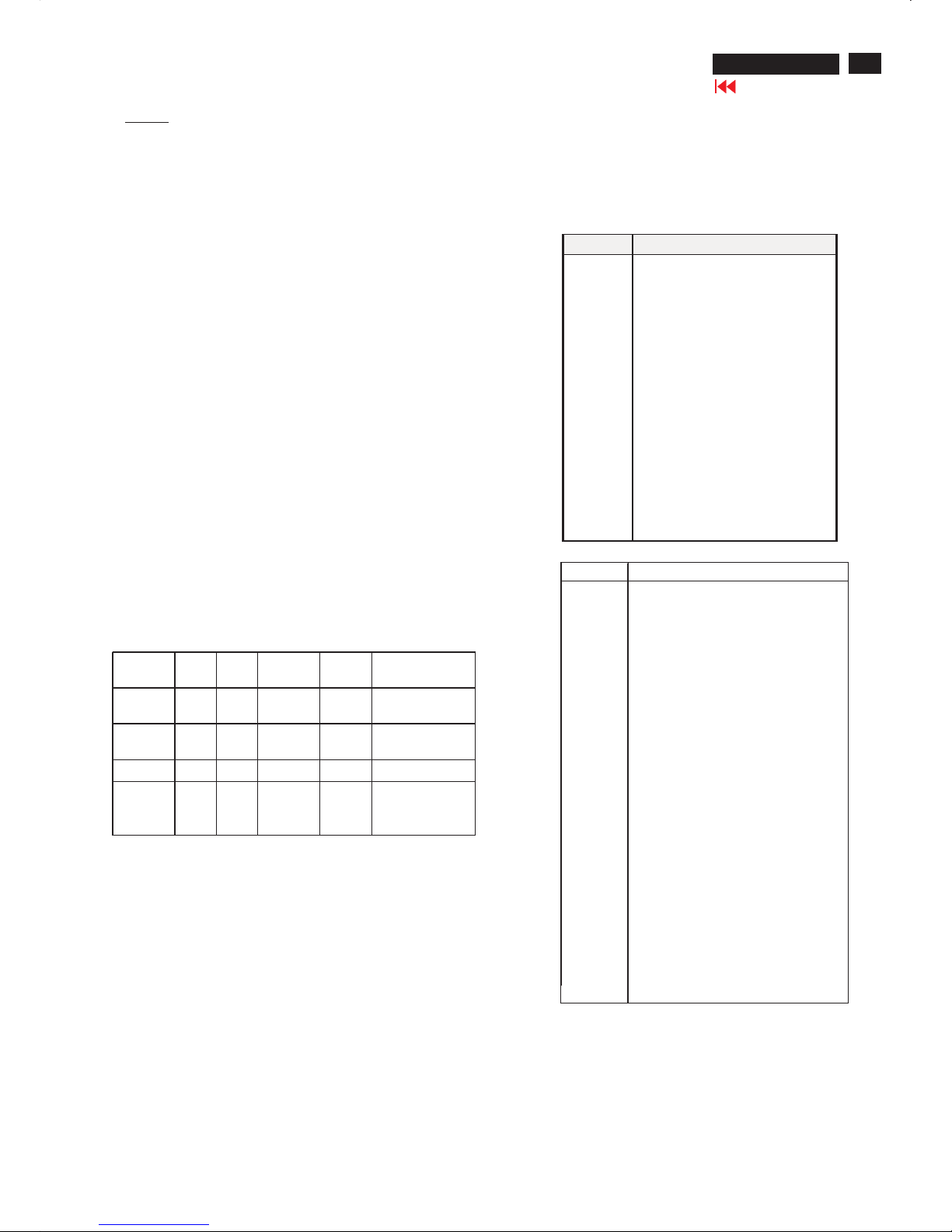
1.2.7 Input connectors
(1) Input analog D-sub connector pin assignment
(2) Input DVI-D connector pin assignment
Pin No. Description
1 T.M.D.S. data22 T.M.D.S. data2+
3 T.M.D.S. data2 shield
4 No Connect
5 No Connect
6 DDC clock
7 DDC data
8 No Connect
9 T.M.D.S. data110 T.M.D.S. data1+
11 T.M.D.S. data1 shield
12 No Connect
13 No Connect
14 +5V Power
15 Ground (for +5V) - Cable detect
16 Hot plug detect
17 T.M.D.S. data018 T.M.D.S. data0+
19 T.M.D.S. data0 shield
20 No Connect
21 No Connect
22 T.M.D.S clock shield
23 T.M.D.S. clock+
24 T.M.D.S. clock-
Signal interface 15Pins, D-sub male with DDC-2B Pin
assignments
24Pins, DVI-D male with DDC-2B Pin assignments
PIN No. SIGNAL
1 Red video input
2 Green video input / sync on green
3 Blue video input
4GND
5 GND -Cable detect
6 Red video GND
7 Green video GND
8 Blue video GND
9 DDC +3.3V or +5V
10 Logic GND
11 GND
12 Serial data line (SDA)
13 H-sync / H+V
14 V-sync
15 Data clock line (SCL)
4
190X6&170X6 LCD
Go to cover page
Technical Data(For 170X6)
1.General
1.1 Product descrip tion
170X6 is the 6th generation of Hudson 17 TFT Flat Panel Display
Monitor. The monitor featuredwith both DVI-Dand analogsignal
input interface, andmodularized as a displayunit with embedded
universal AC power supplies inside monitor main bo
dy. The power
button anddisplay control buttons (tact switch type) are on the front
and the right-handsideof the monitor. The monitor shall support an
internal scaler to automatically enable the monitor to display lower
resolution video modes into 1280 x 1024 full screen display. The
imag
ecanbeadjusted through OSD control board. These
adjustments can be stored on a boardmemory including34pre-set
modes and 16 factorypre-set modes.
1.1.1Destination: AP, CN, EE, GB, LA, ME, SH, WE
1.2. Basic data
1.2.1 LCD panel
Type NR. : LM170E01-TLA5/TLA8 (LPL)
Numb
er ofPixels. : 1280(H) x1024 (V)
Physical Size. : 358.5(w)*296.5(h)*17.0(d) mm
Pixel Pitch.:0.264 (per one triad) x 0.264mm
Color pixel arrangement.:RGBvertical stripes
Support Color.:16.2M colors (RGB 8 bitsdata)
DisplayMode.:N
ormallyWhite
Backlight.:CCFL edgelight system
Activearea. (WXH).:337.92 x 270.336mm (17 diagonal)
ViewingAngle.:Vertical 140 degree,Horizontal 140 degree (CR=10)
Contrastratio.:600:1(Typ)
White luminance.:250nits (Typ)
1.2.2. Power supply
M
ain Voltage:AC90 - 135 Vrms and 170 -264Vrms, 50/60±2Hz
Power consumption:38wattsmax
Operating < 35W(typical value)
Standby<1W.
DCpower switch off < 1W (Exclusiveof audio load)
Power cord length: 1.8M
Power cord type:3leadwith earth plug
P
ower indicator:LED(ON: green,Standby: amber)
Auto power saving: EPA, Nutek, VESA, DPMS,
STATUS
HsyncV-sync
Video Power LED
On On On Active <38W
Green /With
Audio
On On On Active <32W
Green /
Without Audio
Off Off Off Blanked<1WAmber LED
DCPower
off
N/A <1WLED Off
Note :
To achieve under 1 Watt power savingwhen Stand-Alone Audio
feature isselectedOnand system is in SleepMode,followbelow
condition :
Volumehas to beadjusted to 0%prior to measurement.
1.2.3. Horizontal scan:30 -83KHz
1.2.4. Vertical scan:56 - 76 Hz
1.2.5. In
put signals
The input signals can beapplied in two different modes:
1). VESA Analog
The video inputconsists of red, green, andblue signals. The video
Signals are analog levels, where 0V corresponds to black and 700mV
is the max
imum signal amplitude.Inputimpedance ofvideo pins is
75 ohm+/-1%.The capability ofsync signal inputsshall include separate
sync, composite sync andsync on green. inputimpedance:2k2ohms
The signals are defined asfollow:
Separate sy
nc TTL level,Positive/Negative
Composite sync TTL level,Positive/Negative
Sync on green H-sync TTL level,Positive/Negative
""
"
"
""
2).Intel DVI Digital Input signal: Four channel TMDSsignals
Signal source:pattern generator format as the spec
1.2.6 Audio Amplifier and headphone section :
Output power:2x2Wrms into 16 Ohm
Input sensitivity: 500mVrms Frequency range:
100Hz - 20KHz
Volume control keypads are at the front control panel.
L/R input via 1.8m hard-wired cable with lime green 3.5mm plug
Headphone connection will mute speakers.
Loudspeaker section :
Rated input 2.0WMax. input 3.0W
Impedance 16 Ohm+/- 15%
Sensitivity 76 dB +/-3 dB (at 1W/
1m at 1KHz)
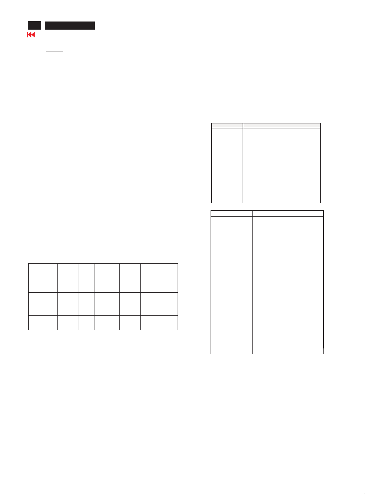
1.2.7 Input connectors
(1) Input analog D-sub connector pin assignment
(2) InputDVI-D connector pin assignment
Pin No. Description
1T.M.D.S. data2-
2 T.M.D.S. data2+
3 T.M.D.S. data2shield
4No Connect
5No Connect
6DDC clock
7DDCdata
8No Connect
9 T.M.D.S. data1-
10 T.M.D.S. data1+
11 T.M.D.S. data1 shield
12No Connect
13No Connect
14+5VPower
15Ground (for +5V) -Cable
detect
16 Hot plug detect
17 T.M.D.S. data018 T.M.D.S. data0+
19 T.M.D.S. data0 shield
20 No Connect
21 No Connect
22 T.M.D.S clockshield
23 T.M.D.S. clock+
24 T.M.D.S. clock-
Signal interface
15Pins, D-sub male with DDC-2B Pin assignments
24Pins, DVI-D male with DDC-2B Pin assignments
Sync polarity: H-sync positive/negative
V-sync positive/negative
PIN No. SIGNAL
1 Redvideo input
2Green video input /sync on green
3Blue video input
4GND
5GND -Cable detect
6 Redvideo GND
7 Green video GND
8Blue video GND
9 DDC +3.3V or +5V
10 Logic GND
11 GND
12Serial data line (SDA)
13 H-sync /H+V
14V-sync
15 Data clock line (SCL)
5
190X6&170X6 LCD
Go to cover page
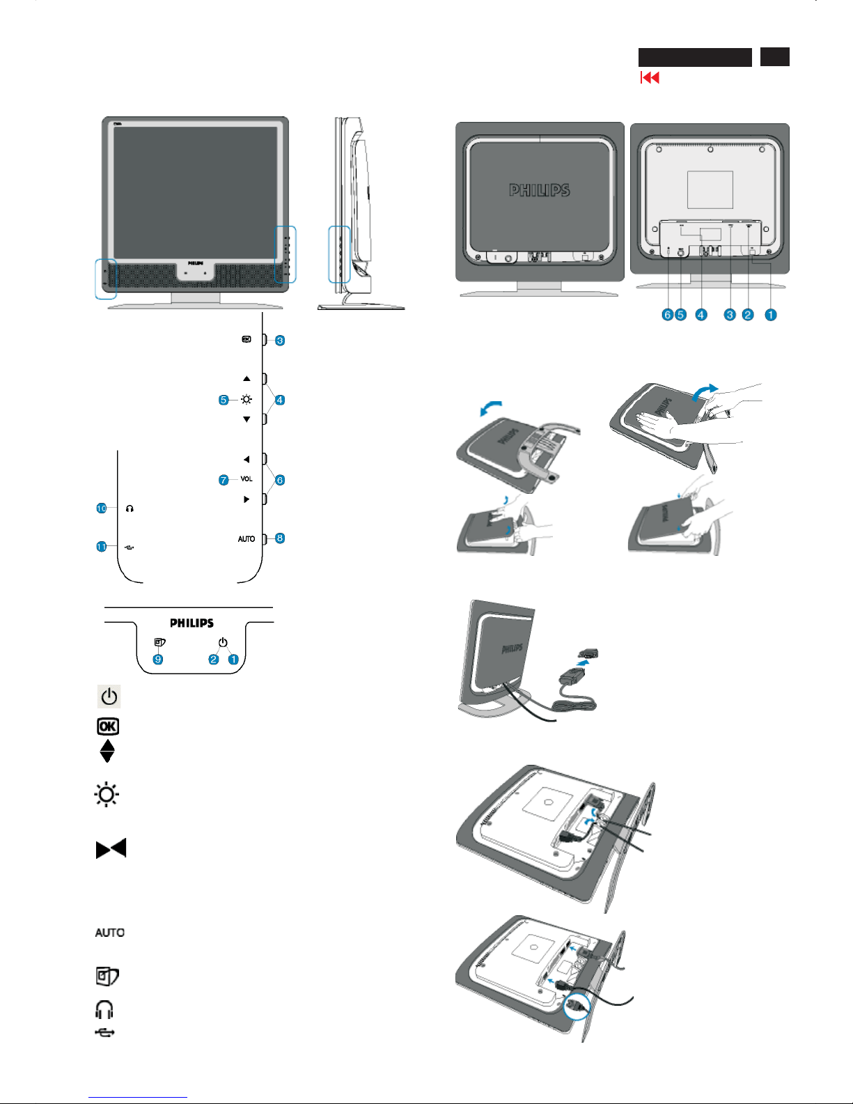
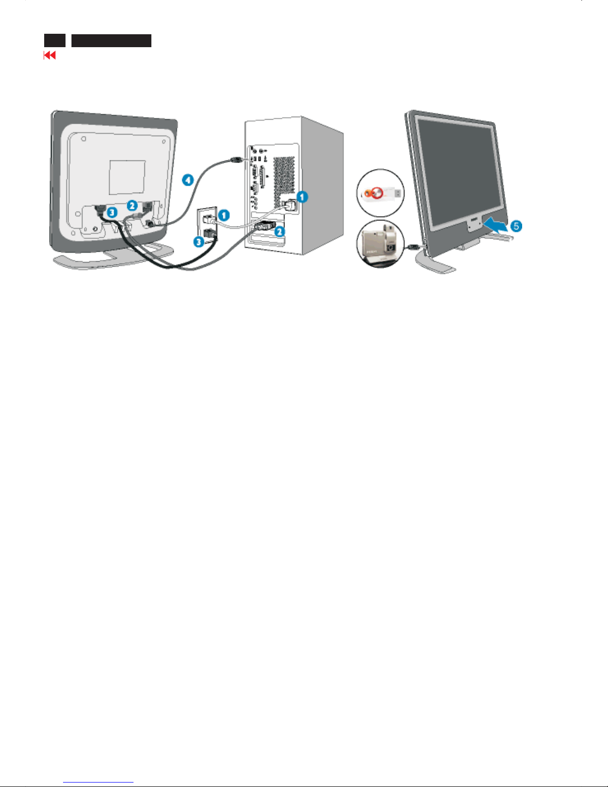
Connection to PC
Front view
Power button switchesyour monitor on.
Power LED
OK button which when pressed will take you to the OSD controls
UPandDOWNbuttons are used when adjusting the OSD ofyour
monitor.
BRIGHTNESS hotkey. When the UPandDOWNarrow
buttons are pressed, theadjustment controls for the BRIGHTNESS
will show up.
LEFT andRIGHT buttons, likethe UPandDOWNbuttons, are
also used in adjusting the OSD ofyour monitor.
VOLUME hotkey. When the LEFT andRIGHT arrow buttons are
pressed, theadjustment controls for VOLUME will show up.
Automatically adjustthe horizontal
position, vertical position,
phaseand clocksetting.
LightFrame
TM
hotkey to select full-screen modes among
Internet, Photo andVideo-TV.
Earphone jack(on side).
USB port for versatile peripheral connections
VOLUME
Rear View
1.USB upstream port
2.VGA input
3.DVI-D input
4.AC power input
5.PC audio input
6.Kensington anti-thieflock
Connecting to yourPC
If youuseanApple Macintosh, you need to connect the specialMac
adapter to one end of the monitor signal cable.
Cable management
6
190X6&170X6 LCD
Go to cover page
Connection to PC
Connect to PC
1. Turnoff your computerandunplug itspower cable.
2. Connect the monitorsignal cabletothe video connector on the back ofyour computer
3. Plug the power cord ofyour computerandyour monitor into a nearby outlet
4. USB plug
(a) Connect USB upstre
am portonmonitorand the USB portonPCwithaUSBcable.
(b) The USB downstream portis nowready foranyUSBdevice to plug in
5. Turnonyour computerandmonitor. If the monitordisplays animage, installation is complete.
Note: The USB plug is a pass through connection wh
ether it can support USB 1.1 orUSB2.0depends on your PC's
specification.
7
190X6&170X6 LCD
Go to cover page
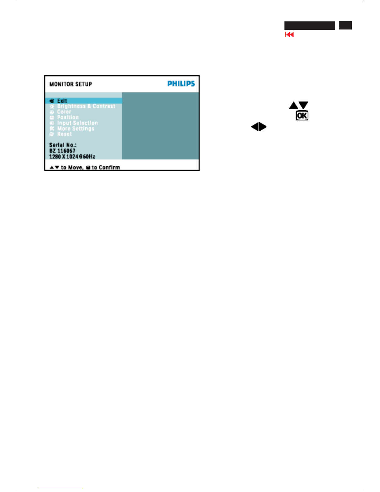
On Screen Display
On-Screen Display (OSD) is a feature in all Philips LCD monitors.It allowsanenduser to adjust screen performance
or select functions of the monitors directly through an on-screen instruction window. A user friendly on screen display
interface is shownasbelow:
Basic and simple instruction on the control keys.
IntheOSDshownabove users can press
buttons at the
front bezel of the monitor to move thecursor,
to confirm the
choice or change, and
to adjust/select thechange
Note: sRGB is a standardfor ensuring correct exchange of colors between different devices (e.g.digital cameras,
monitors, printers, scanners, etc.)
Usingastandardunified color space, sRGBwill help represent pictures taken byansRGB compatible device correctly
on yoursRGB enabledPhilips monitors.Inthat way
, the colors are calibrated and you can rely on the correctness of
thecolorsshownonyour screen.
Important with the use of sRGB is that the brightness and contrast of your monitor is fixed toapredefined setting as
well as the color gamut.Therefore it is important to select thesRGB setting in the monitor'sOSD.
To doso, open th
eOSDbypressingtheOKbuttononthesideof your monitor.Move the down buttontogotoColor
and press OK again.Use theright buttontogotosRGB. Then move the down button and press OK again to exit the
OSD.
After this, please do not change the brightness or contrast setting of your monitor.Ifyou change either of these,
the
monitor will exit thesRGBmodeand go to a color temperature setting of 6500K.
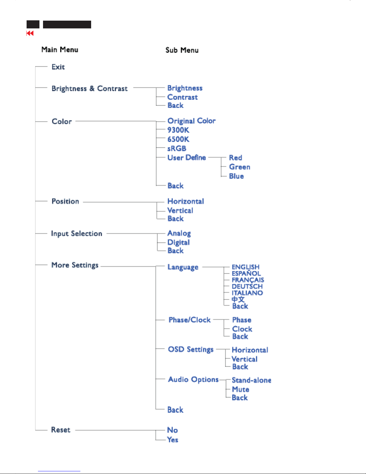
TheOSDTree(page8)
Below is an overall view of thestructure of theOn-Screen Display.You can use this as a reference when youwant to
work your way around the different adjustments later on.
8
190X6&170X6 LCD
Go to cover page
On Screen Display
9
190X6&170X6 LCD
Go to cover page
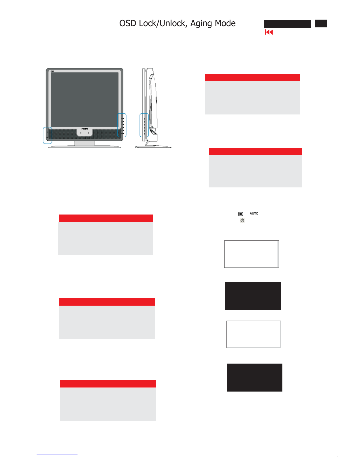
Front Control Panel
To Lock/Unlock OSD FUNCTION(User Mode)
The OSD function can be locked by pressing"OK"button(1) for more
than 10 seconds, the screen shows following windows for 3 seconds.
Everytime when you press"AUTO" or "OK" button, this message appears on the screen automatically.
ATTENTION SIGNAL
OSD MAIN CONTROLS UNLOCKED
Unlock OSD function
Locked OSD function can be released by pressing "OK" button for more
than 10 seconds again
ATTENTION SIGNAL
OSD MAIN CONTROLS LOCKED
NO VIDEO INPUT
This screen appears if there is no video signal input. Please check that
the signal is properly connected to the video card of PC and make sure
PC is on
ATTENTION SIGNAL
CHECK CABLE CONNECTION
CANNOT DISPLAY THIS VIDEO MODE..
This screen warns when the input frequency from the computer is not
a standard video mode or out of the monitor's scanning range.
Please change the display mode of the operating software in the computer(i.e.windows) to 1280*1024@60HZ for best display results.
ATTENTION SIGNAL
CANNOT DISPLAY THIS VIDEO
MODE,CHANGE COMPUTER DISPLAY
INPUT TO 1280*1024@60HZ
I
WAIT FOR AUTOMATIC ADJUSTMENT
This screen appears when you press the "AUTO" buttons at the same
time. It will disappear when the monitor is properly adjusted
ATTENTION SIGNAL
WAITING FOR AUTOMATIC ADJUSTMENT
Access Aging.. Mode
Step1:TurnoffLCDmonitor, and disconnect Interface Cable
between Monitor and PC.
Step 2 : [Push AUTO " " & " " buttons at the same time and
hold it]+[Press power " " button until comes out " AGING screen"
] => then release all buttons.
Bring up:
AGING...
After 15 seconds, bring up:
After 15 seconds, bring up:
AGING...
After 15 seconds, bring up:
----------
---------repeatly
Connect Signal cable again=> go back to normal display
10
190X6&170X6 LCD
Go to cover page
Front Control Panel
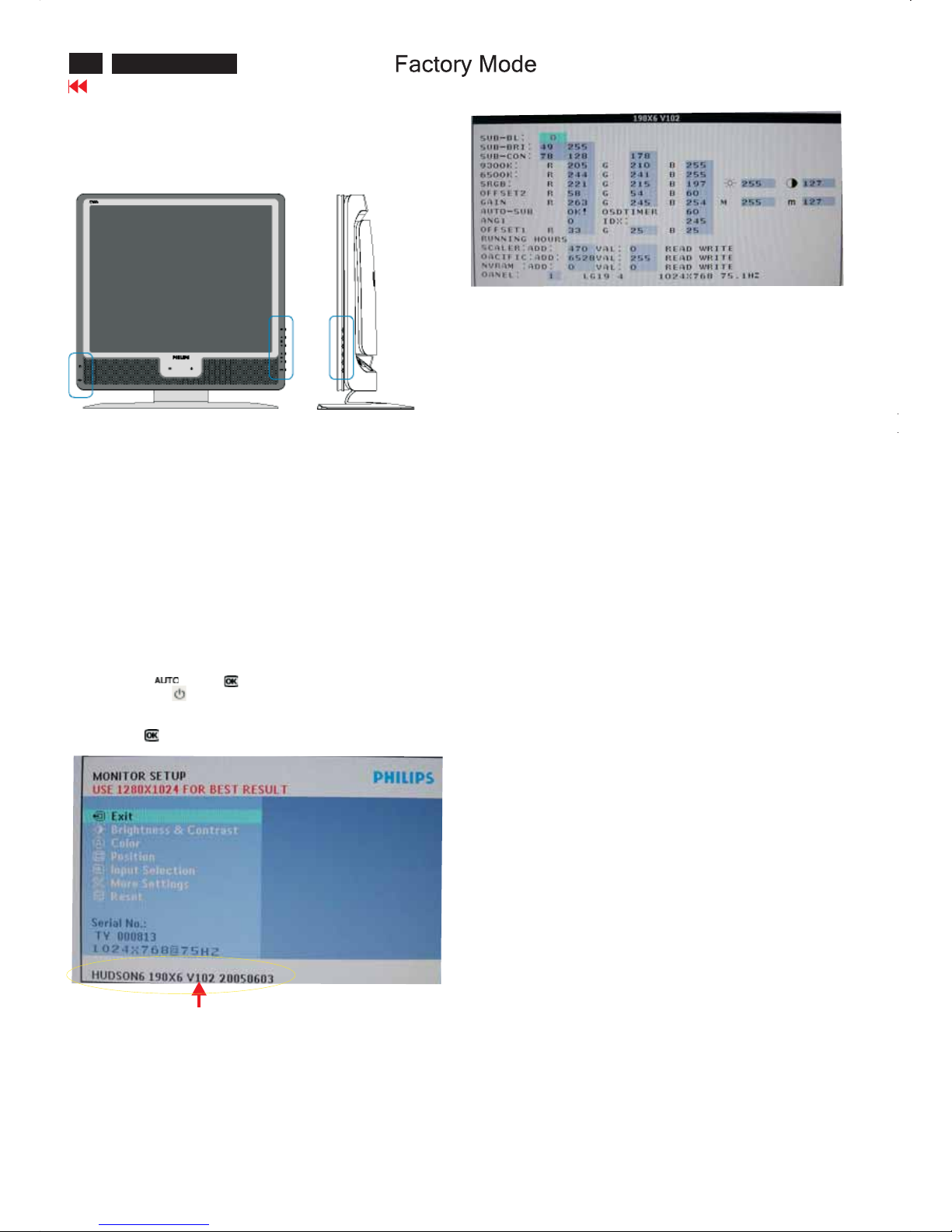
Access Factory Mode
How to get into Factory Mode Menu
Step1:
Turn off monitor.
Step2:
[Push AUTO " " & OK " " buttons at the same time and hold it]
+[Press power " " button untill comes out "Windows screen" ]
=> then release all buttons
Step3:
Press OK " " button, bring up Factory mode indication as shown
in Fig2.
Factory Mode indicator
Factory Menu
Cursor can move on gray color area
Hot key function: by pressing " up " and " DOWN " key
Simultaneously at User Mode (or Factory Mode)
(PS: The OffsetRGBfunction can be used on reduce or eliminate
snowy noise on the background when the resolution of video signal
is 1280*1024 vertical 60Hz. Slightly increase or decrease the value
until snowy noise completely disappear
BL : Blacklevel value
SUB-BRI : Brightness value range (Min Max)
SUB-CON : Contrast value range (Min Mid Max)
SRGB-B : Brightness of sRGB
SRGB-C : Contrast of sRGB
Gain-m : Minimum value of User Gain
Gain-M:Maximum value of User Gain
AUTO-SUB: To do Auto color function when push Menu key in white
pattern
OSDTIMER : OSD time out control (sec)
ANG1 : For analog only project control (0:Dual, 1:Analog only)
IDX : Limit current of inverter, 170X6: 200, 190X6: 245
SCALER : Read/Write scaler register
NVRAM : Read/Write eeprom address
Panel : LG(LG.Philips panel)
11
190X6&170X6 LCD
Go to cover page
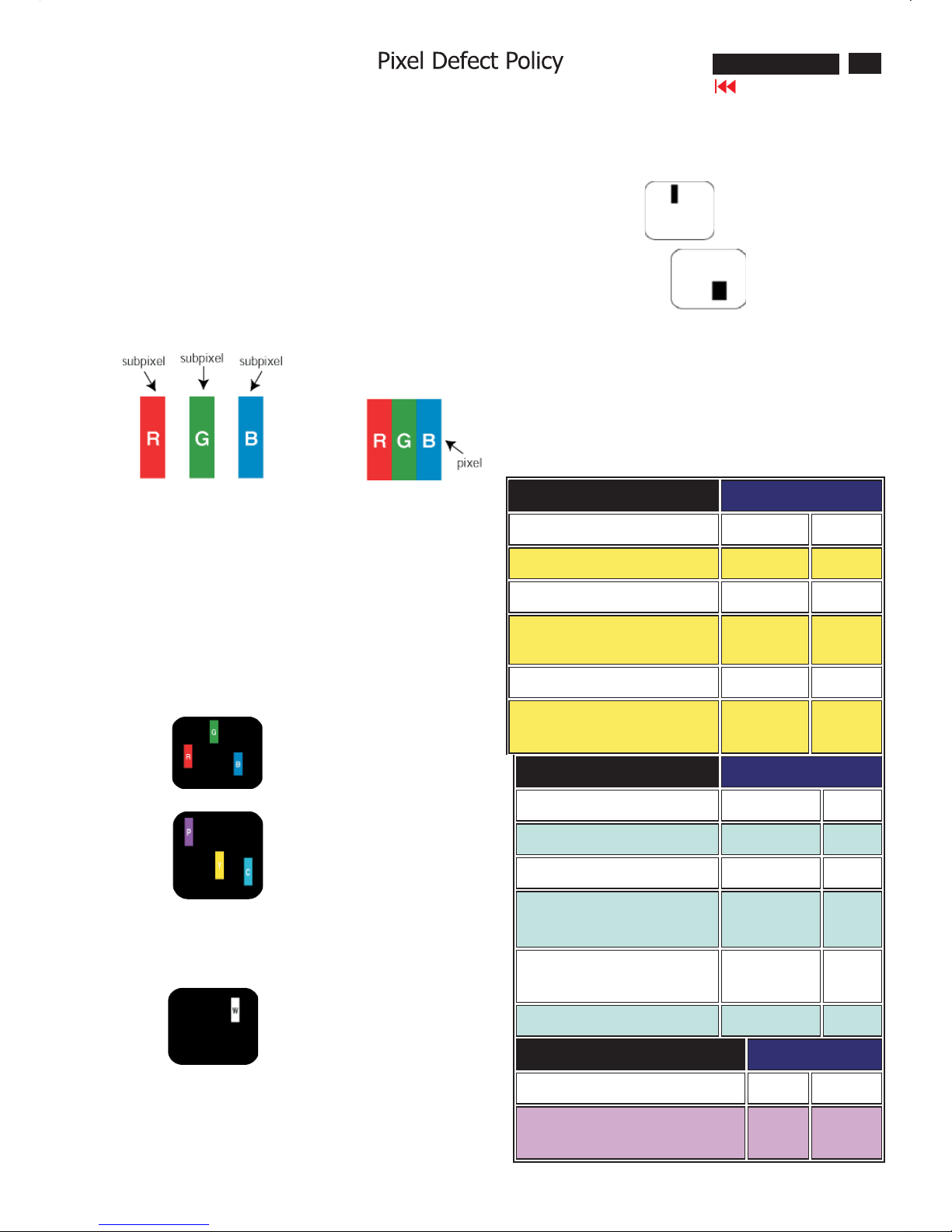
Philips' Flat Panel Monitors Pixel Defect Policy
Pixels and Subpixels
Types of Pixel Defects
Philips strives to deliver the highest quality products. We use some of
the industry's most advanced manufacturing processes and practice
stringent quality control. However, pixel or subpixel defects on the TFT
LCD panels used in flat panel monitors are sometimes unavoidable.
No manufacturer can guarantee that all panels will be free from pixel
defects, but Philips guarantees that any monitor with an unacceptable
number of defects will be repaired or replaced under warranty.
This notice explains the different types of pixel defects and defines
acceptable defect levels for each type. In order to qualify for repair or
replacement under warranty, the number of pixel defects on a TFT LCD
panel must exceed these acceptable levels.
For example, no more than 0.0004% of the subpixels on a 15" XGA
monitor may be defective. Furthermore, Philips sets even higher quality
standards for certain types or combinations of pixel defects that are
more noticeable than others. This policy is valid worldwide .
A pixel, or picture element, is composed of three subpixels in the
primary colors of red, green and blue. Many pixels together form an
image. When all subpixels of a pixel are lit, the three colored subpixels
together appear as a single white pixel. When all are dark, the three
colored subpixels together appear as a single black pixel.
Other combinations of lit and dark subpixels appear as single pixels of
other colors.
Pixel and subpixel defects appear on the screen in different ways.
There are two categories of pixel defects and several types of subpixel
defects within each category.
Bright Dot Defects Bright dot defects appear as pixels or subpixels that
are always lit or "on".
These are the types of bright dot defects:
One lit red, green or blue subpixel
Two adjacent lit subpixels:
- Red + Blue = Purple
-Red+Green=Yellow
- Green + Blue = Cyan (Light Blue)
Three adjacent lit subpixels
(one white pixel)
Black Dot Defects
Proximity of Pixel Defects
Pixel Defect Tolerances
Black dot defects appear as pixels or subpixels that are always dark or
"off".
These are the types of black dot defects:
One dark subpixel
Two or three adjacent dark subpixels
Because pixel and subpixels defects of the same type that are nearby
one another may be more noticeable, Philips also specifies tolerances
for the proximity of pixel defects.
In order to qualify for repair or replacement due to pixel defects during
the warranty period, a TFT LCD panel in a Philips flat panel monitor
must have pixel or subpixel defects exceeding the tolerances listed in
the following tables.
BRIGHT DOT DEFECTS ACCEPTABLE LEVEL
MODEL
170X6 190X6
1 lit subpixel 0 0
2 adjacent lit subpixels 0 0
3 adjacent lit subpixels (one white pixel) 0 0
Distance between two bright dot defects* 00
Total bright dot defects of all types 0 0
BLACK DOT DEFECTS ACCEPTABLE LEVEL
MODEL
170X6 190X6
1 dark subpixel 0 0
2 adjacent dark subpixels 0 0
3 adjacent dark subpixels 0 0
Distance between two black dot
defects*
00
Total black dot defects of all types 0 0
TOTAL DOT DEFECTS ACCEPTABLE LEVEL
MODEL
170X6 190X6
Total bright or black dot defects
of all types
0 0
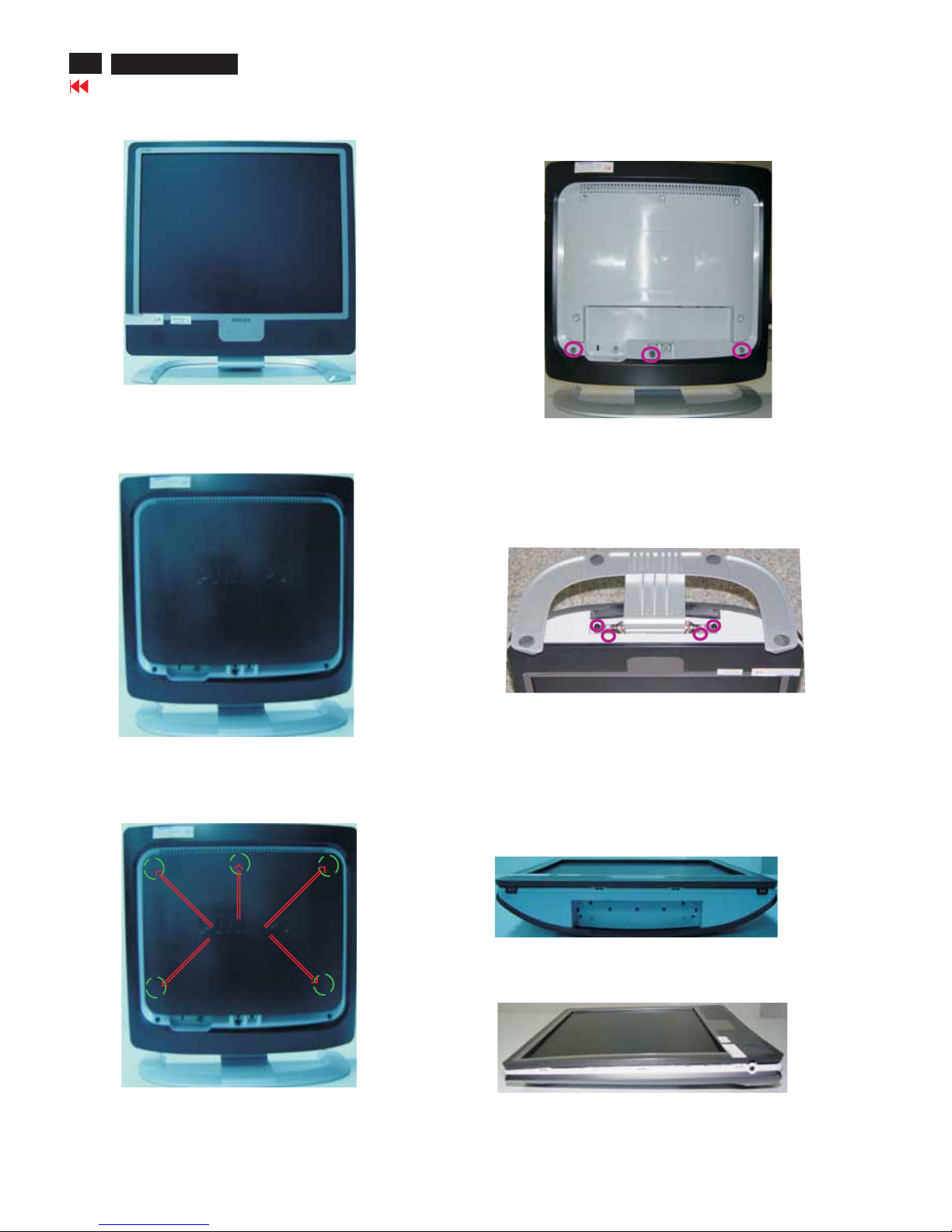
Mechanical Instructions
Fig. 3
Clip
Front View
Back View
Step 3:
-Unscrew the four screws as shown in Fig. 5.
- Remove the base.
Fig. 1
Step 4: Remove the front bezel
- Use thin "l" type screwdriver to open 4 clicks on bottom
side as shown in Fig. 6.
- Use thin "l" type screwdriver to open 3 clicks on right
and left side as shown in Fig. 7.
- Use thin "l" type screwdriver to open 4 clicks on top
side as shown in Fig. 8.
Step 1: Use "l" type screwdriver to remove the Logo Cover as shown
in Fig. 3.
Step 2: Unscrew 3 screws as shown in Fig. 4.
Fig. 4
Fig. 5
Fig. 6
========>
========>
========>
========>
12
190X6&170X6 LCD
Go to cover page
Fig. 7
======>
======>
======>

Mechanical Instructions
Go to cover page
190X6&170X6 LCD
13
***************************************************************************
In warranty, it is not allowed to disassembly the LCD panel, even the
backlight unit defect.
Out of warranty, the replacment of backlight unit is a correct way
when the defect is cused by backlight (CCFL,Lamp).
***************************************************************************
Fig. 8
======>
=======>
======>
======>
Step 5: Remove the Back Cover Assy
-Remove the Control Board from the Back Cover Assy
-Unscrew 7 screws as shown in Fig. 9.
-Remove Audio Assy, Earphone Assy and two LSP Box
from the Back Cover Assy
-Use thin "l" type screwdriver to open clicks on left side, right
side and up side, Remove LCD Panel from Back Cover Assy
shown in Fig. 9.as
<===
CONTROL ASSY
<======
AUDIO ASSY
<======
EARPHONE ASSY
Fig. 9
Step 6: Unscrew 12 screws as shown in Fig. 10.
Remove Shielding Cover
Fig. 10
Step 7: Unscrew 9 screws as shown in Fig. 11.
Disconnect 7 connectors as shown in Fig. 11.
Fig. 11
=======>
=======>
SCALER ASSY
LIPS(T50P054.00)
Fig. 12
14
190X6&170X6 LCD
Go to cover page
Alignment procedure
1. Turn on the LCD monitor.
2.Turn on the Timing/pattern generator. See Fig.1
Resolution :1280x1024(Use the best resolution)
Timing : H= 31.47KHz V=60Hz
3. Preset LCD color Analyzer CA-110
-Remove the lens protective cover of probe CA-A30.
-Set measuring/viewing selector to measuring position for reset
analyzer.(zero calibration) as Fig.2
- Turn on the color analyzer (CA-110)
-Press 0-CAL button to starting reset analyzer. See Fig.3
Fig. 1
Fig. 2
Cover (black)Cover (black)
Measurement viewing selectorMeasurement viewing selector
Note: after alignment, please reset OSD to user s mode for normal
operation. Otherwise, the monitor won t entering power saving mode
and showing full white picture all the time as no video signal supplied.
To leave factory mode by restart the monitor.
5.Adjust OSD menu to lower position of screen (i.g. adjust V-position to
value " 0 " at submenu of OSD Setting.
6. Setting Brightness and Contrast
-Adjust Brightness to value "90".
-Adjust Contrast to value " 80" .
7. Switch light probe to Viewing position.
8. Move the Lens barrel forward or backward to get clear image as
showninFig.4
9. Switch light probe to Measuring position. It should be able to indicate
Clear imageClear image
Measurement/viewing selectorMeasurement/viewing selector
Alignment hits: 1. R for x value,Gfor y value,Bfor Y value on the
colour analyzer.
2. If the colour analyzer has been calibrated and preset
colour temperature in it. Please switch to correct
setting in accordance with colour settings.
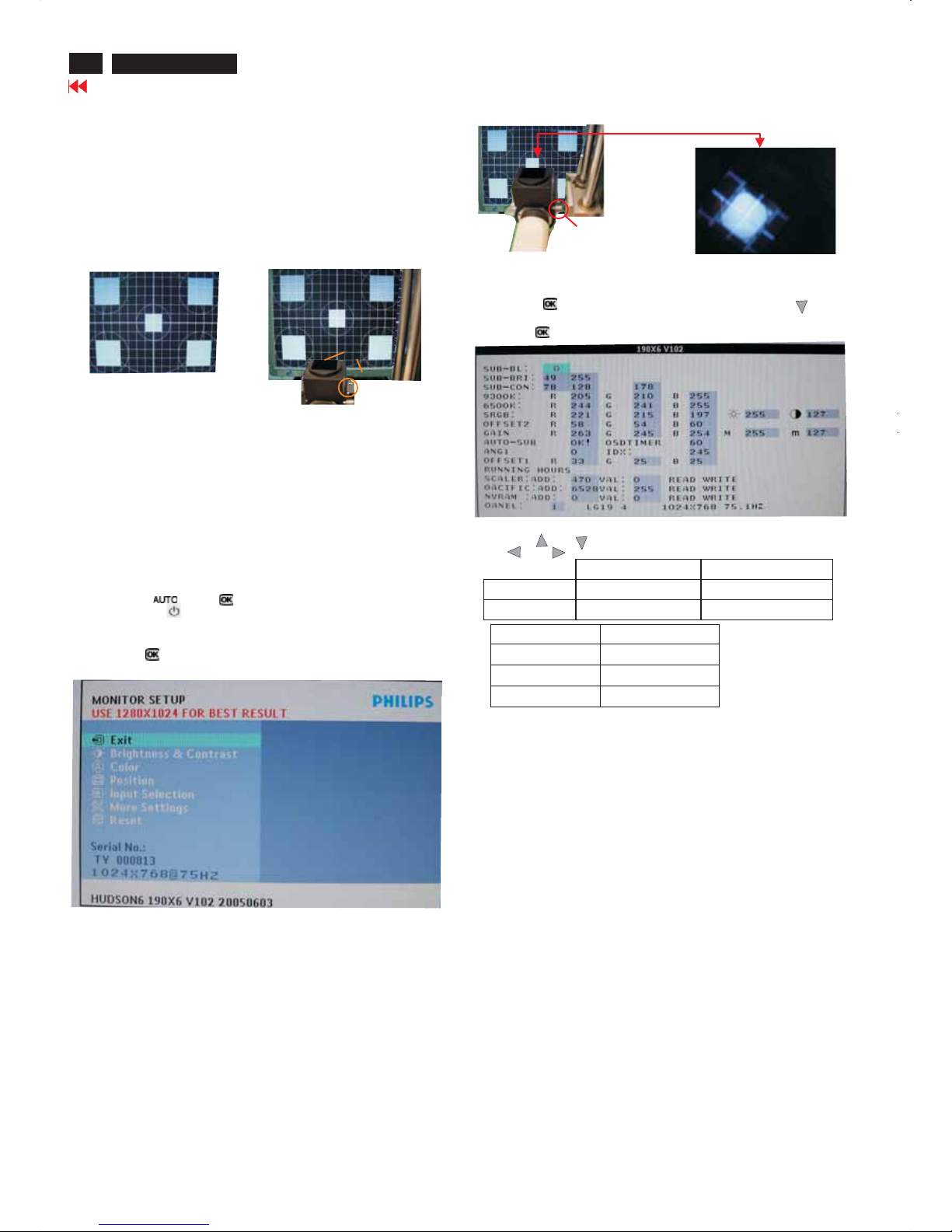
4. Access Factory Mode
How to get into Factory Mode Menu
Step1:
Turn off monitor.
Step2:
[Push AUTO" "& OK ""buttons at the same time and hold it]
+[Press power ""button untill comes out "Windows screen" ]
=> then release all buttons
Step3:
Press OK ""button, bring up Factory mode indication as shown
in Fig3.
Fig. 3
10. Setting pattern to full white picture
11. Press button, then select factory mode indicator by"" ""
button
12. Press""button to bring up submenu windows as below:
13. Press ""or ""button to select R GB. Change the value by
""or ""key until the X,Y co-ordinates as below
Fig.4
15. EEPROMpresetting(B)
After finishing all the adjustment, set:
Brightness control to 100%
Contrast control to 50%
OSD position at middle of screen
COLORadjusts to 6500K color.
9300°K6500°K
x (center) 0.283 ± 0.020 0.313 ± 0.020
y (center) 0.297 ± 0.020 0.329 ± 0.020
sRGB
x(center) 0.313 ± 0.020
y(center) 0.329 ± 0.020
Ynits 180 ± 10
Display Adjustment

15
190X6&170X6 LCD
Go to cover page
Trouble Shooting
CommonProblems
Havingthis problemCheck these items
No Picture
(Power LED not lit)
· Make sure thepower cordispluggedinto the
power outlet and into the back of the monitor.
· First, ensure that thepower button on the frontof
the monitor is in the OFF position, then press itto
the ON position.
No Picture
(Power LED is amber or yellow)
· Make sure thecomputer is turned on.
· Make sure the signal cable is properly connected
to yourcomputer.
· Check to see if the monitor cable hasbentpins.
· The EnergySaving feature maybeactivated
Screensays
· Make sure the monitor cable is properly
connected to yourcomputer.(Alsorefer to the
QuickSet-UpGuide).
· Check to see if the monitor cable hasbentpins.
· Make sure thecomputer is turned on
Screensays
· Make sure theverticalsyncofinput signalis
within therange of56~75Hz.
· Change therefresh rate to 56~75Hz within 10
minutes.
· Re-power onmonitor to start over again if you
failed to change therefresh rate within 10
minutes.
AUTO buttonnot working properly
· The Auto Functionisdesignedfor useon
standardMacintosh or IBM-compatible PCs
running Microsoft Windows.
· It maynot work properly if using nonstandardPC
or video card.
· The AUTO adjustment doesnot functionwhen
digitalinput is usedfor display
Imaging Problems
Display positionisincorrect
· Press the Auto button.
· Adjustthe image positionusingthe Horizontal
Position and/or VerticalPositioninOSDMain
Controls.
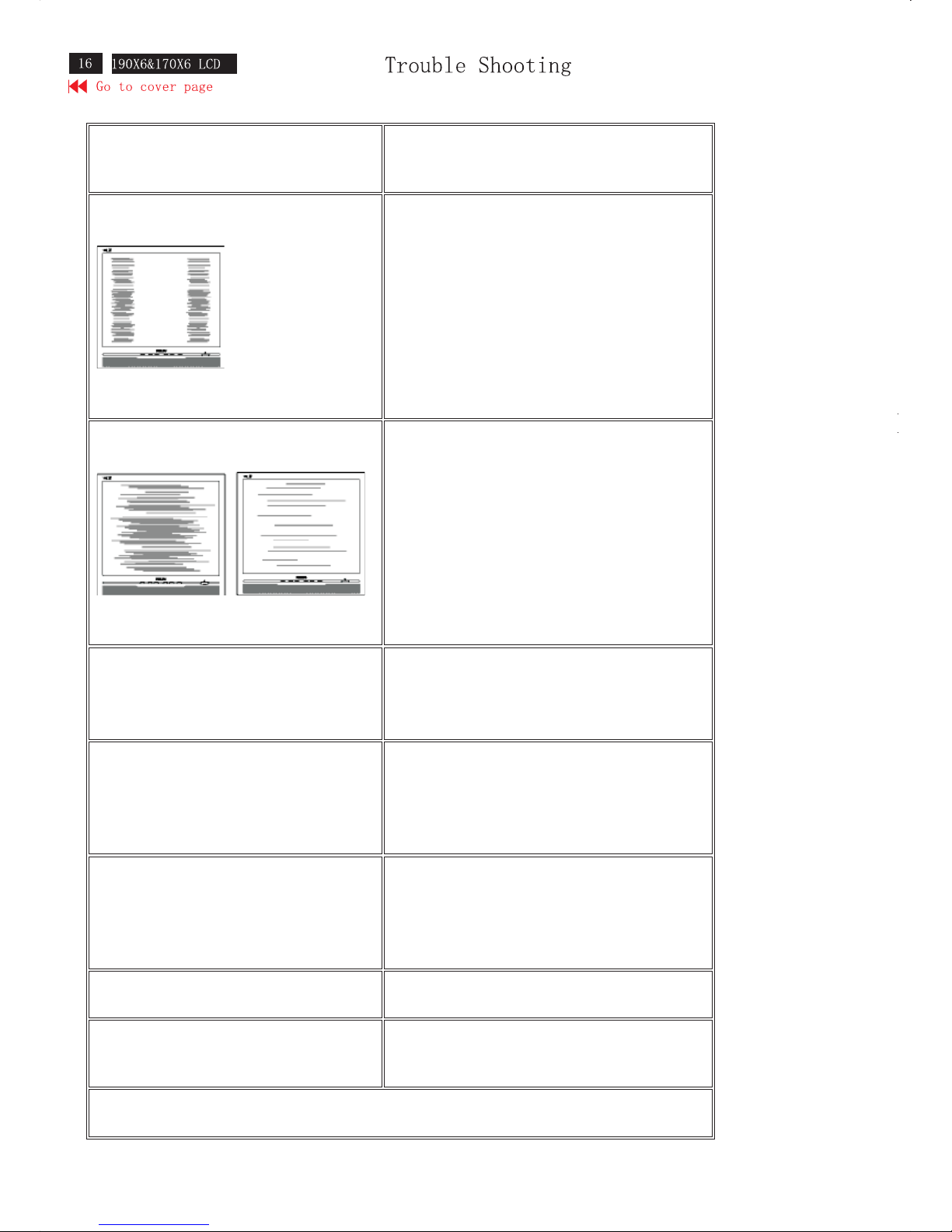
Image vibrates on the screen
· Check that the signal cable is properly connected
to the graphics board or PC.
Vertical flicker appears
· Press the Auto button.
· Eliminate the vertical bars using the Phase/Clock
of More Settings in OSD Main Controls.
Horizontal flicker appears
· Press the Auto button.
· Eliminate the vertical bars using the Phase/Clock
of More Settings in OSD Main Controls.
The screen is too bright or too dark Adjust the contrast and brightness on OSD Main Controls.
(The backlight of the LCD monitor has a fixed life span.
When the screen becomes dark or begins to flicker, please
contact your dealer).
An after-image appears
· If an image remains on the screen for an extended
period of time, it may be imprinted in the screen
and leave an after-image. This usually disappears
after a few hours
An after-image remains after the power has been
turned off.
· This is characteristic of liquid crystal and is not
caused by a malfunction or deterioration of the
liquid crystal. The after-image will disappear after
a peroid of time.
Green, red, blue, dark, and white dots remains The remaining dots are normal characteristic of the liquid
crystal used in today’s technology
LightFrameTMdoesn't work
· Press the Auto button.
· Activate the LightFrame
TM
software again.
For further assistance, refer to the Consumer Information Centers list and contact your local Philips distributor
17
190X6&170X6 LCD
Go to cover page
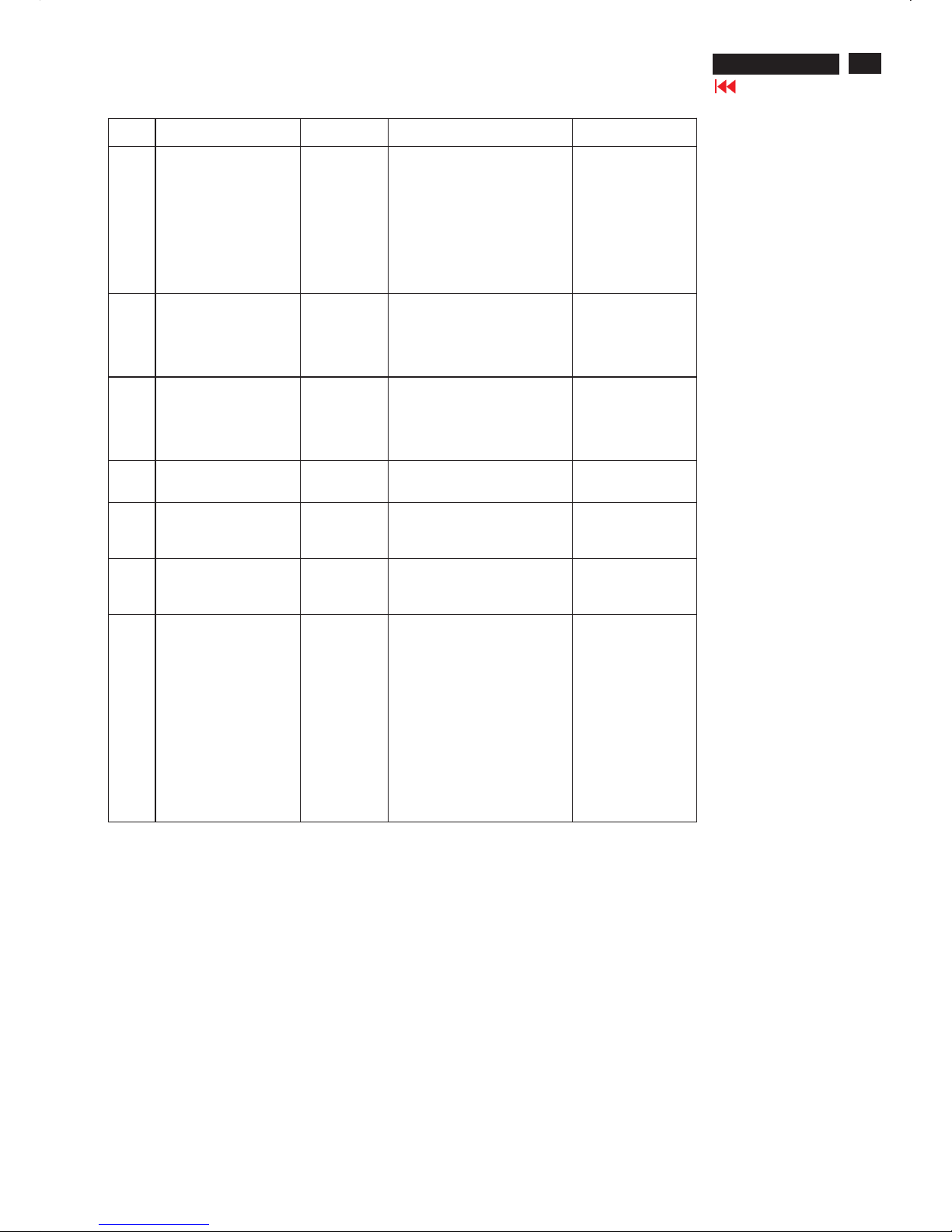
Warning message
Item Attention Signals DisplayTime Condition Attention off
1Can not display this
video mode, change
computer display input
to 1280x1024@60Hz
30 mins This warning appears when the
inputsignalfrom yourcomputer
is not in a standard video mode
or is outof the monitor s
scanning range.After 30 mins,
monitor enters sleeping mode.
2 NO VIDEO INPUT 30.mins This message ap pears when
thereisnosignal input but with
cable while AC or DC power on.
After 30 mins, monitor enters
sleeping mode
3 CHECK CABLE
CONNECTION
30 mins This message appears when a
signal cableisdisconnected
while monitor is working.After
30 mins, monitor enters sle eping
mode.
4Enter sleep mode 3secs This message appears when
monitor is about to enter power
saving mode
5 Waiting for automatic
adjustment
Till automatic
adjustment
finished
This message is displayedwhen
auto adjustment button is
pressed. It disappears when
auto adjustments are completed
6Use 1280x1024 for best
result
Ontopof
OSD main
menu
This message will showupat
thetopof the OSD main menu in
red color when theinput
resolution is not the 1280x1024
7OSDmain controls
locked
3secs/or till
OSD main
controls
unlocked
appear
This message will appear 3
secondstoindicate the OSD
MAIN CONTROLS status when
to lock or un-lock it by pressing
MENU(OK) button for more
than 10 seconds whilethere is
video input from PC. This
function provides thealternative
that user can l
ock all the OSD
main control in case user don’t
want the FOS performance
setting to bechanged, for
instance,during commercial
exhibition.
18
190X6&170X6 LCD
Go to cover page
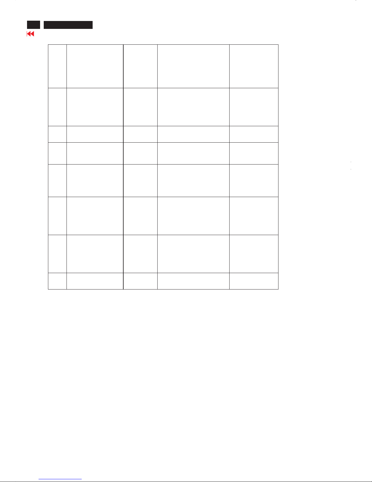
Warning Message
8 OSD MAIN CONTROLS
UNLOCKED
3 secs This message will appear 3
seconds to indicate the OSD
MAIN CONTROLS status when
to un-lock it by pressing
MENU(OK) button for more
than 10 seconds while there is
video input from
PC
9 THISIS85HZ
OVERSCAN, CHANGE
COMPUTER DISPLAY
INPUT TO
1280X1024@60HZ
10 mins This message will appear 5
seconds in every 60 seconds for
10 minutes when the input of PC
video timing is at 85Hz mode.
Remark: AUTO is still functional
in this mode
10 the window of
MONITOR SETUP
60 secs This message will appear when
the OK button is pressed.
11 the w ind ow o f
BRIGHTNESS
60 secs This message will appear when
the BRIGHTNESS button is
pressed.
12 SELECTED INPUT NOT
AVAILABLE
3 secs When just one input (analog or
digital), press input switch or
hot key, then after show this
warning message 3 sec, return
to original input.
13 SECURITY
PROTECTED, THIS
MONITOR IS GOING
TO ENTER POWER
SAVING MODE IN 15
SECONDS
15 secs This warning appears when the
security was set ON and
someone takes out from the
client PC
14 SECURITY
PROTECTED, THIS
MONITOR IS GOING
TO ENTER POWER
SAVING MODE IN 15
SECONDS
1 mins This warning appears when
Asset management Server
sends power saving command
to client PC
15 the window of
VOLUME
60 secs This message will appear when
the VOLUME button is pressed.
""
"" ""
""
"
"
""
""
19
190X6&170X6 LCD
Go to cover page
Electrical instructions(190X6)
1. General points
1.1 During thetestandmeasuring, supply a distortion free AC mains
voltage to the apparatus via an isolated transformer with low internal
resistance.
1.2 All measurements mentionedhereafter are carried out at a normal
mains voltage (90 - 132 VAC for USA version, 195-264VACfor
EUROPEAN version, or 90 -264 VAC for the model withfull range
power supply, unless otherwise stated.)
1.3 A
ll voltages are to be measured or appliedwith respect to ground,
unless otherwise stated.
Note:don‘tuseheat-sink as ground.
1.4 Thetesthas to be done on a complete set including LCD panel
After 30 minutes warm-up at least in a roomwith temperature of
25 +/- 5 degree C.
1.5 All values mentioned in these test instruction are only applicable
of a well aligned apparatus,with correct signal.
1.6 The letters symbols (B)and
(S)placedbehind thetest
instruction denotes (B): carried out 100% inspection at assembly line
(S): carried out test by sampling
1.7 The white balance (color temperature) has to be
tested in subdued lighted room.
1.8 Repetitive power on / off cycle are allowed except it
shouldbeavoidedwithin6sec.
2. Input s ignal
2.1 Signal type
2.1.1 Video signal input
Signal source: pattern generator format as the Spec
Reference generator:QuantumData 802G
The input signals can be applied in two different modes:
1).VESA Analog
Thevideo input consists of red, green, andblue signals.
Thevideo signals are analog levels,where 0V
correspondstoblack and700mV is the maximum signal
amplitude.Input impedance of video pins is 75 ohm +/- 1%.
2).Intel DVI Digital
Input signal:Four channel TMDS signals
2.1.2 Sync signal input
The capability of sync signal inputs shall include separate
sync, composite sync and sync on green. input impedance:
2k2 ohms The signals are defined as follow:
Separate sync TTL level,Positive/Negative
Composite s
ync TTL level,Positive/Negative
Sync on green H-sync TTL level,Positive/Negative
Signal source: pattern generator format as the Spec
Reference generator:QuantumData 802G
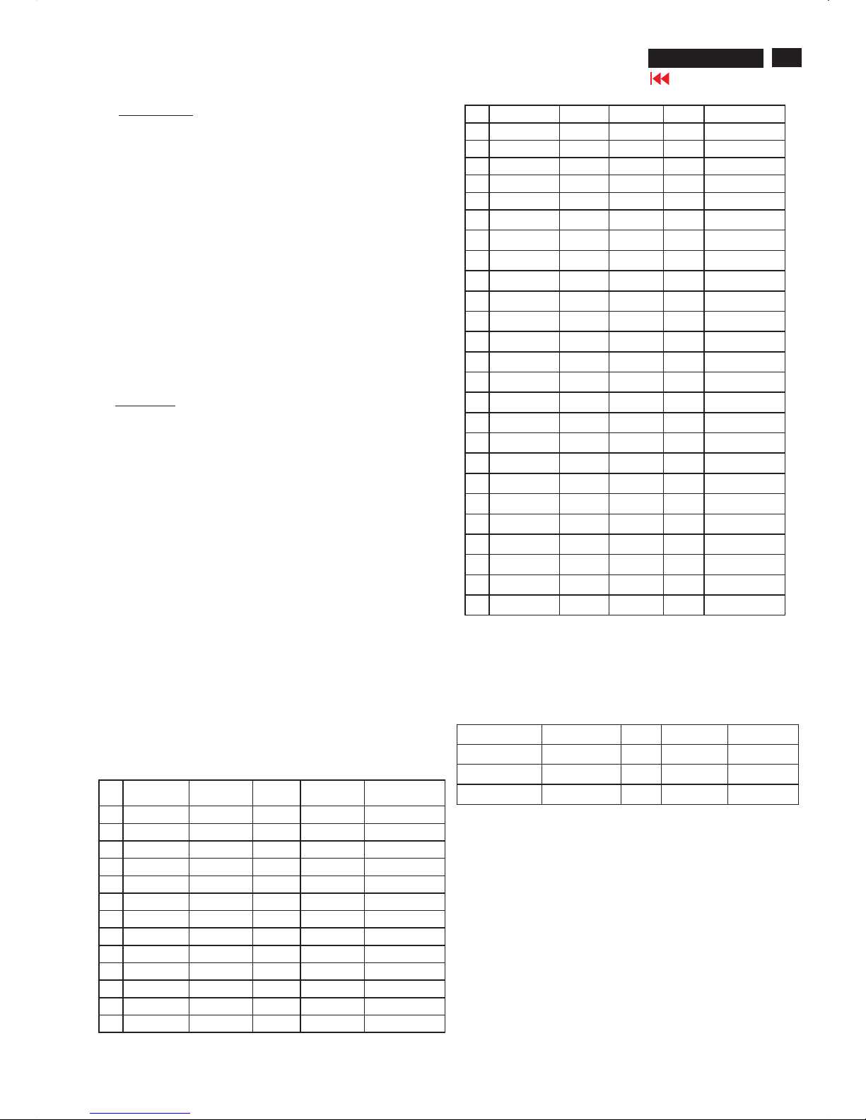
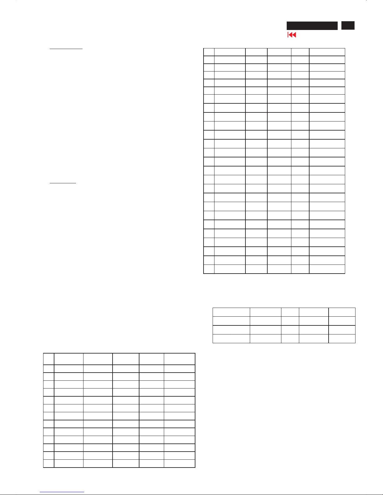
2.2 Input signal mode Pre-set 34 modes
PRESETVIDEORESOL UTION
#Resolution H-
Frequency
Pixel
rate
V-
Frequency
Comment
1640X350 31.5K 25.175 70Hz IBM VGA 10h
2720X400 31.5K 28.322 70Hz IBM VGA3h
3 640X480 31.5K 25.175 60Hz
4 640X480 35.0K30.24 67Hz
5 640X480 37.9K31.5 72Hz
6640X480 37.5K 31.501 75Hz
7 640X480 43.3K 36 85Hz
8800X600 35.2K 36 56Hz
9 800X600 37.9K4060Hz
10 800X600 48.1K50 72Hz
11 800X600 46.9K49.498 75Hz
12800X600 53.7K 56.251 85Hz
13 832X624 49.7K 57.28 75Hz MAC
14 1024X768 48.4K 65 60Hz
15 1024X76856.5K 75 70Hz
16 1024X768 60.0K 78.75 75Hz
17 1024X768 61.1K 83.096 76Hz IBM XGA-2
18 1024X768 68.7K 94.5 85Hz
19 1152X864 54.0K79.960Hz non-VESA
201152X864 67.5K 108 75Hz
211152X864 63.9K 94.5 70Hz non-VESA
22 1152X87068.7K 100 75Hz MAC
23 1152X900 61.8K 92.94 66Hz SUN Mode IV
24 1152X900 71.8K 10876Hz SUN Mode II
25 1280X960 60.0K 108 60Hz
261280X960 75.0K 129.895 75Hz non-VESA
27 1280X1024 64.0K 108 60Hz
28 1280X1024 71.7K 117 67Hz SUN Mode V
291280X1024 76.0K 130.223 72Hz DOS/V
301280X1024 80.0K 135 75Hz
311280X1024 81.1K 135.00876Hz SUN Mode I
32 688X556 31.3K 27 50Hz TV-PAL
33 960X720 44.76K 57.58 60Hz
34 960X720 56.4K 72.42 75Hz
2.3 Allowed85Hzoverscan signal mod especified
Once the signal input ofPCis 85Hz, this monitor is able to display at
least for 10 minutes.An attention signal appears and shows THIS
IS 85HZ OVERDRIVE, CHANGE COMPUTER DISPLAY INPUT TO
1280X1024 @ 60 HZ
Dot rate (MHz) H. Freq (KHz) Mode Resolution V. Freq (Hz)
36.000 43.269 VESA 640 *480 85.008
556.250 53.674 VESA 800 * 600 85.061
94.500 68.677 VESA 1024 * 768 84.997
3. Power Supply (S)
Setup the AC I/P at 90VAC, andOutput DC loading at 12V 3.7 Amp,
5V 2.1 Amp,The DC output voltages are 5V +/-0.25V and 12V+/-1.2V.
4. DisplayAdjustm ent
4.1 Access to factorymode(RS232) in auto-alignment system
Thecommunication protocol switch to RS232 .
4.2 Auto color adjustment (B)
Apply a640x480/31kHz/60Hz signal w
ith 16 gray pattern, set
Brightness to 100%, and contrast to 50%. Adjust the R. G.Boffset,
and gain to calibrate the color smoothly and 64-gray level
distinguishable.
Check all pre-setting 34 modes.
20
190X6&170X6 LCD
Go to cover page
Electrical instructions(190X6)
4.2 Auto color adjustment (B)
Apply a 640x480/31kHz/60Hz signal with 16 gray pattern,
set brightness to 100%,and contrast to 50%.
Adjust the R. G. B offset, and gain to calibrate the color
smoothly and 64-gray level distinguishable.
Check all pre-setting 34 modes.
4.3 Adjustment of WHITE-D (B)
Apply a 1280*1024 / 60Hz signal with white pattern,
set brightness to 100%, and contrast to 50%. Adjust
the R, G, B Sub-Gain, for the screen center, the 1931
CIE chromaticity (X, Y) co-ordinates shall be;
Use Minolta CA-110 for color coordinates and luminance check.
Luminance is > 200 Nits in the center of the screen in the panel
color when brightness is set to 100% and contrast is set to 100%.
4.4 Adjustment of sRGB
Apply a 1280*1024 / 60Hz signal with white pattern, set
brightness to 100%, and contrast to 50%. Adjust the
R, G, B Sub-Gain, for the screen center, the 1931 CIE
chromaticity (X, Y) co-ordinates shall be;
sRGB
x(center) 0.313 ± 0.020
y(center) 0.329 ± 0.020
Ynits 180 ± 10
4.5 EEPROM preset ting (B)
After finishing all the adjustment, set:
Brightness to 100%
Contrast to 50%
OSD position at middle of screen
COLOR ADJUST to 6500K color temperature.
Stand-Alone set to Off
9300°K 6500°K
x (center) 0.283 ± 0.020 0.313 ± 0.020
y (center) 0.297 ± 0.020 0.329 ± 0.020
21
190X6&170X6 LCD
Go to cover page
Electrical instructions(170X6)
1. General points
1.1 During thetestandmeasuring, supply a distortion free AC mains
voltage to the apparatus via an isolated transformer with low internal
resistance.
1.2 All measurements mentionedhereafter are carried out at a normal
mains voltage (90 - 132 VAC for USA version, 195 -264VACfor
EUROPEAN version, or 90 -264 VAC for the model withfull range
power supply, unless otherwise state
d.)
1.3 All voltages are to be measured or appliedwith respect to ground,
unless otherwise stated.
Note:do not use heat-sink as ground.
1.4 Thetesthas to be done on a complete set including LCD panel after
30 minutes warm-up at least in a roomwith temperature of25+/-5
degree C.
1.5 All values mentioned in these test instruction are only applicable
of a well aligned apparatus,with correct signal.
1.6 The letters symbols (B
)and (S)placedbehind thetest
instruction denotes
(B): carried out 100% inspection at assembly line
(S): carried out test by sampling
1.7 The white balance (color temperature) has to betested in subdued
lighted room.
1.8 Repetitive power on / off cycle are allowed except it shouldbe
avoidedwithin 6 sec.
2. Input signal
2.1 Signal type
2.1.1 Video signal input
Signal source: pattern generator format as the SPEC
Reference generator:QuantumData 802G
The input signals can be applied in two different modes:
1).VESA Analog
Thevideo input consists of red, green, andblue signals.
Thevideo signals are analog levels,where 0V correspondsto
black and 700mV is the maximum
signal amplitude.Input
impedance of video pins is 75 ohm +/- 1%.
2).Intel DVI Digital
Input signal:Four channel TMDS signals
2.1.2 Sync signal input
The capability of sync signal inputs shall include separate sync,
composite sync sync on green. input impedance:2k2ohms
The signals are defined as follow:
Separate sync TTL level,Positive/Negative
Composite sync TTL
level,Positive/Negative
Sync on green H-sync TTL level,Positive/Negative
Signal source: pattern generator format as thespec
Reference generator:QuantumData 802G
2.2 Input signal mod e
Pre-set 34 modes
PRESET VIDEORESOLUTION
#Resolution H-
Frequency
Pixel rate V-
Frequency
Comment
1640X350 31.5K 25.175 70Hz IBM VGA 10h
2 720X400 31.5K 28.322 70Hz IBM VGA3h
3 640X480 31.5K 25.175 60Hz
4 640X480 35.0K30.24 67Hz
5 640X480 37.9K 31.5 72Hz
6640X480 37.5K 31.501 75Hz
7640X480 43.3K 36 85Hz
8800X600 35.2K 36 56Hz
9800X600 37.9K 4060Hz
10 800X600 48.1K5072Hz
11 800X600 46.9K 49.498 75Hz
12800X600 53.7K56.251 85Hz
13 832X624 49.7K57.28 75Hz MAC
14 1024X768 48.4K 65 60Hz
15 1024X76856.5K 75 70Hz
16 1024X768 60.0K 78.75 75Hz
17 1024X768 61.1K 83.09676Hz IBM XGA-2
18 1024X768 68.7K 94.5 85Hz
19 1152X864 54.0K 79.9 60Hz non-VESA
201152X864 67.5K 108 75Hz
211152X864 63.9K 94.5 70Hz non-VESA
22 1152X870 68.7K 100 75Hz MAC
23 1152X900 61.8K 92.94 66Hz SUN Mode IV
24 1152X900 71.8K 108 76Hz SUN Mode II
25 1280X960 60.0K 108 60Hz
261280X960 75.0K 129.895 75Hz non-VESA
271280X1024 64.0K 108 60Hz
28 1280X1024 71.7K 117 67Hz SUN Mode V
29 1280X1024 76.0K 130.223 72Hz DOS/V
301280X1024 80.0K 135 75Hz
311280X1024 81.1K 135.008 76Hz SUN Mode I
32 688X556 31.3K 27 50Hz TV-PAL
33 960X720 44.76K57.58 60Hz
34 960X720 56.4K 72.42 75Hz
2.3 Allowed85Hzoverscan sig nal mo despecif ied
Once the signal input ofPCis 85Hz, this monitor is able to display at
least for10 minutes.An attention signal appears and shows THIS IS
85HZ OVERDRIVE, CHANGE COMPUTER DISPLAY INPUT TO
1280X1024 @ 60 HZ
Dot rate (MHz) H. Freq (KHz) Mode Resolution V. Freq (Hz)
36.000 43.269VESA 640 *480 85.008
556.250 53.674VESA 800 * 600 85.061
94.500 68.677 VESA 1024 * 768 84.997
3.power Supply (S)
3.1Setup the AC I/P at 90VAC, andOutput DC loading at 12V 3.7 Amp,
5V 2.1 Amp,The DC output voltages are 5V +/- 0.25V and 12V+/-1.2V.
4. DisplayAdjustment
4.1 Access to factorymode(RS232) in auto-alignment system
Thecommunication protocol switch to RS232 .
4.2 Auto color adjustment (B)
Apply a640x480/3
1kHz/60Hz signal with 16 gray pattern, set brightness
to 100%, and contrast to 50%.
Adjust the R. G.Boffset, and gain to calibrate the color smoothly and
64-gray level distinguishable.Check all pre-setting 34 modes.
22
190X6&170X6 LCD
Go to cover page
Electrical instructions(170X6)
4.3 Adjustment of WHITE-D (B)
Apply a 1280*1024 / 60Hz signal with white pattern, set brightness
to 100%, and contrast to 50%. Adjust the R, G, B Sub-Gain, for the
screen center, the 1931 CIE chromaticity (X, Y) co-ordinates shall be;
Use Minolta CA-110 for color coordinates and luminance check.
Luminance is > 200 Nits in the center of the screen in the panel color
when brightness is set to 100% and contrast is set to 100%.
4.4 Adjustment of s RGB
Apply a 1280*1024 / 60Hz signal with white pattern, set brightness
to 100%, and contrast to 50%. Adjust the R, G, B Sub-Gain, for the
screen center, the 1931 CIE
chromaticity (X, Y) co-ordinates shall be;
sRGB
x(center) 0.313 ± 0.020
y(center) 0.329 ± 0.020
Ynits 180 ± 10
EEPROM pr esett ing (B )
After finishing all the adjustment, set:
Brightness to 100%
Contrast to 50%
OSD position at middle of screen
COLOR ADJUST to 6500K color temperature
Stand-Alone set to Off
9300°K 6500°K
x (center) 0.283 ± 0.020 0.313 ± 0.020
y (center) 0.297 ± 0.020 0.329 ± 0.020
23
190X6&170X6 LCD
Go to cover page
LightFrame DR
TM
LightFrameTMDigital Reality(LightFrameTMDR)for Windows
Introduction
Philips LightFrame
TM
DR feature enrichesyourphotoand video
experience with preset modes idealfor your favorite applications:
Internet,TV/video viewing, photos and gaming.The LightFrame
TM
DR engine optimizesbrightness, sharpness, contrast, color,JPG
noise for photos and skin tone for videos.
Installation
Firstthingsfirst:Philips LightFrame
TM
DR only works with monitors
specially builttousethissoftware.Earlier Philips monitors or other
manufacturers' monitorswill not workwith thisspecialsoftware.This
software is only for use with Philips 170X6,170P6 and 190X6,190P6
monitors.You can identify compatibl
e Philips monitorsbythe
LightFrame logo on the frontof the monitor.
LightFrameTMDR works with true Windows-based programs and
DOS-based programs that operate in a Windows environment.
It doesnot workwith DOS-based programs operatingonly in a
DOS environment.
Tocontrol the LightFrame
TM
DR feature inyourmonitor,you'll
wantinstall the LightFrame
TM
DR applicationfound on thisCD-ROM.
Toinstall LightFrame
TM
DR, place the CDinyour CD-ROM drive.
When the CDmenu appears onyour screen,
1) select preferredlanguage 2) select modelnumber (170X6 or 190X6)
3) click on Install LightFrame
TM
Digital Reality.
Follow the on-screen prompts to properly install the program.The
software checks to see ifyou have a compatiblemonitor.You must
agree to the licenseterms in order to install the software.
After installation, the LightFrame
TM
DR shortcuticon automatically
Appears at your desktop, click it to load the controlbar onscreen.
Use Tips
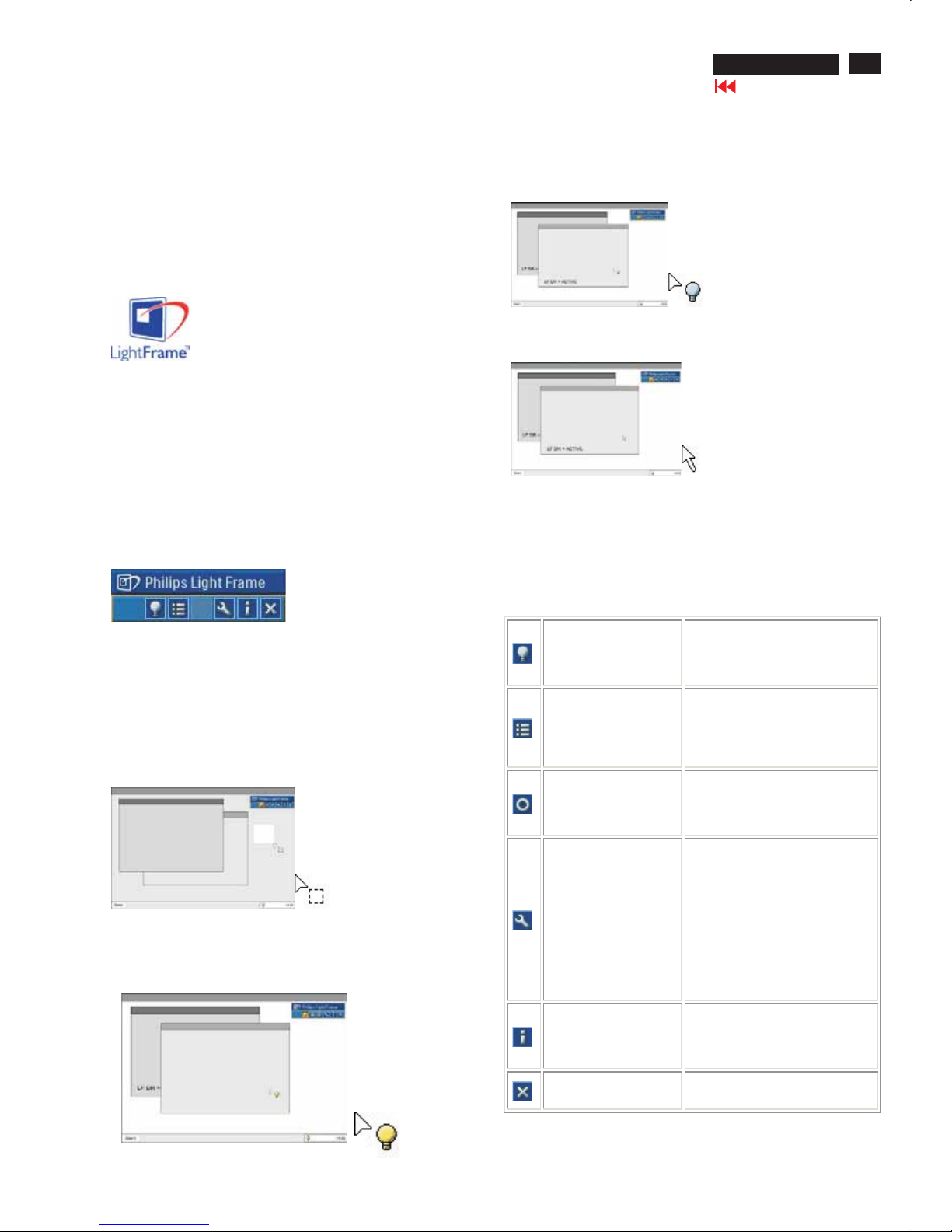
1. Cursor with a yellow light bulb versus a blue light bulb
Yourmouse pointer takes the shape of a light bulb to indicate that
LightFrame
TM
DR is ready to activate or deactivate a target window that
contains photos, videos or other content that canbeenhanced. A yellow
light bulb means that you are movingoverawindowwhere LightFrame
TM
DR canbeactivated. Click on the window to activate enhancement.A
blue light bulb appearswhen movingoveran activatedwindow. Click on
the window to de-activate LightFrame
TM
DR.
Cursor examples
Here is a listof LightFrame
TM
DR cursors.
This is the defaultcursor displayedwhenyou move over a non-
LightFrame
TM
DR enhancedwindow or area.Clickingand dragging
this cursor over a Window or area activates LightFrameTM DR
enhancement.
Yourcursor becomes a yellowlight bulb when it passes over a
non-active window to indicate that LightFrame
TM
DR canbe
activated in the selectedwindow. Click to activate LightFrame
TM
DR
in the selectedwindow. To activate LightFrame
TM
DR simultaneously in
atotal ofuptoeightwindows, click on the selectedwindows one-by-one
whilepressingtheShift key.
Yourcursor becomes a blue light bulb when it passes over an acti ve
LightFrame
TM
DR window. Click to deactivate LightFrameTMDR in the
selectedwindow.
The normal cursor is restored after you click on a target withoutpressing
the shift key or after youdragarectangle.
2. LightFrame
TM
DR controlbar
The LightFrame
TM
DR controlbar appears at the top ofscreen after any
LightFrame
TM
DR function is activated.The controlbar is another upgrade
that helpsyou run all LightFrame
TM
Digital Reality's neat,newfeatures.
The illustrationbelowdescribes the tasks each button performs.
To drag the controlbar to any preferred area ofyour screen, leftclick the
LightFrame
TM
DR logo.(See examplesbelow) This area isnot a button.
Activate or deactivate
LightFrame
TM
DR icon
Turns LightFrame
TM
DR on and off.
When LightFrame
TM
DR is
active in a selectedwindow, the
icon changesfrom bluetoyellow.
Activate or deactivate
the modemenu icon
The defaultmodemenu icon
appearswhennomodeisselected.
Whenyouselect the photo,Internet
or other mode, the iconfor the
selected mode appears.
Deactivate all
LightFrame
TM
DR
windows icon
Deactivates all LightFrame
TM
DR
windows. Thisfunction is only
visible when LightFrame
TM
DR
windows are active.
Properties icon
Provides access to the Properties
menu, which includes these
options:
LightFrame
TM
DR auto start:Yes/no
Position: LightFrame
TM
DR Always
on top Warningmessages: On/off
Target selection: Automatic/manual
Monitor selection: Choseamong
twomonitors connected to the
same PC Place LightFrame
TM
DR
icon in the taskbar:Yes/no
Infomodeicon
Activates and deactivates the Info
mode,which provides information
abouttoolbar and menu items as
well as access to Help files.
Exit icon
Click to exit the LightFrame
TM
DR
controlbar
3. Optimizing LightFrameTMDR settings
Here's how to optimize LightFrame
TM
DR settings to your personal
preferences:
2.The settings menu
3. Optimizing LightFrameTMDR settings
Here's how to optimize LightFrame
TM
DR settings to your personal
preferences:
1.Select your desired mode from the mode Menu. Click to open the mode.
24
190X6&170X6 LCD
Go to cover page
LightFrame DR
TM
3.Change settings by pulling the color bar or pressing the
plus (+) or minus (-) button to move incrementally to the
desired levels.
When you're finished, click on the Mode icon to exit the menu.
4. LightFrame
TM
Hot Key
The LightFrame
TM
Hot Key is located at front of LightFrameTMDR
monitor. The blue LED is on when LightFrame
TM
is activated and off
when the feature is deactivated. A touch on the Hot Key quickly
provides full screen enhancement in your choice of the Internet,
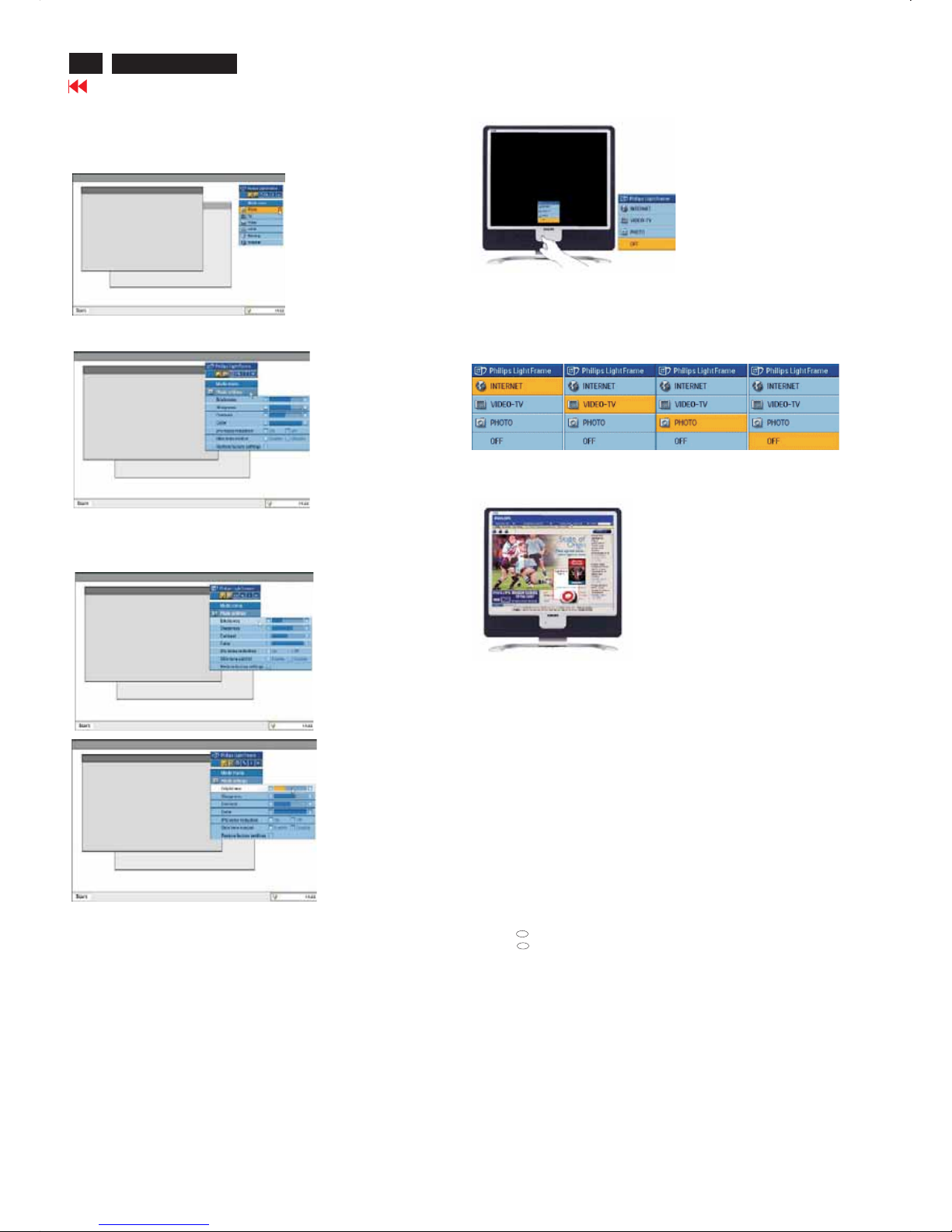
Photo or Video-TV mode.
When you touch the front button, a small OSD window opens on
your screen directly above the button location.
Use this screen to select the best full screen mode for the application
you're working with. Press continuously on the Hot Key to scroll through
the available options.
1) When you touch the LightFrameTMHot Key, an OSD window opens.
Touch the button continually to scroll among the available Internet,
Photo and Video-TV modes. As a mode becomes available for selection,
its color changes from blue to yellow. Once you reach the desired mode,
remove your finger from the Hot Key. After three seconds, the mode you
have selected will be confirmed and the OSD window will automatically
close.
2) Touch the LightFrameTMDR Hot Key for three seconds to enter
the LightFrame
TM
demo mode. To exit the demonstration mode, press
the hot key again.
5. Language
While English is the default language of LightFrame
TM
DR, Dutch,
French, German, Italian, Portuguese, Spanish, Simplified Chinese,
Traditional Chinese and Korean are supported. LightFrame
TM
DR
will detect the language of computer system OS and select the
language automatically.
Notes
Philips LightFrame
TM
DR only works with monitors specially built to
use this software. If LightFrame
TM
DR detects that your monitor is not
LightFrame
TM
DR-compatible, a message appears on the monitor
screen. If you see this message, you can abort or continue the
installation; however, if you continue the installation, LightFrame
TM
DR
will probably not work on the monitor.
How to us e Lig htFr ame
TM
DR
After installation, LightFrame
TM
DR shortcut icon appears on your
screen whenever the computer is started.
To learn more about using LightFrame
TM
Digital Reality, please refer
to the help information, which is available after installation.
Compatibility
This version of LightFrame
TM
DR is compatible with:
Windows XP
Windows 2000 Professional Edition with Service Pack 2
How to download your upgraded LF DR Installation file
Visit http://www.philips.com/support
R
R
25
Pin No. Description
1 T.M.D.S. data22 T.M.D.S. data2+
3 T.M.D.S. data2 shield
4 No Connect
5 No Connect
6 DDC clock
7 DDC data
8 No Connect
9 T.M.D.S. data110 T.M.D.S. data1+
11 T.M.D.S. data1 shield
12 No Connect
13 No Connect
14 +5V Power
15 Ground (for +5V) - Cable detect
16 Hot plug detect
17 T.M.D.S. data018 T.M.D.S. data0+
19 T.M.D.S. data0 shield
20 No Connect
21 No Connect
22 T.M.D.S clock shield
23 T.M.D.S. clock+
24 T.M.D.S. clock-
190X6&170X6 LCD
DDC Instructions
Go to cover page
To Monitor
D-sub/DVI cable
DC 8~12V
To Printer port
Power
indicator
To Monitor
D-sub cable
DC 8~12V
To Printer port
Power
indicator
General
DDC Data Re-programming
Analog DDC IC, & EEPROM
Additional information
In case the DDC data memoryICormain EEPROM which storage all
factory settings were replaced due to a defect, the serial numbers have
to be re-programmed"".
Itisadvised to re-soldered DDC IC and main EEPROMfrom the old
board onto the new board if circuit board have been replaced, in this
case the DDC data does not need to be re-programmed.
Additional information about DDC (Display Data Channel) may be
obtained from Video Electronics Standards Association (VESA). Extended
DisplayIdentification Data(EDID) information may be also obtained from
VESA.
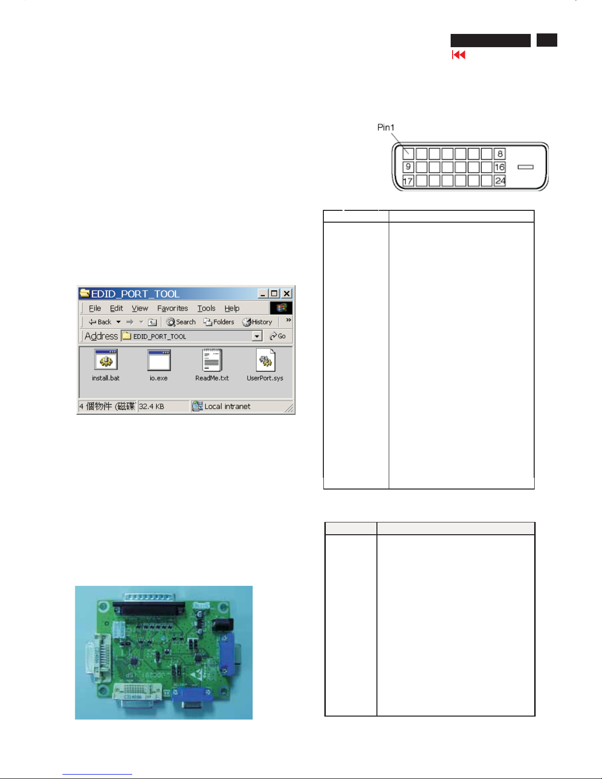
1. An i486 (or above) personal com
puter or compatible.
2. Microsoft operation systemWindows 95/98 .
Y o Install the EDID_PORT_Tool under Win2000/XP.As
Fig.1.
A. Copy the "UserPort.sys" to C:\WINNT\system32\drivers(win2000)
C:\WINDOWS\system32\drivers(winXP)
B. Running " io.exe" everytime,Before you start to programming
edid data .
4. DDC 2BI-ISP TOOL:
I
nclusion :
A. DDC2BI-ISP TOOL(3138 106 10396) x1 (as Fig. 2)
B. Printer cable x1
c. (D-Sub) to (D-Sub) cable x2
D. D-SUB to DVI cable X1
Note: The EDID46.EXE is a windows-based program, which cannot
be run in MS-DOS.
System and equipment requirements
ou havet
3. EDID45.exe program .
Fig. 2Fig. 2
Fig. 1Fig. 1
Pin Assignment
The digital only connector contains 24 signal contacts organized in
three rows of eight contacts. Signal pin assignments are listed in the
following table:
Fig. 3Fig. 3
Fig. 4Fig. 4
Input analog D-sub connector pin assignment
PINNo. SIGNAL
1 Red video input
2Greenvideo input / sync on green
3 Blue video input
4GND
5GND–Cabledetect
6 Red video GND
7Greenvideo GND
8 Blue video GND
9 DDC +3.3V or +5V
10 Logic GND
11 GND
12 Serial data line (SDA)
13 H-sync / H+V
14 V-sync
15 Data clock line (SCL)
26
190X6&170X6 LCD
DDC Instructions
Go to cover page
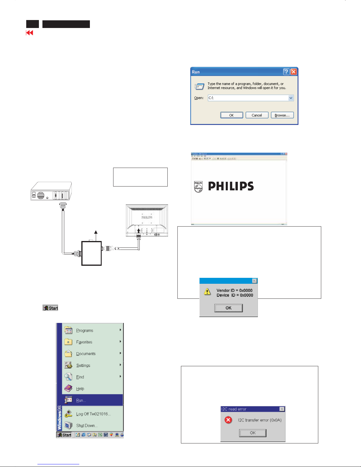
Step 3: Installation of EDID45.EXE
Method 1: Start on DDC program
Start Microsoft Windows.
1. The Program"EDID45.EXE" in service manual cd-rom be copyed to C:\ .
2. Click , choose Run at start menu of Windows as shown
In Fig. 6.
Fig. 6
4. Click button. The main menu appears (as shown in Fig. 8).OK
This is for initialize alignment box.
Fig. 8
Fig. 7
Fig. 9
Note 1: If the connection is improper, you will see the following error
message (as shown in Fig. 9) before entering the main menu.
Meanwhile, the (read EDID) function will be disable. At this
time,
please make sure all cables are connected correctly and
3. At the submenu, type the letter of your computer's hard disk drive
followed by :EDID45 (for example, C:\EDID45, as shown in Fig. 7).
Note 2: During the loading, EDID45 will verify the EDID data which just
loaded from monitor before proceed any further function, once
the data structure of EDID can not be recognized, the following
error message will appear on the screen as below. Please
confirm following steps to avoid this message.
1. The data structure of EDID was incorrect.
2. DDC IC that you are trying to load data is empty.
3. Wrong communication channel has set at configuration setup
1
Configuration and procedure
There are 3 chips contained OSD string, serial number..etc
on the circuit board, main EEPROM which storage all factory settings,OSD
string. DDC IC which storage 128byte EDID data(serial number ..etc.).
Following descirptions are the connection and procedure for Analog
/Digital and main EEPROM can be re-programmed along with
Analog/Digital IC by enable factory memory data write function on the
DDC program (EDID45.EXE).
Initialize alignment box
In order to avoid that monitor entering power saving mode due
to sync will cut off by alignment box, it is necessary to initialize
alignment box before running programming software
(EDID45.EXE). Following steps show you the procedures and
connection.
Step 1: Supply 8-12V DC power source to the Alignment box by
plugging a DC power cord or using batteries.
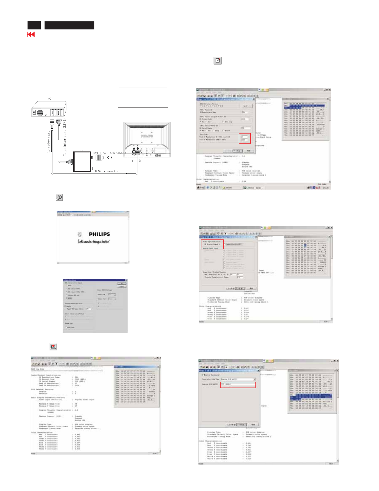
Step 2: Connecting printer cable and D-Sub cable of monitor as Fig. 5
Fig. 5
PC
1=Power connector
2= D-SUB/DVI connector
To printer port (
L
TP1)
DC Power
8-12 V
Fig. 10
Printer
Port
To Monitor
To P C
2
----->
1
----->
Edid45.exe
Edid45.1
27
190X6&170X6 LCD
DDC Instructions
Go to cover page
To Monitor
D-sub/DVI cable
DC 8~12V
To Printer port
Power
indicator
To Monitor
D-sub cable
DC 8~12V
To Printer port
Power
indicator
PC
To printer port (LTP1)
Printer
Port
To Monitor
To P C
To Monitor
D-sub/DVI cable
DC 8~12V
To Printer port
Re-programming Analog DDC IC
Step 1: After initialize alignment box, connecting all cables and
box as shown in Fig. 11
Fig. 12
Step 2: Read DDC data from monitor
1. Click icon as shown in Fig. 11 from the tool bar to bring up
the Channels "Configuration Setup" windows as shown in Fig. 12.
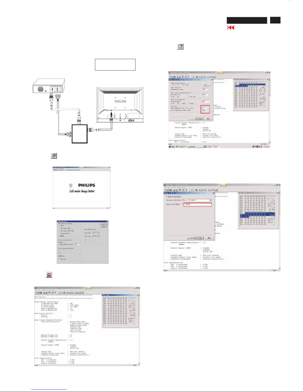
Step 3: Modify DDC data (verify EDID version, week, year)
1. Click (new function) icon from the tool bar, bring up
Step 1 of 9 as shown in Fig. 15 .
EDID45 DDC application provides the function selection and
text change (select & fill out) from Step 1 to Step 9.
Step 4: Modify DDC data (Monitor Serial No.)
Next1. Click to step7, bring up Fig. 16.
- Serial number can be filled up or be changed at this moment.
- Click next,Finish to exit the Step window.
3. Click OK button to confirm your selection.
4. Click icon (Read EDID function) to read DDC EDID data from
monitor. The EDID codes will display on screen as shown in Fig. 14.
Fig. 16
2. Select the DDC2Bi as the communication channel.
As shown in Fig. 13.
Fig. 11
1=Power connector
2=D-SUB connector
Fig. 13
Fig. 14
Fig. 15
Don't close this screen. --->
Select and fill out,
If necessary.
28
190X6&170X6 LCD
DDC Instructions
Go to cover page
To Monitor
D-sub/DVI cable
DC 8~12V
To Printer port
Re-programming Digital DDC IC
Step 1: After initialize alignment box, connecting all cables and
box as shown in Fig. 17
Fig. 18
Step 2: Read DDC data from monitor
1. Click icon as shown in Fig. 18 from the tool bar to bring up
the Channels "Configuration Setup" windows as shown in Fig. 19.
Step 3: Modify DDC data (verify EDID version, week, year)
1. Click (new function) icon from the tool bar, bring up
Step 1 of 9 as shown in Fig. 21 .
EDID45 DDC application provides the function selection and
text change (select & fill out) from Step 1 to Step 9.
Step 4: Modify DDC data (Monitor Serial No.)
Next1. Click , bring up Fig. 22. Then select Digital Signal as below
3. Click OK button to confirm your selection.
4. Click icon (Read EDID function) to read DDC EDID data from
monitor. The EDID codes will display on screen as shown in Fig. 20.
Fig. 22
Fig. 23
2. Select the DDC2Bi as the communication channel.
As shown in Fig. 19.
Fig. 19
Fig. 20
Fig. 21
Fig.17
Printer
Port
To Monitor
To PC
1= DVI connector
2= D-SUB connector
3=Power Plug
3
Don't close this screen. --->
To Monitor
D-sub/DVI cable
DC 8~12V
Select and fill out,
If necessary.
2. Click to step7, bring up Fig. 23.Next
- Serial number can be filled up or be changed at this moment.
- Click Next, Finish to exit the Step window.
29
190X6&170X6 LCD
DDC Instructions
Go to cover page
Step 6: Save DDC data
Sometimes, you may need to save DDC data as a text file for using
in other IC chip. To save DDC data, follow the steps below:
1. Click (Save) icon (or click "file"-> "save as") from the tool bar
And give a file name as shown in Fig. 25.
The file type is EDID46 file (*.ddc) which can be open in WordPad.
By using WordPad, the texts of DDC data & table (128 bytes, hex
code) can be modified. If DDC TEXTS & HEX Table are completely
correct, it can be saved as .ddc flie to re-load it into DDC IC for DDC
Data application.
2. Click .Save
Step 7: Exit DDC program
Pull down the File menu and select Exit as shown in Fig. 26.
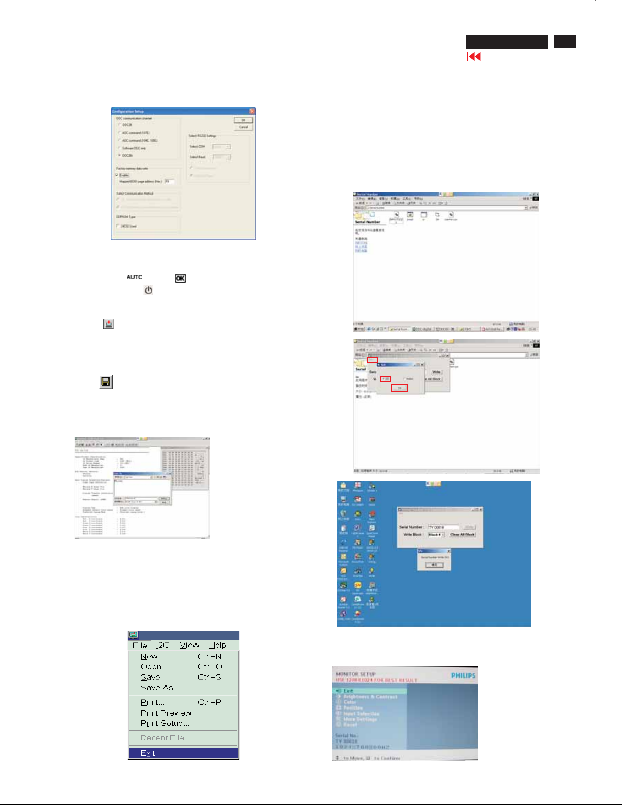
Step 5: Write DDC data
1. Configuration should be as Fig. 24. And press OK.
3. Click (Write EDID) icon from the tool bar to write DDC data.
Fig. 24
Fig. 26
Fig. 25
2. Access Factory Mode
[PushAUTO" "&OK" "buttonsatthesametimeand
holdit]+[Presspower" "buttonuntillcomesout"Windows
screen"] => then release all button
- Turn off monitor.
-
Step9:
-1. Disconnect the monitor power cord and connect it again.
-2. Press the OK button to bring up the OSD main manu.
-3. Re-confirm the serial Number is updated as shown in Fig.31.
Step :8 Modify serial number in OSD
-1. Unzip the serial number.zip to your computer, then open the folder
as shown in Fig.28.
-2. If use Win98 OS, you can execute SN.exe directly.
If use Win2000 or XP OS, first, you must execute install.bat, then
execute SN.exe
-3. Set I2C bus(press the left-top button of operating window) as shown
in Fig.28, then press " SET" button.
-4. Set Block4 as shown in Fig.30
-5. key in new serial number, then press " Write" button as shown in
Fig.30 , Click " WRITE" button.
-6. It will appear" Serial Number Write OK" , Click" Enter" to finish it.
Fig.28
Fig.29
Fig.30
Edid45.1
Fig.31

30
190X6&170X6 LCD
DDC DATA(190X6)
Go to cover page
THE DISPLAYDATA CHANNEL (DDC_2B) CONTENT
INCLUDING (FOR 190X6 ANALOG)
**********************************************************************
EDID log file
*********************************************************************
Vendor/Product Identification
ID Manufacturer Name : PHL
ID Product Code : C010 (HEX.)
ID Serial Number : 1234 (HEX.)
Week of Manufacture : 20
Year of Manufacture : 2005
EDID Version, Revision
Version : 1 Revision : 3
Basic Display Parameters/Features
Video Input Definition : Analog Video Input
0.700V/0.300V (1.00Vpp)
Blank-to-Black Setup
Separate Sync
Composite Sync
Sync on Green
Serration required
Maximum H Image Size : 38
Maximum V Image Size : 30
Display Transfer Characteristic : 2.2(gamma)
Feature Support (DPMS) : Standby
Suspend
Active Off
Display Type : RGB color display
Standard Default Color Space : Primary color space
Preferred Timing Mode : Detailed timing block 1
Color Characteristics
Red X coordinate : 0.636
Red Y coordinate : 0.348
Green X coordinate : 0.292
Green Y coordinate : 0.618
Blue X coordinate : 0.142
Blue Y coordinate : 0.072
White X coordinate : 0.313
White Y coordinate : 0.329
Established Timings
Established Timings I : 720 x 400 @70Hz (IBM,VGA)
640 x 480 @60Hz (IBM,VGA)
640 x 480 @67Hz (Apple,Mac II)
640 x 480 @72Hz (VESA)
640 x 480 @75Hz (VESA)
800 x 600 @56Hz (VESA)
800 x 600 @60Hz (VESA)
Established Timings II : 800 x 600 @72Hz
(VESA)
800 x 600 @75Hz (VESA)
832 x 624 @75Hz (Apple,Mac II)
1024 x 768 @60Hz (VESA)
1024 x 768 @70Hz (VESA)
1024 x 768 @75Hz (VESA)
1280 x 1024 @75Hz (VESA)
Manufacturer's timings : 1152 x 870 @75Hz (Apple,Mac II)
Standard Timing Identification #1
Horizontal active pixels : 1152
Aspect Ratio : 4:3
Refresh Rate : 70
Standard Timing Identification #2
Horizontal active pixels : 1152
Aspect Ratio : 4:3
Refresh Rate : 75
Standard Timing Identification #3
Horizontal active pixels : 1280
Aspect Ratio : 4:3
Refresh Rate : 60
Standard Timing Identification #4
Horizontal active pixels : 1280
Aspect Ratio : 5:4
Refresh Rate : 60
Detailed Timing #1
Pixel Clock (MHz) : 135
H Active (pixels) :1280
H Blanking (pixels) :408
V Active (lines) : 1024
V Blanking (lines) :42
H Sync Offset (FPorch)(pixels):48
H Sync Pulse Width (pixels) :112
V Sync Offset (FPorch)(lines) :1
V Sync Pulse Width (lines) :3
H Image Size (mm) :376
VImageSize(mm) : 301
HBorder(pixels) :0
VBorder(lines) :0
Flags : Non-interlaced
:NormalDisplay,Nostereo
: Digital Separate sync.
: Positive Vertical Sync.
: Positive Horizontal Sync.
Monitor Descriptor #2
Serial Number : TY 123456
Monitor Descriptor #3
Monitor Name : Philips 190X
Monitor Descriptor #4
Monitor Range Limits
Min. Vt rate Hz : 56
Max. Vt rate Hz : 76
Min. Horiz. rate kHz : 30
Max. Horiz. rate kHz : 83
Max. Supported Pixel : 140
No secondary GTF timing formula supported.
Extension Flag : 0
Check sum : 61 (HEX.)
**********************************************************************
EDID data (128 bytes)
**********************************************************************
0: 00 1: ff 2: ff 3: ff 4: ff 5: ff 6: ff 7: 00
8: 41 9: 0c 10: 10 11: c0 12: 34 13: 12 14: 00 15: 00
16: 14 17: 0f 18: 01 19: 03 20: 1f 21: 26 22: 1e 23: 78
24: ee 25: cd 26: 65 27: a2 28: 59 29: 4a 30: 9e 31: 24
32: 12 33: 50 34: 54 35: bf 36: ef 37: 80 38: 71 39: 4a
40: 71 41: 4f 42: 81 43: 40 44: 81 45: 80 46: 01 47: 01
48: 01 49: 01 50: 01 51: 01 52: 01 53: 01 54: bc 55: 34
56: 00 57: 98 58: 51 59: 00 60: 2a 61: 40 62: 30 63: 70
64: 13 65: 00 66: 78 67: 2d 68: 11 69: 00 70: 00 71: 1e
72: 00 73: 00 74: 00 75: ff 76: 00 77: 20 78: 54 79: 59
80: 20 81: 20 82: 31 83: 32 84: 33 85: 34 86: 35 87: 36
88: 0a 89: 20 90: 00 91: 00 92: 00 93: fc 94: 00 95: 50
96: 68 97: 69 98: 6c 99: 69 100: 70 101: 73 102: 20 103: 31
104: 39 105: 30 106: 58 107: 0a 108: 00 109: 00 110: 00 111: fd
112: 00 113: 38 114: 4c 115: 1e 116: 53 117: 0e 118: 00 119: 0a
120: 20 121: 20 122: 20 123: 20 124: 20 125: 20 126: 00 127: 61
 Loading...