

Philips 190P6ES/00, 190P6EG/00, 190P6EG/93, 190P6EB/27, 190P6EB/00 Service Manual
...
Horizontal frequencies
30 - 83kHz
Service
Service
Service
TABLE OF CONTENTS
Published by BCU Monitors Printed in suzhou Copyright reserved Subject to modification F Apr .1 2005
Description Page
Important Safety Notice---------------------------------- 2
Technical Data/Installation---------------------------3~7
On-Screen Display/Aging Mode---------------------8~9
Mechanical instructions----------------------------13~14
Trouble shooting-------------------------------------17~18
Factory Mode/Pixel defect policy-----------------10~12
Display adjustment/Warning message----------15~16
Electrical Instructions-------------------------------19~22
LightFrameDR----------------------------------------23~24
Safety Test Requirements------------------------------25
DDC Instructions/DATA----------------------------26~34
ISP Instructions--------------------------------------35~37
Wiring Diagram---------------------------------------38~39
Description Page
Block Diagram--------------------------------------------40
Scaler Diagram/C.B.A-----------------------------41~52
USB Diagram/C.B.A--------------------------------53~58
Audio Diagram/C.B.A------------------------------59~60
Control&Audio Diagram/C.B.A-------------------61~63
Power Diagram/C.B.A-----------------------------64~66
Exploded View-------------------------------------- 67~68
Recommended Parts list-------------------------------69
Spare Parts list--------------------------------------70~72
Different parts list----------------------------------73~76
Repair Tips/Repair Flow Chart-------------------77~81
General product specification------------------82~110
REFER TO BACK COVER FOR IMPORTANT SAFETY GUIDELINES
CAUTION: USE A SEPARATE ISOLATION TRANSFORMER FOR THIS UNIT WHEN SERVICING.
ANY PERSON ATTEMPTING TO SERVICE THIS CHASSIS MUST FAMILIARIZE HIMSELF WITH THE CHASSIS
AND BE AWARE OF THE NECESSARY SAFETY PRECAUTIONS TO BE USED WHEN SERVICING ELECTRONIC
EQUIPMENT CONTAINING HIGH VOLTAGES.
SAFETY NOTICE
Family: SH6L
GB
3138 106 10460
PHILIPS LCD Monitor
190P6ES/00
190P6EB/27
190P6EG/00
190P6EG/93
190P6EB/00
170P6EB/93
170P6EG/00
170P6EG/93
170P6ES/00
170P6EB/27
Important Safety Notice
2
FOR PRODUCTS CONTAINING LASER :
Invisible laser radiation when open.
AVOID DIRECT EXPOSURE TO BEAM.
Use of controls or adjustments or
performance of procedures other than
those specified herein may result in
hazardous radiation exposure.
The use of optical instruments with this
product will increase eye hazard.
DANGER-
CAUTION-
CAUTION-
TO ENSURE THE CONTINUED RELIABILITY OF
THIS
PRODUCT, USE ONLY ORIGINAL
MANUFACTURER'S REPLACEMENT PARTS,
WHICH ARE LISTED WITH THEIR PART NUMBERS
IN THE PARTS LIST SECTION OF THIS SERVICE
190P6&170P6 LCD
Proper service and repair is important to the safe,
reliable operation of all Philips Consumer Electronics
Company** Equipment. The service procedures
recommended by Philips and described in this service
manual are effective methods of performing service
operations. Some of these service operations require
the use of tools specially designed for the purpose. The
special tools should be used when and as
recommended.
It is important to note that this manual contains various
CAUTIONS and NOTICES which should be carefully
read in order to minimize the risk of personal injury to
service personnel. The possibility exists that improper
service methods may damage the equipment. It is also
important to understand that these CAUTIONS and
NOTICES ARE NOT EXHAUSTIVE. Philips could not
possibly know, evaluate and advise the service trade of
all conceivable ways in which service might be done or
of the possible hazardous consequences of each way.
Consequently, Philips has not undertaken any such
broad evaluation. Accordingly, a servicer who uses a
service procedure or tool which is not recommended by
Philips must first satisfy himself thoroughly that neither
his safety nor the safe operation of the equipment will
be jeopardized by the service method selected.
* * Hereafter throughout this manual, Philips Consumer
Electronics Company will be referred to as Philips.
WARNING
Critical components having special safety
characteristics are identified with a by the Ref. No.
in the parts list and enclosed within a broken line*
(where several critical components are grouped in one
area) along with the safety symbol on the
schematics or exploded views.
Use of substitute replacement parts which do not have
the same specified safety characteristics may create
shock, fire, or other hazards.
Under no circumstances should the original design be
modified or altered without written permission from
Philips. Philips assumes no liability, express or implied,
arising out of any unauthorized modification of design.
Servicer assumes all liability.
* Broken Line
Take care during handling the LCD module with
Backlight unit
- Must mount the module using mounting holes
arranged in four corners.
- Do not press on the panel, edge of the frame
strongly or electric shock as this will result in
damage to the screen.
- Do not scratch or press on the panel with any sharp
objects, such as pencil or pen as this may result in
damage to the panel.
- Protect the module from the ESD as it may damage
the electronic circuit (C-MOS).
- Make certain that treatment person s body are
grounded through wrist band.
- Do not leave the module in high temperature and in
areas of high humidity for a long time.
- Avoid contact with water as it may a short circuit
within the module.
- If the surface of panel become dirty, please wipe it
off with a soft material. (Cleaning with a dirty or
rough cloth may damage the panel.)
Go to cover page
3
190P6&170P6 LCD
Go to cover page
Technical Data(For 190P6)
1. General
1.1.1Product description
190P6 is the 6th generation ofHudson 19 TFT Flat Panel Display
Monitor. The monitor featuredwith both DVI-Dand analog signal
inputinterface, andmodularized as a displayunit with embedded
universal AC power supplies inside monitor main body. The power
button anddispla
y control buttons (tact switch type) are on the front
of the monitor. The monitor shall support an internal scaler to
automatically enable the monitor to display lower resolution video
modes into 1280 x 1024 full screen display. The image can be
adjusted through OSDcontrolboard. Theseadjustments can be
store
d on a boardmemory including 34 pre-set modes and 16
factory pre-set modes.
1.1.2 Destination:AP, CN, EE, GB, LA, ME, SH, WE
1.2. Basic data
1.2.1 LCD panel
1.2.1.1Type NR. : LM190E04-A4K4 (LPL)
Number of Pixels. : 1280(H) x1024 (V)
Physical Size
.:396.0(w)*324.0(h)*15.5(d) mm
Pixel Pitch.:0.098 (per one triad) x 0.264mm
Color pixel arrangement :RGB vertical stripes
Support Color.:16.2M colors (RGB8bitsdata)
DisplayMode.:NormallyWhite
Backlight.:CCFL edge light system
Active area. (WXH).:376.32 x 301.056
mm (19 diagonal)
Viewing Angle.:Vertical 140 degree,Horizontal
140 degree (CR=10)
Contrastratio.:500:1
White luminance.:250nits (Typ)
1.2.2. Power supply
Main Voltage:AC90 - 135 Vrms and 170 -264Vrms, 50/60±2Hz
Power consumption:55wattsmax (full loading,with 4X USB
devices on downstream ports, each device consumes 0.5 Amp)
Operating < 43W(typical value; no device loading on USB
downstream port(s)) stan
dby<1W.
DC power switch off < 1W (no device loading on USB downstream
port(s))
Power cord length: 1.5M
Power cord type:3leadwith earth plug
Power indicator:LED(ON: green,Standby: amber)
Auto power saving:EPA, Nutek, VESA, DPMS,
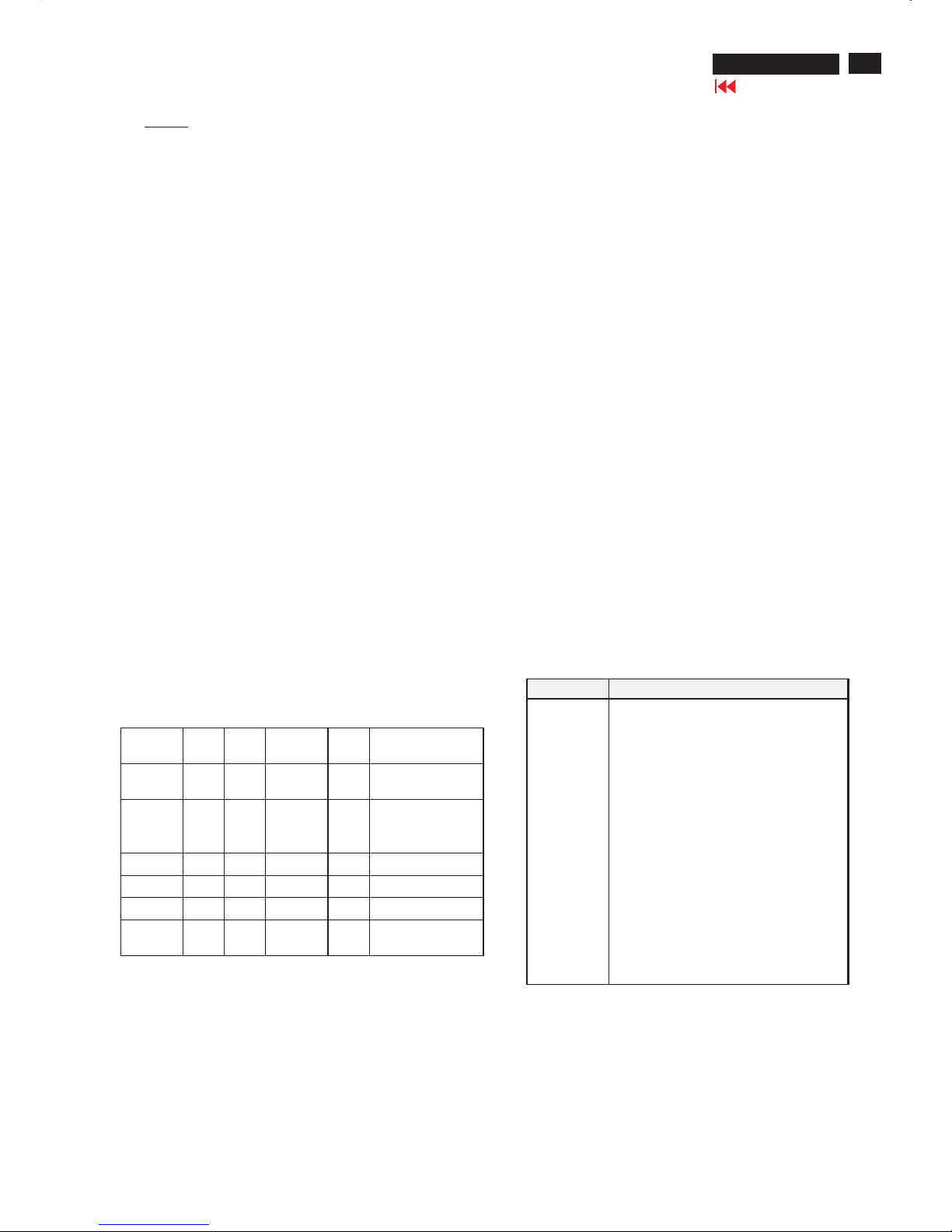
STATUS
H-
syncV-sync
Video
Powe
r
LED
On On On Active
<55WGreen /With Audio
andfull USB loading
On On On Active
<35
W
Green /Without
Audio andUSB
loading
Stand-by Off On Blanked<1W
Amber LED
SuspendOn Off Blanked<1W
Amber LED
Off Off Off Blanked<1WAmber LED
DC Power
off
N/A <1WLED Off
Note :
A. To achieve under 1 Watt power saving,make sure there is
no device load on USB downstream port(s).
B. To achieve under 1 Watt power saving when Stand-Alone Audio
feature isselectedOnand system is in Sleep Mode,follow
below twoconditions:
1.Volumehas to beadjuste
d to 0% prior to measurement.
2.Make sure there is no device load on USB downstream port(s).
1.2.3. Horizontal scan:30 -83KHz
1.2.4. Vertical scan:56 -76 Hz
"
"
"
"
1.2.5. Input signals
The input signals can be applied in two different modes:
1). VESA Analog
The video inputconsists of red, green, andblue signals. The video
signals are analog levels, where 0V corresponds to black and
700mV is the maximum signal amplitude.Inputimpedance o
f video
pins is75ohm+/-1%.
The capability ofsync signal inputsshall include separate sync,
composite sync andsync on green. inputimpedance:2k2ohms
The signals are defined asfollow:
Separate sync TTL level, Positive/Negative
Composite sync TTL level, Positive/Negative
Sync on green H-sync TTL level,
Positive/Negative
2).Intel DVI Digital
Input signal: Four channel TMDSsignals
Signal source: pattern generator format (Refer to the SPEC)
1.2.6 Audio
Amplifier and headphone section :
Outputpower:2x2Wrms into 16 Ohm
Input sensitivity: 500mVrms
Frequency range: 100Hz - 20KHz
Volum
econtrolkeypads are at the front control panel.
L/R inputvia1.8m hard-wired cable with limegreen3.5mm plug
Headphone connection will mute speakers.
Loudspeaker section :
Rated input 2.0W
Max. input 3.0W
Impedance 16 Ohm+/- 15%
Sensitivity76 dB +/-3 dB (at 1W/1m at 1KHz)
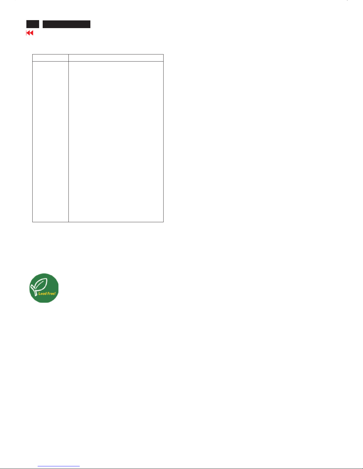
1.2.7 Input connectors
(1) I
nputanalogD-sub connector pin assignment
PIN No. SIGNAL
1 Red video input
2 Green video input /sync on green
3Bluevideo input
4 GND
5 GND
6 Red video GND
7 Green video GND
8Bluevideo GND
9DDC+3.3Vor +5V
10 Logic GND -Cable detect
11 GND
12Serial data line (SDA)
13H-sync /H+V
14V-sync
15 Data clock line (SCL)
4
190P6&170P6 LCD
Go to cover page
Technical Data(For 190P6)
(2) InputDVI-D connector pin assignment
Pin No. Description
1T.M.D.S. data2-
2 T.M.D.S. data2+
3 T.M.D.S. data2shield
4No Connect
5No Connect
6DDC clock
7 DDCdata
8No Connect
9T.M.D.S. data1-
10 T.M.D.S. data1+
11 T.M.D.S. data1 shield
12No Connect
13No Connect
14+5VPower
15Ground (for +5V) –Cable detect
16 Hot plug detect
17 T.M.D.S. data0-
18 T.M.D.S. data0+
19 T.M.D.S. data0 shield
20 No Connect
21 No Connect
22 T.M.D.S clockshield
23 T.M.D.S. clock+
24 T.M.D.S. clock-
Signal interface
15Pins, D-sub male with DDC-2B Pin assignments
24Pins, DVI-D male with DDC-2B Pin assignments
Sync polarity:
H-sync positive/negative
V-sync positive/negative
Lead-free Product
Philips elim inated toxic substances likeleadfrom itsdisplays.
Lead-free display helps protect your health andpromotes
environmentallysoun d recovery anddisposal ofwaste from
electrical and electronic equipment. Philips complieswith the
European Communitystringent R
oHS Directive mandating
restrictions on hazardous substances in electrical and electronic
equipment.With Philips, you can b econfid ent that your di splay
device does not harm the environment.
5
190P6&170P6 LCD
Go to cover page
Technical Data(For 170P6)
"
"
"
"
1. General
1.1.1Product description
170P6 is the 6th generation of Hudson 17 TFT Flat Panel Display
Monitor. The monitor featuredwith both DVI-Dand analog signal
input interface, andmodularized as a displayunit with embedded
universal AC power supplies inside monitor main body. The power
button anddispla
y control buttons (tact switch type) are on the front
of the monitor. The monitor shall support an internal scaler to
automatically enable the monitor to display lower resolution video
modes into 1280 x 1024 full screen display. The image can be
adjusted through OSDcontrolboard. Theseadjustments can be
store
d on a boardmemory including 34 pre-set modes and 16
factory pre-set modes.
1.1.2 Destination:AP, CN, EE, GB, LA, ME, SH, WE
1.2. Basic data
1.2.1 LCD panel
Type NR. : LM170E01-A6K3/A6K4 (LPL)
Number of Pixels. : 1280(H) x1024 (V)
Physical Size
. : 358.5(w)*296.5(h)*17.0(d) mm
Pixel Pitch.:0.264 (per one triad) x 0.264mm
Color pixel arrangement.:RGB vertical stripes
Support Color.:16.2M colors (RGB8bitsdata)
DisplayMode.:NormallyWhite
Backlight.:CCFL edge light system
Active area. (WXH).:337.92 x 270.336mm (17
diagonal)
Viewing Angle.:Vertical 140 degree,Horizontal
140 degree (CR=10)
Contrastratio.:500:1
White luminance.:250nits (Typ)
1.2.2. Power supply
Main Voltage:AC90 - 135 Vrms and 170-264Vrms, 50/60±2Hz
Power consumption:55wattsmax (full loading,with 4X USB
devices on down
stream ports, each device consumes 0.5 Amp)
Operating <35W(typical value; no device loading on USB
downstream port(s)) standby<1W.
DC power switch off < 1W (no device loading on USB
downstream port(s))
Power cord length: 1.5M
Power cord type:3leadwith earth plug
Power indicator:LED(ON: green,S
tandby: amber)
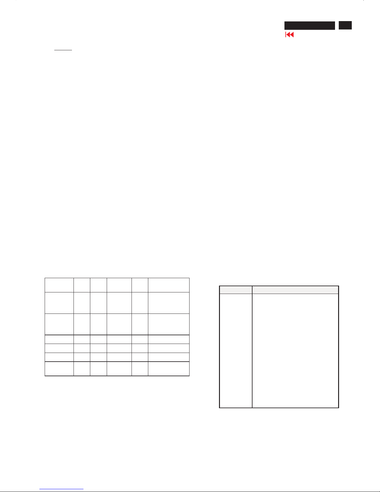
Auto power saving:EPA, Nutek, VESA, DPMS,
STATUS
H-
syncV-sync
Video
Powe
r
LED
On On On Active
<55
W
Green /With Audio
andfull USB
loading
On On On Active
<35
W
Green /Without
Audio andUSB
loading
Stand-by Off On Blanked<1W
Amber LED
SuspendOn Off Blanked<1W
Amber LED
Off Off Off Blanked<1WAmber LED
DC Power
off
N/A <1WLED Off
Note :
A. To achieve under 1 Watt power saving,make sure there is no
device load on USB downstream port(s).
B. To achieve under 1 Watt power saving when Stand-Alone
Audio feature isselectedOnand system is in Sleep Mode,
followbelow twoconditions:
1.Volumehas to beadjusted to 0% prior to measurement.
2.Make sure there is no device load on USB downstream port(s).
1.2.3.Horizontal scan:30 -83KHz
1.2.4.Vertical scan:56 - 76 Hz
1.2.5. Input signals
The input signals can be applied in two different modes:
1). VESA Analog
The video inputconsists of red, green, andblue signals. The video
signals are analog levels, where 0V corresponds to black and 700mV
is the maximum signal amplitude.Inputimpedance of
video pins is
75 ohm+/-1%.
The capability ofsync signal inputsshall include separate sync,
composite sync andsync on green. inputimpedance:2k2ohms
The signals are defined asfollow:
Separate sync TTL level, Positive/Negative
Composite sync TTL level, Positive/Negative
Sync on green H-sync TTL level,
Positive/Negative
2).Intel DVI Digital
Input signal: Four channel TMDSsignals
Signal source: pattern generator format (Refer to the SPEC)
1.2.6 Audio
Amplifier and headphone section :
Outputpower:2x2Wrms into 16 Ohm
Input sensitivity: 500mVrms
Frequency range: 100Hz - 20KHz
Volum
e control keypads are at the front control panel.
L/R inputvia1.8m hard-wired cable with limegreen3.5mm plug
Headphone connection will mute speakers.
Loudspeaker section :
Rated input 2.0W
Max. input 3.0W
Impedance 16 Ohm+/- 15%
Sensitivity 76 dB +/-3 dB (at 1W/1m at 1KHz)
1.2.7 Input connectors
(1) InputanalogD-sub connector pin assignment
PIN No. SIGNAL
1 Red video input
2 Green video input /sync on green
3Bluevideo input
4 GND
5 GND
6 Red video GND
7Greenvideo GND
8Bluevideo GND
9 DDC +3.3V or +5V
10 Logic GND -Cable detect
11 GND
12Serial data line (SDA)
13H-sync /H+V
14V-sync
15 Data clock line (SCL)

6
190P6&170P6 LCD
Go to cover page
Technical Data(For 170P6)
Lead-free Product
Philips elim inated toxic substances likeleadfrom itsdisplays.
Lead-free display helps protect your health andpromotes
environmentallysoun d recovery anddisposal ofwaste from
electrical and electronic equipment. Philips complieswith the
European Communitystringent R
oHS Directive mandating
restrictions on hazardous substances in electrical and electronic
equipment.With Philips, you can b econfid ent that your di splay
device does not harm the environment.
(2) InputDVI-D connector pin assignment
Pin No. Description
1T.M.D.S. data2-
2 T.M.D.S. data2+
3 T.M.D.S. data2shield
4No Connect
5No Connect
6DDC clock
7DDCdata
8No Connect
9 T.M.D.S. data1-
10 T.M.D.S. data1+
11 T.M.D.S. data1 shield
12No Connect
13No Connect
14+5VPower
15Ground (for +5V) –Cable detect
16 Hot plug detect
17 T.M.D.S. data0-
18 T.M.D.S. data0+
19 T.M.D.S. data0 shield
20 No Connect
21 No Connect
22 T.M.D.S clockshield
23 T.M.D.S. clock+
24 T.M.D.S. clock-
Signal interface
15Pins, D-sub male with DDC-2B Pin assignments
24Pins, DVI-D male with DDC-2B Pin assignments
Sync polarity:
H-sync positive/negative
V-sync positive/negative
7
190P6&170P6 LCD
Go to cover page
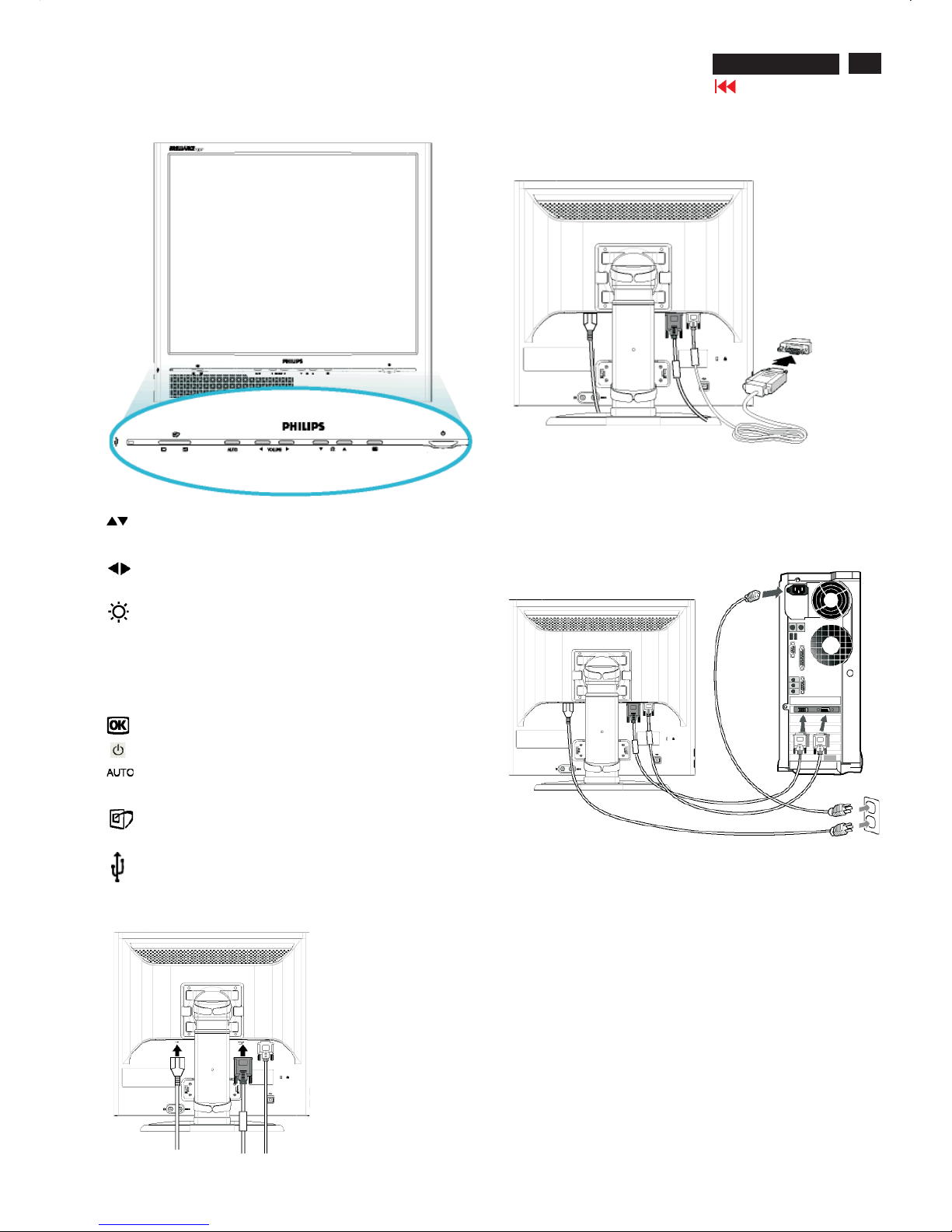
Connection to PC
Front view
UPandDOWNbuttons are used when adjusting the OSD ofyour
monitor.
LEFT andRIGHT buttons, likethe UPandDOWNbuttons, are
also used in adjusting the OSD ofyour monitor.
BRIGHTNESS hotkey. W hen the UPandDOWNarrow
buttons are pressed, theadjustment controls for the BRIGHTNESS
wi
ll show up.
VOLUME hotkey. W hen the LEFT andRIGHT arrow buttons are
pressed, theadjustment controls for VOLUME will show up.
OK button which when pressed will take you to the OSD controls
POWER button switchesyour monitor on.
Automatically adjustthe horizontal pos
ition, vertical position,
phaseand clocksetting.
LightFrame
TM
hotkeyfor mode-switching between full-screen mode
andmulti-window mode.
USB Hub for versatileperipheral connections
VOLUME
Connecting to PC
1) Pluginthecables into connectors
Note: If youuseanApple Macintosh, you need to connect the
specialMac adapter to one end of the monitor signal cable
(2) Connect to PC
(a) Turn off yourcomputer andunplugits power cable.
(b) Connect the monitor signal cabletothevideo connector on the
back ofyourcomputer.
(c) Plugthe power cord ofyourcomputer andyour monitor into a
nearby outlet.
(d) Turn on yourcomputer andmonitor.If
the monitor displays an
image, installation is complete.

8
190P6&170P6 LCD
Go to cover page
On Screen Display
On-Screen Display (OSD) is a feature in all Philips LCD monitors.Itallowsanenduser to adjust screen performance or selectfunctions
of the monitors directly through an on-screen instruction window. A user friendly on screen display interface is shownasbelow :
In theOSDshownleft users can press buttons
atthe frontbezel of the monitor to move thecursor,
to
confirmthechoice orchange, and
to adjust/selectthechange.
OSD Tree

9
190P6&170P6 LCD
Go to cover page
Front Control Panel
To Lock/Unlock OSD FUNCTION(User Mode)
The OSD function can be locked by pressing"OK"button(1) for more
than 10 seconds, the screen shows following windows for 3 seconds.
Everytime when you press"AUTO" or "OK" button, this message appears on the screen automatically.
ATTENTION SIGNAL
OSD MAIN CONTROLS UNLOCKED
Unlock OSD function
Locked OSD function can be released by pressing "OK" button for more
than 10 seconds again
ATTENTION SIGNAL
OSD MAIN CONTROLS LOCKED
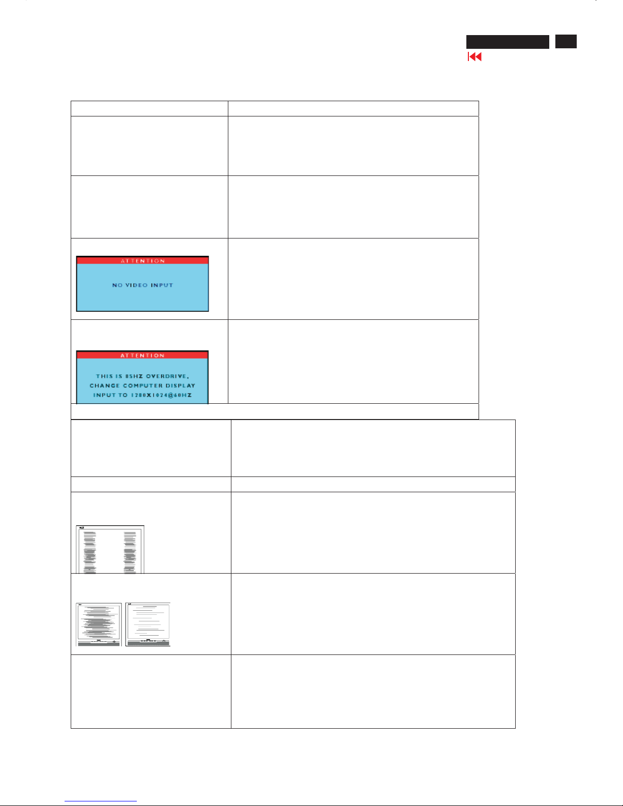
NO VIDEO INPUT
This screen appears if there is no video signal input. Please check that
the signal is properly connected to the video card of PC and make sure
PC is on
ATTENTION SIGNAL
CHECK CABLE CONNECTION
CANNOT DISPLAY THIS VIDEO MODE..
This screen warns when the input frequency from the computer is not
a standard video mode or out of the monitor's scanning range.
Please change the display mode of the operating software in the computer(i.e.windows) to 1280*1024@60HZ for best display results.
ATTENTION SIGNAL
CANNOT DISPLAY THIS VIDEO
MODE,CHANGE COMPUTER DISPLAY
I
N
P
U
T
TO
1
2
8
0
*
1
0
2
4
@
6
0
H
Z
I
WAIT FOR AUTOMATIC ADJUSTMENT
This screen appears when you press the "AUTO" buttons at the same
time. It will disappear when the monitor is properly adjusted
ATTENTION SIGNAL
WAITING FOR AUTOMATIC ADJUSTMENT
Access Aging.. Mode
Step 1 : Turn off LCD monitor, and disconnect Interface Cable
between Monitor and PC.
Step 2 : [Push AUTO " " & " " buttons at the same time and
hold it]+[Press power " " button until comes out " AGING screen"
] => then release all buttons.
Bring up:
AGING...
After 15 seconds, bring up:
After 15 seconds, bring up:
AGING...
After 15 seconds, bring up:
----------
---------repeatly
Connect Signal cable again=> go back to normal display
OSD Lock/Unlock, Aging Mode
10
190P6&170P6 LCD
Go to cover page
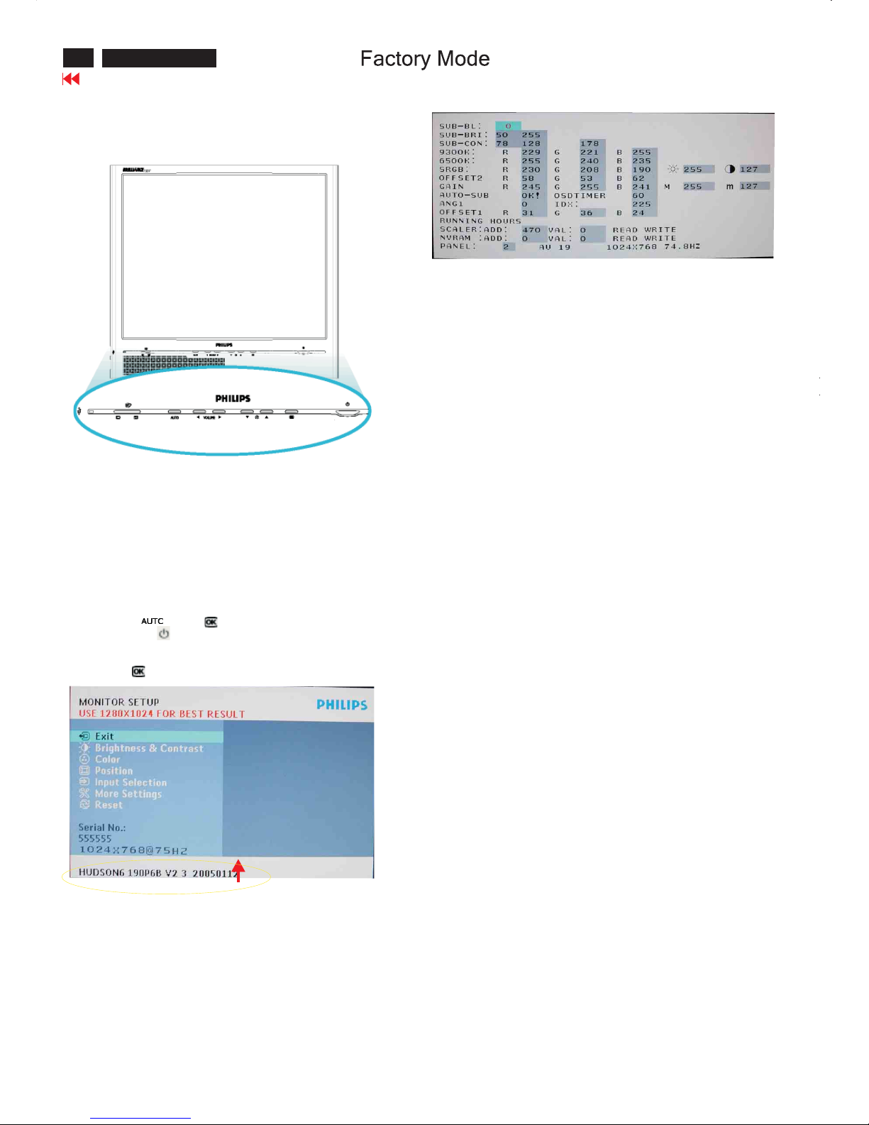
Front Control Panel
Access Factory Mode
How to get into Factory Mode Menu
Step1:
Turn off monitor.
Step2:
[Push AUTO " " & OK " " buttons at the same time and hold it]
+[Press power " " button untill comes out "Windows screen" ]
=> then release all buttons
Step3:
Press OK " " button, bring up Factory mode indication as shown
in Fig2.
Factory Mode indicator
Factory Menu
Cursor can move on gray color area
Hot key function: by pressing " up " and " DOWN " key
Simultaneously at User Mode (or Factory Mode)
(PS:TheOffsetRGBfunction can be used on reduce or eliminate
snowy noise on the background when the resolution of video signal
is 1280*1024 vertical 60Hz. Slightly increase or decrease the value
until snowy noise completely disappear
BL : Blacklevel value
SUB-BRI : Brightness value range(Min Max)
SUB-CON : Contrast value range(Min Mid Max)
SRGB-B : Brightness of sRGB
SRGB-C:ContrastofsRGB
Gain-m : Minimum value of User Gain
Gain-M:Maximum value of User Gain
AUTO-SUB: To do Auto color function when push Menu key in white
pattern
OSDTIMER : OSD time out control(sec)
ANG1 : For analog only project control (0:Dual, 1:Analog only)
IDX : Limit current of inverter
SCALER:Read/Write scaler register
NVRAM : Read/Write eeprom address
Panel : LG(LG.Philips panel)
11
190P6&170P6 LCD
Go to cover page
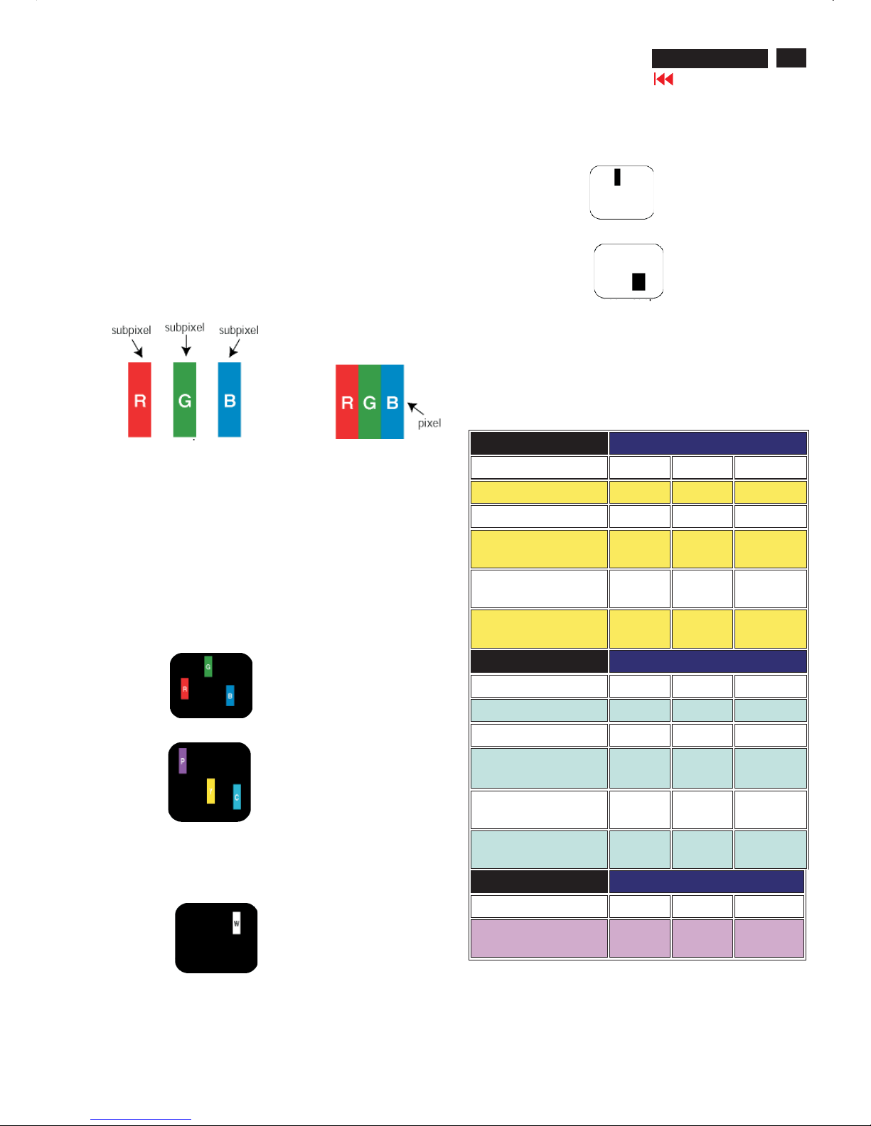
Philips' Flat Panel Monitors Pixel Defect Policy
Pixels and Subpixels
Types of Pixel Defects
Philips strives to deliver the highest quality products. We use some of
the industry's most advanced manufacturing processes and practice
stringent quality control. However, pixel or subpixel defects on the TFT
LCD panels used in flat panel monitors are sometimes unavoidable.
No manufacturer can guarantee that all panels will be free from pixel
defects, but Philips guarantees that any monitor with an unacceptable
number of defects will be repaired or replaced under warranty.
This notice explains the different types of pixel defects and defines
acceptable defect levels for each type. In order to qualify for repair or
replacement under warranty, the number of pixel defects on a TFT LCD
panel must exceed these acceptable levels.
For example, no more than 0.0004% of the subpixels on a 15" XGA
monitor may be defective. Furthermore, Philips sets even higher quality
standards for certain types or combinations of pixel defects that are
more noticeable than others. This policy is valid worldwide .
A pixel, or picture element, is composed of three subpixels in the
primary colors of red, green and blue. Many pixels together form an
image. When all subpixels of a pixel are lit, the three colored subpixels
together appear as a single white pixel. When all are dark, the three
colored subpixels together appear as a single black pixel.
Other combinations of lit and dark subpixels appear as single pixels of
other colors.
Pixel and subpixel defects appear on the screen in different ways.
There are two categories of pixel defects and several types of subpixel
defects within each category.
Bright Dot Defects Bright dot defects appear as pixels or subpixels that
are always lit or "on".
These are the types of bright dot defects:
One lit red, green or blue subpixel
Two adjacent lit subpixels:
-Red+Blue=Purple
-Red+Green=Yellow
- Green + Blue = Cyan (Light Blue)
Three adjacent lit subpixels
(one white pixel)
Black Dot Defects
Proximity of Pixel Defects
Pixel Defect Tolerances
Black dot defects appear as pixels or subpixels that are always dark or
"off".
These are the types of black dot defects:
One dark subpixel
Two or three adjacent dark subpixels
Because pixel and subpixels defects of the same type that are nearby
one another may be more noticeable, Philips also specifies tolerances
for the proximity of pixel defects.
In order to qualify for repair or replacement due to pixel defects during
the warranty period, a TFT LCD panel in a Philips flat panel monitor
must have pixel or subpixel defects exceeding the tolerances listed in
the following tables.
BRIGHT DOT DEFECTS ACCEPTABLE LEVEL
MODEL
190P6 190B6 190S6
1 lit subpixel 0 0 3 or fewer
2 adjacent lit subpixels 0 0 1 or fewer
3 adjacent lit subpixels (one
white pixel)
0 0 0
Distance between two bright
dot defects*
00
25 mm or
more
Total bright dot defects of all
types
0 0 3 or fewer
BLACK DOT DEFECTS ACCEPTABLE LEVEL
MODEL
190P6 190B6 190S6
1 dark subpixel 0 0 5 or fewer
2 adjacent dark subpixels 0 0 2 or fewer
3 adjacent dark subpixels 0 0 0
Distance between two black
dot defects*
00
15 mm or
more
Total black dot defects of all
types
0 0 5 or fewer
TOTAL DOT DEFECTS ACCEPTABLE LEVEL
MODEL
190P6 190B6 190S6
Total bright or black dot
defects of all types
0 0 5 or fewer
Pixel Defect Policy
12
190P6&170P6 LCD
Go to cover page
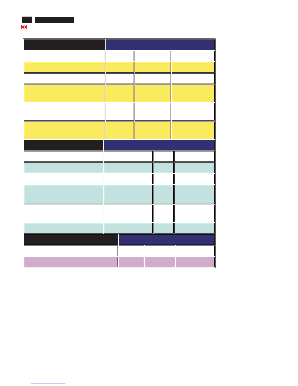
Pixel Defect Policy
BRIGHT DOT DEFECTS ACCEPTABLE LEVEL
MODEL
170P6 170B6 170S6
1 lit subpixel 0 0 4 or fewer
2 adjacent lit subpixels 0 0 2 or fewer
3 adjacent lit subpixels (one white
pixel)
0 0 0
Distance between two bright dot
defects*
0 0 15 mm or more
Total bright dot defects of all types 0 0 4 or fewer
BLACK DOT DEFECTS ACCEPTABLE LEVEL
MODEL
170P6 170B6 170S6
1 dark subpixel 0 0 4 or fewer
2 adjacent dark subpixels 0 0 2 or fewer
3 adjacent dark subpixels 0 0 0
Distance between two black dot
defects*
0 0 15 mm or more
Total black dot defects of all types 0 0 4 or fewer
TOTAL DOT DEFECTS ACCEPTABLE LEVEL
MODEL
170P6 170B6 170S6
Total bright or black dot defects of all types 0 0 5 or fewer
13
190P6&170P6 LCD
Go to cover page
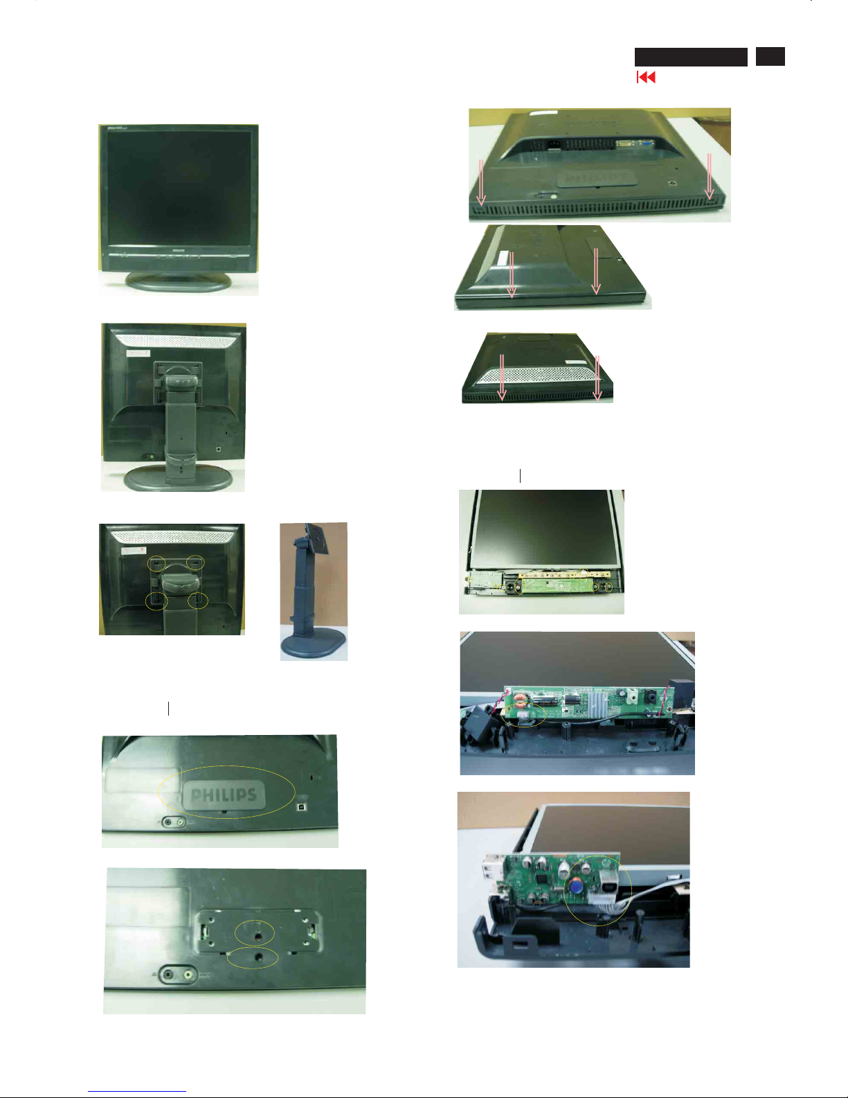
Front View
Back View
Step1. Remove the base
-Remove the screws as shown in Fig.3 & Fig.4
Step2. Remove the Front Bezel
-Open the cover and remove the one screw as shown in Fig.5, Fig.6
-Use the thin " " screw driver to open the clicks as shown
in Fig.7-9
Step3.Remove the Back cover
- Remove the screws and disconnect the connectors as shown in Fig.10 ,
Fig.11 Fig.12,Fig.13 then remove the AUDIO board, USB board and
control board
-Use the thin " " type screw driver to open the clicks as shown in Fig.10
Fig.4
Fig.5
F
i
g
9
Fig.10
Fig.11
Fig.3
F
i
g
.
8
F
i
g
.
7
Fig.6
Fig.12
Mechanical Instructions
14
190P6&170P6 LCD
Go to cover page
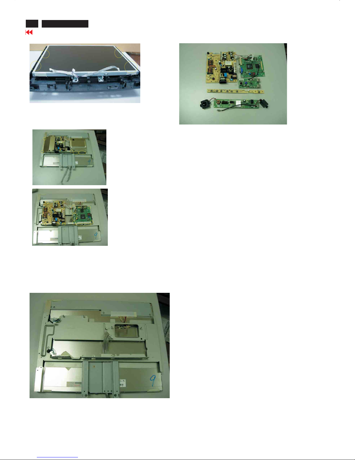
Step 5. Remove the scaler and power board.
- Disconnect the connectors and remove unscrew the screws as shown
in Fig.15
- Remove the scaler and power board as shown in Fig.16 Fig.17
**************************************************************************************
***************************************************************************************
In warranty, it is not allowed to disassembly the LCD panel, even the
backlight unit defect.
Out of warranty, the replacement of backlight units is a correct way
when the defect is caused by backlight (CCFL, Lamp).
Fig.17
Fig.13
Fig.16
Step4. Remove the Matel frame board
- Remove the screws and then remove the metal frame
as shown in Fig.15 Fig.14
Fig.14
Fig.15
Mechanical Instruction
15
190P6&170P6 LCD
Go to cover page
Alignment procedure
1. Turn on the LCD monitor.
2.Turn on the Timing/pattern generator. See Fig.1
Resolution :1280x1024(Use the best resolution)
Timing : H= 31.47KHz V=60Hz
3. Preset LCD color Analyzer CA-110
-Remove the lens protective cover of probe CA-A30.
-Set measuring/viewing selector to measuring position for reset
analyzer.(zero calibration) as Fig.2
- Turn on the color analyzer (CA-110)
-Press 0-CAL button to starting reset analyzer. See Fig.3
Fig. 1
Fig. 2
Cover (black)Cover (black)
Measurement viewing selectorMeasurement viewing selector
Note: after alignment, please reset OSD to user s mode for normal
operation. Otherwise, the monitor won t entering power saving mode
and showing full white picture all the time as no video signal supplied.
To leave factory mode by restart the monitor.
5.Adjust OSD menu to lower position of screen (i.g. adjust V-position to
value " 0 " at submenu of OSD Setting.
6. Setting Brightness and Contrast
-Adjust Brightness to value "90".
-Adjust Contrast to value " 80" .
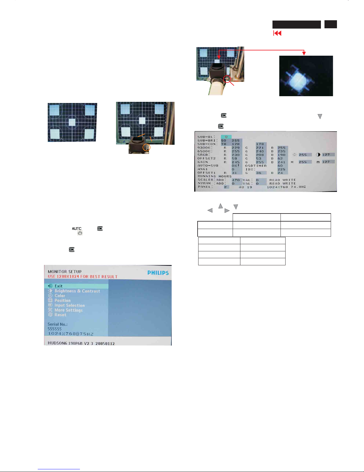
7. Switch light probe to Viewing position.
8. Move the Lens barrel forward or backward to get clear image as
showninFig.4
9. Switch light probe to Measuring position. It should be able to indicate
Clear imageClear image
Measurement/viewing selectorMeasurement/viewing selector
Alignment hits: 1. R for x value, G for y value,Bfor Y value on the
colour analyzer.
2. If the colour analyzer has been calibrated and preset
colour temperature in it. Please switch to correct
setting in accordance with colour settings.
4. Access Factory Mode
How to get into Factory Mode Menu
Step1:
Turn off monitor.
Step2:
[Push AUTO" "& OK ""buttons at the same time and hold it]
+[Press power ""button untill comes out "Windows screen" ]
=> then release all buttons
Step3:
Press OK ""button, bring up Factory mode indication as shown
in Fig3.
Fig. 3
10. Setting pattern to full white picture
11. Press button, then select factory mode indicator by"" ""
button
12. Press""button to bring up submenu windows as below:
13. Press ""or ""button to select R G B. Change the value by
""or ""key until the X,Y co-ordinates as below
Fig.4
15. EEPROMpresetting(B)
After finishing all the adjustment, set:
Brightness control to 100%
Contrast control to 50%
OSD position at middle of screen
COLORadjusts to 6500K color.
9300°K6500°K
x (center) 0.283 ± 0.020 0.313 ± 0.020
y(center) 0.297 ± 0.020 0.329 ± 0.020
sRGB
x(center) 0.313 ± 0.020
y(center) 0.329 ± 0.020
Ynits 180 ± 10
Display Adjustment
16
190P6&170P6 LCD
Go to cover page
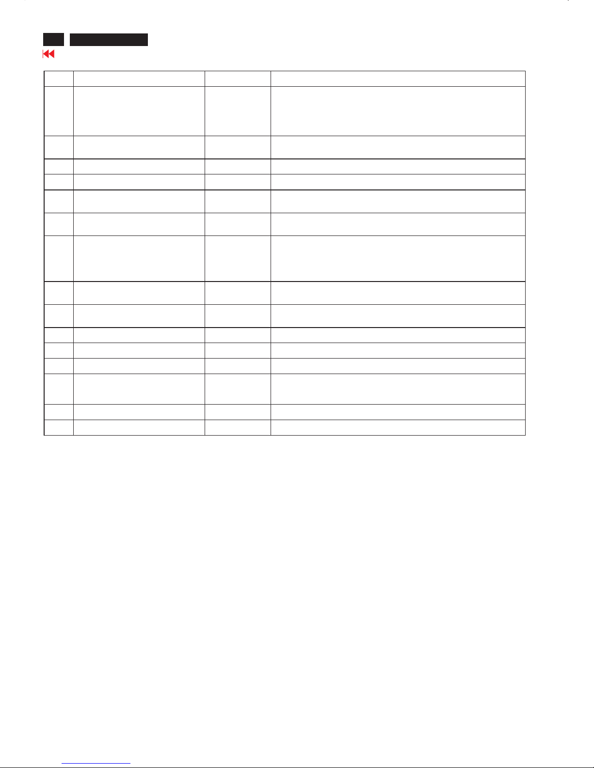
Warning Message Table
Item Attention Signals Display Time Condition
1 CANNOT DISPLAY THIS VIDEO MODE,
CHANGE COMPUTER DISPLAY INPUT
TO 1280X1024 @60Hz
30 mins This warning appears when the input signal from your computer is not in a standard
video mode or is out of the monit or s scanning range. After 30 mins, monitor enters
sleeping mode.
2 NO VIDEO INPUT 30mins This message appears when there is no signal input but with cable while AC or DC
power on. After 30 mins, monitor enters sleeping mode
3 CHECK CABLE CONNECTION 30mins This message appears when a signal cable is disconnected while monitor is working,
after 30 mins, monitor enters sleeping mode
4 ENTERING SLEEP MODE 3 secs This message appears when monitor is about to enter power saving mode
5 WAITING FOR AUTOMATIC
ADJUSTMENT
Till auto adjustment
finished
This message displayed when the auto adjustment button is pressed. It dis appears
when automatic adjustments are completed
6 USE 1280X1024 FOR BEST RESULT On top of OSD
main menu
The message will show up at the top of the OSD main menu in red color when the input
resolution is not the 1280x1024.
7 OSD MAIN CONTROLS LOCKED 3 secs / or Till
OSD MAIN
CONTROLS
UNLOCKED
appear
This message will appear 3 seconds to indicate the OSD MAIN CONTROLS status
when to lock or un-lock it by pressing MENU(OK) button for more than 10 seconds
while there is video input from PC. This function provides the alternative that user can
lock all the OSD main control in case user don t want the FOS performance setting to
be changed, for ins tance, during
Commercial exhibition
8 OSD MAIN CONTROLS UNLOCKED 3 secs This message will appear 3 seconds to indicate the OSD MAIN CONTROLS status
when to un-lock it by pressing MENU(OK) button for more than 10 seconds while
there is video input from PC
9 THIS IS 85HZ OVERSCAN, CHANGE
COMPUTER DISPLAY INPUT TO
1280X1024@60HZ
10 mins This message will appear 5 seconds in every 60 seconds for 10 minutes when the input
of PC video timing is at 85Hz mode. Remark: AUTO is still functional in this mode
10 the window of " MONITOR SETUP" 60 secs This message will appear when the OK button is pressed.
11 the window of "BRIGHTNESS" 60 secs This message will appear when the BRIGHTNESS button is pressed.
12 SELECTED INPUT NOT AVAILABLE 3 secs When just one input (analog or digital), press input switch or hot key, then after
show this warning message 3 sec, return to origi nal input
13 SECURITY PROTECTED, THIS
MONITOR IS GO ING TO ENTER POWER
SAVING MODE IN 15 SECONDS
15 secs This warning appears when the security was set ON and someone
takes out from the cli ent PC
14 ENTER POWER SAVING MODE 1 min This warning appears when Asset management Server sends power saving command
to client PC
15 the window of VOLUME 60 secs This message will appear when the VOLUME button is pressed.
"
"
"
"
""
""
""
""
""
'
17
190P6&170P6 LCD
Go to cover page
Trouble shooting
CommonProblems
Display positionisincorrect
· Press the Auto button.
· Adjustthe image positionusingthe HorizontalPosition and/or Vertical
PositioninOSDMain Controls.
Image vibrates on the screenCheck that the signal cable is properly connected to thegraphicsboard or PC.
Verticalflicker appears
· Press the Auto button.
· Eliminate theverticalbarsusingthe More Settings ofPhase/Clockin
OSD Main Controls.
Horizontalflicker appears
· Press the Auto button.
· Eliminate theverticalbarsusingthe More Settings ofPhase/Clockin
OSD Main Controls.
The screenistoo brightortoodark
· Adjustthecontrastand brightness onOSDMain Controls. (The
backlightof the LCD monitor has a fixedlife span. When the screen
becomesdark or begins to flicker, pleasecontact your dealer).
Havingthis problem Check these items
No Picture
(Power LED not lit)
· Make sure thepower cordispluggedinto thepower outlet
and into the back of the monitor.
· First, ensure that thepower button on the frontof the monitor
is in the OFF position, then press ittothe ON position.
No Picture
(Power LED is amber or yellow)
· Make sure thecomputer is turned on.
· Make sure the signal cable is properly connected to your
computer.
· Check to see if the monitor cable hasbentpins.
Screen
· Make sure the monitor cable is properly connected to your
computer.(Alsorefer to the QuickSet-UpGuide).
· Check to see if the monitor cable hasbentpins.
· Make sure thecomputer is turned on.
Screensays
· Make sure theverticalsyncofinput signaliswithin therange
of56~75Hz.
· Change therefresh rate to 56~75Hz within10minutes.
· Re-power onmonitor to start over again if youfailed to
change therefresh rate within 10 minutes.
Imaging Problems

18
190P6&170P6 LCD
Go to cover page
Trouble shooting
An after-image appears
· If an image remains on the screen for an extended period of time, it
may be imprinted in the screen and leave an after-image. This usually
disappears after a few hours
An after-image remains after the power has
been turned off.
· This is characteristic of liquid crystal and is not caused by a
malfunction or deterioration of the liquid crystal. The after-image will
disappear after a peroid of time.
Green, red, blue, dark, and white dots
remains
The remaining dots are normal characteristic of the liquid crystal used in today’s
technology
19
190P6&170P6 LCD
Go to cover page
Electrical instructions(190P6)
20
190P6&170P6 LCD
Go to cover page
Electrical instructions(190P6)
4.3 Adjustment of WHITE-D (B)
Apply a 1280*1024 / 60Hz signal with white pattern, set brightness
to 100%, and contrast to 50%. Adjust the R, G, B Sub-Gain, for the
screen center, the 1931 CIE chromaticity (X, Y) co-ordinates shall
be;
Use Minolta CA-110 for color coordinates and luminance check.
Luminance is > 200 Nits in the center of the screen when
brightness is set to 100% and contrast is set to 50%.
4.4 Adjustment of sRGB
Apply a 1280*1024 / 60Hz signal with white pattern, set brightness
to 100%, and contrast to 50%. Adjust the R, G, B Sub-Gain,
for the screen center, the 1931 CIE chromaticity
(X, Y) co-ordinates shall be;
sRGB
x(center) 0.313 ± 0.020
y(center) 0.329 ± 0.020
Ynits 180 ± 10
4.5 EEPROM presetting (B)
After finishing all the adjustment, set:
Brightness to 100%
Contrast to 50%
OSD position at middle of screen
COLOR ADJUST to 6500K color temperature.
Stand-Alone set to Off
Smart Bright set to Off
9300°K 6500°K
x (center) 0.283 ± 0.020 0.313 ± 0.020
y (center) 0.297 ± 0.020 0.329 ± 0.020

21
190P6&170P6 LCD
Go to cover page
Electrical instructions(170P6)
1. General points
1.1 During thetestandmeasuring, supply a distortion free AC mains
voltagetothe apparatus via an isolated transformer with low
internal resistance.
1.2 All measurements mentionedhereafter are carried out at a normal
mains voltage (90 - 132 VAC for USA version, 195 -264VACfor
EUROPEAN version, or 90 -264 VAC for the model withfull range
power supply, unless otherwise stated.
)
1.3 All voltages are to be measured or appliedwith respect to ground,
unless otherwise stated.
Note:do not use heat-sink as ground.
1.4 Thetesthas to be done on a complete set including LCD panel
after 30 minutes warm-up at least in a roomwith temperature of
25 +/- 5 degree C.
1.5 All values mentioned in these test instruction are only applicable of
a well aligned apparatus,with correct signal.
1.6 Theletterssymbols (B)an
d (S)placedbehind the test instruction
denotes
(B): carried out 100% inspection at assembly line
(S): carried out test by sampling
1.7 The white balance (color temperature) has to betested in subdued
lighted room.
1.8 Repetitive power on / off cycle are allowed except it shouldbe
avoidedwithin6sec.
2. Input signal
2.1 Signal type
2.1.1 Video signal input
Signal source: pattern generator format (refer to spec)
Reference generator:QuantumData 802G
The input signals can be applied in two different modes:
1).VESA Analog
Thevideo input consists of red, green, andblue signals.Thevideo
signals are analog levels,where 0V correspondstoblack and 700mV
is the maximum signal amplitude.Input impe
dance of video pins is
75 ohm +/- 1%.
2).Intel DVI Digital
Input signal:Four channel TMDS signals
2.1.2 Sync signal input
Thecapability of sync signal inputs shall include separate sync,
composite sync and sync on green. input impedance:2k2ohms
The signals are defined as follow:
Separate sync TTL level, Positive/Negative
Composite sync TTL level, Positive/Negative
Sync on green
H-sync TTL level, Positive/Negative
Signal source: pattern generator format (refer to spec)
Reference generator:QuantumData 802G
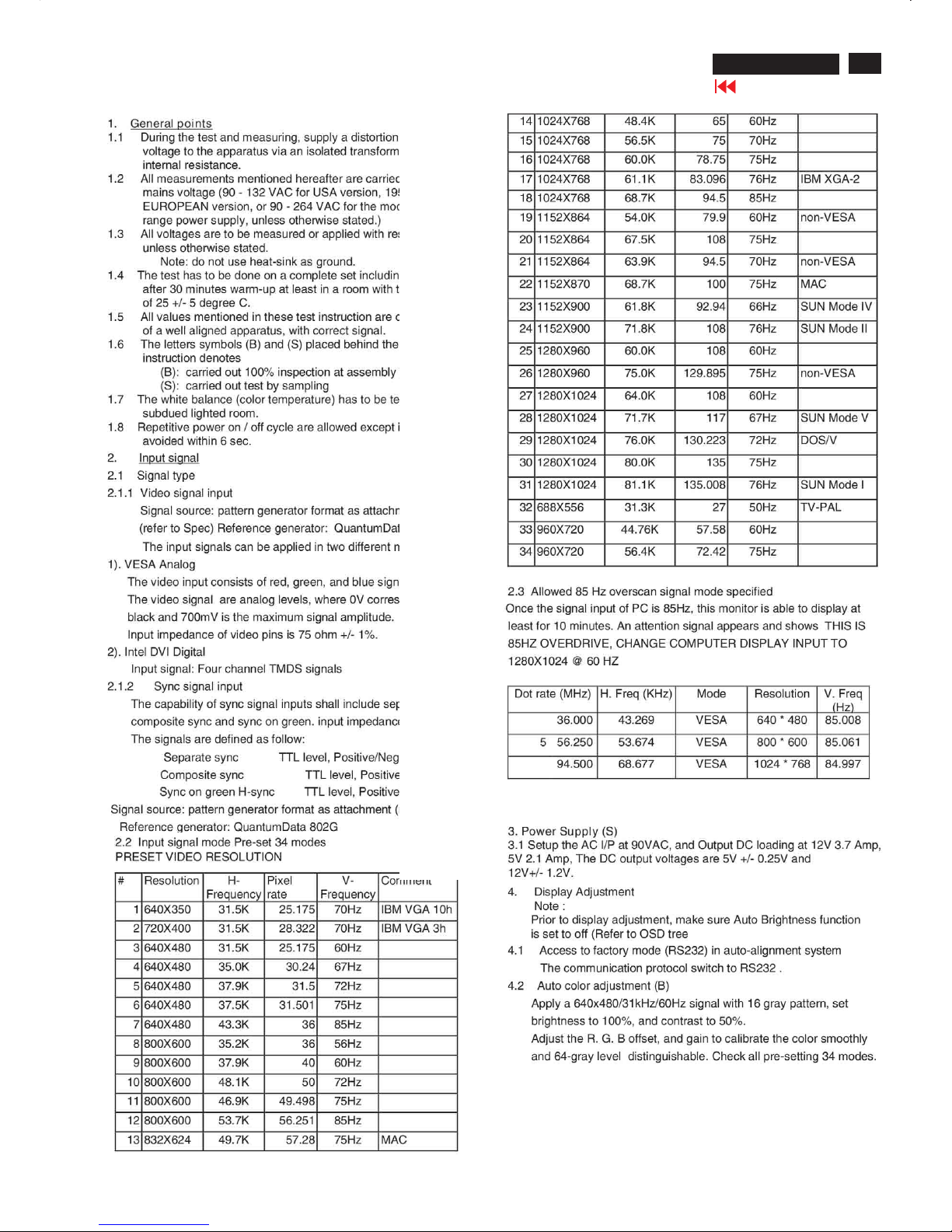
2.2 Input signal mode
Pre-set 34 modes
PRESETVIDEORESOLUTION
#Resolution H-
Frequency
Pixel
rate
V-
Frequency
Comment
1640X350 31.5K 25.175 70Hz IBM VGA 10h
2 720X400 31.5K 28.322 70Hz IBM VGA3h
3 640X480 31.5K 25.175 60Hz
4 640X480 35.0K30.24 67Hz
5 640X480 37.9K 31.5 72Hz
6640X480 37.5K 31.501 75Hz
7640X480 43.3K 36 85Hz
8800X600 35.2K 36 56Hz
9800X600 37.9K 4060Hz
10 800X600 48.1K5072Hz
11 800X600 46.9K 49.498 75Hz
12800X600 53.7K56.251 85Hz
13 832X624 49.7K57.28 75Hz MAC
14 1024X768 48.4K 65 60Hz
15 1024X76856.5K 75 70Hz
16 1024X768 60.0K 78.75 75Hz
17 1024X768 61.1K 83.09676Hz IBM XGA-2
18 1024X768 68.7K 94.5 85Hz
19 1152X864 54.0K 79.9 60Hz non-VESA
201152X864 67.5K 108 75Hz
211152X864 63.9K 94.5 70Hz non-VESA
22 1152X870 68.7K 100 75Hz MAC
23 1152X900 61.8K 92.94 66Hz SUN Mode IV
24 1152X900 71.8K 108 76Hz SUN Mode II
25 1280X960 60.0K 108 60Hz
261280X960 75.0K 129.89575Hz non-VESA
271280X1024 64.0K 108 60Hz
28 1280X1024 71.7K 117 67Hz SUN Mode V
29 1280X1024 76.0K 130.22372Hz DOS/V
301280X1024 80.0K 135 75Hz
311280X1024 81.1K 135.00876Hz SUN Mode I
32 688X556 31.3K 27 50Hz TV-PAL
33 960X720 44.76K57.58 60Hz
34 960X720 56.4K 72.42 75Hz
2.3 Allowed85Hzoverscan signal mode specified
Once the signal input of PC is 85Hz, this monitor is able to display at
least for10 minutes.An attention signal appears and shows THIS
IS 85HZ OVERDRIVE, CHANGE COMPUTERDISPLAY INPUT TO
1280X1024 @ 60 HZ
Dot rate (MHz) H.
Freq (KHz)
Mode Resolution V.
Freq (Hz)
36.000 43.269VESA 640 *480 85.008
556.250 53.674VESA 800 * 600 85.061
94.500 68.677 VESA 1024 * 768 84.997
3. Power Supply (S)
3.1 Setup the AC I/Pat90VAC, andOutput DC loading at 12V 3.7 Amp,
5V 2.1 Amp,The DC output voltages are 5V +/- 0.25V and 12V+/- 1.2V.
22
190P6&170P6 LCD
Go to cover page
Electrical instructions(170P6)
4. Display Adjustment
Note :
Prior to display adjustment, make sure Auto Brightness function
is set to off (Refer to OSD tree)
4.1 Access to factory mode (RS232) in auto-alignment system
The communication protocol switch to RS232 .
4.2 Auto color adjustment (B)
Apply a 640x480/31kHz/60Hz signal with 16 gray pattern,
set brightness to 100%, and contrast to 50%.
Adjust the R. G. B offset, and gain to calibrate the color
smoothly and 64-gray level distinguishable.
Check all pre-setting 34 modes.
4.3 Adjustment of WHITE-D (B)
Apply a 1280*1024 / 60Hz signal with white pattern, set
brightness to 100%, and contrast to 50%. Adjust the
R, G, B Sub-Gain, for the screen center, the 1931 CIE
chromaticity (X, Y) co-ordinates shall be;
Use Minolta CA-110 for color coordinates and luminance check.
Luminance is > 200 Nits in the center of the screen when
brightness is set to 100% and contrast is set to 50%.
4.4 Adjustment of sRGB
Apply a 1280*1024 / 60Hz signal with white pattern, set brightness
to 100%, and contrast to 50%. Adjust the R, G, B Sub-Gain, for
the screen center, the 1931 CIE
chromaticity (X, Y) co-ordinates shall be;
sRGB
x(center) 0.313 ± 0.020
y(center) 0.329 ± 0.020
Ynits 180 ± 10
4.5 EEPROM presetting (B)
After finishing all the adjustment, set:
Brightness to 100%
Contrast to 50%
OSD position at middle of screen
COLOR ADJUST to 6500K color temperature
Stand-Alone set to Off
Smart Bright set to Off
9300°K 6500°K
x (center) 0.283 ± 0.020 0.313 ± 0.020
y (center) 0.297 ± 0.020 0.329 ± 0.020
23
190P6&170P6 LCD
Go to cover page
LightFrame DR
TM
LightFrameTM Digital Reality(LightFrameTM DR)for Windows
Introduction
Philips LightFrameTM DR feature enrichesyour photo and video
experience with preset modes idealfor your favorite applications:
Internet,TV/video viewing, photos and gaming.The LightFrameTM DR
engine optimiz
esbrightness, sharpness, contrast, color,JPG noise for
photos and skin tone for videos.
Installation
Firstthingsfirst:Philips LightFrame
TM
DR only works with latest Philips
LCD Monitor which issepcially builttousethissoftware.That is
LightFrame
TM
DR can only work on 170X5,190X5 or 170P6/190P6 or
later version LCDmonitor.Earlier Philips monitors or other
manufacturers monitorswill not workwith this picture enhancement
software.You can identify compatible Philips monitorsbythe
LightFrame logo on the fronto
f the monitor.
LightFrame
TM
DR works with true Windows-based programs and
DOS-based programs that operate in a Windows environment.It does
not workwith DOS-based programs operatingonly in aDOS
environment.
Tocontrol the LightFrame
TM
DR feature inyourmonitor,you'll wantinstall
the LightFrame
TM
DR applicationfound on thisCD-ROM.
Toinstall LightFrame
TM
DR, place the CDinyour CD-ROM drive.
When the CDmenu appears onyour screen,
1) select preferredlanguage
2) select modelnumber (17P6 or 190P6)
3) click on Install LightFrame
TM
Digital Reality.
Follow the on-screen prompts to properly install the program.The software
checks to see ifyou have a compatiblemonitor.You must agree to the
licenseterms in order to install the software.
After installation, the LightFrame
TM
DR shortcuticon automatically appears
at your desktop, click it to load the controlbar onscreen.
Use Tips
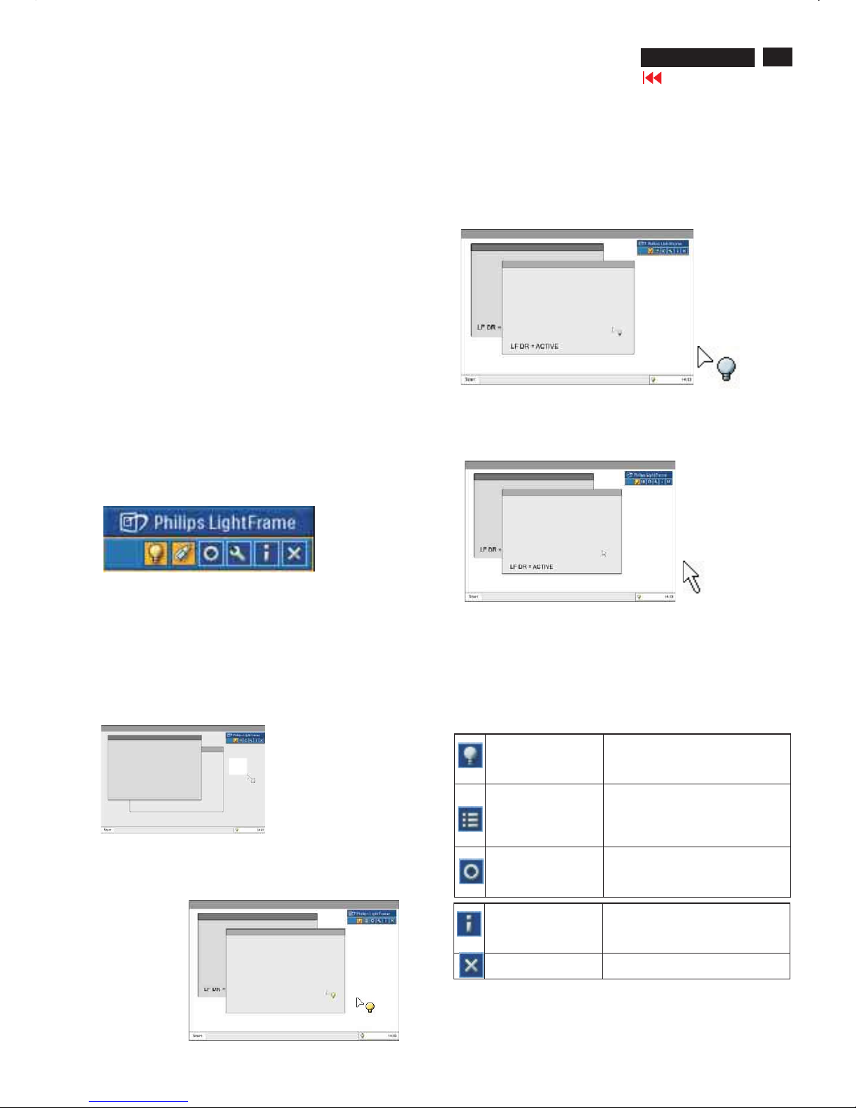
1. Cursor with a yellow light bulb versus a blue light bulb
Yourmouse pointer takes the shape of a light bulb to indicate that
LightFrame
TM
DR is ready to activate or deactivate a target window
that contains photos, videos or other content that canbeenhanced.
Ayellowlight bulb means that you are movingoverawindowwhere
LightFrame
TM
DR canbeactivated. Click on the window to activate
enhancement.Ablue light bulb appearswhen movingoveran
activatedwindow. Click on the window to de-activate LightFrame
TM
DR.
Cursor examples
Here is a listof LightFrame
TM
DR cursors.
This is the defaultcursor displayedwhenyou move over a
non-LightFrame
TM
DR enhancedwindow or area.Clickingand
draggingthis cursor over a window or area activates LightFrame
TM
DR
enhancement.
Yourcursor becomes a yellowlight bulb when it passes over a
non-active window to indicate that LightFrame
TM
DR canbe
activated in the selectedwindow. Click to activate LightFrame
TM
DR
in the selectedwindow. To activate LightFrame
TM
DR simultaneously
in atotal ofuptoeightwindows, click on the selectedwindows
one-by-one whilepressingtheShift key.
Yourcursor becomes a blue light bulb when it passes over an act ive
LightFrame
TM
DR window. C lick to deactivate LightFrameTMDR in the
selectedwindow.
The normal cursor is restored after you click on atargetwithoutpressing
the shift key or after youdrag a rectangle.
2. LightFrame
TM
DR controlbar
The LightFrame
TM
DR controlbar appears at the top ofscreen after any
LightFrame
TM
DR function is activated.
The controlbar is another upgradethathelpsyou run all LightFrame
TM
Digital Reality's neat,newfeatures. The illustrationbelowdescribes the
tasks each button performs.
To drag the controlbar to any preferred area ofyour screen, leftclick the
LightFrame
TM
DR logo.(See examplesbelow) This area isnot a button.
Activate or deactivate
LightFrameTM DR
icon
Turns LightFrameTM DR on and off.
When LightFrameTM DR is active in
a selectedwindow, the icon changes
from bluetoyellow.
Activate or
deactivate the
modemenu icon
The defaultmodemenu icon
appearswhennomodeisselected.
Whenyouselect the photo,Internet
or other mode, the iconfor the
selected mode appears.
Deactivate all
LightFrameTM DR
windows icon
Deactivates all LightFrameTM DR
windows. Thisfunction is only visible
when LightFrameTM DR windows
are active.
InfomodeiconActivates and deactivates the Info
mode,which provides information
abouttoolbar and menu items as
well as access to Help files.
Exit iconClick to exit the LightFrameTM DR
controlbar
24
190P6&170P6 LCD
Go to cover page
LightFrame DR
TM
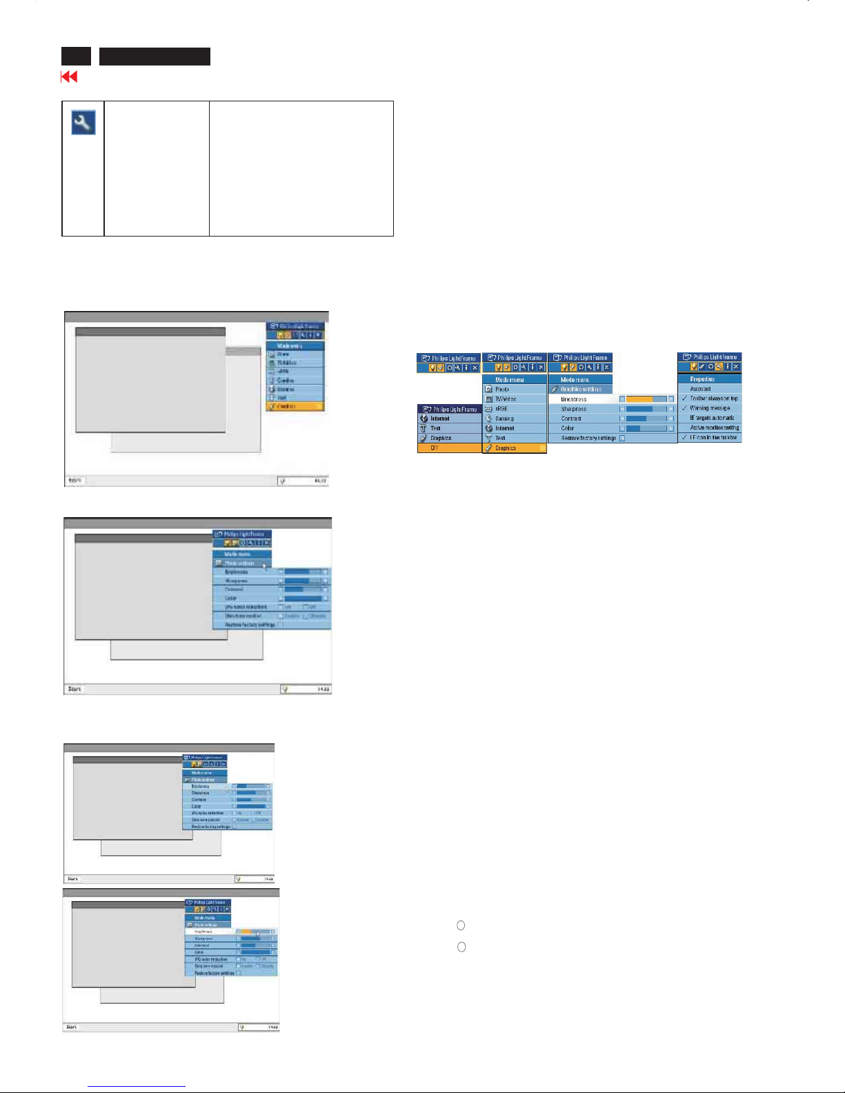
Properties icon Provides access to the Properties
menu, whichincludes these options:
LightFrameTM DRautostart:Yes/no
Position: LightFrameTM DR Always
on top
Warningmessages: On/off
Target selection: Automatic/manual
Monitor selection: Chos
eamongtwo
monitors connected to the same PC
Place LightFrameTM DRicon in the
taskbar:Yes/no
3. Optimizing LightFrameTM DR settings
Here's how tooptimize LightFrameTM DR settings toyour personal
preferences:
1.Select your desired mode fromthemode Menu. Click toopen the mode.
The settings menu
2.
3.Change settingsbypullingthecolor bar or pressi ngtheplus (+) or
minus (-) button to moveincrementally to the desiredlevels.
When you're finished, click on the Modeicon to exit the menu.
4. LightFrameTM Hot Key
The LightFrameTM Hot Key islocated at front of LightFrameTM DR
monitor.
The blue LED isonwhenLightFrameTM is activated and off when
the feature isdeactivated. A touch on the Hot K
eyquickly provides
full screen enhancementinyour choice of the Internet,Photoor
Video-TV mode.
Whenyoutouchthefront button, a small OSD window opens on
your screendirectly abovethebutton location.
Usethisscreen toselectthebe
st full screen mode forthe
application you're working with.Press continuously on the Hot Key
toscroll through the available options.
1) WhenyoutouchtheLightFrameTM Hot Key, anOSDwindow
opens. Touchthebutton continually toscroll amongtheavailable
Internet,Phot
o and Video-TV modes. As amode becomes
available for selection, itscolor changesfrom bluetoyellow.
Once you reachthedesired mode, remove your finger from
the Hot Key. A fter three seconds, the mode you have selec
ted
will be confirmed and the OSD window will automatically close.
2) TouchtheLightFrameTMDR Hot Keyfor three seconds to enter
the LightFrame
TM
demo mode.Toexit the demonstration mode,press
the hot key again.
5. Language
While Englishis the default language of LightFrame
TM
DR,Dutch,
French,German, Italian, Portuguese,Spanish,SimplifiedChinese,
TraditionalChineseand Korean are supported. LightFrame
TM
DR will
detectthelanguage of computer system OS and selectthelanguage
automatically.
Notes
Philips LightFrame
TM
DR only works with monitorsspecially builttouse
thissoftware.IfLightFrame
TM
DR detects that yourmonitorisnot
LightFrame
TM
DR-compatible, amessage appearsonthe monitor screen.
If you see this message,youcan abort or continuetheinstallation;
however, ifyoucontinuetheinstallation, LightFrame
TM
DR will probably
not workonthe monitor.
How touse LightFrame
TM
DR
After installation,LightFrame
TM
DR shortcuticon appearsonyour screen
whenever the computer isstarted.
To learn more about using LightFrame
TM
Digital Reality, pleaserefer to
the help information, whichis availableafter installation.
Com patibility
Thisversion of LightFrame
TM
DRiscompatible with:
Windows XP
Windows 2000 ProfessionalEdition with Service Pack 2
How to downloadyour upgradedLF DR Ins tallation file
Visit http://www.philips.com/support
R
R
25
190P6&170P6 LCD
Go to cover page
All units that are returned for service or repair must pass the
original manufactures safety tests. Safety testing requires both
and testing.Hipot Ground Continuity
HI-POT TEST INSTRUCTION
1.Application requirements
2.
1.1 All mains operated products must pass the Hi-Pot test as
described in this instruction.
1.2 This test must be performed again after the covers have
been refitted following the repair, inspection or modification
of the product.
2.1 Connecting conditions
2.1.1 The test specified must be applied between the parallel-
blade plug of the mainscord and all accessible metal
parts of the product.
2.1.2 Before carrying out the test, reliable conductive
connections must be ensured and thereafter be
maintained throughout the test period.
2.1.3 The mains switch(es) must be in the "ON" position.
2.2 Test Requirements
All products should be HiPot and Ground Continuity tested as
follows:
Test 2820VDC 1700VDC Test current:
voltage (2000VAC) (1200VAC) 25A,AC
Test time:
Test time 3 seconds 1 second 3 seconds(min.)
(min.) Resistance
required:
Trip set at 100 uA 5 mA <=0.09+Rohm,
current for Max. R is the
(Tester) limitation; set resistance of
at 0.1 uA for the mains cord.
Min. Limitation
Ramp set at 2
time seconds
(Tester)
Test method
Condition HiPot Test for HiPot Test for Ground Continuity
products where products where Test requirement
the mains input the mains input is
range is Full 110V AC(USA
range(or 220V type)
AC)
2.2.1 The minimum test duration for Quality Control Inspector
must be 1 minute.
2.2.2 The test voltage must be maintained within the specified
voltage + 5%.
2.2.3 There must be no breakdown during the test.
2.2.4 The grounding blade or pin of mains plug must be
conducted with accessible metal parts.
3. Equipments and Connection
3.1. Equipments
For example :
- ChenHwa 9032 PROGRAMMABLE AUTO SAFETY
TESTER
- ChenHwa 510B Digital Grounding Continuity Tester
- ChenHwa 901 (AC Hi-pot test), 902 (AC, DC Hi-pot test)
Withstanding Tester
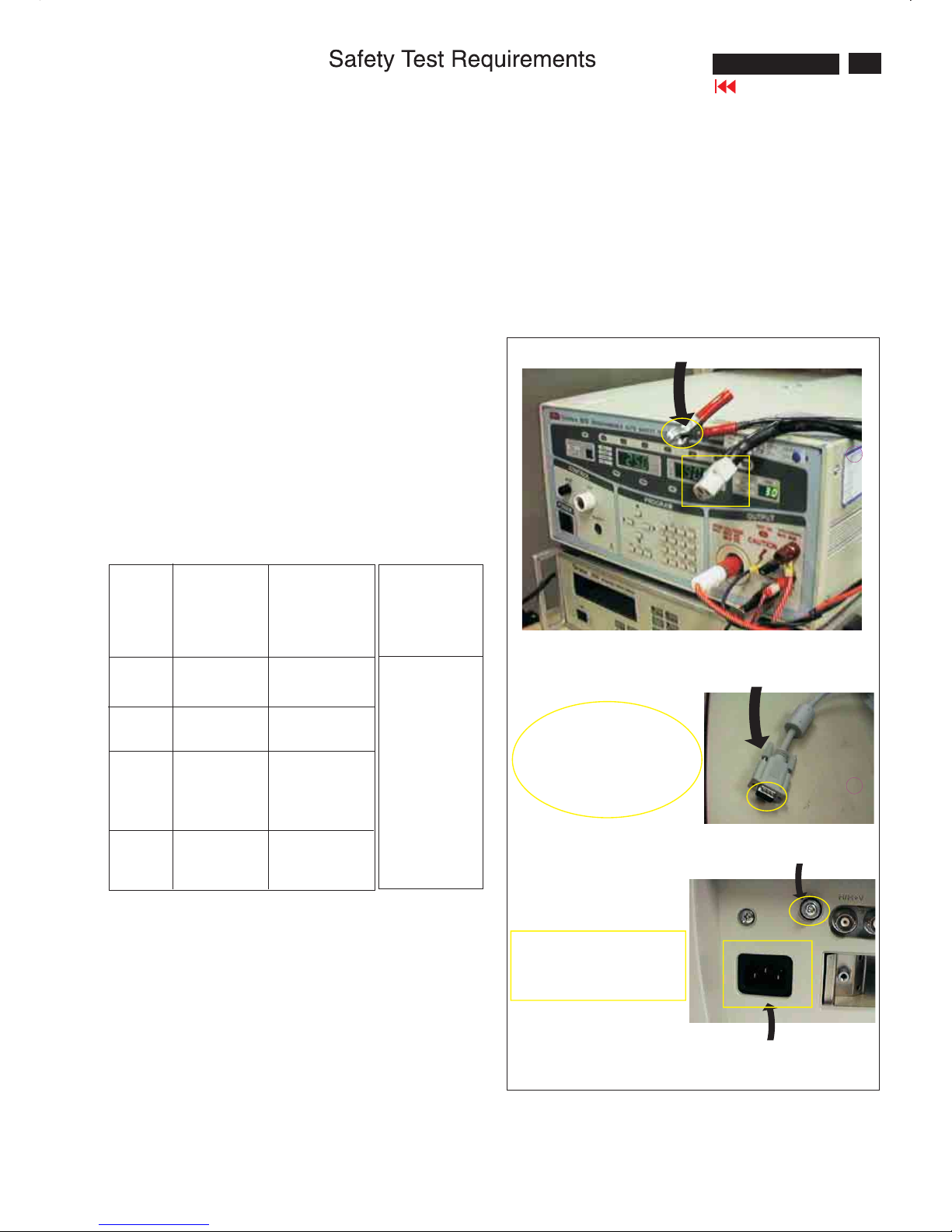
3.2. Connection
4. Recording
Hipot and Ground Continuity testing records have to be kept
for a period of 10 years.
* Turn on the power switch of monitor before Hipot and
Ground Continuity testing.
Connect the "video cable"
or "grounding screw"
to the CLIP on your tester.
Video cable
(Rear view of monitor)
Connect the power cord
to the monitor.
Grounding screw
Power outlet
(ChenHwa 9032 tester)
Clip
Clip
26
190P6&170P6 LCD
DDC Instructions
To Monitor
D-sub/DVI cable
DC 8~12V
To Printer port
Power
indicator
To Monitor
D-sub cable
DC 8~12V
To Printer port
Power
indicator
General
DDC Data Re-programming
Analog DDC IC, & EEPROM
Additional information
In case the DDC data memory IC or main EEPROM which storage all
factory settings were replaced due to a defect, the serial numbers have
to be re-programmed" ".
It is advised to re-soldered DDC IC and main EEPROM from the old
board onto the new board if circuit board have been replaced, in this case
the DDC data does not need to be re-programmed.
Additional information about DDC (Display Data Channel) may be
obtained from Video Electronics Standards Association (VESA).
Extended Display Identification Data(EDID) information may be also
obtained from VESA.
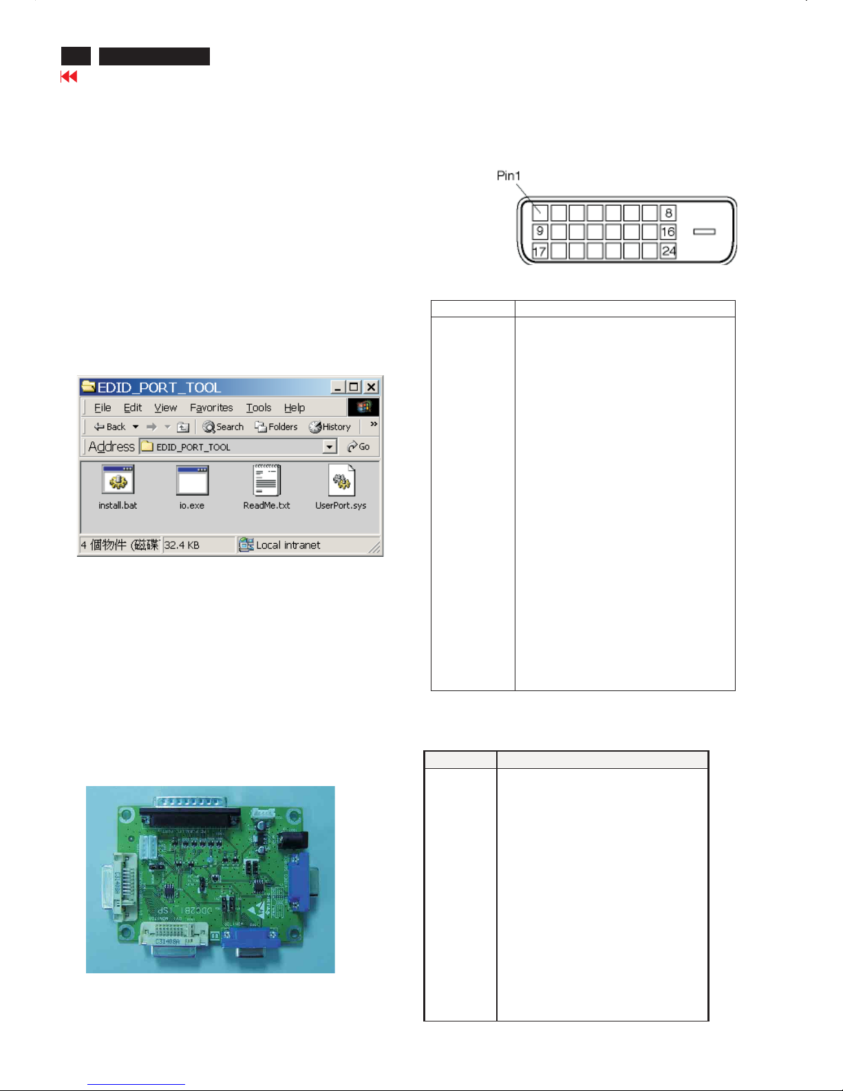
1. An i486 (or above) personal computer or compatible.
2. Microsoft operation system Windows 95/98 .
Y o Install the EDID_PORT_Tool under Win2000/XP . As
Fig. 1 .
A. Cody the "UserPort.sys" to C:\WINNT\system32\drivers(win2000)
C:\WINDOWS\system32\drivers(winXP)
B. Running " io.exe" everytime, Before you start to programming
edid data .
4. DDC 2BI-ISP TOOL:
Inclusion :
A. DDC2BI-ISP TOOL(3138 106 10396) x1 (as Fig. 2)
B. Printer cable x1
c. (D-Sub) to (D-Sub) cable x2
D. D-SUB to DVI cable X1
Note: The EDID46.EXE is a windows-based program, which cannot
beruninMS-DOS.
System and equipment requirements
ou have t
3. EDID46 Release For writing block4.EXE program .
Fig. 2Fig. 2
Fig. 1Fig. 1
Pin Assignment
The digital only connector contains 24 signal contacts organized in
three rows of eight contacts. Signal pin assignments are listed in the
following table:
Fig. 3Fig. 3
Fig. 4Fig. 4
Pin No. Description
1 T.M.D.S. data2-
2 T.M.D.S. data2+
3 T.M.D.S. data2 shield
4 No Connect
5 No Connect
6 DDC clock
7 DDC data
8 No Connect
9 T.M.D.S. data1-
10 T.M.D.S. data1+
11 T.M.D.S. data1 shield
12 No Connect
13 No Connect
14 +5V Power
15 Ground (for +5V) – Cable detect
16 Hot plug detect
17 T.M.D.S. data0-
18 T.M.D.S. data0+
19 T.M.D.S. data0 shield
20 No Connect
21 No Connect
22 T.M.D.S clock shield
23 T.M.D.S. clock+
24 T.M.D.S. clock-
Input analog D-sub connector pin assignment
PIN No. SIGNAL
1 Red video input
2 Green video input / sync on green
3 Blue video input
4 GND
5 GND
6 Red video GND
7Green video GND
8 Blue video GND
9 DDC +3.3V or +5V
10 Logic GND - Cable detect
11 GND
12 Serial data line (SDA)
13 H-sync / H+V
14 V-sync
15 Data clock line (SCL)
Go to cover page
27
190P6&170P6 LCD
DDC Instructions
Step 3: Installation of EDID45.EXE
Method 1: Start on DDC program
Start Microsoft Windows.
1. The Program"EDID45.EXE" in service manual cd-rom be copyed to C:\ .
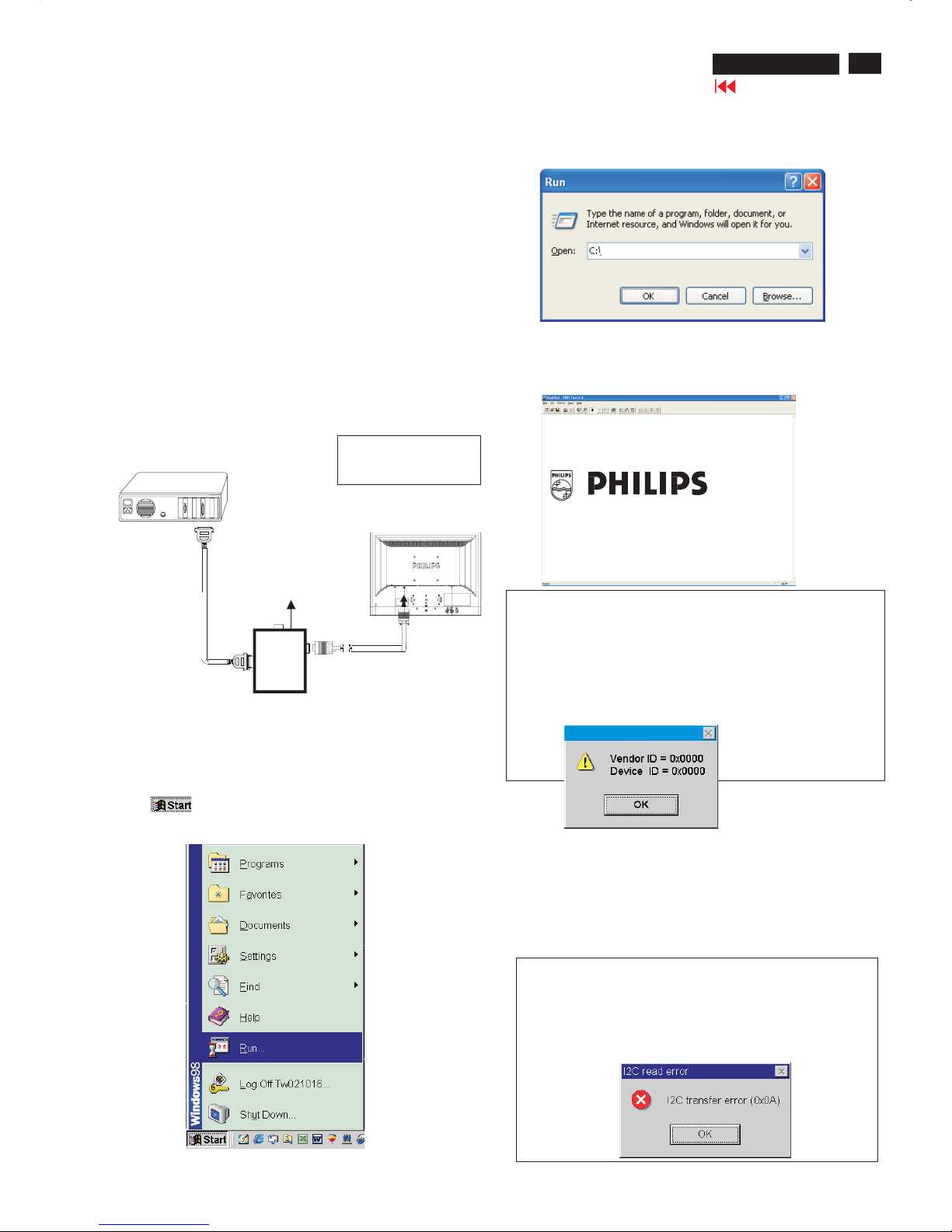
2. Click , choose Run at start menu of Windows as shown
In Fig. 6.
Fig. 6
4. Click button. The main menu appears (as shown in Fig. 8).OK
This is for initialize alignment box.
Fig. 8
Fig. 7
Fig. 9
Note 1: If the connection is improper, you will see the following error
message (as shown in Fig. 9) before entering the main menu.
Meanwhile, the (read EDID) function will be disable. At this time,
please make sure all cables are connected correctly and fixedly,
and the procedure has been performed properly.
3. At the submenu, type the letter of your computer's hard disk drive
followed by :EDID45 (for example, C:\EDID45, as shown in Fig. 7).
Note 2: During the loading, EDID45 will verify the EDID data which just
loaded from monitor before proceed any further function, once the
data structure of EDID can not be recognized, the following error
message will appear on the screen as below. Please
confirm following steps to avoid this message.
1. The data structure of EDID was incorrect.
2. DDC IC that you are trying to load data is empty.
3. Wrong communication channel has set at configuration setup
windows.
1
Configuration and procedure
There are 3 chips contained OSD string, serial number..etc
on the circuit board, main EEPROM which storage all factory settings,OSD
string. DDC IC which storage 128byte EDID data(serial number ..etc.).
Following descirptions are the connection and procedure for Analog
/Digital and main EEPROM can be re-programmed along with
Analog/Digital IC by enable factory memory data write function on the
DDC program (EDID45.EXE).
Initialize alignment box
In order to avoid that monitor entering power saving mode due
to sync will cut off by alignment box, it is necessary to initialize
alignment box before running programming software
(EDID45.EXE). Following steps show you the procedures and
connection.
Step 1: Supply 8-12V DC power source to the Alignment box by
plugging a DC power cord or using batteries.
Step 2: Connecting printer cable and D-Sub cable of monitor as Fig. 5
Fig. 5
PC
1=Power connector
2=D-SUB/DVI connector
To printer port (LTP1)
DC Power
8-12 V
Fig. 10
Printer
Port
To Monitor
To PC
2
----->
1
----->
Edid45.exe
Edid45.1
Go to cover page
28
190P6&170P6 LCD
DDC Instructions
PC
To printer port (
LTP1)
Printer
Port
To Monitor
To PC
To Monitor
D-sub/DVI cable
DC 8~12V
To Printer port
Re-programming Analog DDC IC
Step 1: After initialize alignment box, connecting all cables and
box as shown in Fig. 11
Fig. 12
Step 2: Read DDC data from monitor
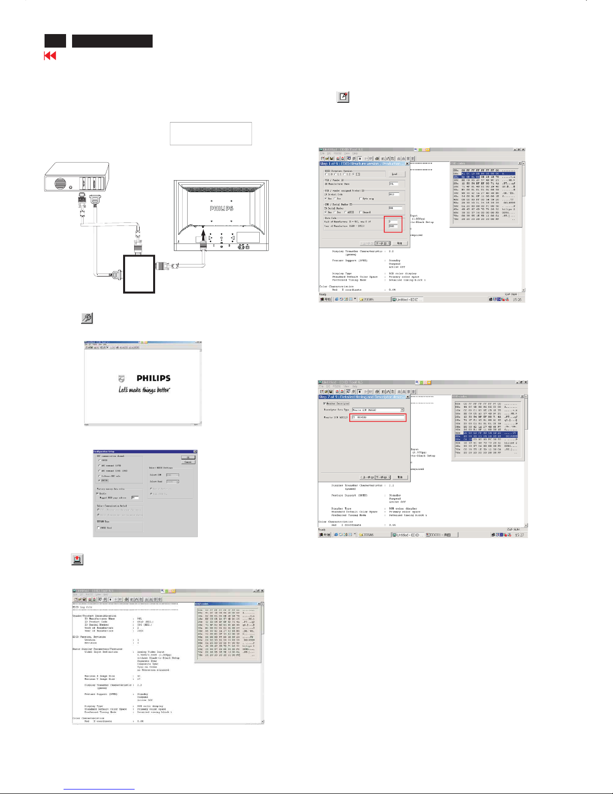
1. Click iconasshowninFig.11 from the tool bar to bring up
the Channels "Configuration Setup" windows as shown in Fig. 12.
Step 3: Modify DDC data (verify EDID version, week, year)
1. Click (new function) icon from the tool bar, bring up
Step 1 of 9 as shown in Fig. 15.
EDID45 DDC application provides the function selection and
text change (select & fill out) from Step 1 to Step 9.
Step 4: Modify DDC data (Monitor Serial No.)
Next
1. Click to step7, bring up Fig. 16.
- Serial number can be filled up or be changed at this moment.
- Click next,Finish to exit the Step window.
3. Click OK button to confirm your selection.
4. Click icon (Read EDID function) to read DDC EDID data from
monitor. The EDID codes will display on screen as shown in Fig. 14.
Fig. 16
2. Select the DDC2Bi as the communication channel.
As shown in Fig. 13.
Fig. 11
1=Power connector
2=D-SUB connector
Fig. 13
Fig. 14
Fig. 15
Don't close this screen. --->
Select and fill out,
If necessary.
Go to cover page
29
190P6&170P6 LCD
DDC Instructions
To Monitor
D-sub/DVI cable
DC 8~12V
To Printer port
Re-programming Digital DDC IC
Step 1: After initialize alignment box, connecting all cables and
box as shown in Fig. 17
Fig. 18
Step 2: Read DDC data from monitor
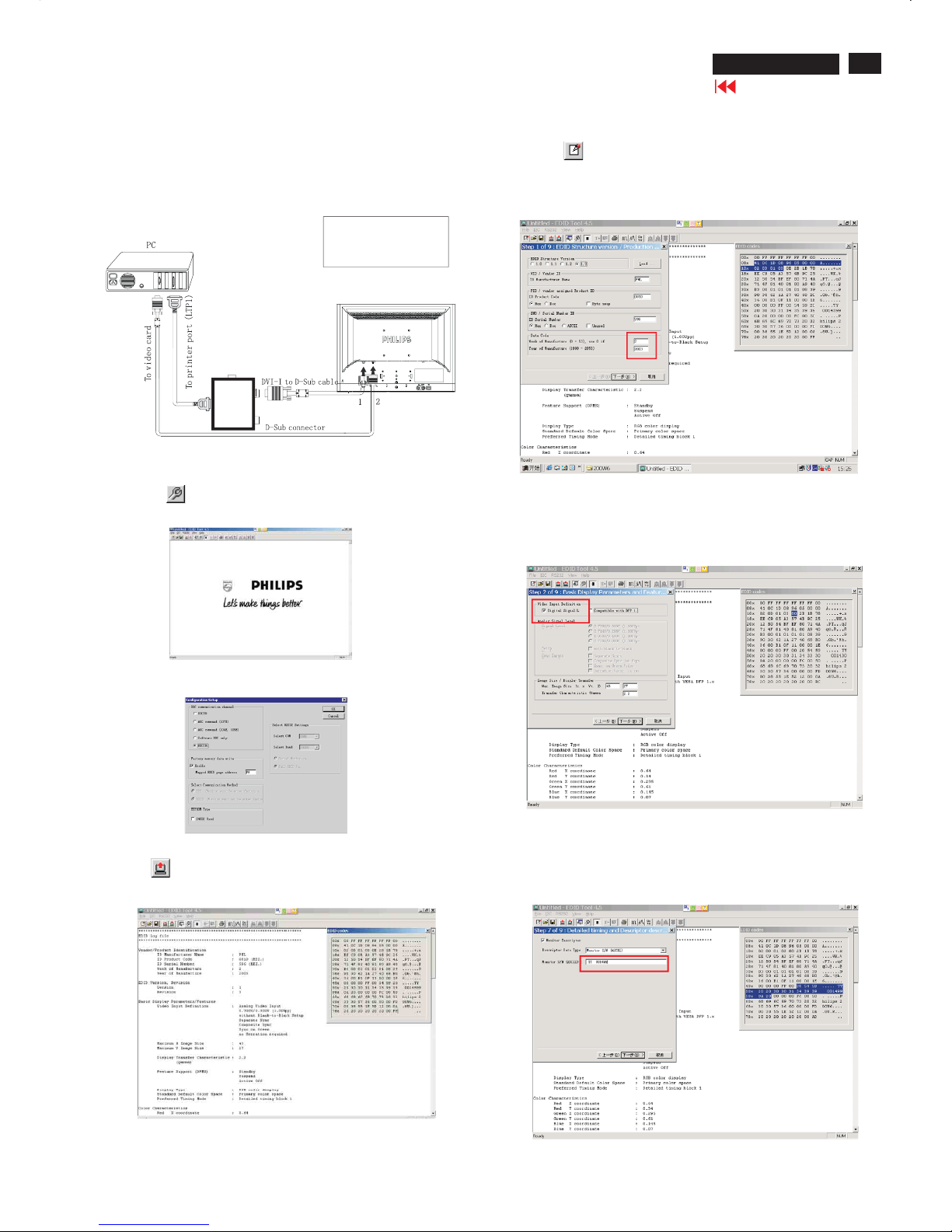
1. Click icon as shown in Fig. 18 from the tool bar to bring up
the Channels "Configuration Setup" windows as shown in Fig. 19.
Step 3: Modify DDC data (verify EDID version, week, year)
1. Click (new function) icon from the tool bar, bring up
Step1of9asshowninFig.21.
EDID45 DDC application provides the function selection and
text change (select & fill out) from Step 1 to Step 9.
Step 4: Modify DDC data (Monitor Serial No.)
Next
1. Click , bring up Fig. 22. Then select Digital Signal as below
3. Click OK button to confirm your selection.
4. Click icon (Read EDID function) to read DDC EDID data from
monitor. The EDID codes will display on screen as shown in Fig. 20.
Fig. 22
Fig. 23
2. Select the DDC2Bi as the communication channel.
As shown in Fig. 19.
Fig. 19
Fig. 20
Fig. 21
Fig.17
Printer
Port
To Monitor
To PC
1=DVI connector
2=D-SUB connector
3=Power Plug
3
Don't close this screen. --->
To Monitor
D-sub/DVI cable
DC 8~12V
Select and fill out,
If necessary.
2. Click to step7, bring up Fig. 23.Next
- Serial number can be filled up or be changed at this moment.
- Click Next, Finish to exit the Step window.
Go to cover page
30
190P6&170P6 LCD
DDC Instructions
Step 6: Save DDC data
Sometimes, you may need to save DDC data as a text file for using
in other IC chip. To save DDC data, follow the steps below:
1. Click (Save) icon (or click "file"-> "save as") from the tool bar
And give a file name as shown in Fig. 25.
The file type is EDID46 file (*.ddc) which can be open in WordPad.
By using WordPad, the texts of DDC data & table (128 bytes, hex
code) can be modified. If DDC TEXTS & HEX Table are completely
correct, it can be saved as .ddc flie to re-load it into DDC IC for DDC
Data application.
2. Click .Save
Step 7: Exit DDC program
Pull down the File menu and select Exit as shown in Fig. 26.
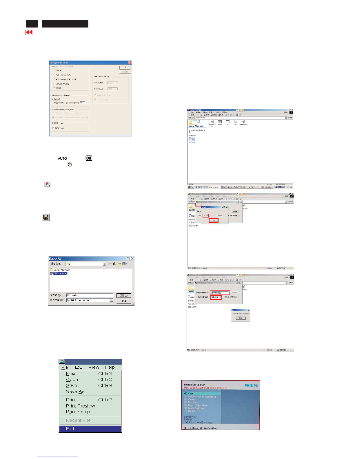
Step 5: Write DDC data
1. Configuration should be as Fig. 24. And press OK.
3. Click (Write EDID) icon from the tool bar to write DDC data.
Fig. 24
Fig. 26
Fig. 25
2. Access Factory Mode
[Push AUTO " " & OK " " buttons at the same time and hold
it]+[Press power " " button untill comes out "Windows screen"]
=> then release all button
- Turn off monitor.
-
Step9:
-1. Disconnect the monitor power cord and connect it again.
-2. Press the OK button to bring up the OSD main manu.
-3. Re-confirm the serial Number is updated as shown in Fig.31.
Step :8 Modify serial number in OSD
-1. Unzip the serial number.zip to your computer, then open the folder
as shown in Fig.28.
-2.IfuseWin98 OS, you can execute SN.exe directly.
If use Win2000 or XP OS, first, you must execute install.bat, then
execute SN.exe
-3. Set I2C bus(press the left-top button of operating window) as shown
in Fig.28, then press " SET" button.
-4. Set Block4 as shown in Fig.30
-5. key in new serial number, then press " Write" button as shown in
Fig.30 , Click " WRITE" button.
-6. It will appear" Serial Number Write OK" , Click" Enter" to finish it.
Fig.28
Fig.29
Fig.30
Edid45.1
Fig.31
190P6
Go to cover page
 Loading...