

Philips 190EW9FB 00, 190EW9FB 93, 190EW9FB 05, 190EW9FB 62 Service Manual
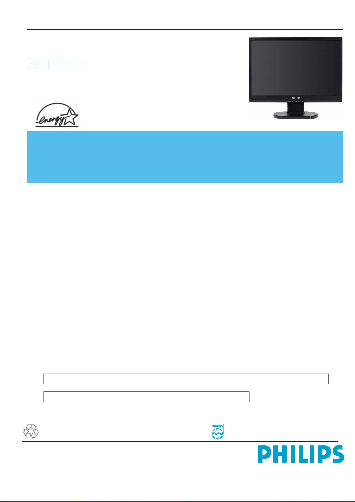
19” TFT LCD COLOR MONITOR
Service
Service
190EW9FB/00
190EW9FB/93
190EW9FB/05
190EW9FB/62
190EW9 LCD 1
Service
Manual
TABLE OF CONTENTS
Description
Important Safety Notice ............................................. 2
Technical Data & Power Management ....................... 3 ~ 4
Connection to PC ....................................................... 5
OSD Menu Control Level Structure ........................... 6
Advanced OSD Adjustment ....................................... 7
OSD Attention Signal ................................................. 8
Safety and troubleshooting information .................... 9
Definition of Pixel Defects .......................................... 10 ~ 11
Wiring Diagram .......................................................... 12
Mechanical Instructions ............................................. 13 ~ 14
F/W Upload Instructions ............................................ 15 ~ 15
DDC Instructions ........................................................ 16 ~ 17
DDC DATA ................................................................. 18 ~ 18
Safety Instructions, Warnings and Notes ................... 19
Block Diagram ........................................................... 20
Copyright 2008 Philips Consumer Lifestyle. All rights reserved. No part of this publication
may be reproduced, stored in a retrieval system or transmitted, in any form or by means,
electronic ,mechanical, photocopying, or otherwise without the prior permission of Philips.
Safety regulations require that the set is restored to its original condition and that parts
which are identical with those specified are used.
SAFETY NOTICE
ANY PERSON ATTEMPTING TO SERVICE THIS CHASSIS MUST FAMILIARIZE HIMSELF WITH THE CHASSIS
AND BE AWARE OF THE NECESSARY SAFETY PRECAUTIONS TO BE USED WHEN SERVICING ELECTRONIC
EQUIPMENT CONTAINING HIGH VOLTAGES.
CAUTION: USE A SEPARATE ISOLATION TRANSFORMER FOR THIS UNIT WHEN SERVICING.
REFER TO BACK COVER FOR IMPORTANT SAFETY GUIDELINE.
http://www.wjel.net
Page
Description
Scaler Board Schematic Diagram ..............................21 ~ 23
Power Board Schematic Diagram ..............................24 ~ 25
Button Board Schematic Diagram ............................. 26
Scaler Board Layout Side View ................................. 27
Power Board Layout Side View ................................. 28
Exploded View ...........................................................29
Recommended Parts List .......................................... 30~33
Different Parts List .................................................... 34
General Trouble Shooting Guide ............................... 34~48
General Product Specification ................................... 49 ~ 61
Safety Check Process ...............................................
Subject to modification
EN:
Page
62
Jul.
17th. 2008
312278517990
190EW9 LCD 2
Important Safety Notice
Proper service and repair is important to the safe, reliable
operation
Equipment.
and
performing
operations
purpose.
recommended.
of
all Philips Consumer Electronics Company**
The service procedures recommended by Philips
described in this service manual are effective methods of
service operations. Some of these service
require the use of tools specially designed for the
The special tools should be used when and as
It is important to note that this manual contains various
CAUTIONS
order
personnel.
methods
understand
EXHAUSTIVE.
advise
service
consequences
undertaken
servicer
recommended
that
will
be
and NOTICES which should be carefully read in
to
minimize the risk of personal injury to service
The possibility exists that improper service
may damage the equipment. It is also important to
that these CAUTIONS and NOTICES ARE NOT
the service trade of all conceivable ways in which
might be done or of the possible hazardous
neither his safety nor the safe operation of the equipment
jeopardized by the service method selected.
Philips could not possibly know, evaluate and
of
each way. Consequently, Philips has not
any such broad evaluation. Accordingly , a
who uses a service procedure or tool which is not
by
Philips must first satisfy himself thoroughly
* * Hereafter throughout this manual, Philips Consumer
Electronics Company will be referred to as Philips.
WARNING
Critical components having special safety characteristics are
identified
enclosed
(where several critical components are grouped in one
area)
or exploded views.
Use of substitute replacement parts which do not have the
same
or
Under no circumstances should the original design be
modified
Philips
any
Servicer assumes all liability .
* Broken Line
with a
by
within a broken line*
along with the safety symbol
specified safety characteristics may create shock, fire,
other hazards.
or
altered without written permission from Philips.
assumes no liability , express or implied, arising out of
unauthorized modification of design.
the Ref. No.in the parts list and
on
http://www.wjel.net
the schematics
FOR PRODUCTS CONTAINING LASER :
DANGER -
In
AVOID
visible laser radiation when open.
DIRECT EXPOSURE TO BEAM.
CAUTION -
Use of controls or adjustments or
performance
those
hazardous
of
procedures other than
specified herein may result in
radiation exposure.
CAUTION -
The use of optical instruments with this
Product will increase eye hazard.
TO ENSURE THE CONTINUED RELIABILITY OF THIS
PRODUCT,
REPLACEMENT
THEIR
THIS SERVICE MANUAL.
OF
Take care during handling the LCD module with backlight
unit
- Must mount the module using mounting holes arranged in
four corners.
- Do not press on the panel, edge of the frame strongly or
electric shock as this will result in damage to the screen.
- Do not scratch or press on the panel with any sharp objects,
such as pencil or pen as this may result in damage to the
panel.
- Protect the module from the ESD as it may damage the
electronic circuit (C-MOS).
- Make certain that treatment persons body are grounded
through wrist band.
- Do not leave the module in high temperature and in areas
of high humidity for a long time.
- Avoid contact with water as it may a short circuit within
the module.
- If the surface of panel become dirty, please wipe it off with
a soft material.( Cleaning with a dirty or rough cloth may
damage the panel.)
USE ONLY ORIGINAL MANUFACTURER'S
PART S, WHICH ARE LISTED WITH
PART NUMBERS IN THE PART S LIST SECTION

Technical Data
1. General Specification
1.1 Panel characteristic
Panel source
Screen type Screen
dimensions
BOE HT190WG1-60 0
Resolution
Outside dimensions
Pixel pitch (mm)
Color pixel arrangement
Display surface
Color depth
Backlight
Active area (mm) View
angle (CR>10) Contrast
ratio
White luminance
Color gamut
Response time
1.2 Scanning frequencies
Horizontal scan range
Vertical scan range
1.3 Video
Video dot rate
Input impedance
(Analog signal input)
- video
- Sync
: BOE HT190WG1-60 0
: TN+film
: 19 inches (diagonal) 16:10
: 1440 X 900 (WXGA+)
: 428.0 (H) X 278.0 (V) X 18.5 (D)
: 0.2835 x 0.2835
: R. G. B. Vertical Stripe
: Hard-coating (3H), Non-glare type
: 16.7M colors
: 4 lamps
: 408.24 (H) x 255.15(V)
: 170 (H)/160(V) (typical)
: 1000 : 1 (typical)
: 300 nits (7.0mA) (typical)
: 72% (typical)
: 5 ms
: 30 - 83 K Hz (automatic)
: 56 - 76 Hz (automatic)
: < 156 MHz
http://www.wjel.net
: 75 ohm
: 2.2K ohm
Input signal levels
Sync. input signals
Input impedance (Digital)
Video interface
1.5 Physical characteristics
Unit dimensions
- Width
- Height
- Depth
Packed unit dimensions
- Width
- Height
- Depth
Packed unit dimensions
(China only)
- Width
- Height
- Depth
Weight (monitor only)
Title angel
Swivel angel
Height adjustment
Portrait display
AC input: - voltage
- frequency
Power consumption
Ambient temperature
Operating
- Temperature
- Humidity
- Altitude
Storage
- Temperature
- Humidity
- Altitude
System MTBF
190EW9 LCD 3
: 700 mVpp
: Analog R/G/B separate inputs
Separate horizontal and vertical /
Composite (H+V) TTL level,
Sync On Green (SOG) sync
0.3Vp-p Negative
: NA
: Analog only
: 437.4 mm
: 374.8mm
: 189.1 mm
: 490.0mm
: 138.0 mm
: 375.0 mm
: 490.0 mm
: 138.0 mm
: 375.0 mm
: 4.0±0.2kg (Including I/F cable
240 g)
: -5 +/∘ -2 ( forward ),
+14 +/∘ -3 ( backward )
: nil
: nil
: nil
: AC 90 - 264 V,
: 50 / 60 + 2 Hz
: 42W maximum
: 0 to 40 degree C
: 0 to 40 degree C
: 90% (max.)
: 0 - 3048 m
: -20 to 60 degree C
: 90% max
:
0 to 9144m
: 50,000 Hrs
190EW9 LCD 4
Technical Data
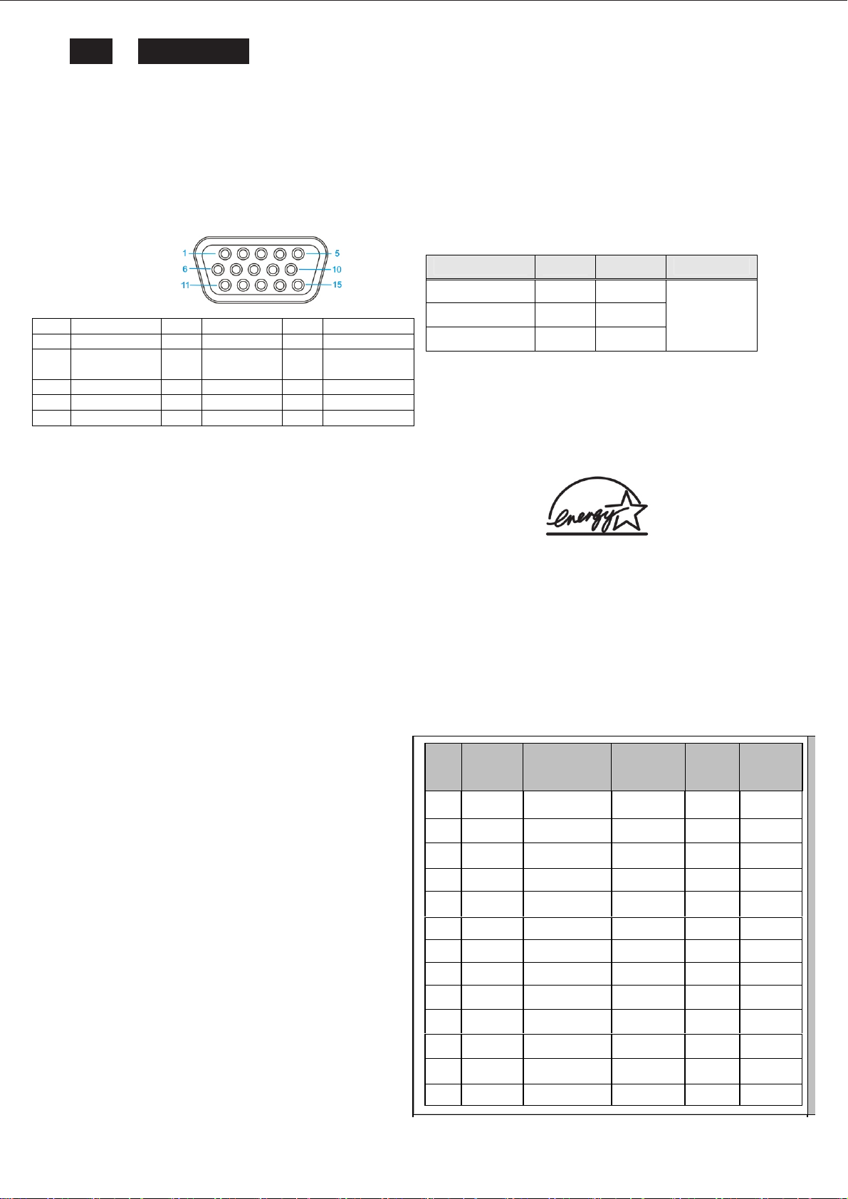
2. Pin Assignment
2.1 PC analog video input with D - sub connector.
Connector type of analog signal cable :
D - Sub male with DDC2B pin assignment.
Blue connector with thumb-operated jackscrews.
Pin assignment :
Pin Symbol Pin Symbol Pin Symbol
1 Red 6 Red GND 11 GND
2 Green/SOG 7
3 Blue 8 Blue GND 13 H sync
4 GND 9 +5V 14 V sync
5 CableDetect 10 Open 15 Data clock
Green
GND
12
Bi-directional
data
Automatic Power Saving
If you have VESA / DPMS compliance display card or
software installed in your PC, the monitor can automatically
reduce power consumption when power saving function
active. And if an input from keyboard, mouse or other
devices is detected, the monitor will automatically wake up.
The following table shows the power consumption and
signaling of this automatic power saving feature:
Status Power
Power On ≤ 42W
Power Saving ≤ 2W
Power Off ≤ 1W
This monitor must comply with the Microsoft On Now
specification,
defined by the VESA DPMS document. And must
appropriately display
DPMS states. Also comply with Environmental Protection
the
Agency
standard strictly.
with two power management states, as
(EPA) Energy Star and TCO03 power management
LED
Green
Amber
Off
Remark
W/O
Speaker
ENERGY
STAR
PRODUCT
ENERGY
Data Storage
http://www.wjel.net
STAR is a U.S. Registered mark. AS AN ENERGY
PART NER, PHILIPS HAS DETERMINED THAT THIS
MEETS THE ENERGY STAR GUIDELINES OF
EFFICIENCY.
Factory preset mode:
following table:
Item H.Freq.
1 31.469 IBM VGA 3H 720x400 70.087 28.3
2 31.469 IBM VGA 12H 640x480 59.94 25.18
3 35 MACINTOSH 640x480 67 30.24
4 37.5 VESA 640x480 75 31.5
5 35.156 VESA 800x600 56.25 36
6 37.879 VESA 800x600 60.317 40
7 46.875 VESA 800x600 75 49.5
8 48.363 VESA 1024x768 60.004 65
9 60.023 VESA 1024x768 75.029 78.75
10 63.981 VESA 1280x1024 60.02 108
11 79.976 VESA 1280x1024 75.025 135
12 55.935 VESA 1440x900 59.887 106.5
13 70.635 VESA 1440x900 74.984 136.8
This monitor has 13 factory-preset modes as indicated in the
(KHz)
Mode Resolution V.Freq.
(Hz)
BW(MHz)
Q
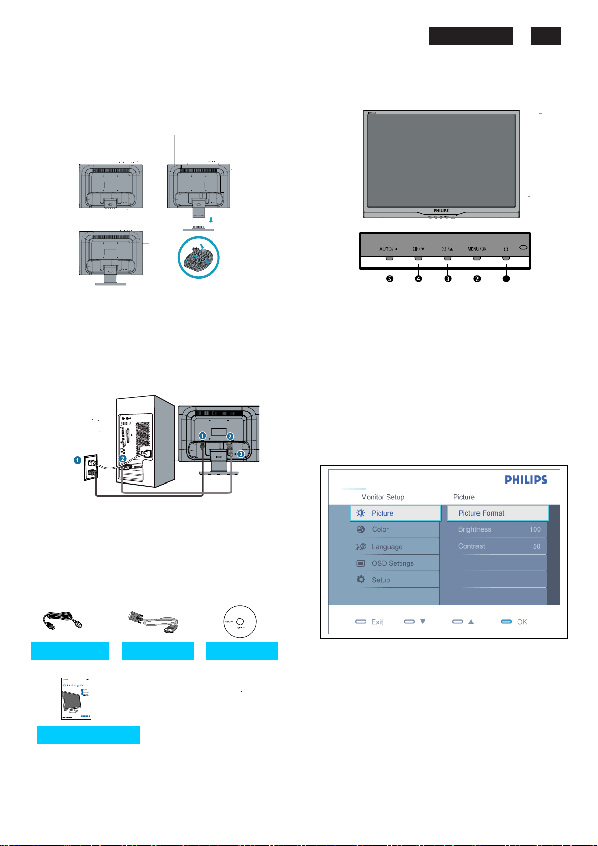
Connection to PC
1. Connection to PC
Please follow the steps to connect your LCD Monitor to PC.
a. Assembly LCD Monitor with base
b. Connect to PC
(1) Turn off your computer and unplug its power cable.
(2) Plug the power cord of your computer and your monitor
Into a nearby outlet.
(3) Turn on your computer and monitor. If the monitor
Displays an image, installation is complete.
Port definition:
(1) AC power input
(2) VGA input
(3) Kensington anti-thief lock
For best performance, use your Analog input
and ensure that your disolay settings are set at
1440*900@60Hz.
c. Accessory Pack
uick start Quide
7
5
6
1
8
6 7
http://www.wjel.net
190EW9 LCD 5
2. Function key definition
(1) To switch monitor’s power on and off.
(2) To access OSD menu,
setting.
(3) To adjust brightness of the display,
(4)To adjust contrast of the display,
(5) Automatically adjust the horizontal position, vertical position,
phase and clock Settings/Return to previous OSD level.
3. Description of the On Screen Display
On-Screen Display(OSD) is a feature in all Philips LCD
monitors. It allows and end user to adjust screen performance
or select functions of the monitors directly through an on-screen
instruction window. A user friendly on screen display interface is
shown as below:
Basic and simple instruction on the control keys.
According to the above OSD structure, users can :
Press ▲ or ▼ button to move the cursor,
Press Menu button confirm the choice or change.
Press ▲ or ▼ button to adjust the value.
Press Menu button to save the changes.
Press AUTO button to automatically adjust the horizontal
position, vertical position, phase and clock setting.
enter the sub-menu, confirm the
go up in the Menu
go down in the Menu

190EW9 LCD 6
OSD Menu Control Structure
4.The OSD tree.
Below is an overall view of the structure of the On-Screen
Display. You can use this as a reference when you want to
work your way around the different adjustments later on.
4.1 Available for EU/AP Mode
4.2 Available for China Model
Note:
sRGB is a standard for ensuring correct exchange of colors
between different devices(e. g. Digital cameras, monitor,
http://www.wjel.net
printers, scanners, etc.)
Using a standard unified color space, sRGB will help
represent pictures taken by an sRGB compatible device
correctly on your sRGB enabled Philips monitor. In that way,
the colors are calibrated and you can rely on the correctness
of the colors shown on your screen.
Important with the use of sRGB is that the brightness and
contrast of your monitor is fixed to a predefined setting as
well as the color gamut. Therefore it is important to select the
sRGB setting in the monitor’s OSD.
To do so, open the OSD by pressing the OK button on the side
of your monitor. More the down button to go to color and
press OK again. Use the right button to go to sRGB. Then
move the down button and press OK again to exit the OSD.
After this, please do not change the brightness or contrast
setting of your monitor. If you change either of these, the
monitor will exit the sRGB mode and go to a color
temperature setting of 6500K.
190EW9 LCD 7
Advanced OSD Adjustment
Advanced OSD Adjustment
1. Front control panel
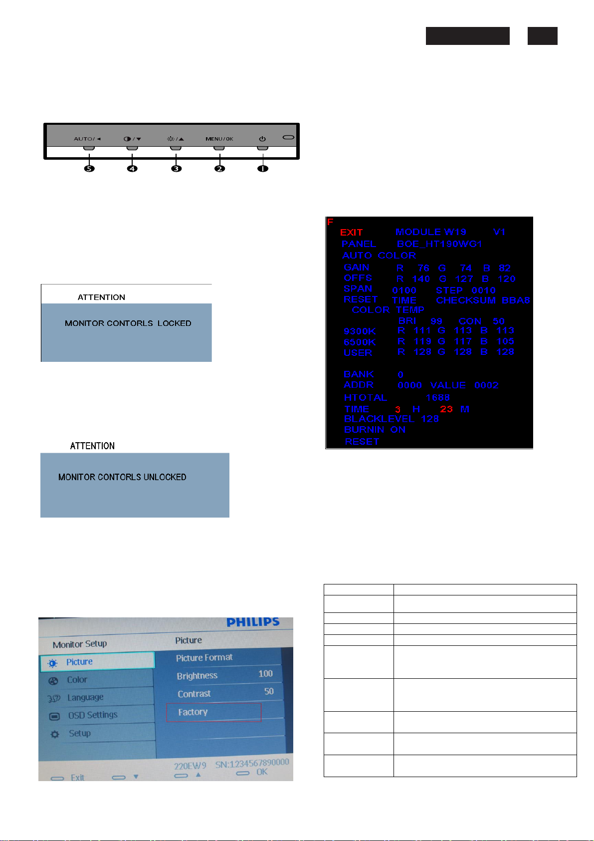
2. To Lock/Unlock OSD function
The OSD function can be locked by pressing MENU button
for more than 6 seconds, the screen shows following windows
for 5 seconds.
Every time when you press any button, this message
appears on the screen automatically.
If this message appeared, means monitor already entered
the factory mode.
4. Entering Burn-in mode and others
If you access into factory mode, pressMENU-PICTURE-
FACTORY, then press MENU to confirm, OSD menu will
convert into another format as below:
Locked OSD function can be released by pressing MENU
button for more than 6 seconds. While press MENU button
for OSD unlocked purpose, the screen will keep showing OSD
MAIN MENU LOCKED until OSD function unlocked and
screen automatically shows following window for 5 seconds.
3. Access Factory Mode
Press POWER button to Power off, then Press AUTO +
MENU at the same time, and then press [POWER] for DC
power on. OSD menu will be shown with “Factory” on the
sub –menu of picture. Select “Factory” for entering factory
mode.
http://www.wjel.net
Move the cursor by MENU button, and press the UP or
DOWN button to change the burn-in mode from On to
Off.
Leave factory mode by simply power off(DC off) the monitor.
Warming:
* If you only want to enter burn in mode, please don’t change
any other setting items as above listed.
Appendix:
Explanation of above listed selections.
Selection Description
Burn in On/Off Enter Aging Mode
Auto Color Auto Color Adjustment
Con Contrast Adjustment
Bri Brightness Adjustment
Gain ADC Gain Value Adjustment
Offset ADC Offset Value Adjustment
9300K 9300K Color Temperature Gain Value
6500K 6500K Color Temperature Gain Value
Reset Memory Racall To Factory Default Settings
(Auto adjustment by H/W when implement
Auto Color function)
(Auto adjustment by H/W when implement
Auto Color function)
Adjustment
Adjustment
190EW9 LCD 8
OSD Attention Signals
Clock & Phase Adjustment
Due to the different quality of video signal generated from
graphics cards. It is necessary to adjust CLOCK and PHASE
functions for the optimal video display of LCD monitor. So
maybe some flicker appeared as Fig.1 & 2.
Fig.1 Fig.2
Following steps will guide you to make correct adjustment of
CLOCK and PHASE:
a. Restart your computer.
b. Press MENU to bring up OSD menu after the OS
(Operation System) boot up.
c. Press
and then press MENU to bring up its submenu as shown in
Fig.3.
d. Select the Clock or Phase adjustment items in submenu
and press
(If the phenomenon as Fig.1, you should adjust “Phase”)
(If the phenomenon as Fig.2, you should adjust “Clock”)
e. Quit OSD by press MENU button to save the settings.
UP or DOWN to select the option of setup
UP or DOWN to adjust.
2. AUTO ADJUSTMENT
This screen appears when you touch the AUTO button. It will
disappear when the monitor is properly adjusted.
3. USE 1440X900@60HZ FOR BEST RESULT
This message appears when the video mode input is not the
recommended 1440*900. Other modes may result in some
picture distortion. Please adjust the video mode to 1440*900 at
60Hz for best display quality.
4. 85HZ OVERDRIVE MESSAGE
This message appears when the video mode input is more
than 85 HZ. The message “THIS IS 85HZ OVERDRIVE,
CHANGE COMPUTER DISPLAY INPUT TO 1440X900@60HZ”
is warmed, around 5 seconds in each minutes,
after 10 minutes will go into power saving mode.
However, CLOCK and PHASE functions are only available while
analog video signal is supplied. Operating unit under digital
signal state, the video clock information can be obtained from
graphics cards directly. So, it is unnecessary to adjust these
functions.
OSD Attention signal
The monitor will detect various display situation automatically.
When the monitor detects the problems, the screen will show
the different warning signals to remind you what is happen to
your monitor.
1. CHECK CABLE CONNECTION
This screen appears if there is no video signal input. Please
check that the signal cable is properly connected to the video
card of PC and make sure PC is on.
Fig.3
http://www.wjel.net
5. NO VIDEO
INPUTÆ
If input VGA you are selecting is not signal input, following
message will appear on the screen.
ENTERING SLEEP MODE
After 5 s, the monitor will go into power saving mode, following
message will appear on the screen.
Please check that the signal available is properly connected to
the video card of PC and make sure PC is on.
Safety and Troubleshooting Information
190EW9 LCD 9
Safety precautions and maintenance
WARNING: Use of controls, adjustments or
procedures
documentation
electrical
other than those specified in this
may result in exposure to shock,
hazards and/or mechanical hazards.
Read and follow these instructions when connecting and using
computer monitor:
your
a. To protect your display from possible damage, do not put
excessive
monitor,
placing
b. Unplug the monitor if you are not going to use it for
an extensive period of time.
c. Unplug the monitor if you need to clean it with a slightly
damp
the
ammonia-based
d. Consult a service technician if the monitor does not operate
normally
manual.
e. The casing cover should be opened only by qualified service
personnel.
f.
Keep the monitor out of direct sunlight and away from
stoves or any other heat source.
g. Remove any object that could fall into the vents or prevent
proper
h. Do not block the ventilation holes on the cabinet.
i.
Keep the monitor dry. To avoid electric shock, do not
expose it to rain or excessive moisture.
j.
When positioning the monitor, make sure the power plug
and outlet are easily accessible.
k. If turning off the monitor by detaching the power cable or DC
power
cable
l.
To
do
m. IMPORTANT: Always activate a screen saver program during
your
the
'after-image' or 'ghost image' on front of the screen. This is a
well-known phenomenon that is caused by the shortcomings
inherent
disappear gradually over a period of time after the power has
been switched off. Be aware, that the afterimage symptom
cannot be repaired and is not covered under warranty.
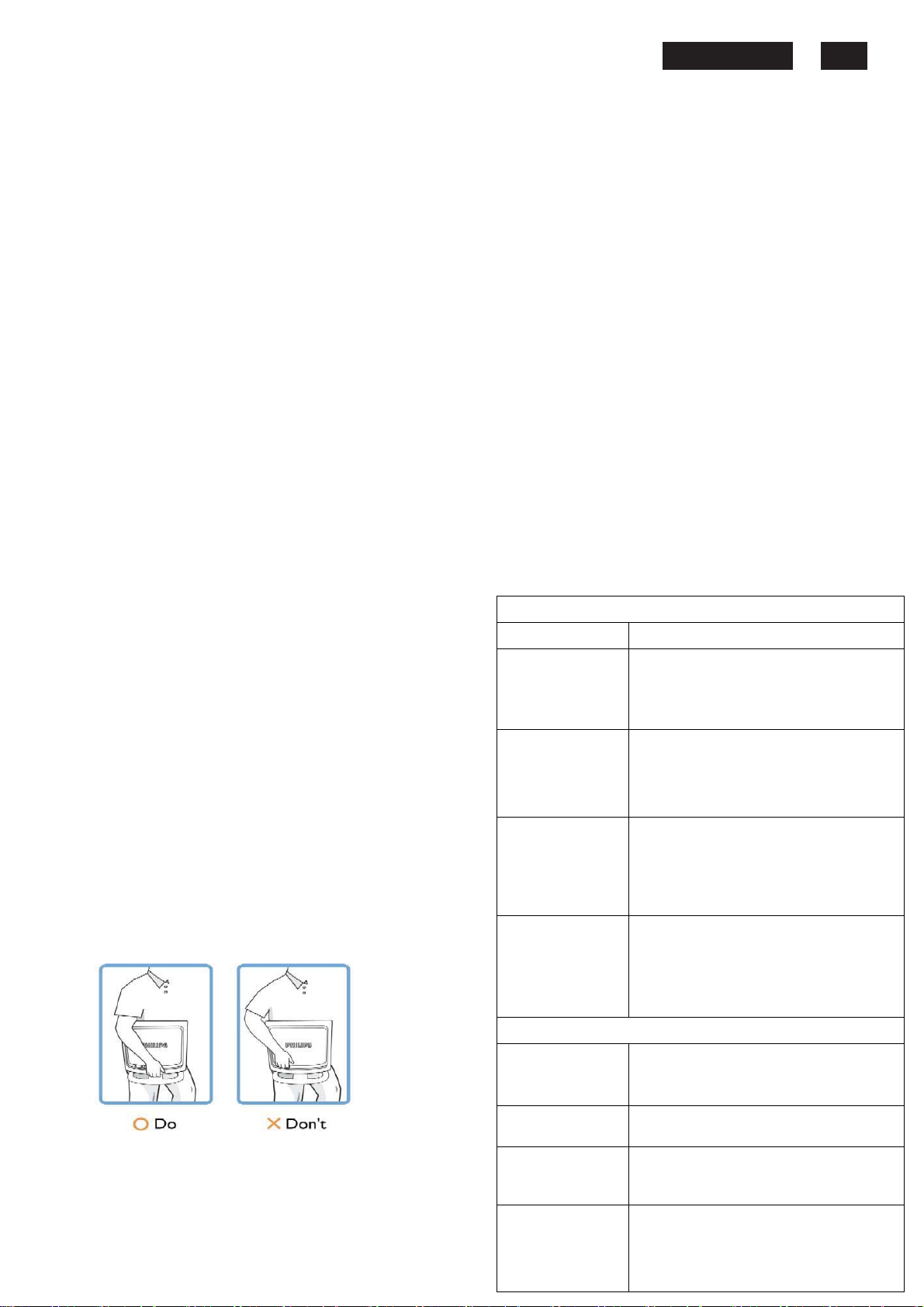
o. Warning for lifting monitor - Do not use the area underneath
the
the logo cover can cause it to break away from the body and
cause
hand
*Consult a service technician if the monitor does not operate
normally
been followed.
have
pressure on the LCD panel. When moving your
grasp the frame to lift; do not lift the monitor by
your hand or fingers on the LCD panel.
cloth. The screen may be wiped with a dry cloth when
power is off. However, never use alcohol, solvents or
cooling of the monitor’s electronics.
cord, wait for 6 seconds before attaching the power
or DC
avoid the risk of shock or permanent damage to the set,
not expose the monitor to rain or excessive moisture.
application. If a still image in high contrast remains on
screen for an extended period of time, it may leave an
in
logo cover to grip or lift the monitor. Placing weight on
the monitor to fall. When lifting the monitor, place one
under the monitor's frame.
when the operating instructions given in this manual
liquids.
when you have followed the instructions in this
power cord for normal operation.
LCD technology. In most cases, the afterimage will
http://www.wjel.net
Installation Locations
Avoid exposure to heat and extreme cold.
Do not store or use the LCD monitor in locations exposed to
heat,
direct sunlight or extreme cold.
Avoid moving the LCD monitor between locations with large
temperature
following
Temperature: 0-35°C 32-95°F
Humidity:
differences. Choose a site that falls within the
temperature and humidity ranges.
20-80% RH
Do not subject the LCD monitor to severe vibration or high
impact
conditions. Do not place the LCD monitor in the trunk of
car.
a
Ta k e care not to mishandle this product by either knocking or
dropping
it
during operation or transportation.
Do not store or use the LCD monitor in locations where there is
a
high level of humidity or in dusty environments. Do not allow
water
or
other liquids to spill on or into the LCD monitor.
Trouble Shooting
This page deals with problems that can be corrected by the
user.
If
the problem still persists after you have tried these
contact your nearest Philips dealer.
solutions,
Common Problems
Having this problem
No Picture
(Power LED not lit)
No Picture
(Power LED is amber
or yellow)
Screen says
AUTO button not
working properly
Imaging Problems
Display position is
incorrect
Image vibrates on the
screen
Vertical flicker appears
Horizontal flicker
appears
Check these items
a. Make sure the power cord is plugged into the
power outlet and into the back of the monitor.
b. First, ensure that the power button on the front
of the monitor is in the OFF position, then
press it to the ON position.
a. Make sure the computer is turned on.
b. Make sure the signal cable is properly
b. connected to your computer.
c. Check to see if the monitor cable has
bent pins. d. The Energy Saving feature
may be activated.
a. Make sure the monitor cable is properly
connected to your computer.(Also refer to the
Quick Set-Up Guide).
b. Check to see if the monitor cable has bent
pins.
c. Make sure the computer is turned on.
a. The Auto Function is designed for use on
standard Macintosh or IBM-compatible PCs
running Microsoft Windows.
b. It may not work properly if using nonstandard
PC or video card.
c. Make sure the computer is turned on.
a. Press the Auto button.
b. Adjust the image position using the
Phase/Clock of More Settings in OSD Main
Controls.
a. Check that the signal cable is properly
connected to the graphics board or PC.
a. Press the Auto button.
b. Eliminate the vertical bars using the
Phase/Clock of More Settings in OSD Main
Controls.
a. Press the Auto button.
b.Eliminate the vertical bars using the
b. Phase/Clock of More Settings in OSD Main
Controls.
190EW9 LCD 10
Definition of Pixel Defects
The screen is too
bright or too dark
An after-image
appears
An after-image
remains after the
power has been
turned off
Green, red, blue,
dark, and white dots
remains
For further assistance, refer to the Consumer Information
Centers list and contact your local Philips distributor.
Adjust the contrast and brightness on On-Screen
Display.(The backlight of the LCD monitor has a
fixed life span. When the screen becomes dark or
begins to flicked, please contact your sales
representative).
If an image remains on the screen for an
extended period of time, it may be imprinted
in the screen and leave an after-image. This
usually disappears after a few hours.
This is characteristic of liquid crystal and is
not caused by a malfunction or deterioration
of the liquid crystal. The after-image will
disappear after a peroid of time.
The remaining dots are normal
characteristic of the liquid crystal used in
today’s technology.
Definition of Pixel Defects
This section explains the different types of pixel defects and
defines acceptable defect levels of each type. In order to
quality for repair or replacement under warranty, the number
of pixel defects on a TFT LCD panel must exceed these
acceptable levels.
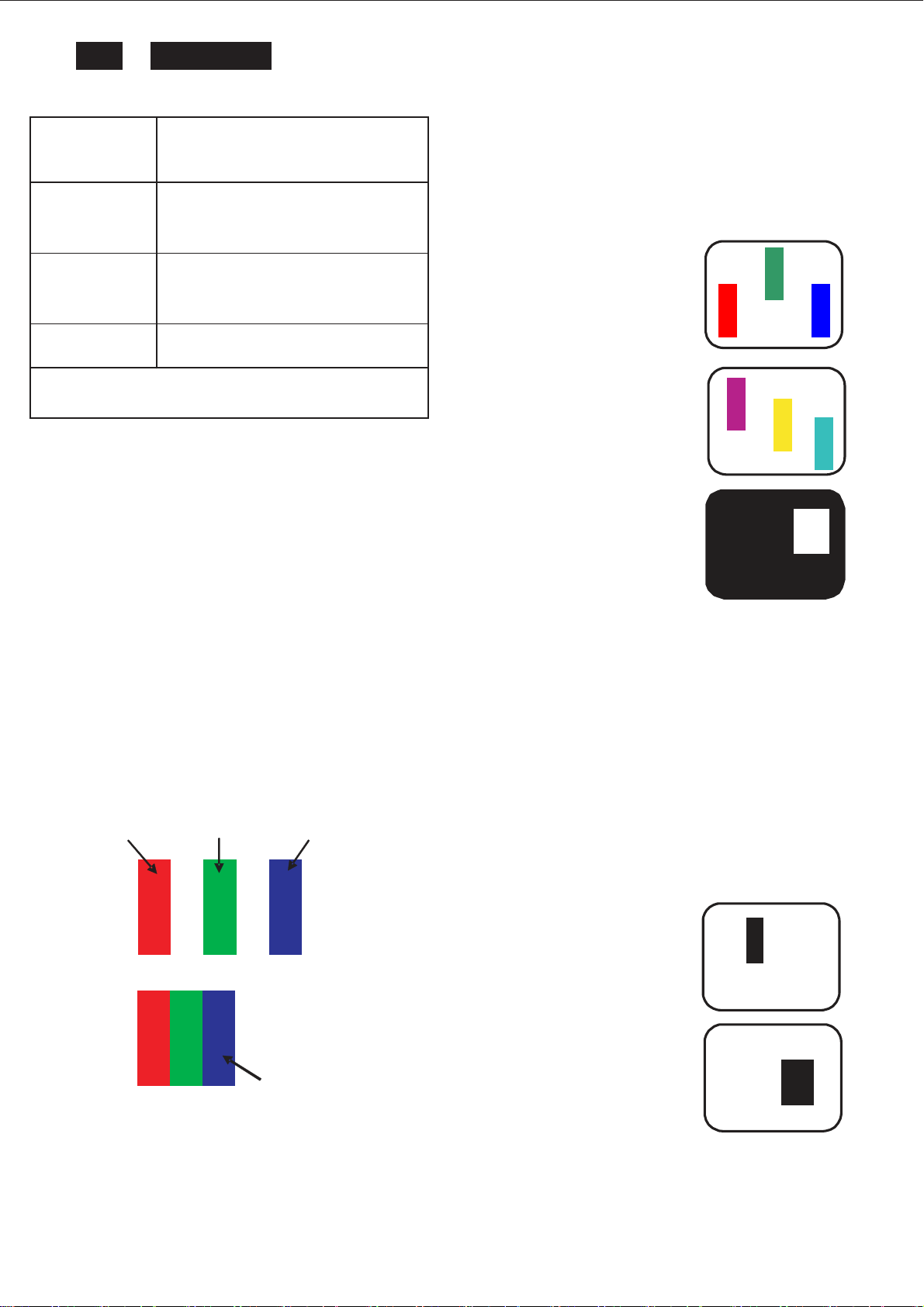
1. Definition of Pixels and Sub-pixels
A pixel, or picture element, is composed of three sub pixels in
the primary colors of red, green and blue. Many pixels
together form an image. When all sub pixels of a pixel are lit,
the three colored sub pixels together appear as a single white
pixel. When all are dark, the three colored sub pixels together
appear as a single black pixel. Other combinations of lit and
dark sub pixels appear as single pixels of other colors.
subpixel
subpixel
subpixel
R
G B
http://www.wjel.net
R G B
2. Types of Pixel Defects
Pixel and sub pixel defects appear on the screen in different
ways. There are two categories of pixel defects and several
types of sub pixel defects within each category.
Pixel
Bright Dot Defects
Bright dot defects appear as pixels or sub pixels that are
always lit or 'on'. That is, a bright dot is a sub-pixel that
stands out on the screen when the monitor displays a dark
pattern. There are the types of bright dot defects:
R
G
B
One lit red, green or blue sub pixel
Two adjacent lit sub pixels:
Red + Blue = Purple
Bule+Green = Yellow
Green + Blue = Cyan (Light Blue)
Three adjacent lit sub pixels
(one white pixel)
A red or blue bright dot must be more than 50
percent brighter than neighboring dots while a
green bright dot is 30 percent brighter than
neighboring dots.
Black Dot Defe cts
Black dot defects appear as pixels or sub pixels that are
always dark or 'off'. That is, a dark dot is a sub-pixel that
stands out on the screen when the monitor displays a light
pattern. These are the types of black dot defects:
P
Y
C
W
One dark sub pixel
Two or three adjacent
dark sub pixels
Definition of pixel defects
3. Proximity of Pixel Defects
Because pixel and sub pixels defects of the same type that
are near to one another may be more noticeable, Philips also
specifies tolerances for the proximity of pixel defects.
Perfect Panel - ISO 13406-2 Class II compliant do-defectfree-display.
BRIGHT DOT DEFECTS ACCEPTABLE LEVEL
MODEL 190EW9
1 lit subpixel 3
2 adjacent lit subpixels 1
3 adjacent lit subpixels (one white pixel) 0
Distance between two bright dot defects* 15mm
Bright dot defects within 20 mm circle 0
190EW9 LCD 11
Total bright dot defects of all types 3
BRIGHT DOT DEFECTS ACCEPTABLE LEVEL
MODEL 190EW9
1 dark subpixel 5
2 adjacent dark subpixels 2
3 adjacent dark subpixels (one white
pixel) 1
Distance between two dark dot defects* 15mm
Black dot defects within 20 mm circle 1
Total black dot defects of all types 5
TOTAL DOT DEFECTS
MODEL 190EW9
Total bright or black dot defects of all
types 5
ACCEPTABLE LEVEL
Note:
* 1 or 2 adjacent sub pixel defects = 1 dot defect
http://www.wjel.net
190EW9 LCD 12
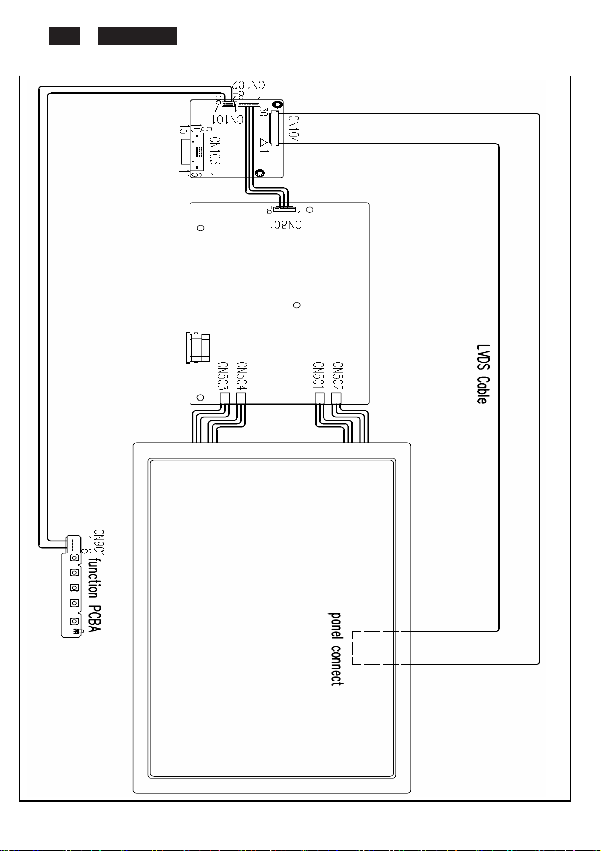
Wiring Diagram
http://www.wjel.net
Mechnical instructions
1. Press the release button, Than take off the
base.
2. Press the release button, Than take off the
stand down.
4..
190EW9 LCD 13
4.Reserve the Monitor then Panel come off.
Disconnect the tape and LVDS cable from
panel.
5.Tear off the tape from the lamp cable.
3. Take off the front bezel.
http://www.wjel.net
6.Disconnect the lamp cable from Power
board.
7.
Remove 2PCS attach VGA connect screw.
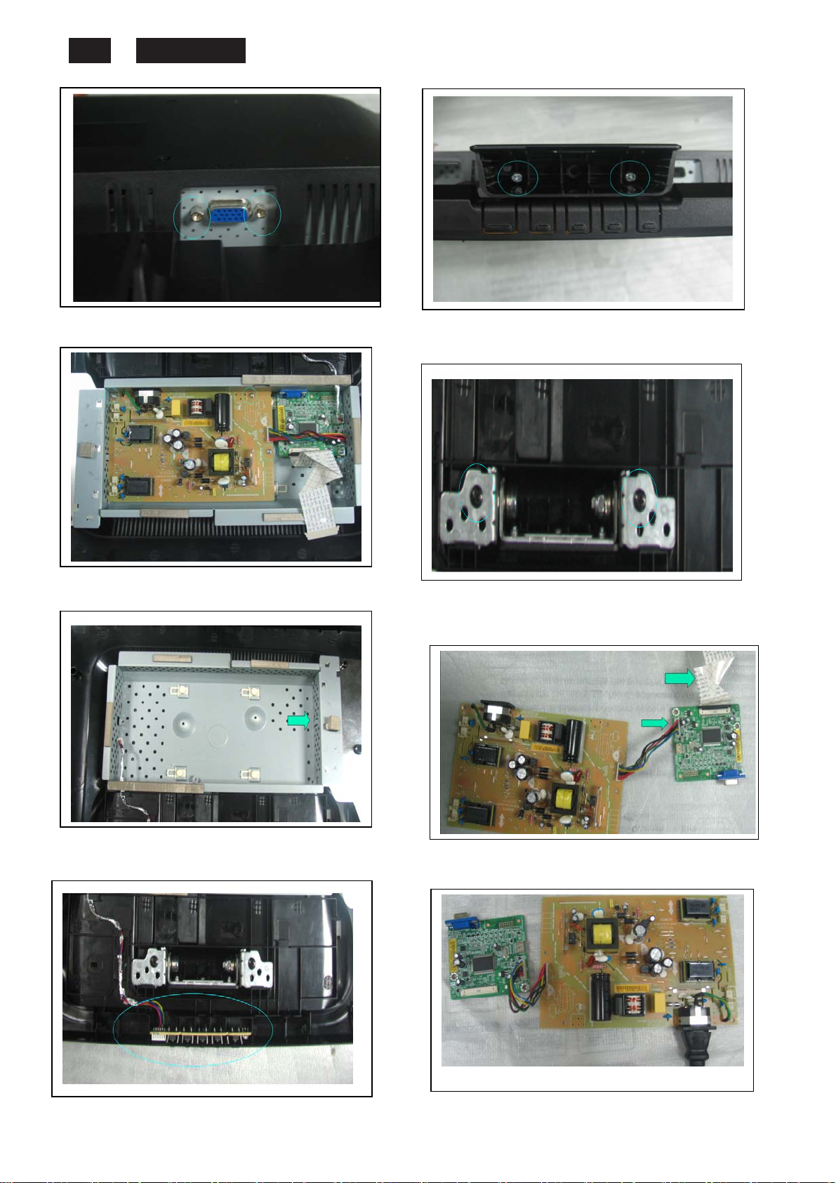
190EW9 LCD 14
8.Release 5pcs screw form P/B & IF/B.
9. Take off the chassis.
http://www.wjel.net
10. Take off the cable of function key.
11.Remove 2pcs screw from the join of stand
up& hinge , Than take off the stand up.
12.Remove 2pcs screw from the join of
hinge& backcover , Than take off the hinge.
13.Disconnect the connector and LVDS
from IF board.
14.Service position.
Electrical instructions
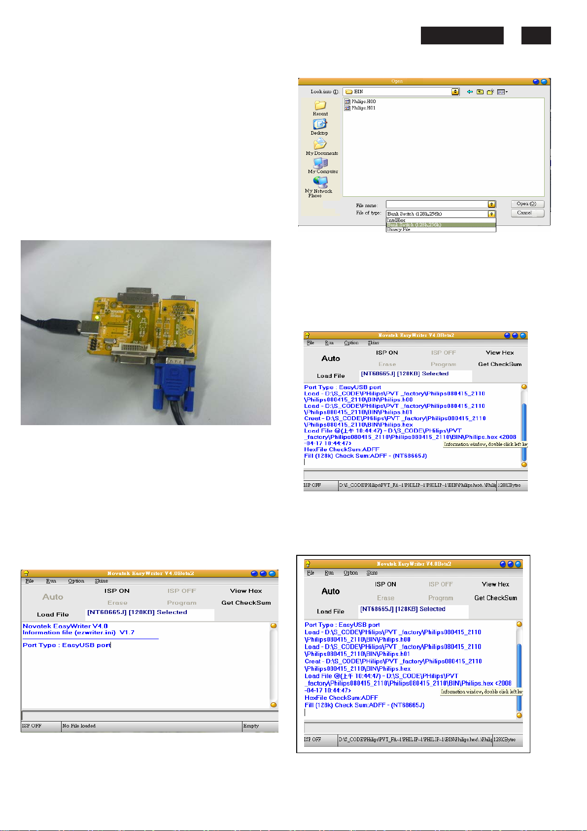
F/W upload instruction
Configuration and procedure (ISP Tool)
"ISP Tool" software is provided by NOVATEK to upgrade
the firmware of Scaler IC. It is a windows-based program,
which cannot be run in MS-DOS.
System and equipment requirements:
1. An i486 (or above) personal computer or compatible.
2. Microsoft operation system Windows 98/2000/XP.
3. ISP software " EasyUSB Writer V4.0 ".
(Need to install, it can not be performed directly.Double
press“EasyUSB Writer V4.0.exe”to start installing,then
chose the path that you want to install ,then it will perform
automatically.)
4. Firmware uploading tool, as shown in Fig1.
Fig1
* Connect the firmware uploading tool as Fig.1 shown.
* Before the servicer perform the ISP Tool program, the
Communicating connection must be well done.The USB
port connects to the computer. VGA port connects to the
Monitor
* When the connection fixed, power on the monitor.
Setup and perform the ISP Tool program
1. Save the software in your PC, and create a shortcut
on the desktop.
2. Double click the ISP Tool. exe icon at the desktop then
appears window as shown in Fig. 2.
.
http://www.wjel.net
Fig. 2
3. Press the “Load File”button then select the path that
save hex file , then chose file type as “Bank
Switch(128K,256K)”as shown:
190EW9 LCD 15
4. Double press the “H00” file or “H01 file” ,then it acquires
the hex file automatically, and a message will be showed in
the dialog box to notice the operator. At this moment,
please verify the checksum of the hex file with the firmware
control table to make sure the suitable file will be used.
Mentioned firmware control table will be provided by
suppliers shown in Fig. 4.
5. Press the “ISP ON” button ,then the dialog box will has the
information “ISP ON”,else has the information “ISP Fail”.If the
information is“ISP Fail ,check the connectivity ,then try it
again as shown in Fig. 5.
Fig3
Fig4
Fig. 5.
190EW9 LCD 16
DDC instructions
6. Press “Auto”button of the toolbox. Program will perform
the loading process automatically. When the loading
process completed, and the dialog box appeared the
message of Programing Success. If Program perform
fail ,resume step 5.
http://www.wjel.net
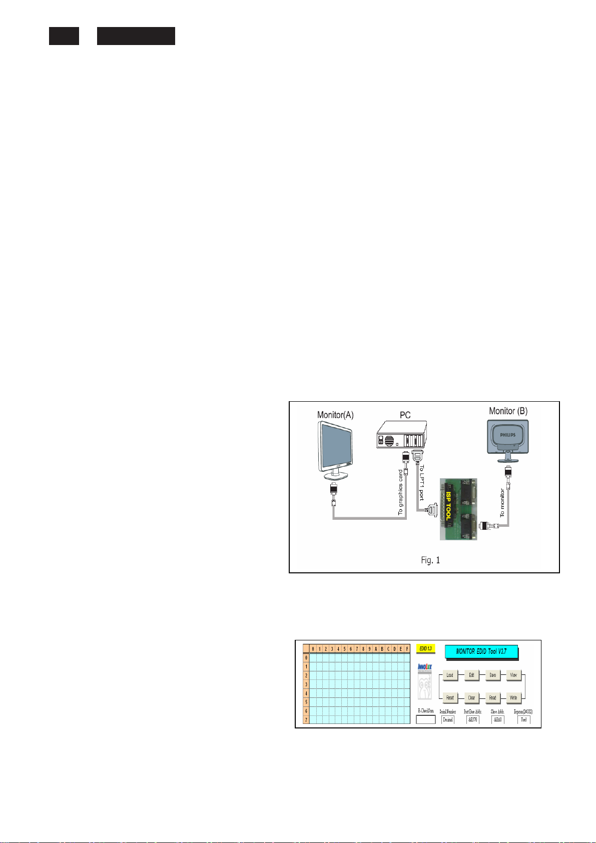
DDC Data Re-programming
In case the DDC data main EEPROM which
storage all factory settings were replaced due to a defect, the
serial numbers have to be re-programmed
It is advised to re-soldered DDC IC and main EEPROM from
the old board onto the new board if circuit board have been
replaced, in this case the DDC data does not need to be reprogrammed.
* According to the design concept of this product,
DDC data of VGA interface are saved in EEPROM(IC 24C02)
Additional information
Additional information about DDC (Display Data Channel) may
be obtained from Video Electronics Standards Association
(VESA). Extended Display Identification Data(EDID) information
may be also obtained from VESA.
System and equipment requirements
1. An i486 (or above) personal computer or compatible
2. Microsoft operation system Windows 98/2000/XP
3. Installation software of "EDID_Tool_3.7"
4. Executive program "EDID_Tool_3.7. exe "
5. ISP tool kit, as shown in Fig1
Connect the EDID tool as follow in Fig1: The parallel port
connects to the computer. VGA port connects to the Monitor.
Including: a. Alignment fixture x 1
b. Printer cable (LPT type) x 1
c. D-sub to D-sub cable x 1
Fig 1
Install and setup EDID_Tool_3.7 program
Step 1: Double press the “EDID_Tool_3.7.exe”,as follow:
Step 2: The EDID Tool Install finished.
Fig 2
http://www.wjel.net
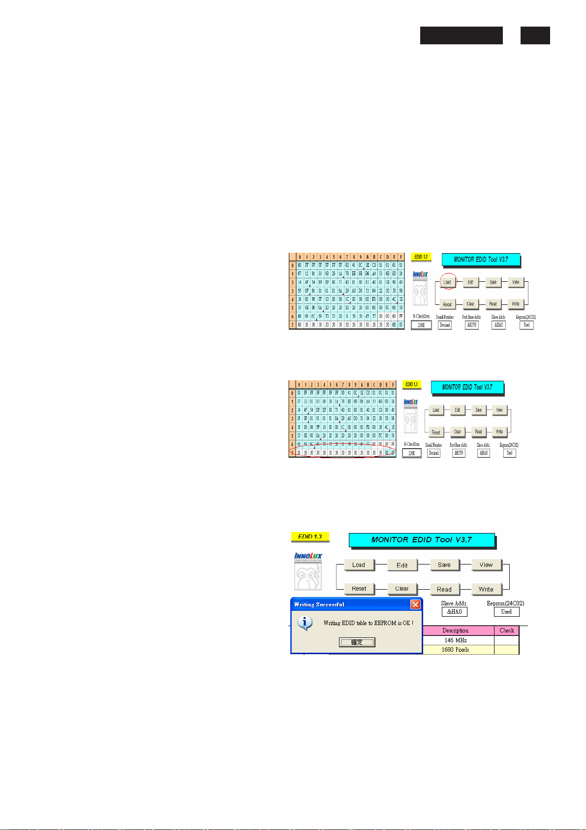
Re-programming Analog DDC IC
Step 1: After initialize the alignment fixture, connecting
Step 2: Connect the power code of monitor and power on it.
Step 3: Double check the
Step 4: Click the LOAD icon at the main
Fig 4
Step 5: In the “Detailed Timings”, key in the monitor serial
number.
Fig 5
Step 6: Press “Write” button in the tool main ,when the
DDC data download into the monitor, the message will be
appeared automatically as shown in below photos.
Fig 6
190EW9 LCD 17
all cables. Be using VGA port from monitor.
EDID_Tool_3.7 icon to run the
EDID_Tool_3.7.exe.
menu to open the DDC files, load
the files into EDID Tool, The EDID
table will be appeared automatically
as shown in below photos.
190EW9 LCD 18
DDC Data
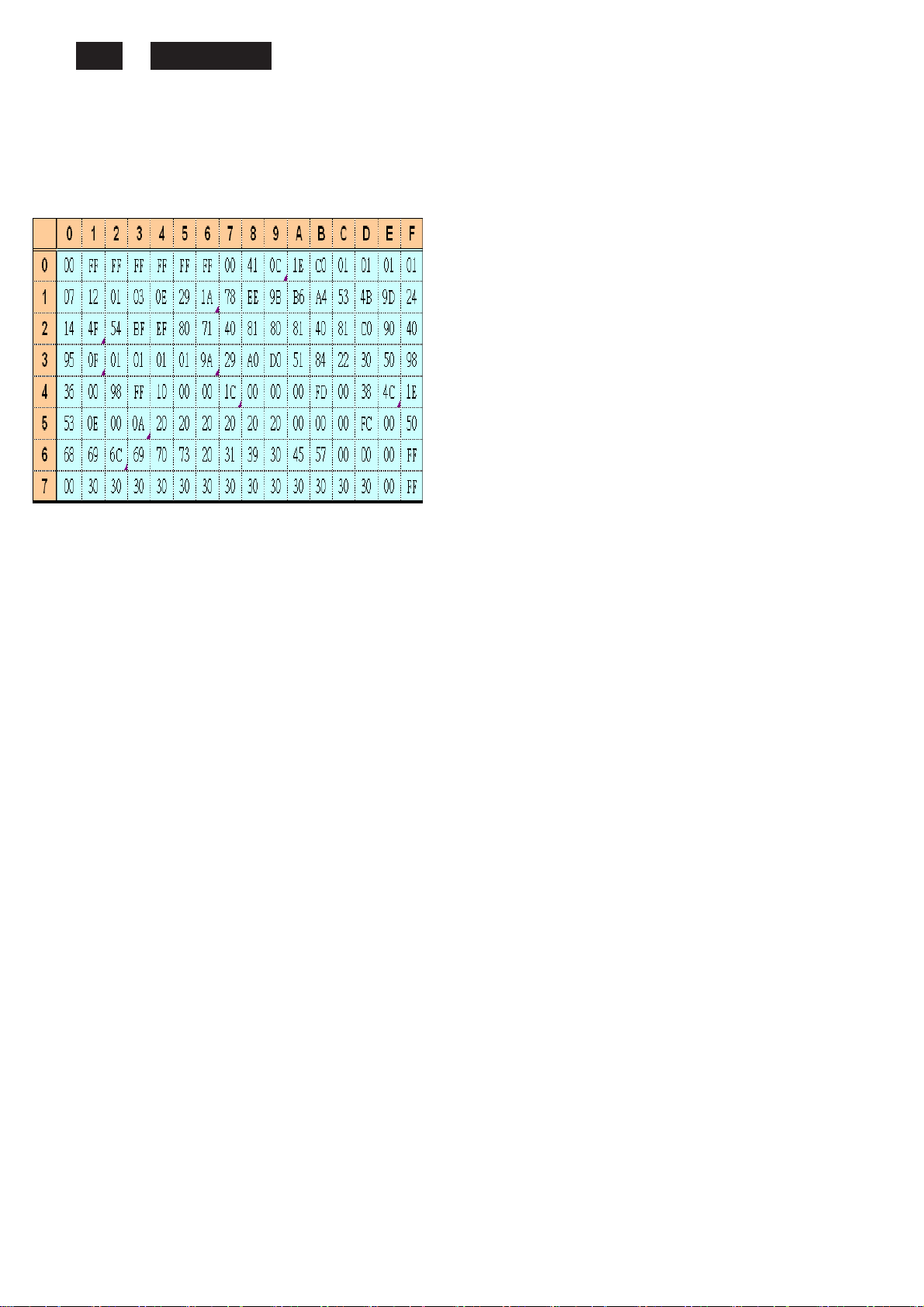
THE DISPLAY DATA CHANNEL (DDC_2B) CONTENT INCLUDING:
(Analog mode)
128 BYTES OF EDID CODE :
(08~09h) ID Manufacturer Name=PHL
(0A~0Bh) Product ID Code= C01E
(0C~0Fh) Last 5 Digits of Serial Number= NOT SPECIFIED
(10h) Week of Manufacture=Product date
(11h) Year of Manufacture= Product date
(12h) EDID Version Number=1
(13h) EDID Revision Number=3
(14h) Video Input Definition: 0E
Analog Signal Level
0.700, 0.300 (1.000Vp-p)
No Blank -to-black Setup
Separate Syncs. Supported
Composite Sync. Supported
Sync. on Green Supported
No Serration Required
(15h) Max Horizontal Image Size=41 cm
(16h) Max Vertical Image Size=26 cm
(17h) Display Gamma=2.2
(18h) Power Management and Supported Feature(s): EE
Standby
Suspend
(19~22h) Chroma Info=
(23h) Established Timing I:
http://www.wjel.net
Active Off/Very Low Power
RGB Color Display
sRGB Color Space
Preferred Timing Mode
No Default GTF Supported
R (x, y) 0.643, 0.325
G (x, y) 0.295, 0.616
B (x, y) 0.143, 0.081
w (x, y) 0.310, 0.330
720 x 400 @ 70Hz
720 x 400 @ 88Hz (N/A)
640 x 480 @ 60Hz
640 x 480 @ 67Hz
640 x 480 @ 72Hz
640 x 480 @ 75Hz
800 x 600 @ 56Hz
800 x 600 @ 60Hz
(24h) Established Timing II:
800 x 600 @ 72Hz
800 x 600 @ 75Hz
832 x 624 @ 75Hz
1024 x 768 @ 87Hz(I) (N/A)
1024 x 768 @ 60Hz
1024 x 768 @ 70Hz
1024 x 768 @ 75Hz
1280 x 1024 @ 75Hz
(25h) Manufacturers Reserved Timings:
(26~35h) Standard Timing Identification
(36~47h) Detailed Timing / Descriptor Block 1
(5A~6Bh) Detailed Timing / Descriptor Block 2
Monitor Name: Philips 190EW
(48~59h) Detailed Timing / Descriptor Block 3
(6C~7Dh) Detailed Timing / Descriptor Block 4
Monitor Serial Number: Product provide
(7Eh) Extension flag 00
(7Fh) Checksum =OK
1152 x 870 @ 75Hz
800 x 600 @ 85Hz (N/A)
1024 x 768 @ 85Hz (N/A)
1280 x 1024 @ 60Hz (N/A)
1280 x 1024 @ 85Hz (N/A)
1600 x 1024 @ 60Hz (N/A)
1600 x 1200 @ 75Hz (N/A)
1600 x 1200 @ 85Hz (N/A)
1152 x 864 @ 60Hz 4: 3
1280 x 1024 @ 60Hz 5: 4
1280 x 960 @ 60Hz 4:3
1280 x 720 @ 60Hz 16:9
1400 x 1050@60Hz 4:3
1440 x 900@75Hz 16:10
No Application
No Application
1440x900 @ 60Hz 106.5 MHz
Min. Vertical Frequency: 56 Hz
Max. Vertical Frequency: 76 Hz
Min. Horizontal Frequency: 30 KHz
Max. Horizontal Frequency: 83 KHz
Max. Pixel Clock: 140 MHz
Satety instruction,warnings and notes
index of this chapter:
1 Safety Instructions
2 Warnings
3 Notes
1 Safety Instructions
Safety regulations require that during a repair:
a. Connect the set to the AC Power via an isolation transformer
(> 800 VA).
b. Replace safety components, indicated by the symbol
only
other component substitution (other than original type)
may increase risk of fire or electrical shock hazard.
by
components identical to the original ones. Any
Safety regulations require that after a repair, the set must
be returned in its original condition. Pay in particular
attention to the following points:
a. Route the wire trees correctly and fix them with the
mounted cable clamps.
b. Check the insulation of the AC Power lead for
external damage.
c. Check the strain relief of the AC Power cord for
proper function.
d. Check the electrical DC resistance between the AC Power
plug
and the secondary side (only for sets which have a
AC Power isolated power supply):
* Unplug the AC Power cord and connect a wire between
the two pins of the AC Power plug.
* Set the AC Power switch to the "on" position (keep the
AC Power cord unplugged!).
* Measure the resistance value between the pins of the AC
Power
plug and the metal shielding of the tuner or the
aerial connection on the set. The reading should be
between 4.5
Mohm and 12 Mohm.
* Switch "off" the set, and remove the wire between the two
Pins of the AC Power plug.
e. Check the cabinet for defects, to avoid touching of any
inner parts by the customer.
2 Warnings
a. All ICs and many other semiconductors are susceptible to
electrostatic
during repair can reduce life drastically. Make sure that,
during repair,
you are connected with the same potential as the mass of
the set by a wristband with resistance. Keep components
and tools also at this same potential.
b. Be careful during measurements in the high voltage section.
c.
Never replace modules or other components while the unit
is switched "on".
d. When you align the set, use plastic rather than metal tools.
This
circuit becoming unstable.
discharges (ESD
will prevent any short circuits and the danger of a
3 Notes
3.1 General
Measure the voltages and waveforms with regard to the
chassis
of circuitry. The voltages and waveforms shown in the
diagrams are indicative.
The semiconductors indicated in the circuit diagram and in the
parts
semiconductors
on
ground or hot ground, depending on the tested area
lists, are interchangeable per position with the
in
).
http://www.wjel.net
the unit, irrespective of the type indication
Careless handling
3.2 Schematic Notes
All resistor values are in ohms and the value multiplier is often
used
2.2 Kohm).
Resistor values with no multiplier may be indicated with either
an
All capacitor values are given in micro-farads ( X10-6),
,
nano-farads
Capacitor values may also use the value multiplier as the
decimal
An "asterisk" (*) indicates component usage varies. Refer to the
diversity
The correct component values are listed in the Electrical
Replacement
there
3.3 Lead Free Solder
Philips CE is going to produce lead-free sets (PBF) from
1.1.2005 onwards.
Lead-free sets will be indicated by the PHILIPS-lead-free logo
on
This sign normally has a diameter of 6 mm, but if there is less
space
In case of doubt wether the board is lead-free or not (or with
mixed
Caution: For BGA-ICs, you must use the correct temperature
profile, which is coupled to the 12NC. For an overview of these
profiles,
Yo u will find this and more technical information within the
"Magazine", chapter "Workshop information".
For additional questions please contact your local repair desk.
Due
by
Use only lead-free soldering tin Philips SAC305 with order code
0622 149 00106. If lead-free solder paste is required, please
contact
In general, use of solder paste within workshops should be
avoided
Use only adequate solder tools applicable for lead-free
soldering
190EW9 LCD 19
to
indicate the decimal point location (e.g. 2K2 indicates
"E" or an "R" (e.g. 220E or 220R indicates 220 ohm).
(n= X10-9), or pico-farads (p= X10
point indication (e.g. 2p2 indicates 2.2 pF).
tables for the correct values.
Parts List. Therefore, always check this list when
is
any doubt.
the Printed Wiring Boards (PWB):
on a
technologies), you can use the following method:
* Always use the highest temperature to solder, when using
SAC305 (see also instructions below).
* De-solder thoroughly (clean solder joints to avoid mix of
two
alloys).
visit the website
to
lead-free technology some rules have to be respected
the workshop during a repair:
the manufacturer of your soldering equipment.
because paste is not easy to store and to handle.
tin. The solder tool must be able
- To reach at least a solder-tip temperature of 400 degree C.
- To stabilise the adjusted temperature at the solder-tip.
- To exchange solder-tips for different applications.
board also 3 mm is possible.
http://www.atyourservice.ce.philips.com/
-12
).
 Loading...