

Philips 190CW9FB/69, 190CW9FB/00, 190CW9FB/97, 190CW9FB/75, 190CW9FB/93 Service Manual
19 inch TFT WXGA LCD Colour Monitor
190CW9FB/69
190CW9FB/00
190CW9FB/75
190CW9FB/93
190CW9FB/97
Chassis: HUDSON 9
TABLE OF CONTENTS
Description Page
Important Safety Notice-------------------------------------2
Technical Data--------------------------------------------- 3~4
Installation------------------------------------------------------5
Troubleshooting-----------------------------------------------6
On Screen Display-----------------------------------------7~8
Lock/unlock, Aging,Factory mode-------------------------9
Philips Pixel Defect Policy
Mechanical Instructions -----------------------------11~12
Color adjustment -------------------------------------------13
FAQs (Frequently Asked Questions)--------------14~15
Electrical instruction ---------------------------------16~17
DDC Instructions & Serial Number ----------------18~24
DDC DATA ----------------------------------------------25~26
Firmware Upgrade for CPU-
Failure Mode Of Panel -
ANY PERSON
AND BE AW ARE OF THE NECESSARY SAFETY PRECAUTIONS
EQUIPMENT CONTAINING
---------------------------------10
------------------------27~28
----------------------------------29
SAFETY NOTICE
ATTEMPTING TOSERVICE THIS CHASSIS
HIGH VOLTAGES.
Horizontal frequencies
Description Page
Wiring Diagram--------------------------------------------30
Block Diagram----------------------------------------------31
Scaler Diagram & C.B.A. ----------------------------32~38
Power Diagram & C.B.A. ---------------------------39~42
Control Diagram & C.B.A. ---------------------------43~44
LED Diagram & C.B.A. ---------------------------45~46
USB Diagram & C.B.A. ---------------------------47~50
General product specification----------------------51~79
Exploded View ---------------------------------------------80
Spare/ arts List----------------------81
Recommended P
PCBA photos------------------------------------------------82
Repair tips----------------------------------------------83~84
Repair Flow chart-------------------------------------85~87
Safety Test Requirments---------------------------------88
MUST FAMILIARIZE
TO BE USED WHEN
WITH THE
HIMSELF
SERVICING ELECTRONIC
30-83kHz
CHASSIS
http://www.wjel.net
CAUTION:
Published by Philips Consumer Lifestyle Copyright reserved Subject to modification JJul 3 2008
A SEPARATE
USE
REFERTO BACK COVER FOR
ISOLATION TRANSFORMER FOR THIS UNIT WHEN SERVICING.
IMPORTANT SAFETY GUIDELINES
GB
312278518150

190CW9 LCD
2
2
220
BW8 LCD
Important Safety Notice
Proper s ervic e and repair is important
operation of all Philips Consumer Electronics Co
commended by
equipment. The service procedures
described in this service manual a
performing service ope
operations require the useof tools speciall y desi gned
purpose. The spe
recomm ended.
It is im portant to note that this m anual c ontains various
CAUTI ON
order to m inimize the risk of personal injury to servic
personnel . The possibility exists th
methods may damage the equipment
underst and that these CAUTIONS and NOTICES ARE NOT
EXHAUSTIVE. Phil
advise the servic etrade of all conceivable ways i n w
service might be done or of the possible hazardous
consequences of each way. Consequently,Philips has not
undertaken any suc
who uses a servi ce procedure or tool which is not
recommended by Philipsmust f
neither his saf ety nor the safeoperation of the equipment will
be jeopardized by the servi
* * Hereafter throughout this manu
Electronics Company w
S and NOTICES which should be
rations
cial tools should be used w
ips
could not possibly know, evaluate and
h broad evalua
be referred to as Philip
ill
re
re eff
.Someof
at im
. It is also important t
ti
on. Accordingly
irst sati
ce method sel
al,
PhilipsConsumer
fe,
to the sa
ect
these servic
carefully read in
proper
sfy
ect ed.
reliable
mpany
Phil
servi
s
sof
e
for the
e
ce
h
hic
,
**
.
ive method
hen and as
himself thoroughly that
ips and
o
FOR PRODUCTS CONTAINING LASER :
DANGER - Invisible laser radiation when open.
MANUF
O BEAM.
in
OF THIS
ACTURER'S
THIS
AVOID DIRECT EXPOSURE T
CAUTION - Use of controls or adjustments or
performance of procedures other than
those specified herein may result
hazardous radiation exposure.
CAUTION - The use of optical instruments with this
product will increase eye hazard.
TO ENSURE THE CONTINUED RELIABILITY
PRODUCT, USE ONLYORIGINAL
REPLACEMENT PAR TS, WHICH ARE LISTED WITH THEIR P
NUMBERS IN THE PAR
SERVICE MANUAL.
TS LIST SECTION OF
ART
WARNING
Critical components havingspecial safety characteristics are
identified with a by the Ref. No. in the parts list and
enclosed within a broken line
(where several critical co
along with the safe
exploded vie
Use of substitute replacement parts which do no
same speci fied safety charact eristic s may create
or other hazards .
Under no circumstances should th
modified or altered without written permission from Philip
Philips assumes no liabilit
any unauthorized modification of design.
Servicer assumes all liability.
ws.
mponents are grouped in
mbol on the schematics
y
ty s
http://www.wjel.net
e original
y, express or implied, arising
one area)
or
t have the
shock,
design be
fi
out of
re,
Take care during handling the LCD module with backlight
unit
- Must mount the module using mounting holes arranged in four
corners.
- Do not press on the panel, edge of the frame strongly or electric
shock as this will result in damage to the screen.
- Do not scratch or press on the panel with any sharp objects, such
as pencil or pen as this may result in damage to the panel.
- Protect the module from the ESD as it may damage the electronic
circuit (C -MOS).
Make certain that treatment body are grounded through
-
wrist band.
- Do not leave the
humidity for a long time.
s.
- Avoid contact with water as it may as hort circuit within the module.
If the surface of panel become dirty
-
material. (Cleaning with a dirty or rough cloth may damage the
panel.)
module in high temperature and
, please wi
pe it off with a soft
in areas of high
Technical Data
SEC panel
Type NR. : SEC, LTM190M2-L31
Outside dimensions : 428 (H) x 278(V) x 17(D) mm (Typ.)
Pitch (mm) : 0.2835(H) x 0.2835(V) mm
Color pixel arrangement : RGB vertical stripes
Display s urface : Hard c oating (3H ), Anti-glare treatment of
Color depth : 16.7M c olors
Backlight : CCFL edge light system
Active area ( W xH ) : 408.24 (H) x 255.15 (V)
View angle : R/L 160(Typ.), U/D 160(Typ.)
Contrast ratio : 1000:1(Typ.) 600:1(Min.)
White luminance : Original color 250 nits (Min), 300 nits (Typ.)
Gate IC : OKI MT3805VA
Source IC : MAGNA D10D3SS639
Respons e time : 5ms (typ)
Scanning frequencies
Hor. : 30 – 83 K Hz
Ver. : 5 6 - 76 Hz
Video dot rate : <140 MHz
Power input : 90-264 V AC, 50/60 ± 2Hz
Power c onsumption : < 36W ( Typ.)
Functions:
(1)D-SUB analog R/G /B separate inputs, H/V s ync s eparated, Composite
(H+V) TTL level, SOG sync
(2) DVI digital Panel Link TMDS inputs
Ambient temperature: 0 °C-40°C
Power input connection
Power c ord length : 1.8 M
Power c ord type : 3 leads power cord with protective earth plug.
Power management (supplier to input)
The monitor must comply with the Microsoft On Now specification, and
meet EPA requirements.
Mode HSYNC VSYNC Video Pwr-cons. Indication Rec
Power-On On On active < 36 W
the front polarizer
<TBD W (Max.)
.time
Blue LED --
TBDW max.
190CW9 LCD 3
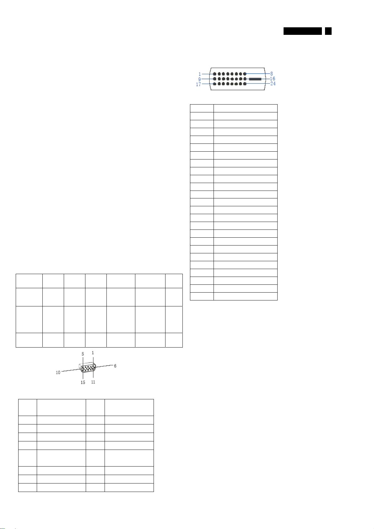
Pin No. Description
1 T.M.D.S. data2-
2 T.M.D.S. data2+
3 T.M.D.S. data2 shield
4 No Connect
5 No Connect
6 DDC clock
7 DDC data
8 No Connect
9 T.M.D.S. data1-
10 T.M.D.S. data1+
11 T.M.D.S. data1 shield
12 No Connect
13 No Connect
14 +5V Power
15 Ground (for +5V)
16 Hot plug detect
17 T.M.D.S. data0-
18 T.M.D.S. data0+
19 T.M.D.S. data0 shield
20 No Connect
21 No Connect
22 T.M.D.S clock shield
23 T.M.D.S. clock+
24 T.M.D.S. clock-
Off Off Off blanked < 0.8 W Blinking Blue
LED Period:
3sec On,
3sec Off
DC Power
Off
N/A < 0.8 W LED Off
http://www.wjel.net
PIN
SIGNAL PIN
No.
1Red 9DDC+3.3Vor+5V
2 Green/ SOG 10 Logic GND
3 Blue 11 Sense (GND)
4 Sense (GND) 12 Bi-directional data
5CableDetect
(GND)
6RedGND 14V-sync
7 Green GND 15 D ata clock
8BlueGND
Input DVI-D connector pin
SIGNAL
No.
13 H/H+V sync
<3s
Susceptibility of display to external environment
Operating
- Temperature : 0 to 40 degree C
- Humidity : 80% max
- Altitude : 0-3658m
- Air pressure : 600-1100 mBAR
Storage
- Temperature : -20 to 60 degree C
- Humidity : 95% max
- Altitude : 0-12192m
- Air pressure : 300-1100 mBAR
Note: recommend at 5 to 35°C, Humidity less than 60 %
4 190CW9 LCD
Technical Data
BOE panel
Type NR. : BOE, HT190WG1
Outside dimensions : 427.2(w)∗277.4(h)∗17.0(d) (Typ) mm
Pitch ( mm ) : 0.285 mm x 0.285 mm
Color pixel arrangement : RGB vertical stripes
Display s urface : low reflection, antiglare with hard coating
Color depth : 16.7M colors ( 6 bits+FRC )
Backlight : CCFL edge light system
Active area (W xH) : 408.24 x 255.15mm (19.05” diagonal)
View angle (CR>10) : 70/70 ( min), 85/85 (typ) for Horizontal &
Contrast ratio : 1000:1(Typ.) 700:1(Min.)
White luminance : Original color 230 nits (Min), 300 nits (Typ.)
Gate IC : Novatek NT39613H-C1221A ,
Source IC : Novatek NT39338H-C1217C
Response time : 5ms (typ)
Scanning frequencies
Hor. : 30 – 83 K Hz
Ver. : 5 6 - 76 Hz
Video dot rate : <140 MHz
Power input : 90-264 V AC, 50/60 ± 2Hz
Power c onsumption : < 36W ( Typ.)
Functions:
(1)D-SUB analog R/G /B separate inputs, H/V s ync s eparated, Composite
(H+V) TTL level, SOG sync
(2) DVI digital Panel Link TMDS inputs
Ambient temperature: 0 °C-40°C
Power input connection
Power c ord length : 1.8 M
Power c ord type : 3 leads power cord with protective earth plug.
Power management (supplier to input)
The monitor must comply with the Microsoft On Now specification, and
meet EPA requirements.
Mode HSYNC VSYNC Video Pwr-cons. Indication Rec
Power-On On On active < 36 W
70/70 (min), 80/80 (typ) for Vertical
<TBD W (Max.)
.time
Blue LED --
TBDW max.
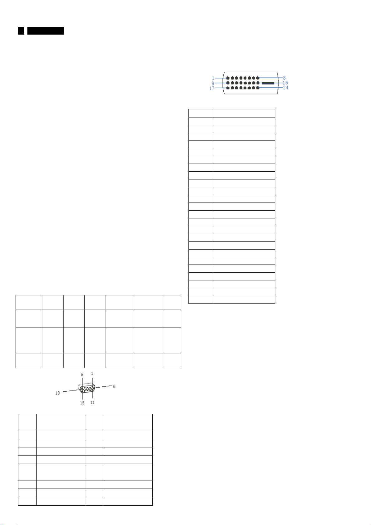
Pin No. Description
1 T.M.D.S. data2-
2 T.M.D.S. data2+
3 T.M.D.S. data2 shield
4 No Connect
5 No Connect
6 DDC clock
7 DDC data
8 No Connect
9 T.M.D.S. data1-
10 T.M.D.S. data1+
11 T.M.D.S. data1 shield
12 No Connect
13 No Connect
14 +5V Power
15 Ground (for +5V)
16 Hot plug detect
17 T.M.D.S. data0-
18 T.M.D.S. data0+
19 T.M.D.S. data0 shield
20 No Connect
21 No Connect
22 T.M.D.S clock shield
23 T.M.D.S. clock+
24 T.M.D.S. clock-
Susceptibility of display to external environment
Off Off Off blanked < 0.8 W Blinking Blue
DC Power
Off
N/A < 0.8 W LED Off
LED Period:
3sec On,
3sec Off
http://www.wjel.net
PIN
SIGNAL PIN
No.
1Red 9DDC+3.3Vor+5V
2 Green/ SOG 10 Logic GND
3 Blue 11 Sense (GND)
4 Sense (GND) 12 Bi-directional data
5CableDetect
(GND)
6RedGND 14V-sync
7 Green GND 15 D ata clock
8BlueGND
Input DVI-D connector pin
SIGNAL
No.
13 H/H+V sync
<3s
Operating
- Temperature : 0 to 40 degree C
- Humidity : 80% max
- Altitude : 0-3658m
- Air pressure : 600-1100 mBAR
Storage
- Temperature : -20 to 60 degree C
- Humidity : 95% max
- Altitude : 0-12192m
- Air pressure : 300-1100 mBAR
Note: recommend at 5 to 35°C, Humidity less than 60 %
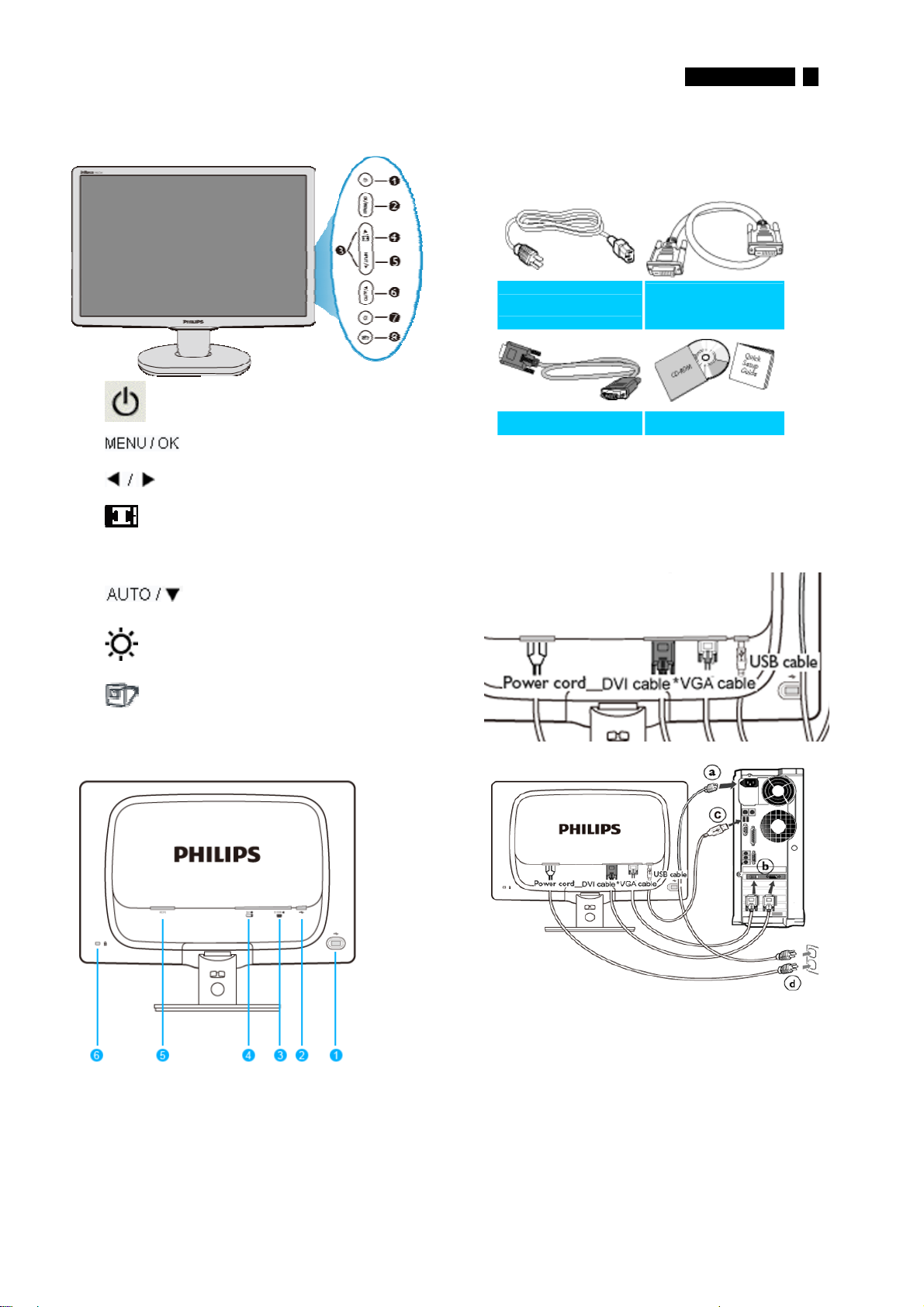
Front View Product Description
190CW9 LCD 5
Installation
Accessory Pack
Unpack all the parts
1 To switch monitor's power On and Off
2
3
4 Change to 4:3 display
5 Input To change the signal input source
6
7
8
To access the OSD menu
To adjust the OSD menu
Automatically adjust the horizontal
position, vertic al position, phase and
clock settings / Return to pr evious
OSD level
To adjust brightness of the display
SmartImage. There ar e five modes to
be selected: Office Work, Image
Viewing, Entertainment, Ec onomy,
and Off
Power cord
ʳ
DVI cable
(Optional)
ʳ
VGA cable
ʳ
EDFU pack
ʳ
Connecting to Your PC
1) Connect the power cord to the back of the
monitor firmly. (Philips has pre-connected VGA
cable for the first installation
ʳ
ʳ
Rear View
1
ʳ
2
ʳ
3
ʳ
4
ʳ
5
ʳ
6
ʳ
http://www.wjel.net
USB downstream port
USB upstream port
VGA input
DVI-D input (available for selective models)
AC power input
Kensington anti-thief lock
ʳ
ʳ
ʳ
ʳ
ʳ
2) Connect to PC
(a)ʳTurn off your computer and unplug its power cable
(b) Connect the monitor signal cable to the
video connector on the back of your computer.
(c)
ʳ
Connect the USB cable to the USB port of your computer
(d) Plug the power cord of your computer and your monitor
ʳ
into a nearby outlet.
(e) Turn on your computer and monitor. If the monitor
displays an image, installation is complete
ʳ
6
190CW9 LCD
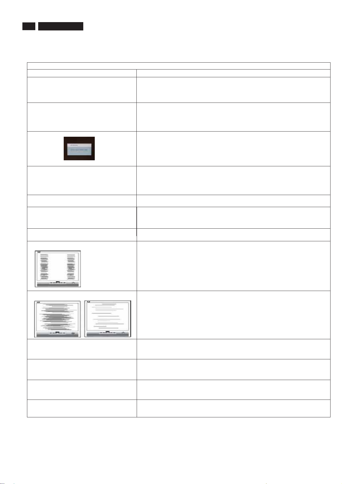
This page deals with problems that can be corrected by a user . If the problem still persists after you have tried thesesolutions, contact Philips
customer service representative.
Common Problems
Having this problem
No Picture
(Power LED not lit)
No Picture
(Power LED is amber or yellow)
Trouble shooting
Check these items
1.Make sure the power cord is plugged into the power outlet and into the back of the
monitor.
2.First, ensure that the power button on the front of the monitor is in the OFF position,
then press it to the ON position.
1.Make sure the computer is turned on.
2. Make sure the signal cable is properly connected to your computer.
3.Check to see if the monitor cable has bent pins.
4.The Energy Saving feature may be activated
Screen says
AUT O button not working properly
Imaging Problems
Display position is incorrect
Image vibrates on the screen
Vertical flicker appears
Horizontal flicker appears
1. Make sure the monitor cable is properly connected to your computer. (Also refer
to the Quick Set-Up Guide).
2.Check to see if the monitor cable has bent pins.
3. Make sure the computer is turned on.
1.The Auto Function is designed for use on standard Macintosh or IBM-compatible
PCs running Microsoft Windows.
2. It may not work properly if using nonstandard PC or video card.
1.Press the Auto button.
2. Adjust the image position using the Horizontal Position and/or V ertical
Position in OSD Main Controls.
Check that the signal cable is properly connected to the graphics board or PC.
1. Press the Auto button.
2. Eliminate the vertical bars using the More Settings of Phase/Clock in OSD Main
Controls.
1. Press the Auto button.
2. Eliminate the vertical bars using the More Settings of Phase/Clock in OSD Main
Controls.
The screen is too bright or too dark
http://www.wjel.net
An after-image appears
An after-image remains after the power
has been turned off.
Green, red, blue, dark, and white dots
Remains
Adjust the contrast and brightness on OSD Main Controls. (The backlight of the
LCD monitor has a fixed life span. When the screen becomes dark or begins to
flicker, please contact your dealer).
If an image remains on the screen for an extended period of time, it may be
imprinted in the screen and leave an afterimage. This usually disappears after a
few hours.
This is characteristic of liquid crystal and is not caused by a malfunction or
deterioration of the liquid crystal. The after-image will disappear after a peroid
of time.
The remaining dots are normal characteristic of the liquid crystal used in
today's technology.

190CW9 LCD 7
On Screen Display
Description of the On Screen Display
What is the On-Screen Display?
On-Screen Display (OSD) is a feature in all Philips LCD monitors. It allows an end user to adjust screen
performance or select functions of the monitors directly through an on-screen instruction window. A user
friendly on screen display interface is shown as below :
Basic and simple instruction on the control keys.
In the OSD shown above users can press buttons at the front bezel of the monitor to move the
cursor,
to confirm the choice or change.
http://www.wjel.net
8 190CW9 LCD
On Screen Display
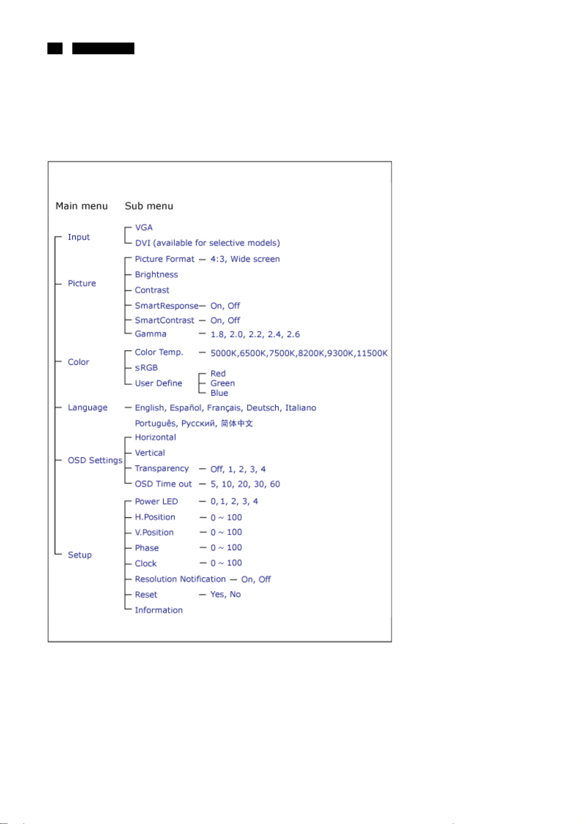
The OSD Tree
Below is an overall view of the structure of the On-Screen Display. You can use this as a
reference when you want to work your way around the different adjustments later on.
http://www.wjel.net
Resolution notification
This monitor is designed for optimal performance at its native resolution, 1440x900@60Hz.
When the monitor is powered on at a different resolution, an alert is displayed on screen:
Use 1440x900@60Hz for best results.
Display of the native resolution alert can be switched off from Setup in the OSD (On Screen
Display) menu.
Lock/Unlock,Aging,Factory Mode
190CW9 LCD
9
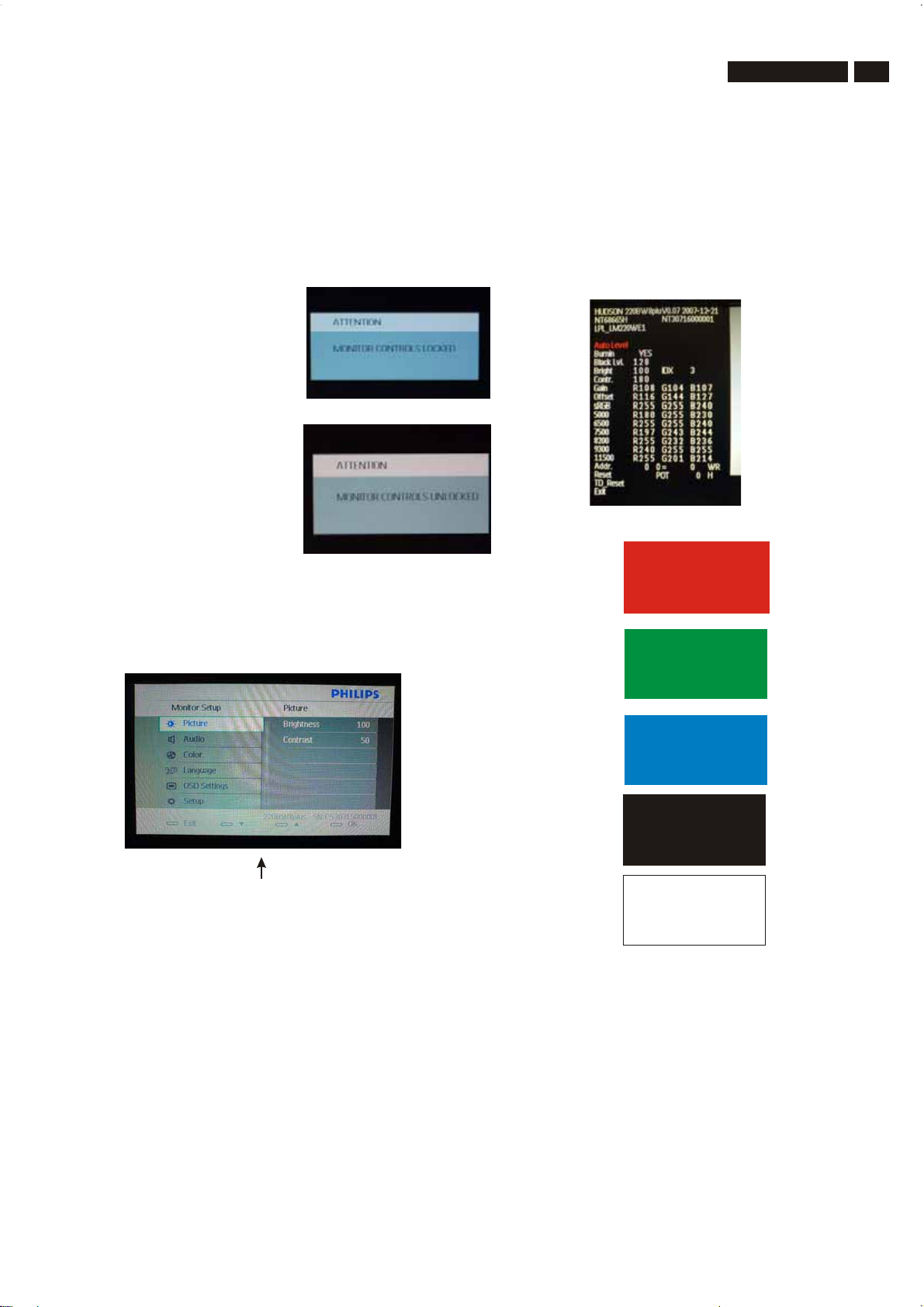
To Lock/Unlock OSD FUNCTION(User Mode)
The OSD function can be locked by pressing"OK"button(1) for more
than 10 seconds, the screen shows following windows for 4 seconds.
Every time when you press"OK" button, this message
appears on the screen automatically .
Unlock OSD function
Unlocked OSD function can be released by pressing "OK" button for
more than 10 seconds again.
Access Factory Mode
1). Turn off monitor.
[Push "AUTO" & "MENU" buttons at the same time and hold them]
2).
+[Press "power" button until comes out "Windows screen" ]
=> then release all buttons
3).Press "MENU" button, wait until the OSD menu with
Characters "HUDSON 220SW8 V0.07 2007-12-21 (below OSD
menu) come on the Screen of the monitor.
"
Access Aging Mode
Step 1 : Access Factory Mode then enter Factory Menu.
Step2:Bypressing
MENU then press key to turn on Aging Mode.
"" "
Step 3 : Disconnect interface cable between Monitor and PC.
After 3 seconds,
bring up:
"UP
"UP
" and " DOWN
" and " DOWN
key to Burning Icon. Press
"
Factory Mode indicator
Factory Menu
Cursor can move on gray color area
Hot key function: by pressing " UP " and " DOWN " key
Simultaneously at User Mode (or Factory Mode)
(PS: The Of fset R G B function can be used on reduce or eliminate
snowy noise on the background when the resolution of video signal
is 1680*1050
until snowy noise completely disappear .
vertical
http://www.wjel.net
60Hz. Slightly increase or decrease the value
repeatly
Connect Signal cable again=> go back to normal display
10 190CW9 LCD
Philips Pixel Defect Policy
Philips' Flat Panel Monitors Pixel Defect Policy
Philips strives to deliver the highest quality products. We use
some of the industry's most advanced manufacturing processes
and practice stringent quality control. However, pixel or sub pixel
defects on the TFT LCD panels used in flat panel monitors are
sometimes unavoidable. No manuf acturer can guarantee that all
panels will be free from pixel defects, but Philips guarantees that
any monitor with an unacceptable number of defects will be
repaired or replaced under warranty. This notice explains the
differ en t types of pixel def ects and def in es acc eptable d ef ect
levels for each t yp e. In ord er t o qualif y for rep air or replacement
under warranty, the number of pixel defects on a TFT LCD panel
must exc eed thes e acceptable levels. For example, no more than
0.0004% of the sub pixels on a 19" XGA monitor may be
defective. Furthermore, Philips sets even higher quality
standards f or certain types or combinations of pixel defects that
are more noticeable than others. This policy is valid worldwide.
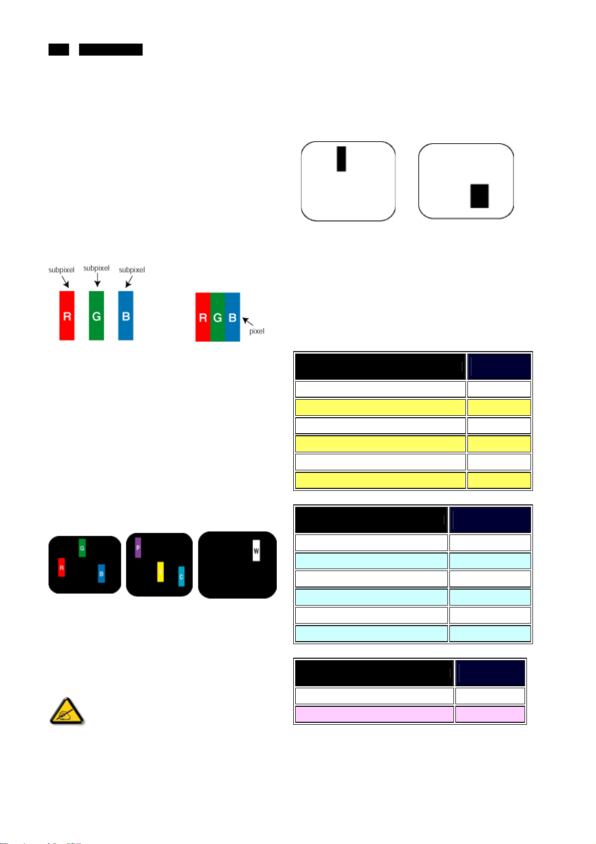
Pixels and Sub pixels
A pixel, or picture element, is composed of thr ee sub pixels in the
primary c olors of red, green and blue. Many pixels together f orm
an image. When all sub pixels of a pixel are lit, the three c olored
sub pixels together appear as a single white pixel. W hen all are
dark, the three colored sub pixels together appear as a single
black pixel. Other combinations of lit and dark sub pixels appear
as single pixels of other colors.
Black Dot D ef ects B lack dot defects ap pear as p ixels or sub
pixels that are always dark or 'off'. That is, a dark dot is a
sub-pixel that stands out on the screen when the monitor
displays a light pattern. These are the types of black dot defects:
ʳ
One dark sub pixel
Proximity of Pixel Defects
Becaus e pixel and sub pixels defects of the same type that are
near to one another may be mor e noticeable, Philips also
specifies tolerances for the proximity of pixel defects.
Pixel D efect Toleranc es
In order to qualify for repair or replacement due to pixel defects
during the warr anty period, a TFT LCD panel in a Philips flat
panel monitor must have pixel or sub pixel defects exceeding the
tolerances listed in the following tables.
BRIGHT DOT DEFECTS
MODEL
1 lit subpixel 3
2 adjacent lit s ubpixels 1
ʳ
Two or three adjacent dark sub
pixels
ʳ
ACCEPTABLE
LEVEL
190CW9
Types of Pixel Defects
Pixel and sub pixel defects appear on the screen in different
ways. There are two categories of pixel defects and several types
of sub pixel defects within each category.
Bright Dot Defects Bright dot defects appear as pixels or sub
pixels that are always lit or 'on'. That is, a bright dot is a sub-pixel
that stands out on the screen when the monitor dis plays a dark
pattern. There are the types of br ight dot defects:
ʳ
Two adjacent lit
http://www.wjel.net
sub pixels:
One lit red, green or
blue sub pixel
ʳ
A red or blue bright dot must be more than 50
percent brighter than neighboring dots while a
green bright dot is 30 percent brighter than
ʳ
neighboring dots.
-Red+Blue=
Purple
- Red + G reen =
Yellow
- Green + B lue =
Cyan (Light Blue)
ʳ
Three adjacent lit sub
pixels (one white
pixel)
ʳ
3 adjacent lit s ubpixels (one white pixel) 0
Distance between two bright dot defects* >15mm
Total bright dot defects of all types 3
BLACK DOT DEFECTS
MODEL
1 dark subpixel 5
2 adjacent dark subpixels 2
ʳ
3 adjacent dark subpixels 0
Dis tanc e between two black dot defects* >15mm
Tot al black dot defects of all types 5
TOTAL DOT DEFECTS
MODEL
Total bright or black dot defects of all types 5
Note:
* 1 or 2 adjacent sub pixel defects = 1 dot defect
ACCEPTABLE
LEVEL
190CW9
ACCEPTABLE
LEVEL
190CW9

Mechanical Instructions
190CW9 LCD 11
Disassemble the Signal cable
2 screws Bring the signal cable
Disassemble the stand
Disassemble the stand
1 holder Of the column
6 screws Bring the stand
Disassemble it
With driver like
Ϙԫϙ
1.turn over the monitor ,
2.take up the RC from the bottom size.
3. Tear off this one acetic tape of C/B FFC
4.Tear down the FFC of the C/B and LED Board in
I/F
5.Take off the Rear cover from the monitor
LED/B FFC
C/B
Disassembly the screw*1 of the RC
http://www.wjel.net
disassembly the bezel from the monitor, notice
the disassembly orde
1.Top (1) parts of bezel
2.Left (2) parts of bezel
3. UP-Right (3) parts of bezel
1
2
3
1.Take off the Tape AL with the SHD and the
Mylar-AL.
2.Tear off the top and the bottom size tape below of
the Mylar-AL
Pull out these lamp wires.
4 lamp Wires Take off the Tape AL*1
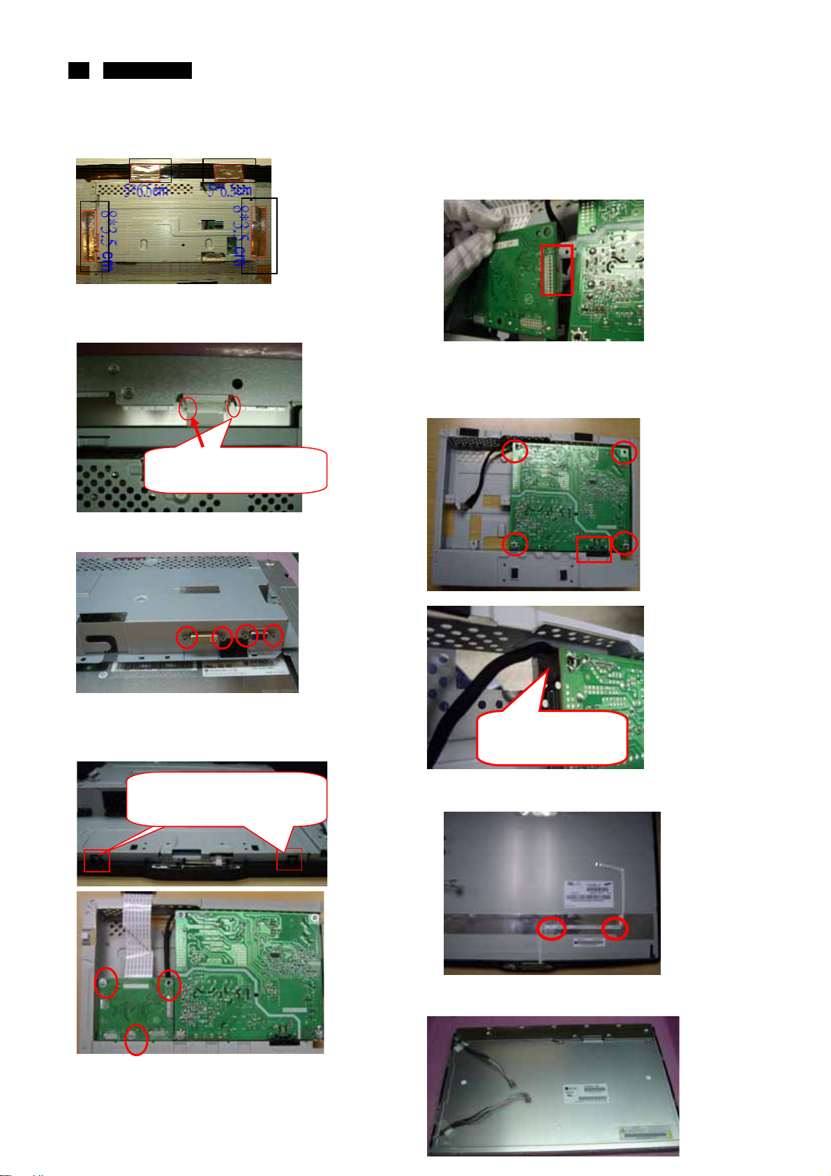
12 190CW9 LCD
Mechanical Instructions
Take off the Tape AL*4
Unlock the LVDS-FFC by using two hands(see
note).
The locking-latch of
LVDS cable’s housing
Uplift the I/F. Pull out the cable of Power board in I/F
Board. Take the I/F Board from Main-BKT and then
put it on the cushion
Disassemble the AC-Socket from the P/B and The
main-BKT. Disassemble the I/F board
4 screws Take the Power Board from Main-BKT
and then put it on the cushion
Disassemble the hexangular screws*4
Turn over the Main-BKT.
Disassemble the I/F board
3screws
Take up the SHD come from this
two rib of the BZL.
http://www.wjel.net
Let the wire walk
out from the rib
Take off the tape below of the LED/B FFC.
Take off the BZL of from the panel .
Take off the mylar-AL from the panel.
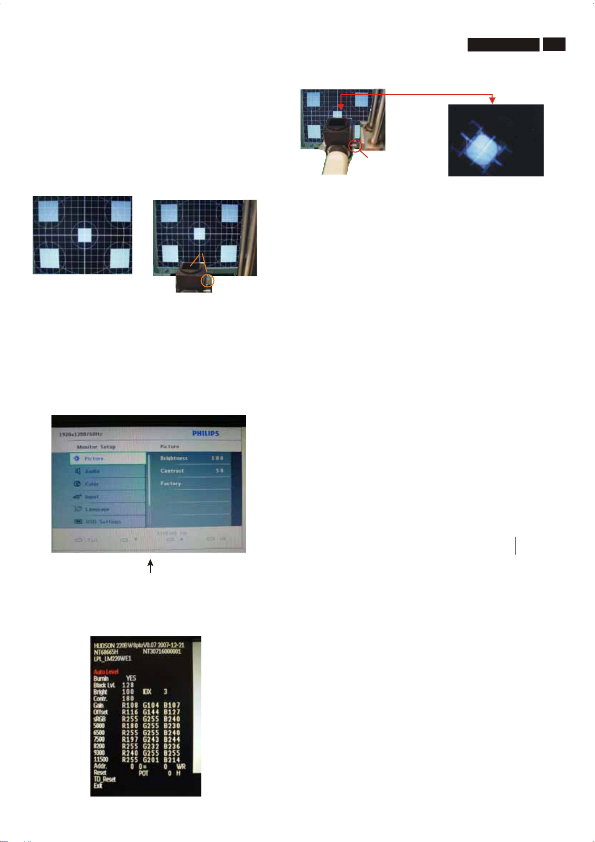
Color Adjustment
Alignment procedure
1. T urn on the LCD monitor .
2.T urn on the T iming/pattern generator . See Fig.1
3. Preset LCD color Analyzer CA-1 10
-Remove the lens protective cover of probe CA-A30.
-Set measuring/viewing selector to measuring position for reset
analyzer .(zero calibration) as Fig.2
- T urn on the color analyzer (CA-1 10)
-Press 0-CAL button to starting reset analyzer .
190CW9 LCD
Measurement/viewing selector
Fig.5
5.Display
Press "UP" or "DOWN" button to select . Change the value
by "UP" or "DOWN" key until the X, Y co-ordinates as below
13
Clear image
Fig. 2
Fig. 1
Fig. 2
4. Access Factory Mode
1). Turn off monitor.
2).
[Push "AUT O" & "MENU" buttons at the same time and hold them]
+[Press "power" button untill comes out "Windows screen" ]
=> then release all buttons
3).Press "MENU button, wait until the OSD menu with
Characters" " (below OSD
menu) come on the Screen of the monitor. as shown in Fig3.
4). Press button, then select factory mode indicator by"MENU" "LEFT"
or "RIGHT" button .Press"MENU" button to bring up submenu
windows as below:
"
HUDSON 240BW8 V0.13 2007-08-10
Factory Mode indicator
Fig. 3
http://www.wjel.net
5.1 White colo r adjustmen
Ther e are t hree f actory pres et w hite c olor 9300K , 6500K , s R G B.
Apply full w hite pattern, with brightnes s in 100 % pos ition
and the c ontras t c ontrol at 50 % pos ition.
The 1931 C IE C hromatic ity (c olor triangle) diagr am (x ,y )
c oordinate for the s c reen c enter s hould be:
Production Product SPEC
5000K x = 0.345 ± 0.006 5000K x = 0.345 ± 0.02
6500K x = 0.313 ± 0.006 6500K x = 0.313 ± 0.02
7500K x = 0.298 ± 0.006 7500K x = 0.298 ± 0.02
8200K x = 0.291 ± 0.006 8200K x = 0.291 ± 0.02
9300K x = 0.283 ± 0.006 9300K x = 0.283 ± 0.02
11500K x = 0.270 ± 0.006 11500K x = 0.270 ± 0.02
Quality inspect
5000K x = 0.345 ± 0.015
6500K x = 0.313 ± 0.015
7500K x = 0.298 ± 0.015
8200K x = 0.291 ± 0.015
9300K x = 0.283 ± 0.015
11500K x = 0.270 ± 0.015
t
y = 0.357 ± 0.006 y = 0.357 ± 0.02
y = 0.329 ± 0.006 y = 0.329 ± 0.02
y = 0.314 ± 0.006 y = 0.314 ± 0.02
y = 0.306 ± 0.006 y = 0.306 ± 0.02
y = 0.297 ± 0.006 y = 0.297 ± 0.02
y = 0.281 ± 0.006 y = 0.281 ± 0.02
y = 0.357 ± 0.015
y = 0.329 ± 0.015
y = 0.314 ± 0.015
y = 0.306 ± 0.015
y = 0.297 ± 0.015
y = 0.281 ± 0.015
Fig. 4

14 190CW9 LCD
FAQs (Frequently Asked Questionis)
General FAQs
Q: When I install my monitor what should I do if the screen
shows 'Cannot display this video mode'?
A: Recommended video mode for Philips 19": 1440x900
@60Hz.
1.Unplug all cables, then connect your PC to the monitor that you
used previously.
2.In the Windows Start Menu, select Settings/Control Panel. In
the Control Panel W indow, select the Display icon. Inside the
Display Control Panel, select the 'Settings' tab. Under the setting
tab, in box labeled 'desktop area', move the slidebar to 1440x900
pixels (19").
3.Open 'Advanced Properties' and s et the Refresh Rate to 60Hz,
then click OK.
4.Restart your c omputer and repeat step 2 and 3 to verify that
your PC is set at 1440x900@60Hz (19").
5.Shut down your c omputer, disconnect your old monitor and
reconnect your Philips LCD monitor.
6.Turn on your monitor and then turn on your PC.
Q: What are the .inf and .icm files on the CD-ROM? How do I
install the driv ers (.inf and .icm)?
A: These are the driver files f or your monitor. Follow the
instructions in your user manual to install the drivers. Your
computer may ask you for monitor drivers (.inf and .icm files) or a
driver disk when you first install your monitor. Follow the
instructions to insert the ( companion CD-ROM) included in this
package. Monitor drivers (.inf and .icm files) will be installed
automatically.
Q: How do I adjust the resolution?
A: Your video card/graphic driver and monitor together determine
the available resolutions. You can select the desired resolution
under W indows® Control Panel with the "Display pr operties".
Q: What if I get lost when I am making monitor adjustments?
Q: Will the LCD screen be resistant to scratches?
A: A protective coating is applied to the surface of the LCD, which
is durable to a certain extent (approximately up to the hardness
of a 2H pencil). In general, it is r ecommended that the panel
surface is not subject to any excessive shocks or scratches.
Q: How should I clean the LC D surface?
A: For normal cleaning, us e a clean, soft cloth. For extens ive
cleaning, pleas e use isopropyl alc ohol. Do not use other solvents
such as ethyl alcohol, ethanol, acetone, hexane, etc.
Q:Can I change the color setting of my monitor?
A:Yes, you can change your color setting through OSD control as
the following procedures,
1. Press "Menu" to show the OSD (On Screen Display) menu
2. Press "Down Arrow" to select the option "Color" then press
"OK" to enter c olor setting, there are three s ettings as below.
a. Color Temperature; The six settings are 5000K, 6500K,
7500K, 8200K, 9300K and 11500K. W ith settings in the 5000K
range the panel appears ‘warm,' with a red-white color tone,
while a 11500K temperature yields ‘c ool, blue-white toning."
b. sRGB; this is a standard setting for ensuring correct exchange
of colors between different device (e.g. digital cameras, monitors,
printers, scanners, etc)
c. User Define; the user can choose his/her preferenc e color
setting by adjusting red, green blue color.
d. Gamma; The five settings are 1.8, 2.0, 2.2, 2.4, and 2.6.
*A measurement of the color of light radiated by an object while it
is being heated. This measurement is expressed in terms of
absolute scale, (degrees Kelvin). Lower Kevin temperatures such
as 2004K are red; higher temperatures such as 9300K are blue.
Neutral temperature is white, at 6504K.
Screen Adjustments
Q: When I install my monitor, how do I get the best
performance from the monitor?
A: Simply press the Menu button, the Setup button, then select
'Reset' t o recall all of the origin al f actor y settings
Q: What is the Auto function?
A: The AUTO adjustment key restores the optimal screen
position, phas e and clock settings by pressing of a single
button – without the need to navigate through OSD (On Screen
Display) menus and control keys.
Note: Auto function is available in selected models only.
Q: My Monitor has no power (Power LED does not light up).
What should I do?
http://www.wjel.net
A: Make sure the AC power cord is connected between the
monitor and AC outlet, and click a key on keyboard/mouse to
wake up the PC.
Q: Will the LCD monitor accept an interlaced signal under
PC models?
A: No. If an Interlace signal is us ed, the screen displays both odd
and even horizontal scanning lines at the same time, thus
distorting the picture.
Q: What does the Refresh Rate mean for LCD?
A: Unlike CRT display technology, in which the speed of the
electron beam is swept from the top to the bottom of the scr een
determines flicker, an active matrix display uses an active
element (TFT) to control each individual pixel and the refresh
rate is therefore not really applicable to LCD technology.
A:For best perf ormance, make sur e your dis play s ettings are s et
at 1440x900@60Hz f or 19".
Q: How do LCDs compare to CRTs in terms of radiation?
A: Because LCDs do not use an electron gun, they do not
generate the same amount of radiation at the screen surface.
Compatibility with other Peripherals
Q: Can I connect my LCD monitor to any PC, workstation or
Mac?
A: Yes. All Philips LCD monitors are fully compatible with
standard PCs, Macs and workstations. You may need a cable
adapter to connect the monitor to your Mac system. Please
contact your Philips sales representative f or more information.
Q: Are Philips LCD monitors Plug-and-Play?
A: Yes, the monitors are Plug-and-Play compatible with
Windows® 95, 98, 2000, XP and Vista.
Q: What is USB ( Universal Serial Bus)?
A: Think of USB as a smart plug for PC peripherals. USB
automatically determines resources (like driver software and bus
bandwidth) required by peripherals. USB makes necessary
resources available without user intervention. There are three
main benefits of USB. USB eliminates "case anxiety," the fear of
removing the computer case to install circuit board cards -- that
often requires adjustment of c omplicated IRQ settings -- f or
add-on peripherals. USB does away with "port gridlock." W ithout
USB, PCs are normally limited to one printer, two Com port

FAQs (Frequently Asked Questionis)
devices (usually a mouse and modem), one Enhanced Parallel
Port add-on (scanner or video camera, f or example), and a
joystick. More and more peripherals for multimedia computers
come on the market every day. With USB, up to 127 devic es c an
run simultaneous ly on one computer. USB permits "hot plug-in."
No need to shut down, plug in, reboot and run set up to install
peripherals. No need to go through the reverse process to unplug
a device. Bottom line: USB tr ansf orms today's "Plug- and-Pr ay"
into true Plug-and-Play!
Please refer to gloss ary for more information about USB
Q:WhatisaUSBhub?
A: A USB hub provides additional connections to the Universal
Serial Bus. A hub's upstream port connects a hub to the host,
usually a PC. Multiple downstream ports in a hub allows
connection to another hub or device, such as a USB keyboard,
camera or printer
LCD Panel Technology
Q: What is a Liquid Crystal Display?
A: A Liquid Crystal Display (LCD) is an optical device that is
commonly used to display ASCII characters and images on
digital items such as watches, c alculators, portable game
consoles, etc. LCD is the technology used for displays in
notebooks and other small computers. Like light-emitting diode
and gas-plasma technologies, LCD allows displays to be much
thinner than cathode ray tube (CRT) technology. LCD consumes
much less power than LED and gas-displays because it works on
the principle of blocking light rather than emitting it.
Q:WhatdifferentiatespassivematrixLCDsfromactive
matrix LCDs?
190CW9 LCD 15
Q: What kind of wide-angle technology is available? How
does it work?
A: The TFT LCD panel is an element that controls/displays the
inlet of a backlight using the dual-refraction of a liquid crystal.
Using the property that the projection of inlet light refracts toward
the major axis of the liquid element, it c ontrols the dir ection of
inlet light and displays it. Since the refraction ratio of inlet light on
liquid crystal varies with the inlet angle of the light, the viewing
angle of a TFT is muc h narrower than that of a CDT. Usually, the
viewing angle refers t o the point where the contrast ration is 10.
Many ways to widen the viewing angle are currently being
developed and the most common approach is to use a wide
viewing angle film, which widens the viewing angle by varying the
refraction ratio. IPS (In Plane Switching) or MVA (Multi Vertic al
Aligned) is also us ed to give a wider viewing angle.
Q: Why is there no flicker on an LCD Monitor?
A: Technically speaking, LCDs do flicker, but the cause of the
phenomenon is diff erent from that of a CRT monitor -- and it has
no impact of the ease of viewing. Flickering in an LCD monitor
relates to usually undetectable luminance caused by the
difference between positive and negative voltage. On the other
hand, CRT flicker ing that can irritate the human eye occurs when
the on/off action of the fluoresc ent object becomes vis ible. Since
the reaction speed of liquid crystal in an LCD panel is much
slower, this troublesome f orm of flickering is not present in an
LCD display.
Q: Why is an LCD monitor virtually low of Electro Magnetic
Interference?
A: Unlike a CRT, an LCD monitor does not have key parts that
generate Electro Magnetic Interference, especially magnetic
fields. Also, since an LCD display utilizes relatively low power, its
power supply is extremely quiet.
A: An LCD is made with either a passive matrix or an active
matrix display grid. An active matrix has a transistor located at
each pixel intersection, requiring less current to contr ol the
luminance of a pixel. For this reason, the current in an active
matrix display can be switched on and off more frequently,
improving the screen refr esh time (your mouse pointer will
appear to move more smoothly across the screen, for example).
The passive matrix LCD has a grid of conductors with pixels
located at each intersection in the grid.
Q: What are the advantages of TFT LCD compared with
CRT?
A: In a CRT monitor, a gun s hoots electrons and general light by
colliding polarized electrons on fluorescent glass. Therefore,
CRT monitors basically operate with an analog RGB signal. A
TFT LCD monitor is a device that displays an input image by
operating a liquid crystal panel. The TFT has a fundamentally
different structure than a CRT: Each cell has an active matrix
structure and independent active elements. A TFT LCD has two
glass panels and the space between them is filled with liquid
crystal. W hen each cell is connected with electrodes and
impressed with voltage, the molecular str ucture of the liquid
crystal is altered and controls the amount of inlet lighting to
display images. A TFT LCD has s everal advantages over a CRT,
since it can be very thin and no flickering occurs becaus e it does
not use the scanning method.
Q: Why is vertical fr equency of 60Hz optimal for an LCD
monitor?
A: Unlike a CDT monitor, the TFT LCD panel has a fixed
resolution. For example, an XGA monitor has 1024x3 (R, G, B) x
768 pixels and a higher resolution may not be available without
additional softwar e processing. The panel is designed to optimize
the display for a 65MHz dot clock, one of the standards f or XGA
displays. Sinc e the vertical/horizontal frequency for this dot clock
is 60Hz/48kHz, the optimum frequency for this monitor is 60Hz.
http://www.wjel.net
Ergonomics, Ecology and Safety
Standards
Q: What is the CE mark?
A: The CE (Conformité Européenne) mark is required to be
displayed on all regulated products offered for s ale on the
European market. This 'CE' mark means that a product complies
with the relevant European Directive. A European Directive is a
European 'Law' that relates to health, safety, environment and
consumer protection, much the same as the U.S. National
Electrical Code and UL Standards.
Q: Does the LCD monitor conform to general safety
standards?
A: Yes. Philips LCD monitors conf orm to the guidelines of MPR-II
and TCO 99/03 standards for the control of radiation,
electromagnetic waves, energy reduction, electrical safety in the
work envir onment and recyclability. The specification page
provi des d etail ed dat a on safety stand ards.
Q: After I change new PC, I found this information on screen,
how can I do?
A: Because you activate Theft Deterrence function in
SmartControl II. Please c ontact IT manager or Philips Service
Center.
16 190CW9 LCD
Electrical Instructions
1.Electrical characteristics
1.1 Interface signals
1). D-Sub Analog
Input signal: Video, Hsync., Vsync
Video: 0.7 Vp-p, input impedance, 75 ohm @DC
Sync.: Separate sync TTL level , input impedance 2.2k ohm terminate
Hsync Positive/Negative
Vsync Positive/Negative
Composite sync TTL level, input impedance 2.2k ohm terminate (Positive/Negative)
Sync on green video 0.3 Vp-p Negative (Video 0.7 Vp-p Positive)
2). DVI-D Digital
Input signal: Single TMDS link (Three channels: RX0-/+, RX1-/+, RX2-/+)
3). USB PLUG support
Input signal: Upstream input (VBUS, D+, D-, GND) via USB-B receptacle.
Output signal: Downstream output (VBUS, D+, D-, GND) through USB-A receptacle
1.2 Interface
1.2.1 D-Sub Cable
Length : 1.8 M +/- 50 mm
Fix with monitor when packing, with transplant pin protective cover.
Connector type : D-Sub male with DDC2B pin assignments.
Blue connector thumb-operated jack screws
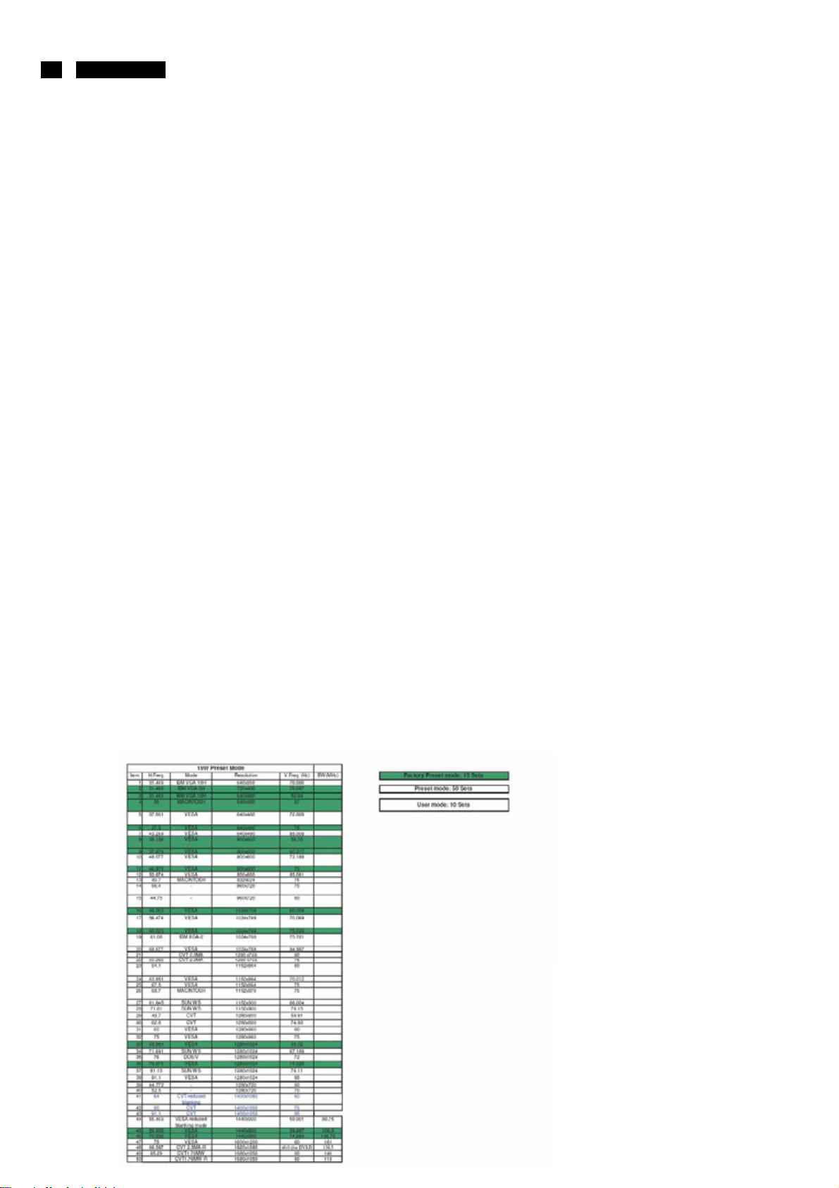
1.3 Timing requirement
1.3.1 Mode storing capacity
Factory preset modes : 13
Preset modes : 50
User modes : 10
Note:1.Screen displays perfect picture at 13 factory-preset modes.
2.Screen displays visible picture with OSD warning when input modes are the 48 preset modes
1.3.2Factory preset modes
http://www.wjel.net

Electrical Instructions
2. White color adjustment
There are three factory preset white color 9300K, 6500K, sRGB. Apply full white pattern, with
brightness in 100 % position and the contrast control at 50 % position. The 1931 CIE
Chromaticity (color triangle) diagram (x,y) coordinate for the screen center should be:
Production Product SPEC
5000K x = 0.345 ± 0.006 5000K x = 0.345 ± 0.02
y = 0.357 ± 0.006 y = 0.357 ± 0.02
6500K x = 0.313 ± 0.006 6500K x = 0.313 ± 0.02
y = 0.329 ± 0.006 y = 0.329 ± 0.02
7500K x = 0.298 ± 0.006 7500K x = 0.298 ± 0.02
y = 0.314 ± 0.006 y = 0.314 ± 0.02
8200K x = 0.291 ± 0.006 8200K x = 0.291 ± 0.02
y = 0.306 ± 0.006 y = 0.306 ± 0.02
9300K x = 0.283 ± 0.006 9300K x = 0.283 ± 0.02
y = 0.297 ± 0.006 y = 0.297 ± 0.02
11500K x = 0.270 ± 0.006 11500K x = 0.270 ± 0.02
y = 0.281 ± 0.006 y = 0.281 ± 0.02
190CW9 LCD
17
Quality inspect
5000K x = 0.345 ± 0.015
y = 0.357 ± 0.015
6500K x = 0.313 ± 0.015
y = 0.329 ± 0.015
7500K x = 0.298 ± 0.015
y = 0.314 ± 0.015
8200K x = 0.291 ± 0.015
y = 0.306 ± 0.015
9300K x = 0.283 ± 0.015
y = 0.297 ± 0.015
11500K x = 0.270 ± 0.015
http://www.wjel.net
y = 0.281 ± 0.015
18
p
190CW9 LCD
DDC Data Re-programming
In case the DDC data memory IC or main EEPROM which storage all factory settings
were replaced due to a defect, the serial numbers have to be re-programmed "Analog
DDC IC, Digital DDC IC & EEPROM".
It is advised to re-soldered DDC IC and main EEPROM from the old board onto the new
board if circuit board have been replaced, in this case the DDC data does not need to be
re-programmed.
Additional information
Additional information about DDC (Display Data Channel) may be obtained from Video
Electronics Standards Association (VESA).
Extended Display Identification Data(EDID) information may be also obtained from
VESA.
Configuration and procedure
"PI-EDID" The software is provided by IMS to upgrade the firmware of CPU.
PI-EDID Tools is for the interface between "Parallel Port of PC" and "15 pin-D-SUB
connector of Monitor".
It is a windows-based program, which cannot be run in MS-DOS.
System and equipment requirements
1. An Pentium (or above) personal computer or compatible.
2. Microsoft operation system Windows 95/98/2000/XP and Port95NT.exe.
3. EDID Software "PI-EDID.exe"
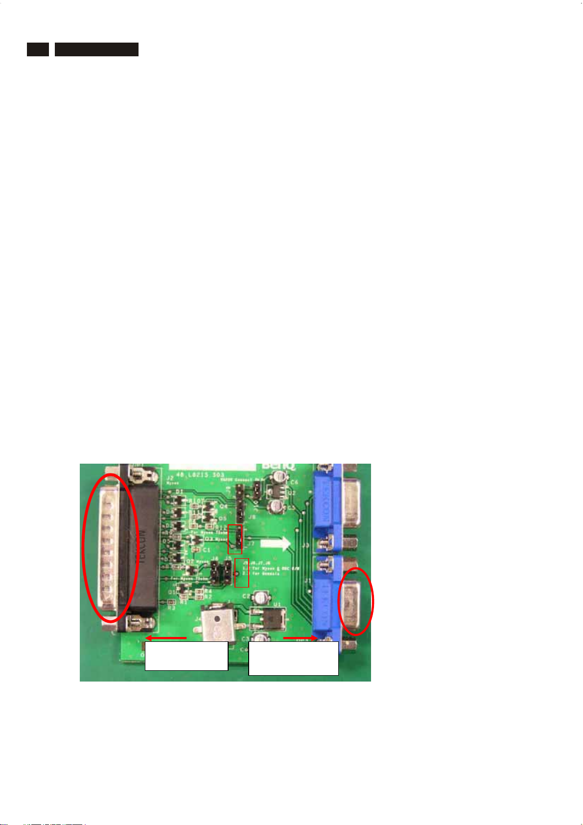
4. ISP boardas shown in Fig. 1
DDC Instructions
And I2C Board Jump wire should follow
3
2
1
2
http://www.wjel.net
Connected to
rint cord and
Connected to
Display Signal
J10 (short) , J9 (open), J5/J6/ (1and 2 pin short)
J7/J8 (1 and 2 pin short)
Fig.1
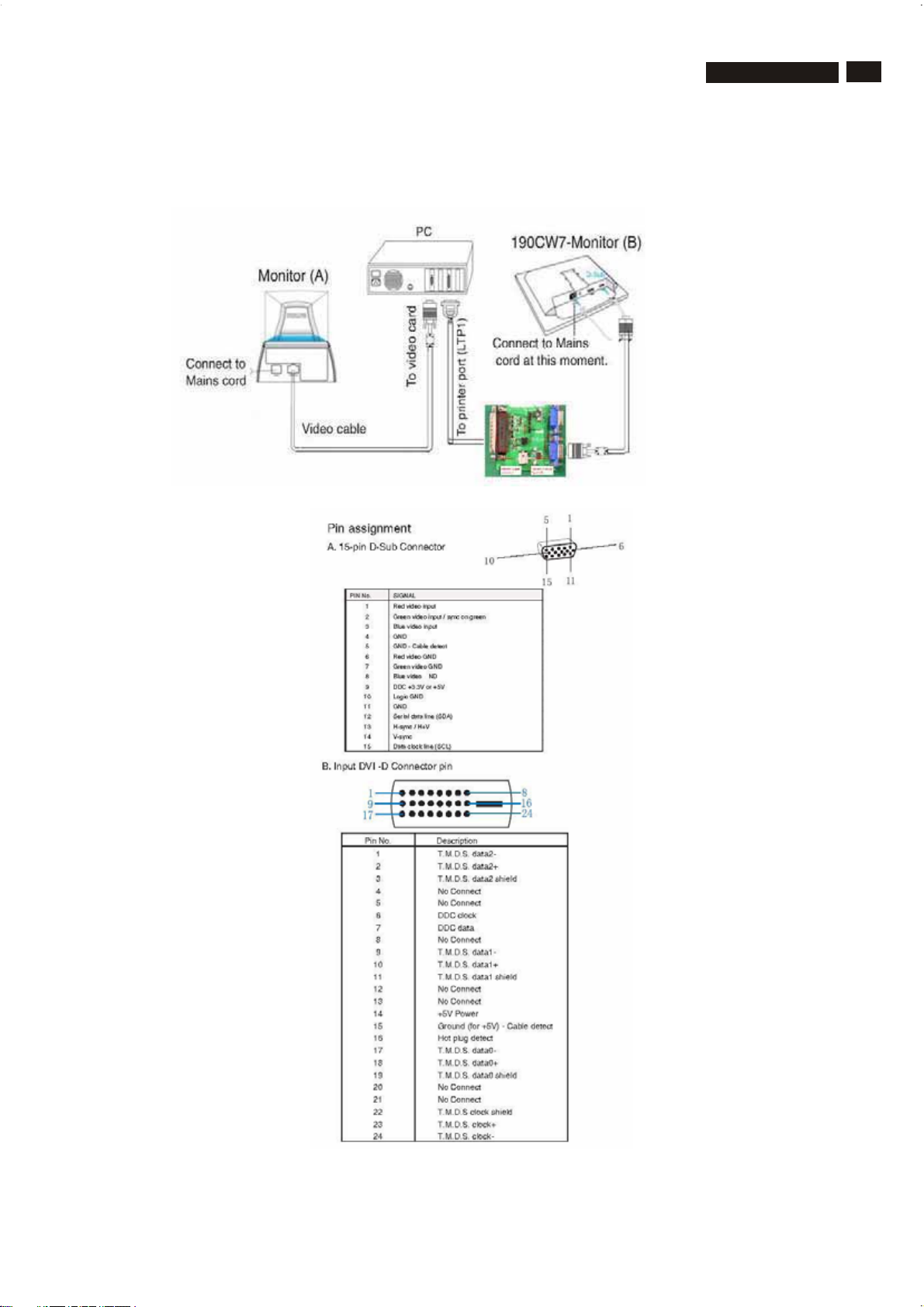
DDC Instructions
5. Connect and Mains cord to Monitor as shown in Fig.2.
Fig.2
190CW9 LCD
19
http://www.wjel.net
Fig. 2a
20
190CW9 LCD
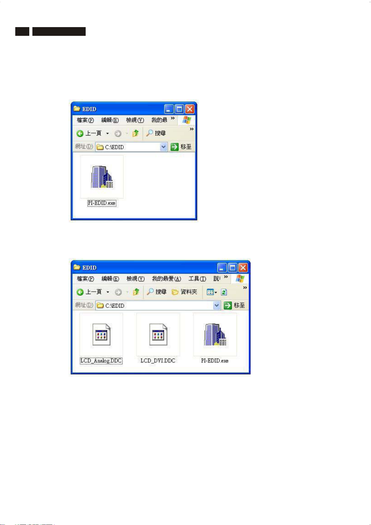
6. Setup the Philips-IMS EDID Tools program
Step 1: Make a folder in your PC as shown in Fig. 3.
For example: C:\EDID
Step 2: Copy PI-EDID Software into your folder as shown in Fig.3.
DDC Instructions
Step 3: Copy the
LCD_Analog.ddc and LCD_DVI.ddc
to C:\EDID as shown in Fig. 4 .
http://www.wjel.net
Fig.3
Fig.4
DDC Instructions
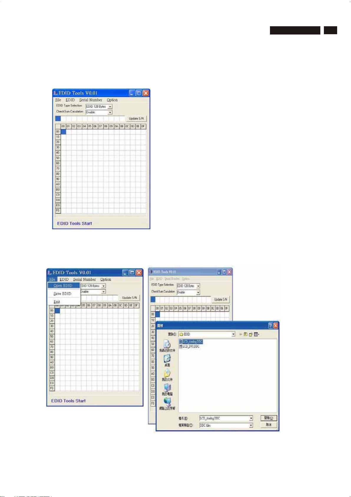
Update the DDC
1. Connect DSUB Cable to I2C Board.
Double click the PI-EDID.exe icon in desktop then appears window as shown in Fig.5.
190CW9 LCD
21
Fig.5
2. Press File->OPEN EDID to Load DDC file as shown in Fig.6.
Load Analog EDID file LCD_Analog.ddc to PI-EDID.exe
http://www.wjel.net
Fig.6
22
190CW9 LCD
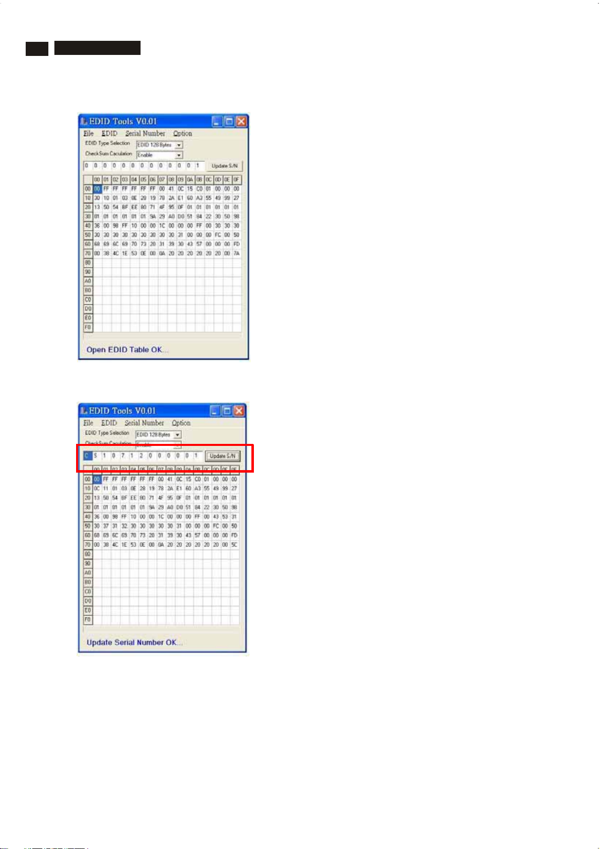
3. Load EDID file OK as shown in Fig.7.
DDC Instructions
Fig.7
4. Modify Serial Number then Press “ Update S/N” button asshown in Fig.8.
http://www.wjel.net
Fig.8
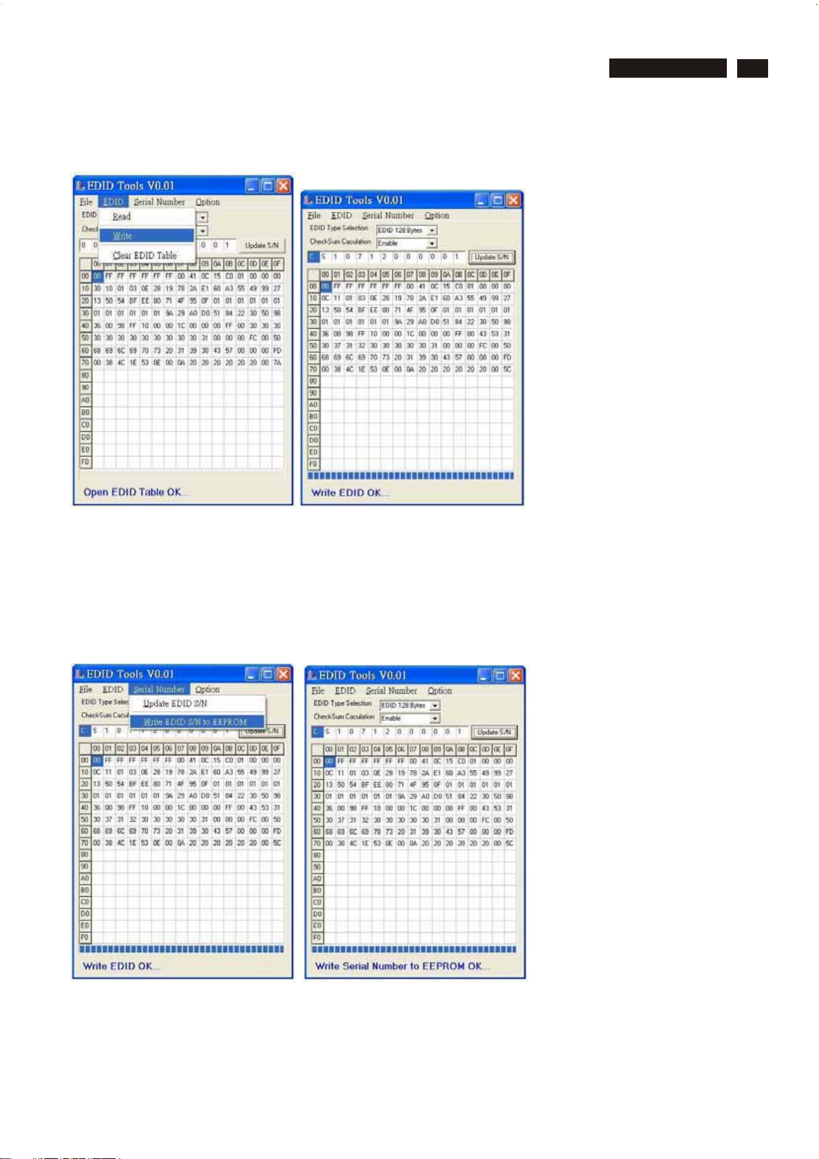
DDC Instructions
5. Press EDID->Write to write EDID data to EEPROM as shown in Fig. 9.
190CW9 LCD
23
Fig.9
6. Connect DVI Cable to I2C Board.
Repeat Step 1~5 to write DVI EDID file.
7. Enter Factory Mode then Press the Serial Number->Write EDIDS/N to EEPROM as
shown in Fig.10
Note: If not enter Factory Mode, this Wrote EDID S/N will not work.
http://www.wjel.net
Fig.10
24
190CW9 LCD
DDC instruction
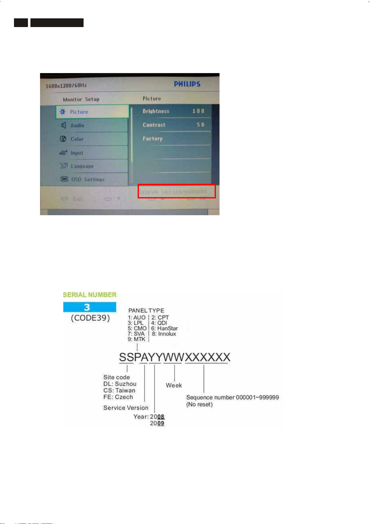
8. Press Monitor Menu Key to check OSD Serial number is the same as PI-EDID write
data as shown in Fig.10
Note: If not the same, please rewrite EDID S/N again.
9 Turn off the monitor, exit the factory mode.
Serial Number Definition
http://www.wjel.net
Fig.14

//////////Displaying Monitor EDID//////////
128 bytes EDID Data (Hex):
0123456789
0: 00 FF FF FF FF FF FF 00 41 0C
10:23C075200B0019120103
20:0E281978EEDE95A3544C
30:99260F5054BFEF809500
40:714F81808140950F0101
50:010101019A29A0D05184
60:22305098360098FF1000
70:001C000000FF00444C34
80:30383235373239323035
90:000000FC005068696C69
100: 70 73 20 31 39 30 43 57 00 00
110: 00 FD 00 38 4C 1E 53 0E 00 0A
120: 20 20 20 20 20 20 00 42
Decoded EDID data
<---Header--->
Header: 00FFFFFFFFFFFF00
<-x-Head er-x->
<---Vendor/Product Identification--->
ID Manuf acturer Name: PHL
ID Product Code: 49187
ID Serial Number: 000B2075
Week of Manufacture: 25
Year of Manuf acture: 2008
<-x-Vendor/Product Identification- x->
<---EDID Structure Version/Revision--->
EDID Version#: 1
EDID Revision#: 3
<-x-EDID Structure Version/Revision-x->
<---Basic Display Parameters/Features--->
Video i/p definition: Analog
Setup: Blank-to-Black not expected
Seperate Syncs. support: Yes
Composite Sync. support: Yes
Vsync. Pulse: serration r equired
Max Horz Image Size: 40 cm.
Max Vert Image Size: 25 cm.
Display Gamma: 2.2
Display Type: RGB color display
Standard Default Color Space: Yes
Features, Preferred Timing Mode: In first detailed block
Features, GTF support: No
DPMS Features, Stand-by: Yes
DPMS Features, Suspend: Yes
DPMS Features, Active Off: Yes
<-x-B asic Display Parameters/Features-x->
<---Color Characteristics--->
Red x: 0.639648
Red y: 0.329102
Green x: 0.299805
Green y: 0.599609
Blue x: 0.150391
Blue y: 5.95703e-002
White x: 0.313477
White y: 0.329102
<-x-Color Characteristics-x->
http://www.wjel.net
190CW9 LCD 25
DDC DATA
<---Established Timings--->
Established Timimgs 1: BF
- 720x400 @70Hz
- 640x480 @60Hz
- 640x480 @67Hz
- 640x480 @72Hz
- 640x480 @75Hz
- 800x600 @56Hz
- 800x600 @60Hz
Established Timimgs 2: EF
- 800x600 @72Hz
- 800x600 @75Hz
- 832x624 @75Hz
- 1024x768 @60Hz
- 1024x768 @70Hz
- 1024x768 @75Hz
- 1280x1024 @75Hz
- 1152x870x75Hz
Established Timings 3: 80
<-x-Established Timings-x->
<---Standard Timing Identification--->
Standard Timing: 1440x1440 @60Hz
Standard Timing: 1152x864 @75Hz
Standard Timing: 1280x1024 @60Hz
Standard Timing: 1280x960 @ 60Hz
Standard Timing: 1440x1440 @75Hz
<-x-Standard Timing Identification-x->
<---Detailed Timing Descriptions--->
Detailed Timing: 1440x900 @59Hz
Detailed Timing: FF (Monitor SN) 'DL40825729205'
Detailed Timing: FC (Monitor name) 'Philips 190CW'
Detailed Timing: FD (Monitor limits)
Vert: 56 - 76 H z
Horz: 30 - 83 KHz
Clk: 140 MHz
<-x-Detailed Timing Descriptions-x->
Extension Flag: 00
Checksum: 42

26 190CW9 LCD
//////////Displaying Monitor EDID//////////
DDC DATA
128 bytes EDID Data (Hex):
0123456789
0: 00 FF FF FF FF FF FF 00 41 0C
10:24C0010000000B120103
20:802F1D78EEB505A5564A
30:9A25125054BFEF80B300
40:8180818F9500950FA940
50:010101017C2E90A0601A
60:1E4030203600DA281100
70:001A000000FF00435333
80:30373135303030303031
90:000000FC005068696C69
100: 70 73 20 32 32 30 43 57 00 00
110: 00 FD 00 38 4C 1E 53 11 00 0A
120: 20 20 20 20 20 20 00 EA
Decoded EDID data
<---Header--->
Header: 00FFFFFFFFFFFF00
<-x-Header-x->
<---Vendor/Product Identification--->
ID Manuf acturer Name: PHL
ID Product Code: 49188
ID Serial Number: 00000001
Week of Manufacture: 11
Year of Manuf acture: 2008
<-x-Vendor/Product Identification- x->
<---EDID Structure Version/Revision--->
EDID Version#: 1
EDID Revision#: 3
<-x-EDID Structure Version/Revision-x->
<---Basic Display Parameters/Features--->
Video i/p definition: Analog
Setup: Blank-to-Black not expected
Seperate Syncs. support: No
Composite Sync. support: No
Vsync. Pulse: serration not required
Max Horz Image Size: 47 cm.
Max Vert Image Size: 29 cm.
Display Gamma: 2.2
Display Type: RGB color display
Standard Default Color Space: Yes
Features, Preferred Timing Mode: In first detailed block
Features, GTF support: No
DPMS Features, Stand-by: Yes
DPMS Features, Suspend: Yes
DPMS Features, Active Off: Yes
<-x-Basic Display Parameters/Features-x->
<---Established Timings--->
Established Timimgs 1: BF
- 720x400 @70Hz
- 640x480 @60Hz
- 640x480 @67Hz
- 640x480 @72Hz
- 640x480 @75Hz
- 800x600 @56Hz
- 800x600 @60Hz
Established Timimgs 2: EF
- 800x600 @72Hz
- 800x600 @75Hz
- 832x624 @75Hz
- 1024x768 @60Hz
- 1024x768 @70Hz
- 1024x768 @75Hz
- 1280x1024 @75Hz
- 1152x870x75Hz
Established Timings 3: 80
<-x-Established Timings-x->
<---Standard Timing Identification--->
Standard Timing: 1680x1680 @60Hz
Standard Timing: 1280x1024 @60Hz
Standard Timing: 1280x1024 @75Hz
Standard Timing: 1440x1440 @60Hz
Standard Timing: 1440x1440 @75Hz
Standard Timing: 1600x1200 @60Hz
<-x-Standard Timing Identification-x->
<---Detailed Timing Descriptions--->
Detailed Timing: 1680x1050 @59Hz
Detailed Timing: FF (Monitor SN) 'CS30715000001'
Detailed Timing: FC (Monitor name) 'Philips 220CW'
Detailed Timing: FD (Monitor limits)
Vert: 56 - 76 H z
Horz: 30 - 83 KHz
Clk: 170 MHz
<-x-Detailed Timing Descriptions-x->
Extension Flag: 00
Checksum: EA
<---Color Characteristics--->
Red x: 0.646484
Red y: 0.338867
Green x: 0.290039
Green y: 0.602539
Blue x: 0.144531
Blue y: 7.03125e-002
White x: 0.313477
White y: 0.329102
<-x-Color Characteristics-x->
http://www.wjel.net
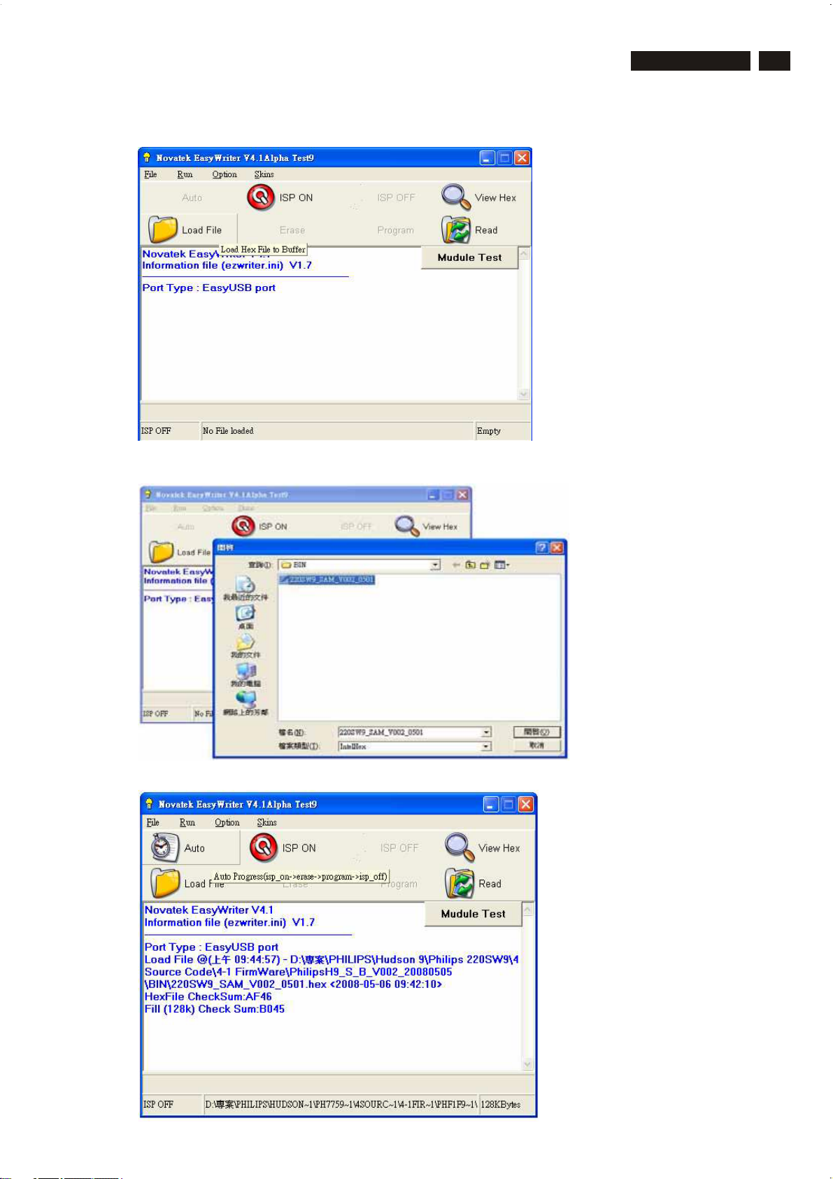
Firmware Upgrade for CPU
Step 1 : Install “P ort95nt.exe”
Restartcomputer.
S tep 2 : D obule c lic k “E a s yU S B W riter\Writer_t9.exe”
Press “Load File”
190CW9 LCD
27
S tep 3 : C hoose *.hex
Step 4 : Press “Auto” to update F/W
http://www.wjel.net
 Loading...