

Philips 190CW7CS/00, 190CW7CS/96, 190CW7CB/69, 190CW7CS/27, 190CW7CS/69 Service Manual
...
Description Page
Important Safety Notice-----------------------------------2
Technical Data----------------------------------------------3
Installation---------------------------------------------------4
Troubleshooting--------------------------------------------5
On Screen Display--------------------------------------6~7
Lock/unlock,Aging,Factory mode-----------------------8
-------------------------------Mechanical Instructions ----------------------------10~11
Color adjustment -----------------------------------------12
Electrical instruction --------------------------------15~16
DDC Instructions&Serial Number ----------------17~23
DDC DATA --------------------------------------------24~25
-----------------------26~27
Philips Pixel Defect Policy 9
FAQs (Frequently Asked Questions)-------------13~14
Firmware Upgrade for CPU-
Horizontal frequencies
30-83kHz
TABLE OF CONTENTS
Published by BCU Monitors Printed in Suzhou Copyright reserved Subject to modification K Jul. 27 2006
Description Page
---------------------------------28
Wiring Diagram------------------------------------------29
Block Diagram--------------------------------------------30
Scaler Diagram&C.B.A. ---------------------------31~37
Power Diagram & C.B.A. --------------------------38~41
Control Diagram&C.B.A. --------------------------42~43
General product specification--------------------44~65
Exploded View -------------------------------------------66
Repair tips--------------------------------------------67~68
Repair Flow chart-----------------------------------69~71
Safety Test Requirments-------------------------------72
Spare/ arts List-----------------73~77
Different Parts List----------------------------------78~85
Revision List----------------------------------------------86
Recommended P
Failure Mode Of Panel-
REFER TO BACK COVER FOR IMPORTANT SAFETY GUIDELINES
CAUTION: USE A SEPARATE ISOLATION TRANSFORMER FOR THIS UNIT WHEN SERVICING.
ANY PERSON ATTEMPTING TO SERVICE THIS CHASSIS MUST FAMILIARIZE HIMSELF WITH THE CHASSIS
AND BE AWARE OF THE NECESSARY SAFETY PRECAUTIONS TO BE USED WHEN SERVICING ELECTRONIC
EQUIPMENT CONTAINING HIGH VOLTAGES.
SAFETY NOTICE
Chassis: HUDSON7
GB
3138 106 10544
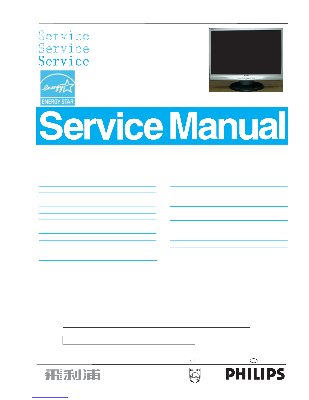
19 inch TFT WXGA LCD Colour Monitor
190CW7CS/00
190CW7CS/27
190CW7CS/69
190CW7CS/75
190CW7CS/93
190CW7CS/96
190CW7CB/69
190CW7CB/93
190WV7CS/00

Important Safety Notice
2
190CW7 LCD
Proper service and repair isimportant to the safe, reliable
operation of all HPConsumer Electronics Company**
Equipment. The service procedures recommended by HP and
described in this service manual are effective methods of
performing service operations. Some ofthese service
operations require the use of tools specially designed for the
purpose. The special tools should be used when and as
recommended.
It is important to note that this manual contains various
CAUTIONS and NOTICES which should be carefully read in
order to minimize the risk of personal injury to service
personnel. The possibility exists that improper service
methods may damage the equipment. It is also important to
understand that these CAUTIONS and NOTICES ARE NOT
EXHAUSTIVE. HP could not possibly know, evaluate and
advise the service trade of all conceivable ways in which
service might be done or of the possible hazardous
consequences of each way. Consequently, HP has not
undertaken any such broad evaluation. Accordingly, a
servicer who uses a service procedure or tool which is not
recommended by HP must first satisfy himself thoroughly that
neither his safety nor the safe operation of the equipment will
be jeopardized by the service method selected.
* * Hereafter throughout this manual, HP Consumer
Electronics Company will bereferred to as HP.
Critical components having special safety characteristics are
identified with a bythe Ref. No. inthe parts list and
enclosed within a broken line*
(where several critical components are grouped in one area)
along with the safety symbol on the schematics or
exploded views.
Use of substitute replacement parts which do not have the
same specified safety characteristics may create shock, fire,
or other hazards.
Under no circumstances should the original design be
modified or altered without written permission from Philips.
Philips assumes no liability, express or implied, arising out of
any unauthorized modification of design.
Servicer assumes all liability.
*BrokenLine
WARNING
Take care during handling the LCD module with backlight
unit
- Must mount the moduleusing mounting holes arranged infour
corners.
- Do not press onthe panel, edge of theframe strongly or electric
shock as this will result in damage to the screen.
- Do not scratch orpress on the panel withany sharp objects, such
as pencil or pen asthis may result in damage to the panel.
- Protect the module fromthe ESD as it maydamage the electronic
circuit (C-MOS).
- Make certain that treatment person s body are grounded through
wrist band.
- Do not leave themodule in high temperature andin areas of high
humidity for a long time.
- Avoid contact with water as it may ashort circuit within the module.
- If the surface ofpanel become dirty, please wipe it off with a soft
material. (Cleaning with a dirty or rough cloth may damage the
panel.)
FOR PRODUCTS CONTAINING LASER :
DANGER- Invisible laser radiation when open.
AVOID DIRECT EXPOSURE TO BEAM.
CAUTION- Use of controls or adjustments or
performance of procedures other than
those specified herein may result in
hazardous radiation exposure.
CAUTION- The use of optical instruments with this
product will increase eye hazard.
TO ENSURE THE CONTINUED RELIABILITY OF THIS
PRODUCT, USE ONLY ORIGINAL MANUFACTURER'S
REPLACEMENT PARTS, WHICH ARE LISTED WITH THEIR PART
NUMBERS IN THE PARTS LIST SECTION OF THIS
SERVICE MANUAL.
3
Technical Data
190CW7 LCD
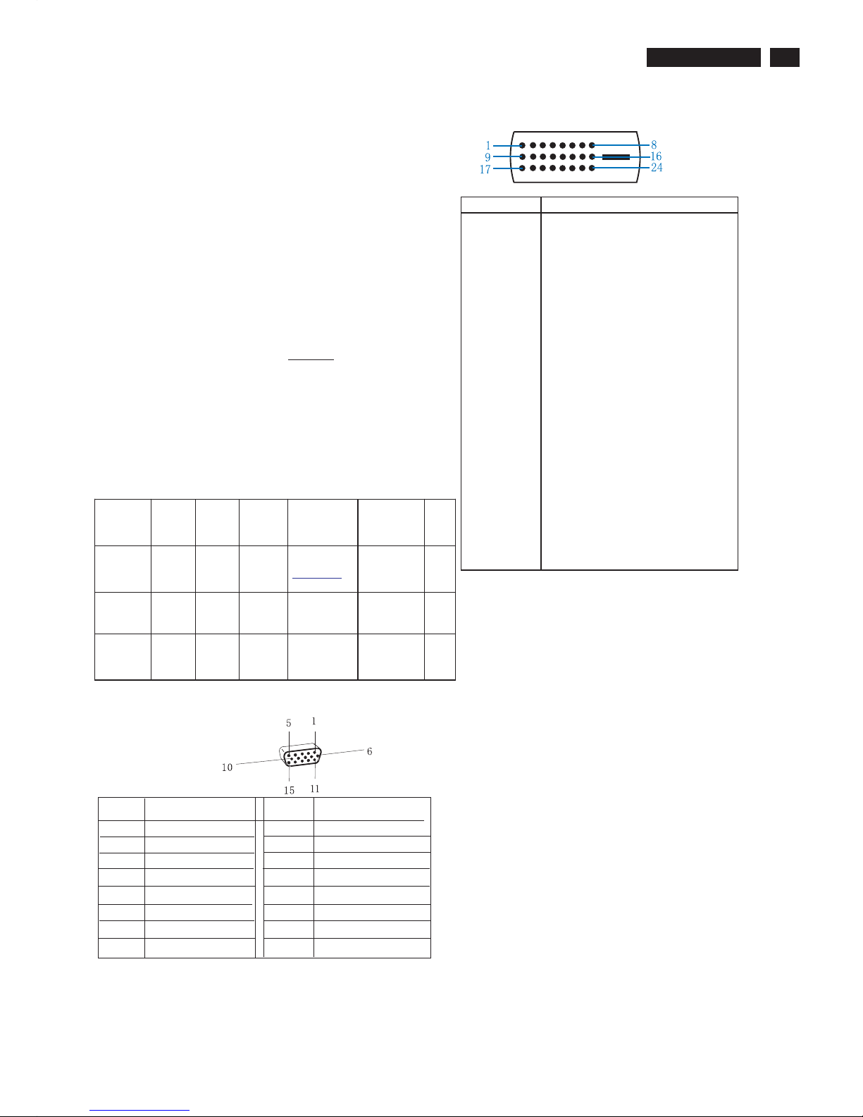
Pin Assignment
Input DVI-D connector pin
Red video input
Green video input
Blue video input
GND
Cable detect
Red video GND
Green video GND
Blue video GND
DDC +3.3V OR +5V
GND
GND
Serial data line (SDA)
H-sync
V-sync
Data clock line (SCL)
7
8
6
5
4
3
2
1
9
10
11
12
13
14
15
Pin No.
Pin No.
Assignment
Assignment
Pin No. Description
1
T.M.D.S. data2-
2
T.M.D.S. data2+
3
T.M.D.S. data2 shield
4
No Connect
5
No Connect
6
DDC clock
7
DDC data
8
No Connect
9
T.M.D.S. data1-
10
T.M.D.S. data1+
11
T.M.D.S. data1 shield
12
No Connect
13
No Connect
14
+5V Power
15
Ground (for +5V) - Cable detect
16
Hot plug detect
17
T.M.D.S. data0-
18
T.M.D.S. data0+
19
T.M.D.S. data0 shield
20
No Connect
21
No Connect
22
T.M.D.S clock shield
23
T.M.D.S. clock+
24
T.M.D.S. clock-
LCD panel
Type NR. : M190A1
Outside dimensions : 427.2(w)*277.4(h)*17.0(d) (Typ) mm
Pitch ( mm ) : 0.285 mm x 0.285 mm
Color pixel arrangement : RGB vertical stripes
Display surface : low reflection, antiglare with hard coating
Color depth : 16.2M colors (6 bits+FRC)
Backlight : CCFL edge light system
Active area(WxH) : 410.4 x 256.5mm (19.05" diagonal)
View angle (CR>10) : 75/75 (min), 85/85 (typ) for Horizontal & 70/
70 (min), 80/80 (typ) for Vertical
Contrast ratio : 850:1(Typ.) 500:1(Min.)
White luminance : Original color 230 nits (Min), 300 nits (Typ.)
Response time : 5ms (typ)
Scanning frequencies
Hor. : 30 - 83 K Hz
Ver. : 55 -75Hz
Video dot rate : <140 MHz
Power input : 90-264 V AC, 50/60 ± 2Hz
Power consumption : < 36W(typ.) maximum
Ambi ent temp eratu re : 0 °C-35°C
Power input connection
Power cord length : 1.8 M
Power cord type : 3 leads power cord with
protective earth plug.
Power m anagement
The monitor must comply with the Microsoft On Now specification, with
two power management states, as defined by the VESA DPMS document.
The monitor must appropriately display the DPMS state.
Mode HSYNC VSYNC Video Pwr-cons . Indi cation Rec.
time
Power-OnOn On active < 36 W(typ..)
34 W (typ.)
Green LED --
Off Off Off blanked < 1 W Amber LED < 3
s
DC
Power Off
N/A < 1 W LED Off
Susceptibility of display to external environment
Operating
- Temperature : 0 to 40 degree C
- Humidity : 80% max
- Altitude : 0-3658m
- Air pressure : 600-1100 mBAR
Storage
- Temperature : -20 to 60 degree C
- Humidity : 95% max
- Altitude : 0-12192m
- Air pressure : 300-1100 mBAR
4
190CW7 LCD
Installation
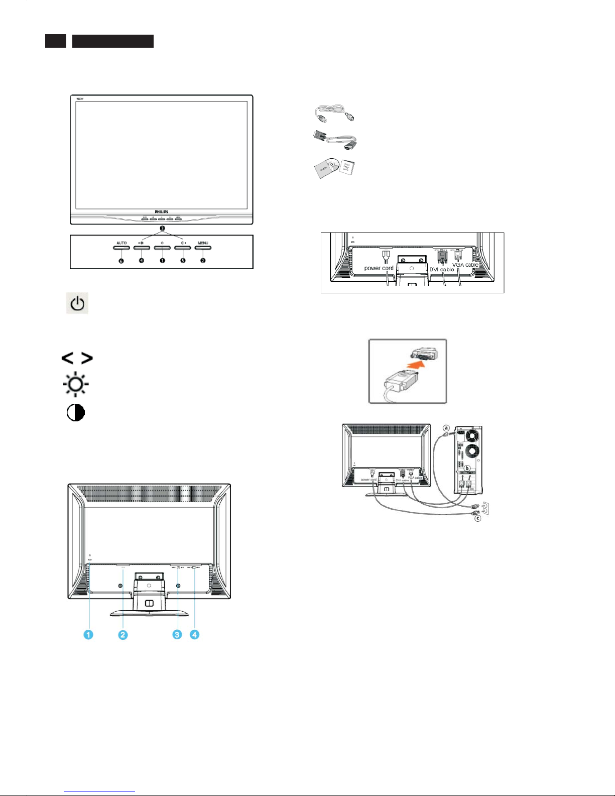
Front View
Rear View
Power cord
VGA signal cable
EDFU pack
Accessory Pack
Item Description
Connecting to Your PC
1
2
3
4
5
6 AUTO
To switch monitor's power On and Off
Automatically adjust the horizontal position,
vertical position, phase and clock setting
To access OSD menu
To move the adjust
To adjust brightness of the display
/ to confirm
To adjust contrast of the display
1) Connect the power cord to the back of the monitor firmly.
Notes:If you use an Apple Macintosh , you need to connect the
special Mac adapter to one end of the monitor signal cable.
TM
1
2
3
4
Kensington anti-thief lock
AC power input
DVI-D input
VGA input
2)
(a)
(b)
(c)
(d)
Connect to PC
Turn off your computer and unplug its power cable.
Connect the monitor signal cable to the video connector on the
back of your computer.
Plug the power cord of your computer and your monitor into a
nearby outlet.
Turn on your computer and monitor. If the monitor displays an
image, installation is complete.
MENU
5
190CW7 LCD
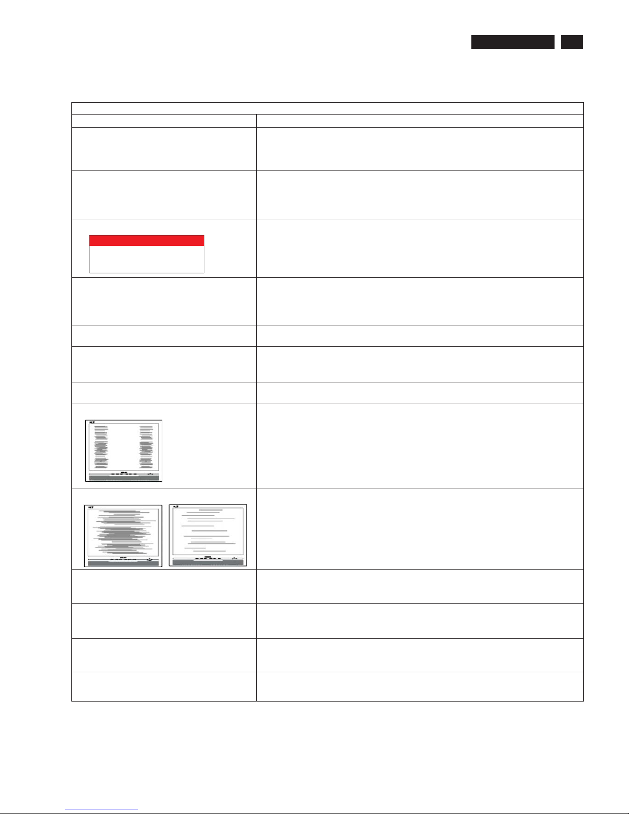
Troubleshooting
Common Problems
Having this problem
Check these items
No Picture
(Power LED not lit)
1.Make sure the power cord is plugged into the power outlet and into the back of the
monitor.
2.First, ensure that the power button on the front of the monitor is in the OFF position,
then press it to the ON position.
No Picture
(Power LED is amber or yellow)
1.Make sure the computer is turned on.
2. Make sure the signal cable is properly connected to your computer.
3.Check to see if the monitor cable has bent pins.
4.The Energy Saving feature may be activated
Screen says
1. Make sure the monitor cable is properly connected to your computer. (Also refer
to the Quick Set-Up Guide).
2.Check to see if the monitor cable has bent pins.
3. Make sure the computer is turned on.
AUTO button not working properly
1.The Auto Function is designed for use on standard Macintosh or IBM-compatible
PCs running Microsoft Windows.
2. It may not work properly if using nonstandard PC or video card.
Imaging Problems
Display position is incorrect
1.Press the Auto button.
2. Adjust the image position using the Horizontal Position and/or Vertical
Position in OSD Main Controls.
Image vibrates on the screen
Check that the signal cable is properly connected to the graphics board or PC.
Vertical flicker appears
1. Press the Auto button.
2. Eliminate the vertical bars using the More Settings of Phase/Clock in OSD Main
Controls.
Horizontal flicker appears
1. Press the Auto button.
2. Eliminate the vertical bars using the More Settings of Phase/Clock in OSD Main
Controls.
The screen is too bright or too dark
Adjust the contrast and brightness on OSD Main Controls. (The backlight of the
LCD monitor has a fixed life span. When the screen becomes dark or begins to
flicker, please contact your dealer).
An after-image appears
If an image remains on the screen for an extended period of time, it may be
imprinted in the screen and leave an afterimage. This usually disappears after a
few hours.
An after-image remains after the power
has been turned off.
This is characteristic of liquid crystal and is not caused by a malfunction or
deterioration of the liquid crystal. The after-image will disappear after a peroid
of time.
Green, red, blue, dark, and white dots
Remains
The remaining dots are normal characteristic of the liquid crystal used in
today's technology.
ATTENTION
CHECK CABLE CONNECTION
This page deals with problems that can be corrected by a user. If the problem still persists after you have tried thesesolutions, contact Philips
customer service representative.
6
190CW7 LCD
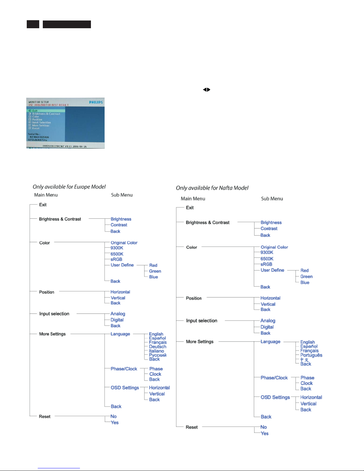
On Screen Display
Description of the On Screen Display
Basic and simple instruction on the control keys.
When you press "menu" button on the front control of your monitor, the On-Screen Display (OSD) Main Controls window will pop up and
you can then start making adjustments to your monitor's various features. Use the keys to make your adjustments.
This is a feature in all Philips LCD monitors. It allows an end user to adjust screen performance of the monitors directly through an
on-screen instruction window. The user interface provides userfriendliness and ease-of-use when operating the monitor.
The OSD Tree
Below is an overall view of the structure of the On-Screen Display. You can use this as a reference when you want to work your way around the
different adjustments later on.
7
190CW7 LCD
On Screen Display
8
190CW7 LCD
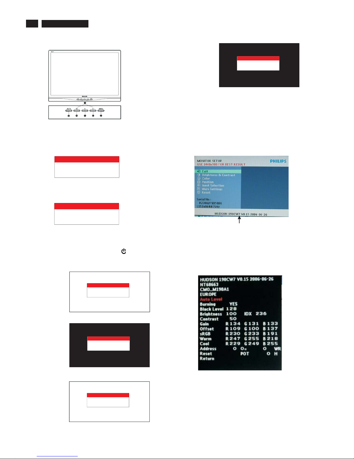
Lock/Unlock,Aging,Factory Mode
Front Control
To Lock/Unlock OSD FUNCTION(User Mode)
The OSD function can be locked by pressing"OK"button(1) for more
than 10 seconds, the screen shows following windows for 4 seconds.
Everytime when you press"OK" button, this message
appears on the screen automatically.
ATTENTION SIGNAL
OSD MAIN CONTROLS
LOCKED
Unlock OSD function
Unlocked OSD function can be released by pressing "OK" button for
more than 10 seconds again.
ATTENTION SIGNAL
OSD MAIN CONTROLS
UNLOCKED
After 15 seconds,
bring up:
----------
---------repeatly
Connect Signal cable again=> go back to normal display
After 15 seconds,
bring up:
After 15 seconds,
bring up:
Access Aging Mode
Step1:D
Step 2 : [Push "AUTO" & " MENU " buttons
at the same time and hold them]+[Press power " " button untill comes
out " AGING screen"] => then release all buttons.
Bring up:
isconnect Interface Cable between Monitor and PC.
Turn off LCD monitor.Then
Access Factory Mode
1). Turn off monitor.
2).
3).Press "MENU" button, wait until the OSD menu with
Characters "HUDSON 190CW7 V0.15 2006-06-26" (below OSD
menu) come on the Screen of the monitor.
[Push "AUTO" & "MENU" buttons at the same time and hold them]
+[Press "power" button untill comes out "Windows screen" ]
=> then release all buttons
Factory Mode indicator
Factory Menu
Cursor can move on gray color area
Hot key function: by pressing " LEFT " and " RIGHT " key
Simultaneously at User Mode (or Factory Mode)
(PS: The OffsetRGBfunction can be used on reduce or eliminate
snowy noise on the background when the resolution of video signal
is 1440*900 vertical 60Hz. Slightly increase or decrease the value
until snowy noise completely disappear.
ATTENTION
AGING...
ATTENTION
AGING...
ATTENTION
AGING...
ATTENTION
AGING...
ATTENTION
AGING...
ATTENTION
AGING...
9
190CW7 LCD
Philips' Flat Panel Monitors Pixel Defect Policy
Philips strives to deliver the highest quality products. We
use some of the industry's most advanced manufacturing
processes and practice stringent quality control. However,
pixel or sub pixel defects on the TFT LCD panels used in
flat panel monitors are sometimes unavoidable. No
manufacturer can guarantee that all panels will be free
from pixel defects, but Philips guarantees that any monitor
with an unacceptable number of defects will be repaired or
replaced under warranty. This notice explains the different
types of pixel defects and defines acceptable defect levels
for each type. In order to qualify for repair or replacement
under warranty, the number of pixel defects on a TFT LCD
panel must exceed these acceptable levels. For example,
no more than 0.0004% of the sub pixels on a 15" XGA
monitor may be defective. Furthermore, Philips sets even
higher quality standards for certain types or combinations
of pixel defects that are more noticeable than others. This
policy is valid worldwide.
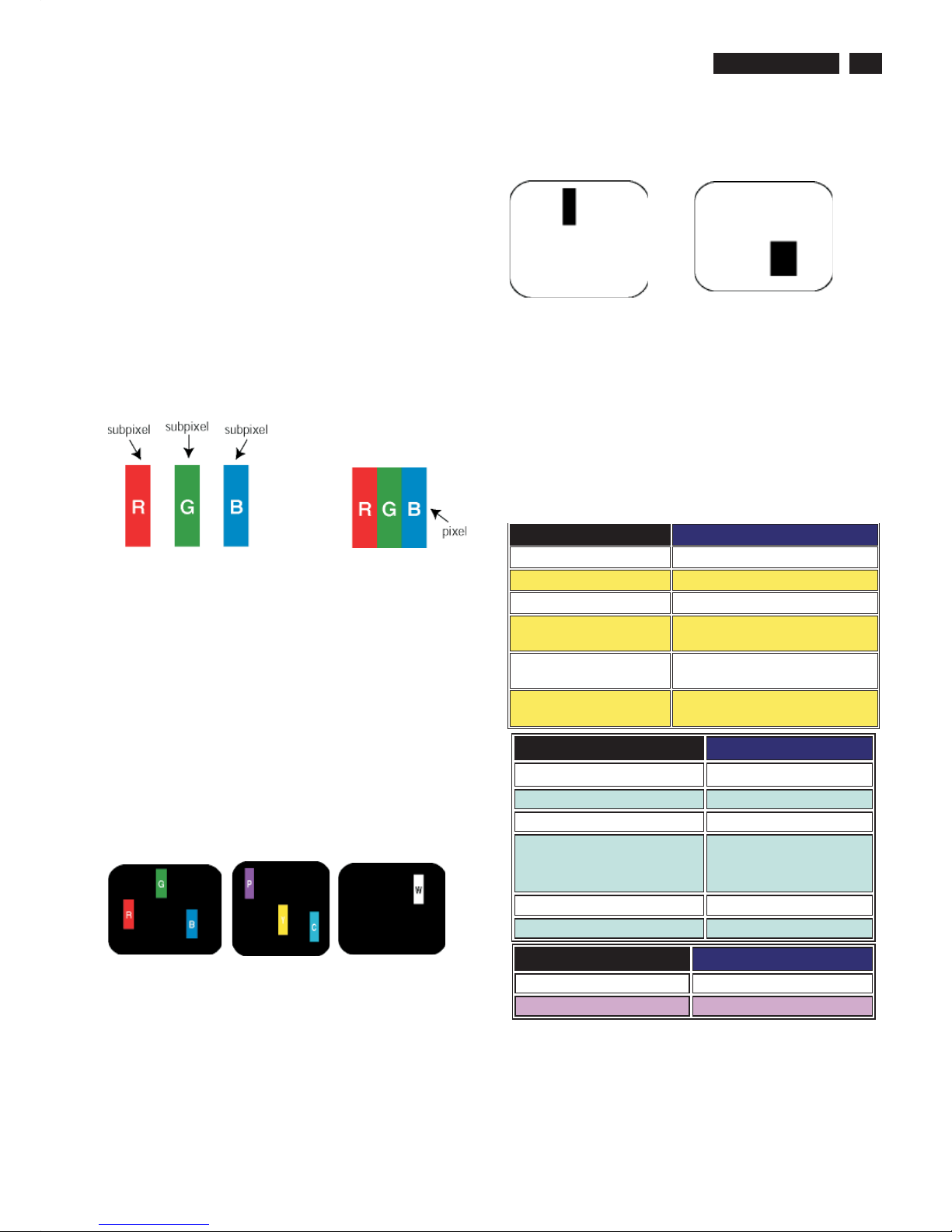
Pixels and Sub pixels
A pixel, or picture element, is composed of three sub pixels
in the primary colors of red, green and blue. Many pixels
together form an image. When all sub pixels of a pixel are lit,
the three colored sub pixels together appear as a single
white pixel. When all are dark, the three colored sub pixels
together appear as a single black pixel. Other combinations
of lit and dark sub pixels appear as single pixels of other
colors.
Types of Pixel Defects
Pixel and sub pixel defects appear on the screen in different
ways. There are two categories of pixel defects and several
types of sub pixel defects within each category. Bright dot
defects appear as pixels or sub pixels that are always lit or
'on'. These are the types of bright dot defects:
One lit red,
green or
blue sub pixel
Two adjacent lit
sub pixels:
- Red+ Blue =Purple
- Red+ Green =Yellow
- Green+ Blue =Cyan
(Light Blue)
Three adjacent lit
sub pixels
(one white pixel)
Black Dot Defects Black dot defects appear as pixels or sub
pixels that are always dark or 'off'. These are the types of black
dot defects:
One dark sub pixel Two or three adjacent dark sub pixels
Proximity of Pixel Defects
Because pixel and sub pixels defects of the same type that are
near to one another may be more noticeable, Philips also specifies
tolerances for the proximity of pixel defects.
Pixel Defect Tolerances
In order to qualify for repair or replacement due to pixel defects
during the warranty period, a TFT LCD panel in a Philips flat panel
monitor must have pixel or sub pixel defects exceeding the
tolerances listed in the following tables.
Note:
* 1 or 2 adjacent sub pixel defects = 1 dot defect
TOTAL DOT DEFECTS ACCEPTABLE LEVEL
MODEL 190CW7
Total bright or bl ack dot defe cts of all types 5orfewer
BRIGHT DOT DEFECTS ACCEPTABLE LEVEL
MODEL
190CW7
1 lit subpixel
3 or fewer
2 adjacent lit subpixels
1 or fewer
3 adjacent lit subpixels (one white
pixel)
0
Distance between two bright dot
defects*
Total bright dot defects of all types
BLACK DOT DEFECTS ACCEPTABLE LEVEL
MODEL
190CW7
1 dark subpixel 5 or fewer
2 adjacent dark subpixels 2 or fewer
3 adjacent dark subpixels(one white pixel) 0
Distance between two black dot defects* 15 mm or more
Total black dot defects of all types 5 or fewer
25mm or more
3 or fewer
Philips Pixel Defect Policy
10
190CW7 LCD
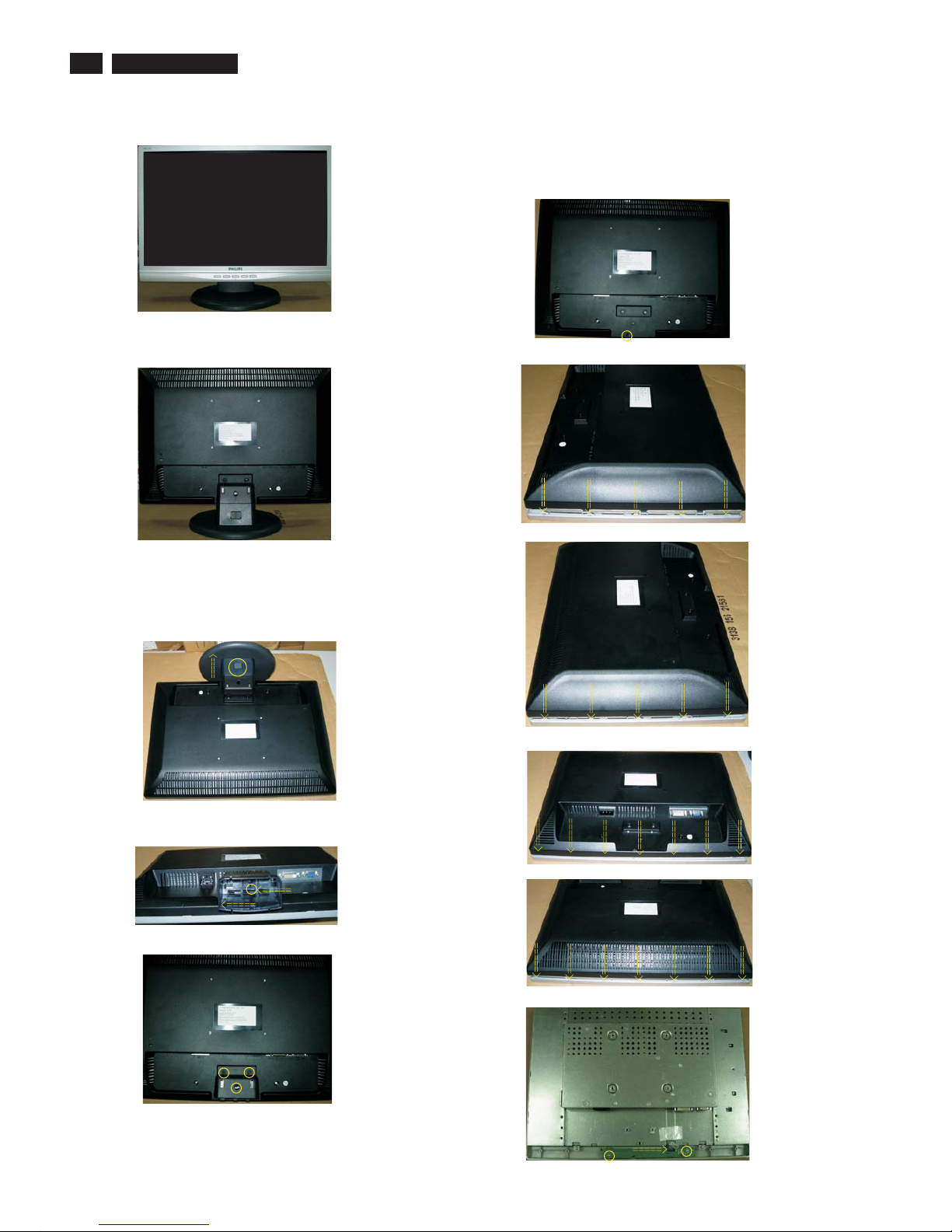
Mechanical Instruction
Front view
Back view
1. Remove .the base
Fig.8
Fig.2
Fig.1
Fig.11
Fig.9
Fig.10
2: Remove the Back Cover Assy
a. Unscrew 1 screws as shown in Fig.6.
b. Open 10 clicks on right and left side as shown in Fig.7 and Fig.8.
c. Open 7 clicks on bottom side as shown in Fig.9.
d. Open 7 clicks on top side as shown in Fig.10.
e. Remove the BACK COVER ASSY in Fig.11.
Fig.3
Fig.4
Fig.5
Fig.6
a: Place the monitor face down on a smooth surface as Fig.3.
Be carefully to prevent the scratch and injury during the
uninstallation. Press the botton and push the base as Fig.3.
b: Drag the click to left and slip the stand bottom to left at the same time
as Fig.4.
Fig.7
Botton
Base
c: Remove the three screws and remove the hinge and stand top as
Fig.5.
11
190CW7 LCD
Mechanical Instruction
In warranty, it is not allowed to disassembly the LCD panel, even the
backlight unit defect.
Out of warranty, the replacment of backlight unit is a correct way
when the defect is cused by backlight (CCFL,Lamp).
Fig. 17
Fig. 18
Fig. 19
Fig. 16
Fig.12
Fig.13
Fig.14
Fig.15
3. Remove the Key board and bezel.
a.
b. Unscrew the 2 screws to remove the bezel as Fig. 12.
Unscrew the 2 screws and disconnect the 1 cable to remove the
Key board as Fig.11.
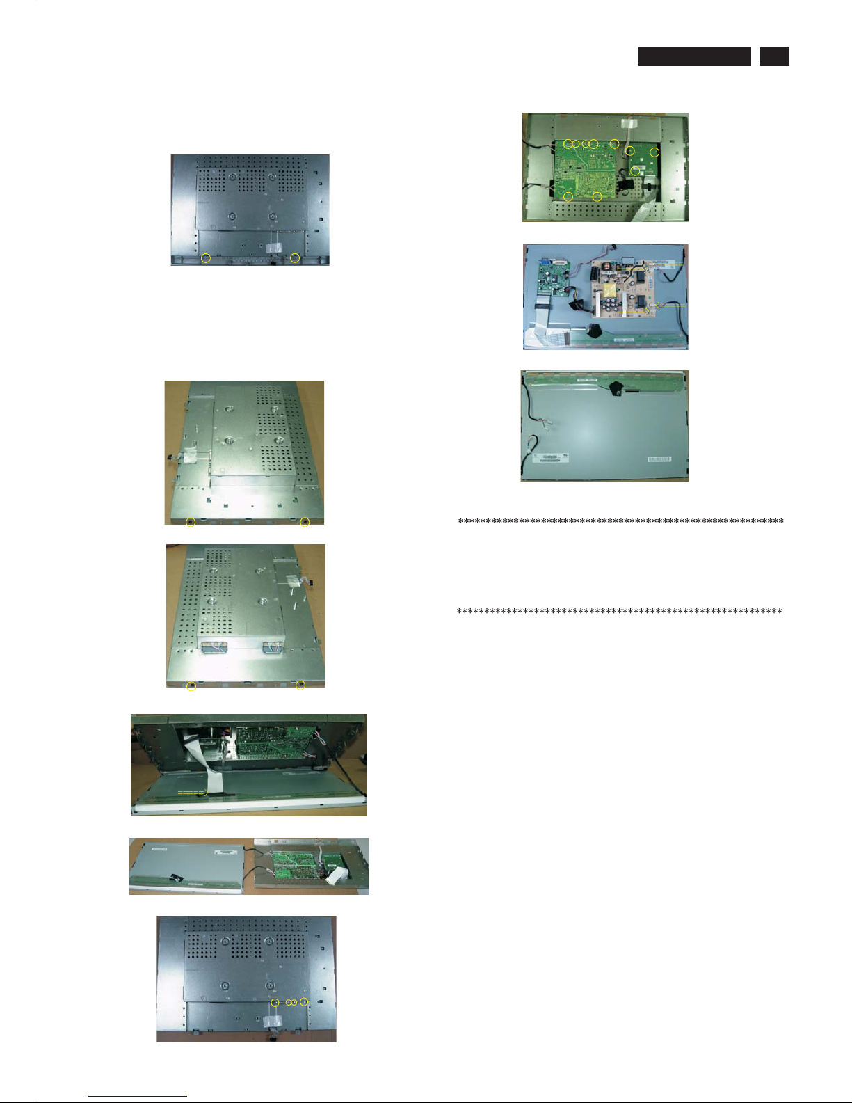
4. Remove the Scaler , Power board.
a.
b. Disconnect the 1 cable carefully and turn the SHIELDING ASSY to
right as Fig.15~16.
c. Unscrew the 14 screws to r
SHIELDING ASSY ,
Unscrew the 4 screws on left and right side as Fig.13~14.
emove the SHIELDING ASSY as
Fig. 17~18.
d. Disconnect the 4 cables to remove the Scaler and Power board.
Fig. 20
12
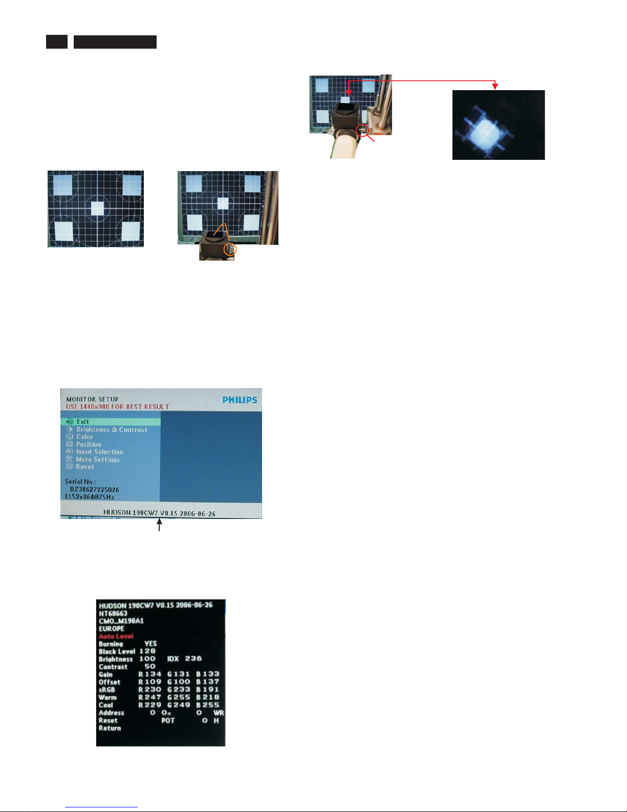
190CW7 LCD
Color Adjustment
Alignment procedure
1. Turn on the LCD monitor.
2.Turn on the Timing/pattern generator. See Fig.1
3. Preset LCD color Analyzer CA-110
-Remove the lens protective cover of probe CA-A30.
-Set measuring/viewing selector to measuring position for reset
analyzer.(zero calibration) as Fig.2
- Turn on the color analyzer (CA-110)
-Press 0-CAL button to starting reset analyzer.
Fig. 1
Fig. 2
Clear imageClear image
Measurement/viewing selectorMeasurement/viewing selector
Fig. 3
4). Press button, then select factory mode indicator by"MENU" "LEFT"
or "RIGHT" button .Press"MENU" button to bring up submenu
windows as below:
Fig.5
Cover (black)Cover (black)
Measurement viewing selectorMeasurement viewing selector
Fig. 4
Fig. 2
5.Display
Press "LEFT" or "RIGHT" button to select . Change the value
by "LEFT" or "RIGHT" key until the X,Y co-ordinates as below
4. Access Factory Mode
1). Turn off monitor.
2).
3).Press "MENU button, wait until the OSD menu with
Characters" HUDSON 190CW7 V0.15 2006-06-26" (below OSD
menu) come on the Screen of the monitor. as shown in Fig3.
[Push "AUTO" & "MENU" buttons at the same time and hold them]
+[Press "power" button untill comes out "Windows screen" ]
=> then release all buttons
"
Factory Mode indicator
5.1 White color adjustment
There are three factory preset white color 9300K, 6500K, sRGB.
Apply full white pattern, with brightness in 100 % position
and the contrast control at 50 % position.
The 1931 CIE Chromaticity (color triangle) diagram (x,y)
coordinate for the screen center should be:
Product spec.
9300K CIE coordinates X = 0.283 ± 0.02
Y = 0.297 ± 0.02
6500K/ sRGB CIE coordinates X = 0.313 ± 0.02
Y = 0.329 ± 0.02
sRGB CIE coordinates X = 0.313 ± 0.02
Y = 0.329 ± 0.02
Production alignment spec.
9300K CIE coordinates X = 0.283 ± 0.005
Y = 0.297 ± 0.005
6500K/ sRGB CIE coordinates X = 0.313 ± 0.005
Y = 0.329 ± 0.005
sRGB CIE coordinates X = 0.313 ± 0.005
Y = 0.329 ± 0.005
Quality Inspection spec.
9300K CIE coordinates X = 0.283 ± 0.015
Y = 0.297 ± 0.015
6500K/ sRGB CIE coordinates X = 0.313 ± 0.015
Y = 0.329 ± 0.015
sRGB CIE coordinates X = 0.313 ± 0.015
Y = 0.329 ± 0.015

13
190CW7 LCD
General FAQs
Q: When I install my monitor what should I do if the screen shows 'Cannot display this video
mode'?
A: Recommended video mode f or Philips 19 " : 1440 x 900 @60Hz.
1. Unplug all cables, then connect your PC to the monitor that you used previously.
2. In the Windows Start Menu, select Settings/Control Panel. In the Contr ol Panel Window, s elect the Display ic on. Inside the Display Control Panel,
select the 'Settings' tab. Under the setting tab, in box labeled 'desktop ar ea', mov e the slidebar to 1440 x 900 pixels ( 19").
3. Open 'Advanced Properties' and set the Refresh Rate to 60Hz, then click OK.
4. Restart your computer and repeat step 2 and 3 to verify that your PC is set at 1440 x 900@60Hz (19").
5. Shut down your computer, disconnect your old monitor and reconnect your Philips LCD monitor.
6. Turn on your monitor and then turn on your PC.
Q: Whatdoes'refreshrate'meaninconnectionwithanLCDmonitor?
A: The refresh rate is of much less relevance for LCD monitors. LCD monitors display a stable, flicker-free image at 60Hz. There is no visible
difference between 85Hz and 60Hz
Q: Wh at ar e the .inf an d .icm f iles o n th e CD-ROM? Ho w d o I i n stall the d r i vers (.inf and . i c m )?
A: These are the driv er files for your monitor. Follow the instructions in your us er manual to install the drivers. Your computer may ask you for monitor
drivers (.inf and . icm files) or a driv er disk when you first install your monitor. Follow the instructions to inser t the ( companion CD-ROM) included in
this package. Monitor drivers (.inf and . icm files) will be installed automatically.
Q: How do I adjust the resolution?
A: Your video card/graphic driver and monitor together deter mine the available resolutions. You can select the desired resolution under Windows®
Control Panel with the "Display properties".
Q: What if I get lost when I am makin g monitor adjustments?
A: Simply press the MENU button, then select 'Reset' to recall all of the original f actory settings.
Q: What is the Auto function?
A: The AUTO adjustment k ey restores the optimal screen position, phase and clock settings by pressing of a single button – without the need to
navigate through OSD (On Screen Display) menus and control keys.
Note: Auto function is available in selected models only.
Q: My Monitor has no power (Power LED does not light up). What should I do?
A: Make sure the AC power c ord is connected between the monitor and AC outlet, and click a key on keyboard/mouse to wake up the PC.
Q: Will the LCD monitor accept an interlaced signal under PC models?
A: No. If an Interlace signal is used, the screen displays both odd and even horizontal scanning lines at the same time, thus distorting the picture.
Q: Wh at d o es th e R efresh Rat e mean f or LCD?
A: Unlike CRT display technology, in which t he speed of the electron beam is swept from the top to the bottom of the screen det ermines flicker, an
active matrix display uses an active element (TFT) t o control each individual pixel and t he refresh rate is therefore not really applicable to LCD
technology.
Q: Will the LCD screen be resistant to scratches?
A: A protective coating is applied to the s urface of the LCD, which is durable to a certain extent (approximately up t o the hardness of a 2H pencil). In
general, it is recommended that the panel surface is not subject to any excessive shocks or scratches.
Q: How s h ould I c lean t he LCD surface?
A: For normal cleaning, use a clean, soft cloth. For extensive cleaning, please use isopropyl alcohol. Do not use other solvents such as ethyl alcohol,
ethanol, acetone,hexane, etc.
Q:Can I change the color setting of my monitor?
A:Yes, you can change your color setting through OSD control as the following procedures,
1. Press "MENU" to show the OSD (On Screen Display) menu.
2. Press "Left Arrow" to select the option "color" then press "MENU" to enter color setting, there are five settings as below.
a. 6500K; this setting features the panel closed to red-whit e color tone.
b. 9300K; this setting features the panel closed to blue-white color tone.
c. Original; this setting load the default panel setting in ter ms of color tone. (Not e: different panel maker may feature a different c olor t emperature*)
d. User Define; the user can choose his/ her pr eference color setting by adjusting red, green, blue color.
e. sRGB; this is a standard setting for ensuring c orrect exchange of c olors between different device (e.g. digital cameras, monit ors, printers,
scanners, etc.)
Q: Can the Philips LCD Monitor be mounted on the wall?
A: Yes. Philips LCD monitors have this optional feature. For standard VESA mount holes on the rear cover allows the user to mount the Philips
monitor on most of the VESA standard arms or accessories. We recommend to contact your Philips sales r epresentative for more information.
Screen A djustmen ts
Q: What is the FPadjust program on the CD-ROM?
A: The FPadjust program generates alignment patterns that help you adjust monitor settings such as C ontrast, Brightness, Horizontal Position,
Vertical Position, Phase and Clock for optimal performance.
Q: When I install my monitor, how do I get the best performance from the monitor?
A:1. For best performance, make sure your display s ettings are set at 1440 x 900@60Hz for 19". Note: You can check the current dis play settings
by pressing the OSD MENU button onc e. The curr ent display mode is shown in OSD first page.
FAQs (Frequently Asked Questions)

14
190CW7 LCD
FAQs (Frequently Asked Questions)
2. To install the Flat Panel Adjust (FPadjust) program located on the monitor setup CD-ROM, open the CD-ROM and double-click the FP_setup4.3.exe icon.
This will install FP Adjust automatically and place a shortcut on your desktop.
3. Run FPadjust by double clicking the shortcut. Follow the instructions step by step to optimize image performance with your system's video controller.
Q: How do LCDs compare to CRTs in terms of radiation?
A: Because LCDs do not use an electron gun, they do not generate the same amount of radiation at the screen surface.
Compatibility with other Peripherals
Q: Are Philips LCD monitors Plug-and-Play?
A: Yes, the monitors are Plug-and-Play compatible with Windows 95, 98, 2000 and XP.
Q: What i s USB (Un iver sal Ser ial Bus )?
A: Think of USB as a smart plug for PC peripherals. USB automatically determines resources (like driver software and bus bandwidth) required by peripherals.
USB makes necessary resources available without user intervention. There are three main benefits of USB. USB eliminates "case anxiety," the fear of
removing the computer case to install circuit board cards -- that often requires adjustment of complicated IRQ settings -- for add-on peripherals. USBdoes
away with "port gridlock." Without USB,PCs are normally limited to one printer, two Com port devices (usually a mouse and modem), one Enhanced Parallel
Port add-on (scanner or video camera, for example), and a joystick. More and more peripherals for multimedia computers come on the market every day.
With USB, up to 127 devices can run simultaneously on one computer. USB permits "hot plug-in." No need to shut down, plug in, reboot and run set up to
install peripherals. No need to go through the reverse process to unplug a device. Bottom line: USB transforms today's "Plug-and-Pray" into true
Plug-and-Play! Please refer to glossary for more information about USB.
Q: What is a USB h ub ?
A: A USB hub provides additional connections to the Universal Serial Bus. A hub's upstream port connects a hub to the host, usually a PC. Multiple
downstream ports in a hub allows connection to another hub or device, such as a USB keyboard, camera or printer.
LCD Panel Technology
Q: What is a Liquid Crystal Display?
A: A Liquid Crystal Display (LCD) is an optical device that is commonly used to display ASCII characters and images on digital items such as watches,
calculators, portable game consoles, etc. LCD is the technology used for displays in notebooks and other small computers. Like light-emitting diode and
gas-plasma technologies, LCD allows displays to be much thinner than cathode ray tube(CRT) technology.LCD consumes much less power than LED and
gas-displays because it works on the principle of blocking light rather than emitting it.
Q: What differentiates passive matrix LCDs from active matrix LCDs?
A: An LCD is made with either a passive matrix or an active matrix display grid. An active matrix has a transistor located at each pixel intersection, requiring
less current to control the luminance of a pixel. For this reason, the current in an active matrix display can be switched on and off more frequently, improving
the screen refresh time (your mouse pointer will appear to move more smoothly across the screen, for example). The passive matrix LCD has a grid of
conductors with pixels located at each intersection in the grid.
Q: What are the advant ages of TFT LCD comp ared w ith CRT?
A: In a CRT monitor, a gun shoots electrons and general light by colliding polarized electrons on fluorescent glass. Therefore, CRT monitors basically operate
with an analog RGB signal. A TFT LCD monitor is a device that displays an input image by operating a liquid crystal panel. The TFT has a fundamentally
different structure than a CRT: Each cell has an active matrix structure and independent active elements. A TFT LCD has two glass panels and the space
between them is filled with liquid crystal. When each cell is connected with electrodes and impressed with voltage, the molecular structure of the liquid
crystal is altered and controls the amount of inlet lighting to display images. A TFT LCD has several advantages over a CRT, since it can be very thin and no
flickering occurs because it does not use the scanning method.
Q: Why is vertical frequency of 60Hz optimal for an LCD monitor?
A: Unlike a CDT monitor, the TFT LCD panel has a fixed resolution. For example, an XGA monitor has 1024x3 (R, G, B) x 768 pixels and a higher resolution
may not be available without additional software processing. The panel is designed to optimize the display for a 65MHz dot clock, one of the standards for
XGA displays. Since the
Q: What kind of wide-angle technology is available? How does it work?
A: The TFT LCD panel is an element that controls/displays the inlet of a backlight using the dual-refraction of a liquid crystal. Using the property that the
projection of inlet light refracts toward the major axis of the liquid element, it controls the direction of inlet light and displays it. Since the refraction ratio of
inlet light on liquid crystal varies with the inlet angle of the light, the viewing angle of a TFT is much narrower than that of a CDT. Usually, the viewing angle
refers to the point where the contrast ration is 10. Many ways to widen the viewing angle are currently being developed and the most common approach is to
use a wide viewing angle film, which widens the viewing angle by varying the refraction ratio. IPS (In Plane Switching) or MVA (Multi Vertical Aligned) is
also used to give a wider viewing angle.
Q: Why is there no flicker on an LCD Monitor?
A: Technically speaking, LCDs do flicker, but the cause of the phenomenon is different from that of a CRT monitor -- and it has no impact of the ease of
viewing. Flickering in an LCD monitor relates to usually undetectable luminance caused by the difference between positive and negative voltage. On
the other hand, CRT flickering that can irritate the human eye occurs when the on/off action of the fluorescent object becomes visible. Since the reaction
speed of liquid crystal in an LCD panel is much slower, this troublesome form of flickering is not present in an LCD display.
Q: Why is an LCD monitor virtually low of Electro Magnetic Interference?
A: Unlike a CRT, an LCD monitor does not have key parts that generate Electro Magnetic Interference, especially magnetic fields. Also, since an LCD
display utilizes relatively low power, its power supply is extremely quiet.
Ergonomics, Ecology and Safety Standards
Q: What is t he CE m ark ?
A: The CE (Conformite Europeenne) mark is required to be displayed on all regulated products offered for sale on the European market. This 'CE' mark
means that a product complies with the relevant European Directive. A European Directive is a European 'Law' that relates to health, safety, environm
ent
and consumer protection, much the same as the U.S. National Electrical Code and UL Standards.
Q: Does the LCD monito r c onform t o g ener al s afet y s tandards?
A: Yes. Philips LCD monitors conform to the guidelines of MPR-II and TCO 99/03 standards for the control of radiation, electromagnetic waves, energy
reduction, electrical safety in the work environment and recyclability. The specification page provides detailed data on safety standards.
15
190CW7 LCD
Electrical Instructions
1 Electrical characteristics
1.1 Interface signals
1). D-Sub Analog
Input signal : Video, Hsync., Vsync
Video : 0.7 Vp-p, input impedance, 75 ohm @DC
Sync. : Separate sync TTL level , input impedance 2.2k ohm terminate
Hsync Positive/Negative
Vsync Positive/Negative
Composite sync TTL level, input impedance 2.2k ohm terminate(Positive/Negative)
Sync on green video 0.3 Vp-p Negative (Video 0.7 Vp-p Positive)
2). Intel DVI Digital
Input signal : Four channel TMDS signal
1.2 Interfac e
1.2.1 D-Sub Cabl e
Length : 1.8 M +/- 50 mm (fixed) , fix in monitor and with transplant pin protect cover.
Connector type : D-Sub male with DDC2B pin assignments.
Blue connector thumb-operated jack screws
1.3 Timing requirement
1.3.1 Mode storing capacity
Factory preset modes : 20
Preset modes : 40
User define modes : 24
Note: 1. Screen displays perfect picture at 17 factory-preset modes.
1.3.2Factor y preset mo des (20 m odes)
Item H.Freq. Mode Resolution V.Freq. Item H.Freq. Mode Resolution V.Freq
1 31.469 DOS 720x400 70.087 11 60.023 VESA 1024x768 75.029
2 31.469 VESA 640x480 59.940 12 67.500 VESA 1152x864 75.000
3 37.861 VESA 640x480 72.809 13 47.712 VESA 1360x768 60.015
4 37.500 VESA 640x480 75.000 14 55.935 VESA 1440x900 59.887
5 35.156 VESA 800x600 56.250 15 70.635 VESA 1440x900 74.984
6 37.879 VESA 800x600 60.317 16 35.000 MACINTOSH 640x480 67.000
7 48.077 VESA 800x600 72.188 17 49.700 MACINTOSH 832x624 75.000
8 46.875 VESA 800x600 75.000 18 60.000 VESA 1280x960 60.000
9 48.363 VESA 1024x768 60.004 19 79.976 VESA 1280x1024 75.025
10 56.476 VESA 1024x768 70.069 20 64.744 VESA 1400x1050 59.948

16
190CW7 LCD
Electrical Instructions
2 White color adjustment
There are three factory preset white color 9300K, 6500K, sRGB. Apply full white pattern, with brightness in 100 % position
and the contrast control at 50 % position. The 1931 CIE Chromaticity (color triangle) diagram (x,y) coordinate for the screen center
should be:
Product spec.
9300K CIE coordinates X = 0.283 ± 0.02
Y = 0.297 ± 0.02
6500K/ sRGB CIE coordinates X = 0.313 ± 0.02
Y = 0.329 ± 0.02
sRGB CIE coordinates X = 0.313 ± 0.02
Y = 0.329 ± 0.02
Production alignment spec.
9300K CIE coordinates X = 0.283 ± 0.005
Y = 0.297 ± 0.005
6500K/ sRGB CIE coordinates X = 0.313 ± 0.005
Y = 0.329 ± 0.005
sRGB CIE coordinates X = 0.313 ± 0.005
Y = 0.329 ± 0.005
Quality Inspection spec.
9300K CIE coordinates X = 0.283 ± 0.015
Y = 0.297 ± 0.015
6500K/ sRGB CIE coordinates X = 0.313 ± 0.015
Y = 0.329 ± 0.015
sRGB CIE coordinates X = 0.313 ± 0.015
Y = 0.329 ± 0.015
17
190CW7 LCD
Pin No. Description
1 T.M.D.S. data2-
2 T.M.D.S. data2+
3 T.M.D.S. data2 shield
4 No Connect
5 No Connect
6 DDC clock
7 DDC data
8 No Connect
9 T.M.D.S. data1-
10 T.M.D.S. data1+
11 T.M.D.S. data1 shield
12 No Connect
13 No Connect
14 +5V Power
15 Ground (for +5V) - Cable detect
16 Hot plug detect
17 T.M.D.S. data0-
18 T.M.D.S. data0+
19 T.M.D.S. data0 shield
20 No Connect
21 No Connect
22 T.M.D.S clock shield
23 T.M.D.S. clock+
24 T.M.D.S. clock-
General
DDC Data Re-programming
In case the DDC data memory IC or main EEPROM which storage all
factory settings were replaced due to a defect, the serial numbers have
to be re-programmed "Analog DDC IC, Digital DDC IC & EEPROM".
It is advised to re-soldered DDC IC and main EEPROM from the old
board onto the new board if circuit board have been replaced, in this case
the DDC data does not need to be re-programmed.
Additional information
Additional information about DDC (Display Data Channel) may be
obtained from Video Electronics Standards Association (VESA).
Extended Display Identification Data(EDID) information may be also
obtained from VESA.
1. An i486 (or above) personal computer or compatible.
2. Microsoft operation system Windows 95/98 .
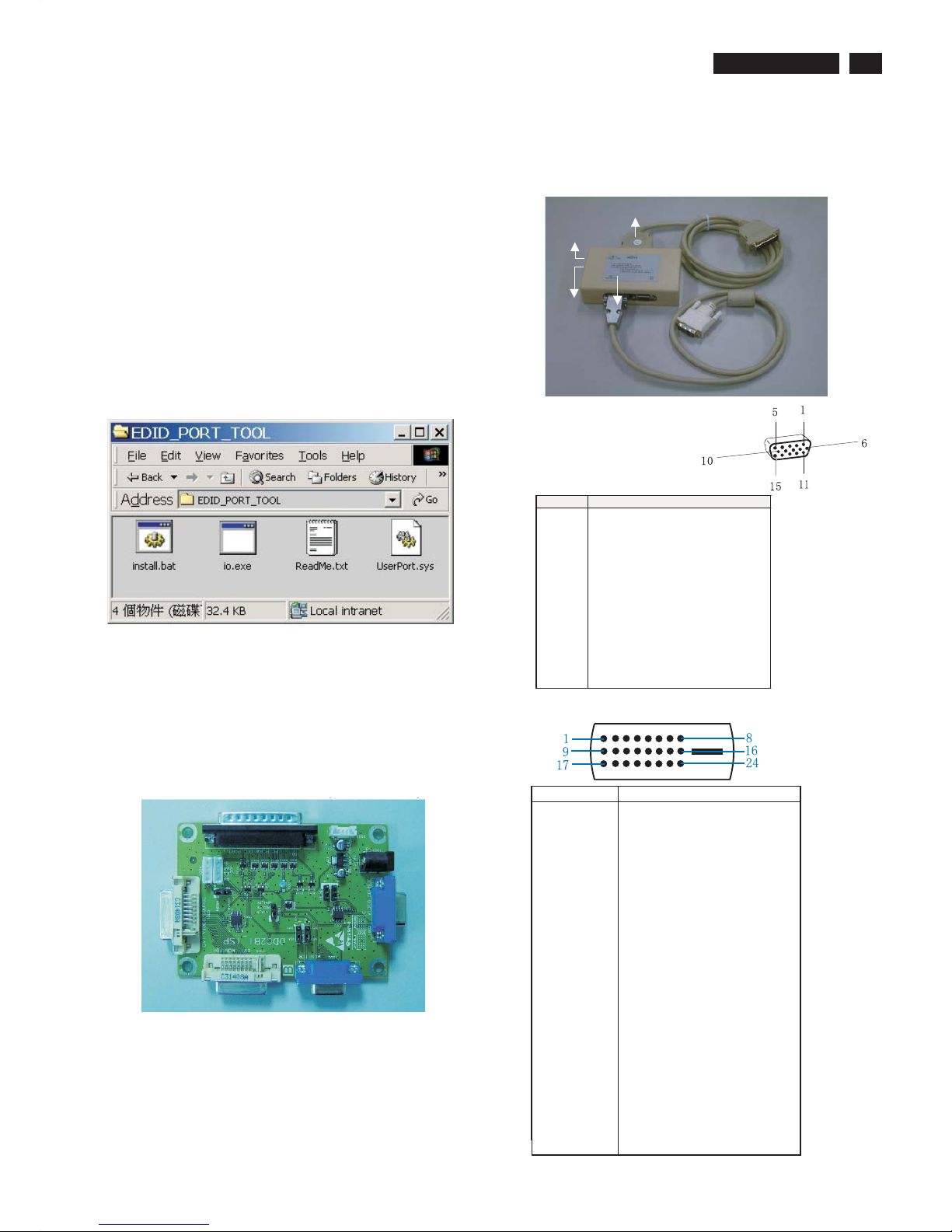
Y o Install the EDID_PORT_Tool under Win2000/XP . As
Fig. 1 .
A. Cody the "UserPort.sys" to C:\WINNT\system32\drivers(win2000)
C:\WINDOWS\system32\drivers(winXP)
B. Running " io.exe" everytime, Before you start to programming
edid data .
4. A/D Alignment kits (12NC: 3138 106 10396):
inclusion : a. Alignment box x1 (Fig. 2)
b. Printer cable x1
c. (D-Sub) to (D-Sub) cable x1
D. (D-Sub) to (DVI) cable x1
System and equipment requirements
ou have t
3. EDID46.EXE program
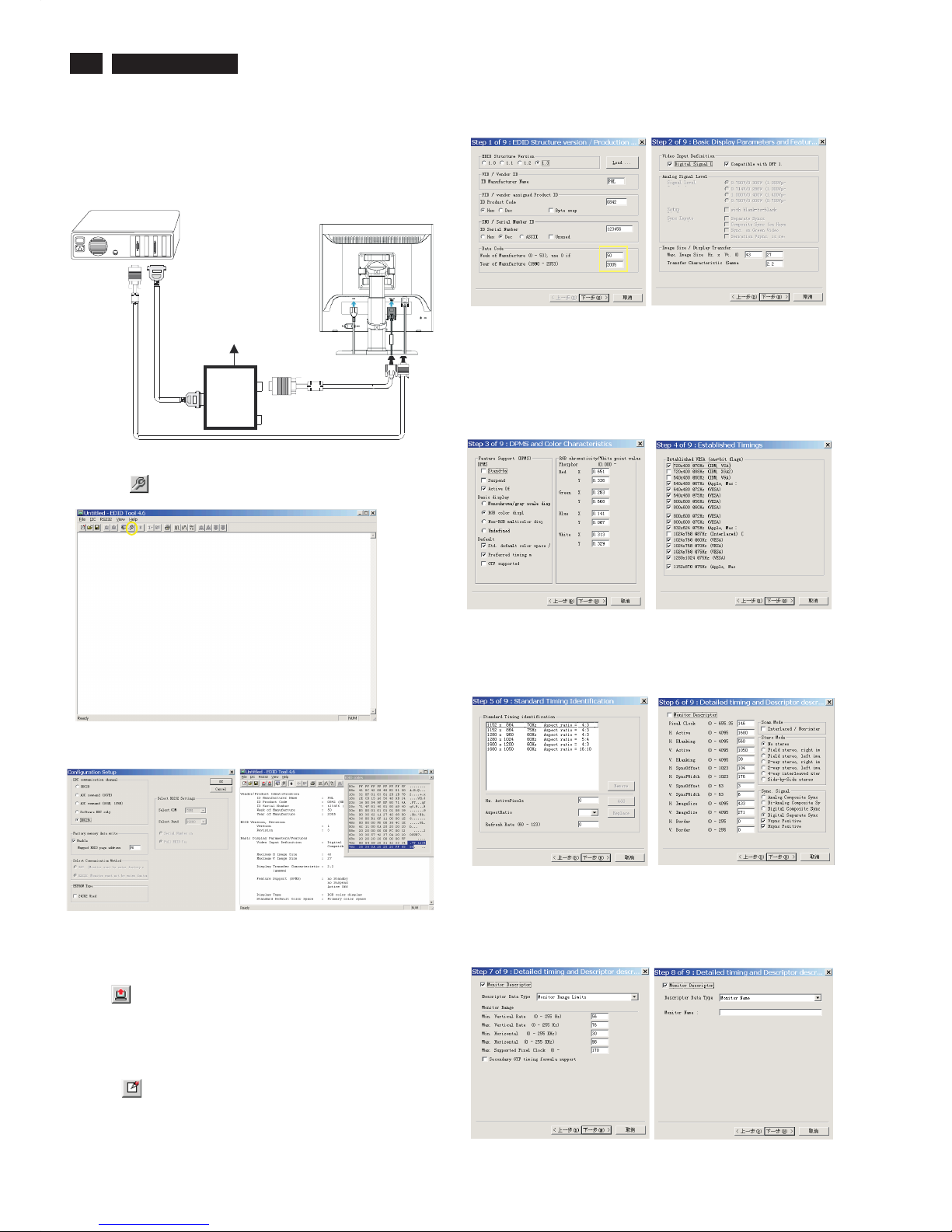
Fig. 1
Fig. 1
Fig. 2
To Monitor
D-sub/DVI cable
DC 8~12V
To Printer port
Power
indicator
Note: The alignment box has already build-in a batteries socket for
using batteries (8~12V) as power source. Pull out the socket by
remove four screws at the rear of box. Please do not forget that
remove batteries after programming. The energy of batteries can
only drive circuits for a short period of time.
PIN No. SIGNAL
1 Red video input
2 Green video input / sync on green
3 Blue video input
4GND
5 GND - Cable detect
6RedvideoGND
7 Green video GND
8 Blue video GND
9DDC+3.3Vor+5V
10 Logic GND
11 GND
12 Serial data line (SDA)
13 H-sync / H+V
14 V-sync
15 Data clock line (SCL)
Pin assignment
A. 15-pin D-Sub Connector
B. Input DVI -D Connector pin
Fig. 3
DDC Instructions
18
190CW7 LCD
DDC Instructions
Step 3: Installation of EDID46.EXE
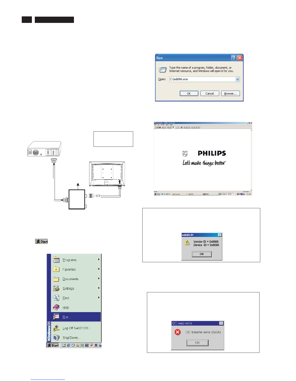
Method 1: Start on DDC program
Start Microsoft Windows.
1. The Program"EDID46.EXE" in service manual cd-rom be copyed to C:\ .
2. Click , choose Run at start menu of Windows as shown
In Fig. 5.
Fig. 5
4. Click OK button. The main menu appears (as shown in Fig. 7).
This is for initialize alignment box.
Fig. 7
Fig. 6
3. At the submenu, type the letter of your computer's hard disk drive
followed by :EDID46 (for example, C:\EDID46, as shown in Fig. 6).
Note 2: During the loading, EDID46 will verify the EDID data which just
loaded from monitor before proceed any further function, once
the data structure of EDID can not be recognized, the following
error message will appear on the screen as below. Please
confirm following steps to avoid this message.
1. The data structure of EDID was incorrect.
2. DDC IC that you are trying to load data is empty.
3. Wrong communication channel has set at configuration setup
windows.
4. Cables loosed or poor contact of connection.
1
Fig. 8
Note 1: If the connection is improper, you will see the following error
message (as shown in Fig. 8) before entering the main menu.
Meanwhile, the (read EDID) function will be disable. At this
time, please make sure all cables are connected correctly and
fixedly, and the procedure has been performed properly.
Fig. 9
Configuration and procedure
There is no Hardware DDC (DDC IC) anymore. Main EEPROM stores
all factory settings and DDC data (EDID code) which is also called
Software DDC. The following section describes the connection and
procedure for Software DDC application. The main EEPROM can be reprogrammed by enabling '' factory memory data write'' function on the
DDC program (EDID46.EXE).
Initialize alignment box
In order to avoid that monitor entering power saving mode due
to sync will cut off by alignment box, it is necessary to initialize
alignment box before running programming software
(EDID46.EXE). Following steps show you the procedures and
connection.
Step 1: Supply 8-12V DC power source to the Alignment box by
plugging a DC power cord .
Step 2: Connecting printer cable and D-Sub cable of monitor as Fig. 4
Fig. 4
PC
1= Power connector
2= D-SUB connector
To printer port (LTP1)
DC Power
8-12 V
Printer
Port
To
Monitor
To P C
1
2
----->
----->
19
190CW7 LCD
DDC Instructions
Step 3: Modify DDC data (verify EDID version, week,
year)
Click (new function) icon from the tool bar, bring up
Step 1 of 9 as shown in Fig. 14 .
EDID46 DDC application provides the function selection and
Step 4: Modify DDC data (Monitor Serial No.)
1. Click Next , bring up Fig. 15.
3. Click OK button to confirm your selection.
4. Click icon (Read EDID function) to read DDC EDID data from
monitor. The EDID codes will display on screen as shown in Fig. 13.
Fig. 15
2. Select the DDC2Bi as the communication channel.
As shown in Fig. 12.
Fig. 12
Fig. 13
Fig. 14
Select and fill out,
If necessary.
Re-programming Analog DDC IC
Step 1: After initialize alignment box, connecting all
cables and box as shown in Fig. 10.
Step 2: Read DDC data from monitor
1. Click icon as shown in Fig. 11 from the tool bar to bring up
the Channels "Configuration Setup" windows as shown in Fig. 11.
Fig. 10
1=Power connector
2= D-S UB connector
PC
To printer port (LTP1)
DC Power
8-12V
Printer
Port
To
Monitor
To PC
1
2
----->
----->
To PC Video port (D-sub)
Click this button
=====>
Fig. 11
20
190CW7 LCD
DDC Instructions
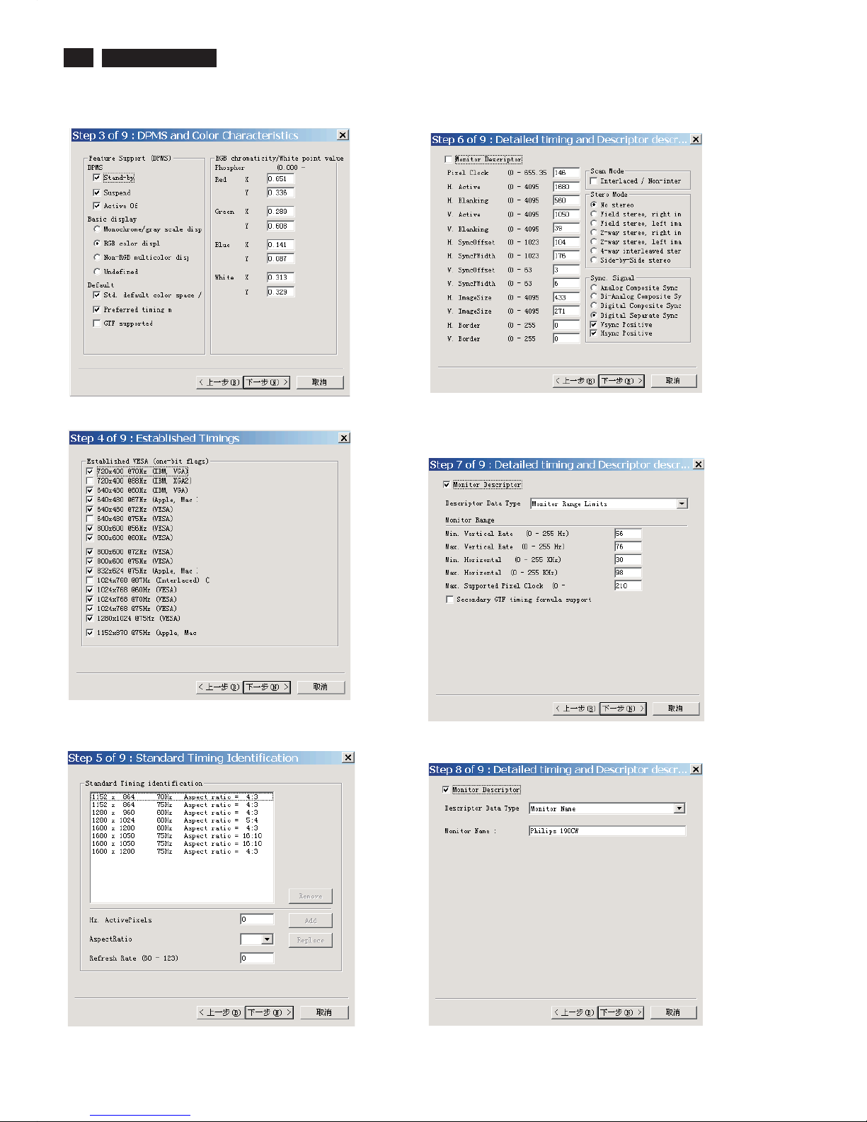
Fig. 21
Fig. 18
Fig. 19
7. Click Next , bring up Fig. 21.
4. Click Next , bring up Fig.18.
5. Click Next , bring up Fig.19.
6. Click Next , bring up Fig. 20.
In this step, please confirm the Descriptor Data Type is
Monitor Range Limits, and all the items are same as below.
Fig. 20
2. Click Next , bring up Fig.16.
Fig. 16
Fig. 17
3. Click Next , bring up Fig.17.
21
190CW7 LCD
DDC Instructions
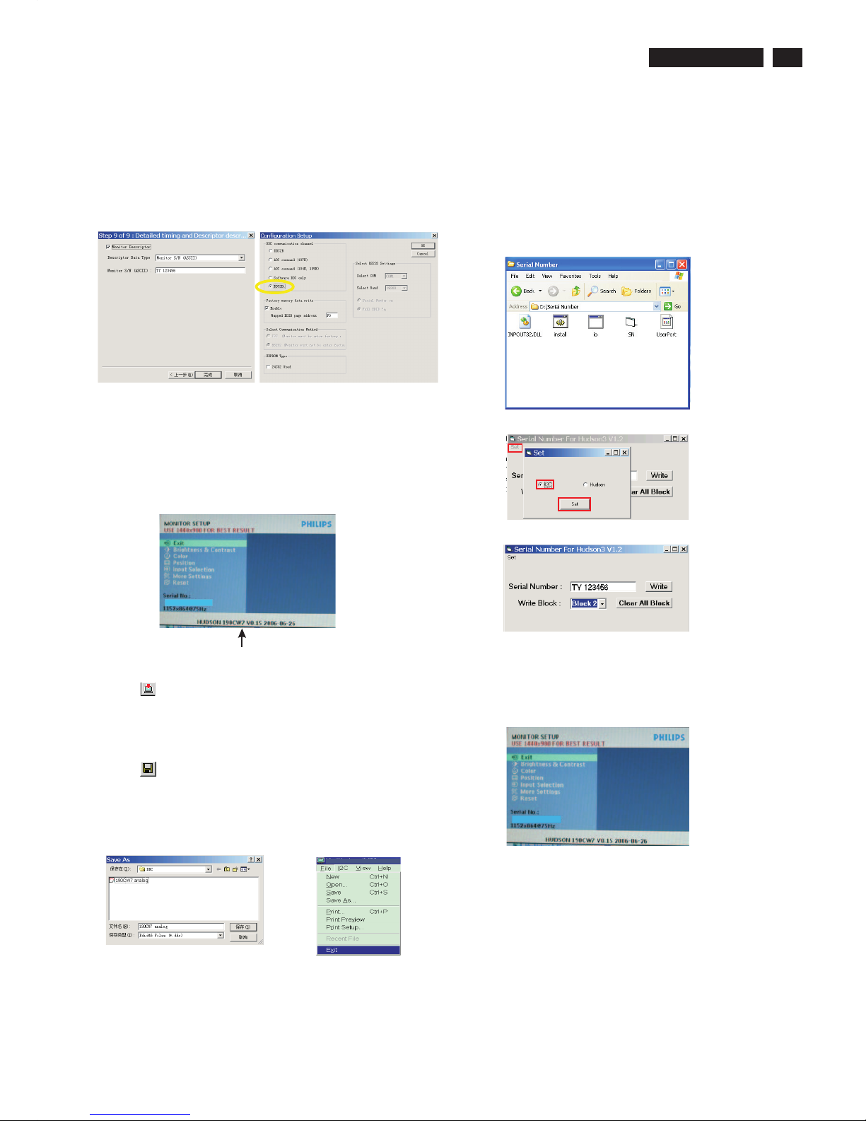
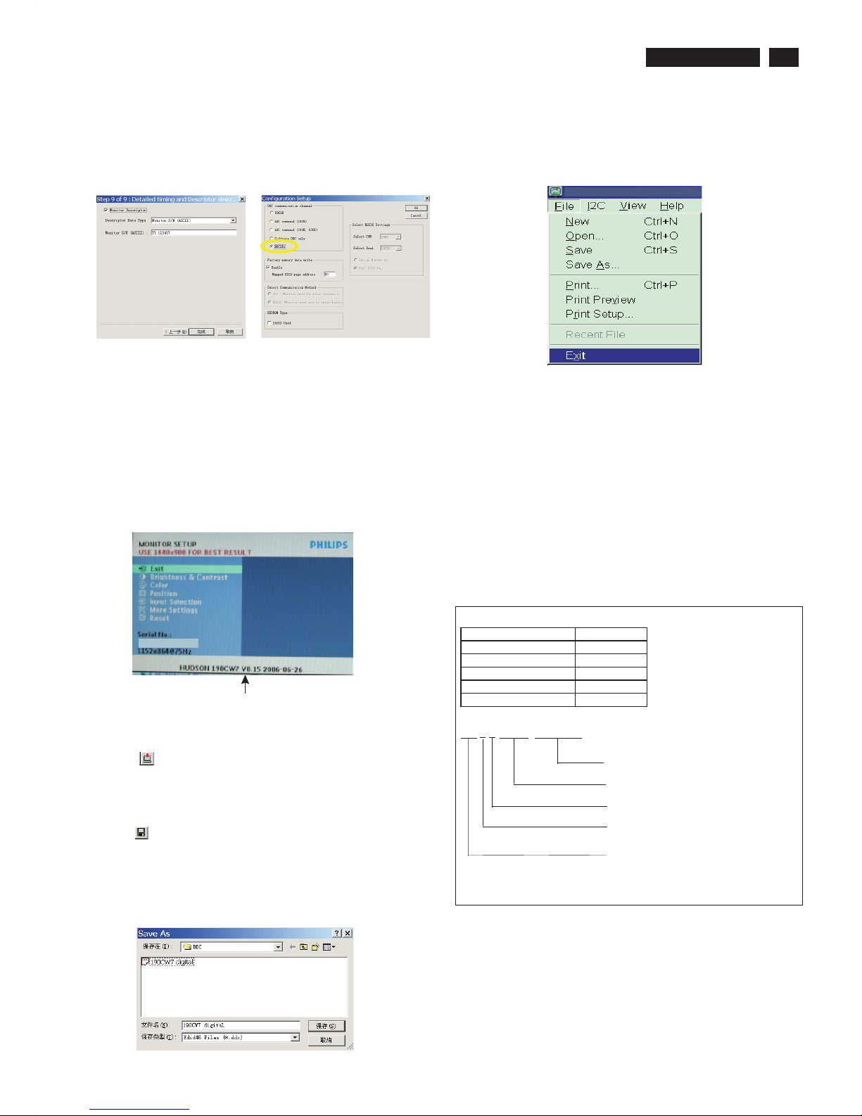
4). Click (Write EDID) icon from the tool bar to write DDC data.
Then wait for 20-30 seconds ,DDC data will be finished Writing.
Fig. 24
3) Push Menu to exit OSD menu.""
Fig. 22
8. Click Next , bring up Fig. 22.
- Click Finish to exit the Step window.
- Serial number can be filled up at this moment (for example, TY
123456).
NOTE: You must modify the Serial NO. In step 9, otherwise the Serial
NO. In OSD Couldn't be modified correctly.
Step 5: Write DDC data
1. Configuration should be as Fig. 23. And press OK.
Fig. 23
2. Click Save.
Step 7: Exit DDC program
Pull down the File menu and select Exit as shown in Fig. 26.
Step 6: Save DDC data
Sometimes, you may need to save DDC data as a text file for
using in other IC chip. To save DDC data, follow the steps below:
1. Click (Save) icon (or click "file"-> "save as") from the tool bar
and give a file name as shown in Fig. 25.
The file type is EDID46 file (*.ddc) which can be open in WordPad.
By using WordPad, the texts of DDC data & table (128 bytes, hex
code) can be modified. If DDC TEXTS & HEX Table ar completely
correct, it can be saved as .ddc flie to re-load it into DDC IC for DDC
Data application.
Fig. 26
Fig. 25
2. Access Factory Mode
1). Turn off monitor.
2).
3).Press "MENU" button, wait until the OSD menu with Characters
"HUDSON 190CW7 V0.15 2006-06-26" (below OSD menu) come
on the Screen of the monitor. as shown in Fig24.
[Push "AUTO" & "MENU" buttons at the same time and hold them]
+[Press "power" button untill comes out "Windows screen" ]
=> then release all buttons
Factory Mode indicator
Step9:
1. Disconnect the monitor power cord and connect it again.
2. Press the OK button to bring up the OSD main manu.
3. Re-confirm the serial Number is updated as shown in Fig.30.
Step 8: Modify serial number in OSD
1. Unzip the serial number.zip to your computer, then open the folder
as shown in Fig.27.
2. If use Win98 OS, you can execute SN.exe directly.
If use Win2000 or XP OS, first, you must execute install.bat, then
execute SN.exe
3. Set I2C bus(press the left-top button of operating window) as shown
in Fig.28, then press " SET" button.
4. Set Block2 as shown in Fig.29
5. key in new serial number, then press " Write" button as shown in
Fig.29 , Click " WRITE" button.
6. It will appear "Serial Number Write OK" , Click "Enter" to finish it.
Fig.27
Fig.28
Fig.29
Fig.30
TY 123456
TY 123456
22
190CW7 LCD
DDC Instructions
Step 3: Modify DDC data (verify EDID version, week,
year)
Click (new function) icon from the tool bar, bring up
Step 1 of 9 as shown in Fig. 35 .
EDID46 DDC application provides the function selection and
text change (select & fill out) from Step 1 to Step 9.
Step 4: Modify DDC data (Monitor Serial No.)
1. Click Next , bring up Fig. 36.
3. Click OK button to confirm your selection.
4. Click icon (Read EDID function) to read DDC EDID data from
monitor. The EDID codes will display on screen as shown in Fig. 34.
Fig. 36
2. Select the DDC2Bi as the communication channel.
As shown in Fig. 33.
Fig. 33
Fig. 34
Fig. 35
Select and fill out,
If necessary.
Re-programming Digital DDC IC
Step 1: After initialize alignment box, connecting all
cables and box as shown in Fig. 31.
Fig. 32
Step 2: Read DDC data from monitor
1. Click icon as shown in Fig. 11 from the tool bar to bring up
the Channels "Configuration Setup" windows as shown in Fig. 32.
Fig. 31
Click this button
=====>
D-sub to DVI-D cable
1=DVI-D connector
2=D-sub connector
3=Power Plug
2
1
3
D-sub cable
DC Power
8 12V
~
PC
To video card
To printer port (LTP1)
To
Monitor
Printer
Port
Fig. 42
Fig. 39
Fig. 40
7. Click Next , bring up Fig. 42.
4. Click Next , bring up Fig. 39.
5. Click Next , bring up Fig. 40.
6. Click Next , bring up Fig. 41.
In this step, please confirm the Descriptor Data Type is
Monitor Range Limits, and all the items are same as below.
Fig. 41
2. Click Next , bring up Fig. 37.
Fig. 37
Fig. 38
3. Click Next , bring up Fig. 38.
Philips190CW
23
190CW7 LCD
DDC Instructions
3. Click (Write EDID) icon from the tool bar to write DDC data.
Then wait for 20-30 seconds ,DDC data will be finished Writing.
Fig. 45
Fig. 43
8. Click Next , bring up Fig. 43.
- Click Finish to exit the Step window.
- Serial number can be filled up at this moment (for example, TY
123456).
NOTE: You must modify the Serial NO. In step 9, otherwise the Serial
NO. In OSD Couldn't be modified correctly.
Step 5: Write DDC data
1. Configuration should be as Fig. 40. And press OK.
Fig. 44
2. Click Save.
Step 7: Exit DDC program
Pull down the File menu and select Exit as shown in Fig. 47.
Step 8: Turn off the monitor, exit the factory mode.
Fig. 47
3) Push Menu to exit OSD menu.""
Fig.46
Sometimes, you may need to save DDC data as a text file for using
in other IC chip. To save DDC data, follow the steps below:
1. Click (Save) icon (or click "file"-> "save as") from the tool bar and
give a file name as shown in Fig. 46.
The file type is EDID46 file (*.ddc) which can be open in WordPad. By
using WordPad, the texts of DDC data & table (128 bytes, hex
code) can be modified. If DDC TEXTS & HEX Table ar completely
correct, it can be saved as *.ddc flie to re-load it into DDC IC for DDC
Data application.
Step 6: Save DDC data
Factory Mode indicator
Serial Number Definition
BOM Code
Panel Supplier CODE
AUO 1
CPT 2
LPL(LG) 3
QDI 4
CMO 5
BZ1A0625000001
SERIAL NO
YEAR/WEEK
SERVICE VERSION CHANGE CODE
BOM CODE(BILL OF MATERIAL)CODE
SITE CODE(PRODUCTION CENTER)
BZ CODE(AR-CZECH REPUBLIC
VN-HUNGARY(SZR),BZ-SUZHOU
DS-DONGGUAN)
2. Access Factory Mode
1). Turn off monitor.
2).
3).Press "MENU" button, wait until the OSD menu with Characters
"HUDSON 190CW7 V0.15 2006-06-26" (below OSD menu) come
on the Screen of the monitor. as shown in Fig24.
[Push "AUTO" & "MENU" buttons at the same time and hold them]
+[Press "power" button untill comes out "Windows screen" ]
=> then release all buttons
TY 123456

24
190CW7 LCD
DDC DATA
THE DISPLAY DATACHANNEL (DDC_2B) CONTENT INCLUDING:
(FOR 190CW7 ANALOG FOR CMO PANEL)
**********************************************************************
EDID log file
**********************************************************************
Vendor/Product Identification
ID Manufacturer Name : PHL
ID Product Code : 084A(HEX.)
ID Serial Number : 36F02 (HEX.)
Week of Manufacture : 27
Year of Manufacture : 2006
EDID Version, Revision
Version : 1
Revision : 3
Basic Display Parameters/Features
Video Input Definition : Analog Video Input
0.700V/0.300V (1.00Vpp)
without Blank-to-Black Setup
Separate Sync
Composite Sync
Sync on Green
no Serration required
Maximum H Image Size : 40
Maximum V Image Size : 25
Display Transfer Characteristic : 2.2
(gamma)
Feature Support (DPMS) : no Standby
no Suspend
Active Off
Display Type : RGB color display
Preferred Timing Mode : Detailed timing block 1
Color Characteristics
Red X coordinate : 0.64
Red Y coordinate : 0.334
Green X coordinate : 0.285
Green Y coordinate : 0.599
Blue X coordinate : 0.153
Blue Y coordinate : 0.076
White X coordinate : 0.313
White Y coordinate : 0.328
Established Timings
Established Timings I : 720 x 400 @70Hz (IBM,VGA)
640 x 480 @60Hz (IBM,VGA)
640 x 480 @67Hz (Apple,Mac II)
640 x 480 @72Hz (VESA)
640 x 480 @75Hz (VESA)
800 x 600 @56Hz (VESA)
800 x 600 @60Hz (VESA)
Established Timings II : 800 x 600 @72Hz (VESA)
800 x 600 @75Hz (VESA)
832 x 624 @75Hz (Apple,Mac II)
1024 x 768 @60Hz (VESA)
1024 x 768 @70Hz (VESA)
1024 x 768 @75Hz (VESA)
Manufacturer's timings : 1152 x 870 @75Hz (Apple,Mac II)
Standard Timing Identification #1
Horizontal active pixels : 1152
Aspect Ratio : 4:3
Refresh Rate : 75
Standard Timing Identification #2
Horizontal active pixels : 1280
Aspect Ratio : 4:3
Refresh Rate : 60
Standard Timing Identification #3
Horizontal active pixels : 1440
Aspect Ratio : 16:10
Refresh Rate : 60
Standard Timing Identification #4
Horizontal active pixels : 1440
Aspect Ratio : 16:10
Refresh Rate : 75
Detailed Timing #1
Pixel Clock (MHz) : 106.5
H Active (pixels) : 1440
H Blanking (pixels) : 464
V Active (lines) : 900
V Blanking (lines) : 34
H Sync Offset (F Porch) (pixels): 80
H Sync Pulse Width (pixels) : 152
V Sync Offset (F Porch) (lines) : 3
V Sync Pulse Width (lines) : 6
H Image Size (mm) : 408
V Image Size (mm) : 255
H Border (pixels) : 0
V Border (lines) : 0
Flags : Non-interlaced
: Normal Display, No stereo
: Digital Separate sync.
: Positive Vertical Sync.
: Negative Horizontal Sync.
Monitor Descriptor #2
Monitor Range Limits
Min. Vt rate Hz : 55
Max. Vt rate Hz : 75
Min. Horiz. rate kHz : 30
Max. Horiz. rate kHz : 83
Max. Supported Pixel : 140
No secondary GTF timing formula supported.
Monitor Descriptor #3
Monitor Name : Philips 190CW
Monitor Descriptor #4
Serial Number : TY 12345
Extension Flag : 0
Check sum : 6A (HEX.)
**********************************************************************
EDID data (128 bytes)
**********************************************************************
0: 00 1: ff 2: ff 3: ff 4: ff 5: ff 6: ff 7: 00
8: 41 9: 0c 10: 4a 11: 08 12: 02 13: 6f 14: 03 15: 00
16: 1b 17: 10 18: 01 19: 03 20: 0e 21: 28 22: 19 23: 78
24: 2a 25: e1 26: 60 27: a3 28: 55 29: 49 30: 99 31: 27
32: 13 33: 50 34: 54 35: bf 36: ee 37: 80 38: 71 39: 4f
40: 81 41: 40 42: 95 43: 00 44: 95 45: 0f 46: 01 47: 01
48: 01 49: 01 50: 01 51: 01 52: 01 53: 01 54: 9a 55: 29
56: a0 57: d0 58: 51 59: 84 60: 22 61: 30 62: 50 63: 98
64: 36 65: 00 66: 98 67: ff 68: 10 69: 00 70: 00 71: 1c
72: 00 73: 00 74: 00 75: fd 76: 00 77: 37 78: 4b 79: 1e
80: 53 81: 0e 82: 00 83: 0a 84: 20 85: 20 86: 20 87: 20
88: 20 89: 20 90: 00 91: 00 92: 00 93: fc 94: 00 95: 50
96: 68 97: 69 98: 6c 99: 69 100: 70 101: 73 102: 20 103: 31
104: 39 105: 30 106: 43 107: 57 108: 00 109: 00 110: 00 111: ff
112: 00 113: 54 114: 59 115: 20 116: 31 117: 32 118: 33 119: 34
120: 35 121: 0a 122: 20 123: 20 124: 20 125: 20 126: 00 127: 6a

25
190CW7 LCD
DDC DATA
THE DISPLAY DATACHANNEL (DDC_2B) CONTENT INCLUDING:
(FOR 190CW7 DIGITAL FOR CMO PANEL)
**********************************************************************
EDID log file
**********************************************************************
Vendor/Product Identification
ID Manufacturer Name : PHL
ID Product Code : 084A(HEX.)
ID Serial Number : 36F02 (HEX.)
Week of Manufacture : 27
Year of Manufacture : 2006
EDID Version, Revision
Version : 1
Revision : 3
Basic Display Parameters/Features
Video Input Definition : Digital Video Input
Maximum H Image Size : 40
Maximum V Image Size : 25
Display Transfer Characteristic : 2.2
(gamma)
Feature Support (DPMS) : no Standby
no Suspend
Active Off
Display Type : RGB color display
Preferred Timing Mode : Detailed timing block 1
Color Characteristics
Red X coordinate : 0.64
Red Y coordinate : 0.334
Green X coordinate : 0.285
Green Y coordinate : 0.599
Blue X coordinate : 0.153
Blue Y coordinate : 0.076
White X coordinate : 0.313
White Y coordinate : 0.328
Established Timings
Established Timings I : 720 x 400 @70Hz (IBM,VGA)
640 x 480 @60Hz (IBM,VGA)
640 x 480 @67Hz (Apple,Mac II)
640 x 480 @72Hz (VESA)
640 x 480 @75Hz (VESA)
800 x 600 @56Hz (VESA)
800 x 600 @60Hz (VESA)
Established Timings II : 800 x 600 @72Hz (VESA)
800 x 600 @75Hz (VESA)
832 x 624 @75Hz (Apple,Mac II)
1024 x 768 @60Hz (VESA)
1024 x 768 @70Hz (VESA)
1024 x 768 @75Hz (VESA)
Manufacturer's timings : 1152 x 870 @75Hz (Apple,Mac II)
Standard Timing Identification #1
Horizontal active pixels : 1152
Aspect Ratio : 4:3
Refresh Rate : 75
Standard Timing Identification #2
Horizontal active pixels : 1280
Aspect Ratio : 4:3
Refresh Rate : 60
Standard Timing Identification #3
Horizontal active pixels : 1440
Aspect Ratio : 16:10
Refresh Rate : 60
Standard Timing Identification #4
Horizontal active pixels : 1440
Aspect Ratio : 16:10
Refresh Rate : 75
Detailed Timing #1
Pixel Clock (MHz) : 106.5
H Active (pixels) : 1440
H Blanking (pixels) : 464
V Active (lines) : 900
V Blanking (lines) : 34
H Sync Offset (F Porch) (pixels): 80
H Sync Pulse Width (pixels) : 152
V Sync Offset (F Porch) (lines) : 3
V Sync Pulse Width (lines) : 6
H Image Size (mm) : 408
V Image Size (mm) : 255
H Border (pixels) : 0
V Border (lines) : 0
Flags : Non-interlaced
: Normal Display, No stereo
: Digital Separate sync.
: Positive Vertical Sync.
: Negative Horizontal Sync.
Monitor Descriptor #2
Monitor Range Limits
Min. Vt rate Hz : 55
Max. Vt rate Hz : 75
Min. Horiz. rate kHz : 30
Max. Horiz. rate kHz : 83
Max. Supported Pixel : 140
No secondary GTF timing formula supported.
Monitor Descriptor #3
Monitor Name : Philips 190CW
Monitor Descriptor #4
Serial Number : TY 123456
Extension Flag : 0
Check sum : E2 (HEX.)
********************************************************
EDID data (128 bytes)
********************************************************
0: 00 1: ff 2: ff 3: ff 4: ff 5: ff 6: ff 7: 00
8: 41 9: 0c 10: 4a 11: 08 12: 02 13: 6f 14: 03 15: 00
16: 1b 17: 10 18: 01 19: 03 20: 80 21: 28 22: 19 23: 78
24: 2a 25: e1 26: 60 27: a3 28: 55 29: 49 30: 99 31: 27
32: 13 33: 50 34: 54 35: bf 36: ee 37: 80 38: 71 39: 4f
40: 81 41: 40 42: 95 43: 00 44: 95 45: 0f 46: 01 47: 01
48: 01 49: 01 50: 01 51: 01 52: 01 53: 01 54: 9a 55: 29
56: a0 57: d0 58: 51 59: 84 60: 22 61: 30 62: 50 63: 98
64: 36 65: 00 66: 98 67: ff 68: 10 69: 00 70: 00 71: 1c
72: 00 73: 00 74: 00 75: fd 76: 00 77: 37 78: 4b 79: 1e
80: 53 81: 0e 82: 00 83: 0a 84: 20 85: 20 86: 20 87: 20
88: 20 89: 20 90: 00 91: 00 92: 00 93: fc 94: 00 95: 50
96: 68 97: 69 98: 6c 99: 69 100: 70 101: 73 102: 20 103: 31
104: 39 105: 30 106: 43 107: 57 108: 00 109: 00 110: 00 111: ff
112: 00 113: 54 114: 59 115: 20 116: 31 117: 32 118: 33 119: 34
120: 35 121: 36 122: 0a 123: 20 124: 20 125: 20 126: 00 127: e2
26
190CW7 LCD
Update the firmware
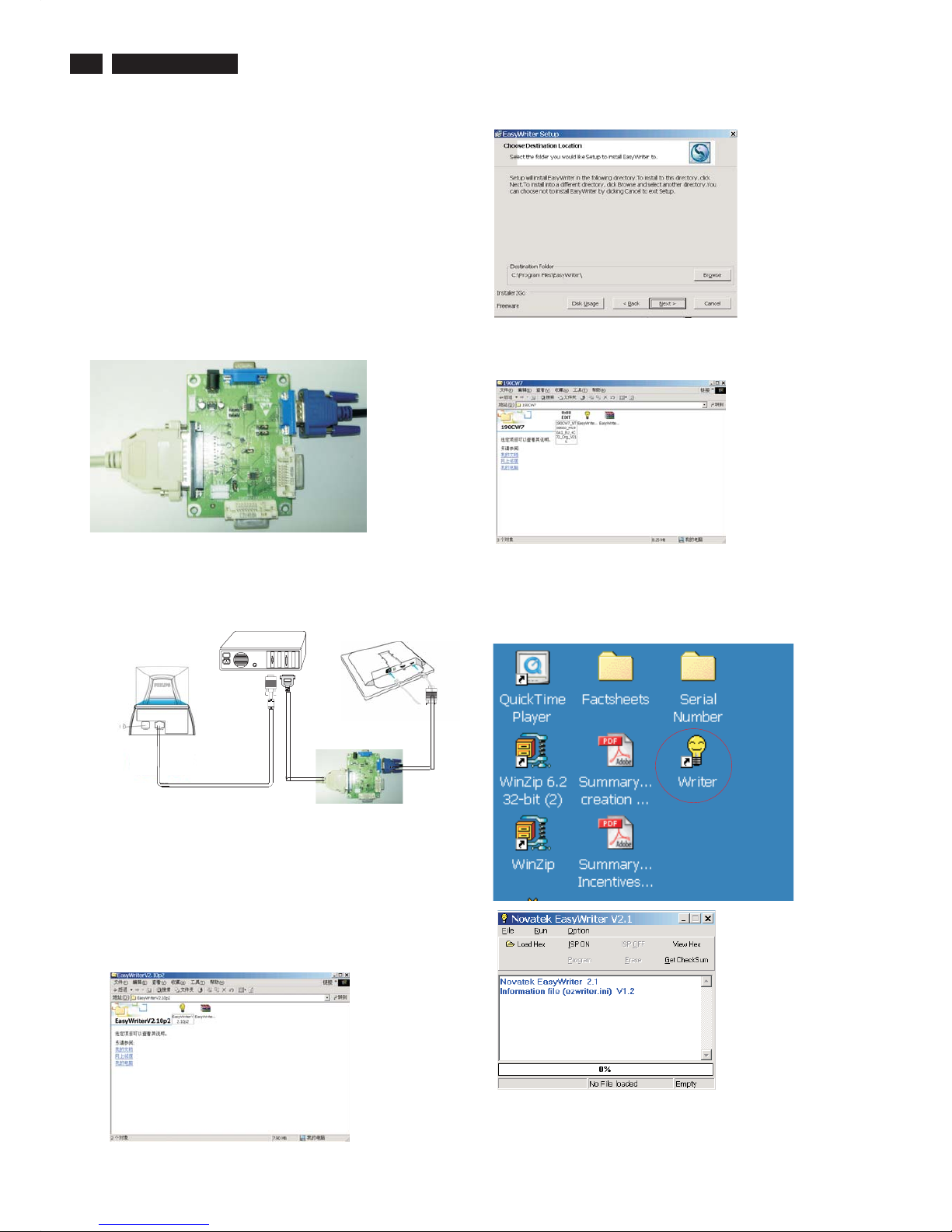
1. Double click the Easywriter.exe icon in desktop then appears
window as shown in Fig.7 .
Step 5 :Copy the 190CW7_NT68663_M190A1_EU_4C70_Org_V015
to C:\190CW7 as shown in Fig. 5 .
6. Install and setup the Easywriter program
Step 1 : Make a folder in your PC as shown in Fig. 3.
For example : C:\190CW7
Step 2 : Copy ISP Software Easywriter into your folder
as shown in Fig.3.
Step 3 : Unzip Easywriter.zip into your folder as shown in Fig. 3.
Step 4 : Double click the EasyWriterV2.10p2 icon to install the
Application as Fig. 4.
.zip
Configuration and procedure
"Easywriter " The software is provided by Novatek to upgrade the
firmware of CPU.
DDC2BI_ISP TOOL (3138 149 53161) is for the interface between
"Parallel Port of PC" and "15 pin-D-SUB connector of Monitor".
It is a windows-based program, which cannot be run in MS-DOS.
System and equipment requirements
1. An i486 (or above) personal computer or compatible.
2. Microsoft operation system Windows 95/98/2000/XP.
4. as shown in Fig. 1
3. ISP Software " Easywrite "
DDC2BI_ISP TOOL (3138 106 10396)
5. Connect and Mains cord to Monitor as shown
in Fig. 2.
DDC2BI_ISP TOOL
Fig. 1
Fig. 4
Fig. 5
Fig. 6
Fig. 7
Parallel Port to Print Port in PC
D-SUB to monitor
Fig.2
PC
To printer port (LTP1)
To video card
Video cable
Connect to
Mains cord
Monitor (A)
190CW7-Monitor (B)
D-Sub
Connect to Mains
cord at this moment.
------------------------------->
ISP box
Fig. 3
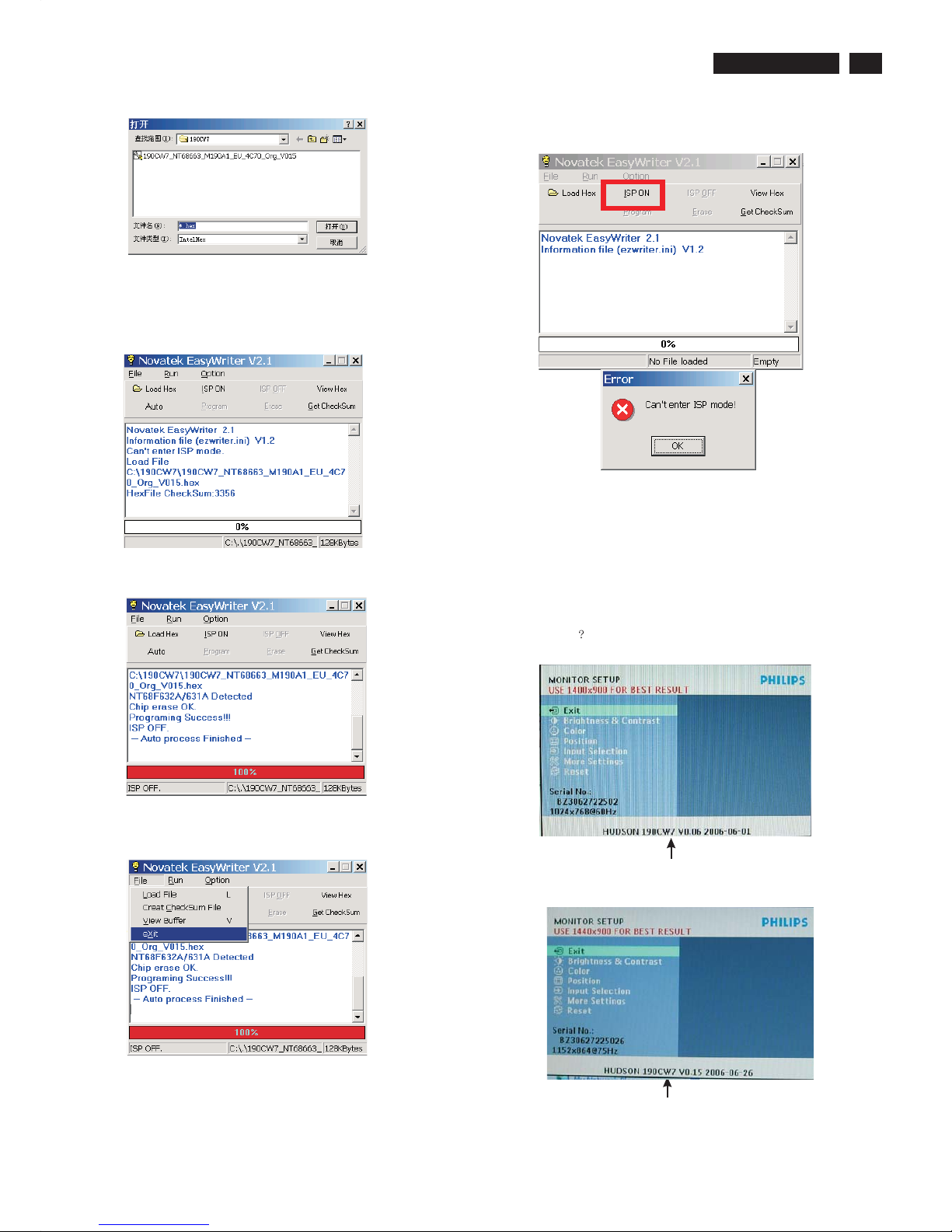
2. Press the Load hex then select the hex as shown in Fig. 8.
Firmware Upgrade for CPU
27
190CW7 LCD
Firmware Upgrade for CPU
Fig. 8
If there is a warring message coming as shown in Fig 12. , you
have to check the AC power, Video cable, or Novatek MCU.
Fig. 10
Fig. 11
Fig. 13
4 Press the file --> exit to end program , as shown in Fig. 11.
4) Turn off the monitor, exit the factory mode.
Fig. 14
5 Check the firmware version
1). Turn off monitor.
2).
3).Press "MENU" button, wait until the OSD menu come on the
Screen of the monitor.You will find, after upgrade, the version
have already changed from The former"HUDSON 190CW7
V0.06 2006-06-01" to the Present "HUDSON 190CW7 V0.15
2006-06-26 as shown in Fig. 13 and Fig. 14.
[Push "AUTO" & "MENU" buttons at the same time and hold them]
+[Press "power" button untill comes out "Windows screen" ]
=> then release all buttons.
3 Press the AUTO to running program , the firmware be updated
as shown in Fig. 9~10.
Fig. 12
Fig. 9
Factory Mode indicator
Factory Mode indicator
 Loading...