

Philips 170C7FS/27, 190C7FS/00, 170C7FS/78, 170C7FS/93, 190C7FS/27 Service Manual
...
Description Page
Important Safety Notice---- ------------------------------ 2
Technical Data-------------------------------------------3~4
Instalation/On Screen Display------------------------5~7
------------------------------------8
--------------------------------9
Troubleshooting ------------------------------------------10
Warning Message ----------------------------------------11
Lock/unlock,Aging,Factory mode ---------------------12
Mechanical Instructions----------------------------13~14
Color adjustment -----------------------------------------15
---------------------------------------------16
DDC Instructions& ---17~23
DDC DATA --------------------------------------------24~27
------------------------28~29
Failure Mode Of Panel
Smart Manage
Serial Number Definition
Philips Pixel Defect Policy
Firmware Upgrade for CPU
Horizontal frequencies
30-82kHz
Service
Service
Service
TABLE OF CONTENTS
Published by BCU Monitors Printed in Suzhou Copyright reserved Subject to modification K Aug. 4 2006
Description Page
------------30~31
Safety Test Requirments-------------------------------32
Wiring Diagram------------------------------------------33
Block Diagram---------------------------------------34~35
Scaler Diagram&C.B.A ----------------------------36~42
Power Diagram & C.B.A---------------------------43~46
Control Diagram&C.B.A---------------------------47~48
General product specification--------------------49~67
Exploded View --------------------------------------68~69
Repair tips--------------------------------------------70~71
Repair Flow chart-----------------------------------72~74
Spare&Recommended parts list-----------------75~78
Different parts list----------------------------------------82
----------------------------------------------83
FAQs (Frequently Asked Questions)
Revision List
REFER TO BACK COVER FOR IMPORTANT SAFETY GUIDELINES
CAUTION: USE A SEPARATE ISOLATION TRANSFORMER FOR THIS UNIT WHEN SERVICING.
ANY PERSON ATTEMPTING TO SERVICE THIS CHASSIS MUST FAMILIARIZE HIMSELF WITH THE CHASSIS
AND BE AWARE OF THE NECESSARY SAFETY PRECAUTIONS TO BE USED WHEN SERVICING ELECTRONIC
EQUIPMENT CONTAINING HIGH VOLTAGES.
SAFETY NOTICE
Chassis: HUDSON 7
GB
3138 106 10546
LCD Colour Monitor
170C7FS/00
170C7FS/27
170C7FS/69
170C7FS/75
170C7FS/78
170C7FS/93
190C7FS/00
190C7FS/27
190C7FS/69
190C7FS/75
190C7FS/78
190C7FS/93
190C7FS/96
Important Safety Notice
2
170C7 LCD
Go to cover page
Proper service and repair is important to the safe,
reliable operation of all Philips Consumer Electronics
Company** Equipment. The service procedures
recommended by Philips and described in this service
manual are effective methods of performing service
operations. Some of these service operations require
the use of tools specially designed for the purpose. The
special tools should be used when and as
recommended.
It is important to note that this manual contains various
CAUTIONS and NOTICES which should be carefully
read in order to minimize the risk of personal injury to
service personnel. The possibility exists that improper
service methods may damage the equipment. It is also
important to understand that these CAUTIONS and
NOTICES ARE NOT EXHAUSTIVE. Philips could not
possibly know, evaluate and advise the service trade of
all conceivable ways in which service might be done or
of the possible hazardous consequences of each way.
Consequently, Philips has not undertaken any such
broad evaluation. Accordingly, a servicer who uses a
service procedure or tool which is not recommended by
Philips must first satisfy himself thoroughly that neither
his safety nor the safe operation of the equipment will
be jeopardized by the service method selected.
* * Hereafter throughout this manual, Philips Consumer
Electronics Company will be referred to as Philips.
WARNING
Critical components having special safety
characteristics are identified with a by the Ref. No.
in the parts list and enclosed within a broken line*
(where several critical components are grouped in one
area) along with the safety symbol on the
schematics or exploded views.
Use of substitute replacement parts which do not have
the same specified safety characteristics may create
shock, fire, or other hazards.
Under no circumstances should the original design be
modified or altered without written permission from
Philips. Philips assumes no liability, express or implied,
arising out of any unauthorized modification of design.
Servicer assumes all liability.
* Broken Line
!
!
Take care during handling the LCD module with backlight
unit
- Must mount the moduleusing mounting holes arranged infour
corners.
- Do not press onthe panel, edge of theframe strongly or electric
shock as this will result in damage to the screen.
- Do not scratch orpress on the panel withany sharp objects, such
as pencil or pen asthis may result in damage to the panel.
- Protect the module fromthe ESD as it maydamage the electronic
circuit (C-MOS).
- Make certain that treatment person s body are grounded through
wrist band.
- Do not leave themodule in high temperature andin areas of high
humidity for a long time.
- Avoid contact with water as it may ashort circuit within the module.
- If the surface ofpanel become dirty, please wipe it off with a soft
material. (Cleaning with a dirty or rough cloth may damage the
panel.)
3
Technical Data - 170C7
Go to cover page
170C7 LCD
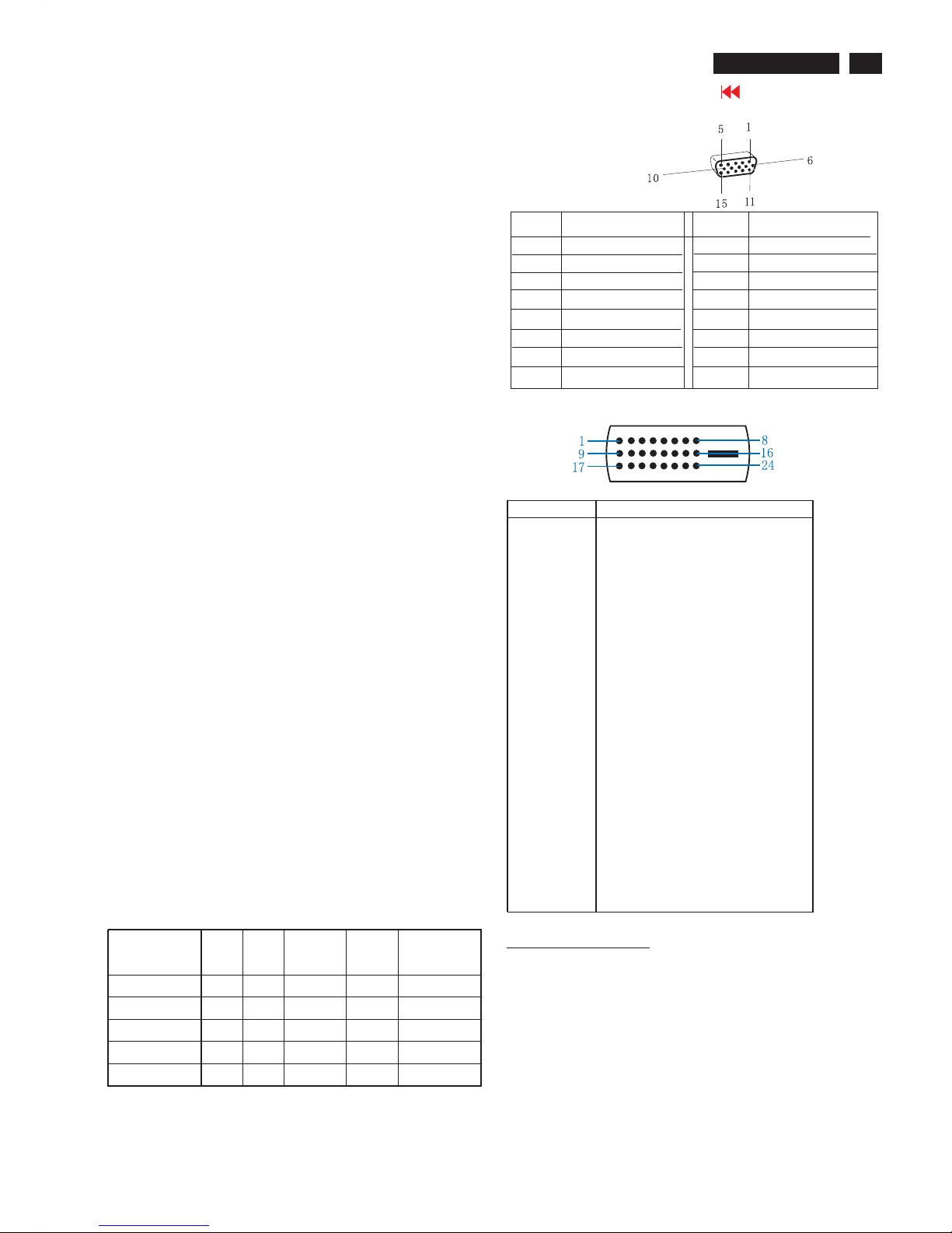
Pin Assignment
Input DVI-D connector pin
Red video input
Green video input
Blue video input
GND
Cable detect
Red video GND
Green video GND
Blue video GND
DDC +3.3V OR +5V
GND
GND
Serial data line (SDA)
H-sync
V-sync
Data clock line (SCL)
7
8
6
5
4
3
2
1
9
10
11
12
13
14
15
Pin No.
Pin No.
Assignment
Assignment
Pin No. Description
1
T.M.D.S. data2-
2
T.M.D.S. data2+
3
T.M.D.S. data2 shield
4
No Connect
5
No Connect
6
DDC clock
7
DDC data
8
No Connect
9
T.M.D.S. data1-
10
T.M.D.S. data1+
11
T.M.D.S. data1 shield
12
No Connect
13
No Connect
14
+5V Power
15
Ground (for +5V) - Cable detect
16
Hot plug detect
17
T.M.D.S. data0-
18
T.M.D.S. data0+
19
T.M.D.S. data0 shield
20
No Connect
21
No Connect
22
T.M.D.S clock shield
23
T.M.D.S. clock+
24
T.M.D.S. clock-
LCD
Type NR. : LM170E03 TLB1
Number of Pixels. : 1280 (H) x1024 (V)
Physical Size. : 358.5(w)*296.5(h)*17(d) mm
Pixel Pitch. : 0.264 mm x 0.264 mm
Color pixel arrangement. : RGB stripes arrangement
Support Color. : 16.2M colors
Display Mode. : Normally White
Backlight. : CCFL edge light system
Active area. (WXH). : 337.92 x 270.336mm (17" diagonal)
Viewing Angle (CR>=10). : Right:80 , Left:80 , UP:75 , down:85
Contrast ratio. : 800 :1(typic
White luminance. : 300 nit
Type NR. : CLAA170EA07 P
Number of Pixels. : 1280 (H) x1024 (V)
Physical Size. : 358.5(w)*296.5(h)*17.5(d) mm
Pixel Pitch. : 0.264 mm x 0.264 mm
Color pixel arrangement . : RGB vertical stripes
Support Color. : 16.2M colors
Display Mode. : Normally White
Backlight. : CCFL edge light system
Active area. (WXH). : 337.9 x 270.3 mm (17" diagonal)
Viewing Angle (CR>=10). : Right:80 , Left:80 , UP:80 , down:80
Contrast ratio. : 700 :1(typic)
White luminance. : 300 nit
Type NR. : M170E5-L0C
Number of Pixels. : 1280 (H) x1024 (V)
Physical Size. : 358.5(w)*296.5(h)*17.0(d) mm
Pixel Pitch. : 0.264 mm x 0.264 mm
Color pixel arrangement. : RGB vertical stripes
Support Color. : 16.7M colors
Display Mode. : Normally White
Backlight. : CCFL edge light system
Active area. (WXH). : 337.92 x 270.34 mm (17" diagonal)
Viewing Angle (CR>=10). : Right :80; Left :80 ; Up : 80 ; Down: 80
White luminance. : 300 nit
Video dot rate. : < 140 MHz
Power input. : 90-264 V AC, 50/60 ± 2Hz
Power consumption. : < 36 W maximum
Operating < 31W (typical),
Standby < 1W.
DC power switch off < 1W.
Power cord length : 1.8M
Power cord type : 3 lead with earth plug
Power indicator : LED (ON: green, Standby: amber)
Auto power saving : EPA, Nutek, VESA, DPMS,
Dimensions. : 403 x 392 x 171 mm (incl. Pedestal)
Weight. : 4.6 kg
Scanning frequencies
H-Frequency. : 30K - 82 KHz
V-Frequency. : 56 - 76 Hz
Power Management Definition
STATUS
H-
syncV-sync
Video Power LED
On On On Active <36W Green
Stand-by Off On Blanked <1W
Amber LCD
Suspend On Off Blanked <1W
Amber LCD
Off Off Off Blanked <1W Amber LCD
DCPoweroff N/A <1W LCDOff
Environmental conditions
Operating
- Temperature : 0 to 35 degree C
- Humidity : 80% max
- Altitude : 0-3658m
- Air pressure : 600-1100 mBAR
Storage
- Temperature : -20 to 60 degree C
- Humidity : 85% max ( < 40 degree C )
- Altitude : 0-12192m
- Air pressure : 300-1100 mBAR
Note: recommend at 5 to 35°C, Humidity less than 60 %
4
Go to cover page
170C7 LCD
Technical Data - 190C7
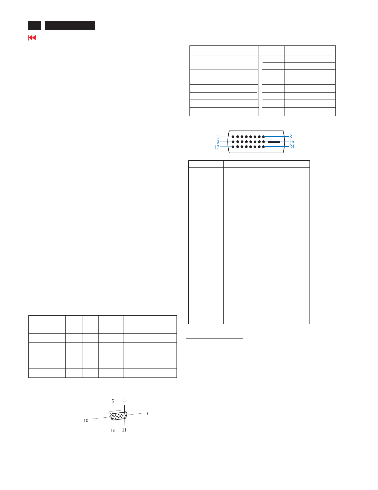
Pin Assignment
Input DVI-D connector pin
Red video input
Green video input
Blue video input
GND
Cable detect
Red video GND
Green video GND
Blue video GND
DDC +3.3V OR +5V
GND
GND
Serial data line (SDA)
H-sync
V-sync
Data clock line (SCL)
7
8
6
5
4
3
2
1
9
10
11
12
13
14
15
Pin No.
Pin No.
Assignment
Assignment
Pin No. Description
1
T.M.D.S. data2-
2
T.M.D.S. data2+
3
T.M.D.S. data2 shield
4
No Connect
5
No Connect
6
DDC clock
7
DDC data
8
No Connect
9
T.M.D.S. data1-
10
T.M.D.S. data1+
11
T.M.D.S. data1 shield
12
No Connect
13
No Connect
14
+5V Power
15
Ground (for +5V) - Cable detect
16
Hot plug detect
17
T.M.D.S. data0-
18
T.M.D.S. data0+
19
T.M.D.S. data0 shield
20
No Connect
21
No Connect
22
T.M.D.S clock shield
23
T.M.D.S. clock+
24
T.M.D.S. clock-
LCD
Type NR. : LM190E08 TLB1
Number of Pixels. : 1280 (H) x1024 (V)
Physical Size. : 396.0(w)*324.0(h)*16.5(d) mm
Pixel Pitch. : 0.294 mm x 0.294 mm
Color pixel arrangement. : RGB stripes arrangement
Support Color. : 16.7M colors
Display Mode. : Normally White
Backlight. : CCFL edge light system
Active area. (WXH). : 376.32 x 301.056mm (19" diagonal)
Viewing Angle (CR>=10). : Right:80 , Left:80 , UP:75 , down:85
Contrast ratio. : 800 :1(typic
White luminance. : 300 nit
Type NR. : CMO M190E5 L0E
Number of Pixels. : 1280 (H) x1024 (V)
Physical Size. : 396.0(w)*324.0(h)*16.5(d) (Typ) mm
Pixel Pitch. : 0.294 mm x 0.294 mm
Color pixel arrangement. : RGB vertical stripes
Support Color. : 16.2M colors
Display Mode. : Normally White
Backlight. : CCFL edge light system
Active area. (WXH). : 376.32x301.056mm (19" diagonal)
Viewing Angle (CR>=10). : Right:85 , Left:85 , UP:80 , down:80
Contrast ratio. : 700 :1(typic)
White luminance. : 300 nits
Dimension (WxHxD) * : 442 x 420 x 201 mm (incl. Pedestal)
Weight : 5.3 kg
Tilt : -5 ~ 25°C
Main Voltage : AC 90 - 135 Vrms and 170 - 264 Vrms,
50/60±2Hz
Power consumption: 40W Max.
Operating < 36W (typical), Standby < 2W.
DC power switch off < 1W.
Power cord length : 1.8M
Power cord type: 3 lead with earth plug
Power indicator: LED (ON: green,
Standby: amber)
Auto power saving : EPA, Nutek, VESA, DPMS,
Scanning frequencies
Horizontal scan : 30 - 82 KHz
Vertical scan : 56 - 76 Hz
Power Management Definition
STATUS
H-
syncV-sync
Video Power LED
On On On Active <40W Green
Stand-by Off On Blanked <1W
Amber LCD
Suspend On Off Blanked <1W
Amber LCD
Off Off Off Blanked <1W Amber LCD
DCPoweroff N/A <1W LCDOff
Environmental conditions
Operating
- Temperature : 0 to 40 degree C
- Humidity : 80% max
- Altitude : 0-3658m
- Air pressure : 600-1100 mBAR
Storage
- Temperature : -20 to 60 degree C
- Humidity : 95% max
- Altitude : 0-12192m
- Air pressure : 300-1100 mBAR
Note: recommended at 5 to 35°C, humidity less than 60%.
5
Go to cover page
170C7 LCD
Installation
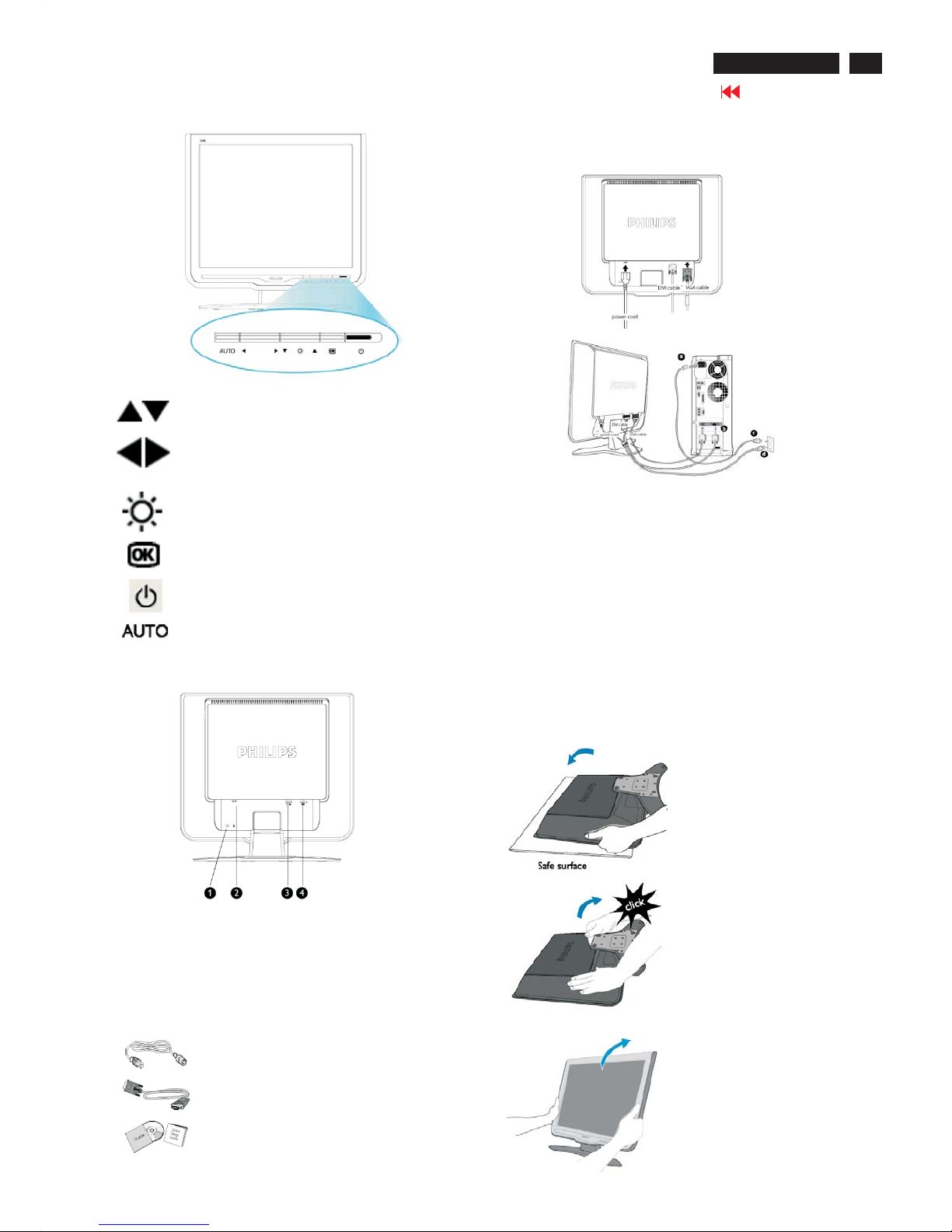
Front View
UP and DOWN buttons are used when adjusting
the OSD of your monitor.
LEFT and RIGHTbuttons, like the UPand DOWN
buttons, are also used in adjusting the OSD of
your monitor.
BRIGHTNESS hotkey. When the UP and DOWN
arrow buttons are pressed, the adjustment controls
for the BRIGHTNESS will show up.
OK button which when pressed will take you to
the OSD controls.
POWER button switches your monitor on.
Automatically adjust the horizontal position,
vertical position, phase and clock setting.
Rear View
1 Kensington anti-thief lock
2 AC power input
3 DVI-I input
4 VGAinput
Power cord
VGA signal cable
EDFU pack
Accessory Pack
Item Description
Connecting to Your PC
Connect the power cord and DVI cable to the back of the monitor
firmly. (Philips has preconnected VGAcable for the first installation.)
Connect the cables to the back of your computer by
following these steps:
(a) Turn off your computer and unplug its power cable.
(b) Connect the monitor signal cable to the video connector on the
back of your computer.
(c) Plug the power cord of your computer and your monitor into a
nearby outlet.
(d) Turn on your computer and monitor. If the monitor displays an
image, installation is complete.
The Base
Unfold and Fold the Base
Unfold the Base
Fold the Base
1) Push down the head of
monitor.
2) Pull up the base.
1) Put monitor face down
on the safe surface.
6
Go to cover page
170C7 LCD
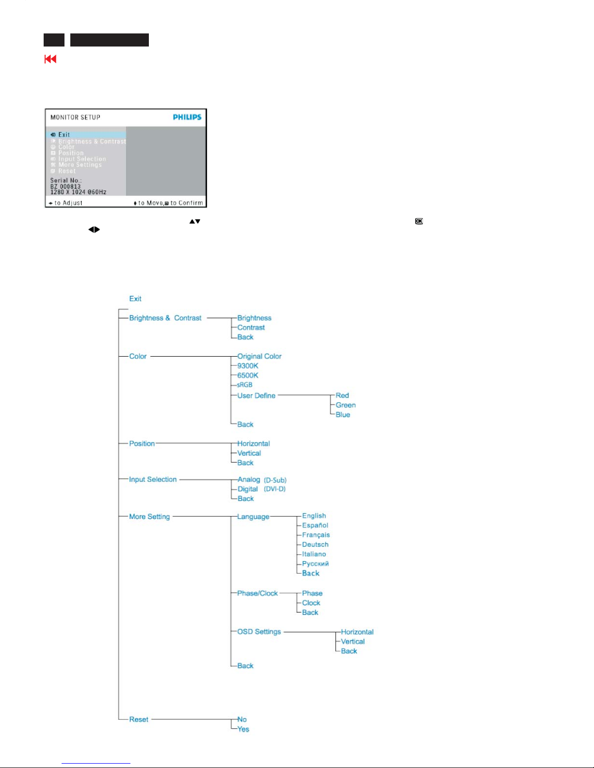
Description of the On Screen Display
On-Screen Display (OSD) is a feature in all Philips LCD monitors. It allows an end user to adjust screen performance or select functions
of the monitors directly through an on-screen instruction window. A user friendly on screen display interface is shown as below :
Basic and simple instruction on the control keys.
In the OSD shown above users can press buttons at the front bezel of the monitor to move the cursor, to confirm the choice or
change, and to adjust/select the change.
The OSD Tree
Below is an overall view of the structure of the On-Screen Display. You can use this as a reference when you want to work your way around the
different adjustments later on.
Main Menu Sub Menu
On Screen Display
Only available for Europe Model

7
Go to cover page
170C7 LCD
On Screen Display
Main Menu Sub Menu
Only available for Nafta Model
Main Menu Sub Menu
Only available for Asia Pacific Model
8
Go to cover page
170C7 LCD
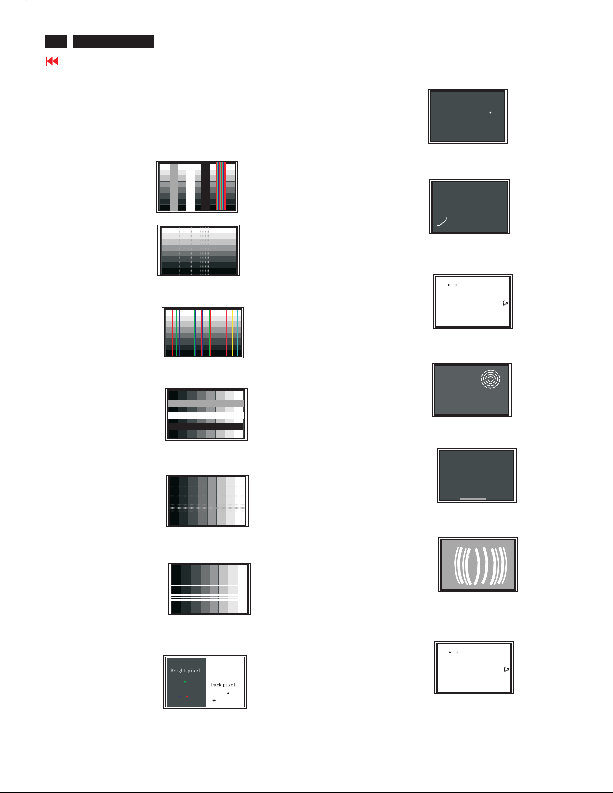
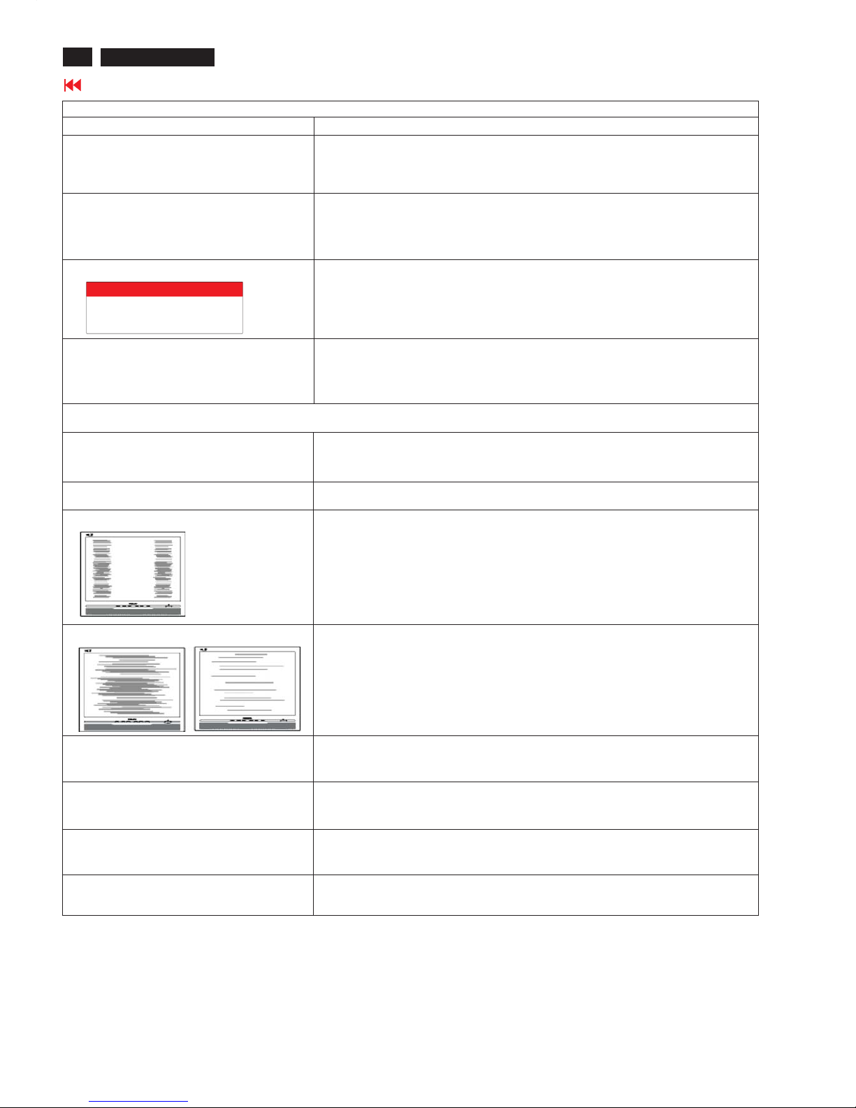
Failure description
Phenomenon
Vertical block defect
Vertical dim lines
Vertical lines defect
(Always bright or dark)
Horizontal block defect
Horizontal dim lines
Horizontal lines defect
(Always bright or dark)
Has bright or dark pixel
Polarizer has bubbles
Polarizer has bubbles
Foreign material inside
polarizer. It shows liner or
dot shape.
Concentric circle formed
Bottom back light of LCD is
brighter than normal
Back light un-uniformity
Backlight has foreign material.
Black or white color, liner or
circular type
Quick reference for failure mode of LCD panel
this page presents problems that could be made by LCD panel.
It is not necessary to repair circuit board. Simply follow the mechanical
instruction on this manual to eliminate failure by replace LCD panel.
Failure Mode Of Panel
9
Go to cover page
170C7 LCD
Philips' Flat Panel Monitors Pixel Defect Policy
Philips strives to deliver the highest quality products. We
use some of the industry's most advanced manufacturing
processes and practice stringent quality control. However,
pixel or sub pixel defects on the TFT LCD panels used in
flat panel monitors are sometimes unavoidable. No
manufacturer can guarantee that all panels will be free
from pixel defects, but Philips guarantees that any monitor
with an unacceptable number of defects will be repaired or
replaced under warranty. This notice explains the different
types of pixel defects and defines acceptable defect levels
for each type. In order to qualify for repair or replacement
under warranty, the number of pixel defects on a TFT LCD
panel must exceed these acceptable levels. For example,
no more than 0.0004% of the sub pixels on a 15" XGA
monitor may be defective. Furthermore, Philips sets even
higher quality standards for certain types or combinations
of pixel defects that are more noticeable than others. This
policy is valid worldwide.
Pixels and Sub pixels
A pixel, or picture element, is composed of three sub pixels
in the primary colors of red, green and blue. Many pixels
together form an image. When all sub pixels of a pixel are lit,
the three colored sub pixels together appear as a single
white pixel. When all are dark, the three colored sub pixels
together appear as a single black pixel. Other combinations
of lit and dark sub pixels appear as single pixels of other
colors.
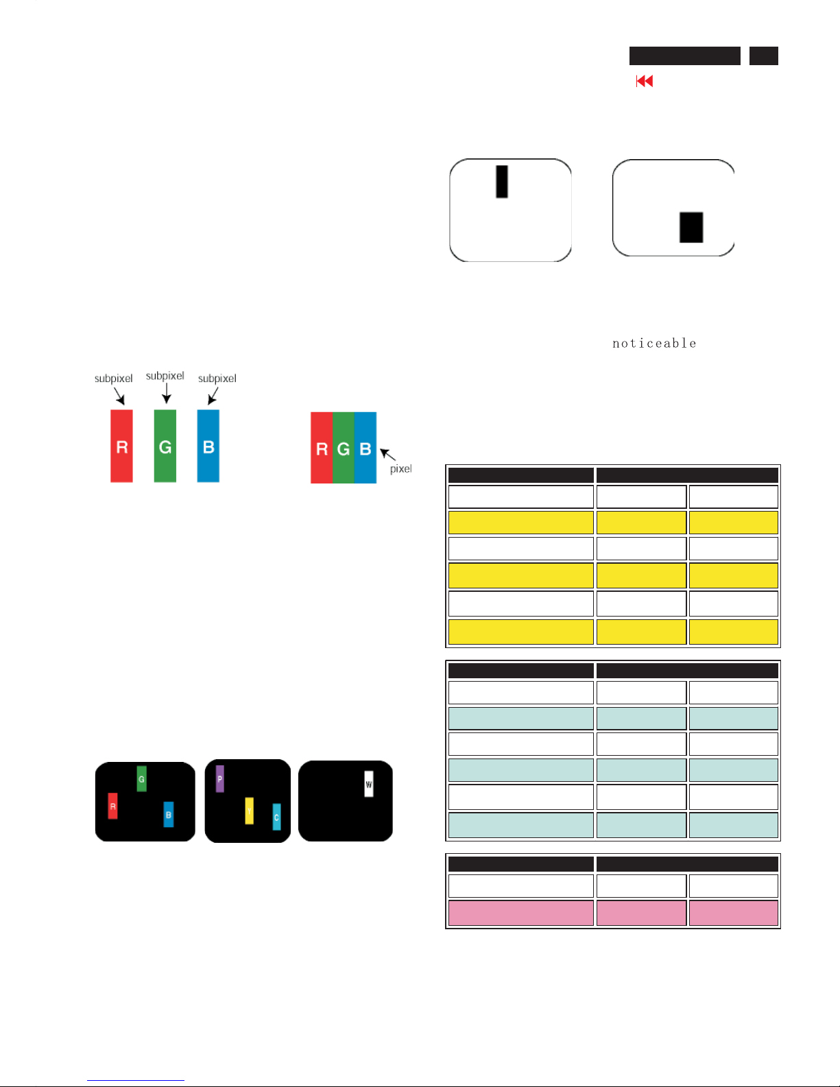
Types of Pixel Defects
Pixel and sub pixel defects appear on the screen in different
ways. There are two categories of pixel defects and several
types of sub pixel defects within each category. Bright dot
defects appear as pixels or sub pixels that are always lit or
'on'. These are the types of bright dot defects:
One lit red,
green or
blue sub pixel
Two adjacent lit
sub pixels:
- Red+ Blue =Purple
- Red+ Green =Yellow
- Green+ Blue =Cyan
(Light Blue)
Three adjacent lit
sub pixels
(one white pixel)
Black Dot Defects Black dot defects appear as pixels or sub
pixels that are always dark or 'off'. These are the types of black
dot defects:
One dark sub pixel Two or three adjacent dark sub pixels
Proximity of Pixel Defects
Because pixel and sub pixels defects of the same type that are
near to one another may be more , Philips also
specifies tolerances for the proximity of pixel defects.
Pixel Defect Tolerances
In order to qualify for repair or replacement due to pixel defects
during the warranty period, a TFT LCD panel in a Philips flat panel
monitor must have pixel or sub pixel defects exceeding the
tolerances listed in the following tables.
Note:
* 1 or 2 adjacent sub pixel defects = 1 dot defect
All Philips monitors are ISO13406-2 Compliant
BRIGHT DOT DEFECTS ACCEPTABLE LEVEL
MODEL 170C7 190C7
1 lit subpixel 3orfewer 3orfewer
2 adjacent lit subpixels 1 or fewer 1 or fewer
3 adjacent lit subpixels (one
white pixel)
0 0
Distance between two bright
dot defects*
15 mm or more 25 mm or more
Total bright dot defects of all
types
3orfewer 3orfewer
BLACK DOT DEFECTS ACCEPTABLE LEVEL
MODEL 170C7 190C7
1 dark subpixel 4orfewer 5orfewer
2 adjacent dark subpixels 2 or fewer 2 or fewer
3 adjacent dark subpixels 0 0
Distance between two black
dot defects*
15 mm or more 15 mm or more
Total black dot defects of all
types
4orfewer 5orfewer
BLACK DOT DEFECTS ACCEPTABLE LEVEL
MODEL 170C7 190C7
Total bright or black dot
defects of all types
5orfewer 5orfewer
Philips Pixel Defect Policy
10
Go to cover page
170C7 LCD
Common Problems
Having this problem
Check these items
No Picture
(Power LED not lit)
1.Make sure the power cord is plugged into the power outlet and into the back of the
monitor.
2.First, ensure that the power button on the front of the monitor is in the OFF position,
then press it to the ON position.
No Picture
(Power LED is amber or yellow)
1.Make sure the computer is turned on.
2. Make sure the signal cable is properly connected to your computer.
3.Check to see if the monitor cable has bent pins.
4.The Energy Saving feature may be activated
Screen says
1. Make sure the monitor cable is properly connected to your computer. (Also refer
to the Quick Set-Up Guide).
2.Check to see if the monitor cable has bent pins.
3. Make sure the computer is turned on.
AUTO button not working properly
1.The Auto Function is designed for use on standard Macintosh or IBM-compatible
PCs running Microsoft Windows.
2. It may not work properly if using nonstandard PC or video card.
Imaging Problems
Display position is incorrect
1.Press the Auto button.
2. Adjust the image position using the Horizontal Position and/or Vertical
Position in OSD Main Controls.
Image vibrates on the screen
Check that the signal cable is properly connected to the graphics board or PC.
Vertical flicker appears
1. Press the Auto button.
2.
Eliminate the vertical bars using the More Settings of Phase/
Clock in OSD Main Controls.
Horizontal flicker appears
1. Press the Auto button.
2.
Eliminate the vertical bars using the More Settings of Phase/
Clock in OSD Main Controls.
The screen is too bright or too dark
Adjust the contrast and brightness on OSD Main Controls. (The backlight of the
LCD monitor has a fixed life span. When the screen becomes dark or begins to
flicker, please contact your dealer).
An after-image appears
If an image remains on the screen for an extended period of time, it may be
imprinted in the screen and leave an afterimage. This usually disappears after a
few hours.
An after-image remains after the power
has been turned off.
This is characteristic of liquid crystal and is not caused by a malfunction or
deterioration of the liquid crystal. The after-image will disappear after a peroid
of time.
Green, red, blue, dark, and white dots
Remains
The remaining dots are normal characteristic of the liquid crystal used in
today's technology.
ATTENTION
NO VIDEO INPUT
Troubleshooting
11
Go to cover page
170C7 LCD
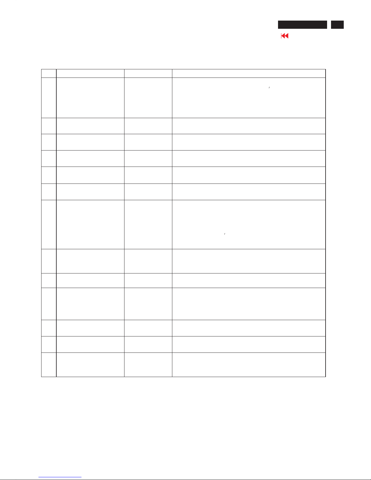
Warning Message
Item Attention Signals Display Time Condition
1 CANNOT DISPLAY THIS
VIDEO MODE, CHANGE
COMPUTER DISPLAY
INPUT TO 1280X1024 @
60HZ
30 mins This warning appears when the input signal from your computer is not in
a standard video mode or is out of the monitor
s scanning range. After
30 mins, monitor enters sleeping mode.
2 NO VIDEO INPUT 30 mins This message appears when there is no signal input but with cable while
AC or DC power on. After 30 mins, monitor enters sleeping mode.
3 CHECK CABLE
CONNECTION
30 mins This message appears when a signal cable is disconnected while
monitor is working. After 30 mins, monitor enters sleeping mode.
4 ENTERING SLEEP MODE 3 secs This message appears when monitor is about to enter power saving
mode.
5 WAITING FOR AUTOMATIC
ADJUSTMENT
till auto adjustment
finished
This message is displayed when the auto adjustment button is pressed.
It disappears when automatic adjustments are completed.
6 USE 1280X 1024 FOR BEST
RESULT
On top of OSD main
menu
The message will show up at the top of the OSD main menu in red color
when the input resolution is not the 1280x1024.
7 OSD MAIN CONTROLS
LOCKED
3 secs / or Till "OSD
MAIN CONTROLS
UNLOCKED"
appear
This message will appear 3 seconds to indicate the OSD MAIN
CONTROLS status when to lock or un-lock it by pressing "MENU(OK) "
button for more than 10 seconds while there is video input from PC. This
function provides the alternative that user can lock all the OSD main
control in case user don
t want the FOS performance setting to be
changed, for instance, during commercial exhibition.
8 OSD MAIN CONTROLS
UNLOCKED
3 secs This message will appear 3 seconds to indicate the OSD MAIN
CONTROLS status when to un-lock it by pressing "MENU (OK) " button
for more than 10 seconds while there is video input from PC.
9 the window of "VOLUME" 60 secs This message will appear when the VOLUME button is pressed.
10 THIS IS 85HZ OVERSCAN,
CHANGE COMPUTER
DISPLAY INPUT TO
1280X1024@60HZ
10 mins This message will appear 5 seconds in every 60 seconds for 10 minutes
when the input of PC video timing is at 85Hz mode.
Remark: AUTO is still functional in this mode
11 the window of OSD
"MONITOR SETUP "
60 secs This message will appear when the "OK" button is pressed.
12 the window of
"BRIGHTNESS"
60 secs This message will appear when the BRIGHTNESS button is pressed.
13 "SELECTED INPUT NOT
AVAILABLE"
3 secs This message will appear 3 seconds to indicate the SIGNAL SOURCE
status when change the signal source but it is not found while there is
video input from PC.
Warning message table
12
Go to cover page
170C7 LCD
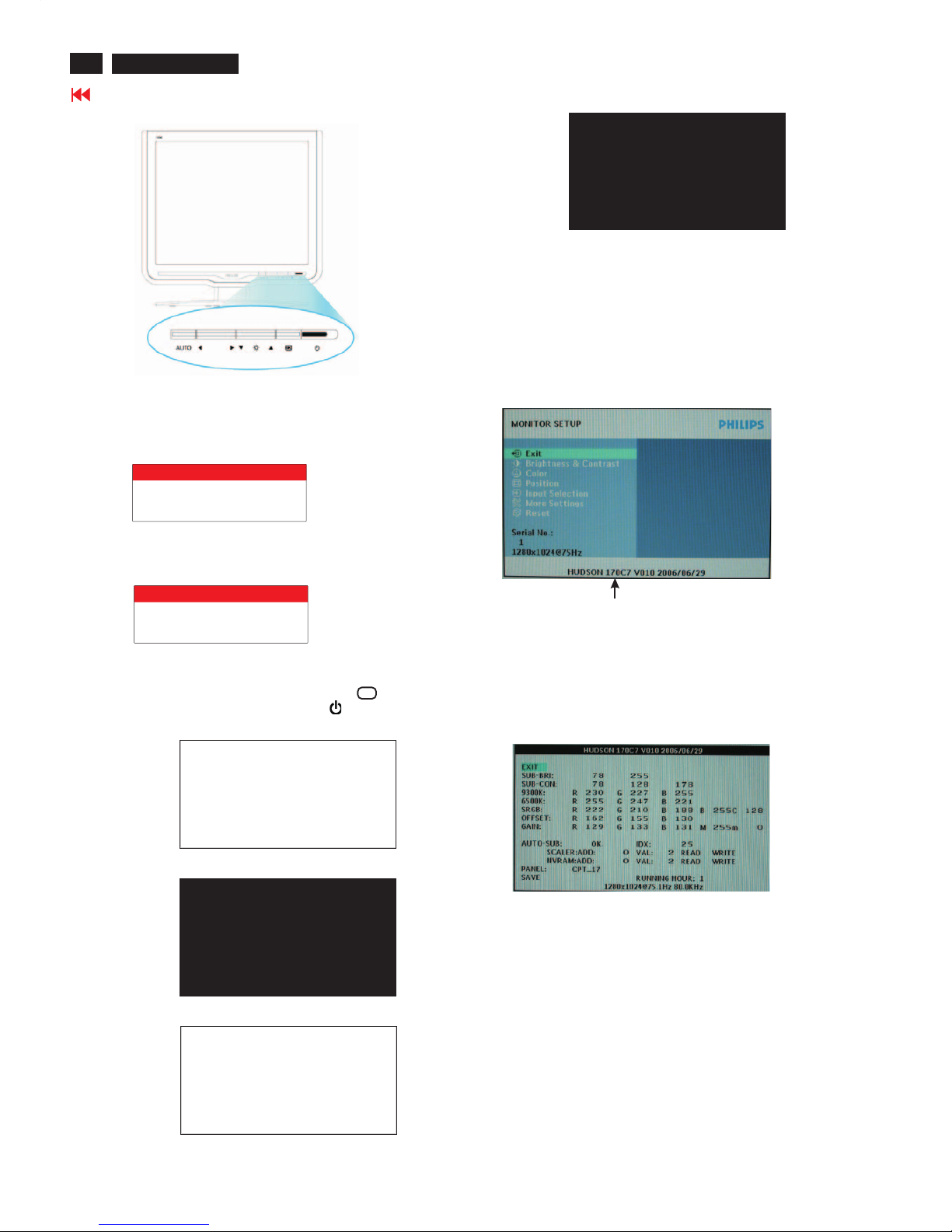
Lock/Unlock,Aging,Factory Mode
Front Control
To Lock/Unlock OSD FUNCTION(User Mode)
The OSD function can be locked by pressing"OK"button(1) for more
than 10 seconds, the screen shows following windows for 4 seconds.
Everytime when you press"OK" button, this message
appears on the screen automatically.
ATTENTION SIGNAL
OSD MAIN CONTROLS
LOCKED
Unlock OSD function
Unlocked OSD function can be released by pressing "OK" button for
more than 10 seconds again.
ATTENTION SIGNAL
OSD MAIN CONTROLS
UNLOCKED
After 15 seconds,
bring up:
----------
---------repeatly
Connect Signal cable again=> go back to normal display
After 15 seconds,
bring up:
After 30 seconds,
bring up:
AGING...
Access Aging Mode
Step1:D
Step 2 : [Push "AUTO"&"OK"buttons
at the same time and hold them]+[Press power " " button untill comes
out " AGING screen"] => then release all buttons.
Bring up:
isconnect Interface Cable between Monitor and PC.
Turn off LCD monitor.Then
AGING...
Access Factory Mode
1). Turn off monitor.
2).
3).Press "OK" button, wait until the OSD menu with Characters
"HUDSON 170C7 V010 2006/06/29" (below OSD menu) come
on the Screen of the monitor.
[Push "AUTO" & "OK" buttons at the same time and hold them]
+[Press "power" button untill comes out "Windows screen" ]
=> then release all buttons
Factory Mode indicator
Factory Menu
Cursor can move on gray color area
Hot key function: by pressing " UP " and " DOWN " key
Simultaneously at User Mode (or Factory Mode)
(PS: The OffsetRGBfunction can be used on reduce or eliminate
snowy noise on the background when the resolution of video signal
is 1280*1024 vertical 60Hz. Slightly increase or decrease the value
until snowy noise completely disappear.
SUB-BRI : Brightness value range(Min Max)
SUB-CON : Contrast value range(Min Mid Max)
SRGB-B : Brightness of sRGB
SRGB-C : Contrast of sRGB
Gain-m : Minimum value of User Gain
Gain-M : Maximum value of User Gain
AUTO-SUB : To do Auto color function when push Menu key
in white pattern
IDX : Limit current of inverter
SCALER : Read/Write scaler register
NVRAM : Read/Write eeprom address
Panel : HS, LG, AU, QDI, DEFAULT?.
EXIT : Exit Factory Menu
SAVE : Save the setup values of Factory Menu
13
Go to cover page
170C7 LCD
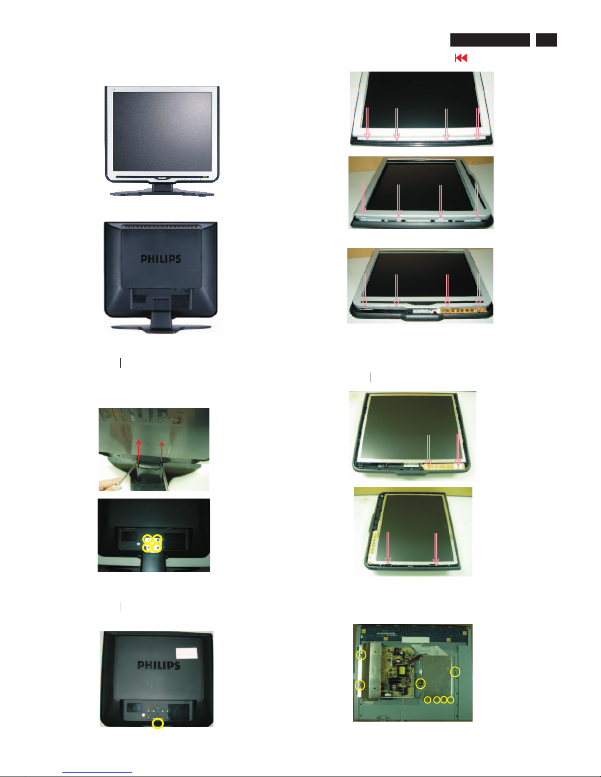
Mechanical Instruction
Front View
Back View
Step1. Remove the base
-Use two
-Remove the screws as shown in Fig.4, then remove the base
thin " " screw drivers to drive upon the cover simultaneously
as shown in Fig.3
Step2. Remove the Front Bezel
-Remove the one screw as shown in Fig.5
-Use the thin " " screw driver to open the clicks as shown
in Fig.6-8
Step4. Remove the Power and Scaler shielding.
- Remove the eight screws as shown in Fig.11
- Remove the as shown in Fig.12Power and Scaler shielding
Fig.1
Fig.2
Fig.4
Fig.5
Fig.6
Fig.9
Fig.10
Fig.11
Fig.3
Fig.8
Fig.7
Step3.Remove the Back cover
- Remove the two screws as shown in Fig.9 ,then remove the Control
board
-Use the thin " " type screw driver to open the clicks as shown in Fig.10
14
Go to cover page
170C7 LCD
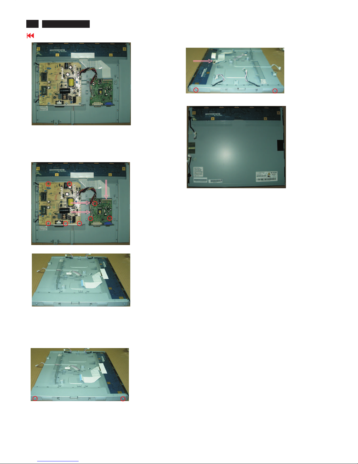
Mechanical Instruction
Step 5. Remove the sclar and power board.
- Remove the eight screws as shown in Fig.13
- Disconnect the three cables as shown in Fig.13
- Remove the scaler and power board as shown in Fig.14
***********************************************************************************************************************************
***********************************************************************************************************************************
In warranty, it is not allowed to disassembly the LCD panel, even the
backlight unit defect.
Out of warranty, the replacement of backlight units is a correct way
when the defect is caused by backlight (CCFL, Lamp).
Fig.12
Fig.13
Fig.14
Step6. Remove the Metal Frame.
- Remove the two screws as shown in Fig.15
- Remove the two screws as shown in Fig.16
- Disconnect the one cable as shown in Fig.16
Fig.15
Fig.16
Fig.17
15
Go to cover page
170C7 LCD
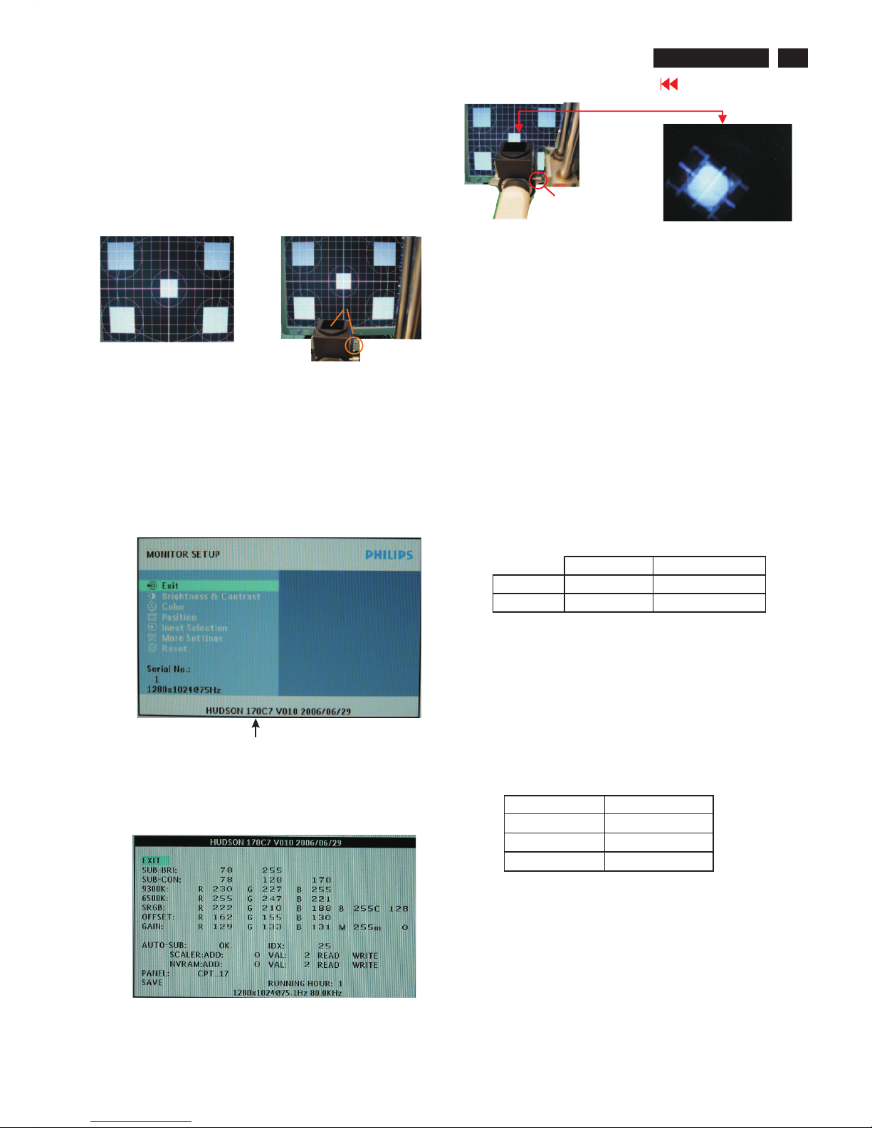
Color Adjustment
Alignment procedure
1. Turn on the LCD monitor.
2.Turn on the Timing/pattern generator. See Fig.1
3. Preset LCD color Analyzer CA-110
-Remove the lens protective cover of probe CA-A30.
-Set measuring/viewing selector to measuring position for reset
analyzer.(zero calibration) as Fig.2
- Turn on the color analyzer (CA-110)
-Press 0-CAL button to starting reset analyzer.
Fig. 1
Fig. 2
Clear imageClear image
Measurement/viewing selectorMeasurement/viewing selector
Fig. 3
4). Press button, then select factory mode indicator by"OK" "UP"
or "DOWN" button .Press"OK” button to bring up submenu
windows as below:
Fig.5
Cover (black)Cover (black)
Measurement viewing selectorMeasurement viewing selector
Fig. 4
Fig. 2
5.Display
Press "UP" or "DOWN" button to select . Change the value
by "LEFT" or "RIGHT" key until the X,Y co-ordinates as below
4. Access Factory Mode
1). Turn off monitor.
2).
3).Press "OK button, wait until the OSD menu with Characters"
HUDSON 170C7 V010 2006/06/29" (below OSD menu) come on
the Screen of the monitor. as shown in Fig3.
[Push "AUTO" & "OK" buttons at the same time and hold them]
+[Press "power" button untill comes out "Windows screen" ]
=> then release all buttons
"
Factory Mode indicator
6. Display Adjustment
6.1 Access to factory mode (RS232) in auto-alignment system. The
communication protocol switches to RS232.
6.2 Auto color adjustment (B)
Apply a 640*480/60Hz signal with 16 level grey test pattern, set
brightness control at 100%, and contrast control at 50%. Adjust
the R.G. B. offset, and gain to calibrate the color smoothly and
64-grey level distinguishable.
6.3 Adjustment of WHITE-D (B)
Apply a 1280*1024 / 60Hz signal with white pattern, set
brightness control at 100%, and contrast control at 50%. Adjust
the R, G, B Sub-Gain, for the screen center, the 1931 CIE
chromaticity (X, Y) co-ordinates shall be
Use Minolta CA-210 for color coordinates and luminance check.
Luminance is > 200 Nits in the center of the screen when
brightness at 100% and contrast set to 100%.
6.4 Adjustment of sRGB (B)
Apply a 1280*1024/ 60Hz signal with white pattern, set
brightness control at 100%, and contrast control at 50%.
Adjust the R, G, B Sub-Gain, for the screen center, the 1931
CIE chromaticity (X, Y) co-ordinates shall be;
sRGB
x(center) 0.313 ± 0.008
y(center) 0.329 ± 0.008
Ynits 180 ± 10
9300°K6500°K
x (center) 0.283 ± 0.020 0.313 ± 0.020
y (center) 0.297 ± 0.020 0.329 ± 0.020
16
Go to cover page
170C7 LCD
Smart Manage
Introduction
SmartManage Features and Benefits
Philips SmartControl
Philips SmartManage is an advanced solution for users, corporate/
institution IT administrator in particular, to manage their Philips
monitors as part of the asset management environment. The
solution includes three essential components, Philips SmartManage
Administrator, and Philips SmarControl and Agent. Philips
SmartManage is a solution joint developed by Philips and Altiris Inc.
The Philips SmartManage is a working console for IT management
to gather monitors assets information, run asset report, control
assets security, monitor assets security, and issue instant messages
to monitor users. Philips SmartManage includes the following major
features:
1. Provides an additional security measure that helps corporate
users safeguard their
investment.
2. Power saving feature that reduces utility costs and manpower
required to turn monitors on or off.
3. SmartControl provides an efficient means for adjusting monitor
performance and settings.
4. Built-in asset reports reduce audit/maintenance manpower, cycle
time and costs.
A trial version of SmartManage can be downloaded from
http://www.altiris.com/philips
For more information of Philips SmartManage, please contact with
Philips sales representatives in your country.
Notes: SmartManage is a software dedicated to business
environments. Personal users normally do not need to use
SmartManage.
The SmartControl and SmartManage Agent are deployed and
installed in computers using Philips monitors. With SmartControl
and SmartManage Agent, monitors and PCs can interact with the
administrator's inquiries. Because SmartControl operates on
individual PC, end users can also use SmartControl to adjust
monitor's performance settings.
1. Requirement
1. Graphic cards with nVIDIA (TNT2, GeForce, Quadro, or newer)
and ATI (Radeon or newer) graphic chipsets that support the
DDC/CI interface
2.Microsoft Windows 2000 and XP operation systems.
3. Philips monitors supporting DDC/CI interface
2. Installation
How to download "SmartControl Installation " file:
1. Visit http:// www.philips.com
2. Select "Your Country"
3. Click on "Support Center"
4. Click into "Monitors and PC Products"
5. Enter your model number
6. Enter "Software" page
7. Select "SmartControl Installation", and you can download
SmartControl and its driver for installation.
Please follow the guidance in the SmartControl installation program.
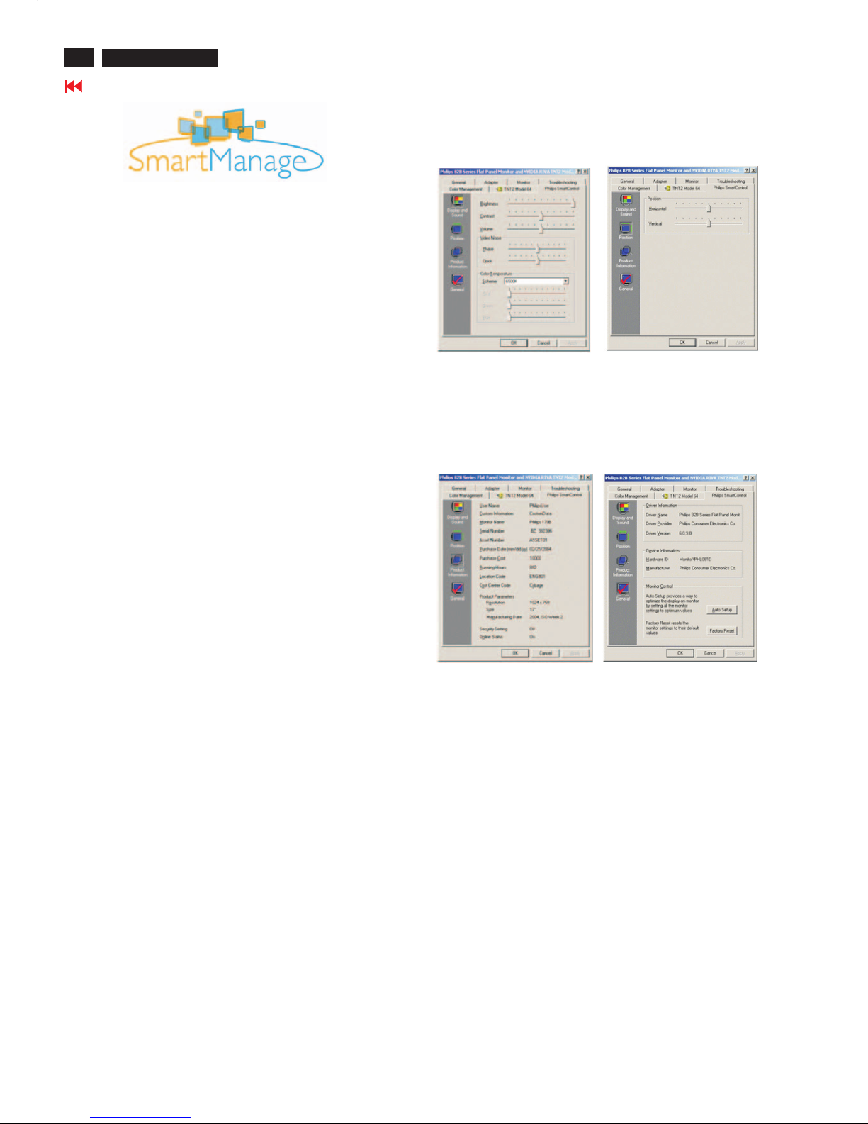
3. Accessing SmartControl
1. Right click on the desktop of your PC, and select Properties from
the shortcut menu pops up.
2. Click on Settings tab, and click on Advanced button.
3. Click Philips SmartControl tab.
4. SmartControl Options
1.Display and Sound
By moving the sliding bar toward left or right, users will be able
to adjust brightness, contrast, audio volume (if applicable),
video noise (not applicable when using DVI-D input), and color
temperatures.
2.Position
Users can adjust the horizontal and vertical position of the screen
by moving the sliding bar left and right. This function is disabled
when using DVI-D (digit) input.
3.Product Information
Click Product Information in the left pane to view the product
information stored in the monitor's memory.
4.General
Click on General for general information including driver
information, device information, and monitor control.
Within monitor control, users can click on Auto Setup to achieve
optimum performance or click on factory reset to reset the
parameters of the monitor. Such choices are disabled when using
DVI-D(digit) input.
17
Go to cover page
Pin No. Description
1 T.M.D.S. data2-
2 T.M.D.S. data2+
3 T.M.D.S. data2 shield
4 No Connect
5 No Connect
6 DDC clock
7 DDC data
8 No Connect
9 T.M.D.S. data1-
10 T.M.D.S. data1+
11 T.M.D.S. data1 shield
12 No Connect
13 No Connect
14 +5V Power
15 Ground (for +5V) - Cable detect
16 Hot plug detect
17 T.M.D.S. data0-
18 T.M.D.S. data0+
19 T.M.D.S. data0 shield
20 No Connect
21 No Connect
22 T.M.D.S clock shield
23 T.M.D.S. clock+
24 T.M.D.S. clock-
General
DDC Data Re-programming
In case the DDC data memory IC or main EEPROM which storage all
factory settings were replaced due to a defect, the serial numbers have
to be re-programmed "Analog DDC IC, Digital DDC IC & EEPROM".
It is advised to re-soldered DDC IC and main EEPROM from the old
board onto the new board if circuit board have been replaced, in this case
the DDC data does not need to be re-programmed.
Additional information
Additional information about DDC (Display Data Channel) may be
obtained from Video Electronics Standards Association (VESA).
Extended Display Identification Data(EDID) information may be also
obtained from VESA.
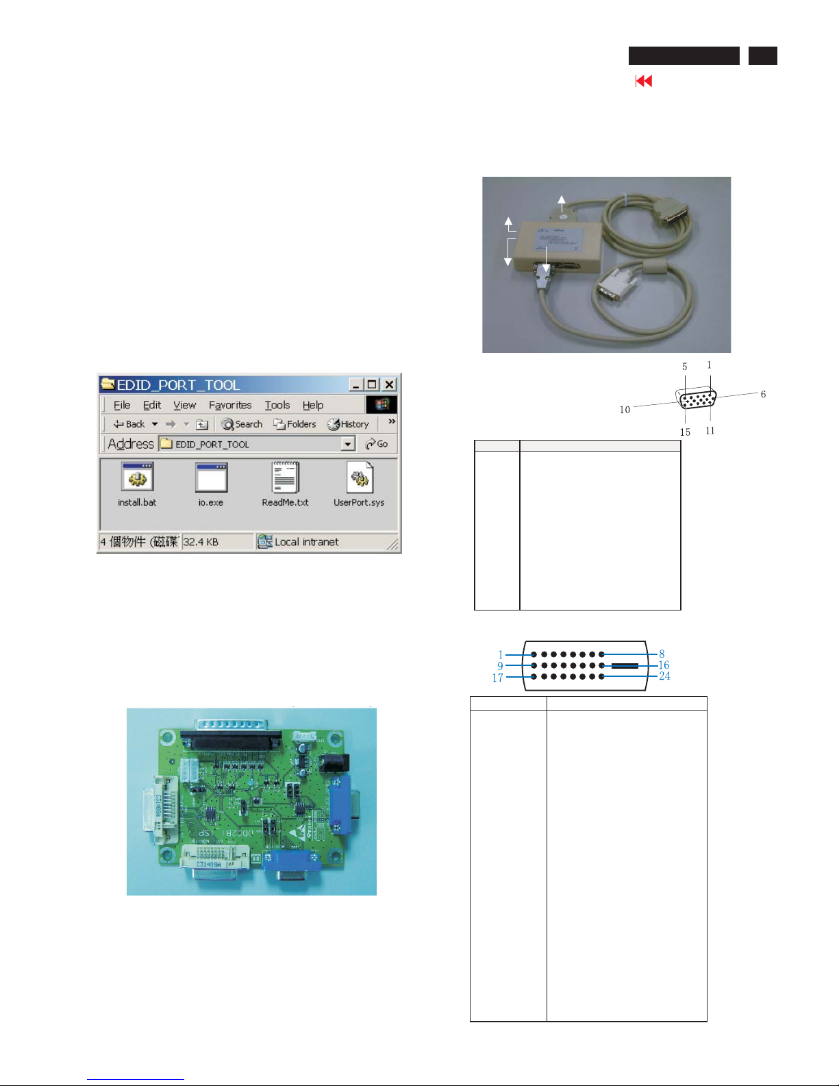
1. An i486 (or above) personal computer or compatible.
2. Microsoft operation system Windows 95/98 .
Y o Install the EDID_PORT_Tool under Win2000/XP . As
Fig. 1 .
A. Cody the "UserPort.sys" to C:\WINNT\system32\drivers(win2000)
C:\WINDOWS\system32\drivers(winXP)
B. Running " io.exe" everytime, Before you start to programming
edid data .
4. A/D Alignment kits (12NC: 3138 106 10396):
inclusion : a. Alignment box x1 (Fig. 2)
b. Printer cable x1
c. (D-Sub) to (D-Sub) cable x1
D. (D-Sub) to (DVI) cable x1
System and equipment requirements
ou have t
3. EDID46.EXE program
Fig. 1
Fig. 1
Fig. 2
To Monitor
D-sub/DVI cable
DC 8~12V
To Printer port
Power
indicator
Note: The alignment box has already build-in a batteries socket for
using batteries (8~12V) as power source. Pull out the socket by
remove four screws at the rear of box. Please do not forget that
remove batteries after programming. The energy of batteries can
only drive circuits for a short period of time.
PIN No. SIGNAL
1 Red video input
2 Green video input / sync on green
3 Blue video input
4GND
5 GND - Cable detect
6RedvideoGND
7 Green video GND
8 Blue video GND
9DDC+3.3Vor+5V
10 Logic GND
11 GND
12 Serial data line (SDA)
13 H-sync / H+V
14 V-sync
15 Data clock line (SCL)
Pin assignment
A. 15-pin D-Sub Connector
B. Input DVI -D Connector pin
Fig. 3
DDC Instructions
170C7 LCD
18
Go to cover page
Step 3: Installation of EDID46.EXE
Method 1: Start on DDC program
Start Microsoft Windows.
1. The Program"EDID46.EXE" in service manual cd-rom be copyed to C:\ .
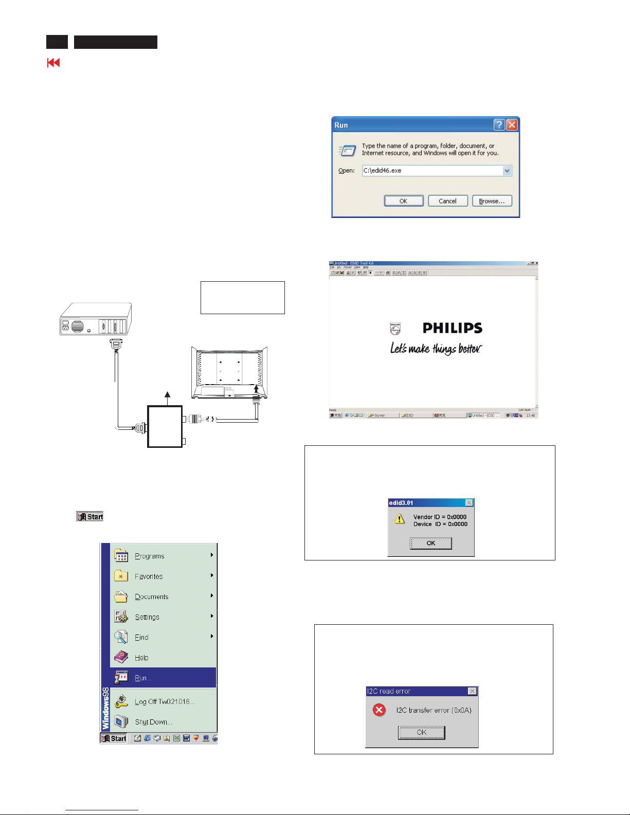
2. Click , choose Run at start menu of Windows as shown
In Fig. 5.
Fig. 5
4. Click OK button. The main menu appears (as shown in Fig. 7).
This is for initialize alignment box.
Fig. 7
Fig. 6
3. At the submenu, type the letter of your computer's hard disk drive
followed by :EDID46 (for example, C:\EDID46, as shown in Fig. 6).
Note 2: During the loading, EDID46 will verify the EDID data which just
loaded from monitor before proceed any further function, once
the data structure of EDID can not be recognized, the following
error message will appear on the screen as below. Please
confirm following steps to avoid this message.
1. The data structure of EDID was incorrect.
2. DDC IC that you are trying to load data is empty.
3. Wrong communication channel has set at configuration setup
windows.
4. Cables loosed or poor contact of connection.
1
Fig. 8
Note 1: If the connection is improper, you will see the following error
message (as shown in Fig. 8) before entering the main menu.
Meanwhile, the (read EDID) function will be disable. At this
time, please make sure all cables are connected correctly and
fixedly, and the procedure has been performed properly.
Fig. 9
Configuration and procedure
There is no Hardware DDC (DDC IC) anymore. Main EEPROM stores
all factory settings and DDC data (EDID code) which is also called
Software DDC. The following section describes the connection and
procedure for Software DDC application. The main EEPROM can be reprogrammed by enabling '' factory memory data write'' function on the
DDC program (EDID46.EXE).
Initialize alignment box
In order to avoid that monitor entering power saving mode due
to sync will cut off by alignment box, it is necessary to initialize
alignment box before running programming software
(EDID46.EXE). Following steps show you the procedures and
connection.
Step 1: Supply 8-12V DC power source to the Alignment box by
plugging a DC power cord .
Step 2: Connecting printer cable and D-Sub cable of monitor as Fig. 4
Fig. 4
PC
1= Power connector
2= D-SUB connector
To printer port (
L
TP1)
DC Power
8-12 V
Printer
Port
To
Monitor
To P C
1
2
----->
----->
DDC Instructions
170C7 LCD
19
Go to cover page
DDC Instructions
170C7 LCD
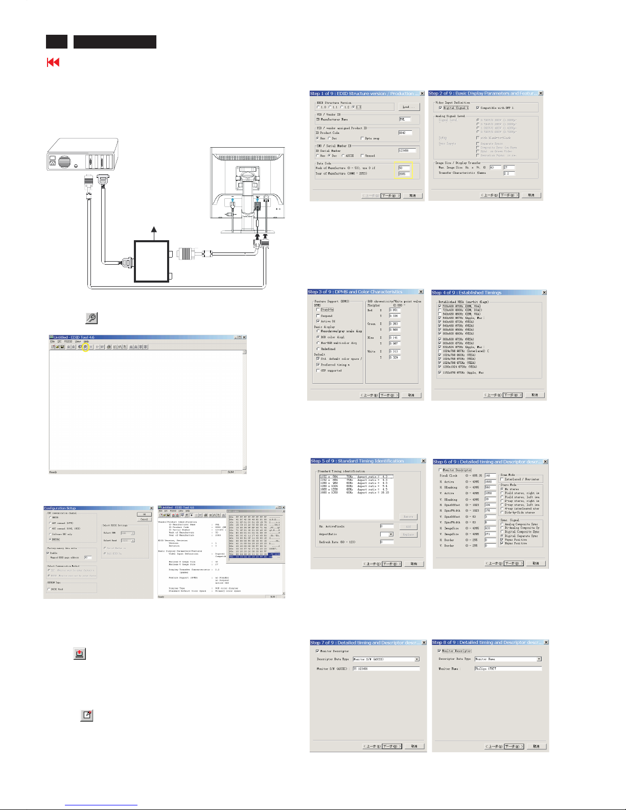
Step 3: Modify DDC data (verify EDID version, week,
year)
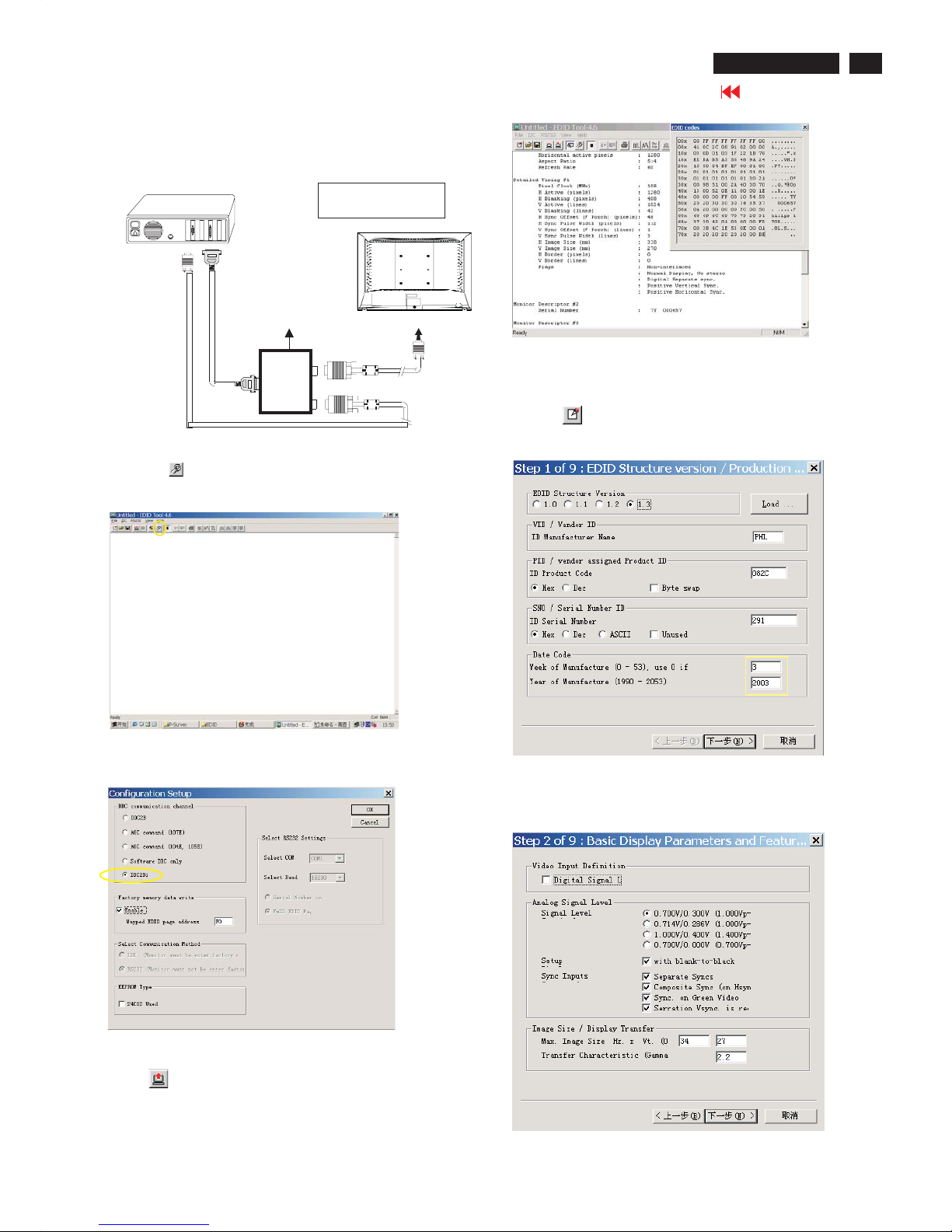
Click (new function) icon from the tool bar, bring up
Step 1 of 9 as shown in Fig. 14 .
EDID46 DDC application provides the function selection and
Step 4: Modify DDC data (Monitor Serial No.)
1. Click Next , bring up Fig. 15.
3. Click OK button to confirm your selection.
4. Click icon (Read EDID function) to read DDC EDID data from
monitor. The EDID codes will display on screen as shown in Fig. 13.
Fig. 15
2. Select the DDC2Bi as the communication channel.
As shown in Fig. 12.
Fig. 12
Fig. 13
Fig. 14
Select and fill out,
If necessary.
Re-programming Analog DDC IC
Step 1: After initialize alignment box, connecting all
cables and box as shown in Fig. 10.
Step 2: Read DDC data from monitor
1. Click icon as shown in Fig. 11 from the tool bar to bring up
the Channels "Configuration Setup" windows as shown in Fig. 11.
Fig. 10
1=Power connector
2=D-SUB connector
PC
To printer port (LTP1)
DC Power
8-12V
Printer
Port
To
Monitor
To P C
1
2
----->
----->
To PC Video port (D-sub)
Click this button
=====>
Fig. 11
20
Go to cover page
DDC Instructions
170C7 LCD
Fig. 21
Fig. 18
Fig. 19
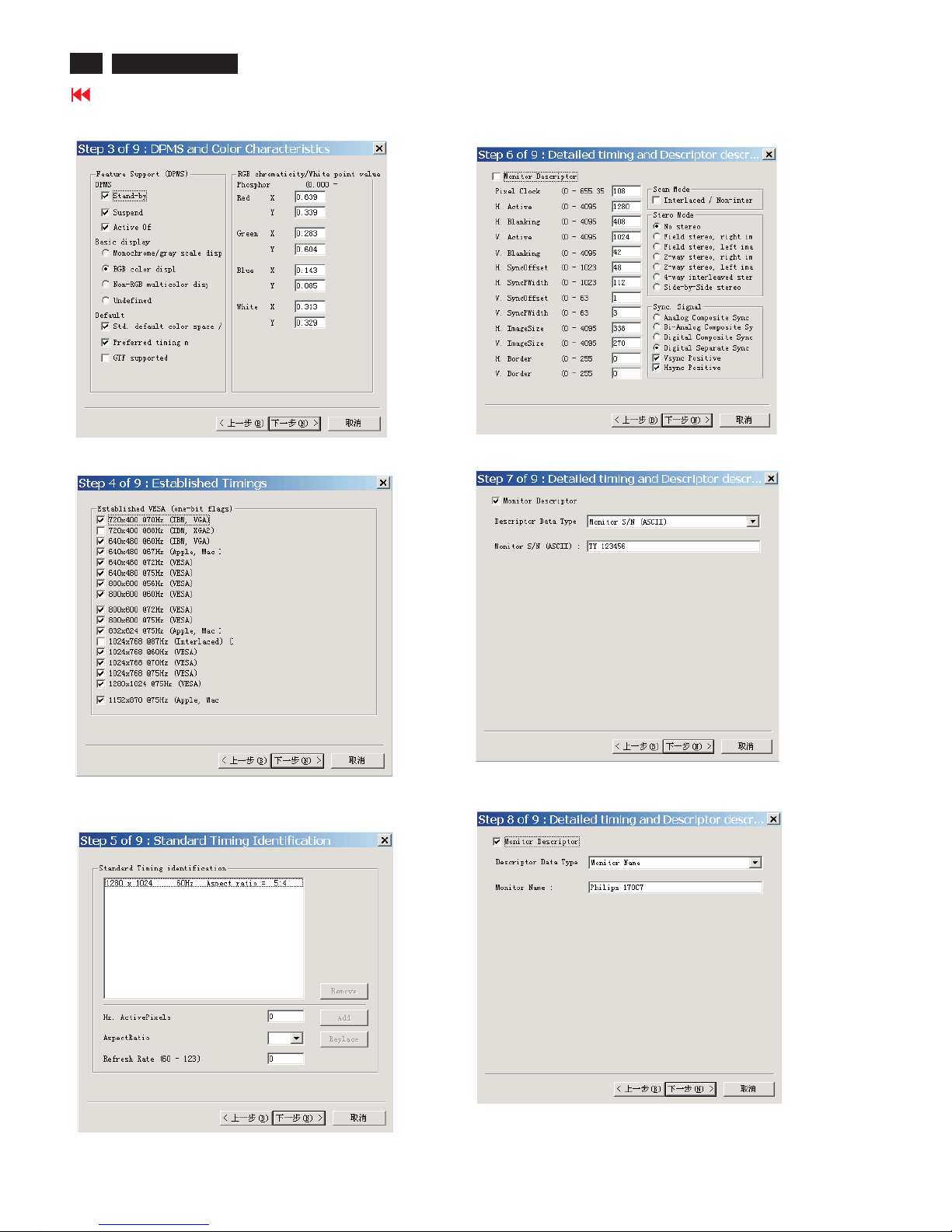
7. Click Next , bring up Fig. 21.
4. Click Next , bring up Fig.18.
5. Click Next , bring up Fig.19.
6. Click Next , bring up Fig. 20.
Fig. 20
2. Click Next , bring up Fig.16.
Fig. 16
Fig. 17
3. Click Next , bring up Fig.17.
21
Go to cover page
DDC Instructions
170C7 LCD
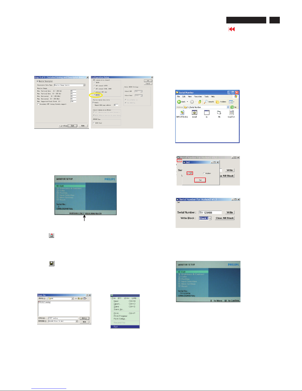
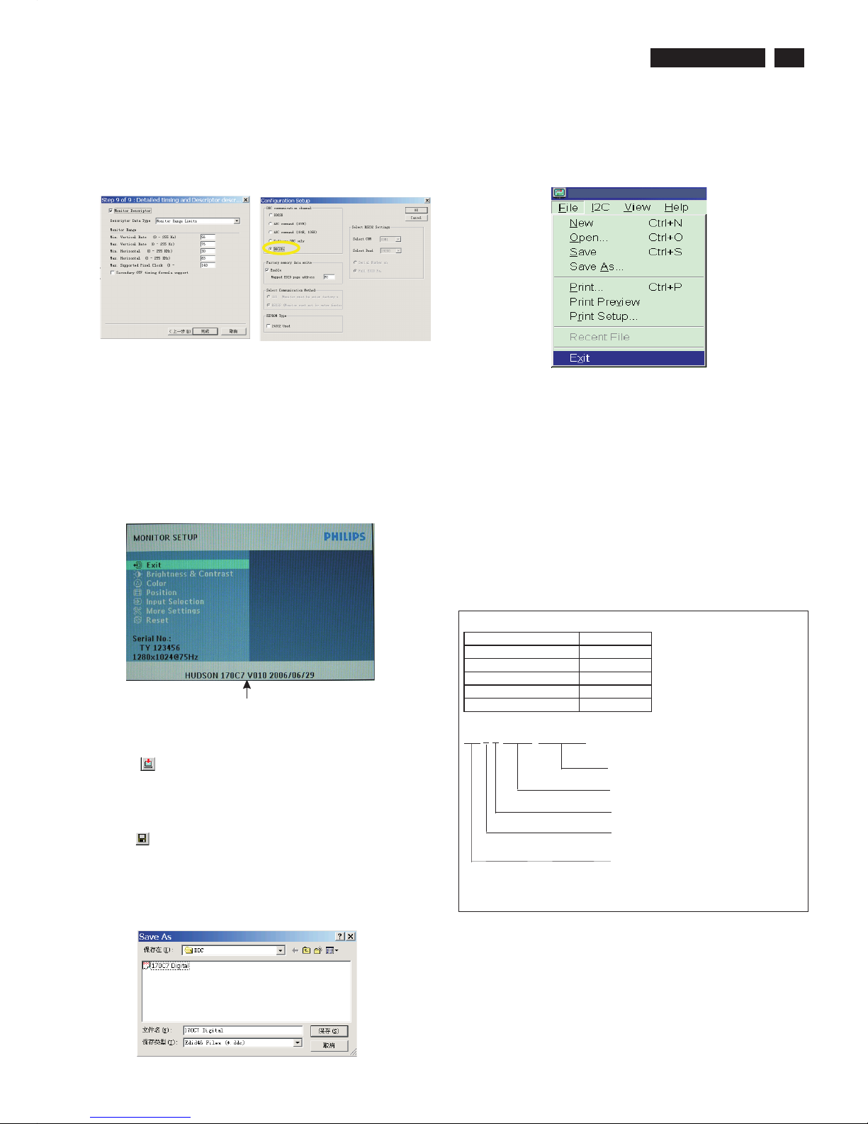
4). Click (Write EDID) icon from the tool bar to write DDC data.
Then wait for 20-30 seconds ,DDC data will be finished Writing.
Fig. 24
3) Push Menu to exit OSD menu.""
Fig. 22
Step 5: Write DDC data
1. Configuration should be as Fig. 23. And press OK.
Fig. 23
2. Click Save.
Step 7: Exit DDC program
Pull down the File menu and select Exit as shown in Fig. 26.
Step 6: Save DDC data
Sometimes, you may need to save DDC data as a text file for
using in other IC chip. To save DDC data, follow the steps below:
1. Click (Save) icon (or click "file"-> "save as") from the tool bar
and give a file name as shown in Fig. 25.
The file type is EDID46 file (*.ddc) which can be open in WordPad.
By using WordPad, the texts of DDC data & table (128 bytes, hex
code) can be modified. If DDC TEXTS & HEX Table ar completely
correct, it can be saved as .ddc flie to re-load it into DDC IC for DDC
Data application.
Fig. 26
Fig. 25
2. Access Factory Mode
1). Turn off monitor.
2).
3).Press "OK" button, wait until the OSD menu with Characters
"HUDSON 170C7 V010 2006/06-29" (below OSD menu) come on
the Screen of the monitor. as shown in Fig24.
[Push "AUTO" & "OK" buttons at the same time and hold them]
+[Press "power" button untill comes out "Windows screen" ]
=> then release all buttons
Factory Mode indicator
Step9:
1. Disconnect the monitor power cord and connect it again.
2. Press the OK button to bring up the OSD main manu.
3. Re-confirm the serial Number is updated as shown in Fig.30.
Step 8: Modify serial number in OSD
1. Unzip the serial number.zip to your computer, then open the folder
as shown in Fig.27.
2. If use Win98 OS, you can execute SN.exe directly.
If use Win2000 or XP OS, first, you must execute install.bat, then
execute SN.exe
3. Set I2C bus(press the left-top button of operating window) as shown
in Fig.28, then press " SET" button.
4. Set Block2 as shown in Fig.29
5. key in new serial number, then press " Write" button as shown in
Fig.29 , Click " WRITE" button.
6. It will appear "Serial Number Write OK" , Click "Enter" to finish it.
Fig.27
Fig.28
Fig.29
Fig.30
8. Click Next , bring up Fig. 22.
- In this step, please confirm the Descriptor Data Type is
Monitor Range Limits, and all the items are same as below.
- Click Finish to exit the Step window.
- Serial number can be filled up at this moment (for example, TY
123456).
22
Go to cover page
DDC Instructions
170C7 LCD
Step 3: Modify DDC data (verify EDID version, week,
year)
Click (new function) icon from the tool bar, bring up
Step 1 of 9 as shown in Fig. 35 .
EDID46 DDC application provides the function selection and
text change (select & fill out) from Step 1 to Step 9.
Step 4: Modify DDC data (Monitor Serial No.)
1. Click Next , bring up Fig. 36.
3. Click OK button to confirm your selection.
4. Click icon (Read EDID function) to read DDC EDID data from
monitor. The EDID codes will display on screen as shown in Fig. 34.
Fig. 36
2. Select the DDC2Bi as the communication channel.
As shown in Fig. 33.
Fig. 33
Fig. 34
Fig. 35
Select and fill out,
If necessary.
Re-programming Digital DDC IC
Step 1: After initialize alignment box, connecting all
cables and box as shown in Fig. 31.
Fig. 32
Step 2: Read DDC data from monitor
1. Click icon as shown in Fig. 11 from the tool bar to bring up
the Channels "Configuration Setup" windows as shown in Fig. 32.
Fig. 31
Click this button
=====>
D-sub to DVI-D cable
1=DVI-D connector
2=D-sub connector
3=Power Plug
2
1
3
D-sub cable
DC Power
8 12V
~
PC
To video card
To printer port (LTP1)
To
Monitor
Printer
Port
Fig. 42
Fig. 39
Fig. 40
7. Click Next , bring up Fig. 42.
4. Click Next , bring up Fig. 39.
5. Click Next , bring up Fig. 40.
6. Click Next , bring up Fig. 41.
In this step, please confirm the Descriptor Data Type is
Monitor Range Limits, and all the items are same as below.
Fig. 41
2. Click Next , bring up Fig. 37.
Fig. 37
Fig. 38
3. Click Next , bring up Fig. 38.
23
170C7 LCD
DDC Instructions
3. Click (Write EDID) icon from the tool bar to write DDC data.
Then wait for 20-30 seconds ,DDC data will be finished Writing.
Fig. 45
Fig. 43
Step 5: Write DDC data
1. Configuration should be as Fig. 40. And press OK.
Fig. 44
2. Click Save.
Step 7: Exit DDC program
Pull down the File menu and select Exit as shown in Fig. 47.
Step 8: Turn off the monitor, exit the factory mode.
Fig. 47
3) Push Menu to exit OSD menu.""
Fig.46
Sometimes, you may need to save DDC data as a text file for using in
other IC chip. To save DDC data, follow the steps below:
1. Click (Save) icon (or click "file"-> "save as") from the tool bar and
give a file name as shown in Fig. 46.
The file type is EDID46 file (*.ddc) which can be open in WordPad. By
using WordPad, the texts of DDC data & table (128 bytes, hex code)
can be modified. If DDC TEXTS & HEX Table ar completely correct, it
can be saved as *.ddc flie to re-load it into DDC IC for DDC Data
application.
Step 6: Save DDC data
Factory Mode indicator
Serial Number Definition
BOM Code
Panel Supplier CODE
AUO 1
CPT 2
LPL(LG) 3
QDI 4
CMO 5
BZ1A0625000001
SERIAL NO
YEAR/WEEK
SERVICE VERSION CHANGE CODE
BOM CODE(BILL OF MATERIAL)CODE
SITE CODE(PRODUCTION CENTER)
BZ CODE(AR-CZECH REPUBLIC
VN-HUNGARY(SZR),BZ-SUZHOU
DS-DONGGUAN)
2. Access Factory Mode
1). Turn off monitor.
2).
3).Press "OK" button, wait until the OSD menu with Characters
"HUDSON 170C7 V010 2006/06/29" (below OSD menu) come on
the Screen of the monitor. as shown in Fig24.
[Push "AUTO" & "OK" buttons at the same time and hold them]
+[Press "power" button untill comes out "Windows screen" ]
=> then release all buttons
8. Click Next , bring up Fig. 43.
- In this step, please confirm the Descriptor Data Type is Monitor
Range Limits, and all the items are same as below.
- Click Finish to exit the Step window.
- Serial number can be filled up at this moment (for example, TY
123456).

24
Go to cover page
170C7 LCD
DDC DATA
THE DISPLAY DATA CHANNEL (DDC_2B) CONTENT INCLUDING:
(FOR 170C7 ANALOG FOR CPT PANEL)
**********************************************************************
EDID log file
**********************************************************************
Vendor/Product Identification
ID Manufacturer Name : PHL
ID Product Code : 0848 (HEX.)
ID Serial Number : 123456 (HEX.)
Week of Manufacture : 23
Year of Manufacture : 2006
EDID Version, Revision
Version : 1
Revision : 3
Basic Display Parameters/Features
Video Input Definition : Analog Video Input
0.700V/0.300V (1.00Vpp)
Blank-to-Black Setup
Separate Sync
Composite Sync
Sync on Green
Serration required
Maximum H Image Size : 34
Maximum V Image Size : 27
Display Transfer Characteristic : 2.2
(gamma)
Feature Support (DPMS) : no Standby
no Suspend
Active Off
Display Type : RGB color display
Standard Default Color Space : Primary color space
Preferred Timing Mode : Detailed timing block 1
Color Characteristics
Red X coordinate : 0.645
Red Y coordinate : 0.335
Green X coordinate : 0.283
Green Y coordinate : 0.614
Blue X coordinate : 0.146
Blue Y coordinate : 0.07
White X coordinate : 0.313
White Y coordinate : 0.329
Established Timings
Established Timings I : 720 x 400 @70Hz (IBM,VGA)
640 x 480 @60Hz (IBM,VGA)
640 x 480 @67Hz (Apple,Mac II)
640 x 480 @72Hz (VESA)
640 x 480 @75Hz (VESA)
800 x 600 @56Hz (VESA)
800 x 600 @60Hz (VESA)
Established Timings II : 800 x 600 @72Hz (VESA)
800 x 600 @75Hz (VESA)
832 x 624 @75Hz (Apple,Mac II)
1024 x 768 @60Hz (VESA)
1024 x 768 @70Hz (VESA)
1024 x 768 @75Hz (VESA)
1280 x 1024 @75Hz (VESA)
Manufacturer's timings : 1152 x 870 @75Hz (Apple,Mac II)
Standard Timing Identification #1
Horizontal active pixels : 1280
Aspect Ratio : 5:4
Refresh Rate : 60
Standard Timing Identification #2
Horizontal active pixels : 1152
Aspect Ratio : 4:3
Refresh Rate : 75
Detailed Timing #1
Pixel Clock (MHz) : 108
H Active (pixels) : 1280
H Blanking (pixels) : 408
V Active (lines) : 1024
V Blanking (lines) : 42
H Sync Offset (F Porch) (pixels) : 48
H Sync Pulse Width (pixels) : 112
V Sync Offset (F Porch) (lines) : 1
V Sync Pulse Width (lines) : 3
H Image Size (mm) : 338
V Image Size (mm) : 270
H Border (pixels) : 0
V Border (lines) : 0
Flags : Non-interlaced
: Normal Display, No stereo
: Digital Separate sync.
: Positive Vertical Sync.
: Positive Horizontal Sync.
Monitor Descriptor #2
Serial Number : TY10623123456
Monitor Descriptor #3
Monitor Name : Philips 170C
Monitor Descriptor #4
Monitor Range Limits
Min. Vt rate Hz : 56
Max. Vt rate Hz : 76
Min. Horiz. rate kHz : 30
Max. Horiz. rate kHz : 83
Max. Supported Pixel : 140
No secondary GTF timing formula supported.
Extension Flag : 0
Check sum : BD (HEX.)
**********************************************************************
Analog EDID d ata (128 bytes)
**********************************************************************
0: 00 1: ff 2: ff 3: ff 4: ff 5: ff 6: ff 7: 00
8: 41 9: 0c 10: 48 11: 08 12: 56 13: 34 14: 12 15: 00
16: 17 17: 10 18: 01 19: 03 20: 1f 21: 22 22: 1b 23: 78
24: 2e 25: 39 26: 85 27: a5 28: 55 29: 48 30: 9d 31: 25
32: 12 33: 50 34: 54 35: bf 36: ef 37: 80 38: 81 39: 80
40: 71 41: 4f 42: 01 43: 01 44: 01 45: 01 46: 01 47: 01
48: 01 49: 01 50: 01 51: 01 52: 01 53: 01 54: 30 55: 2a
56: 00 57: 98 58: 51 59: 00 60: 2a 61: 40 62: 30 63: 70
64: 13 65: 00 66: 52 67: 0e 68: 11 69: 00 70: 00 71: 1e
72: 00 73: 00 74: 00 75: ff 76: 00 77: 54 78: 59 79: 31
80: 30 81: 36 82: 32 83: 33 84: 31 85: 32 86: 33 87: 34
88: 35 89: 36 90: 00 91: 00 92: 00 93: fc 94: 00 95: 50
96: 68 97: 69 98: 6c 99: 69 100: 70 101: 73 102: 20 103: 31
104: 37 105: 30 106: 43 107: 0a 108: 00 109: 00 110: 00 111: fd
112: 00 113: 38 114: 4c 115: 1e 116: 53 117: 0e 118: 00 119: 0a
120: 20 121: 20 122: 20 123: 20 124: 20 125: 20 126: 00 127: bd

25
Go to cover page
170C7 LCD
DDC DATA
THE DISPLAY DATA CHANNEL (DDC_2B) CONTENT INCLUDING:
(FOR 170C7 DIGITAL FOR CPT PANEL)
**********************************************************************
EDID log file
**********************************************************************
Vendor/Product Identification
ID Manufacturer Name : PHL
ID Product Code : 0848 (HEX.)
ID Serial Number : 123456 (HEX.)
Week of Manufacture : 23
Year of Manufacture : 2006
EDID Version, Revision
Version : 1
Revision : 3
Basic Display Parameters/Features
Video Input Definition : Digital Video Input
Maximum H Image Size : 34
Maximum V Image Size : 27
Display Transfer Characteristic : 2.2
(gamma)
Feature Support (DPMS) : no Standby
no Suspend
Active Off
Display Type : RGB color display
Standard Default Color Space : Primary color space
Preferred Timing Mode : Detailed timing block 1
Color Characteristics
Red X coordinate : 0.645
Red Y coordinate : 0.335
Green X coordinate : 0.283
Green Y coordinate : 0.614
Blue X coordinate : 0.146
Blue Y coordinate : 0.07
White X coordinate : 0.313
White Y coordinate : 0.329
Established Timings
Established Timings I : 720 x 400 @70Hz (IBM,VGA)
640 x 480 @60Hz (IBM,VGA)
640 x 480 @67Hz (Apple,Mac II)
640 x 480 @72Hz (VESA)
640 x 480 @75Hz (VESA)
800 x 600 @56Hz (VESA)
800 x 600 @60Hz (VESA)
Established Timings II : 800 x 600 @72Hz (VESA)
800 x 600 @75Hz (VESA)
832 x 624 @75Hz (Apple,Mac II)
1024 x 768 @60Hz (VESA)
1024 x 768 @70Hz (VESA)
1024 x 768 @75Hz (VESA)
1280 x 1024 @75Hz (VESA)
Manufacturer's timings : 1152 x 870 @75Hz (Apple,Mac II)
Standard Timing Identification #1
Horizontal active pixels : 1280
Aspect Ratio : 5:4
Refresh Rate : 60
Standard Timing Identification #2
Horizontal active pixels : 1152
Aspect Ratio : 4:3
Refresh Rate : 75
Detailed Timing #1
Pixel Clock (MHz) : 108
H Active (pixels) : 1280
H Blanking (pixels) : 408
V Active (lines) : 1024
V Blanking (lines) : 42
H Sync Offset (F Porch) (pixels) : 48
H Sync Pulse Width (pixels) : 112
V Sync Offset (F Porch) (lines) : 1
V Sync Pulse Width (lines) : 3
H Image Size (mm) : 338
V Image Size (mm) : 270
H Border (pixels) : 0
V Border (lines) : 0
Flags : Non-interlaced
: Normal Display, No stereo
: Digital Separate sync.
: Positive Vertical Sync.
: Positive Horizontal Sync.
Monitor Descriptor #2
Serial Number : TY10623123456
Monitor Descriptor #3
Monitor Name : Philips 170C
Monitor Descriptor #4
Monitor Range Limits
Min. Vt rate Hz : 56
Max. Vt rate Hz : 76
Min. Horiz. rate kHz : 30
Max. Horiz. rate kHz : 83
Max. Supported Pixel : 140
No secondary GTF timing formula supported.
Extension Flag : 0
Check sum : 5C (HEX.)
**********************************************************************
Digital EDID data (128 bytes)
**********************************************************************
0: 00 1: ff 2: ff 3: ff 4: ff 5: ff 6: ff 7: 00
8: 41 9: 0c 10: 48 11: 08 12: 56 13: 34 14: 12 15: 00
16: 17 17: 10 18: 01 19: 03 20: 80 21: 22 22: 1b 23: 78
24: 2e 25: 39 26: 85 27: a5 28: 55 29: 48 30: 9d 31: 25
32: 12 33: 50 34: 54 35: bf 36: ef 37: 80 38: 81 39: 80
40: 71 41: 4f 42: 01 43: 01 44: 01 45: 01 46: 01 47: 01
48: 01 49: 01 50: 01 51: 01 52: 01 53: 01 54: 30 55: 2a
56: 00 57: 98 58: 51 59: 00 60: 2a 61: 40 62: 30 63: 70
64: 13 65: 00 66: 52 67: 0e 68: 11 69: 00 70: 00 71: 1e
72: 00 73: 00 74: 00 75: ff 76: 00 77: 54 78: 59 79: 31
80: 30 81: 36 82: 32 83: 33 84: 31 85: 32 86: 33 87: 34
88: 35 89: 36 90: 00 91: 00 92: 00 93: fc 94: 00 95: 50
96: 68 97: 69 98: 6c 99: 69 100: 70 101: 73 102: 20 103: 31
104: 37 105: 30 106: 43 107: 0a 108: 00 109: 00 110: 00 111: fd
112: 00 113: 38 114: 4c 115: 1e 116: 53 117: 0e 118: 00 119: 0a
120: 20 121: 20 122: 20 123: 20 124: 20 125: 20 126: 00 127: 5c

26
Go to cover page
170C7 LCD
DDC DATA
THE DISPLAY DATA CHANNEL (DDC_2B) CONTENT INCLUDING:
(FOR 190C7 ANALOG FOR LPL PANEL)
**********************************************************************
EDID log file
**********************************************************************
Vendor/Product Identification
ID Manufacturer Name : PHL
ID Product Code : 0849 (HEX.)
ID Serial Number : 123456 (HEX.)
Week of Manufacture : 23
Year of Manufacture : 2006
EDID Version, Revision
Version : 1
Revision : 3
Basic Display Parameters/Features
Video Input Definition : Analog Video Input
0.700V/0.300V (1.00Vpp)
Blank-to-Black Setup
Separate Sync
Composite Sync
Sync on Green
Serration required
Maximum H Image Size : 38
Maximum V Image Size : 30
Display Transfer Characteristic : 2.2
(gamma)
Feature Support (DPMS) : no Standby
no Suspend
Active Off
Display Type : RGB color display
Standard Default Color Space : Primary color space
Preferred Timing Mode : Detailed timing block 1
Color Characteristics
Red X coordinate : 0.639
Red Y coordinate : 0.342
Green X coordinate : 0.297
Green Y coordinate : 0.615
Blue X coordinate : 0.146
Blue Y coordinate : 0.068
White X coordinate : 0.313
White Y coordinate : 0.329
Established Timings
Established Timings I : 720 x 400 @70Hz (IBM,VGA)
640 x 480 @60Hz (IBM,VGA)
640 x 480 @67Hz (Apple,Mac II)
640 x 480 @72Hz (VESA)
640 x 480 @75Hz (VESA)
800 x 600 @56Hz (VESA)
800 x 600 @60Hz (VESA)
Established Timings II : 800 x 600 @72Hz (VESA)
800 x 600 @75Hz (VESA)
832 x 624 @75Hz (Apple,Mac II)
1024 x 768 @60Hz (VESA)
1024 x 768 @70Hz (VESA)
1024 x 768 @75Hz (VESA)
1280 x 1024 @75Hz (VESA)
Manufacturer's timings : 1152 x 870 @75Hz (Apple,Mac II)
Standard Timing Identification #1
Horizontal active pixels : 1280
Aspect Ratio : 5:4
Refresh Rate : 60
Standard Timing Identification #2
Horizontal active pixels : 1152
Aspect Ratio : 4:3
Refresh Rate : 75
Detailed Timing #1
Pixel Clock (MHz) : 108
H Active (pixels) : 1280
H Blanking (pixels) : 408
V Active (lines) : 1024
V Blanking (lines) : 42
H Sync Offset (F Porch) (pixels) : 48
H Sync Pulse Width (pixels) : 112
V Sync Offset (F Porch) (lines) : 1
V Sync Pulse Width (lines) : 3
H Image Size (mm) : 376
V Image Size (mm) : 301
H Border (pixels) : 0
V Border (lines) : 0
Flags : Non-interlaced
: Normal Display, No stereo
: Digital Separate sync.
: Positive Vertical Sync.
: Positive Horizontal Sync.
Monitor Descriptor #2
Serial Number : TY10623123456
Monitor Descriptor #3
Monitor Name : Philips 190C
Monitor Descriptor #4
Monitor Range Limits
Min. Vt rate Hz : 56
Max. Vt rate Hz : 76
Min. Horiz. rate kHz : 30
Max. Horiz. rate kHz : 83
Max. Supported Pixel : 140
No secondary GTF timing formula supported.
Extension Flag : 0
Check sum : E2 (HEX.)
**********************************************************************
Analog EDID data (128 bytes)
**********************************************************************
0: 00 1: ff 2: ff 3: ff 4: ff 5: ff 6: ff 7: 00
8: 41 9: 0c 10: 49 11: 08 12: 56 13: 34 14: 12 15: 00
16: 17 17: 10 18: 01 19: 03 20: 1f 21: 26 22: 1e 23: 78
24: 2e 25: a2 26: a5 27: a3 28: 57 29: 4c 30: 9d 31: 25
32: 11 33: 50 34: 54 35: bf 36: ef 37: 80 38: 81 39: 80
40: 71 41: 4f 42: 01 43: 01 44: 01 45: 01 46: 01 47: 01
48: 01 49: 01 50: 01 51: 01 52: 01 53: 01 54: 30 55: 2a
56: 00 57: 98 58: 51 59: 00 60: 2a 61: 40 62: 30 63: 70
64: 13 65: 00 66: 78 67: 2d 68: 11 69: 00 70: 00 71: 1e
72: 00 73: 00 74: 00 75: ff 76: 00 77: 54 78: 59 79: 31
80: 30 81: 36 82: 32 83: 33 84: 31 85: 32 86: 33 87: 34
88: 35 89: 36 90: 00 91: 00 92: 00 93: fc 94: 00 95: 50
96: 68 97: 69 98: 6c 99: 69 100: 70 101: 73 102: 20 103: 31
104: 39 105: 30 106: 43 107: 0a 108: 00 109: 00 110: 00 111: fd
112: 00 113: 38 114: 4c 115: 1e 116: 53 117: 0e 118: 00 119: 0a
120: 20 121: 20 122: 20 123: 20 124: 20 125: 20 126: 00 127: e2
 Loading...