

Philips 190C1SB/00, 190C1SB/93 Service Manual

Description Page
Important Safety Notice--------------------------------------2
Technical Data--------------------------------------------- 3~5
Installation-------------------------------------------------------6
On Screen Display-----------------------------------------8~9
Lock/unlock, Aging,Factory mode------------------------10
---------------------------------11
Mechanical Instructions ------------------------------12~15
Color adjustment --------------------------------------------16
Electrical instruction ----------------------------------19~20
DDC Instructions & Serial Number -----------------23~29
DDC DA T A -----------------------------------------------30~31
------------------------32~33
Philips Pixel Defect Policy
FAQs (Frequently Asked Questions)--------------17~18
Firmware Upgrade for CPU-
Horizontal frequencies
30-83kHz
TABLE OF CONTENTS
Description Page
-----------------------------------34
Wiring Diagram--------------------------------------------35
Block Diagram----------------------------------------------36
Power Diagram & C.B.A. ---------------------------44~47
Control Diagram & C.B.A. ---------------------------48~49
General product specification----------------------56~85
Exploded V iew ----------------------------------------------86
Repair tips-----------------------------------------------89~90
Repair Flow chart--------------------------------------91~93
Safety Test Requirments-----------------------------------94
Spare/ arts List-----------------------87
Recommended P
Failure Mode Of Panel -
SAFETY NOTICE
Chassis:
22 inch TFT WXGA LCD Colour Monitor
REFERTO BACK COVER FOR
IMPORTANT SAFETY GUIDELINES
ANY PERSON
ATTEMPTING TOSERVICE THIS CHASSIS
MUST FAMILIARIZE
HIMSELF
WITH THE
CHASSIS
AND BE A W ARE OF THE NECESSARY SAFETY PRECAUTIONS
TO BE USED WHEN
SERVICING ELECTRONIC
EQUIPMENT CONTAINING
HIGH VOLTAGES.
CAUTION:
USE
A SEPARATE
ISOLATION TRANSFORMER FOR THIS UNIT WHEN SERVICING.
Published by Philips Consumer Lifestyle Copyright reserved Subject to modification JMay15 2009
Scaler Diagram & C.B.A. ----------------------------37~43
PCBA photos--------------------------------------------------88
LED Diagram & C.B.A. ---------------------------------50~51
GB
USB Diagram & C.B.A.
---------------------------------52~55
MERIDIAN 1
Troubleshooting-----------------------------------------------7
Service Tool-----------------------------------------------21~22
190C1SB/00
312278518590
190C1SB/93
Important Safety Notice
Proper s ervic e and repair is important
to the sa
fe,
reliable
operation of all Philips Consumer Electronics Co
mpany
equipment. The service procedures
re
commended by
Phil
ips and
described in this service manual a
re eff
ect
ive met hod
sof
performing service ope
rations
.Someof
these s ervic
e
operations require the useof tools speciall y designed
for the
purpose. The spe
cial tools should be used w
hen and as
recomm ended.
It is im portant to note tha t this m anual c ontains various
CAUTI ON
S and NOTICES which should be
carefully read in
order to m inimize the risk of personal injury to servic
e
personnel . The possibility exists th
at im
proper
servi
ce
methods may damage the equipment
. It is also important t
o
underst and that these CAUTIONS and NOTICES ARE NOT
EXHAU STIVE. Phil
ips
could not poss ibly know, evaluate and
advise the servic etrade of all concei vable ways i n w
hic
h
service might be done or of the possible hazardous
consequences of each way. Consequently,Philips has not
undertaken any suc
h broad evalua
ti
on. Accordingly
,
who uses a servi ce procedure or tool which is not
recommended by Philipsmust f
irst sati
sfy
himself thoroughly that
neither his safety nor the safeoperation of the equipment will
be jeopardized by t he servi
ce method sel
ect ed.
* * Hereafter throughout this manu
al,
PhilipsConsumer
Electronics Co mpany w
ill
be referred to as Philip
s
.
**
Critical components havingspecial safety characteri stics are
identified with a by the Ref. No. in the parts list and
enclosed within a broken line
(where several critical co
mponents are grouped i n
one area)
along with the safe
ty s
y
mbol on the schematics
or
exploded vie
ws.
Use of substitute replacement parts which do no
t have the
same speci fied safety charact eristic s may create
shock,
fire,
or other hazards .
Under no cir cumstances should th
e original
design be
modified or altered without written permission from Philip
s.
Philips assumes no liabilit
y, express or implied, arisi ng
out of
any unauthorized modification of design.
Servicer assume s all liability.
WARNING
Take care during handling the LCD module with backlight
unit
- Must mount the module using mounting holes arranged in four
corners.
- Do not press on the panel, edge of the frame strongly or electric
shock as this will result in damage to the screen.
- Do not scratch or press on the panel with any sharp objects, such
as pencil or pen as this may result in damage to the panel.
- Protect the module from the ESD as it may damage the electronic
circuit (C -MOS).
-
Make certain that treatment body are grounded through
wrist band.
- Do not leave the
module in high temperature and
in areas of high
humidity for a long time.
- A void contact with water as it may as hort circuit within the module.
-
If the surface of panel become dirty
, please wi
pe it off with a soft
material. (Cleaning with a dirty or rough cloth may damage the
panel.)
FOR PRODUCTS CONTAINING LASER :
DANGER - Invisible laser radiation when open.
AVOID DIRECT EXPOSURE T
O BEAM.
CAUTION - Use of controls or adjustments or
performance of procedures other than
those specified herein may result
in
hazardous radiation exposure.
CAUTION - The use of optical instruments with this
product will increase eye hazard.
TO ENSURE THE CONTINUED RELIABILITY
OF THIS
PRODUCT, USE ONLYORIGINAL
MANUF
ACTURER'S
REPLACEMENT PARTS, WHICH ARE LISTED WITH THEIR P
ART
NUMBERS IN THE PAR
TS LIST SECTION OF
THIS
SERVICE MANUAL.
2 190C1 LCD
190C1 LCD 3
Technical Data
SEC panel
Type NR. : LTM190BT03
Resolution : 1400x900 (WXGA+)
Outside dimensions : 428 (H) x 278(V) x 17.5(D) mm (Typ.)
Pitch (mm) : 0.2835mm x 0.2835mm
Color pixel arrangement
: 14400 horiz. By 900 vert. Pixels RGB
strip arrangement
Display surface
: Hard coating(3H) & Anti-glare
treatment of the front polarizer
Color depth : 16.7M colors
Backlight : 2 CCFL
Active area (W x H) : 408.24mm x 255.15mm
View angle (CR>10) : >=160/160 for H/V (Typ)
Contrast ratio : >=1000:1 (Typ)
White luminance : >=300 nit (Typ)
Color gamut : >=72%
Source IC : LDI,NEC
Response time : <=5 ms (Typ)
Vertical frequency range : 56~76Hz
Scanning frequencies
Hor. : 30 – 83 K Hz
Ver. : 56 - 76 Hz
Video dot rate : < 137 MHz
Power input : 90-264 V AC, 50/60 ± 2 Hz
Power consumption: < 36 W (Typ.)
< 42 W (Max.)
Functions:
(1) D-SUB analog R/G/B separate inputs, H/V sync separated,
Composite (H+V) TTL level, SOG sync
(2)
DVI digital Panel Link TMDS inputs
Ambient temperature: 0 °C - 40 °C
Power input connection
Power cord length : 1.8 M
Power cord type : 3 leads p ower cord with protective earth plug.
Power management
The monitor must comply with the Microsoft On Now specification,
and meet EPA requirements.
Mode HSYNC VSYNC Video Pwr-cons. Indication Rec.
time
< 36 W typ. Powe
r-On
On On active
< 42 W
max.
White LED --
Blinking
White LED
Stand
by
Off Off blanked < 0.8 W
Period: 3sec
On, 3sec Off
< 3 s
DC
Powe
r Off
N/A < 0.5 W LED Off
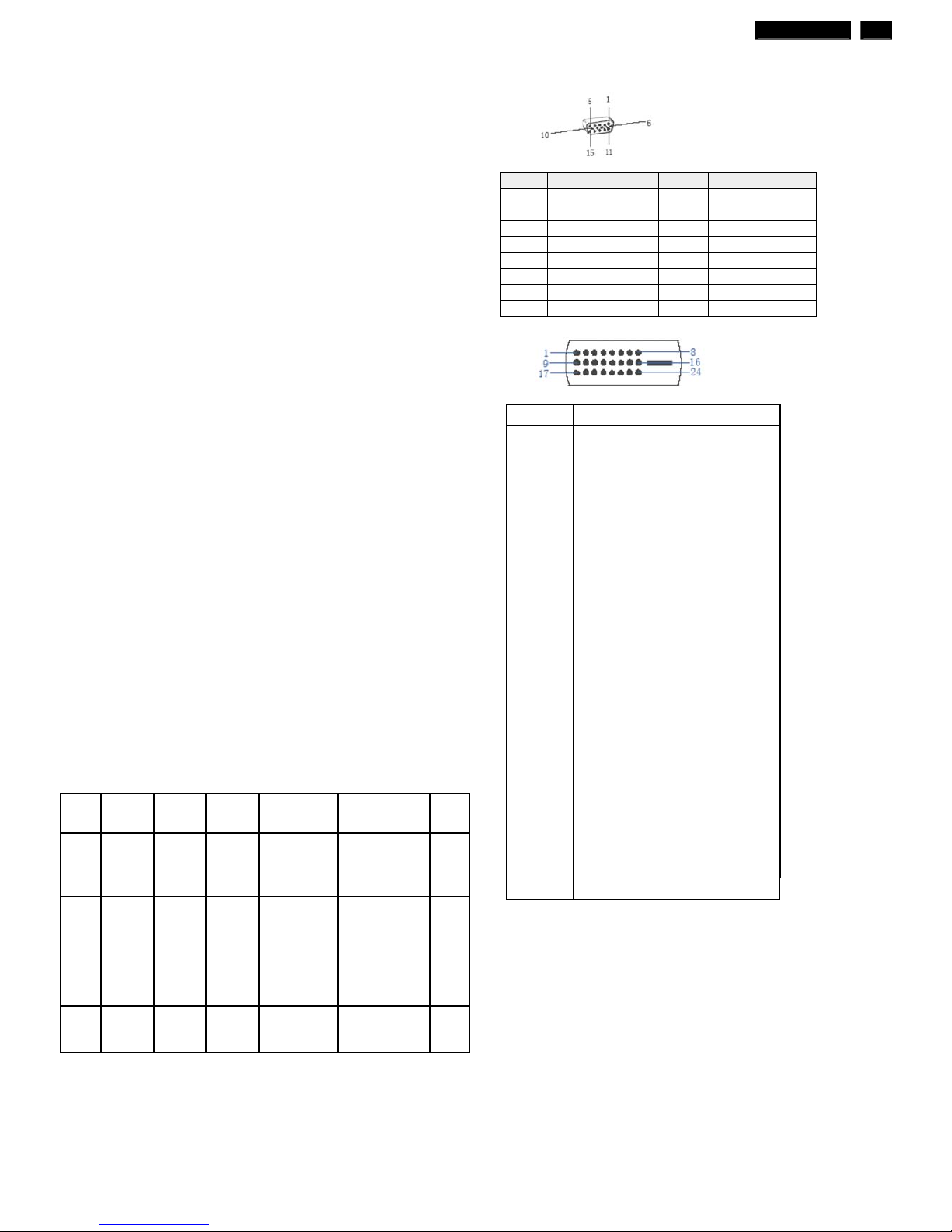
PIN No. SIGNAL PIN No. SIGNAL
1 Red 9 DDC +3.3V or +5V
2 Green/ SOG 10 Logic GND
3 Blue 11 Sense (GND)
4 Sense (GND) 12 Bi-directional data
5 Cable Detect (GND) 13 H/H+V sync
6 Red GND 14 V-sync
7 Green GND 15 Data clock
8 Blue GND
Susceptibility of display to external environment
Operating
- Temperature : 0 to 40 degree C
- Humidity : 80% max
- Altitude : 0-3658m
- Air pressure : 600-1100 mBAR Storage
Storage
- Temperature : -20 to 60 degree C
- Humidity : 95% max
- Altitude : 0-12192m
- Air pressure : 300-1100 mBAR
Note: recommend at 5 to 35°C, Humidity less than 60 %
Pin No. Description
1 T.M.D.S. data22 T.M.D.S. data2+
3 T.M.D.S. data2 shield
4 No Connect
5 No Connect
6 DDC clock
7 DDC data
8 No Connect
9 T.M.D.S. data110 T.M.D.S. data1+
11 T.M.D.S. data1 shield
12 No Connect
13 No Connect
14 +5V Power
15 Ground (for +5V)
16 Hot plug detect
17 T.M.D.S. data018 T.M.D.S. data0+
19 T.M.D.S. data0 shield
20 No Connect
21 No Connect
22 T.M.D.S clock shield
23 T.M.D.S. clock+
24 T.M.D.S. clock-

4 190C1 LCD
Technical Data
LGD panel
Type NR. : LM190WX1-TLL1
Resolution : 1440x900 (WXGA+)
Outside dimensions
: 428.0 (H) x 278.0 (V) x 14.5 (D) mm
(Typ)
Pitch (mm) : 0.2835(H) x 0.2835(V)
Color pixel arrangement : RGB vertical stripe
Display surface : Anti-glare type, Hardness 3H
Color depth : 16.7M colors
Backlight : 2 CCFL
Active area (W x H) : 408.24mm x 255.15mm
View angle (CR>10) : >=170/160 for H/V (Typ)
Contrast ratio : >=1000:1 (Typ)
White luminance : >=250 nit (Typ)
Color gamut : >=72%
Gate IC :
Source IC :
Response time : <=5 ms (Typ)
Vertical frequency range : 56~76Hz
Scanning frequencies
Hor. : 30 – 83 K Hz
Ver. : 56 - 76 Hz
Video dot rate : < 137 MHz
Power input : 90-264 V AC, 50/60 ± 2 Hz
Power consumption: < 36 W (Typ.)
< 42 W (Max.)
Functions:
(1) D-SUB analog R/G/B separate inputs, H/V sync separated,
Composite (H+V) TTL level, SOG sync
(2)
DVI digital Panel Link TMDS inputs
Ambient temperature: 0 °C - 40 °C
Power input connection
Power cord length : 1.8 M
Power cord type : 3 leads p ower cord with protective earth plug.
Power management
The monitor must comply with the Microsoft On Now specification,
and meet EPA requirements.
Mode HSYNC VSYNC Video Pwr-cons. Indication Rec.
time
< 36 W typ. Powe
r-On
On On active
< 42 W
max.
White LED --
Blinking
White LED
Stand
by
Off Off blanked < 0.8 W
Period: 3sec
On, 3sec Off
< 3 s
DC
Powe
r Off
N/A < 0.5 W LED Off
PIN No. SIGNAL PIN No. SIGNAL
1 Red 9 DDC +3.3V or +5V
2 Green/ SOG 10 Logic GND
3 Blue 11 Sense (GND)
4 Sense (GND) 12 Bi-directional data
5 Cable Detect (GND) 13 H/H+V sync
6 Red GND 14 V-sync
7 Green GND 15 Data clock
8 Blue GND
Susceptibility of display to external environment
Operating
- Temperature : 0 to 40 degree C
- Humidity : 80% max
- Altitude : 0-3658m
- Air pressure : 600-1100 mBAR Storage
Storage
- Temperature : -20 to 60 degree C
- Humidity : 95% max
- Altitude : 0-12192m
- Air pressure : 300-1100 mBAR
Note: recommend at 5 to 35°C, Humidity less than 60 %
Pin No. Description
1 T.M.D.S. data22 T.M.D.S. data2+
3 T.M.D.S. data2 shield
4 No Connect
5 No Connect
6 DDC clock
7 DDC data
8 No Connect
9 T.M.D.S. data110 T.M.D.S. data1+
11 T.M.D.S. data1 shield
12 No Connect
13 No Connect
14 +5V Power
15 Ground (for +5V)
16 Hot plug detect
17 T.M.D.S. data018 T.M.D.S. data0+
19 T.M.D.S. data0 shield
20 No Connect
21 No Connect
22 T.M.D.S clock shield
23 T.M.D.S. clock+
24 T.M.D.S. clock-

190C1 LCD 5
Technical Data
CMO panel
Type NR. : M190A1-L0G
Resolution : 1400x900 (WXGA+)
Outside dimensions : 428 (H) x 278(V) x 16.2(D) mm (Typ.)
Pitch (mm) : 0.2835mm x 0.2835mm
Color pixel arrangement
: 14400 horiz. By 900 vert. Pixels RGB
strip arrangement
Display surface
: Hard coating(3H) & Anti-glare
treatment of the front polarizer
Color depth : 16.7M colors
Backlight : 2 CCFL
Active area (W x H) : 408.24mm x 255.15mm
View angle (CR>10) : >=170/160 for H/V (Typ)
Contrast ratio : >=1000:1 (Typ)
White luminance : >=250 nit (Typ)
Color gamut : >=72%
Gate IC :
Source IC :
Response time : <=5 ms (Typ)
Vertical frequency range : 56~76Hz
Scanning frequencies
Hor. : 30 – 83 K Hz
Ver. : 56 - 76 Hz
Video dot rate : < 137 MHz
Power input : 90-264 V AC, 50/60 ± 2 Hz
Power consumption: < 36 W (Typ.)
< 42 W (Max.)
Functions:
(1) D-SUB analog R/G/B separate inputs, H/V sync separated,
Composite (H+V) TTL level, SOG sync
(2)
DVI digital Panel Link TMDS inputs
Ambient temperature: 0 °C - 40 °C
Power input connection
Power cord length : 1.8 M
Power cord type : 3 leads p ower cord with protective earth plug.
Power management
The monitor must comply with the Microsoft On Now specification,
and meet EPA requirements.
Mode HSYNC VSYNC Video Pwr-cons. Indication Rec.
time
< 36 W typ. Powe
r-On
On On active
< 42 W
max.
White LED --
Blinking
White LED
Stand
by
Off Off blanked < 0.8 W
Period: 3sec
On, 3sec Off
< 3 s
DC
Powe
r Off
N/A < 0.5 W LED Off
PIN No. SIGNAL PIN No. SIGNAL
1 Red 9 DDC +3.3V or +5V
2 Green/ SOG 10 Logic GND
3 Blue 11 Sense (GND)
4 Sense (GND) 12 Bi-directional data
5 Cable Detect (GND) 13 H/H+V sync
6 Red GND 14 V-sync
7 Green GND 15 Data clock
8 Blue GND
Susceptibility of display to external environment
Operating
- Temperature : 0 to 40 degree C
- Humidity : 80% max
- Altitude : 0-3658m
- Air pressure : 600-1100 mBAR Storage
Storage
- Temperature : -20 to 60 degree C
- Humidity : 95% max
- Altitude : 0-12192m
- Air pressure : 300-1100 mBAR
Note: recommend at 5 to 35°C, Humidity less than 60 %
Pin No. Description
1 T.M.D.S. data22 T.M.D.S. data2+
3 T.M.D.S. data2 shield
4 No Connect
5 No Connect
6 DDC clock
7 DDC data
8 No Connect
9 T.M.D.S. data110 T.M.D.S. data1+
11 T.M.D.S. data1 shield
12 No Connect
13 No Connect
14 +5V Power
15 Ground (for +5V)
16 Hot plug detect
17 T.M.D.S. data018 T.M.D.S. data0+
19 T.M.D.S. data0 shield
20 No Connect
21 No Connect
22 T.M.D.S clock shield
23 T.M.D.S. clock+
24 T.M.D.S. clock-
6 190C1 LCD
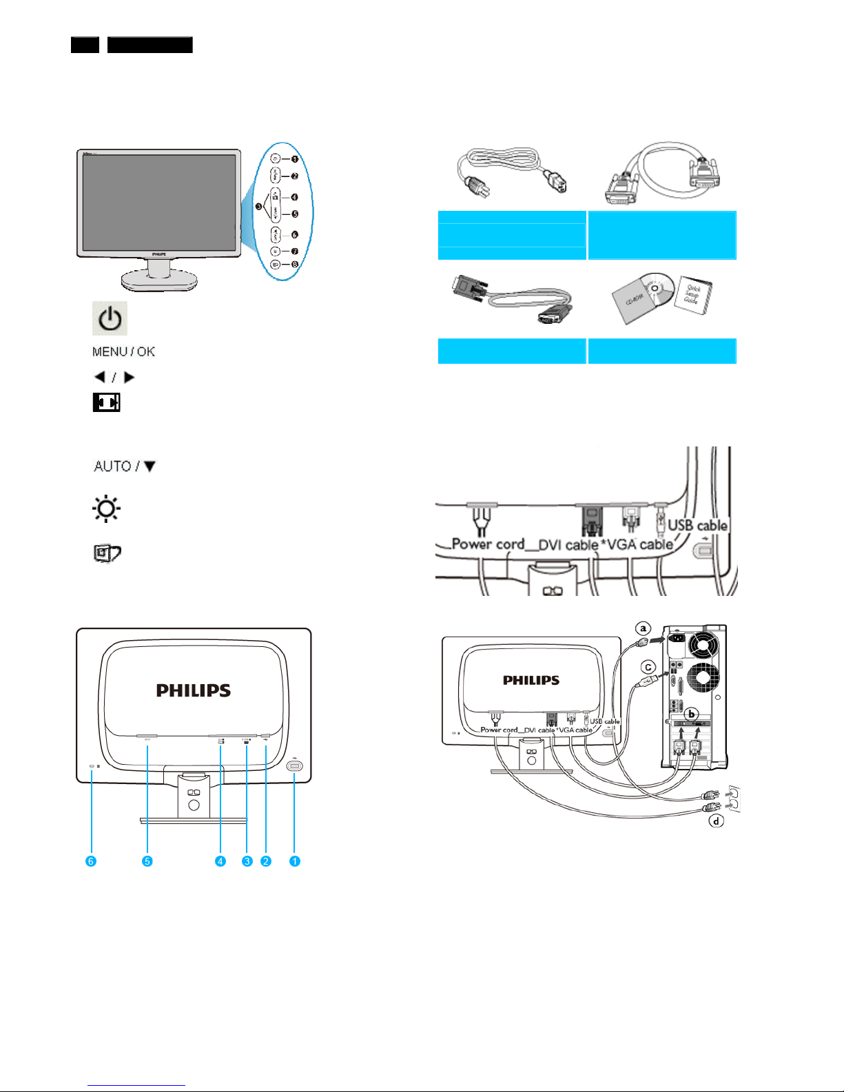
Installation
Front View Product Description
1
To switch monitor's power On and Off
2
To access the OSD menu
3
To adjust the OSD menu
4
Change to 4:3 display
5 Input To change the signal input source
6
Automatically adjust the horizontal
position, vertical position, phase and
clock settings / Return to previous OSD
level
7
To adjust brightness of the display
8
SmartImage. There are five modes to
be selected: Office Work, Image
Viewing, Entertainment, Economy, and
Off
Rear View
Accessory Pack
Unpack all the parts
Power cord
DVI cable
(Optional)
VGA cable EDFU pack
Connecting to Your PC
1) Connect the power cord to the back of the monitor firmly.
(Philips has pre-connected VGA cable for the first installation.
2) Connect to PC
(a) Turn off your computer and unplug its power cable.
(b) Connect the monitor signal cable to the video connector on
the back of your computer.
(c) Connect the USB cable to the USB port of your computer.
(d) Plug the power cord of your computer and your monitor into
a nearby outlet.
(e) Turn on your computer and monitor. If the monitor displays
an image, installation is complete.
1 USB downstream port
2 USB upstream port
3 VGA input
4 DVI-D input (available for selective models)
5 AC power input
6 Kensington anti-thief lock
190C1 LCD 7
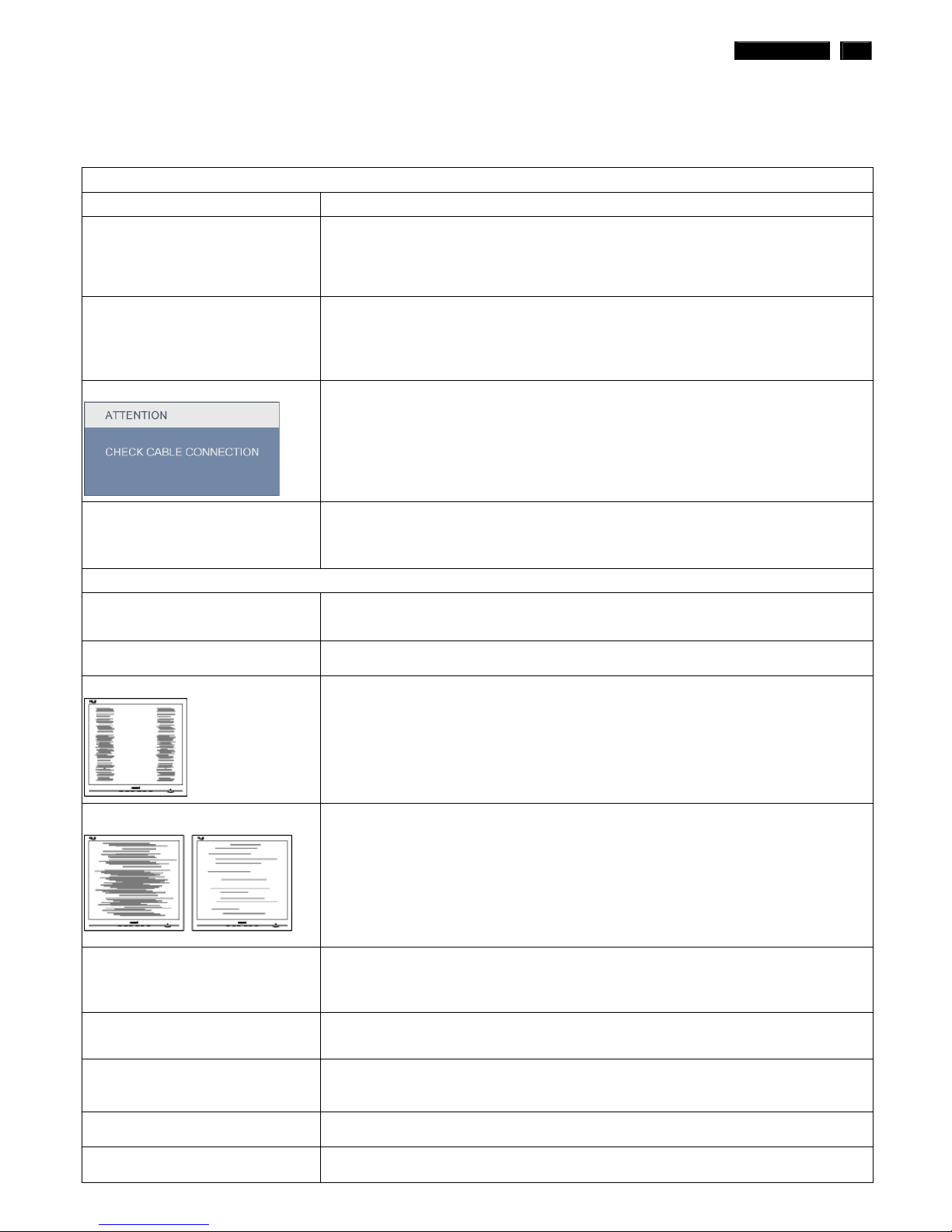
Troubleshooting
This page deals with problems that can be corrected by a user. If the problem still persists after you have tried these
solutions, contact Philips customer service representative.
Common Problems
Having this problem Check these items
No Picture
(Power LED not lit)
1. Make sure the power cord is plugged into the power outlet and into the back of
the monitor.
2. First, ensure that the power button on the front of the monitor is in the OFF position,
then press it to the ON position.
No Picture
(Power LED is blinking)
1. Make sure the computer is turned on.
2. Make sure the signal cable is properly connected to your computer.
3. Check to see if the monitor cable has bent pins.
4. The Energy Saving feature may be activated
Screen says
1. Make sure the monitor cable is properly connected to your computer.
(Also refer to the Quick Set-Up Guide).
2. Check to see if the monitor cable has bent pins.
3. Make sure the computer is turned on.
AUTO button not working properly
1. The Auto Function is designed for use on standard Macintosh or IBM-compatible
PCs running Microsoft Windows.
2. It may not work properly if using nonstandard PC or video card.
Imaging Problems
Display position is incorrect
1. Press the Auto button.
2. Adjust the image position using the Phase/Clock of Setup in OSD Main Controls.
Image vibrates on the screen 1. Check that the signal cable is properly connected to the graphics board or PC.
Vertical flicker appears
1. Press the Auto button.
2. Eliminate the vertical bars using the Phase/Clock of Setup in OSD Main Controls.
Horizontal flicker appears
1. Press the Auto button.
2. Eliminate the vertical bars using the Phase/Clock of Setup in OSD Main Controls.
The screen is too bright or too dark
1. Adjust the contrast and brightness on On-Screen Display. (The backlight of the LCD
monitor has a fixed life span. When the screen becomes dark or begins to flicker, please
contact your sales representative).
An after-image appears
1. If an image remains on the screen for an extended period of time, it may be imprinted in
the screen and leave an after-image. This usually disappears after a few hours
An after-image remains after the power
has been turned off.
1. This is characteristic of liquid crystal and is not caused by a malfunction or deterioration
of the liquid crystal. The after-image will disappear after a period of time.
Green, red, blue, dark, and white dots
remains
1. The remaining dots are normal characteristic of the liquid crystal used in today’s
technology.
Adjust blue "power on" light 1. Adjust blue "power on" light using the power LED of Setup in OSD Main Controls.
8 190C1 LCD
On-Screen Display
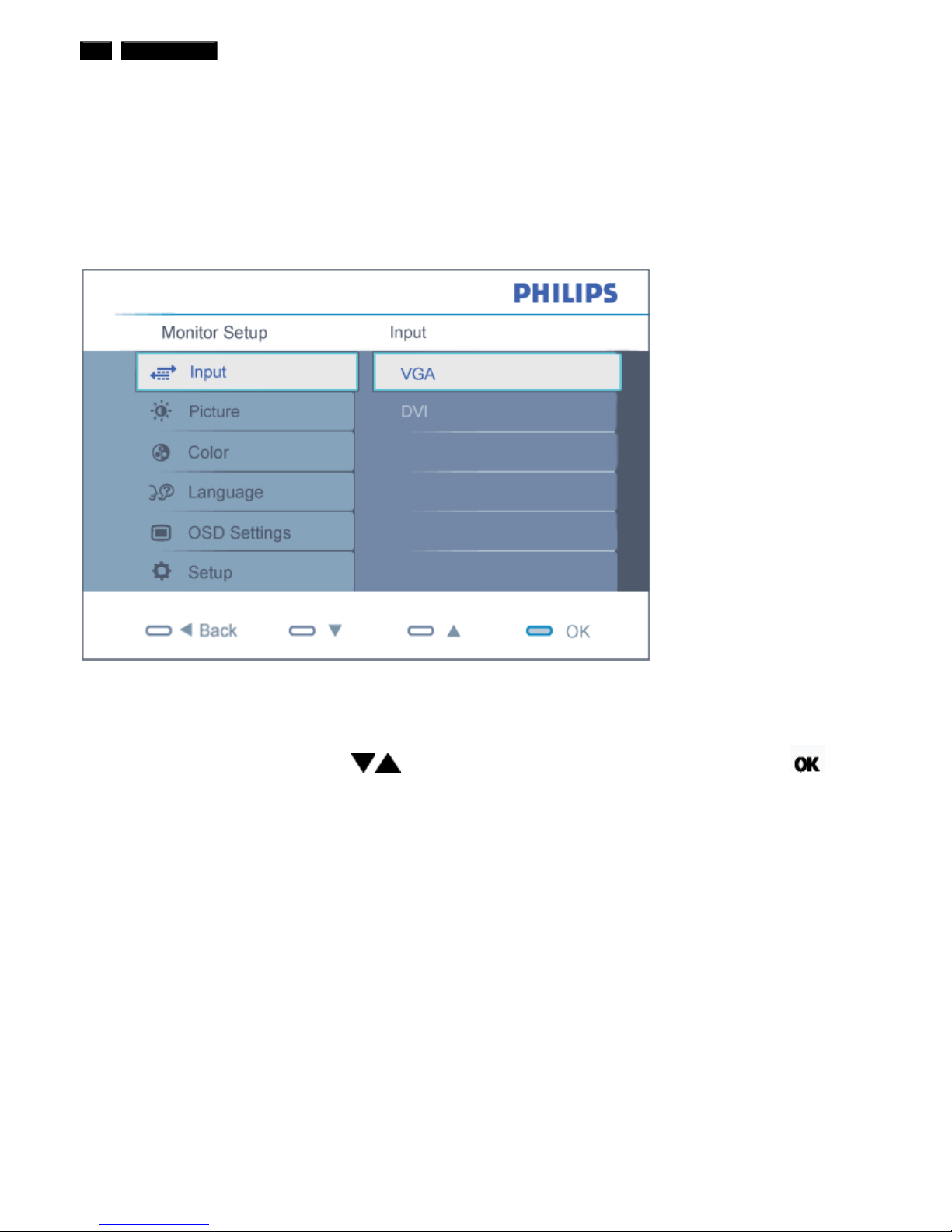
Description of the On Screen Display
What is the On-Screen Display?
On-Screen Display (OSD) is a feature in all Philips LCD monitors. It allows an end user to adjust screen performance or
select functions of the monitors directly through an on-screen instruction window. A user friendly on screen display
interface is shown as below
Basic and simple instruction on the control keys.
In the OSD shown above users can press
buttons at the front bezel of the monitor to move the cursor, to
confirm the choice or change.
190C1 LCD 9
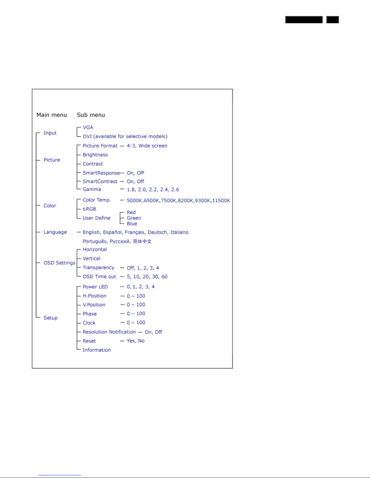
On-Screen Display
The OSD Tree
Below is an overall view of the structure of the On-Screen Display. You can use this as a reference when you want to work
your way around the different adjustments later on.
Resolution notification
This monitor is designed for optimal performance at its native resolution, 1440x900@60Hz. When the monitor is powered
on at a different resolution, an alert is displayed on screen: Use 1440x900@60Hz for best results.
Display of the native resolution alert can be switched off from Setup in the OSD (On Screen Display) menu.
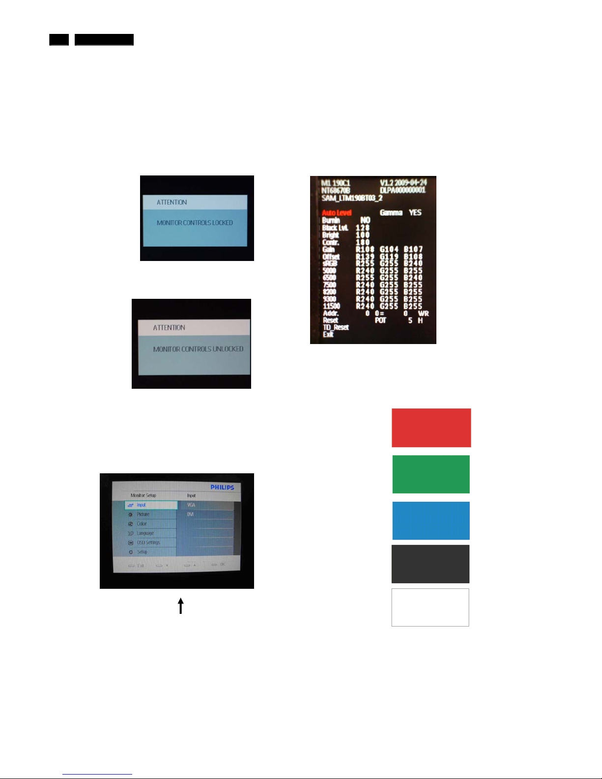
Lock/Unlock,Aging,Factory Mode
To lock/unlock OSD FUNCTION(User Mode)
The OSD function can be locked by pressing"OK"button(1) for more than 10
seconds, the screen shows following windows for 4 seconds. Every time
when you press"OK" button, this message appears on the screen
automatically .
Unlock OSD function
Unlocked OSD function can be released by pressing "OK" button for more
than 10 seconds again.
Access Factory Mode
1). Turn off monitor.
2). [Push "EXIT" & "MENU" buttons at the same time and hold them]+[Press
"power" button until comes out "Windows screen" ] => then release all
buttons
3).Press "MENU" button, wait until the OSD menu with Characters
"MERIDIAN 190C1 V1.2 2009-04-24” (below OSD menu) come on the
Screen of the monitor.
Factory Mode indicator
Factory Menu
Cursor can move on gray color area
Hot key function: by pressing " UP " and " DOWN " key Simultaneously at
User Mode (or Factory Mode) (PS: The Of fset R G B function can be used
on reduce or eliminate snowy noise on the background when the resolution
of video signal is 1680*1050vertical 60Hz. Slightly increase or decrease the
value until snowy noise completely disappear .
Access Aging Mode
Step 1 : Access Factory Mode then enter Factory Menu.
Step 2 : By pressing " UP" and " DOWN " key to Burning Icon. Press
"MENU then press " UP" and "DOWN " key to turn on Aging Mode.
Step 3 : Disconnect interface cable between Monitor and PC.
After 3 seconds,
bring up:
repeatly
Connect Signal cable again=> go back to normal display
10 190C1 LCD

190C1 LCD 11
Philips Pixel Defect Policy
Philips' Flat Panel Monitors Pixel Defect Policy
Philips strives to deliver the highest quality products. We use some of the
industry's most advanced manufacturing processes and practice stringent
quality control. However, pixel or sub pixel defects on the TFT LCD panels
used in flat panel monitors are sometimes unavoidable. No manufacturer
can guarantee that all panels will be free from pixel defects, but Philips
guarantees that any monitor with an unacceptable number of defects will be
repaired or replaced under warranty. This notice explains the different types
of pixel defects and defines acceptable defect levels for each type. In order
to qualify for repair or replacement under warranty, the number of pixel
defects on a TFT LCD panel must exceed these acceptable levels. For
example, no more than 0.0004% of the sub pixels on a 19" XGA monitor may
be defective. Furthermore, Philips sets even higher quality standards for
certain types or combinations of pixel defects that are more noticeable than
others. This policy is valid worldwide.
Pixels and Sub pixels
A pixel, or picture element, is composed of three sub pixels in the primary
colors of red, green and blue. Many pixels together form an image. When all
sub pixels of a pixel are lit, the three colored sub pixels together appear as a
single white pixel. When all are dark, the three colored sub pixels together
appear as a single black pixel. Other combinations of lit and dark sub pixels
appear as single pixels of other colors.
Ty pes of Pixel Defects
Pixel and sub pixel defects appear on the screen in different ways. There are
two categories of pixel defects and several types of sub pixel defects within
each category.
Bright Dot Defects Bright dot defects appear as pixels or sub pixels that are
always lit or 'on'. That is, a bright dot is a sub-pixel that stands out on the
screen when the monitor displays a dark pattern. There are the types of
bright dot defects:
One lit red, green or
blue sub pixel
Two adjacent lit sub
pixels:
- Red + Blue =
Purple
- Red + Green =
Yellow
- Green + Blue =
Cyan (Light Blue)
Three adjacent lit sub
pixels (one white
pixel)
A red or blue bright dot must be more than 50 percent brighter
than neighboring dots while a green bright dot is 30 percent
brighter than neighboring dots.
Black Dot Defects Black dot defects appear as pixels or sub pixels that are
always dark or 'off'. That is, a dark dot is a sub-pixel that stands out on the
screen when the monitor displays a light pattern. These are the types of
black dot defects:
One dark sub pixel Two or three adjacent dark sub pixels
Proximity of Pixel Defects
Because pixel and sub pixels defects of the same type that are near to one
another may be more noticeable, Philips also specifies tolerances for the
proximity of pixel defects.
Pixel Defect Tolerances
In order to qualify for repair or replacement due to pixel defects during the
warranty period, a TFT LCD panel in a Philips flat panel monitor must have
pixel or sub pixel defects exceeding the tolerances listed in the following
tables.
BRIGHT DOT DEFECTS
ACCEPTABLE
LEVEL
MODEL
190C1
1 lit subpixel 3
2 adjacent lit subpixels 1
3 adjacent lit subpixels (one white pixel) 0
Distance between two bright dot defects* >15mm
Total bright dot defects of all types 3
BLACK DOT DEFECTS
ACCEPTABLE
LEVEL
MODEL
190C1
1 dark subpixel 5
2 adjacent dark subpixels 2
3 adjacent dark subpixels 0
Distance between two black dot defects* >15mm
Total black dot defects of all types 5
TOTAL DOT DEFECTS
ACCEPTABLE
LEVEL
MODEL
190C1
Total bright or black dot defects of all types 5
Note:
* 1 or 2 adjacent sub pixel defects = 1 dot defect

12 190C1 LCD
0HFKDQLFDO,QVWUXFWLRQ
Preparation before disassemble
1.Clean the room for disassemble
2.Identify the area for monitor
3.Check the position that the monitors be placed and the quantity of the monitor ;prepare the area for material flow;
according to the actual condition plan the disassemble layout
4.Prepare the implement, equipments, materials as bellow:
1) Press-fixture
2) working table
3) Screw-driver
4) knife*1
5) glove
6) cleaning cloth
7) ESD protection
8) plus driver
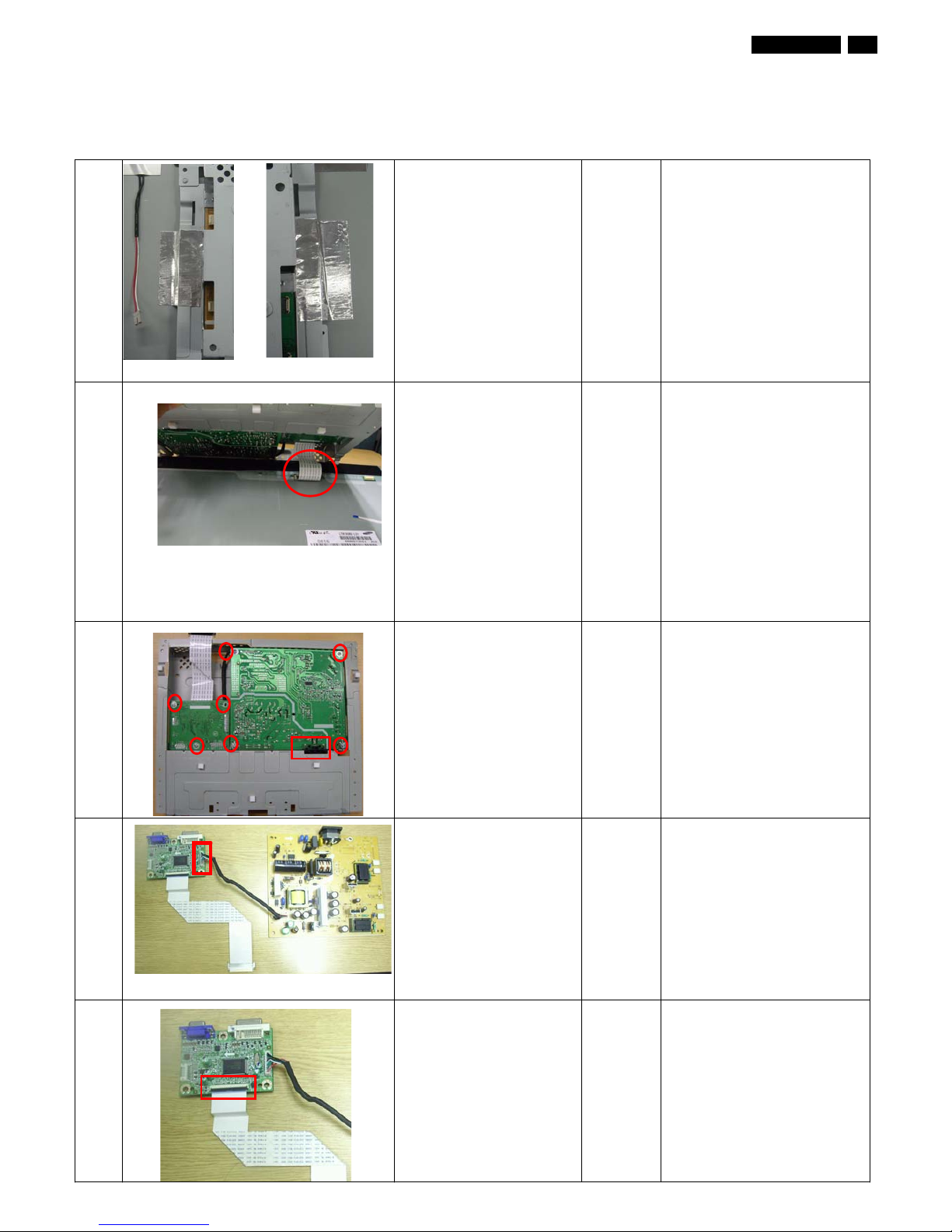
item picture Operation Tool Notes
1
Disassemble the base,
press the circular button
Bring the hinge
2 Disassemble the clip, use
a small screw-driver prize
up
Screwdriver
3 Disassemble the stand,
Æ 6 screws
plus
driver
4 disassembly the bezel
from the monitor, notice
the disassembly order :
1.Top (1) parts of bezel
2.Left (2) parts of bezel
3.Bottom (3) parts of bezel
4. Right (4) parts of bezel
Don’t draw the BZL
When disassembly the
bezel ,notice don’t bend the
C/B .man must wear glove
The purpose is loose the BZL
1
2
3
4
5 Turn over the
monitor ,Uplift the Rear
cover from the monitor
Don’t dismantle the Rear
cover
6 Tear off the AL tape
7 Draw the ffc cable
Take off the rear cover
8 Tear off these two acetic
tapes
Take the entire internal
mechanism from Bezel
and then put it on the
cushion
Draw the ffc cable
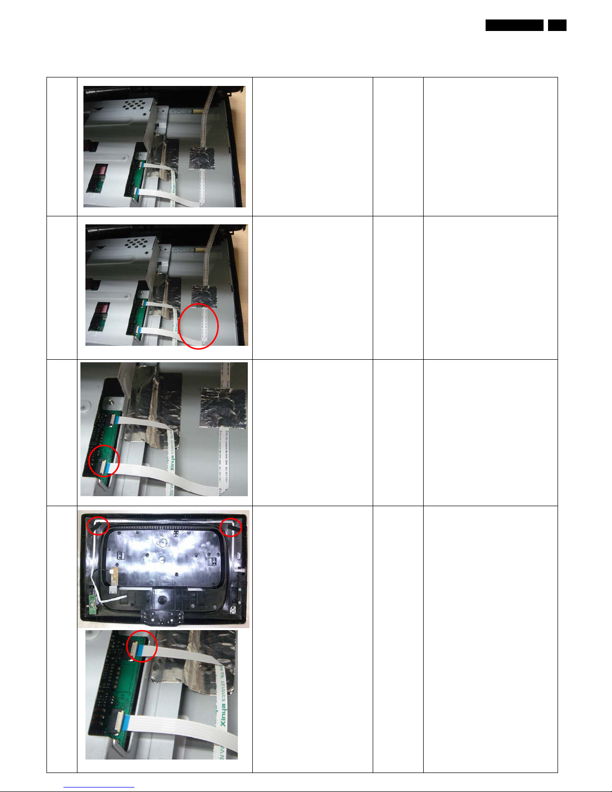
Mechanical Instruction
190C1 LCD 13

9 Disassembled the rear
coverΚ
C/B screw *2
USB screw*1
The other USB screw*1
Then tear off one gasket
on the top of the USB
PCBA.
Plus
driver
10 Disassembled the
Main-BKT : hexagonal
screw *4
Screwdriver
11 Tear off the top AL tape.
12 Tear off this Mylar AL tape
on the top of lamp cable,
Pull out disassemble the
lamp cables
Notes the below PIC
Then the designed Main-BKT
will help to pull out the wires
Man can raise the Lock of
Lamp and then Pull out the
lamp easily
Mechanical Instruction
14 190C1 LCD
13 Tear off the right and left
AL tape
14 Uplift the Main-BKT
unlock the LVDS by using
two hands(see note).
Please carefully use two
hands(one hand presses the
locking-latch of FFC cable’s
housing, and at the same
time another hand pulls out
the FFC cable.) for this step
to avoid from deforming the
terminals of positive-locking
type FFC cable.
15 Disassemble the Power
board
7 screws
Tear off the cover of
AC-SOCKET
Plus
driver
16 Take the PCBA from
Main-BKT and then put it
on the cushion
17
Pull out the cable of
Power board
Notes: Pull the connect
upright
Mechanical Instruction
190C1 LCD 15
16 190C1 LCD
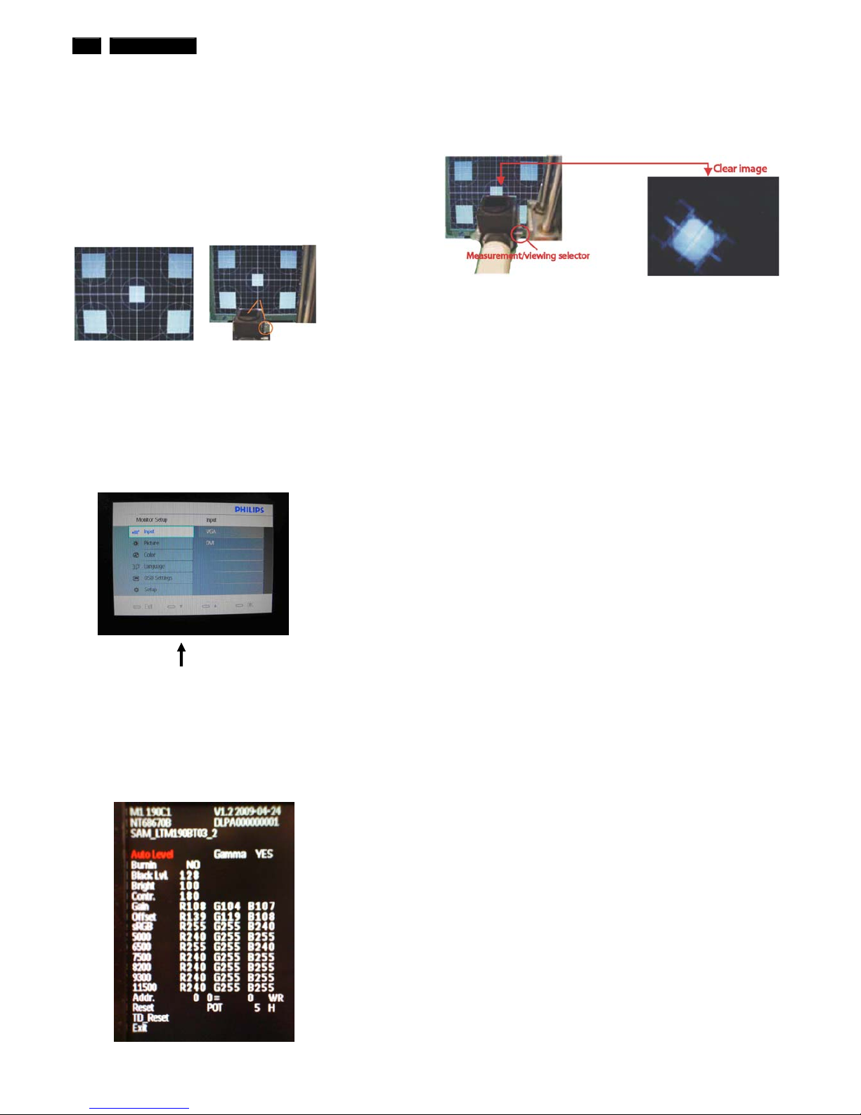
Color Adjustment
Alignment procedure
1. Turn on the LCD monitor .
2. Turn on the Timing/pattern generator. See Fig.1
3. Preset LCD color Analyzer CA-1 10
-Remove the lens protective cover of probe CA-A30.
-Set measuring/viewing selector to measuring position for reset
analyzer .(zero calibration) as Fig.2
- Turn on the color analyzer (CA-1 10)
-Press 0-CAL button to starting reset analyzer .
Fig. 1 Fig.2
4. Access Factory Mode
1). Turn off monitor.
2). [Push "AUT O" & "MENU" buttons at the same time and hold them]
+[Press "power" button untill comes out "Windows screen" ]
=> then release all buttons
3).Press "MENU button, wait until the OSD menu with
Characters" MERIDIAN 190C1 V1.2 2009-04-24 " (below OSD menu)
come on the Screen of the monitor as shown in Fig3.
Factory Mode indicator
Fig. 3
4). Press button, then select factory mode indicator by "MENU" "LEFT"
or "RIGHT" button .Press"MENU" button to bring up submenu
windows as below:
Fig. 4
Fig.5
5.Display
Press "UP" or "DOWN" button to select . Change the value
by "UP" or "DOWN" key until the X, Y co-ordinates as below
5.1
Color temperature adjustment
There are six factory preset white color 11500K, 9300K, 8200K, 7500K,
6500K, sRGB, 5000K
Align by Philips PerfecTune (also called FGA) function.
Apply full white pattern, with brightness in 100 % position and the contrast
control at 50 % position.
The 1931 CIE Chromaticity (color triangle) diagram (x , y) coordinate for
the screen center should be:
Product specification Production alignment spec.
CIE coordinates (x,y) CIE coordinates (x,y)
x = 0.270 ± 0.02 x = 0.270 ± 0.00611500K
y = 0.281 ± 0.02
11500K
y = 0.281 ± 0.006
x = 0.283 ± 0.02 x = 0.283 ± 0.0069300K
y = 0.297 ± 0.02
9300K
y = 0.297 ± 0.006
x = 0.291 ± 0.02 x = 0.291 ± 0.0068200K
y = 0.306 ± 0.02
8200K
y = 0.306 ± 0.006
x = 0.298 ± 0.02 x = 0.298 ± 0.0067500K
y = 0.314 ± 0.02
7500K
y = 0.314 ± 0.006
x = 0.313 ± 0.02 x = 0.313 ± 0.0066500K/sRGB
y = 0.329 ± 0.02
6500K/sRGB
y = 0.329 ± 0.006
x = 0.313 ± 0.02 x = 0.313 ± 0.006sRGB
y = 0.329 ± 0.02
sRGB
y = 0.329 ± 0.006
x = 0.345 ± 0.02 x = 0.345 ± 0.0065000K
y = 0.357 ± 0.02
5000K
y = 0.357 ± 0.006
Quality Inspection specification:
CIE coordinates (x,y)
x = 0.283 ± 0.015 9300K
y = 0.297 ± 0.015
x = 0.313 ± 0.015 6500K/sRGB
y = 0.329 ± 0.015
x = 0.313 ± 0.015 sRGB
y = 0.329 ± 0.015

190C1 LCD 17
FAQs (Frequently Asked Questions)
General FAQs
Q: When I install my monitor what should I do if the screen show s
'Cannot display this video mode'?
A: Recommended video mode for Philips 19": 1440x900 @60Hz.
1. Unplug all cables, then connect your PC to the monitor that you
used previously.
2. In the Windows Start Menu, select Settings/Control Panel. In
the Control Panel Window, select the Display icon. Inside the
Display Control Panel, select the 'Settings' tab. Under the
setting tab, in box labeled 'desktop area', move the slidebar to
1440x900 pixels (19").
3. Open 'Advanced Properties' and set the Refresh Rate to 60Hz,
then click OK.
4. Restart your computer and repeat step 2 and 3 to verify that
your PC is set at 1440x900@60Hz (19").
5. Shut down your computer, disconnect your old monitor and
reconnect your Philips LCD monitor.
6. Turn on your monitor and then turn on your PC.
Q: What are the .inf and .icm files on the CD-ROM? How do I install
the drivers (.inf and .icm)?
A: These are the driver files for your monitor. Follow the instructions in
your user manual to install the drivers. Your computer may ask you for
monitor drivers (.inf and .icm files) or a driver disk when you first install
your monitor. Follow the instructions to insert the ( companion CD-ROM)
included in this package. Monitor drivers (.inf and .icm files) will be
installed automatically.
Q: How do I adjust the resolution?
A: Your video card/graphic driver and monitor together determine the
available resolutions. You can select the desired resolution under
Windows® Control Panel with the "Display properties".
Q: What if I get lost when I am making monitor adjustments?
A: Simply press the MENU button, the Setup button, then select 'Reset'
to recall all of the original factory settings.
Q: What is the Auto function?
A: The AUTO adjustment key restores the optimal screen position, phase
and clock settings by pressing of a single button – without the need to
navigate through OSD (On Screen Display) menus and control keys.
Note: Auto function is available in selected models only.
Q: My Monitor has no power (Power LED does not light up). What
should I do?
A: Make sure the AC power cord is connected between the monitor and
AC outlet, and click a key on keyboard/mouse to wake up the PC.
Q: Will the LCD monitor accept an interlaced signal under PC
models?
A: No. If an Interlace signal is used, the screen displays both odd and
even horizontal scanning lines at the same time, thus distorting the
picture.
Q: What does the Refresh Rate mean for LCD?
A: Unlike CRT display technology, in which the speed of the electron
beam is swept from the top to the bottom of the screen determines flicker,
an active matrix display uses an active element (TFT) to control each
individual pixel and the refresh rate is therefore not really applicable to
LCD technology.
Q: Will the LCD screen be resistant to scratches?
A: A protective coating is applied to the surface of the LCD, which is
durable to a certain extent (approximately up to the hardness of a 2H
pencil). In general, it is recommended that the panel surface is not
subject to any excessive shocks or scratches.
Q: How should I clean the LCD surface?
A: For normal cleaning, use a clean, soft cloth. For extensive cleaning,
please use isopropyl alcohol. Do not use other solvents such as ethyl
alcohol, ethanol, acetone, hexane, etc.
Q:Can I change the color setting of my monitor?
A:Yes, you can change your color setting through OSD control as the
following procedures,
1. Press "MENU" to show the OSD (On Screen Display) menu
2. Press "Down Arrow" to select the option "Color" then press "OK" to
enter color setting, there are three settings as below.
a. Color Temperature; The six settings are 5000K, 6500K, 7500K,
8200K, 9300K and 11500K. With settings in the 5000K range the panel
appears ‘warm,' with a red-white color tone, while a 11500K temperature
yields ‘cool, blue-white toning."
b. sRGB; this is a standard setting for ensuring correct exchange of
colors between different device (e.g. digital cameras, monitors, printers,
scanners, etc)
c. User Define; the user can choose his/her preference color setting by
adjusting red, green blue color.
d. Gamma; The five settings are 1.8, 2.0, 2.2, 2.4, and 2.6.
*A measurement of the color of light radiated by an object while it is being
heated. This measurement is expressed in terms of absolute scale,
(degrees Kelvin). Lower Kelvin temperatures such as 2004K are red;
higher temperatures such as 9300K are blue. Neutral temperature is
white, at 6504K.
Screen Adjustments
Q: When I install my monitor, how do I get the best performance
from the monitor?
A:For best performance, make sure your display settings are set at
1440x900@60Hz for 19".
Q: How do LCDs compare to CRTs in terms of radiation?
A: Because LCDs do not use an electron gun, they do not generate the
same amount of radiation at the screen surface.
Compatibility with other Peripherals
Q: Can I connect my LCD monitor to any PC, workstation or Mac?
A: Yes. All Philips LCD monitors are fully compatible with standard PCs,
Macs and workstations. You may need a cable adapter to connect the
monitor to your Mac system. Please contact your Philips sales
representative for more information.
Q: Are Philips LCD monitors Plug-and-Play?
A: Yes, the monitors are Plug-and-Play comp atible with Windows® 95, 98,
2000, XP and Vista.
Q: What is USB (Universal Serial Bus)?
A: Think of USB as a smart plug for PC peripherals. USB automatically
determines resources (like driver software and bus bandwidth) required
by peripherals. USB makes necessary resources available without user
intervention. There are three main benefits of USB. USB eliminates "case
anxiety," the fear of removing the computer case to install circuit board
cards -- that often requires adjustment of complicated IRQ settings -- for
add-on peripherals. USB does away with "port gridlock." Without USB,
PCs are normally limited to one printer, two Com port devices (usually a
mouse and modem), one Enhanced Parallel Port add-on (scanner or
video camera, for example), and a joystick. More and more peripherals
for multimedia computers come on the market every day . With USB, up to
127 devices can run simultaneously on one computer. USB permits "hot
plug-in." No need to shut down, plug in, reboot and run set up to install
peripherals. No need to go through the reverse process to unplug a
device. Bottom line: USB transforms today's "Plug-and-Pray" into true
Plug-and-Play!
Please refer to glossary for more information about USB.
Q: What is a USB hub ?
A: A USB hub provides additional connections to the Universal Serial Bus.
A hub's upstream port connects a hub to the host, usually a PC. Multiple
downstream ports in a hub allows connection to another hub or device,
such as a USB keyboard, camera or printer.
18 190C1 LCD
FAQs (Frequently Asked Questions)
LCD Panel Technology
Q: What is a Liquid Crystal Display?
A: A Liquid Crystal Display (LCD) is an optical device that is commonly
used to display ASCII characters and images on digital items such as
watches, calculators, portable game consoles, etc. LCD is the technology
used for displays in notebooks and other small computers. Like
light-emitting diode and gas-plasma technologies, LCD allows displays to
be much thinner than cathode ray tube (CRT) technology. LCD consumes
much less power than LED and gas-displays because it works on the
principle of blocking light rather than emitting it.
Q: What differentiates passive matrix LCDs from active matrix
LCDs?
A: An LCD is made with either a passive matrix or an active matrix
display grid. An active matrix has a transistor located at each pixel
intersection, requiring less current to control the luminance of a pixel. For
this reason, the current in an active matrix display can be switched on
and off more frequently, improving the screen refresh time (your mouse
pointer will appear to move more smoothly across the screen, for
example). The passive matrix LCD has a grid of conductors with pixels
located at each intersection in the grid.
Q: What are the advantages of TFT LCD compared with CRT?
A: In a CRT monitor, a gun shoots electrons and general light by colliding
polarized electrons on fluorescent glass. Therefore, CRT monitors
basically operate with an analog RGB signal. A TFT LCD monitor is a
device that displays an input image by operating a liquid crystal panel.
The TFT has a fundamentally different structure than a CRT: Each cell
has an active matrix structure and independent active elements. A TFT
LCD has two glass panels and the space between them is filled with liquid
crystal. When each cell is connected with electrodes and impressed with
voltage, the molecular structure of the liquid crystal is altered and controls
the amount of inlet lighting to display images. A TFT LCD has several
advantages over a CRT, since it can be very thin and no flickering occurs
because it does not use the scanning method.
Q: Why is vertical frequency of 60Hz optimal for an LCD monitor?
A: Unlike a CRT monitor, the TFT LCD panel has a fixed resolution. For
example, an XGA monitor has 1024x3 (R, G, B) x 768 pixels and a higher
resolution may not be available without additional software processing.
The panel is designed to optimize the display for a 65MHz dot clock, one
of the standards for XGA displays. Since the vertical/horizontal frequency
for this dot clock is 60Hz/48kHz, the optimum frequency for this monitor is
60Hz.
Q: What kind of wide-angle technology is available? How does it
work?
A: The TFT LCD panel is an element that controls/displays the inlet of a
backlight using the dual-refraction of a liquid crystal. Using the property
that the projection of inlet light refracts toward the major axis of the liquid
element, it controls the direction of inlet light and displays it. Since the
refraction ratio of inlet light on liquid crystal varies with the inlet angle of
the light, the viewing angle of a TFT is much narrower than that of a CRT.
Usually, the viewing angle refers to the point where the contrast ration is
10. Many ways to widen the viewing angle are currently being developed
and the most common approach is to use a wide viewing angle film,
which widens the viewing angle by varying the refraction ratio. IPS (In
Plane Switching) or MVA (Multi Vertical Aligned) is also used to give a
wider viewing angle.
Q: Why is there no flicker on an LCD Monitor?
A: Technically speaking, LCDs do flicker, but the cause of the
phenomenon is different from that of a CRT monitor -- and it has no
impact of the ease of viewing. Flickering in an LCD monitor relates to
usually undetectable luminance caused by the difference between
positive and negative voltage. On the other hand, CRT flickering that can
irritate the human eye occurs when the on/off action of the fluorescent
object becomes visible. Since the reaction speed of liquid crystal in an
LCD panel is much slower, this troublesome form of flickering is not
present in an LCD display.
Q: Why is an LCD monitor virtually low of Electro Magnetic
Interference?
A: Unlike a CRT, an LCD monitor does not have key parts that generate
Electro Magnetic Interference, especially magnetic fields. Also, since an
LCD display utilizes relatively low power, its power supply is extremely
quiet.
Ergonomics, Ecology and Safety Standards
Q: What is the CE mark?
A: The CE (Conformité Européenne) mark is required to be displayed on
all regulated products offered for sale on the European market. This 'CE'
mark means that a product complies with the relevant European Directive.
A European Directive is a European 'Law' that relates to health, safety,
environment and consumer protection, much the same as the U.S.
National Electrical Code and UL Standards.
Q: Does the LCD monitor conform to general safety standards?
A: Yes. Philips LCD monitors conform to the guidelines of TCO Displays
5.0 standards for the control of radiation, electromagnetic waves, energy
reduction, electrical safety in the work environment and recyclability. The
specification page provides detailed data on safety standards.
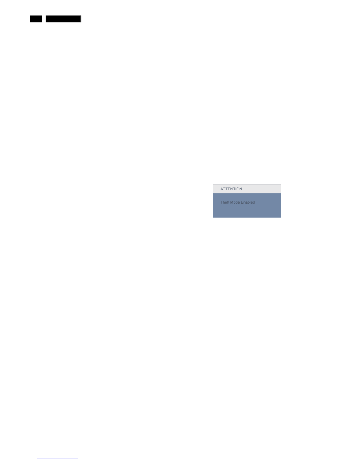
Q: After I change new PC, I found this information on screen, how
can I do?
A: Because you activate Theft Deterrence function in SmartControl II.
Please contact IT manager or Philips Service Center.
225B1 LCD 19
Electrical Instructions
Electrical characteristics
1. Interface signals
1.1. D-Sub Analog
Input signal: Video, Hsync., Vsync c
Video: 0.7 Vp-p, input impedance, 75 ohm @DC
Sync.: Separate sync
TTL level , input impedance 2.2k ohm terminate
Hsync Positive/Negative
Vsync Positive/Negative
Composite sync TTL level, input impedance 2.2k ohm
terminate (Positive/Negative)
Sync on green video 0.3 Vp-p Negative (Video 0.7
Vp-p Positive)
1.2. DVI-D Digital
I Input signal: Single TMDS link
(Three channels: RX0-/+, RX1-/+, RX2-/+)
1.3. USB PLUG support
Input signal: Upstream input (V
BUS
, D+, D-, GND) via
USB-B receptacle.
Output signal: Downstream output (V
BUS
, D+, D-, GND)
through USB-A receptacle
2. Interface
2.1. D-Sub Cable
Length : 1.8 M +/- 50 mm
Fix with monitor when packing, with transplant pin
protective cover.
Connector type : D-Sub male with DDC2B pin
assignments.
Blue connector thumb-operated jack screws
2.2. DVI Cable
The input signals are applied to the display through
DVI-D cable.
Length : 1.8 M +/- 50 mm
Connector type : DVI-D male with DDC-2B pin
assignments
White connector thumb-operated jackscrews
3. Timing requirement
3.1.Factory Preset mode definition:
3.1.1. Perfect FOS while presenting all required timings.
3.1.2. Required timings need to be specified in User's
Manual
3.2. Preset mode definition:
3.2.1. Need to support those timings.
3.2.2. Perfect FOS after auto adjustment.
3.3. 3.3 User mode
3.1.1. Can save those timing that not in Preset
mode and can be showed (not over scalar or
Panel spec.)
3.3.2. It needs to reserve the 12 timings sp ace in
memory size.
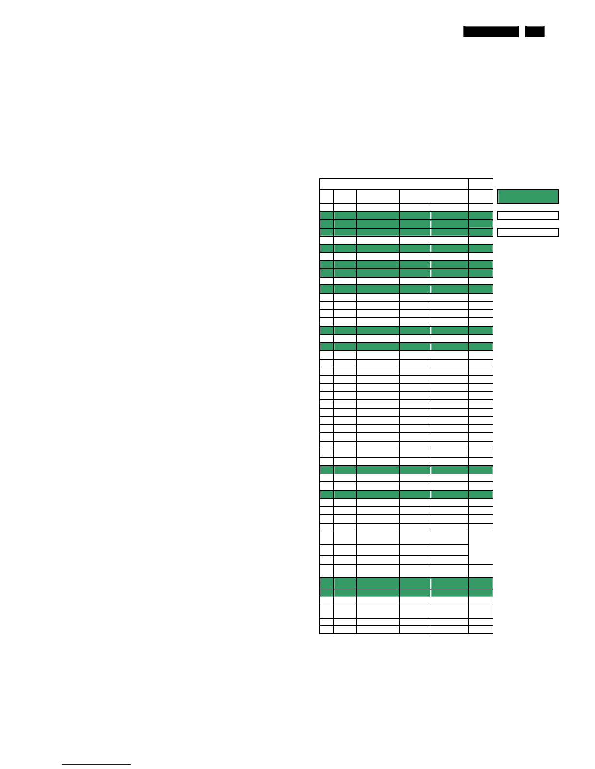
3.3.3 Factory preset modes
19W Preset Mode
Item H.Freq.
(KHz)
Mode Resolution V.Freq. (Hz) BW(MHz) Factory Preset mode:
13 Sets
1 31.469 IBM VGA 10H 640x350 70.086
2 31.469 IBM VGA 3H 720x400 70.087
Preset mode: 50 Sets
3 31.469 IBM VGA 12H 640x480 59.94
4 35 MACINTOSH 640x480 67
User mode: 10 Sets
5 37.861 VESA 640x480 72.809
6 37.5 VESA 640x480 75
7 43.269 VESA 640x480 85.008
8 35.156 VESA 800x600 56.25
9 37.879 VESA 800x600 60.317
10 48.077 VESA 800x600 72.188
11 46.875 VESA 800x600 75
12 53.674 VESA 800x600 85.061
13 49.7 MACINTOSH 832x624 75
14 56.4 - 960x720 75
15 44.75 - 960x720 60
16 48.363 VESA 1024x768 60.004
17 56.476 VESA 1024x768 70.069
18 60.023 VESA 1024x768 75.029
19 61.08 IBM XGA-2 1024x768 75.781
20 68.677 VESA 1024x768 84.997
21
CVT 2.3MA 1280 x768 60
22 60.289 CVT 2.3MA 1280 x768 75
23 54.1
1152x864 60
24 63.851 VESA 1152x864 70.012
25 67.5 VESA 1152x864 75
26 68.7 MACINTOSH 1152x870 75
27 61.845 SUN WS 1152x900 66.004
28 71.81 SUN WS 1152x900 76.15
29 49.7 CVT 1280x800 59.81
30 62.8 CVT 1280x800 74.93
31 60 VESA 1280x960 60
32 75 VESA 1280x960 75
33 63.981 VESA 1280x1024 60.02
34 71.691 SUN WS 1280x1024 67.189
35 76 DOS/V 1280x1024 72
36 79.976 VESA 1280x1024 75.025
37 81.13 SUN WS 1280x1024 76.11
38 91.1 VESA 1280x1024 85
39 44.772 - 1280x720 60
40 52.5 - 1280x720 70
41 64 CVT-reduced
blanking
1400x1050 60
42 80 CVT 1400x1050 75
43 91.1 CVT 1400x1050 85
44 55.469 VESA-reduced
blanking mode
1440x900 59.901 88.75
45 55.935 VESA 1440x900 59.887 106.5
46 70.635 VESA 1440x900 74.984 136.75
47 75 VESA 1600x1200 60 161
48 66.587 CVT 2.3MA-R 1920x1080 60.0 (for
DVI-D
138.5
49 65.29 CVT1.76MW 1680x1050 60 146
50
CVT1.76MW-R 1680x1050 60 119
20 190C1 LCD
Electrical Instructions
Color temperature adjustment
There are six factory preset white color 11500K, 9300K, 8200K, 7500K, 6500K, sRGB, 5000K
Align by Philips PerfecTune (also called FGA) function.
Apply full white pattern, with brightness in 100 % position and the contrast control at 50 % position.
The 1931 CIE Chromaticity (color triangle) diagram (x , y) coordinate for the screen center should be:
Product specification
CIE coordinates (x,y)
11500K x = 0.270 ± 0.02
y = 0.281 ± 0.02
9300K x = 0.283 ± 0.02
y = 0.297 ± 0.02
8200K x = 0.291 ± 0.02
y = 0.306 ± 0.02
7500K x = 0.298 ± 0.02
y = 0.314 ± 0.02
6500K/sRGB x = 0.313 ± 0.02
y = 0.329 ± 0.02
sRGB x = 0.313 ± 0.02
y = 0.329 ± 0.02
5000K x = 0.345 ± 0.02
y = 0.357 ± 0.02
Production alignment spec.
CIE coordinates (x,y)
11500K x = 0.270 ± 0.006
y = 0.281 ± 0.006
9300K x = 0.283 ± 0.006
y = 0.297 ± 0.006
8200K x = 0.291 ± 0.006
y = 0.306 ± 0.006
7500K x = 0.298 ± 0.006
y = 0.314 ± 0.006
6500K/sRGB x = 0.313 ± 0.006
y = 0.329 ± 0.006
sRGB x = 0.313 ± 0.006
y = 0.329 ± 0.006
5000K x = 0.345 ± 0.006
y = 0.357 ± 0.006
Quality Inspection specification:
CIE coordinates
(x,y)
9300K x = 0.283 ± 0.015
y = 0.297 ± 0.015
6500K/sRGB x = 0.313 ± 0.015
y = 0.329 ± 0.015
sRGB x = 0.313 ± 0.015
y = 0.329 ± 0.015
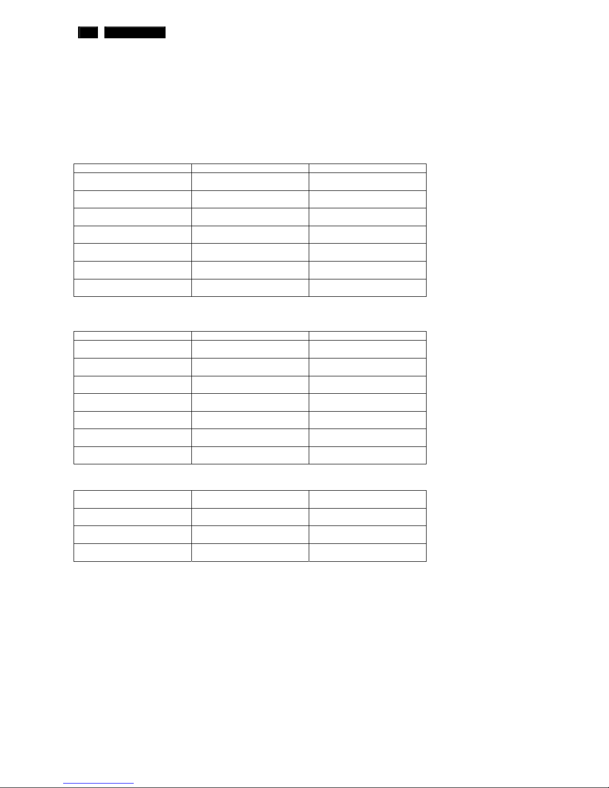
190C1 LCD 21
Service tool-Hardware
PCM code 12NC
5E.L8215.001 996510019769
Service tool-Software
FW writing tool: Easy Writer V4.1
DDC writing tool: Q-EDID-V16
22 190C1 LCD
190C1 LCD 23
DDC Instructions
DDC Data Re-programming
In case the DDC data memory IC or main EEPROM which storage all factory settings were
replaced due to a defect, the serial numbers have to be re-programmed "Analog
DDC IC, Digital DDC IC & EEPROM".
It is advised to re-soldered DDC IC and main EEPROM from the old board onto the new
board if circuit board have been replaced, in this case the DDC data does not need to be
re-programmed.
Additional information
Additional information about DDC (Display Data Channel) may be obtained from Video
Electronics Standards Association (VESA).
Extended Display Identification Data(EDID) information may be also obtained from
VESA.
Configuration and procedure
"PI-EDID" The software is provided by IMS to upgrade the firmware of CPU.
PI-EDID Tools is for the interface between "Parallel Port of PC" and "15 pin-D-SUB
connector of Monitor".
It is a windows-based program, which cannot be run in MS-DOS.
System and equipment requirements
1. An Pentium (or above) personal computer or compatible.
2. Microsoft operation system Windows 95/98/2000/XP and Port95NT.exe.
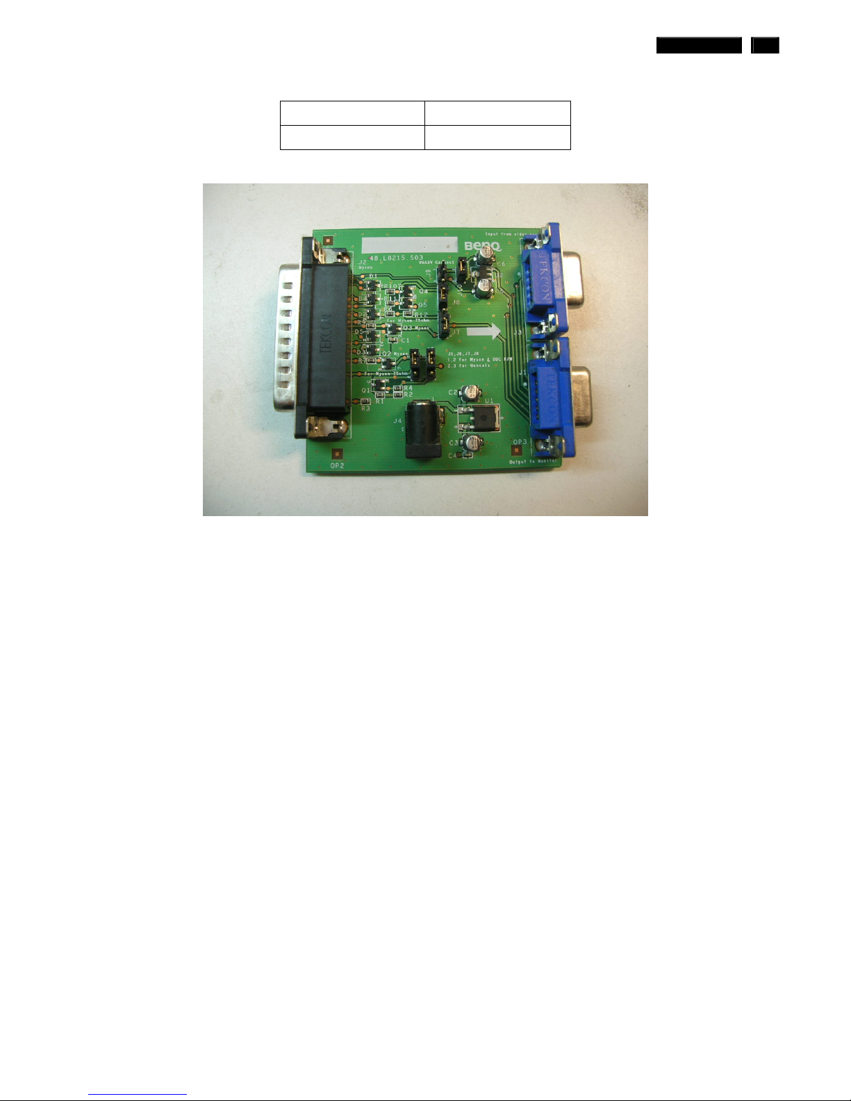
3. EDID Software "PI-EDID.exe"
4. ISP boardas shown in Fig. 1
And I2C Board Jump wire should follow J10 (short), J9 (open), J5/J6/ (1and 2 pin short)
J7/J8 (1 and 2 pin short)
Connected to print
cord and PC
Connected to Display
Signal Cable
1
2
3
2
Fig.1
24 190C1 LCD
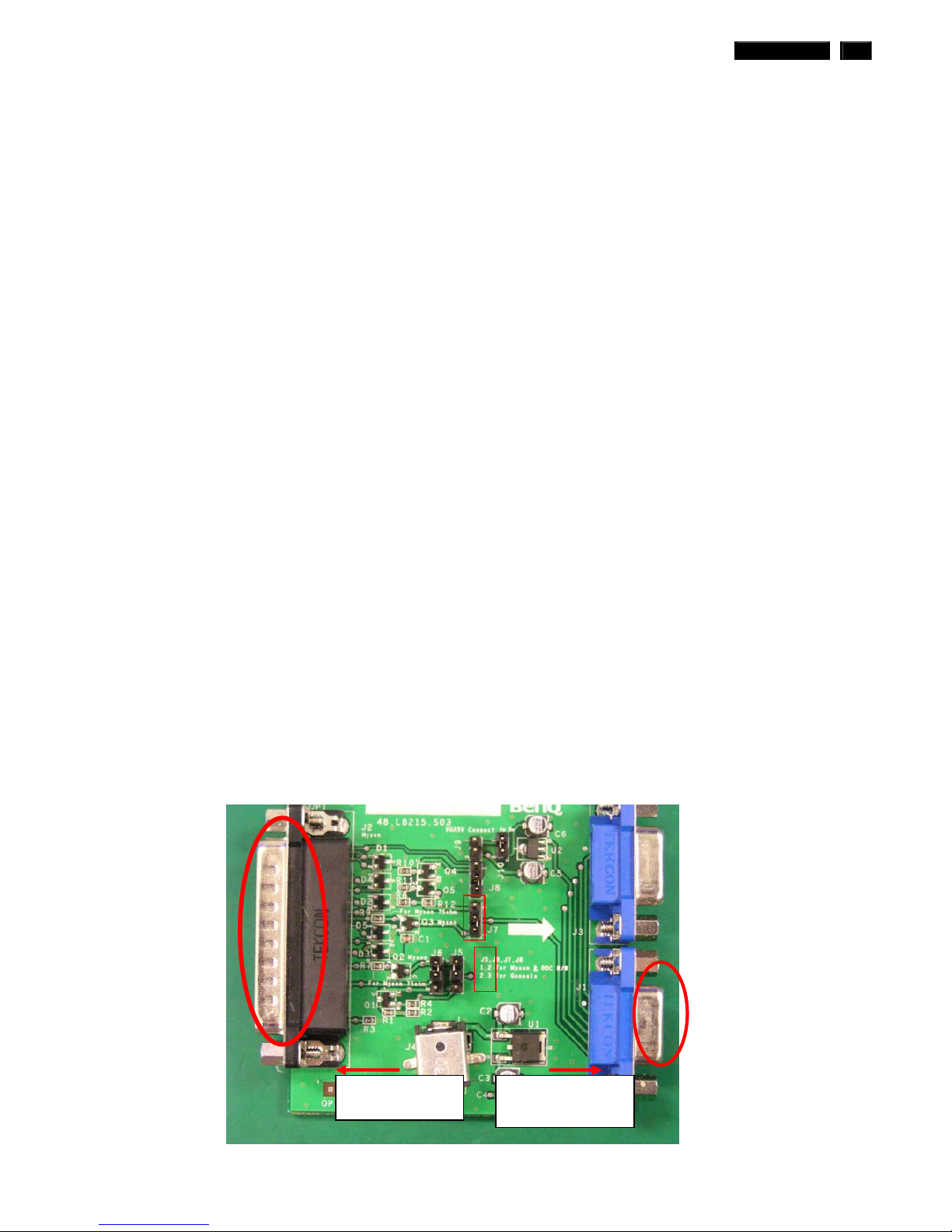
DDC Instructions
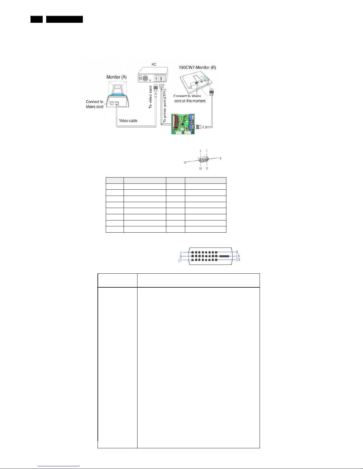
5. Connect and Mains cord to Monitor as shown in Fig.2.
Fig.2
Pin assignments :
A. 15-pin D-Sub Connector
B. Input DVI-D Connector pin
Pin No.
Description
1 T.M.D.S. data22 T.M.D.S. data2+
3 T.M.D.S. data2 shield
4 No Connect
5 No Connect
6 DDC clock
7 DDC data
8 No Connect
9 T.M.D.S. data110 T.M.D.S. data1+
11 T.M.D.S. data1 shield
12 No Connect
13 No Connect
14 +5V Power
15 Ground (for +5V)
16 Hot plug detect
17 T.M.D.S. data018 T.M.D.S. data0+
19 T.M.D.S. data0 shield
20 No Connect
21 No Connect
22 T.M.D.S clock shield
23 T.M.D.S. clock+
24 T.M.D.S. clock-
PIN No. SIGNAL PIN No. SIGNAL
1 Red 9 DDC +3.3V or +5V
2 Green/ SOG 10 Logic GND
3 Blue 11 Sense (GND)
4 Sense (GND) 12 Bi-directional data
5 Cable Detect (GND) 13 H/H+V sync
6 Red GND 14 V-sync
7 Green GND 15 Data clock
8 Blue GND
DDC Instructions
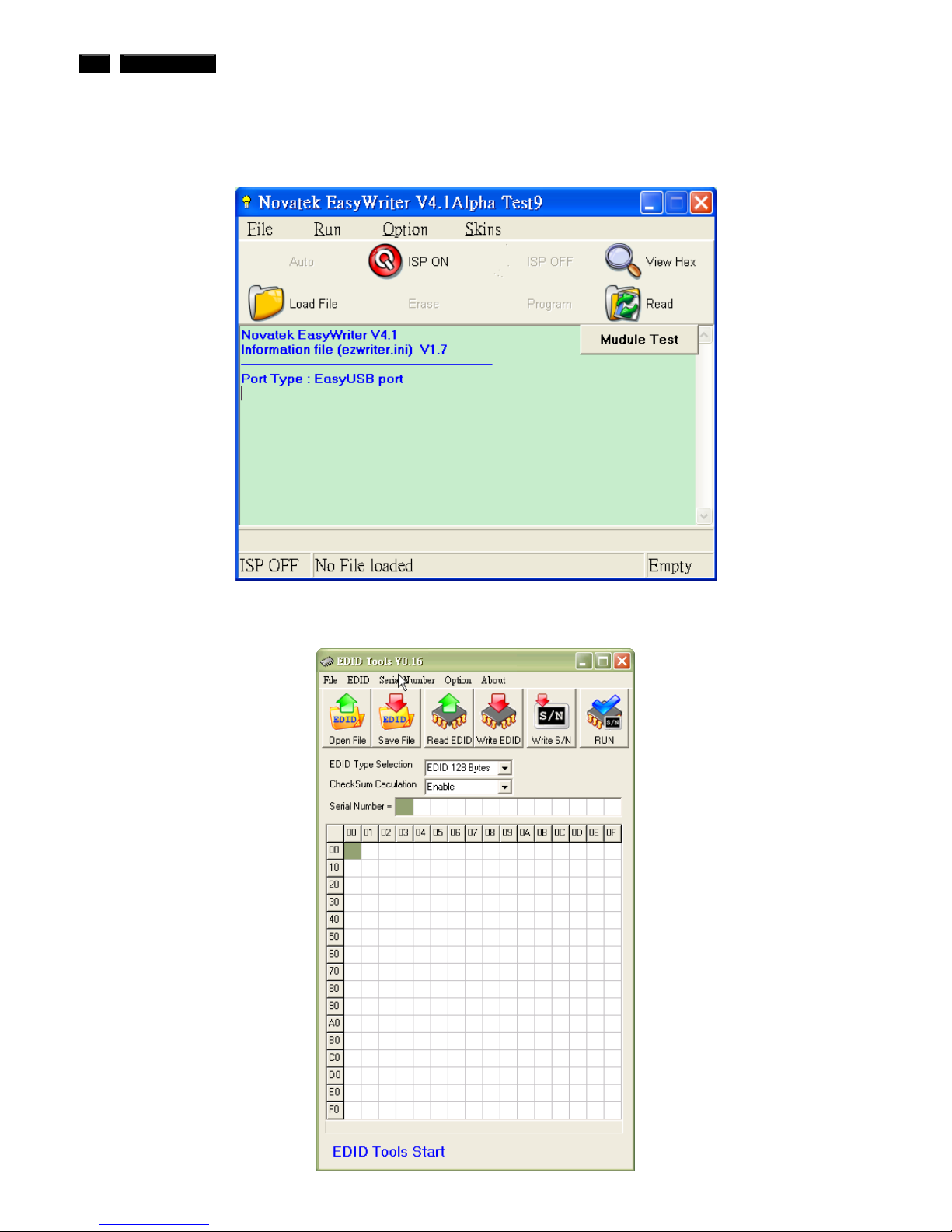
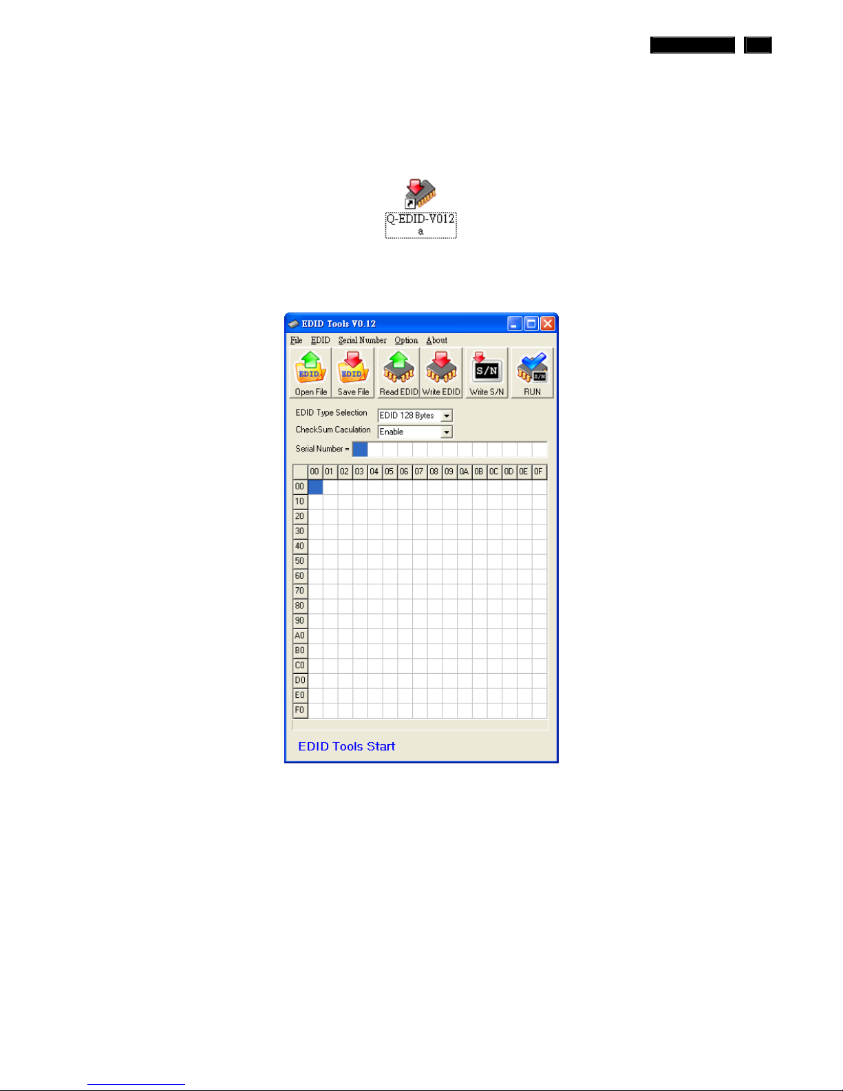
6. Setup the Philips-IMS EDID Tools program
Step 1: Open Q-EDID Software into your folder as shown in Fig.3. and Fig.4.
Fig.3
Fig.4
190C1 LCD 25
26 190C1 LCD
DDC Instructions
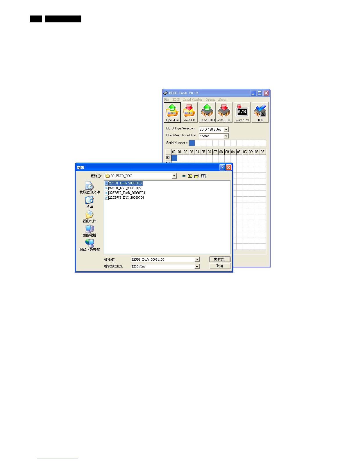
Step 2: Press “Open File” then choose
LCD_Analog.ddc or LCD_DVI.ddc as shown in Fig. 5 .
Fig.5
190C1 LCD 27
DDC Instructions
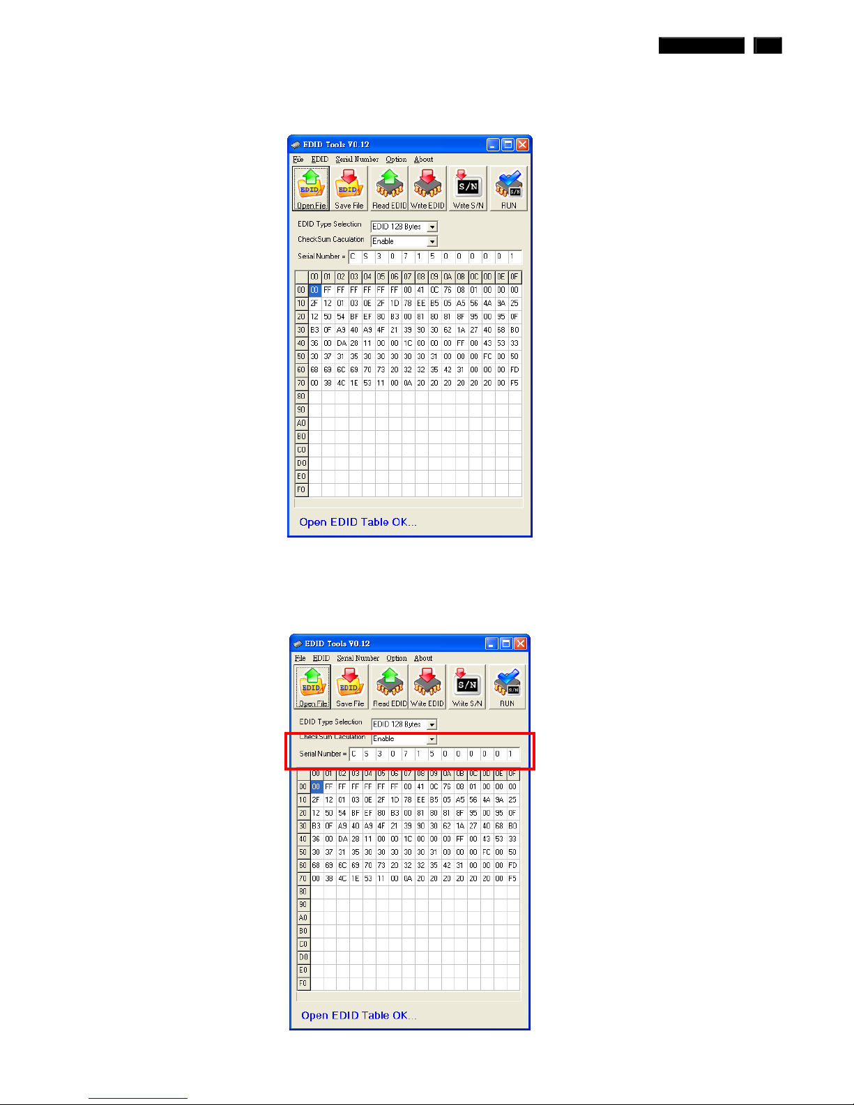
Step 3 : Load DDC file success as shown in Fig. 6 .
Fig.6
Step 4 : update Serial number and press enter to correct S/N number
shown as Fig.7 .
Fig.7
28 190C1 LCD
DDC Instructions
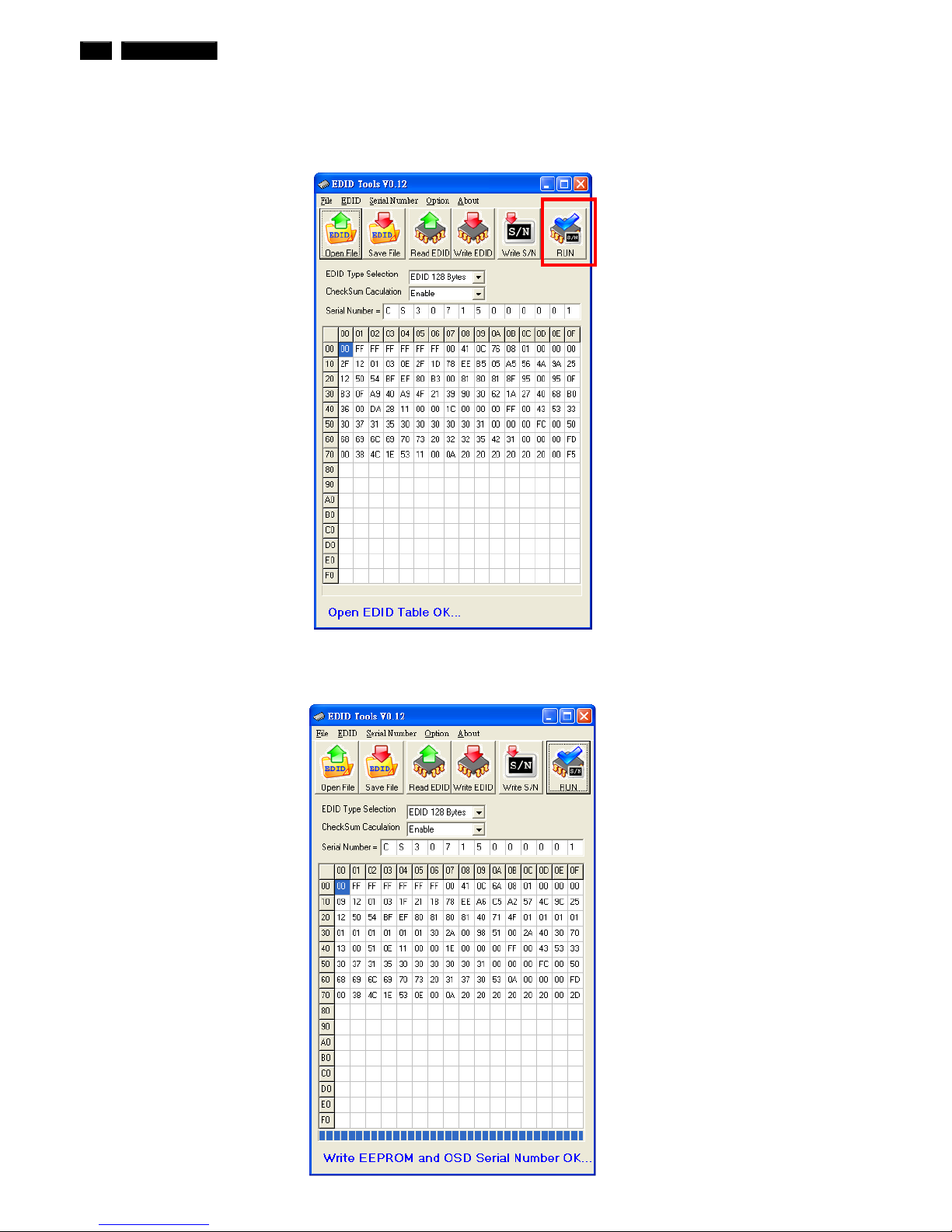
Step 5 : Press “RUN” to write EDID and serial number shown as Fig.8 .
Fig.8
Step 6 : EDID and serial number update success shown as Fig.9
Fig.9
190C1 LCD 29
DDC Instructions
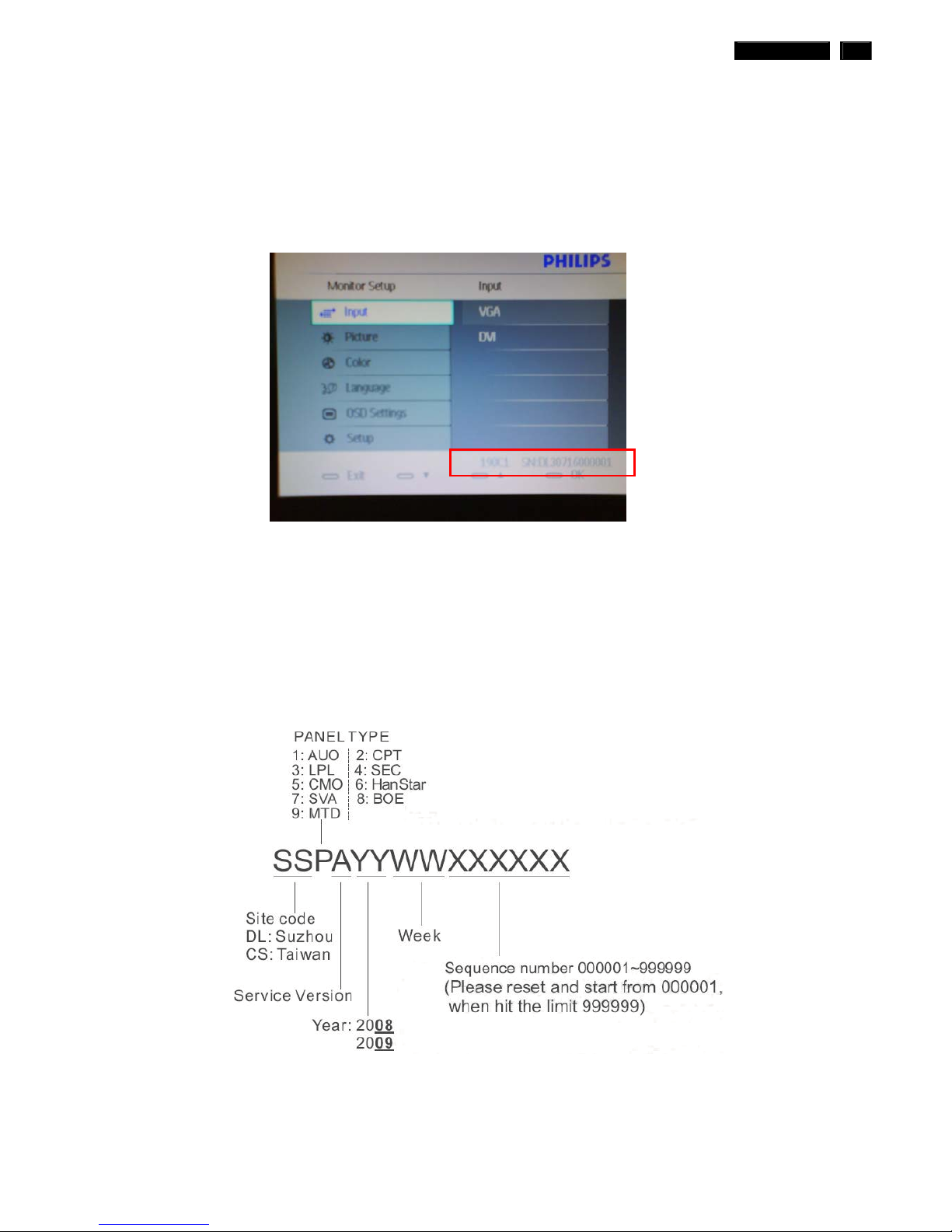
8. Press Monitor Menu Key to check OSD Serial number is the same as PI-EDID
write data as shown in Fig.10
Note: If not the same, please rewrite EDID S/N again.
Fig.14
9. Turn off the monitor, exit the factory mode.
Serial Number Definition
 Loading...