

Philips 190B7, 190B7CS/00, 190B7CB/27, 190B7CB/00, 190B7CB/69 Service Manual
...
19” LCD Color Monitor 190B7
1
Service
Service
Service
Horizontal Frequency
30- 83KHz
TABLE OF CONTENTS
Description Page Description Page
SAFETY NOTICE
ANY PERSON ATTEMPTING TO SERVICE THIS CHASSIS MUST FAMILIARIZE HIMSELF WITH THE CHASSIS
AND BE AWARE OF THE NECESSARY SAFETY PRECAUTIONS TO BE USED WHEN SERVICING
ELECTRONIC EQUIPMENT CONTAINING HIGH VOLTAGES.
CAUTION: USE A SEPARATE ISOLATION TRANSFOMER FOR THIS UNIT WHEN SERVICING
Table Of Contents...........…......................................………….1
Revision List.....................................................…………….2
Important Safety Notice……………….................................3
1. Monitor Specifications……….....................................…..4
2. LCD Monitor Description………..………..........................5
3. Operation instructions……………...........................…....6
3.1General Instructions………………………..…..…………6
3.2 Control buttons…………..……………………………………6
3.3 Adjusting the Picture…….......................................…..7
3.4 Connecting to the PC …….............…….…...........……....11
4. Input/Output Specification...........................…………….12
4.1 Input Signal Connector................................…………..12
4.2 Factory Preset Display Modes......................……..........13
4.3 Pixel Defect Policy………………………………..…………14
5. Block Diagram……………………………….……................16
5.1 Monitor Exploded View……………….…………...............16
5.2 Software Flow Chart...................................………….....17
5.3 Electrical Block Diagram..................……………….........19
6. Schematic Diagram…….................................……….........21
6.1 Main Board…….……………….……………………………21
6.2 Power Board…………………………………..…………………26
6.3 Audio Board…….…………………………..…………………28
7. PCB Layout.....……...............................……………………..29
7.1 Main Board.....……................................……..…………......29
7.2 Power Board.…….........................…..…………….............32
7.3 Audio Board………..…………………………..…………………35
7.4 Key Board………...………………………………………………35
7.5 USB Board…….………………………………………………35
8. Wiring Diagram……………………………………………….…..36.
9. Mechanical Instructions.....…….............……………..…..........37
10.Trouble shooting…..…………………………………...……..45
11. Repair Flow Chart…….…….……………………………………47
12. ISP Instructions..…..........................………………..............52
13. DDC Instructions……......…….............………….................58
14. White Balance, Luminance Adjustment……….................72
15. Spare Parts List...……..................……………........................73
16. Different Parts List...……….....……………........................86
17. General Product Specification……………………………….105
GB
3138 106 10506
19” LCD Color Monitor 190B7
2
Revision List
Version Release Date Revision History
A00 April.10, 2006 Initial release, Draft Version
A01 Jun.15, 2006
Add CTV Model 190B7CB/27,
190B7CG/00, 190B7CS/27 in Item 16
A02 Sep.11, 2006
Add CTV Model 190B7CB/00,
190B7CB/69, 190B7CB/75,
190B7CB/93, 190B7CS/69,
190B7CS/75, 190B7CS/96 in Item 16
A03 Sep.18, 2006
Make some Engineering Changes
in Item 15 and Item 16
A04 Oct.24, 2006 Add Service Kit in Page 73
A05 Nov.10, 2006 Revise Service Kit in Page 73
A06 Nov.29, 2006 Add DDC Instruction for OSD SN in Item 13
A07 Dec.05, 2006 Add OSD SN Kit in Page 73
A08 Jan.17, 2007 Add To Lock/Unlock OSD function in Page 7

19” LCD Color Monitor 190B7
3
Important Safety Notice
Proper service and repair is important to the safe, reliable operation of all Philips Company** Equipment. The
service procedures recommended by Philips and described in this service manual are effective methods of
performing service operations. Some of these service operations require the use of tools specially designed for the
purpose. The special tools should be used when and as recommended.
It is important to note that this manual contains various CAUTIONS and NOTICES which should be carefully read
in order to minimize the risk of personal injury to service personnel. The possibility exists that improper service
methods may damage the equipment. It is also important to understand that these CAUTIONS and NOTICES ARE
NOT EXHAUSTIVE. Philips could not possibly know, evaluate and advise the service trade of all conceivable ways
in which service might be done or of the possible hazardous consequences of each way. Consequently, Philips has
not undertaken any such broad evaluation. Accordingly, a servicer who uses a service procedure or tool which is
not recommended by Philips must first satisfy himself thoroughly that neither his safety nor the safe operation of
the equipment will be jeopardized by the service method selected.
* * Hereafter throughout this manual, Philips Company will be referred to as Philips.
WARNING
Use of substitute replacement parts, which do not have the same, specified safety characteristics may create
shock, fire,
or other hazards.
Under no circumstances should the original design be modified or altered without written permission from Philips.
Philips
assumes no liability, express or implied, arising out of any unauthorized modification of design.
Servicer assumes all liability.
FOR PRODUCTS CONTAINING LASER:
DANGER-Invisible laser radiation when open. AVOID DIRECT EXPOSURE TO BEAM.
CAUTION-Use of controls or adjustments or performance of procedures other than those specified herein may
result in hazardous radiation exposure.
CAUTION -The use of optical instruments with this product will increase eye hazard.
TO ENSURE THE CONTINUED RELIABILITY OF THIS PRODUCT, USE ONLY ORIGINAL MANUFACTURER'S
REPLACEMENT PARTS, WHICH ARE LISTED WITH THEIR PART NUMBERS IN THE PARTS LIST SECTION
OF THIS SERVICE MANUAL.
Take care during handling the LCD module with backlight unit
-Must mount the module using mounting holes arranged in four corners.
-Do not press on the panel, edge of the frame strongly or electric shock as this will result in damage to the screen.
-Do not scratch or press on the panel with any sharp objects, such as pencil or pen as this may result in damage to
the
panel.
-Protect the module from the ESD as it may damage the electronic circuit (C-MOS).
-Make certain that treatment person’s body is grounded through wristband.
-Do not leave the module in high temperature and in areas of high humidity for a long time.
-Avoid contact with water as it may a short circuit within the module.
-If the surface of panel becomes dirty, please wipe it off with a soft material. (Cleaning with a dirty or rough cloth
may damage the panel.)

19” LCD Color Monitor 190B7
4
1. Monitor Specifications
Screen type Active matrix - TFT LCD
Panel Type LM190E03-TLBD
Size 19"
Pixel pitch 0.294mm(H) x 0.294mm(V)
Separate Sync
TTL level, input impedance 2.2k OHM terminate
Horizontal Frequency 30kHz – 83kHz
LCD Panel
Vertical refresh rate 56Hz - 76Hz
15pin D-SUB
Input Connector
24pin DVI
1280 x 1024 at 76Hz (analog input)
Maximum Resolution
1280 x 1024 at 76Hz (digital input)
Display Colors 16.2 M
Video dot rate 140 MHz
Recommended Resolution 1280 x 1024 at 60Hz (digital input)
Plug & Play VESA DDC2B
Power Consumption
Power on: < 40 W
Power off: < 1 W
Input Video Signal 0.7 Vp-p, input impedance, 75 ohm @DC
Tilt -5° ~ 25°
Active Viewing Area
Horizontal: 376.3mm;Vertical: 301.1 mm
Power Source
100-240 VAC, 50/60 Hz
Environmental
Considerations
Operating Temp: 5°C to 40°C
Storage Temp.: -20°C to 60°C
Relative Humidity: 20%-80%
Weight (Net) 6.14kg
Cabinet color
190B7CG: Light Gray
190B7CB: Black
190B7CS: Silver
19” LCD Color Monitor 190B7
5
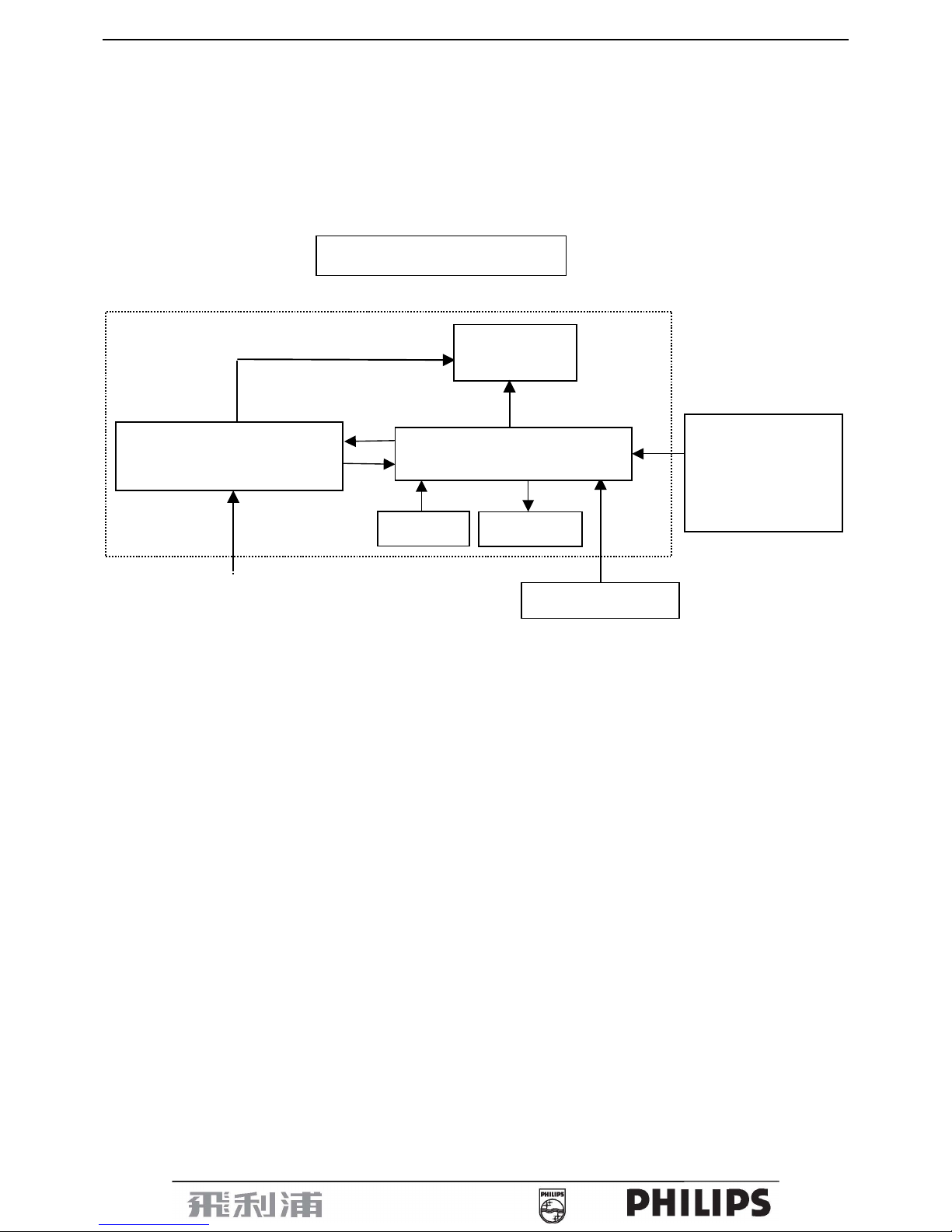
2. LCD Monitor Description
The LCD MONITOR will contain a main board, PWPC board, keypad board, which house the flat panel control
logic, brightness control logic and DDC.
The power board will provide AC to DC Inverter voltage to drive the backlight of panel and the main board chips
each voltage.
Video signal, DDC
Flat Panel and
CCFL backlight
Keyboard
RS232 Connector
For white balance
adjustment in factory
mode
CCFL Drive.
AC-IN
100-240V
Monitor Block Diagram
HOST Computer
A
udio Board
Main Board
PWPC board
(Included: adapter and inverter)
19” LCD Color Monitor 190B7
6
3. Operation instructions
3.1 General Instructions
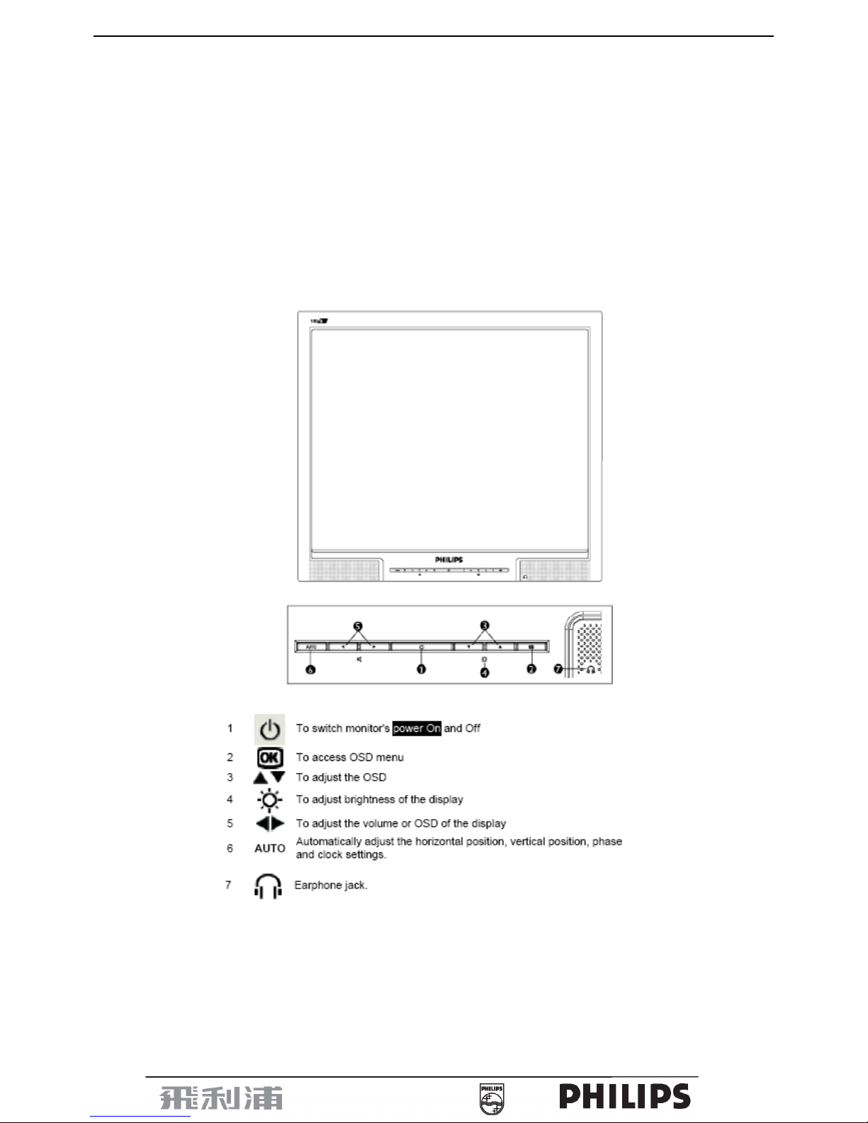
Press the power button to turn the monitor on or off. The other control buttons are located at front panel of the
monitor. By changing these settings, the picture can be adjusted to your personal preferences.
-
The power cord should be connected.
-
Connect the video cable from the monitor to the video card.
-
Press the power button to turn on the monitor, the power indicator will light up.
3.2 Control Buttons
Front View
19” LCD Color Monitor 190B7
7
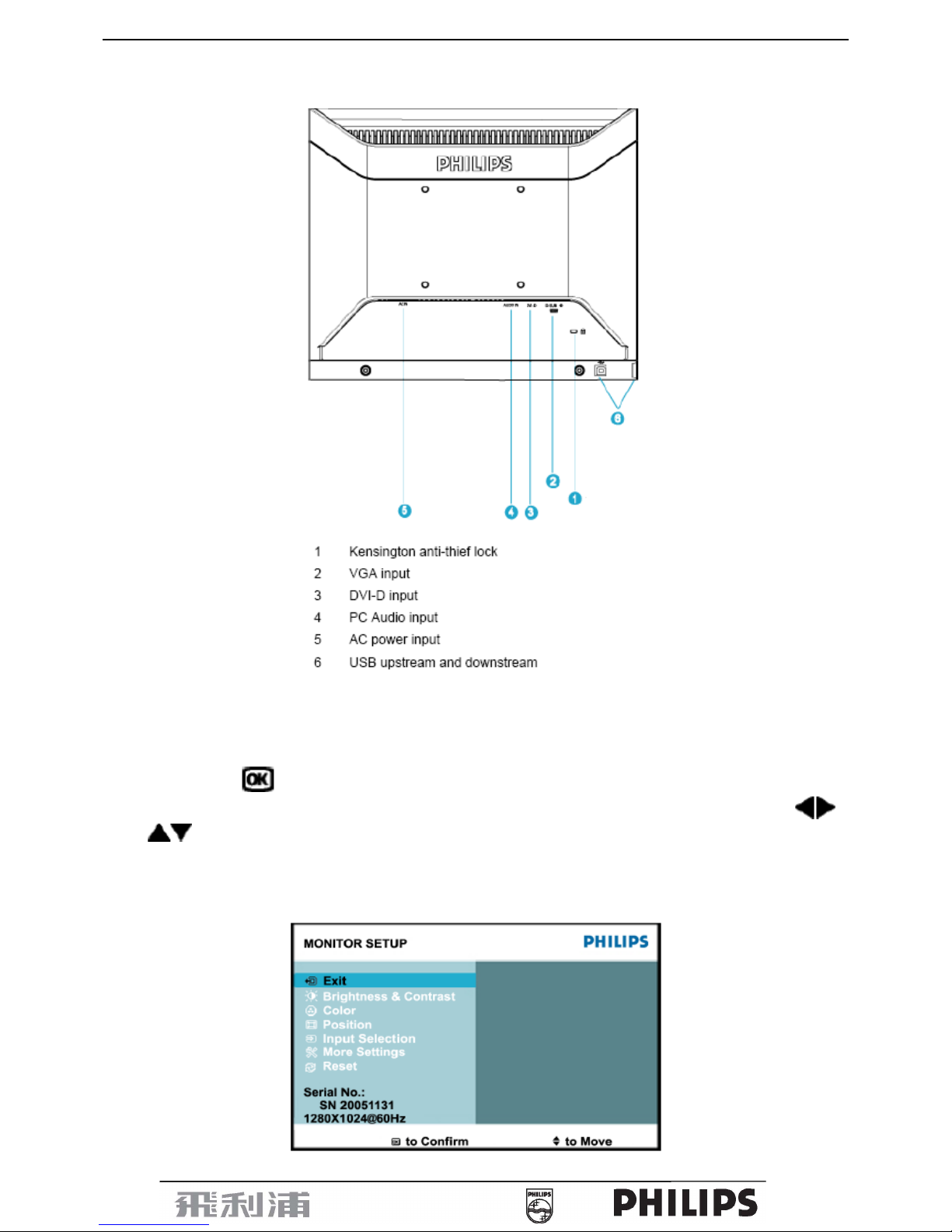
Rear View
3.3 Adjusting the Picture
This is a feather in all Philips LCD monitors. It allows an end user to adjust screen performance of the monitors
directly through an on-screen instruction window. The user interface provides user-friendliness and ease-of-use
when operating the monitor.
When you press the
button on the front control of your monitor, the On-Screen Display (OSD) main controls
window will pop up and you can then start making adjustments to your monitor’s various features. Use the
or the
keys to make your adjustments.
To Lock/Unlock OSD function (User Mode)
The OSD function can be locked by pressing “MENU” button for more than 10 seconds.
Locked OSD function can be released by pressing “MENU” button for more than 10 seconds again.
19” LCD Color Monitor 190B7
8
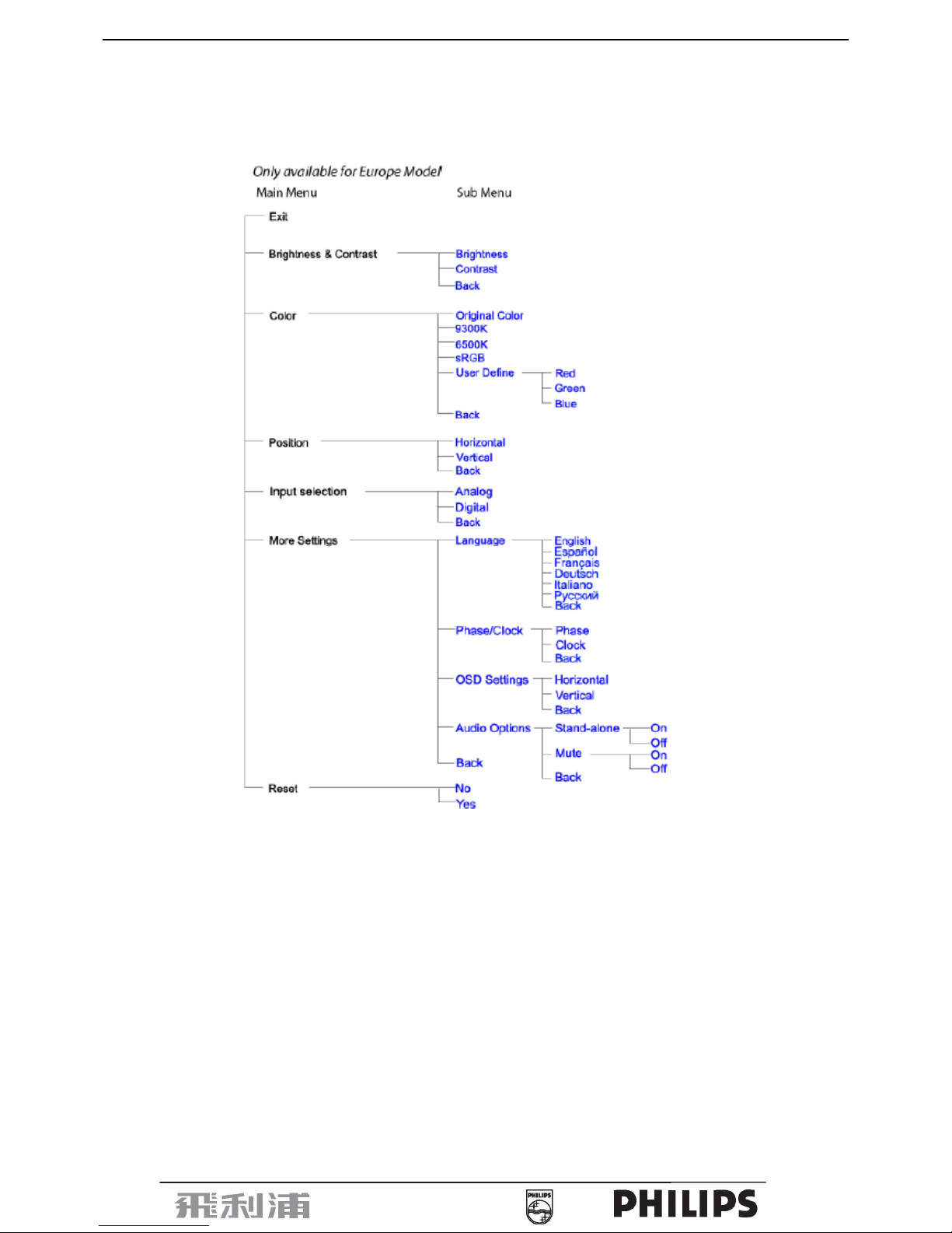
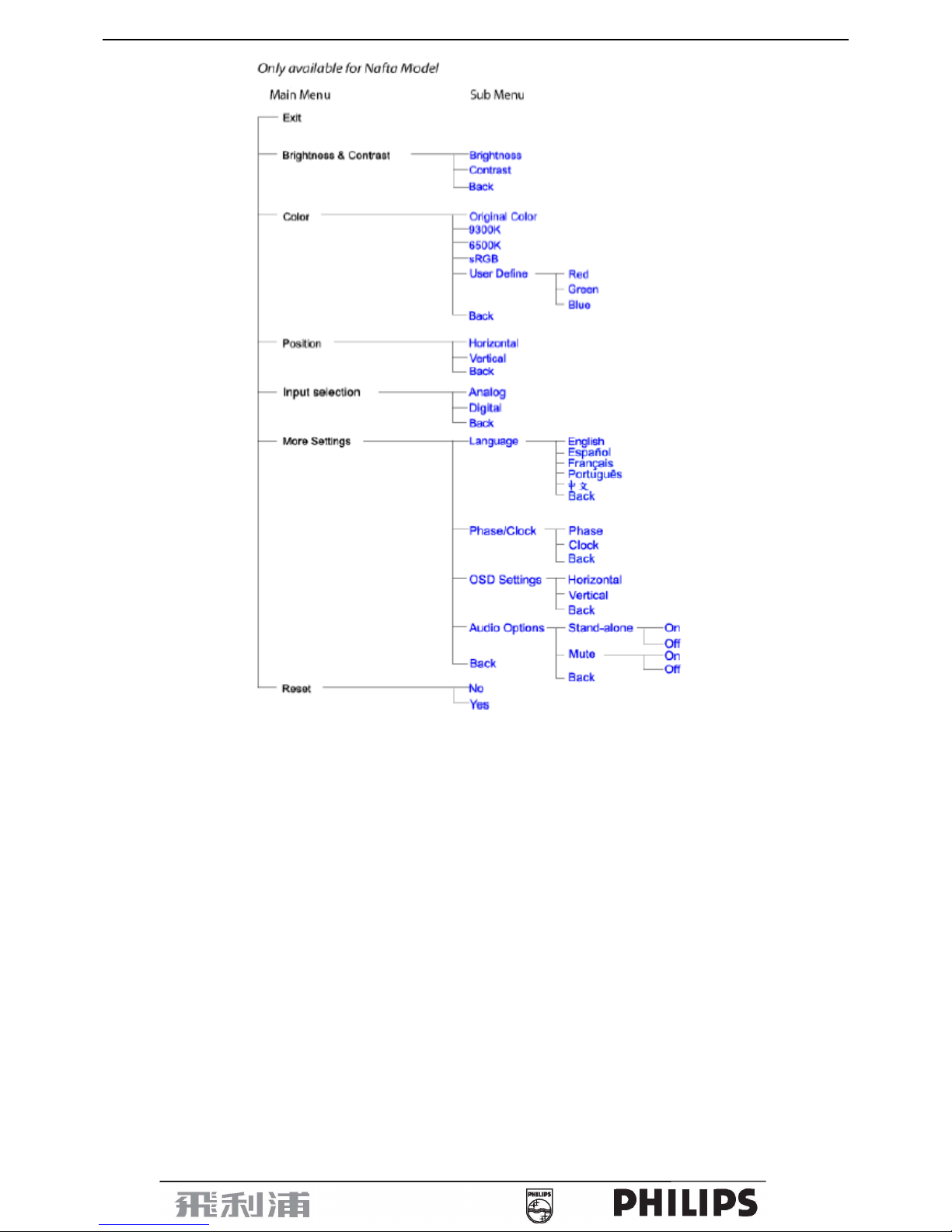
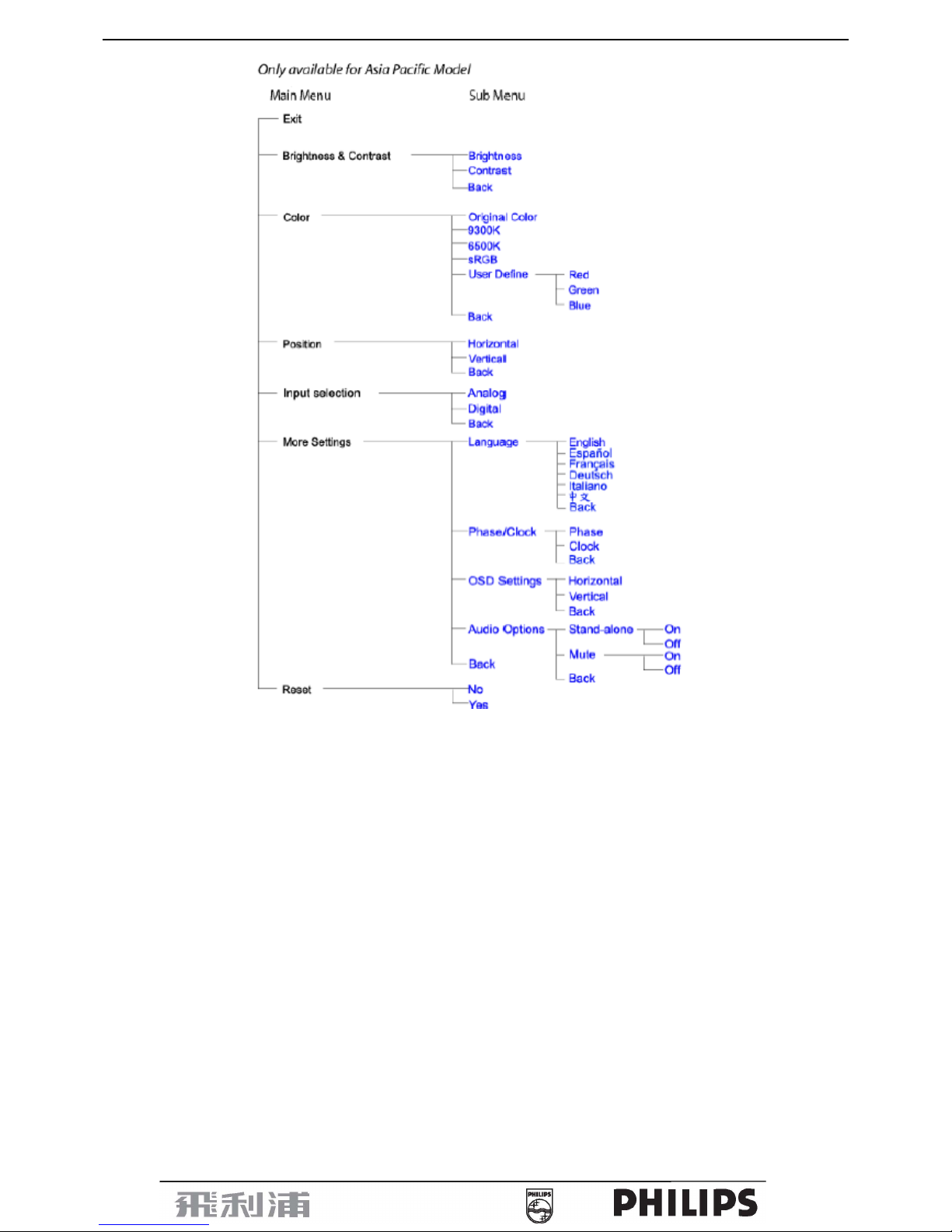
The OSD tree
Below is an overall view of the structure of the On-Screen Display. You can use this as a reference when you want to
work your way around the different adjustments later on.
19” LCD Color Monitor 190B7
9
19” LCD Color Monitor 190B7
10

19” LCD Color Monitor 190B7
11
3.4 Connecting to the PC
1) Connect the power cord to the back of the monitor firmly. (Philips has pre-connected) VGA cable for the first
installation.)
2) Connect to PC
(a) Turn off your computer and unplug its power cable.
(b) Connect the monitor signal cable to the video connector on the back of your computer.
(c) Plug the power cord of your computer and your monitor into a nearby outlet.
(d) Connect the PC audio cable to the audio connector on the back of your computer.
(e) USB plug
(1) Connect USB upstream port on monitor and the USB port on PC with a USB cable.
(2) The USB downstream port is now ready for any USB device to plug in.
(f) Turn on your computer and monitor. If the monitor displays an image, installation is complete.
19” LCD Color Monitor 190B7
12
4. Input/Output Specification
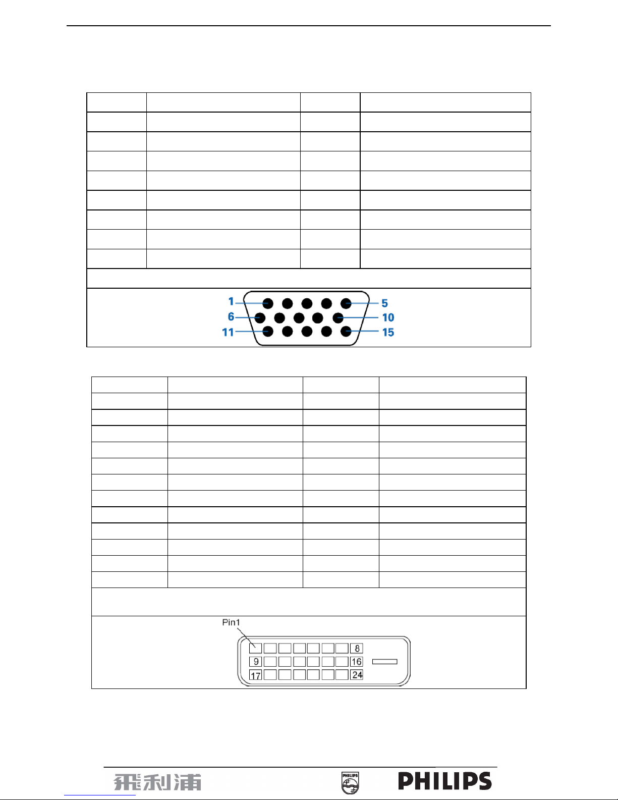
4.1 Input Signal Connector
4.1.1 D-SUB connector
Pin NO. Description Pin NO. Description
1. Red Video input 9. DDC +5V
2. Green Video input (SOG) 10. Logic GND
3. Blue Video input 11. Ground
4. Sense (GND) 12. Serial data line (SDA)
5. Cable Detect (GND) 13. H.sync/H + V.sync
6. Red Video Ground 14. V.Sync
7. Green Video Ground 15. Data Clock Line (SCL)
8. Blue Video Ground
VGA Connector layout
4.1.2 DVI connector
Pin No. Description Pin No. Description
1.
TMDS data 2-
13. No connect
2.
TMDS data 2+
14.
+5V Power
3. TMDS data 2/4 Shield 15. GND (for +5V)
4. No connect 16. Hot Plug Detect
5. No connect 17.
TMDS data 0-
6. DDC Clock 18.
TMDS data 0+
7. DDC Data 19. TMDS data 0/5 Shield
8. No Connect 20. No connect
9.
TMDS data 1-
21. No connect
10.
TMDS data 1+
22. TMDS Clock Shield
11. TMDS data 1/3 Shield 23. TMDS Clock +
12. No connect 24.
TMDS Clock -
Digital Connector

19” LCD Color Monitor 190B7
13
4.2 Factory Preset Display Modes
19” LCD Color Monitor 190B7
14
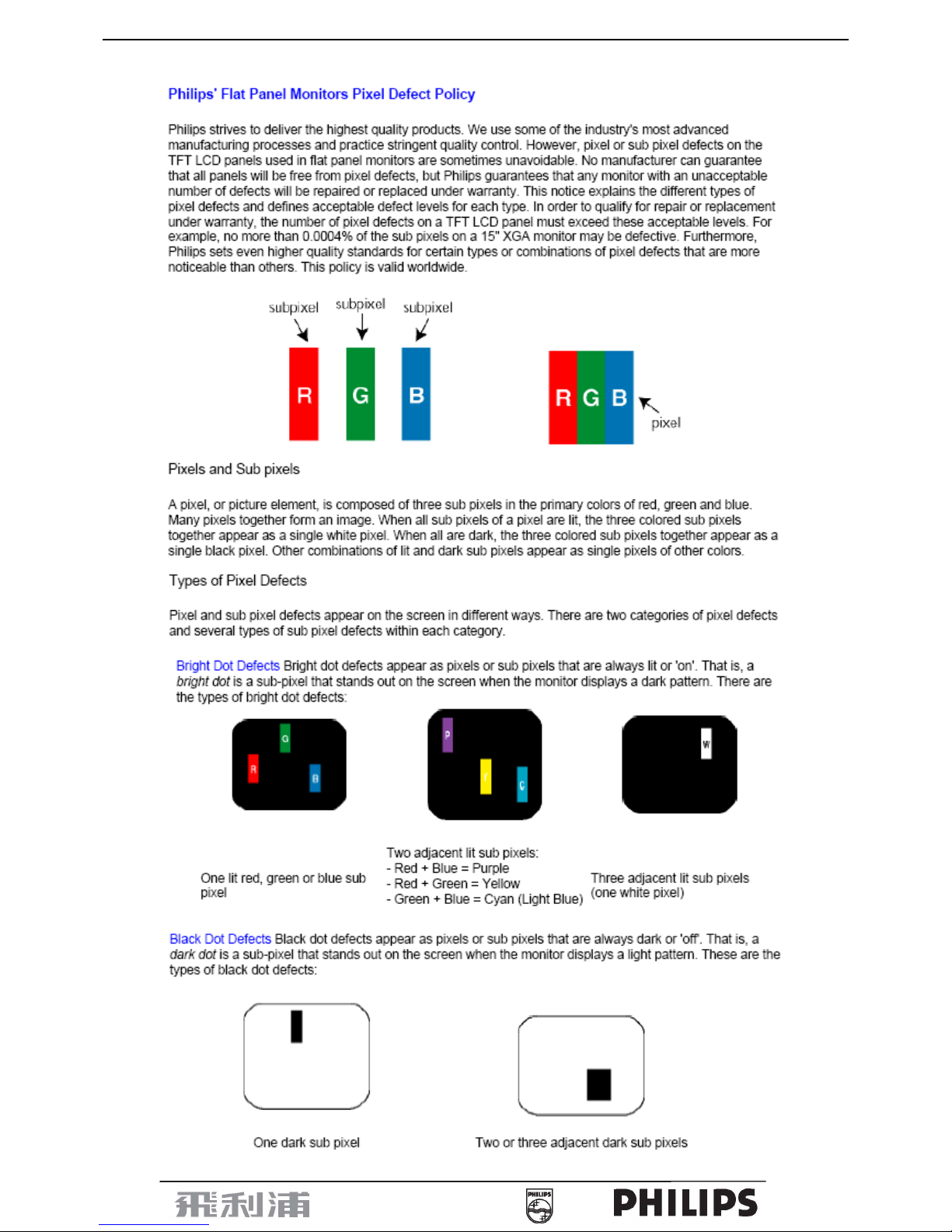
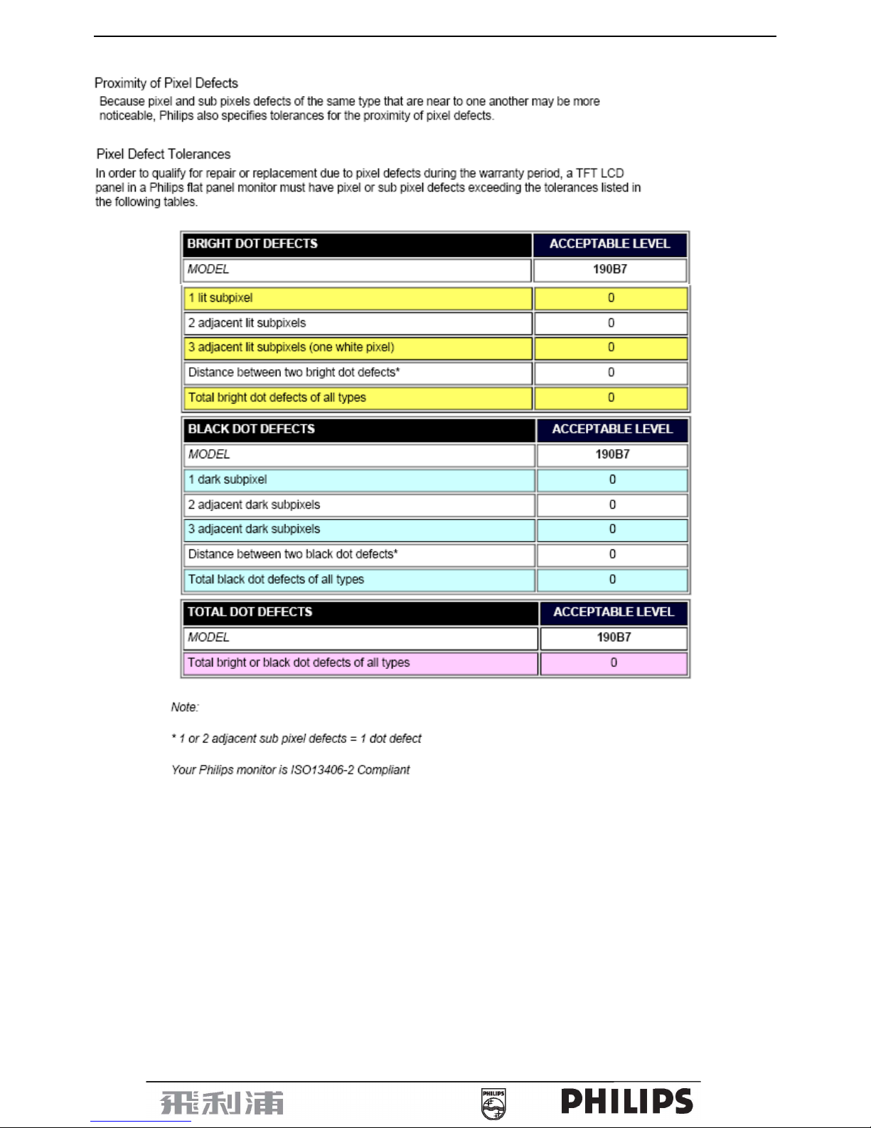
4.3 Pixel Defect Policy
19” LCD Color Monitor 190B7
15
19” LCD Color Monitor 190B7
16
5. Block Diagram
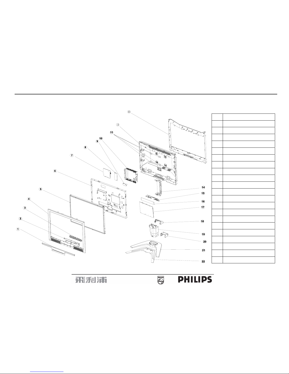
5.1 Monitor Exploded View
(1) BEZEL-DECO
(2) KEY BOARD
(3) CONTROL BUTTON
(4) BEZEL
(5) PANEL
(6) MAIN FRAME
(7) MAIN BOARD
(8) AUDIO BOARD
(9) USB BOARD
(10) SCALER SHIELDING
(11) BKT-VESA
(12) REAR COVER
(13) MID_COVER
(14) SHIELD-PWR
(15) POWER BRACKET
(16) MYLAR
(17) POWER BOARD
(18) HEING COVER BACK
(19) HINGE ASS'Y
(20) HINGE COVER FRONT
(21) BASE
(22) BASE BRACKET
19” LCD Color Monitor 190B7
17
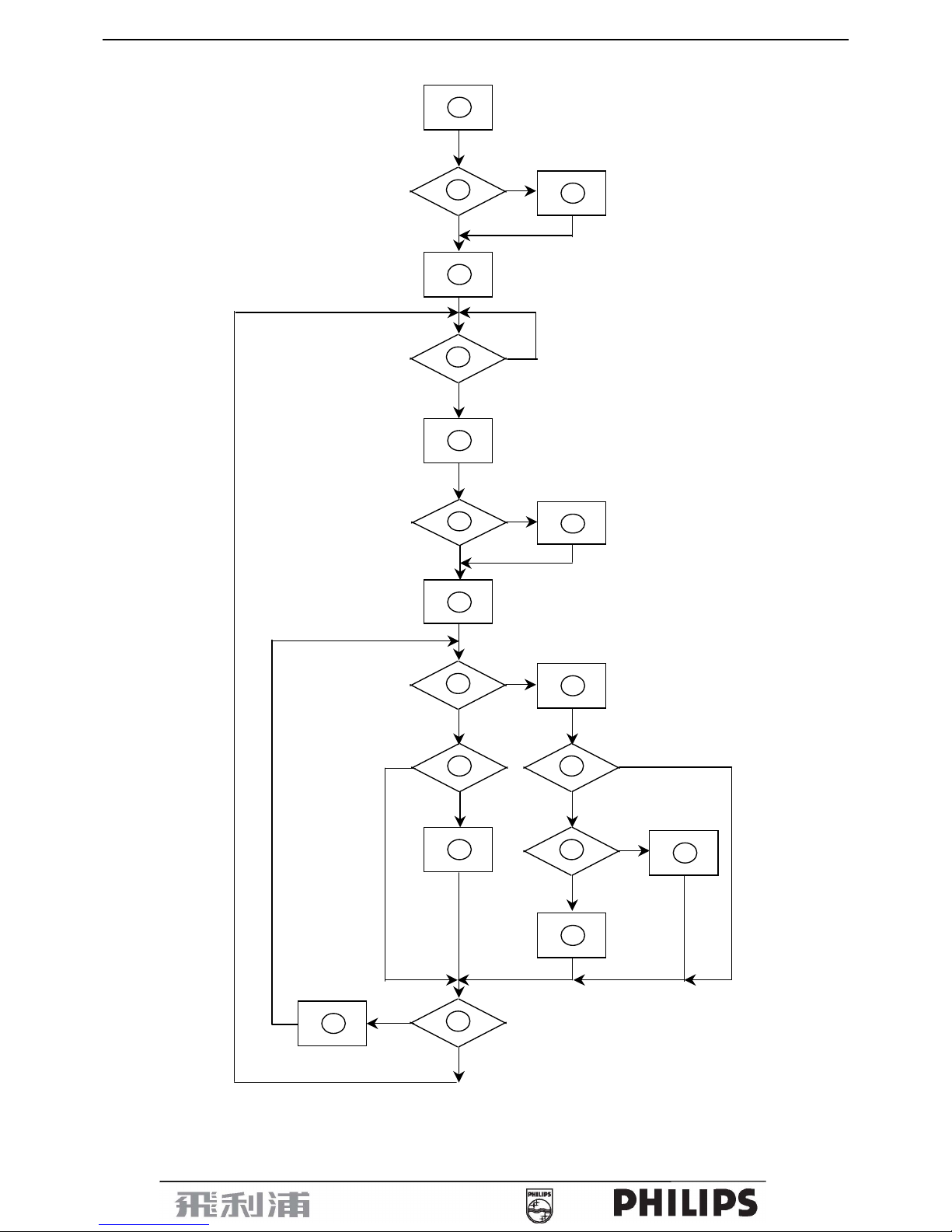
5.2 Software Flow Chart
1
2
N
Y
5
Y
N
10
Y
N
12
Y
N
7
Y
N
6
4
3
8
9
14
11
13
Y
N
15
Y
N
16
17
19
Y
N
18

19” LCD Color Monitor 190B7
18
1) MCU Initializes.
2) Is the EEprom blank?
3) Program the EEprom by default values.
4) Get the PWM value of brightness from EEprom.
5) Is the power key pressed?
6) Clear all global flags.
7) Are the AUTO and SELECT keys pressed?
8) Enter factory mode.
9) Save the power key status into EEprom.
Turn on the LED and set it to green color. Scalar
initializes.
10) In standby mode?
11) Update the lifetime of back light.
12) Check the analog port, are there any signals coming?
13) Does the scalar send out an interrupt request?
14) Wake up the scalar.
15) Are there any signals coming from analog port?
16) Display "No connection Check Signal Cable" message. And go into standby mode after the message
disappears.
17) Program the scalar to be able to show the coming mode.
18) Process the OSD display.
19) Read the keyboard. Is the power key pressed?
19” LCD Color Monitor 190B7
19
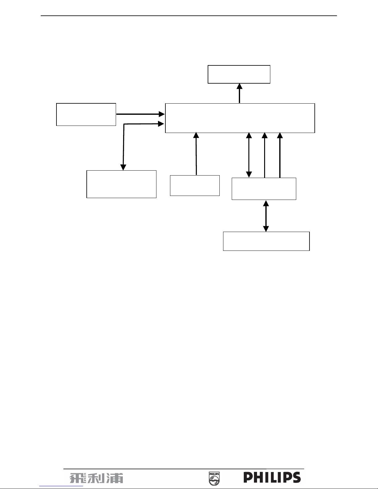
5.3 Electrical Block Diagram
5.3.1 Main Board
EEPROM
AT24C16AN-10SU-2.7
(
U403)
Panel Interface
NT68663MEFG
(Include MCU, ADC, OSD)
D-Sub Connector
(CN405)
EEPROM M24C02-WMN6TP
(
U405)
SDA
SCL
RXD
TXD
RGB
H-SYNC
V-SYNC
DB15_SDA
DB15_SCL
Crystal 12MHz
Keypad Interface
(CN403)

19” LCD Color Monitor 190B7
20
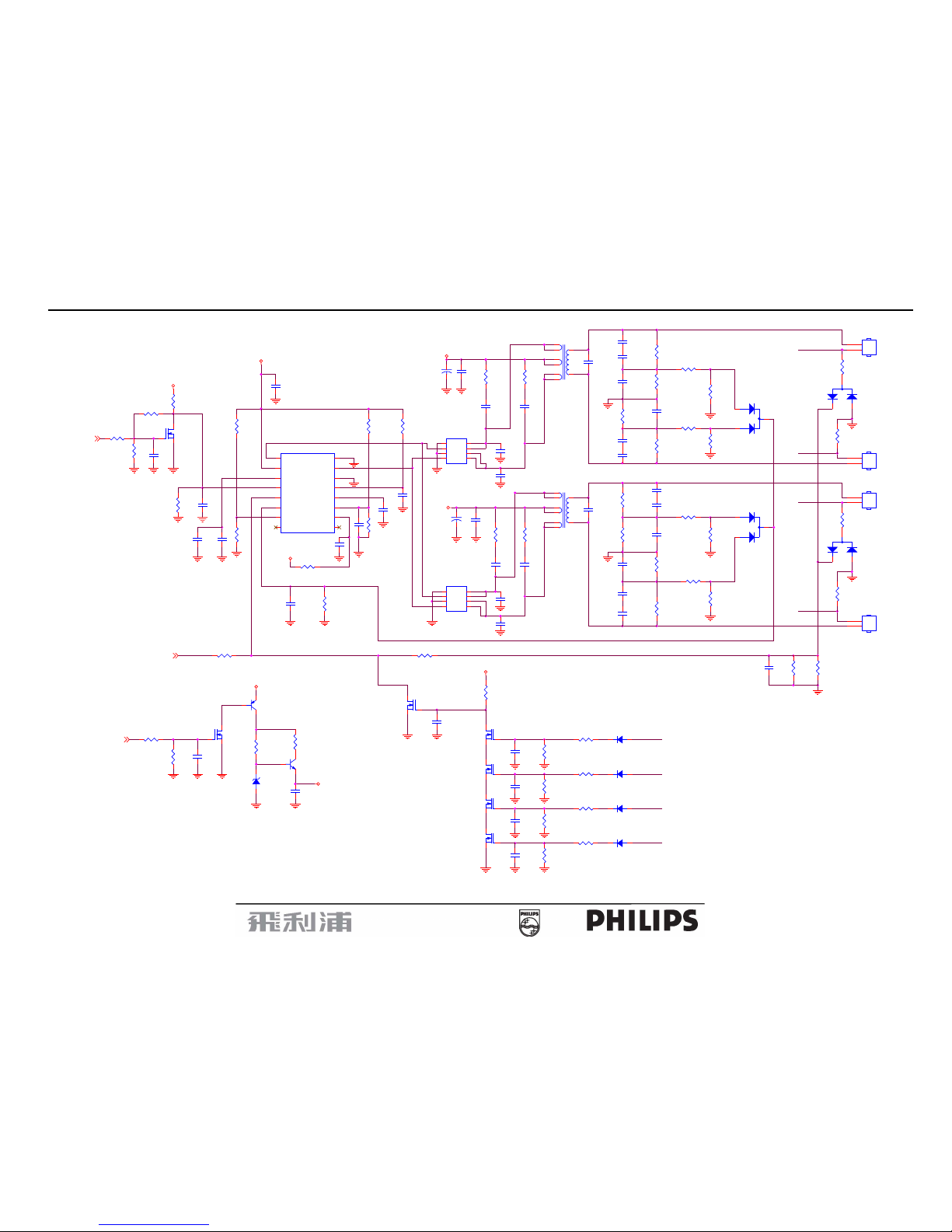
5.3.2 Inverter/Power Board
19” LCD Color Monitor 190B7
21
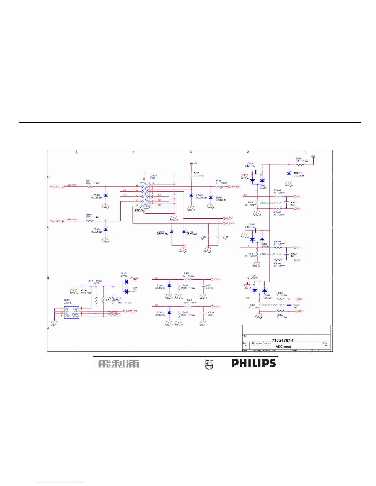
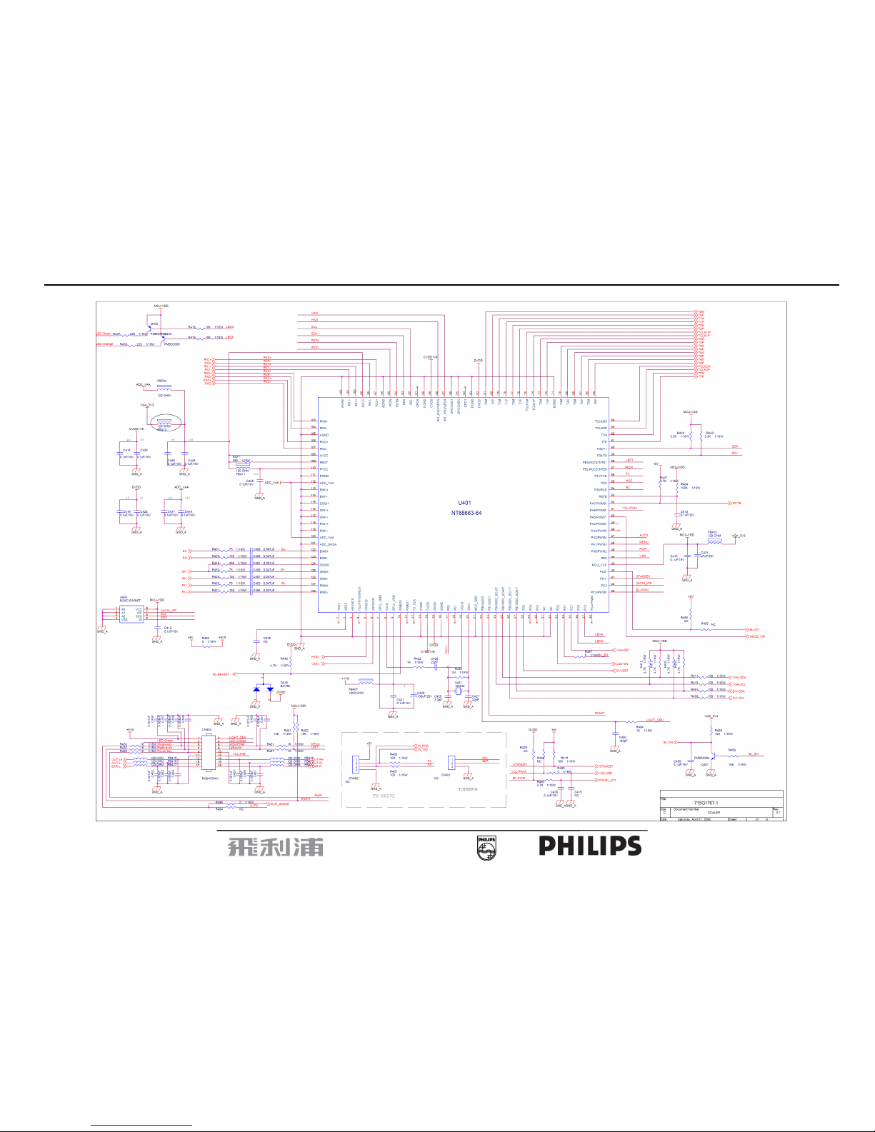
6. Schematic Diagram
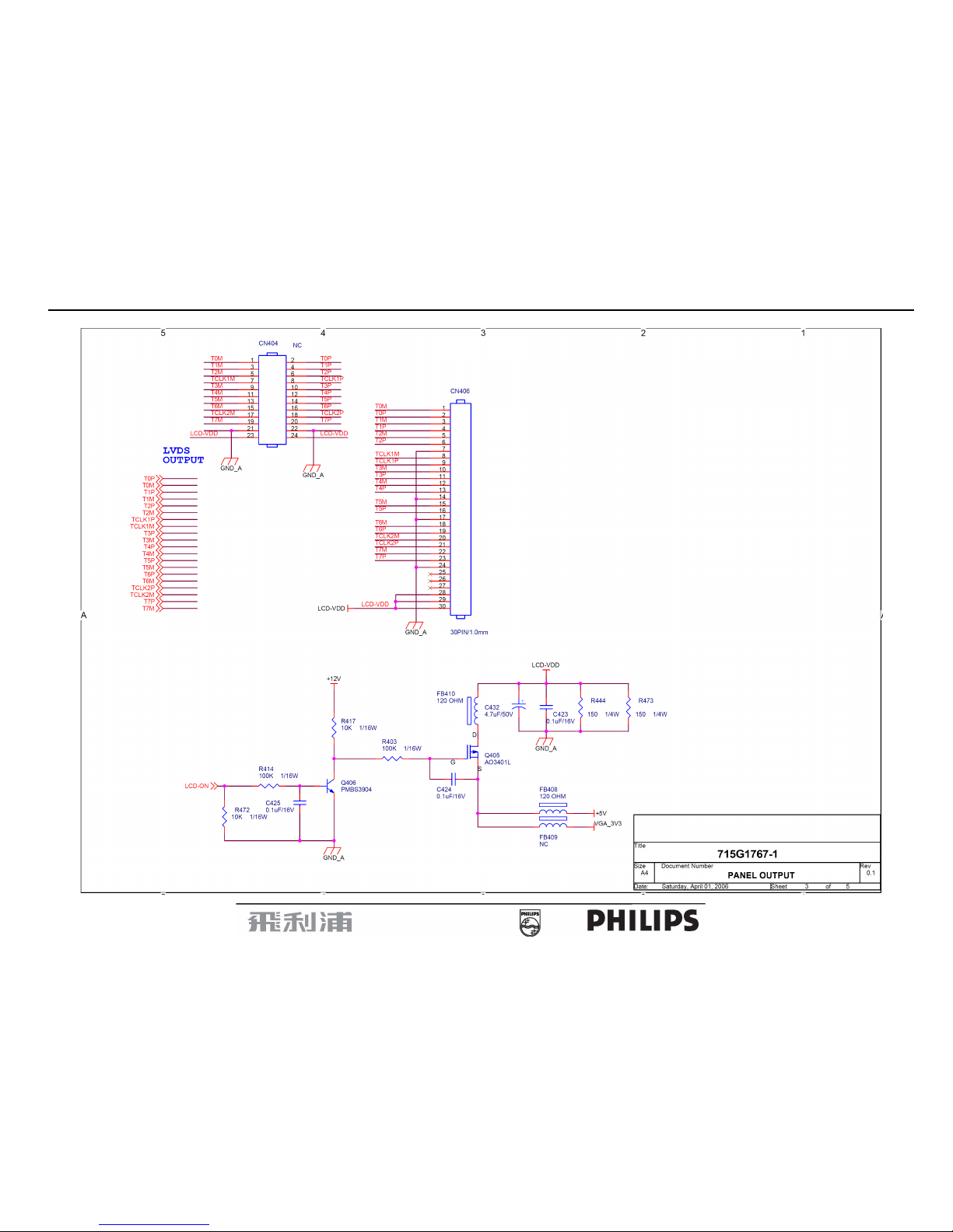
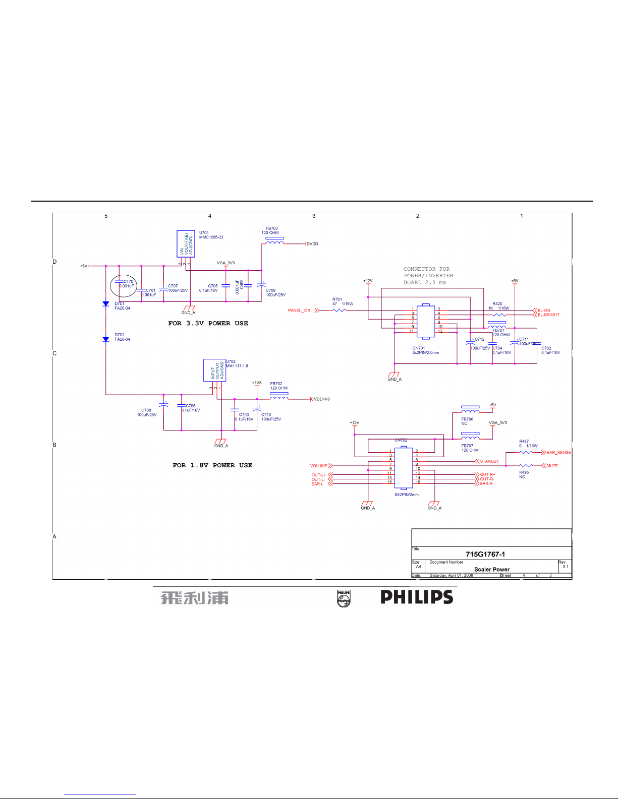
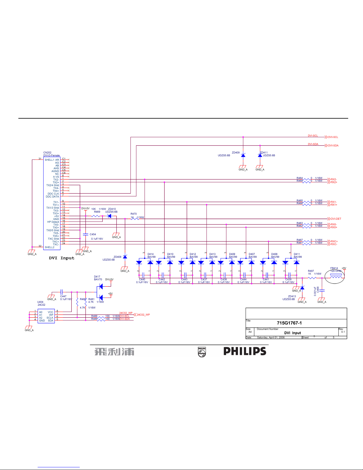
6.1 Main Board
715G1767-1
19” LCD Color Monitor 190B7
22
19” LCD Color Monitor 190B7
23
19” LCD Color Monitor 190B7
24
19” LCD Color Monitor 190B7
25
19” LCD Color Monitor 190B7
26
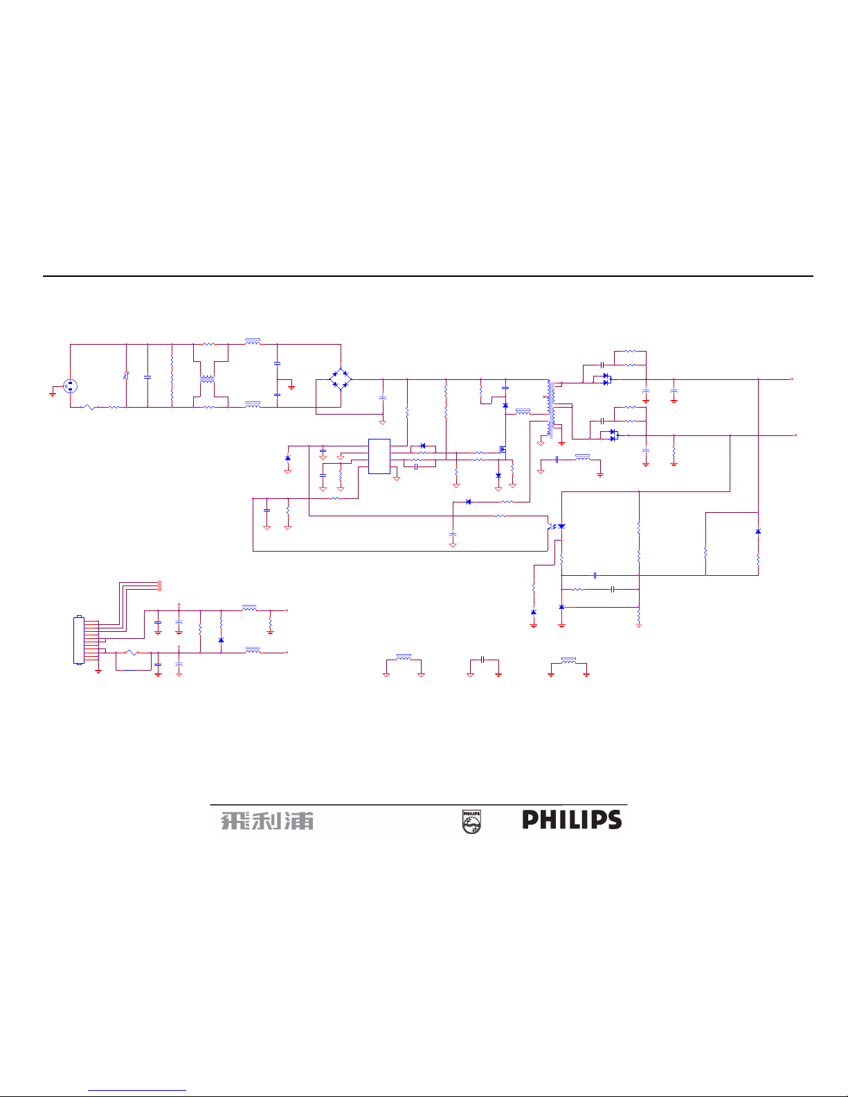
6.2 Power Board
715G1813-1
N
L903
C8B-R6H
1 2
R955
22K _NC
L
R953
1K 1/4W_NC
1 2
C915
0.012uF/25V
R917 33K
C913
0.1uF
12
R915 10
R927
4.7K_1206
12
-
+
BD901
U4KB80R
2
1
3
4
5VA
+
C927
68u/25V
R946
110K_1%
1 2
+12VCC
FB905
BEAD
C920
0.001uF/1KV
12
R910
1.5M/R1206
C903
0.001uF/250V
1 2
D918
1N4148
R944
9.1K/0805_1%
1 2
Lie down
C942
4.7nF/25V_NC
D931
MBRF10H100CT-45
NR901
SCK084
D926
RGP10D
12
TEA1532
IC901
TEA1532
4
128
5
36
7
FB901
BEAD
C914
1uF
12
D901
BYT42J
R932
2R2_1206
1 2
+
C933
1000uF/25V
+
C952
220u/25V
C901
0.001uF/250V
12
O
T901
POWER X'FMR
4
6
2
1
5
9
7
8
11
12
10
J912
12
R912
1M
1 2
R951
3.3K _NC
1 2
FB902
BEAD
C935
3.3nF/500V_NC
12
R920
0.2R/1W
R902
680K
1 2
C917
0.33uF/25V
+12VCC
VAR901
varistor_NC
R935
2R2_1206_NC
1 2
C900
0.001uF/250V
12
CN951
HARNESS 12P-12P 120mm
1
2
3
4
5
6
7
8
9
10
11
12
R904
1.5M/R1206
+
C907
100uF/450V
R926 0R
R942
27K _NC
12
R901
680K
1 2
+
C956
220u/16V
IC902
TCET1103
12
43
IC941
KIA431A
L951
0.8uH
1 2
C912
0.0022uF/400V
12
+12V
CN901
AC SOCKET
1 2
3
C955
0.1uF/25V
L955
0.8uH
1 2
S901
spotgap_NC
R945
9.1K_1%
1 2
R907
15K/R1206
R936
2R2_1206_NC
1 2
R905
100K/1W
L901
7mH
14
23
+5V
R941
220
BRIGHTNESS
+
C936
2200uF/16V
C951
0.1uF/25V
R914
1K24_1%
R900
680K
1 2
C941
0.0056uF
5VA
R952
10
1 2
ZD949
RLZ12B_NC
1 2
R916 1.5K
12
BL_CTL
D905
P4KE_NC
D919
RGP10D
12
+
C932
1000uF/25V
R937
1.8K_1/8W
1 2
F902
FUSE_5A/250V_NC
R949
100 1/10W_NC
1 2
C908
0.47uF/275V
12
PANEL_ID
L902
C8B-R6H
1 2
R918 150R
12
R931
2R2_1206
1 2
FB903
BEAD
S902
spotgap_NC
ZD975
RLZ5.1B
1 2
ZD951
P6KE8.2A
C931
3.3nF/500V
12
Q901
STP7NK80ZFP
1
23
F901
FUSE 3.15A 250V
1 21 2
D935
STPS10L45CFP
R954
10 1/10W
R943
5.1K 1/10W
1 2
R923 8K66_1%
12
5
19” LCD Color Monitor 190B7
27
R887
100K 1/10W
12
C831
0.33uF
12
R812
620K 1/10W
12
Q841
AM9945N
1
2
3
4 5
6
7
8
S1
G1
S2
G2 D2
D2
D1
D1
D885
IN4148
C825
5PF/NC
1 2
Q871
2N7002
1
32
C812
0.1uF
12
Q886
2N7002
1
32
OP2
C823
0.001uF
1 2
C807
5pF/3KV
12
R843
10R
12
R872
10K/NC
1 2
D831
BAV99
3
1
2
R822
10R
12
D853
BAV70/SOT23B
3
1
2
R815
30K
R859
6.2M 1/2W
12
Q885
2N7002
1
32
Isen
C826
0.01uF/NC
R823
10R
12
R884
1K 1/10W
12
R871
10K 1/2W
12
OP3
Q880
2N7002
1
32
R839
6.2M 1/2W
12
R873
2K 1/10W
C887
0.01uF
Q873
PDTA144EU
3 1
2
R824
7.5K_1%_NC
1 2
VDD
OP2
C819
0.01uF/25V
12
R830
10K_1%_NC
12
D881
IN4148
OP4
C846
1uF
12
C844
5PF/NC
1 2
CN853
CONN
1
2
C805
5pF/3KV_NC
12
C842
0.001uF
1 2
VDD
R857
7.5K_NC
C858
390pF
C813
560pF
C832
0.1uF
12
C810
5pF/3KV_NC
12
C821
1uF
12
Q801
2N7002
1
32
Q874
2N3904
32
1
R804
10K 1/10W
12
D851
BAV99
3
1
2
PANEL_ID
OP1
C809
5pF/3KV_NC
12
C845
5PF/NC
1 2
D883
IN4148
C808
5pF/3KV
12
R855
10K_1%
ZD874
RLZ5.6B
1 2
OP4
Isen
C883
0.01uF
R861
100K_1%
12
C841
1uF
12
R866
100K/NC
12
+12V
R886
1K 1/10W
12
CN831
CONN
1
2
R883
100K 1/10W
12
C865
33nF
12
R835
10K_1%
1 2
C806
10pF/6KV
12
R819
1M
CN833
CONN
1
2
C860
220pF
12
CN851
CONN
1
2
C811
1uF
12
PT802
24:24:2400
7
1
3
85
6
2
4
R807
10K 1/10W
12
C840
470uF/25V
VDD
C820
470uF/25V
C822
0.001uF
1 2
PT801
24:24:2400
7
1
3
85
6
2
4
OP1
R833
1.2K
R801
10K
12
R854
6.2M_NC
12
+12V
R856
10K_1%
12
R880
10K 1/10W
12
R831
1K
R851
1K
R825
7.5K_1%
1 2
R806
100K/NC
1 2
C871
0.1uF_NC
C824
5PF/NC
1 2
C830
1000pF/NC
R834
6.2M 1/2W _NC
12
BL_CTL
OP3
R836
10K_1%
12
R874
330 1/10W
1 2
R803
10K/NC
12
C843
0.001uF
1 2
+12V
PANEL_ID
R802
10K/NC
1 2
C885
0.01uF
R850
10K_1%_NC
12
R882
1K 1/10W
12
R888
1K 1/10W
12
R853
1.2K
R885
100K 1/10W
12
Q821
AM9945N
1
2
3
4 5
6
7
8
S1
G1
S2
G2 D2
D2
D1
D1
R829
0 1/10W
C803
5pF/3KV
12
VDD
R865
232
C838
1000pF
Q883
2N7002
1
32
C801
10pF/6KV
12
R837
7.5K_1%
12
C847
0.022uF/25V
D887
IN4148
C802
5pF/3KV
12
U811
OZ9938GN
1
2
3
4
5
6
7
8 9
10
11
12
13
14
15
16
DRV1
VDDA
TIMER
DIM
ISEN
VSEN
OVPT
NC1 NC2
ENA
LCT
SSTCMP
CT
GNDA
DRV2
PGND
C874
1uF
12
BRIGHTNESS
D833
BAV70/SOT23B
3
1
2
R849
0 1/10W
1 2
C880
0.1uF/25V
C861
1000pF
12
VDD
R881
100K 1/10W
12
R842
10R
12
R816
20K
C804
5pF/3KV_NC
12
R863
33K 1/4W
12
R813
33K_1%
R811
3M3
12
C881
0.01uF
Q881
2N7002
1
32

19” LCD Color Monitor 190B7
28
6.3 Audio Board
715G1763-1
19” LCD Color Monitor 190B7
29
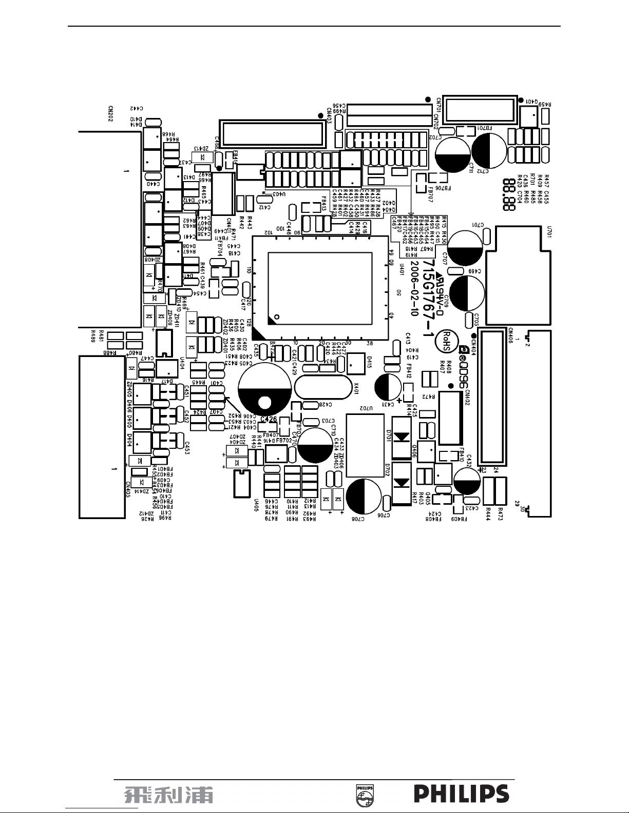
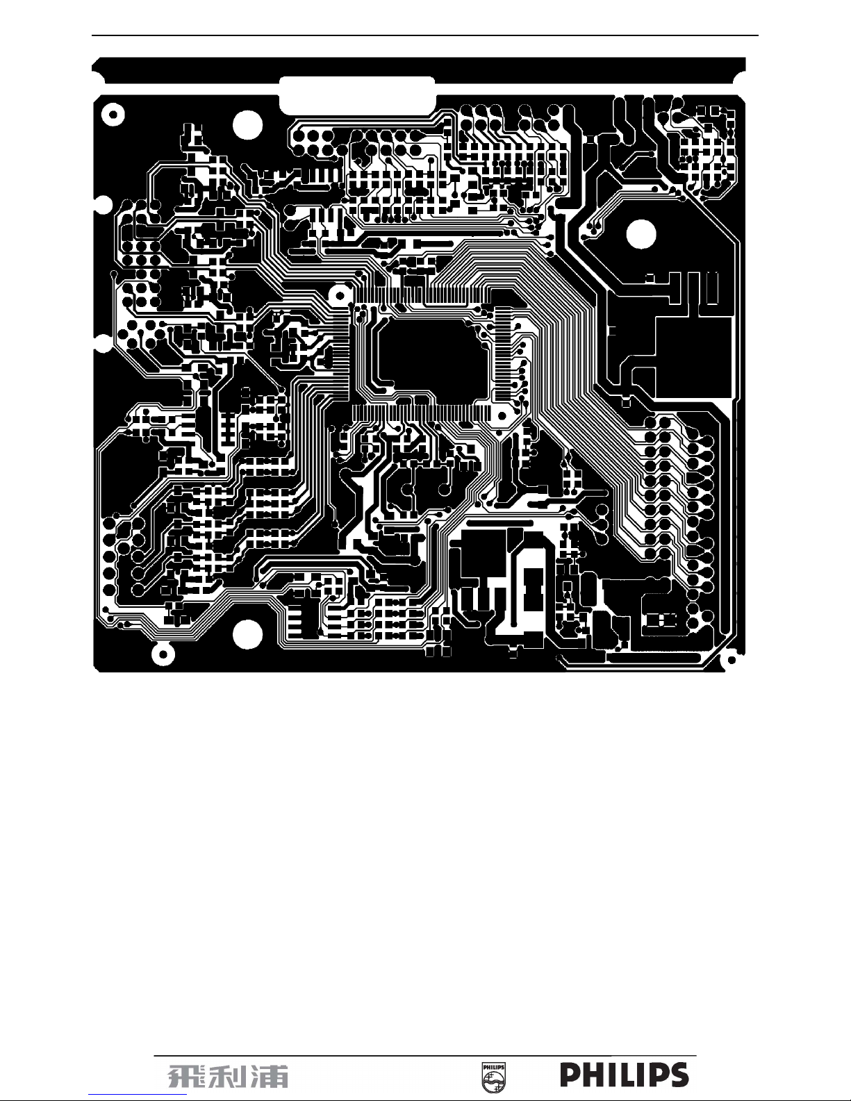
7. PCB Layout
7.1 Main Board
715G1767-1
19” LCD Color Monitor 190B7
30
 Loading...