

Philips 17PF7835, 15LCD35 Schematic


IMPORTANT SAFETY NOTICE
Proper service and repair is important to the safe, reliable operation of all Philips
Consumer Electronics Company** Equipment. The service procedures recommended by
Philips and described in this service manual are effective methods of performing service
operations. Some of these service operations require the use of tools specially designed
for the purpose. The special tools should be used when and as recommended.
It is important to note that this manual contains various CAUTIONS and NOTICES
which should be carefully read in order to minimize the risk of personal injury to service
personnel. The possibility exists that improper service methods may damage the
equipment. It also is important to understand that these CAUTIONS and NOTICES
ARE NOT EXHAUSTIVE. Philips could not possibly know, evaluate and advise the
service trade of all conceivable ways in which service might be done, or of the possible
hazardous consequences of each way. Consequently, Philips has not undertaken any such
broad evaluation. Accordingly, a servicer who uses a service procedure or tool which is
not recommended by Philips must first satisfy himself thoroughly that neither his safety
nor the safe operation of the equipment will be jeopardized by the service method
selected.
** Hereafter throughout this manual, Philips Consumer Electronics Company will be
referred to as Philips.
WARNING
Critical components having special safety characteristics are identified with a or
"S" by the Ref. No. in the parts list and enclosed within a broken line* (where
several critical components are grouped in one area) along with the safety symbol
on the schematics or exploded views. Use of substitute replacement parts which
do not have the same specified safety characteristics may create shock, fire, or other
hazards. Under no circumstances should the original design be modified or altered
without written permission from Philips. Philips assumes no liability, express or
implied, arising out of any unauthorized modification of design. Servicer assumes all
liability.
* Broken Line ____ _ ____ _ ____ _ ____

FIRE AND SHOCK HAZARD
1. Be sure all components are positioned in such a way as to avoid the possibility of adjacent component
shorts. This is especially important on those chassis which are transported to and from the service shop.
2. Never release a repaired unit unless all protective devices such as insulators, barriers, covers, strain
reliefs, and other hardware have been installed in accordance with the original design.
3. Soldering and wiring must be inspected to locate possible cold solder joints, solder splashes, sharp solder
points, frayed leads, pinched leads, or damaged insulation (including the ac cord). Be certain to remove
loose solder balls and all other loose foreign particles.
4. Check across-the-line components and other components for physical evidence of damage or
deterioration and replace if necessary. Follow original layout, lead length, and dress.
5. No lead or component should touch a receiving tube or a resistor rated at 1 watt or more. Lead tension
around protruding metal surfaces or edges must be avoided.
6. Critical components having special safety characteristics are identified with an 'S' by the Ref. No. in the
parts list and enclosed within a broken line* (where several critical components are grouped in one area)
along with the safety symbol on the schematic diagrams and /or exploded views.
7. When servicing any unit, always use a separate isolation transformer for the chassis. Failure to use a
separate isolation transformer may expose you to possible shock hazard, and may cause damage to
servicing instruments.
8. Many electronic products use a polarized ac line cord (one wide pin on the plug). Defeating this safety
feature may create a potential hazard to the servicer and the user. Extension cords which do not
incorporate the polarizing feature should never be used.
9. After reassembly of the unit, always perform an ac leakage test or resistance test from the line cord to all
exposed metal parts of the cabinet. Also, check all metal control shafts (with knobs removed), antenna
terminals, handles, screws, etc., to be sure the unit may be safely operated without danger of electrical
shock.
* Broken line ____ _ ____ _ ____ _ ____

LEAKAGE CURRENT COLD CHECK
1. Unplug the ac line cord and connect a jumper between the two prongs of the plug.
2. Turn on the power switch.
3. Measure the resistance value between the jumpered ac plug and all exposed cabinet parts of the receiver,
such as screw heads, antennas, and control shafts. When the exposed metallic part has a return path to the
chassis, the reading should be between 1 megohm and 5.2 megohms. When the exposed metal does not
have a return path to the chassis, the reading must be infinity. Remove the jumper from the ac line cord.
LEAKAGE CURRENT HOT CHECK
1. Do not use an isolation transformer for this test. Plug the completely reassembled receiver directly into
the ac outlet.
2. Connect a 1.5k, 10W resistor paralleled by a 0.15uF. capacitor between each exposed metallic cabinet
part and a good earth ground such as a water pipe, as shown below.
3. Use an ac voltmeter with at least 5000 ohms/volt sensitivity to measure the potential across the resistor.
4. The potential at any point should not exceed 0.75 volts. A leakage current tester may be used to make
this test; leakage current must not exceed 0.5mA. If a measurement is outside of the specified limits,
there is a possibility of shock hazard. The receiver should be repaired and rechecked before returning it
to the customer.
5. Repeat the above procedure with the ac plug reversed. (Note: An ac adapter is necessary when a
polarized plug is used. Do not defeat the polarizing feature of the plug.)
OR
With the instrument completely reassembled, plug the ac line cord directly into a 120Vac outlet. (Do not
use an isolation transformer during this test.) Use a leakage current tester or a metering system that
complies with American National Standards Institute (ANSI) C101.1 Leakage Current for Appliances and
Underwriters Laboratories (UL) 1410, (50.7). With the instrument ac switch first in the on position and
then in the off position, measure from a known earth ground (metal water pipe, conduit, etc.) to all exposed
metal parts of the instrument (antennas, handle brackets, metal cabinet, screw heads, metallic overlays,
control shafts, etc.), especially any exposed metal parts that offer an electrical return path to the chassis.
Any current measured must not exceed 0.5mA. Reverse the instrument power cord plug in the outlet and
repeat the test. See the graphic below.


TV SAFETY NOTES
SAFETY CHECKS
After the original service problem has been corrected, a complete safety check should be made. Be sure to
check over the entire set, not just the areas where you have worked. Some previous servicer may have left
an unsafe condition, which could be unknowingly passed on to your customer. Be sure to check all of the
following:
Fire and Shock Hazard
Implosion
X-Radiation
Leakage Current Cold Check
Leakage Current Hot Check
Picture Tube Replacement
Parts Replacement
WARNING: Before removing the CRT anode cap, turn the unit OFF and short the HIGH VOLTAGE to
the CRT DAG ground.
SERVICE NOTE: The CRT DAG is not at chassis ground.
IMPLOSION
1. All picture tubes used in current model receivers are equipped with an integral implosion system.
Care should always be used, and safety glasses worn, whenever handling any picture tube. Avoid
scratching or otherwise damaging the picture tube during installation.
2. Use only replacement tubes specified by the manufacturer.
X-RADIATION
1. Be sure procedures and instructions to all your service personnel cover the subject of X-radiation.
Potential sources of X-rays in TV receivers are the picture tube and the high voltage circuits. The
basic precaution which must be exercised is to keep the high voltage at the factory recommended
level.
2. To avoid possible exposure to X-radiation and electrical shock, only the manufacturer's specified
anode connectors must be used.
3. It is essential that the service technician has an accurate HV meter available at all times. The
calibration of this meter should be checked periodically against a reference standard.
4. When the HV circuitry is operating properly there is no possibility of an X-radiation problem. High
voltage should always be kept at the manufacturer's rated value - no higher - for optimum
performance. Every time a color set is serviced, the brightness should be run up and down while
monitoring the HV with a meter to be certain that the HV is regulated correctly and does not exceed
the specified value. We suggest that you and your technicians review test procedures so that HV and
HV regulation are always checked as a standard servicing procedure, and the reason for this prudent
routine is clearly understood by everyone. It is important to use an accurate and reliable HV meter. It
is recommended that the HV reading be recorded on each customer's invoice, which will
demonstrate a proper concern for the customer's safety.

5. When troubleshooting and making test measurements in a receiver with a problem of excessive high
voltage, reduce the line voltage by means of a Variac to bring the HV into acceptable limits while
troubleshooting. Do not operate the chassis longer than necessary to locate the cause of the excessive
HV.
6. New picture tubes are specifically designed to withstand higher operating voltages without creating
undesirable X-radiation. It is strongly recommended that any shop test fixture which is to be used
with the new higher voltage chassis be equipped with one of the new type tubes designed for this
service. Addition of a permanently connected HV meter to the shop test fixture is advisable. The
CRT types used in these new sets should never be replaced with any other types, as this may result in
excessive X-radiation.
7. It is essential to use the specified picture tube to avoid a possible X-radiation problem.
8. Most TV receivers contain some type of emergency "Hold Down" circuit to prevent HV from rising
to excessive levels in the presence of a failure mode. These various circuits should be understood by
all technicians servicing them, especially since many hold down circuits are inoperative as long as
the receiver performs normally.
PICTURE TUBE REPLACEMENT
The primary source of X-radiation in this television receiver is the picture tube. The picture tube
utilized in this chassis is specially constructed to limit X-radiation emissions. For continued Xradiation protection, the replacement tube must be the same type as the original, including suffix letter,
or a Philips approved type.
PARTS REPLACEMENT
Many electrical and mechanical parts in Philips television sets have special safety related
characteristics. These characteristics are often not evident from visual inspection nor can the protection
afforded by them necessarily be obtained by using replacement components rated for higher voltage,
wattage, etc. The use of a substitute part which does not have the same safety characteristics as the
Philips recommended replacement part shown in this service manual may create shock, fire, or other
hazards.
PRODUCT SAFETY GUIDELINES FOR ALL PRODUCTS
CAUTION: Do not modify any circuit. Service work should be performed only after you are thoroughly
familiar with all of the following safety checks. Risk of potential hazards and injury to the user increases if
safety checks are not adhered to.
USE A SEPARATE ISOLATION TRANSFORMER FOR THIS UNIT WHEN SERVICING.

PREVENTION OF ELECTROSTATIC DISCHARGE (ESD)
Some semiconductor solid state devices can be damaged easily by static electricity. Such components
commonly are called Electrostatically Sensitive (ES) Devices, Examples of typical ES devices are
integrated circuits and some field-effect transistors and semiconductor "chip" components. The following
techniques should be used to help reduce the incidence of component damage caused by electrostatic
discharge (ESD).
1. Immediately before handling any semiconductor component or semiconductor-equipped assembly, drain
off any ESD on your body by touching a known earth ground. Alternatively, obtain and wear a
commercially available discharging ESD wrist strap, which should be removed for potential shock
reasons prior to applying power to the unit under test.
2. After removing an electrical assembly equipped with ES devices, place the assembly on a conductive
surface such as aluminum foil, to prevent electrostatic charge buildup or exposure of the assembly.
3. Use only a grounded-tip soldering iron to solder or unsolder ES devices.
4. Use only an anti-static solder removal device. Some solder removal devices not classified as "antistatic
(ESD protected)" can generate an electrical charge sufficient to damage ES devices.
5. Do not use Freon propelled chemicals. These can generate electrical charges sufficient to damage ES
devices.
6. Do not remove a replacement ES device from its protective package until immediately before you are
ready to install it (most replacement ES devices are packaged with leads electrically shorted together by
conductive foam, aluminum foil or comparable conductive material).
7. Immediately before removing the protective material from the leads of a replacement ES device, touch
the protective material to the chassis or circuit assembly into which the device will be installed.
CAUTION: Be sure no power is applied to the chassis or circuit and observe all other safety precautions.
8. Minimize bodily motions when handling unpackaged replacement ES devices. (Otherwise harmless
motion such as the brushing together of your clothes fabric or the lifting of your feet from a carpeted
floor can generate static electricity (ESD) sufficient to damage an ES device.)
NOTE to CATV system Installer:
This reminder is provided to call the CATV system installer's attention to article 820-22 of the NEC that
provides guidelines for proper grounding and, in particular, specifies that the cable ground shall be
connected to the grounding system of the building, as close to the point of cable entry as practical.

PRACTICAL SERVICE PRECAUTIONS
IT MAKES SENSE TO AVOID EXPOSURE TO ELECTRICAL SHOCK. While some sources are
expected to have a possible dangerous impact, others of quite high potential are of limited current and are
sometimes held in less regard.
ALWAYS RESPECT VOLTAGES. While some may not be dangerous in themselves, they can cause
unexpected reactions – reactions that are best avoided. Before reaching into the powered color TV set, it is
best to test the high voltage insulation. It is easy to do, and is just a good service precaution.
BEFORE POWERING UP THE TV WITH THE BACK OFF (or on a test fixture), attach a clip lead to
the CRT DAG ground and to a screwdriver blade that has a well insulated handle. After the TV is powered
on and high voltage has developed, probe the anode lead with the blade, starting at the bottom of the High
Voltage Transformer (flyback – IFT). Move the blade to within two inches of the connector of the CRT. IF
THERE IS AN ARC, YOU FOUND IT THE EASY WAY, WITHOUT GETTING A SHOCK! If
there is an arc to the screwdriver blade, replace the High Voltage Transformer or the lead, (if removable)
whichever is causing the problem.
PICTURE TUBE REPLACEMENT PROCEDURE
Note: a. Two (2) people are required to handle this picture tube.
b. Safety Glasses must be worn during this procedure or whenever directly handling a picture tube.
c. Take care in each step not to damage the CRT or the cabinet.
1. Remove the Chassis and the CRT Socket Board Module from the cabinet.
2. A furniture pad or blanket should be positioned on the floor to support only the CRT Face. This pad or
blanket should be high enough to keep the CRT Face approximately 12 to 14 inches off the floor.
3. Using two people, place the cabinet in a front down position with the CRT Face on the pad or blanket.
4. Place padded blocks under each corner of the cabinet to keep it from rocking.
5. Remove the four screws, at the corners of the CRT.
6. With two people lowering the cabinet to the floor, leave the CRT elevated by the pad or blanket.
Note: Take care not to grasp the neck of the CRT during this procedure, as it is extremely fragile.
7. Two (2) people may then lift the CRT from the cabinet.
8. Remove the degaussing coil from the defective CRT and mount on the replacement. Take care to
maintain the exact shape and fit.
To install the new CRT, reverse steps 1 to 7.

GENERAL INFORMATION
Manual 7631, Model 15PF992517
Introduction:
Available in the first quarter of 2002, the 15PF9925 is a 15 inch LCD TV/Monitor.
The technology involved is advanced and highly integrated, dedicated electronics are present.
The set consists of the assemblies:
•
LCD panel
•
Main Chassis panel
•
Control panel
•
Tuner Pack
The LCD panel is a non-repairable assembly. Defective LCD panels will be returned to the supplier.
Main Chassis, Control and Tuner Pack are panels that can be repaired down to component level.
LCD TV/Monitor
Features:
•
TFT LCD 1024x768 pixels
•
brightness: 400cd/m2
•
contrast ratio: 300:1
•
de-interlacing
•
comb filter
•
integrated TV tuner
•
100 presets
•
stereo (2-carrier + NICAM)
•
TOP/FLOF teletext (8-p. memory)
•
integrated sound system
•
2x1 Watt RMS
•
graphic equalizer
•
Euro-A/V / SCART
•
cvbs-in
•
Y/C-in
•
headphones out
•
PC-in (up to XGA 1024x768/85Hz)
•
ARCH table-top stand incl.
•
optional wall-bracket

ADJUSTMENTS & TROUBLESHOOTING
- Model 15PF99, Manual 7631
Notes:
(1) This set uses an adapter, so connect the adapter and the set correctly before adjustment.
(2) The adjustment must be performed under the correct sequence.
(3) The adjustment must be performed in the circumstance of 25°+/-5C of temperature and 65+/-10% of relative
humidity if there is no specific designation.
(4) The input voltage of the receiver must keep 100~220V, 50/60Hz in adjusting.
(5) The set must be operated for 30 minutes preliminarily before adjustment if there is no specific designation.
* “Heat Run” must be performed with the full white signal or TV noise signal in the internal part of the set.
* The time for “Heat Run” can be changed owing to production plan.
PC Input Mode Adjustment
Required Test Equipment
(1) A pattern generator being in proportion to VG819; Pattern of 64 tones
(2) A remote control
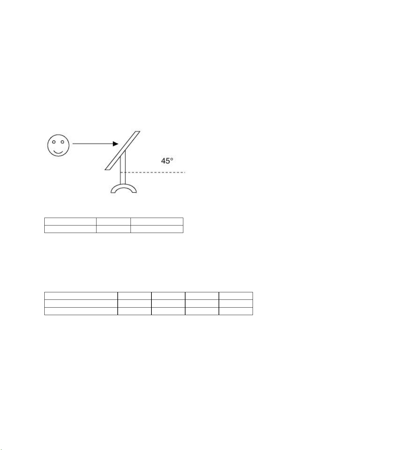
Preparation for Adjustment
(1) Perform “Heat Run” for more than 30 minutes in white pattern.
(2) Connect the signal of pattern generator with LCD TV.
(3) Lean the set 45° backward. (Adjustment is easy.)
(4) Set the PC mode menu as below.
Contrast Brightness
Initial Value 70 100
White Adjustment
(1) Approve the signal of 64 tones of XGA (1024 * 768).
(2) Select all the gain of R, B and G with using ADJ of remote control.
(3) After making 62 tones, 63 tones and 64 tones not distinguished with using each signal of R, G and B, finish
adjusting at the moment when the signal 62, 63 and 64 is distinguished.
R G B Error
Color Coordinates (x, y) 0.63 0.34 0.30 0.60 0.14 0.10 +/- 0.03
AD9884 0x02 0x03 0x04 Register

Position of Mode Adjustment
Mode VGA-60 VGA-67 VGA-72 VGA-75 VGA-85 TEXT-70 SVGA-56 SVGA-60 SVGA-72
H_Total 800 864 832 840 832 900 1024 1056 1040
H_Display 640 640 656 640 640 720 800 800 800
H_Blanking 160 224 176 200 192 180 224 256 240
H_Sync 96 64 40 64 56 108 72 128 120
H Polarity NEG. NEG. NEG. NEG. NEG. NEG. POS POS POS
H_Bp 48 96 120 120 80 54 128 88 64
H_Fp 16 64 16 16 56 18 24 40 56
H-Freq[KHz]
/Clk[MHz]
V_Total 525 525 520 500 509 449 625 628 666
V_Display 480 480 496 480 480 400 600 600 600
V_Blanking 45 45 24 20 29 49 25 28 66
V_Sync 2 3 3 3 3 2 2 4 6
V Polarity NEG NEG NEG NEG NEG POS POS POS POS
V_Bp 33 39 20 16 25 34 22 23 23
V_Fp 10 3 1 1 1 13 1 1 37
31.469
25.175
35.0
30.24
37.861
31.5
37.5
31.5
43.269
36.0
31.469
28.324
35.156
36.0
37.879
40.0
48.077
50.0
Mode SVGA-75 SVGA-85 XGA-60 XGA-70 XGA-75 MAC-75 XGA-85 VGA-70
H_Total
H_Display
H_Blanking
H_Sync
H Polarity
H_Bp
H_Fp
H-Freq[KHz]
/Clk[MHz]
V_Total
V_Display
V_Blanking
V_Sync
V Polarity
V_Bp
V_Fp
1056 1048 1344 1328 1312 1152 1376 800
800 800 1024 1024 1024 832 1024 640
256 248 320 304 288 320 352 160
80 64 136 136 96 64 96 96
POS POS NEG NEG POS NEG POS POS
160 152 136 144 176 224 208 48
16 32 160 24 16 32 48 16
46.875
49.5
53.674
56.25
48.363
65.0
56.476
75.0
60.023
78.75
49.725
57.283
68.677
84.997
31.468
70.090
625 631 806 806 800 667 808 449
600 600 768 768 768 624 768 350
25 31 38 38 32 43 40 99
3 3 6 6 3 3 3 2
POS POS NEG NEG POS NEG POS NEG
21 27 29 29 28 39 36 35
1 1 3 3 1 1 1 12

TROUBLESHOOTING
General Features
No. Symptom Cause Check Point
1 Soft touch doesn’t
function properly
2 Soft touch doesn’t
function
3 No screen Input error of inverter connector 1) Bend the pin legs of P801 connector -> recheck them
4 Dark screen 1) Defective LCD lamp
5 Broken OSD display Defective the font rom of IC505 Replace the font rom of IC505
PC Mode
No. Symptom Cause Check Point
6 Screen noise Clock or phase being
7 Screen position error Screen position error
8 Color beat noise Soldering AD converter
TV and external input
No. Symptom Cause Check Point
9 No sound
- Speaker
- Earphone
10 Video color beat noise Earphone shield case being
Soldering IC301 and IC501 Re-soldering
Defective speaker wire
and inverter wire
1) Broken components and
soldering of them
2) P401 connector error
P502 and Pin 21 connector
being slipped out
Cracked components and
soldering at tuner board
2) Defective inverter
not able to be adjusted
horizontally or vertically
or making it short
Defective Reset IC of IC603
Defective MSP3440 of IC601
touched
1) Make some space between the speaker wire and
the Soft touch Board by sticking the speaker wire
to the guide hole of the cabinet.
2) Arrange working state of A1. Tape in the inverter wire
and correct working state of the Shield case.
1) Check Soft touch with eyes
Check and repair soldering
2) Check and repair the P401 connector
2) Check and repair the IC801, IC802 SI4925
1) Check and fix P502 connector
2) Check and fix the components at P502 LCD module
and at main board.
1) Check and repair tuner board and main board
2) Solder Q301, Q302, Q402, Q403, Q801 and R802.
1) Replace the inverter
2) Replace the LCD lamp
1) Resetting is needed according to the video card of each
PC
2) Adjust auto configure operation.
Adjust horizontal and vertical position until the screen
displays normally
Recheck and repair AD9884
1) Check volume and speaker
- Sound comes out only when being inputted into
Audio L/R
2) Check after replacing IC603
3) Replace IC601
Check the mould of shield and J403, Replace shield
case

All Models (7631) - Panel Interconnect

All Models (7631) - Main Panel Schematic

All Models (7631) - Tuner Panel Schematic
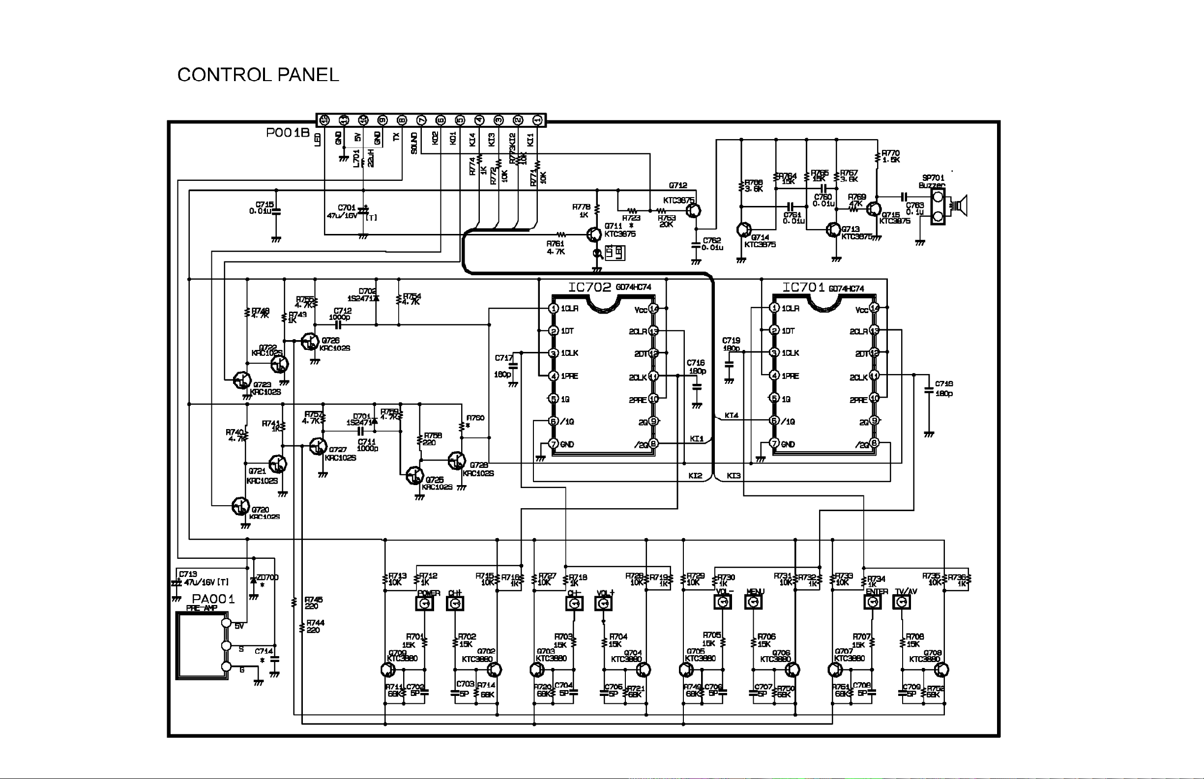
All Models (7631) - Control Panel Schematic
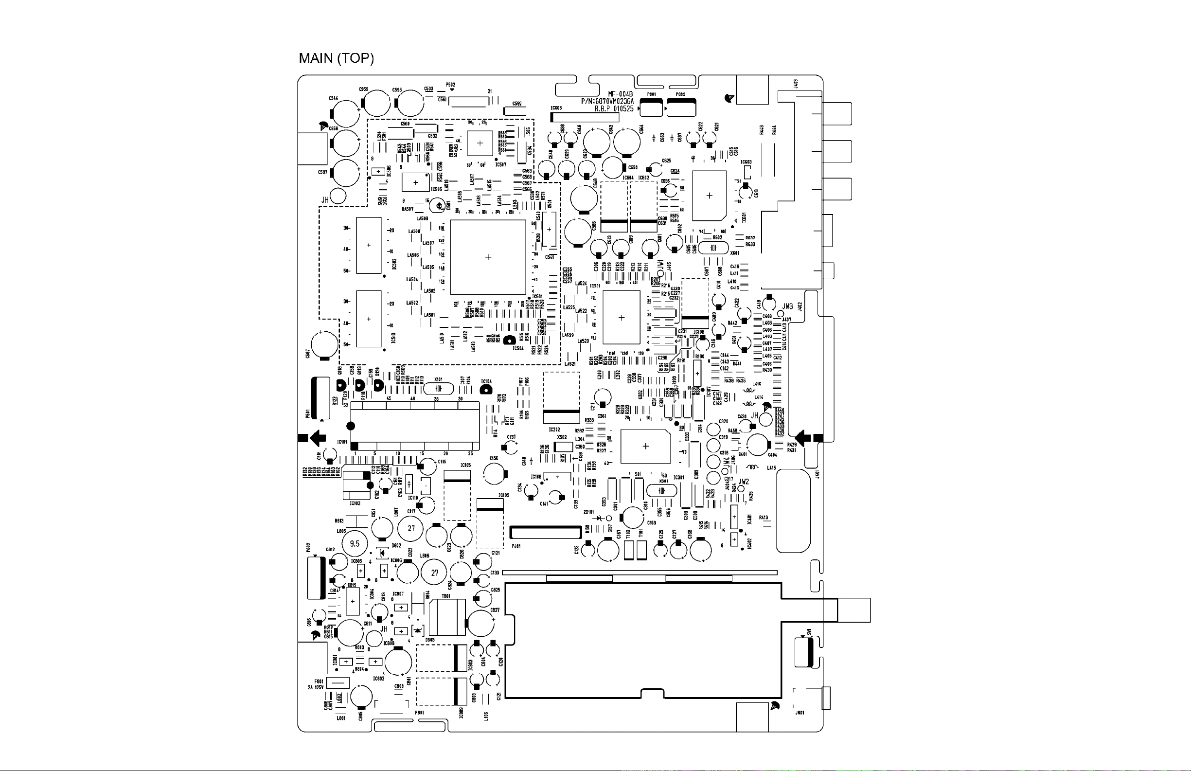
All Models (7631) - Main PCB (Top View only)

All Models (7631) - Tuner PCB (Both Views)

All Models (7631) - Control PCB (Top View only)
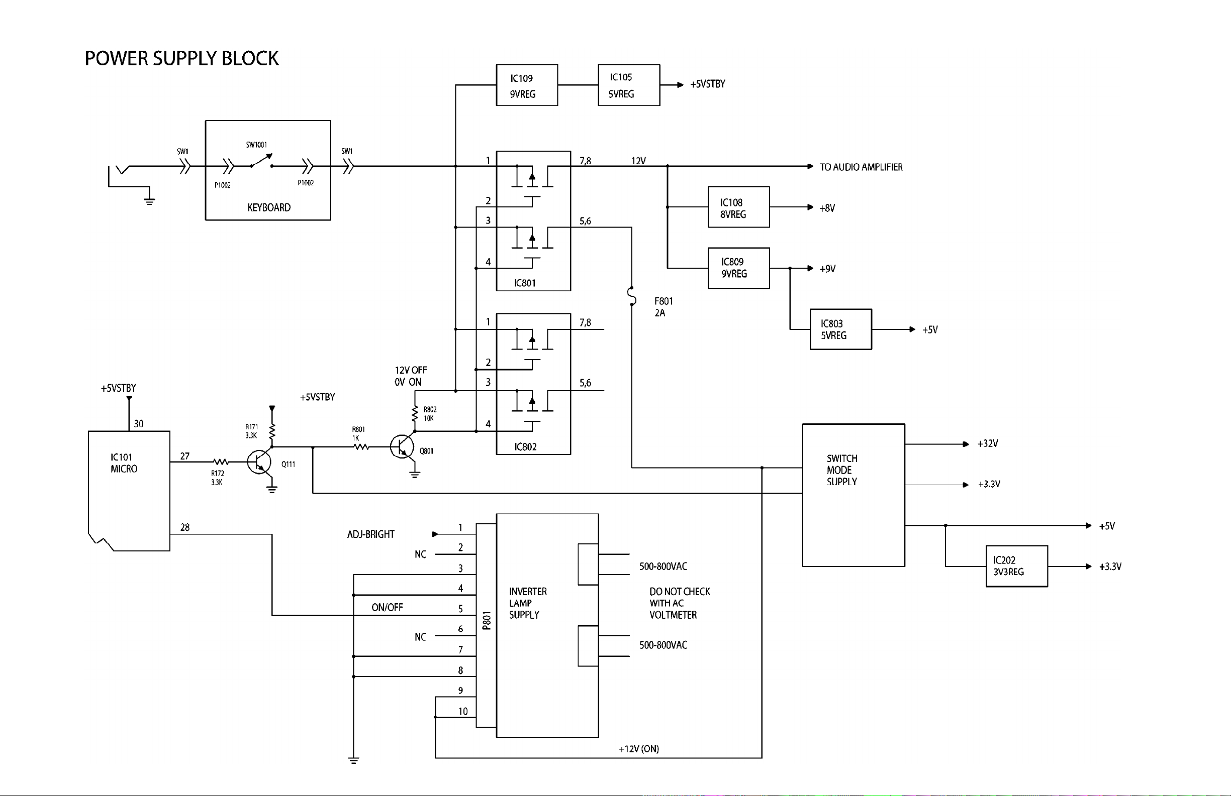
All Models (7631) - Power Supply Block

All Models (7631) - Video Signal Flow Block

All Models (7631) - Audio Signal Flow Block
 Loading...