

Horizontal frequencies
30 - 83kHz
Service
Service
Service
TABLE OF CONTENTS
Published by BCU Monitors Printed in suzhou Copyright reserved Subject to modification F Apr .1 2005
Description Page
Important Safety Notice---------------------------------- 2
Technical Data/Installation---------------------------3~7
On-Screen Display/Aging Mode---------------------8~9
Mechanical instructions----------------------------13~14
Trouble shooting-------------------------------------17~18
Factory Mode/Pixel defect policy-----------------10~12
Display adjustment/Warning message----------15~16
Electrical Instructions-------------------------------19~22
LightFrameDR----------------------------------------23~24
Safety Test Requirements------------------------------25
DDC Instructions/DATA----------------------------26~34
ISP Instructions--------------------------------------35~37
Wiring Diagram---------------------------------------38~39
Description Page
Block Diagram--------------------------------------------40
Scaler Diagram/C.B.A-----------------------------41~52
USB Diagram/C.B.A--------------------------------53~58
Audio Diagram/C.B.A------------------------------59~60
Control&Audio Diagram/C.B.A-------------------61~63
Power Diagram/C.B.A-----------------------------64~66
Exploded View-------------------------------------- 67~68
Recommended Parts list-------------------------------69
Spare Parts list--------------------------------------70~72
Different parts list----------------------------------73~76
Repair Tips/Repair Flow Chart-------------------77~81
General product specification------------------82~110
REFER TO BACK COVER FOR IMPORTANT SAFETY GUIDELINES
CAUTION: USE A SEPARATE ISOLATION TRANSFORMER FOR THIS UNIT WHEN SERVICING.
ANY PERSON ATTEMPTING TO SERVICE THIS CHASSIS MUST FAMILIARIZE HIMSELF WITH THE CHASSIS
AND BE AWARE OF THE NECESSARY SAFETY PRECAUTIONS TO BE USED WHEN SERVICING ELECTRONIC
EQUIPMENT CONTAINING HIGH VOLTAGES.
SAFETY NOTICE
Family: SH6L
GB
3138 106 10460
PHILIPS LCD Monitor
190P6ES/00
190P6EB/27
190P6EG/00
190P6EG/93
190P6EB/00
170P6EB/93
170P6EG/00
170P6EG/93
170P6ES/00
170P6EB/27

Important Safety Notice
2
FOR PRODUCTS CONTAINING LASER :
Invisible laser radiation when open.
AVOID DIRECT EXPOSURE TO BEAM.
Use of controls or adjustments or
performance of procedures other than
those specified herein may result in
hazardous radiation exposure.
The use of optical instruments with this
product will increase eye hazard.
DANGER-
CAUTION-
CAUTION-
TO ENSURE THE CONTINUED RELIABILITY OF
THIS
PRODUCT, USE ONLY ORIGINAL
MANUFACTURER'S REPLACEMENT PARTS,
WHICH ARE LISTED WITH THEIR PART NUMBERS
IN THE PARTS LIST SECTION OF THIS SERVICE
190P6&170P6 LCD
Proper service and repair is important to the safe,
reliable operation of all Philips Consumer Electronics
Company** Equipment. The service procedures
recommended by Philips and described in this service
manual are effective methods of performing service
operations. Some of these service operations require
the use of tools specially designed for the purpose. The
special tools should be used when and as
recommended.
It is important to note that this manual contains various
CAUTIONS and NOTICES which should be carefully
read in order to minimize the risk of personal injury to
service personnel. The possibility exists that improper
service methods may damage the equipment. It is also
important to understand that these CAUTIONS and
NOTICES ARE NOT EXHAUSTIVE. Philips could not
possibly know, evaluate and advise the service trade of
all conceivable ways in which service might be done or
of the possible hazardous consequences of each way.
Consequently, Philips has not undertaken any such
broad evaluation. Accordingly, a servicer who uses a
service procedure or tool which is not recommended by
Philips must first satisfy himself thoroughly that neither
his safety nor the safe operation of the equipment will
be jeopardized by the service method selected.
* * Hereafter throughout this manual, Philips Consumer
Electronics Company will be referred to as Philips.
WARNING
Critical components having special safety
characteristics are identified with a by the Ref. No.
in the parts list and enclosed within a broken line*
(where several critical components are grouped in one
area) along with the safety symbol on the
schematics or exploded views.
Use of substitute replacement parts which do not have
the same specified safety characteristics may create
shock, fire, or other hazards.
Under no circumstances should the original design be
modified or altered without written permission from
Philips. Philips assumes no liability, express or implied,
arising out of any unauthorized modification of design.
Servicer assumes all liability.
* Broken Line
Take care during handling the LCD module with
Backlight unit
- Must mount the module using mounting holes
arranged in four corners.
- Do not press on the panel, edge of the frame
strongly or electric shock as this will result in
damage to the screen.
- Do not scratch or press on the panel with any sharp
objects, such as pencil or pen as this may result in
damage to the panel.
- Protect the module from the ESD as it may damage
the electronic circuit (C-MOS).
- Make certain that treatment person s body are
grounded through wrist band.
- Do not leave the module in high temperature and in
areas of high humidity for a long time.
- Avoid contact with water as it may a short circuit
within the module.
- If the surface of panel become dirty, please wipe it
off with a soft material. (Cleaning with a dirty or
rough cloth may damage the panel.)
Go to cover page
3
190P6&170P6 LCD
Go to cover page
Technical Data(For 190P6)
1. General
1.1.1Product description
190P6 is the 6th generation ofHudson 19 TFT Flat Panel Display
Monitor. The monitor featuredwith both DVI-Dand analog signal
inputinterface, andmodularized as a displayunit with embedded
universal AC power supplies inside monitor main body. The power
button anddispla
y control buttons (tact switch type) are on the front
of the monitor. The monitor shall support an internal scaler to
automatically enable the monitor to display lower resolution video
modes into 1280 x 1024 full screen display. The image can be
adjusted through OSDcontrolboard. Theseadjustments can be
store
d on a boardmemory including 34 pre-set modes and 16
factory pre-set modes.
1.1.2 Destination:AP, CN, EE, GB, LA, ME, SH, WE
1.2. Basic data
1.2.1 LCD panel
1.2.1.1Type NR. : LM190E04-A4K4 (LPL)
Number of Pixels. : 1280(H) x1024 (V)
Physical Size
.:396.0(w)*324.0(h)*15.5(d) mm
Pixel Pitch.:0.098 (per one triad) x 0.264mm
Color pixel arrangement :RGB vertical stripes
Support Color.:16.2M colors (RGB8bitsdata)
DisplayMode.:NormallyWhite
Backlight.:CCFL edge light system
Active area. (WXH).:376.32 x 301.056
mm (19 diagonal)
Viewing Angle.:Vertical 140 degree,Horizontal
140 degree (CR=10)
Contrastratio.:500:1
White luminance.:250nits (Typ)
1.2.2. Power supply
Main Voltage:AC90 - 135 Vrms and 170 -264Vrms, 50/60±2Hz
Power consumption:55wattsmax (full loading,with 4X USB
devices on downstream ports, each device consumes 0.5 Amp)
Operating < 43W(typical value; no device loading on USB
downstream port(s)) stan
dby<1W.
DC power switch off < 1W (no device loading on USB downstream
port(s))
Power cord length: 1.5M
Power cord type:3leadwith earth plug
Power indicator:LED(ON: green,Standby: amber)
Auto power saving:EPA, Nutek, VESA, DPMS,
STATUS
H-
syncV-sync
Video
Powe
r
LED
On On On Active
<55WGreen /With Audio
andfull USB loading
On On On Active
<35
W
Green /Without
Audio andUSB
loading
Stand-by Off On Blanked<1W
Amber LED
SuspendOn Off Blanked<1W
Amber LED
Off Off Off Blanked<1WAmber LED
DC Power
off
N/A <1WLED Off
Note :
A. To achieve under 1 Watt power saving,make sure there is
no device load on USB downstream port(s).
B. To achieve under 1 Watt power saving when Stand-Alone Audio
feature isselectedOnand system is in Sleep Mode,follow
below twoconditions:
1.Volumehas to beadjuste
d to 0% prior to measurement.
2.Make sure there is no device load on USB downstream port(s).
1.2.3. Horizontal scan:30 -83KHz
1.2.4. Vertical scan:56 -76 Hz
"
"
"
"
1.2.5. Input signals
The input signals can be applied in two different modes:
1). VESA Analog
The video inputconsists of red, green, andblue signals. The video
signals are analog levels, where 0V corresponds to black and
700mV is the maximum signal amplitude.Inputimpedance o
f video
pins is75ohm+/-1%.
The capability ofsync signal inputsshall include separate sync,
composite sync andsync on green. inputimpedance:2k2ohms
The signals are defined asfollow:
Separate sync TTL level, Positive/Negative
Composite sync TTL level, Positive/Negative
Sync on green H-sync TTL level,
Positive/Negative
2).Intel DVI Digital
Input signal: Four channel TMDSsignals
Signal source: pattern generator format (Refer to the SPEC)
1.2.6 Audio
Amplifier and headphone section :
Outputpower:2x2Wrms into 16 Ohm
Input sensitivity: 500mVrms
Frequency range: 100Hz - 20KHz
Volum
econtrolkeypads are at the front control panel.
L/R inputvia1.8m hard-wired cable with limegreen3.5mm plug
Headphone connection will mute speakers.
Loudspeaker section :
Rated input 2.0W
Max. input 3.0W
Impedance 16 Ohm+/- 15%
Sensitivity76 dB +/-3 dB (at 1W/1m at 1KHz)
1.2.7 Input connectors
(1) I
nputanalogD-sub connector pin assignment
PIN No. SIGNAL
1 Red video input
2 Green video input /sync on green
3Bluevideo input
4 GND
5 GND
6 Red video GND
7 Green video GND
8Bluevideo GND
9DDC+3.3Vor +5V
10 Logic GND -Cable detect
11 GND
12Serial data line (SDA)
13H-sync /H+V
14V-sync
15 Data clock line (SCL)

4
190P6&170P6 LCD
Go to cover page
Technical Data(For 190P6)
(2) InputDVI-D connector pin assignment
Pin No. Description
1T.M.D.S. data2-
2 T.M.D.S. data2+
3 T.M.D.S. data2shield
4No Connect
5No Connect
6DDC clock
7 DDCdata
8No Connect
9T.M.D.S. data1-
10 T.M.D.S. data1+
11 T.M.D.S. data1 shield
12No Connect
13No Connect
14+5VPower
15Ground (for +5V) –Cable detect
16 Hot plug detect
17 T.M.D.S. data0-
18 T.M.D.S. data0+
19 T.M.D.S. data0 shield
20 No Connect
21 No Connect
22 T.M.D.S clockshield
23 T.M.D.S. clock+
24 T.M.D.S. clock-
Signal interface
15Pins, D-sub male with DDC-2B Pin assignments
24Pins, DVI-D male with DDC-2B Pin assignments
Sync polarity:
H-sync positive/negative
V-sync positive/negative
Lead-free Product
Philips elim inated toxic substances likeleadfrom itsdisplays.
Lead-free display helps protect your health andpromotes
environmentallysoun d recovery anddisposal ofwaste from
electrical and electronic equipment. Philips complieswith the
European Communitystringent R
oHS Directive mandating
restrictions on hazardous substances in electrical and electronic
equipment.With Philips, you can b econfid ent that your di splay
device does not harm the environment.
5
190P6&170P6 LCD
Go to cover page
Technical Data(For 170P6)
"
"
"
"
1. General
1.1.1Product description
170P6 is the 6th generation of Hudson 17 TFT Flat Panel Display
Monitor. The monitor featuredwith both DVI-Dand analog signal
input interface, andmodularized as a displayunit with embedded
universal AC power supplies inside monitor main body. The power
button anddispla
y control buttons (tact switch type) are on the front
of the monitor. The monitor shall support an internal scaler to
automatically enable the monitor to display lower resolution video
modes into 1280 x 1024 full screen display. The image can be
adjusted through OSDcontrolboard. Theseadjustments can be
store
d on a boardmemory including 34 pre-set modes and 16
factory pre-set modes.
1.1.2 Destination:AP, CN, EE, GB, LA, ME, SH, WE
1.2. Basic data
1.2.1 LCD panel
Type NR. : LM170E01-A6K3/A6K4 (LPL)
Number of Pixels. : 1280(H) x1024 (V)
Physical Size
. : 358.5(w)*296.5(h)*17.0(d) mm
Pixel Pitch.:0.264 (per one triad) x 0.264mm
Color pixel arrangement.:RGB vertical stripes
Support Color.:16.2M colors (RGB8bitsdata)
DisplayMode.:NormallyWhite
Backlight.:CCFL edge light system
Active area. (WXH).:337.92 x 270.336mm (17
diagonal)
Viewing Angle.:Vertical 140 degree,Horizontal
140 degree (CR=10)
Contrastratio.:500:1
White luminance.:250nits (Typ)
1.2.2. Power supply
Main Voltage:AC90 - 135 Vrms and 170-264Vrms, 50/60±2Hz
Power consumption:55wattsmax (full loading,with 4X USB
devices on down
stream ports, each device consumes 0.5 Amp)
Operating <35W(typical value; no device loading on USB
downstream port(s)) standby<1W.
DC power switch off < 1W (no device loading on USB
downstream port(s))
Power cord length: 1.5M
Power cord type:3leadwith earth plug
Power indicator:LED(ON: green,S
tandby: amber)
Auto power saving:EPA, Nutek, VESA, DPMS,
STATUS
H-
syncV-sync
Video
Powe
r
LED
On On On Active
<55
W
Green /With Audio
andfull USB
loading
On On On Active
<35
W
Green /Without
Audio andUSB
loading
Stand-by Off On Blanked<1W
Amber LED
SuspendOn Off Blanked<1W
Amber LED
Off Off Off Blanked<1WAmber LED
DC Power
off
N/A <1WLED Off
Note :
A. To achieve under 1 Watt power saving,make sure there is no
device load on USB downstream port(s).
B. To achieve under 1 Watt power saving when Stand-Alone
Audio feature isselectedOnand system is in Sleep Mode,
followbelow twoconditions:
1.Volumehas to beadjusted to 0% prior to measurement.
2.Make sure there is no device load on USB downstream port(s).
1.2.3.Horizontal scan:30 -83KHz
1.2.4.Vertical scan:56 - 76 Hz
1.2.5. Input signals
The input signals can be applied in two different modes:
1). VESA Analog
The video inputconsists of red, green, andblue signals. The video
signals are analog levels, where 0V corresponds to black and 700mV
is the maximum signal amplitude.Inputimpedance of
video pins is
75 ohm+/-1%.
The capability ofsync signal inputsshall include separate sync,
composite sync andsync on green. inputimpedance:2k2ohms
The signals are defined asfollow:
Separate sync TTL level, Positive/Negative
Composite sync TTL level, Positive/Negative
Sync on green H-sync TTL level,
Positive/Negative
2).Intel DVI Digital
Input signal: Four channel TMDSsignals
Signal source: pattern generator format (Refer to the SPEC)
1.2.6 Audio
Amplifier and headphone section :
Outputpower:2x2Wrms into 16 Ohm
Input sensitivity: 500mVrms
Frequency range: 100Hz - 20KHz
Volum
e control keypads are at the front control panel.
L/R inputvia1.8m hard-wired cable with limegreen3.5mm plug
Headphone connection will mute speakers.
Loudspeaker section :
Rated input 2.0W
Max. input 3.0W
Impedance 16 Ohm+/- 15%
Sensitivity 76 dB +/-3 dB (at 1W/1m at 1KHz)
1.2.7 Input connectors
(1) InputanalogD-sub connector pin assignment
PIN No. SIGNAL
1 Red video input
2 Green video input /sync on green
3Bluevideo input
4 GND
5 GND
6 Red video GND
7Greenvideo GND
8Bluevideo GND
9 DDC +3.3V or +5V
10 Logic GND -Cable detect
11 GND
12Serial data line (SDA)
13H-sync /H+V
14V-sync
15 Data clock line (SCL)

6
190P6&170P6 LCD
Go to cover page
Technical Data(For 170P6)
Lead-free Product
Philips elim inated toxic substances likeleadfrom itsdisplays.
Lead-free display helps protect your health andpromotes
environmentallysoun d recovery anddisposal ofwaste from
electrical and electronic equipment. Philips complieswith the
European Communitystringent R
oHS Directive mandating
restrictions on hazardous substances in electrical and electronic
equipment.With Philips, you can b econfid ent that your di splay
device does not harm the environment.
(2) InputDVI-D connector pin assignment
Pin No. Description
1T.M.D.S. data2-
2 T.M.D.S. data2+
3 T.M.D.S. data2shield
4No Connect
5No Connect
6DDC clock
7DDCdata
8No Connect
9 T.M.D.S. data1-
10 T.M.D.S. data1+
11 T.M.D.S. data1 shield
12No Connect
13No Connect
14+5VPower
15Ground (for +5V) –Cable detect
16 Hot plug detect
17 T.M.D.S. data0-
18 T.M.D.S. data0+
19 T.M.D.S. data0 shield
20 No Connect
21 No Connect
22 T.M.D.S clockshield
23 T.M.D.S. clock+
24 T.M.D.S. clock-
Signal interface
15Pins, D-sub male with DDC-2B Pin assignments
24Pins, DVI-D male with DDC-2B Pin assignments
Sync polarity:
H-sync positive/negative
V-sync positive/negative
7
190P6&170P6 LCD
Go to cover page
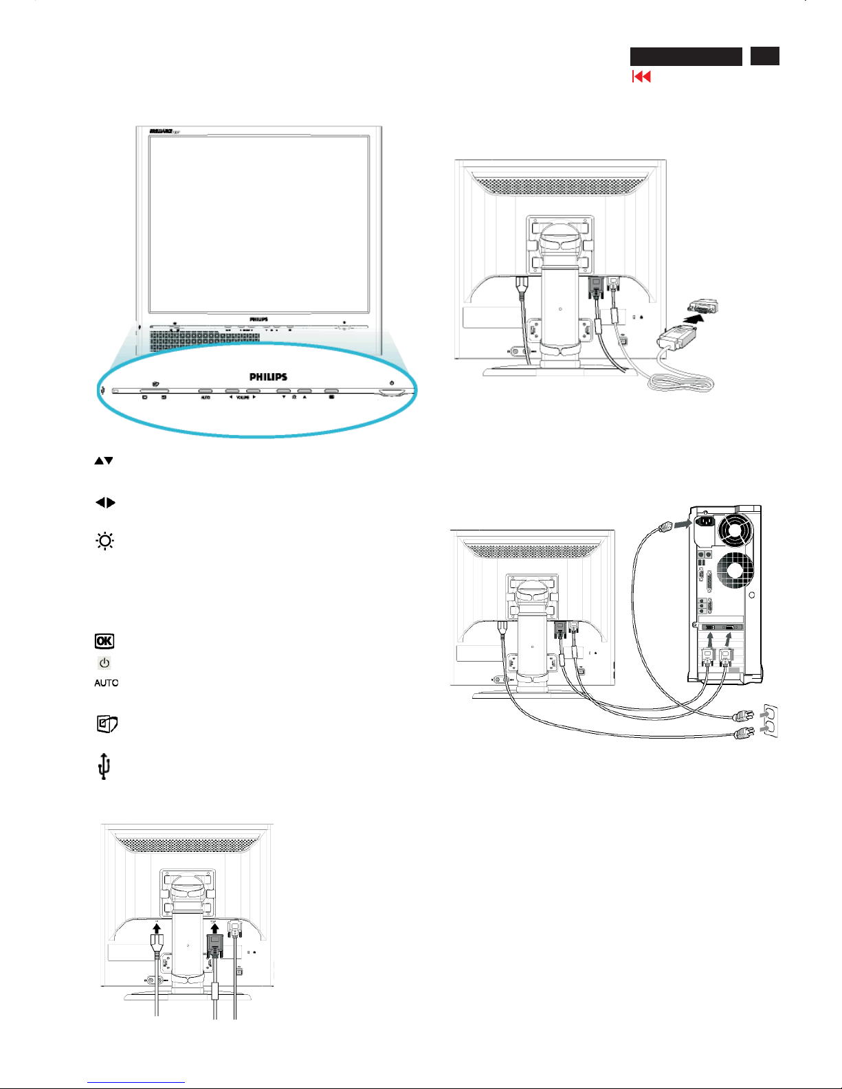
Connection to PC
Front view
UPandDOWNbuttons are used when adjusting the OSD ofyour
monitor.
LEFT andRIGHT buttons, likethe UPandDOWNbuttons, are
also used in adjusting the OSD ofyour monitor.
BRIGHTNESS hotkey. W hen the UPandDOWNarrow
buttons are pressed, theadjustment controls for the BRIGHTNESS
wi
ll show up.
VOLUME hotkey. W hen the LEFT andRIGHT arrow buttons are
pressed, theadjustment controls for VOLUME will show up.
OK button which when pressed will take you to the OSD controls
POWER button switchesyour monitor on.
Automatically adjustthe horizontal pos
ition, vertical position,
phaseand clocksetting.
LightFrame
TM
hotkeyfor mode-switching between full-screen mode
andmulti-window mode.
USB Hub for versatileperipheral connections
VOLUME
Connecting to PC
1) Pluginthecables into connectors
Note: If youuseanApple Macintosh, you need to connect the
specialMac adapter to one end of the monitor signal cable
(2) Connect to PC
(a) Turn off yourcomputer andunplugits power cable.
(b) Connect the monitor signal cabletothevideo connector on the
back ofyourcomputer.
(c) Plugthe power cord ofyourcomputer andyour monitor into a
nearby outlet.
(d) Turn on yourcomputer andmonitor.If
the monitor displays an
image, installation is complete.

8
190P6&170P6 LCD
Go to cover page
On Screen Display
On-Screen Display (OSD) is a feature in all Philips LCD monitors.Itallowsanenduser to adjust screen performance or selectfunctions
of the monitors directly through an on-screen instruction window. A user friendly on screen display interface is shownasbelow :
In theOSDshownleft users can press buttons
atthe frontbezel of the monitor to move thecursor,
to
confirmthechoice orchange, and
to adjust/selectthechange.
OSD Tree

9
190P6&170P6 LCD
Go to cover page
Front Control Panel
To Lock/Unlock OSD FUNCTION(User Mode)
The OSD function can be locked by pressing"OK"button(1) for more
than 10 seconds, the screen shows following windows for 3 seconds.
Everytime when you press"AUTO" or "OK" button, this message appears on the screen automatically.
ATTENTION SIGNAL
OSD MAIN CONTROLS UNLOCKED
Unlock OSD function
Locked OSD function can be released by pressing "OK" button for more
than 10 seconds again
ATTENTION SIGNAL
OSD MAIN CONTROLS LOCKED
NO VIDEO INPUT
This screen appears if there is no video signal input. Please check that
the signal is properly connected to the video card of PC and make sure
PC is on
ATTENTION SIGNAL
CHECK CABLE CONNECTION
CANNOT DISPLAY THIS VIDEO MODE..
This screen warns when the input frequency from the computer is not
a standard video mode or out of the monitor's scanning range.
Please change the display mode of the operating software in the computer(i.e.windows) to 1280*1024@60HZ for best display results.
ATTENTION SIGNAL
CANNOT DISPLAY THIS VIDEO
MODE,CHANGE COMPUTER DISPLAY
I
N
P
U
T
TO
1
2
8
0
*
1
0
2
4
@
6
0
H
Z
I
WAIT FOR AUTOMATIC ADJUSTMENT
This screen appears when you press the "AUTO" buttons at the same
time. It will disappear when the monitor is properly adjusted
ATTENTION SIGNAL
WAITING FOR AUTOMATIC ADJUSTMENT
Access Aging.. Mode
Step 1 : Turn off LCD monitor, and disconnect Interface Cable
between Monitor and PC.
Step 2 : [Push AUTO " " & " " buttons at the same time and
hold it]+[Press power " " button until comes out " AGING screen"
] => then release all buttons.
Bring up:
AGING...
After 15 seconds, bring up:
After 15 seconds, bring up:
AGING...
After 15 seconds, bring up:
----------
---------repeatly
Connect Signal cable again=> go back to normal display
OSD Lock/Unlock, Aging Mode
10
190P6&170P6 LCD
Go to cover page
Front Control Panel
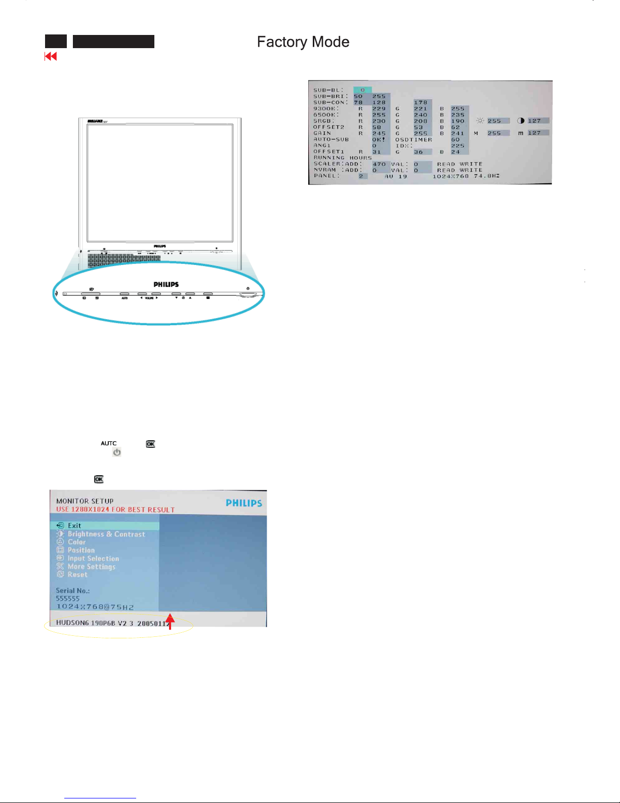
Access Factory Mode
How to get into Factory Mode Menu
Step1:
Turn off monitor.
Step2:
[Push AUTO " " & OK " " buttons at the same time and hold it]
+[Press power " " button untill comes out "Windows screen" ]
=> then release all buttons
Step3:
Press OK " " button, bring up Factory mode indication as shown
in Fig2.
Factory Mode indicator
Factory Menu
Cursor can move on gray color area
Hot key function: by pressing " up " and " DOWN " key
Simultaneously at User Mode (or Factory Mode)
(PS:TheOffsetRGBfunction can be used on reduce or eliminate
snowy noise on the background when the resolution of video signal
is 1280*1024 vertical 60Hz. Slightly increase or decrease the value
until snowy noise completely disappear
BL : Blacklevel value
SUB-BRI : Brightness value range(Min Max)
SUB-CON : Contrast value range(Min Mid Max)
SRGB-B : Brightness of sRGB
SRGB-C:ContrastofsRGB
Gain-m : Minimum value of User Gain
Gain-M:Maximum value of User Gain
AUTO-SUB: To do Auto color function when push Menu key in white
pattern
OSDTIMER : OSD time out control(sec)
ANG1 : For analog only project control (0:Dual, 1:Analog only)
IDX : Limit current of inverter
SCALER:Read/Write scaler register
NVRAM : Read/Write eeprom address
Panel : LG(LG.Philips panel)
11
190P6&170P6 LCD
Go to cover page
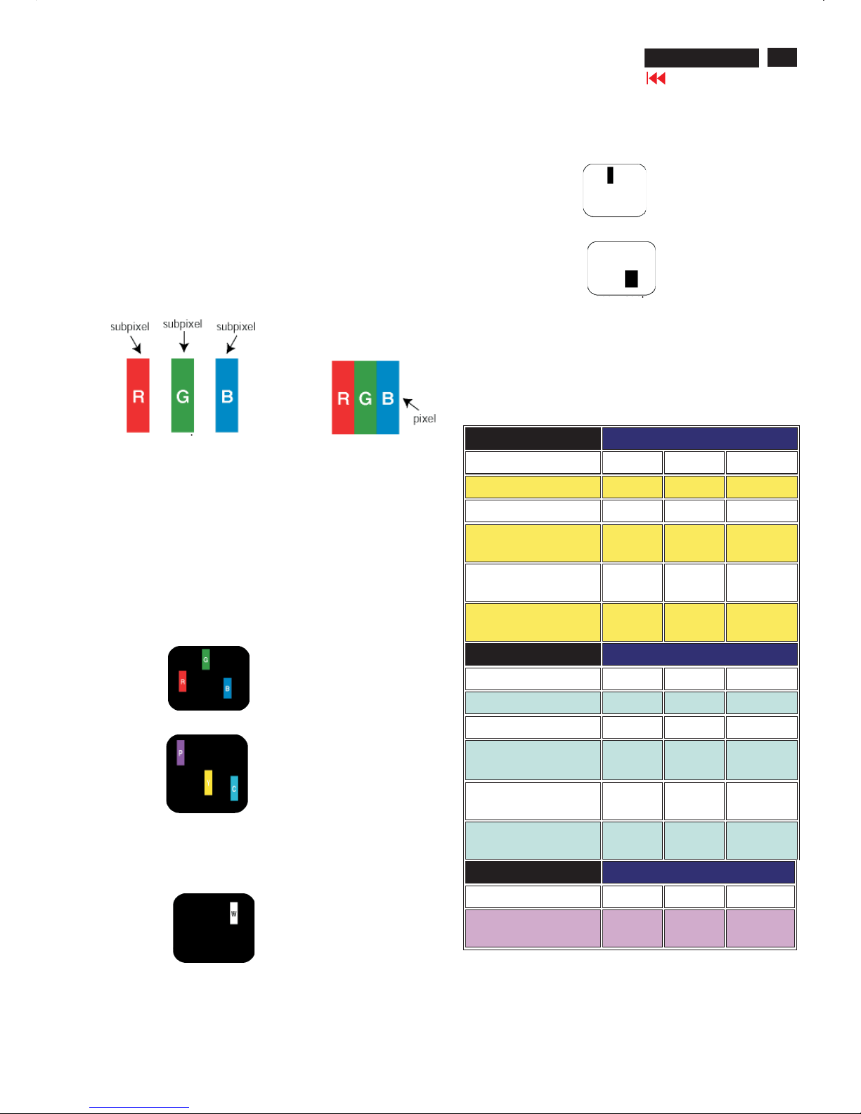
Philips' Flat Panel Monitors Pixel Defect Policy
Pixels and Subpixels
Types of Pixel Defects
Philips strives to deliver the highest quality products. We use some of
the industry's most advanced manufacturing processes and practice
stringent quality control. However, pixel or subpixel defects on the TFT
LCD panels used in flat panel monitors are sometimes unavoidable.
No manufacturer can guarantee that all panels will be free from pixel
defects, but Philips guarantees that any monitor with an unacceptable
number of defects will be repaired or replaced under warranty.
This notice explains the different types of pixel defects and defines
acceptable defect levels for each type. In order to qualify for repair or
replacement under warranty, the number of pixel defects on a TFT LCD
panel must exceed these acceptable levels.
For example, no more than 0.0004% of the subpixels on a 15" XGA
monitor may be defective. Furthermore, Philips sets even higher quality
standards for certain types or combinations of pixel defects that are
more noticeable than others. This policy is valid worldwide .
A pixel, or picture element, is composed of three subpixels in the
primary colors of red, green and blue. Many pixels together form an
image. When all subpixels of a pixel are lit, the three colored subpixels
together appear as a single white pixel. When all are dark, the three
colored subpixels together appear as a single black pixel.
Other combinations of lit and dark subpixels appear as single pixels of
other colors.
Pixel and subpixel defects appear on the screen in different ways.
There are two categories of pixel defects and several types of subpixel
defects within each category.
Bright Dot Defects Bright dot defects appear as pixels or subpixels that
are always lit or "on".
These are the types of bright dot defects:
One lit red, green or blue subpixel
Two adjacent lit subpixels:
-Red+Blue=Purple
-Red+Green=Yellow
- Green + Blue = Cyan (Light Blue)
Three adjacent lit subpixels
(one white pixel)
Black Dot Defects
Proximity of Pixel Defects
Pixel Defect Tolerances
Black dot defects appear as pixels or subpixels that are always dark or
"off".
These are the types of black dot defects:
One dark subpixel
Two or three adjacent dark subpixels
Because pixel and subpixels defects of the same type that are nearby
one another may be more noticeable, Philips also specifies tolerances
for the proximity of pixel defects.
In order to qualify for repair or replacement due to pixel defects during
the warranty period, a TFT LCD panel in a Philips flat panel monitor
must have pixel or subpixel defects exceeding the tolerances listed in
the following tables.
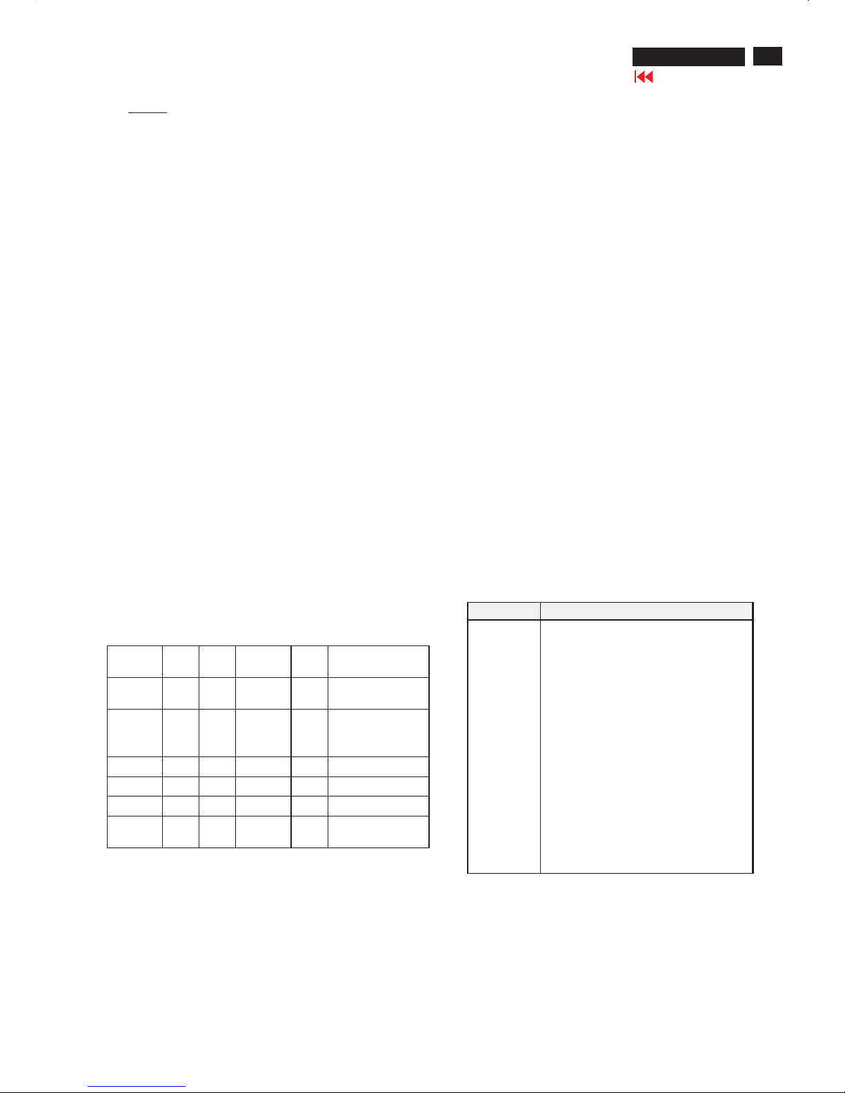
BRIGHT DOT DEFECTS ACCEPTABLE LEVEL
MODEL
190P6 190B6 190S6
1 lit subpixel 0 0 3 or fewer
2 adjacent lit subpixels 0 0 1 or fewer
3 adjacent lit subpixels (one
white pixel)
0 0 0
Distance between two bright
dot defects*
00
25 mm or
more
Total bright dot defects of all
types
0 0 3 or fewer
BLACK DOT DEFECTS ACCEPTABLE LEVEL
MODEL
190P6 190B6 190S6
1 dark subpixel 0 0 5 or fewer
2 adjacent dark subpixels 0 0 2 or fewer
3 adjacent dark subpixels 0 0 0
Distance between two black
dot defects*
00
15 mm or
more
Total black dot defects of all
types
0 0 5 or fewer
TOTAL DOT DEFECTS ACCEPTABLE LEVEL
MODEL
190P6 190B6 190S6
Total bright or black dot
defects of all types
0 0 5 or fewer
Pixel Defect Policy
12
190P6&170P6 LCD
Go to cover page
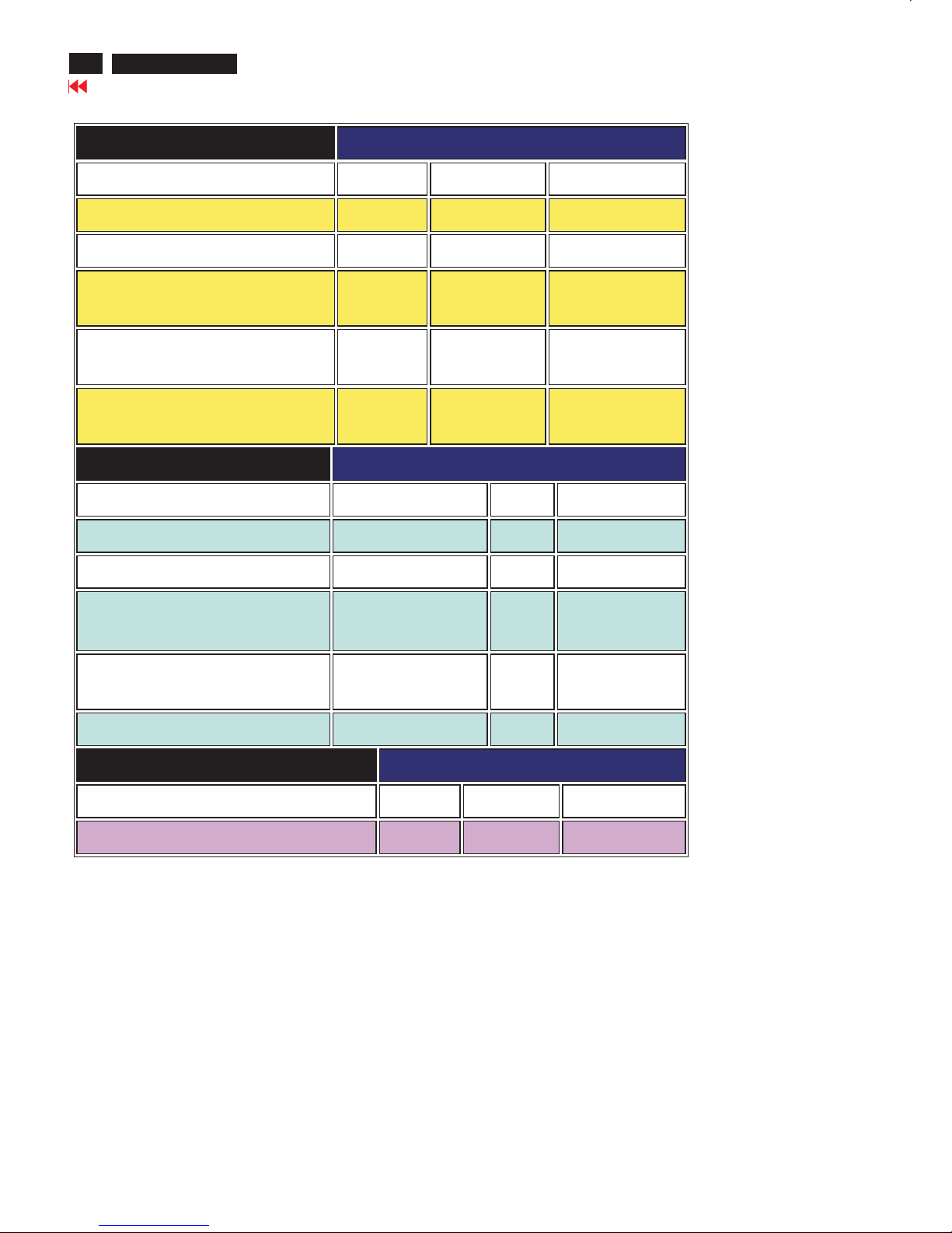
Pixel Defect Policy
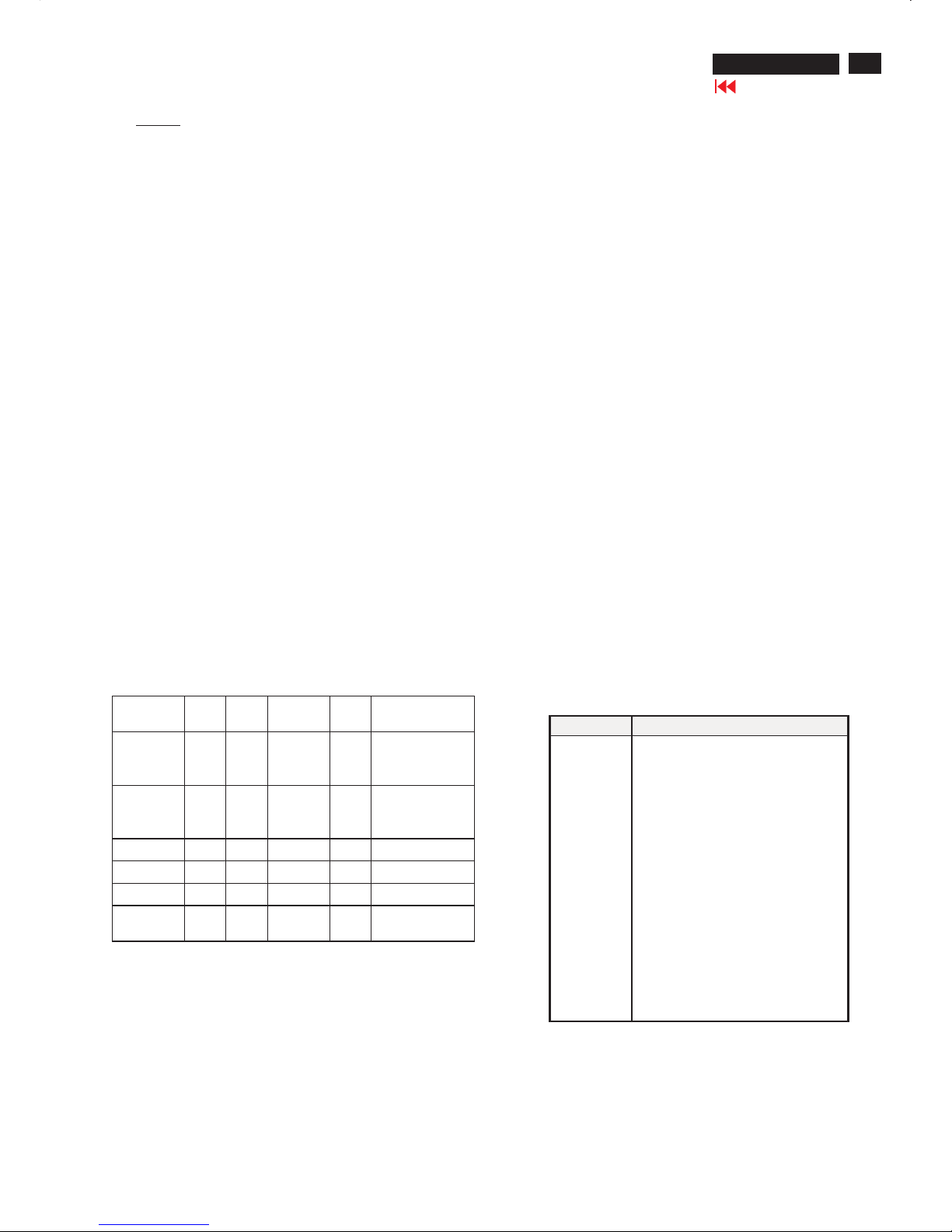
BRIGHT DOT DEFECTS ACCEPTABLE LEVEL
MODEL
170P6 170B6 170S6
1 lit subpixel 0 0 4 or fewer
2 adjacent lit subpixels 0 0 2 or fewer
3 adjacent lit subpixels (one white
pixel)
0 0 0
Distance between two bright dot
defects*
0 0 15 mm or more
Total bright dot defects of all types 0 0 4 or fewer
BLACK DOT DEFECTS ACCEPTABLE LEVEL
MODEL
170P6 170B6 170S6
1 dark subpixel 0 0 4 or fewer
2 adjacent dark subpixels 0 0 2 or fewer
3 adjacent dark subpixels 0 0 0
Distance between two black dot
defects*
0 0 15 mm or more
Total black dot defects of all types 0 0 4 or fewer
TOTAL DOT DEFECTS ACCEPTABLE LEVEL
MODEL
170P6 170B6 170S6
Total bright or black dot defects of all types 0 0 5 or fewer
13
190P6&170P6 LCD
Go to cover page
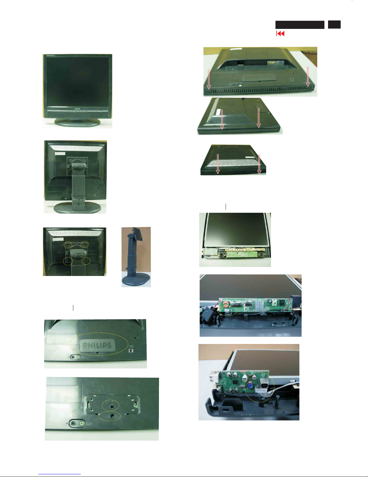
Front View
Back View
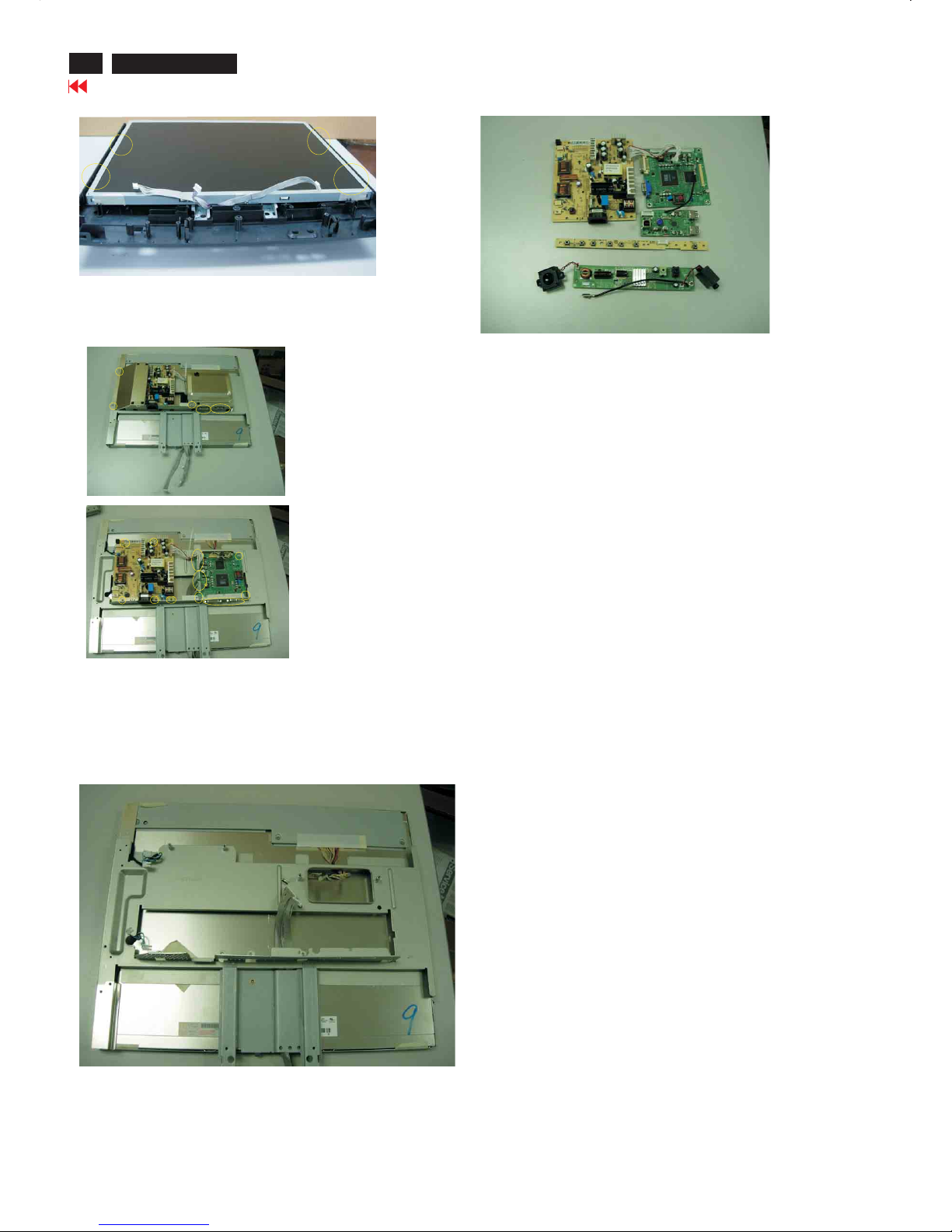
Step1. Remove the base
-Remove the screws as shown in Fig.3 & Fig.4
Step2. Remove the Front Bezel
-Open the cover and remove the one screw as shown in Fig.5, Fig.6
-Use the thin " " screw driver to open the clicks as shown
in Fig.7-9
Step3.Remove the Back cover
- Remove the screws and disconnect the connectors as shown in Fig.10 ,
Fig.11 Fig.12,Fig.13 then remove the AUDIO board, USB board and
control board
-Use the thin " " type screw driver to open the clicks as shown in Fig.10
Fig.4
Fig.5
F
i
g
9
Fig.10
Fig.11
Fig.3
F
i
g
.
8
F
i
g
.
7
Fig.6
Fig.12
Mechanical Instructions
14
190P6&170P6 LCD
Go to cover page
Step 5. Remove the scaler and power board.
- Disconnect the connectors and remove unscrew the screws as shown
in Fig.15
- Remove the scaler and power board as shown in Fig.16 Fig.17
**************************************************************************************
***************************************************************************************
In warranty, it is not allowed to disassembly the LCD panel, even the
backlight unit defect.
Out of warranty, the replacement of backlight units is a correct way
when the defect is caused by backlight (CCFL, Lamp).
Fig.17
Fig.13
Fig.16
Step4. Remove the Matel frame board
- Remove the screws and then remove the metal frame
as shown in Fig.15 Fig.14
Fig.14
Fig.15
Mechanical Instruction
15
190P6&170P6 LCD
Go to cover page
Alignment procedure
1. Turn on the LCD monitor.
2.Turn on the Timing/pattern generator. See Fig.1
Resolution :1280x1024(Use the best resolution)
Timing : H= 31.47KHz V=60Hz
3. Preset LCD color Analyzer CA-110
-Remove the lens protective cover of probe CA-A30.
-Set measuring/viewing selector to measuring position for reset
analyzer.(zero calibration) as Fig.2
- Turn on the color analyzer (CA-110)
-Press 0-CAL button to starting reset analyzer. See Fig.3
Fig. 1
Fig. 2
Cover (black)Cover (black)
Measurement viewing selectorMeasurement viewing selector
Note: after alignment, please reset OSD to user s mode for normal
operation. Otherwise, the monitor won t entering power saving mode
and showing full white picture all the time as no video signal supplied.
To leave factory mode by restart the monitor.
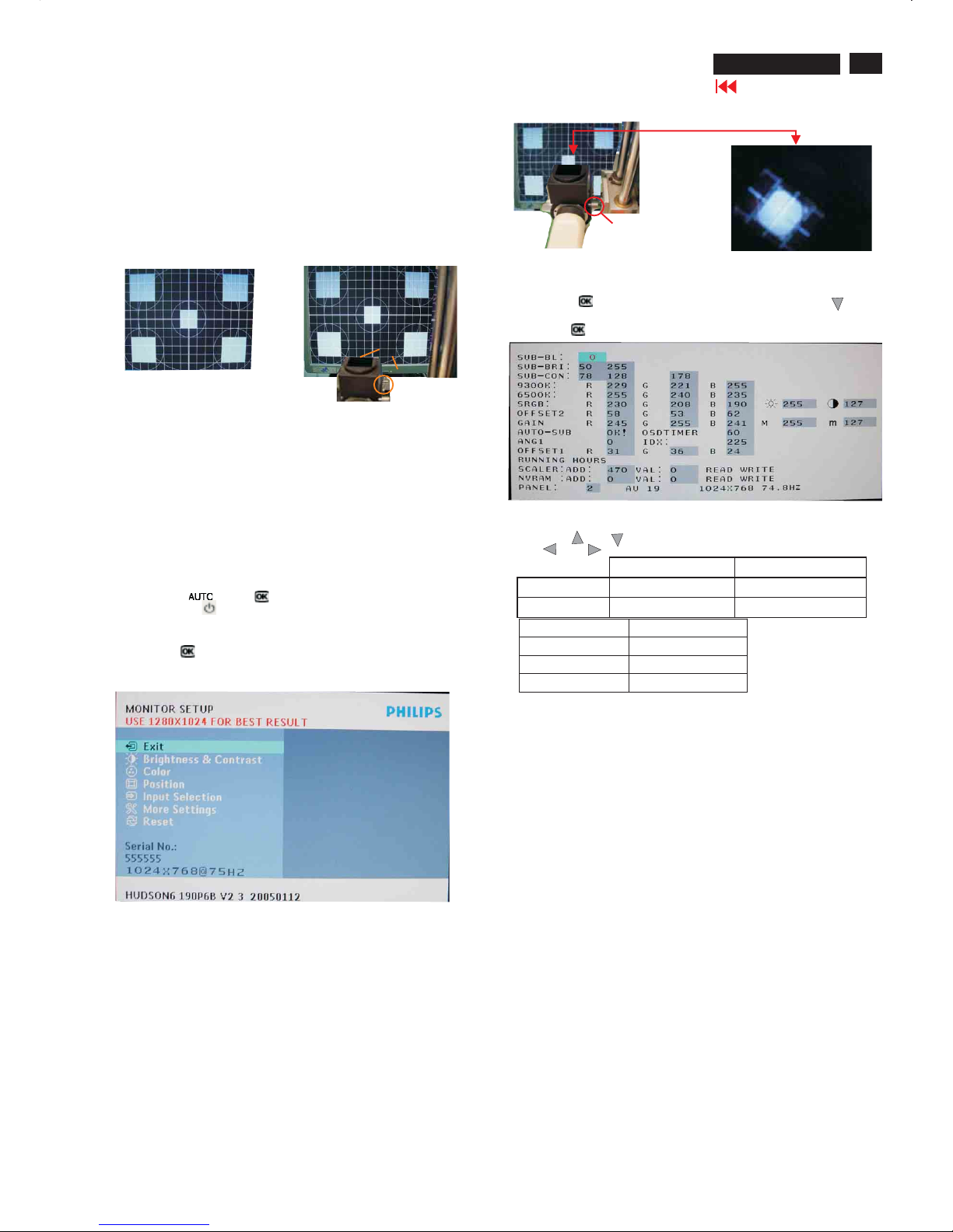
5.Adjust OSD menu to lower position of screen (i.g. adjust V-position to
value " 0 " at submenu of OSD Setting.
6. Setting Brightness and Contrast
-Adjust Brightness to value "90".
-Adjust Contrast to value " 80" .
7. Switch light probe to Viewing position.
8. Move the Lens barrel forward or backward to get clear image as
showninFig.4
9. Switch light probe to Measuring position. It should be able to indicate
Clear imageClear image
Measurement/viewing selectorMeasurement/viewing selector
Alignment hits: 1. R for x value, G for y value,Bfor Y value on the
colour analyzer.
2. If the colour analyzer has been calibrated and preset
colour temperature in it. Please switch to correct
setting in accordance with colour settings.
4. Access Factory Mode
How to get into Factory Mode Menu
Step1:
Turn off monitor.
Step2:
[Push AUTO" "& OK ""buttons at the same time and hold it]
+[Press power ""button untill comes out "Windows screen" ]
=> then release all buttons
Step3:
Press OK ""button, bring up Factory mode indication as shown
in Fig3.
Fig. 3
10. Setting pattern to full white picture
11. Press button, then select factory mode indicator by"" ""
button
12. Press""button to bring up submenu windows as below:
13. Press ""or ""button to select R G B. Change the value by
""or ""key until the X,Y co-ordinates as below
Fig.4
15. EEPROMpresetting(B)
After finishing all the adjustment, set:
Brightness control to 100%
Contrast control to 50%
OSD position at middle of screen
COLORadjusts to 6500K color.
9300°K6500°K
x (center) 0.283 ± 0.020 0.313 ± 0.020
y(center) 0.297 ± 0.020 0.329 ± 0.020
sRGB
x(center) 0.313 ± 0.020
y(center) 0.329 ± 0.020
Ynits 180 ± 10
Display Adjustment
16
190P6&170P6 LCD
Go to cover page
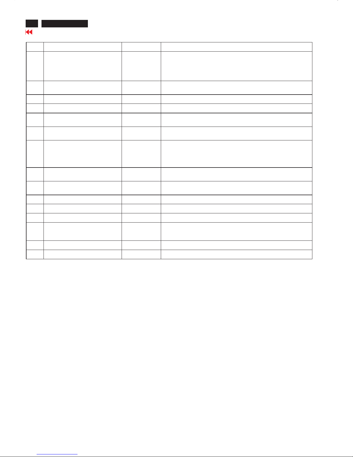
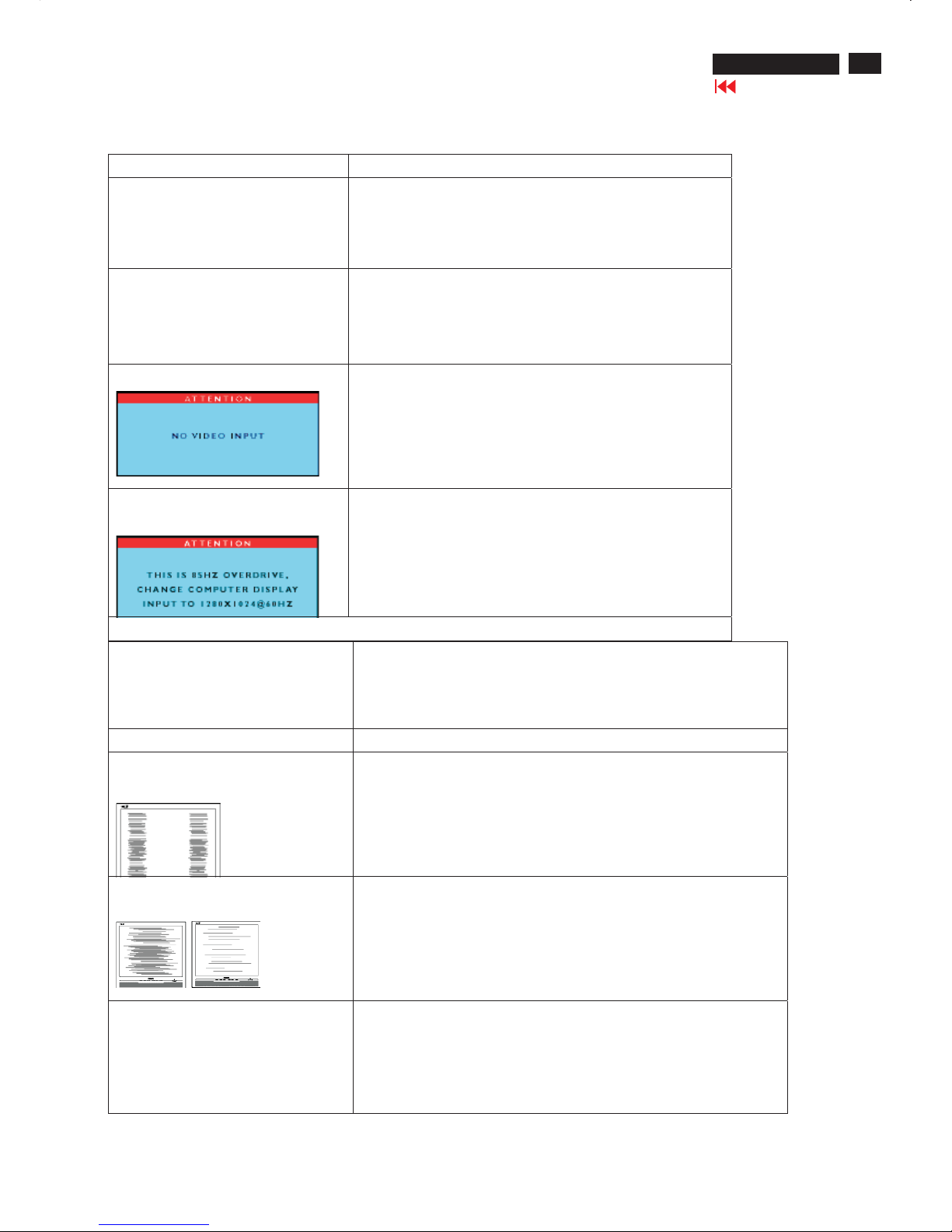
Warning Message Table
Item Attention Signals Display Time Condition
1 CANNOT DISPLAY THIS VIDEO MODE,
CHANGE COMPUTER DISPLAY INPUT
TO 1280X1024 @60Hz
30 mins This warning appears when the input signal from your computer is not in a standard
video mode or is out of the monit or s scanning range. After 30 mins, monitor enters
sleeping mode.
2 NO VIDEO INPUT 30mins This message appears when there is no signal input but with cable while AC or DC
power on. After 30 mins, monitor enters sleeping mode
3 CHECK CABLE CONNECTION 30mins This message appears when a signal cable is disconnected while monitor is working,
after 30 mins, monitor enters sleeping mode
4 ENTERING SLEEP MODE 3 secs This message appears when monitor is about to enter power saving mode
5 WAITING FOR AUTOMATIC
ADJUSTMENT
Till auto adjustment
finished
This message displayed when the auto adjustment button is pressed. It dis appears
when automatic adjustments are completed
6 USE 1280X1024 FOR BEST RESULT On top of OSD
main menu
The message will show up at the top of the OSD main menu in red color when the input
resolution is not the 1280x1024.
7 OSD MAIN CONTROLS LOCKED 3 secs / or Till
OSD MAIN
CONTROLS
UNLOCKED
appear
This message will appear 3 seconds to indicate the OSD MAIN CONTROLS status
when to lock or un-lock it by pressing MENU(OK) button for more than 10 seconds
while there is video input from PC. This function provides the alternative that user can
lock all the OSD main control in case user don t want the FOS performance setting to
be changed, for ins tance, during
Commercial exhibition
8 OSD MAIN CONTROLS UNLOCKED 3 secs This message will appear 3 seconds to indicate the OSD MAIN CONTROLS status
when to un-lock it by pressing MENU(OK) button for more than 10 seconds while
there is video input from PC
9 THIS IS 85HZ OVERSCAN, CHANGE
COMPUTER DISPLAY INPUT TO
1280X1024@60HZ
10 mins This message will appear 5 seconds in every 60 seconds for 10 minutes when the input
of PC video timing is at 85Hz mode. Remark: AUTO is still functional in this mode
10 the window of " MONITOR SETUP" 60 secs This message will appear when the OK button is pressed.
11 the window of "BRIGHTNESS" 60 secs This message will appear when the BRIGHTNESS button is pressed.
12 SELECTED INPUT NOT AVAILABLE 3 secs When just one input (analog or digital), press input switch or hot key, then after
show this warning message 3 sec, return to origi nal input
13 SECURITY PROTECTED, THIS
MONITOR IS GO ING TO ENTER POWER
SAVING MODE IN 15 SECONDS
15 secs This warning appears when the security was set ON and someone
takes out from the cli ent PC
14 ENTER POWER SAVING MODE 1 min This warning appears when Asset management Server sends power saving command
to client PC
15 the window of VOLUME 60 secs This message will appear when the VOLUME button is pressed.
"
"
"
"
""
""
""
""
""
'
17
190P6&170P6 LCD
Go to cover page
Trouble shooting
CommonProblems
Display positionisincorrect
· Press the Auto button.
· Adjustthe image positionusingthe HorizontalPosition and/or Vertical
PositioninOSDMain Controls.
Image vibrates on the screenCheck that the signal cable is properly connected to thegraphicsboard or PC.
Verticalflicker appears
· Press the Auto button.
· Eliminate theverticalbarsusingthe More Settings ofPhase/Clockin
OSD Main Controls.
Horizontalflicker appears
· Press the Auto button.
· Eliminate theverticalbarsusingthe More Settings ofPhase/Clockin
OSD Main Controls.
The screenistoo brightortoodark
· Adjustthecontrastand brightness onOSDMain Controls. (The
backlightof the LCD monitor has a fixedlife span. When the screen
becomesdark or begins to flicker, pleasecontact your dealer).
Havingthis problem Check these items
No Picture
(Power LED not lit)
· Make sure thepower cordispluggedinto thepower outlet
and into the back of the monitor.
· First, ensure that thepower button on the frontof the monitor
is in the OFF position, then press ittothe ON position.
No Picture
(Power LED is amber or yellow)
· Make sure thecomputer is turned on.
· Make sure the signal cable is properly connected to your
computer.
· Check to see if the monitor cable hasbentpins.
Screen
· Make sure the monitor cable is properly connected to your
computer.(Alsorefer to the QuickSet-UpGuide).
· Check to see if the monitor cable hasbentpins.
· Make sure thecomputer is turned on.
Screensays
· Make sure theverticalsyncofinput signaliswithin therange
of56~75Hz.
· Change therefresh rate to 56~75Hz within10minutes.
· Re-power onmonitor to start over again if youfailed to
change therefresh rate within 10 minutes.
Imaging Problems

18
190P6&170P6 LCD
Go to cover page
Trouble shooting
An after-image appears
· If an image remains on the screen for an extended period of time, it
may be imprinted in the screen and leave an after-image. This usually
disappears after a few hours
An after-image remains after the power has
been turned off.
· This is characteristic of liquid crystal and is not caused by a
malfunction or deterioration of the liquid crystal. The after-image will
disappear after a peroid of time.
Green, red, blue, dark, and white dots
remains
The remaining dots are normal characteristic of the liquid crystal used in today’s
technology
19
190P6&170P6 LCD
Go to cover page
Electrical instructions(190P6)
20
190P6&170P6 LCD
Go to cover page
Electrical instructions(190P6)
4.3 Adjustment of WHITE-D (B)
Apply a 1280*1024 / 60Hz signal with white pattern, set brightness
to 100%, and contrast to 50%. Adjust the R, G, B Sub-Gain, for the
screen center, the 1931 CIE chromaticity (X, Y) co-ordinates shall
be;
Use Minolta CA-110 for color coordinates and luminance check.
Luminance is > 200 Nits in the center of the screen when
brightness is set to 100% and contrast is set to 50%.
4.4 Adjustment of sRGB
Apply a 1280*1024 / 60Hz signal with white pattern, set brightness
to 100%, and contrast to 50%. Adjust the R, G, B Sub-Gain,
for the screen center, the 1931 CIE chromaticity
(X, Y) co-ordinates shall be;
sRGB
x(center) 0.313 ± 0.020
y(center) 0.329 ± 0.020
Ynits 180 ± 10
4.5 EEPROM presetting (B)
After finishing all the adjustment, set:
Brightness to 100%
Contrast to 50%
OSD position at middle of screen
COLOR ADJUST to 6500K color temperature.
Stand-Alone set to Off
Smart Bright set to Off
9300°K 6500°K
x (center) 0.283 ± 0.020 0.313 ± 0.020
y (center) 0.297 ± 0.020 0.329 ± 0.020

21
190P6&170P6 LCD
Go to cover page
Electrical instructions(170P6)
1. General points
1.1 During thetestandmeasuring, supply a distortion free AC mains
voltagetothe apparatus via an isolated transformer with low
internal resistance.
1.2 All measurements mentionedhereafter are carried out at a normal
mains voltage (90 - 132 VAC for USA version, 195 -264VACfor
EUROPEAN version, or 90 -264 VAC for the model withfull range
power supply, unless otherwise stated.
)
1.3 All voltages are to be measured or appliedwith respect to ground,
unless otherwise stated.
Note:do not use heat-sink as ground.
1.4 Thetesthas to be done on a complete set including LCD panel
after 30 minutes warm-up at least in a roomwith temperature of
25 +/- 5 degree C.
1.5 All values mentioned in these test instruction are only applicable of
a well aligned apparatus,with correct signal.
1.6 Theletterssymbols (B)an
d (S)placedbehind the test instruction
denotes
(B): carried out 100% inspection at assembly line
(S): carried out test by sampling
1.7 The white balance (color temperature) has to betested in subdued
lighted room.
1.8 Repetitive power on / off cycle are allowed except it shouldbe
avoidedwithin6sec.
2. Input signal
2.1 Signal type
2.1.1 Video signal input
Signal source: pattern generator format (refer to spec)
Reference generator:QuantumData 802G
The input signals can be applied in two different modes:
1).VESA Analog
Thevideo input consists of red, green, andblue signals.Thevideo
signals are analog levels,where 0V correspondstoblack and 700mV
is the maximum signal amplitude.Input impe
dance of video pins is
75 ohm +/- 1%.
2).Intel DVI Digital
Input signal:Four channel TMDS signals
2.1.2 Sync signal input
Thecapability of sync signal inputs shall include separate sync,
composite sync and sync on green. input impedance:2k2ohms
The signals are defined as follow:
Separate sync TTL level, Positive/Negative
Composite sync TTL level, Positive/Negative
Sync on green
H-sync TTL level, Positive/Negative
Signal source: pattern generator format (refer to spec)
Reference generator:QuantumData 802G
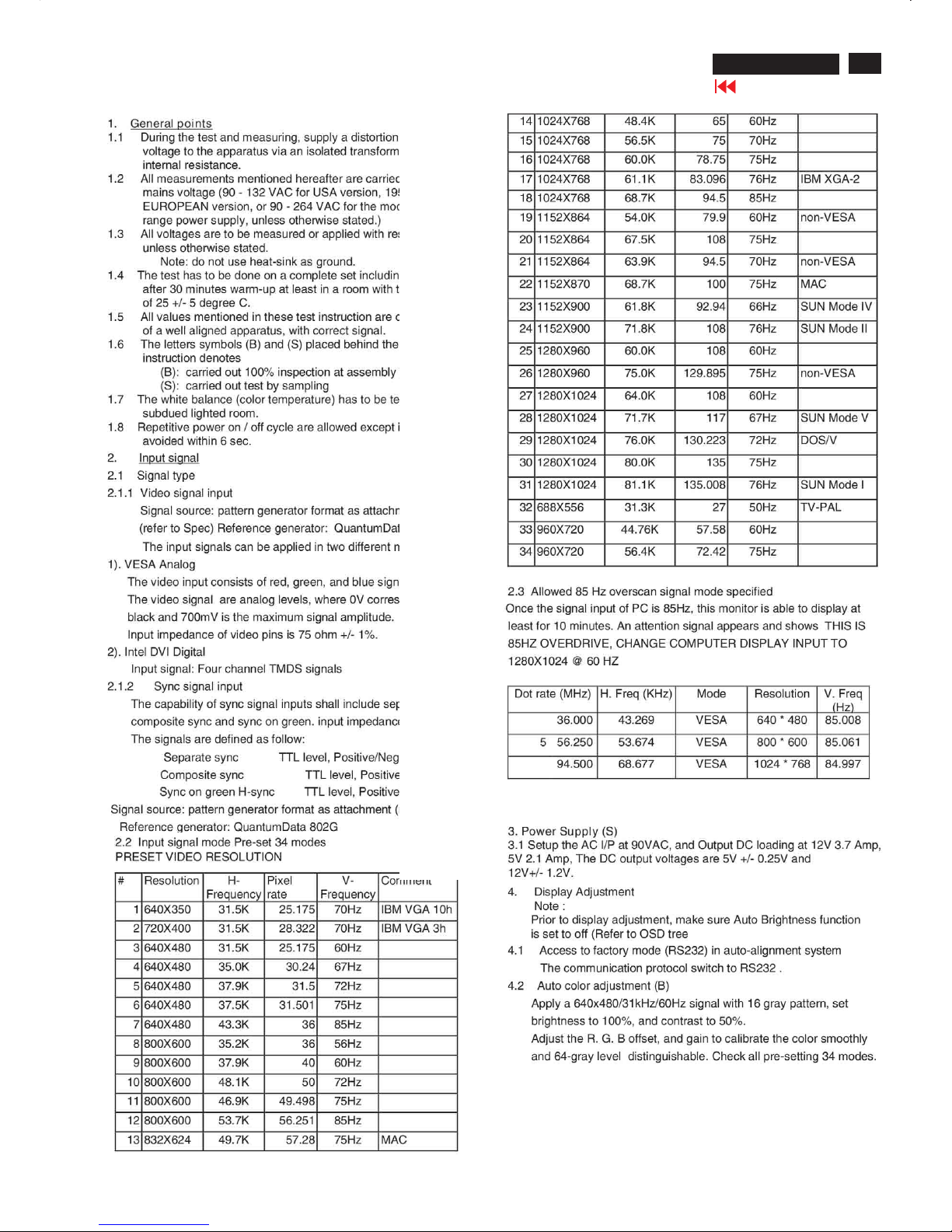
2.2 Input signal mode
Pre-set 34 modes
PRESETVIDEORESOLUTION
#Resolution H-
Frequency
Pixel
rate
V-
Frequency
Comment
1640X350 31.5K 25.175 70Hz IBM VGA 10h
2 720X400 31.5K 28.322 70Hz IBM VGA3h
3 640X480 31.5K 25.175 60Hz
4 640X480 35.0K30.24 67Hz
5 640X480 37.9K 31.5 72Hz
6640X480 37.5K 31.501 75Hz
7640X480 43.3K 36 85Hz
8800X600 35.2K 36 56Hz
9800X600 37.9K 4060Hz
10 800X600 48.1K5072Hz
11 800X600 46.9K 49.498 75Hz
12800X600 53.7K56.251 85Hz
13 832X624 49.7K57.28 75Hz MAC
14 1024X768 48.4K 65 60Hz
15 1024X76856.5K 75 70Hz
16 1024X768 60.0K 78.75 75Hz
17 1024X768 61.1K 83.09676Hz IBM XGA-2
18 1024X768 68.7K 94.5 85Hz
19 1152X864 54.0K 79.9 60Hz non-VESA
201152X864 67.5K 108 75Hz
211152X864 63.9K 94.5 70Hz non-VESA
22 1152X870 68.7K 100 75Hz MAC
23 1152X900 61.8K 92.94 66Hz SUN Mode IV
24 1152X900 71.8K 108 76Hz SUN Mode II
25 1280X960 60.0K 108 60Hz
261280X960 75.0K 129.89575Hz non-VESA
271280X1024 64.0K 108 60Hz
28 1280X1024 71.7K 117 67Hz SUN Mode V
29 1280X1024 76.0K 130.22372Hz DOS/V
301280X1024 80.0K 135 75Hz
311280X1024 81.1K 135.00876Hz SUN Mode I
32 688X556 31.3K 27 50Hz TV-PAL
33 960X720 44.76K57.58 60Hz
34 960X720 56.4K 72.42 75Hz
2.3 Allowed85Hzoverscan signal mode specified
Once the signal input of PC is 85Hz, this monitor is able to display at
least for10 minutes.An attention signal appears and shows THIS
IS 85HZ OVERDRIVE, CHANGE COMPUTERDISPLAY INPUT TO
1280X1024 @ 60 HZ
Dot rate (MHz) H.
Freq (KHz)
Mode Resolution V.
Freq (Hz)
36.000 43.269VESA 640 *480 85.008
556.250 53.674VESA 800 * 600 85.061
94.500 68.677 VESA 1024 * 768 84.997
3. Power Supply (S)
3.1 Setup the AC I/Pat90VAC, andOutput DC loading at 12V 3.7 Amp,
5V 2.1 Amp,The DC output voltages are 5V +/- 0.25V and 12V+/- 1.2V.
22
190P6&170P6 LCD
Go to cover page
Electrical instructions(170P6)
4. Display Adjustment
Note :
Prior to display adjustment, make sure Auto Brightness function
is set to off (Refer to OSD tree)
4.1 Access to factory mode (RS232) in auto-alignment system
The communication protocol switch to RS232 .
4.2 Auto color adjustment (B)
Apply a 640x480/31kHz/60Hz signal with 16 gray pattern,
set brightness to 100%, and contrast to 50%.
Adjust the R. G. B offset, and gain to calibrate the color
smoothly and 64-gray level distinguishable.
Check all pre-setting 34 modes.
4.3 Adjustment of WHITE-D (B)
Apply a 1280*1024 / 60Hz signal with white pattern, set
brightness to 100%, and contrast to 50%. Adjust the
R, G, B Sub-Gain, for the screen center, the 1931 CIE
chromaticity (X, Y) co-ordinates shall be;
Use Minolta CA-110 for color coordinates and luminance check.
Luminance is > 200 Nits in the center of the screen when
brightness is set to 100% and contrast is set to 50%.
4.4 Adjustment of sRGB
Apply a 1280*1024 / 60Hz signal with white pattern, set brightness
to 100%, and contrast to 50%. Adjust the R, G, B Sub-Gain, for
the screen center, the 1931 CIE
chromaticity (X, Y) co-ordinates shall be;
sRGB
x(center) 0.313 ± 0.020
y(center) 0.329 ± 0.020
Ynits 180 ± 10
4.5 EEPROM presetting (B)
After finishing all the adjustment, set:
Brightness to 100%
Contrast to 50%
OSD position at middle of screen
COLOR ADJUST to 6500K color temperature
Stand-Alone set to Off
Smart Bright set to Off
9300°K 6500°K
x (center) 0.283 ± 0.020 0.313 ± 0.020
y (center) 0.297 ± 0.020 0.329 ± 0.020
23
190P6&170P6 LCD
Go to cover page
LightFrame DR
TM
LightFrameTM Digital Reality(LightFrameTM DR)for Windows
Introduction
Philips LightFrameTM DR feature enrichesyour photo and video
experience with preset modes idealfor your favorite applications:
Internet,TV/video viewing, photos and gaming.The LightFrameTM DR
engine optimiz
esbrightness, sharpness, contrast, color,JPG noise for
photos and skin tone for videos.
Installation
Firstthingsfirst:Philips LightFrame
TM
DR only works with latest Philips
LCD Monitor which issepcially builttousethissoftware.That is
LightFrame
TM
DR can only work on 170X5,190X5 or 170P6/190P6 or
later version LCDmonitor.Earlier Philips monitors or other
manufacturers monitorswill not workwith this picture enhancement
software.You can identify compatible Philips monitorsbythe
LightFrame logo on the fronto
f the monitor.
LightFrame
TM
DR works with true Windows-based programs and
DOS-based programs that operate in a Windows environment.It does
not workwith DOS-based programs operatingonly in aDOS
environment.
Tocontrol the LightFrame
TM
DR feature inyourmonitor,you'll wantinstall
the LightFrame
TM
DR applicationfound on thisCD-ROM.
Toinstall LightFrame
TM
DR, place the CDinyour CD-ROM drive.
When the CDmenu appears onyour screen,
1) select preferredlanguage
2) select modelnumber (17P6 or 190P6)
3) click on Install LightFrame
TM
Digital Reality.
Follow the on-screen prompts to properly install the program.The software
checks to see ifyou have a compatiblemonitor.You must agree to the
licenseterms in order to install the software.
After installation, the LightFrame
TM
DR shortcuticon automatically appears
at your desktop, click it to load the controlbar onscreen.
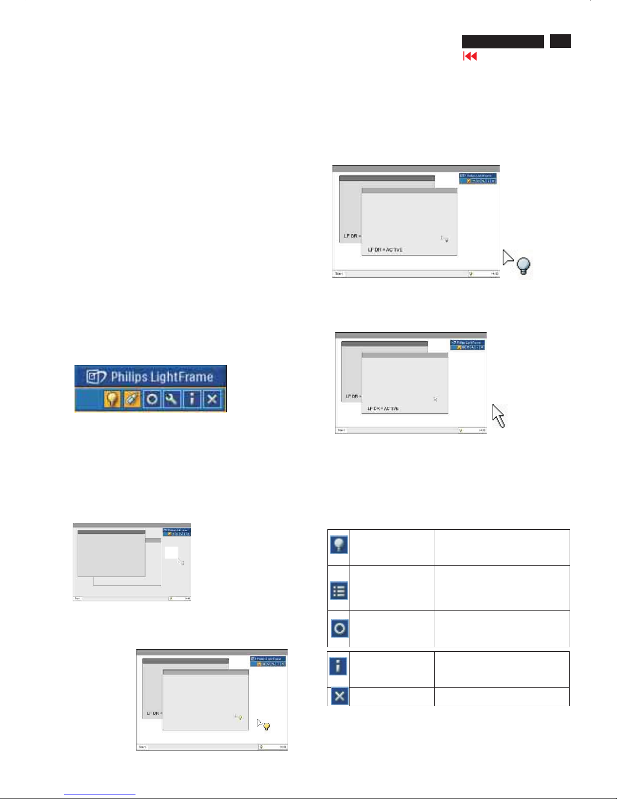
Use Tips
1. Cursor with a yellow light bulb versus a blue light bulb
Yourmouse pointer takes the shape of a light bulb to indicate that
LightFrame
TM
DR is ready to activate or deactivate a target window
that contains photos, videos or other content that canbeenhanced.
Ayellowlight bulb means that you are movingoverawindowwhere
LightFrame
TM
DR canbeactivated. Click on the window to activate
enhancement.Ablue light bulb appearswhen movingoveran
activatedwindow. Click on the window to de-activate LightFrame
TM
DR.
Cursor examples
Here is a listof LightFrame
TM
DR cursors.
This is the defaultcursor displayedwhenyou move over a
non-LightFrame
TM
DR enhancedwindow or area.Clickingand
draggingthis cursor over a window or area activates LightFrame
TM
DR
enhancement.
Yourcursor becomes a yellowlight bulb when it passes over a
non-active window to indicate that LightFrame
TM
DR canbe
activated in the selectedwindow. Click to activate LightFrame
TM
DR
in the selectedwindow. To activate LightFrame
TM
DR simultaneously
in atotal ofuptoeightwindows, click on the selectedwindows
one-by-one whilepressingtheShift key.
Yourcursor becomes a blue light bulb when it passes over an act ive
LightFrame
TM
DR window. C lick to deactivate LightFrameTMDR in the
selectedwindow.
The normal cursor is restored after you click on atargetwithoutpressing
the shift key or after youdrag a rectangle.
2. LightFrame
TM
DR controlbar
The LightFrame
TM
DR controlbar appears at the top ofscreen after any
LightFrame
TM
DR function is activated.
The controlbar is another upgradethathelpsyou run all LightFrame
TM
Digital Reality's neat,newfeatures. The illustrationbelowdescribes the
tasks each button performs.
To drag the controlbar to any preferred area ofyour screen, leftclick the
LightFrame
TM
DR logo.(See examplesbelow) This area isnot a button.
Activate or deactivate
LightFrameTM DR
icon
Turns LightFrameTM DR on and off.
When LightFrameTM DR is active in
a selectedwindow, the icon changes
from bluetoyellow.
Activate or
deactivate the
modemenu icon
The defaultmodemenu icon
appearswhennomodeisselected.
Whenyouselect the photo,Internet
or other mode, the iconfor the
selected mode appears.
Deactivate all
LightFrameTM DR
windows icon
Deactivates all LightFrameTM DR
windows. Thisfunction is only visible
when LightFrameTM DR windows
are active.
InfomodeiconActivates and deactivates the Info
mode,which provides information
abouttoolbar and menu items as
well as access to Help files.
Exit iconClick to exit the LightFrameTM DR
controlbar
24
190P6&170P6 LCD
Go to cover page
LightFrame DR
TM
Properties icon Provides access to the Properties
menu, whichincludes these options:
LightFrameTM DRautostart:Yes/no
Position: LightFrameTM DR Always
on top
Warningmessages: On/off
Target selection: Automatic/manual
Monitor selection: Chos
eamongtwo
monitors connected to the same PC
Place LightFrameTM DRicon in the
taskbar:Yes/no
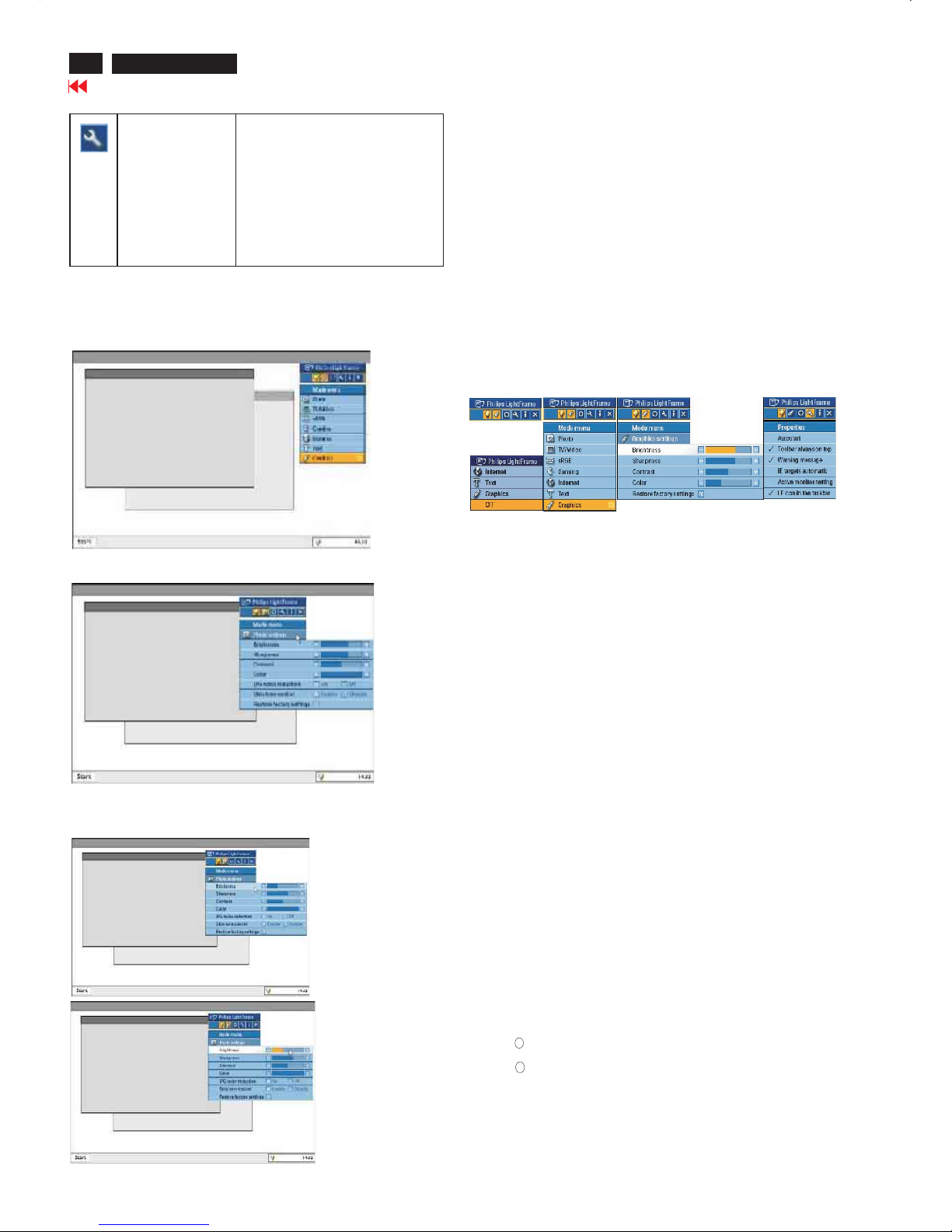
3. Optimizing LightFrameTM DR settings
Here's how tooptimize LightFrameTM DR settings toyour personal
preferences:
1.Select your desired mode fromthemode Menu. Click toopen the mode.
The settings menu
2.
3.Change settingsbypullingthecolor bar or pressi ngtheplus (+) or
minus (-) button to moveincrementally to the desiredlevels.
When you're finished, click on the Modeicon to exit the menu.
4. LightFrameTM Hot Key
The LightFrameTM Hot Key islocated at front of LightFrameTM DR
monitor.
The blue LED isonwhenLightFrameTM is activated and off when
the feature isdeactivated. A touch on the Hot K
eyquickly provides
full screen enhancementinyour choice of the Internet,Photoor
Video-TV mode.
Whenyoutouchthefront button, a small OSD window opens on
your screendirectly abovethebutton location.
Usethisscreen toselectthebe
st full screen mode forthe
application you're working with.Press continuously on the Hot Key
toscroll through the available options.
1) WhenyoutouchtheLightFrameTM Hot Key, anOSDwindow
opens. Touchthebutton continually toscroll amongtheavailable
Internet,Phot
o and Video-TV modes. As amode becomes
available for selection, itscolor changesfrom bluetoyellow.
Once you reachthedesired mode, remove your finger from
the Hot Key. A fter three seconds, the mode you have selec
ted
will be confirmed and the OSD window will automatically close.
2) TouchtheLightFrameTMDR Hot Keyfor three seconds to enter
the LightFrame
TM
demo mode.Toexit the demonstration mode,press
the hot key again.
5. Language
While Englishis the default language of LightFrame
TM
DR,Dutch,
French,German, Italian, Portuguese,Spanish,SimplifiedChinese,
TraditionalChineseand Korean are supported. LightFrame
TM
DR will
detectthelanguage of computer system OS and selectthelanguage
automatically.
Notes
Philips LightFrame
TM
DR only works with monitorsspecially builttouse
thissoftware.IfLightFrame
TM
DR detects that yourmonitorisnot
LightFrame
TM
DR-compatible, amessage appearsonthe monitor screen.
If you see this message,youcan abort or continuetheinstallation;
however, ifyoucontinuetheinstallation, LightFrame
TM
DR will probably
not workonthe monitor.
How touse LightFrame
TM
DR
After installation,LightFrame
TM
DR shortcuticon appearsonyour screen
whenever the computer isstarted.
To learn more about using LightFrame
TM
Digital Reality, pleaserefer to
the help information, whichis availableafter installation.
Com patibility
Thisversion of LightFrame
TM
DRiscompatible with:
Windows XP
Windows 2000 ProfessionalEdition with Service Pack 2
How to downloadyour upgradedLF DR Ins tallation file
Visit http://www.philips.com/support
R
R
25
190P6&170P6 LCD
Go to cover page
All units that are returned for service or repair must pass the
original manufactures safety tests. Safety testing requires both
and testing.Hipot Ground Continuity
HI-POT TEST INSTRUCTION
1.Application requirements
2.
1.1 All mains operated products must pass the Hi-Pot test as
described in this instruction.
1.2 This test must be performed again after the covers have
been refitted following the repair, inspection or modification
of the product.
2.1 Connecting conditions
2.1.1 The test specified must be applied between the parallel-
blade plug of the mainscord and all accessible metal
parts of the product.
2.1.2 Before carrying out the test, reliable conductive
connections must be ensured and thereafter be
maintained throughout the test period.
2.1.3 The mains switch(es) must be in the "ON" position.
2.2 Test Requirements
All products should be HiPot and Ground Continuity tested as
follows:
Test 2820VDC 1700VDC Test current:
voltage (2000VAC) (1200VAC) 25A,AC
Test time:
Test time 3 seconds 1 second 3 seconds(min.)
(min.) Resistance
required:
Trip set at 100 uA 5 mA <=0.09+Rohm,
current for Max. R is the
(Tester) limitation; set resistance of
at 0.1 uA for the mains cord.
Min. Limitation
Ramp set at 2
time seconds
(Tester)
Test method
Condition HiPot Test for HiPot Test for Ground Continuity
products where products where Test requirement
the mains input the mains input is
range is Full 110V AC(USA
range(or 220V type)
AC)
2.2.1 The minimum test duration for Quality Control Inspector
must be 1 minute.
2.2.2 The test voltage must be maintained within the specified
voltage + 5%.
2.2.3 There must be no breakdown during the test.
2.2.4 The grounding blade or pin of mains plug must be
conducted with accessible metal parts.
3. Equipments and Connection
3.1. Equipments
For example :
- ChenHwa 9032 PROGRAMMABLE AUTO SAFETY
TESTER
- ChenHwa 510B Digital Grounding Continuity Tester
- ChenHwa 901 (AC Hi-pot test), 902 (AC, DC Hi-pot test)
Withstanding Tester
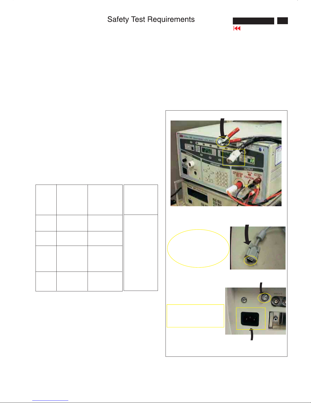
3.2. Connection
4. Recording
Hipot and Ground Continuity testing records have to be kept
for a period of 10 years.
* Turn on the power switch of monitor before Hipot and
Ground Continuity testing.
Connect the "video cable"
or "grounding screw"
to the CLIP on your tester.
Video cable
(Rear view of monitor)
Connect the power cord
to the monitor.
Grounding screw
Power outlet
(ChenHwa 9032 tester)
Clip
Clip
26
190P6&170P6 LCD
DDC Instructions
To Monitor
D-sub/DVI cable
DC 8~12V
To Printer port
Power
indicator
To Monitor
D-sub cable
DC 8~12V
To Printer port
Power
indicator
General
DDC Data Re-programming
Analog DDC IC, & EEPROM
Additional information
In case the DDC data memory IC or main EEPROM which storage all
factory settings were replaced due to a defect, the serial numbers have
to be re-programmed" ".
It is advised to re-soldered DDC IC and main EEPROM from the old
board onto the new board if circuit board have been replaced, in this case
the DDC data does not need to be re-programmed.
Additional information about DDC (Display Data Channel) may be
obtained from Video Electronics Standards Association (VESA).
Extended Display Identification Data(EDID) information may be also
obtained from VESA.
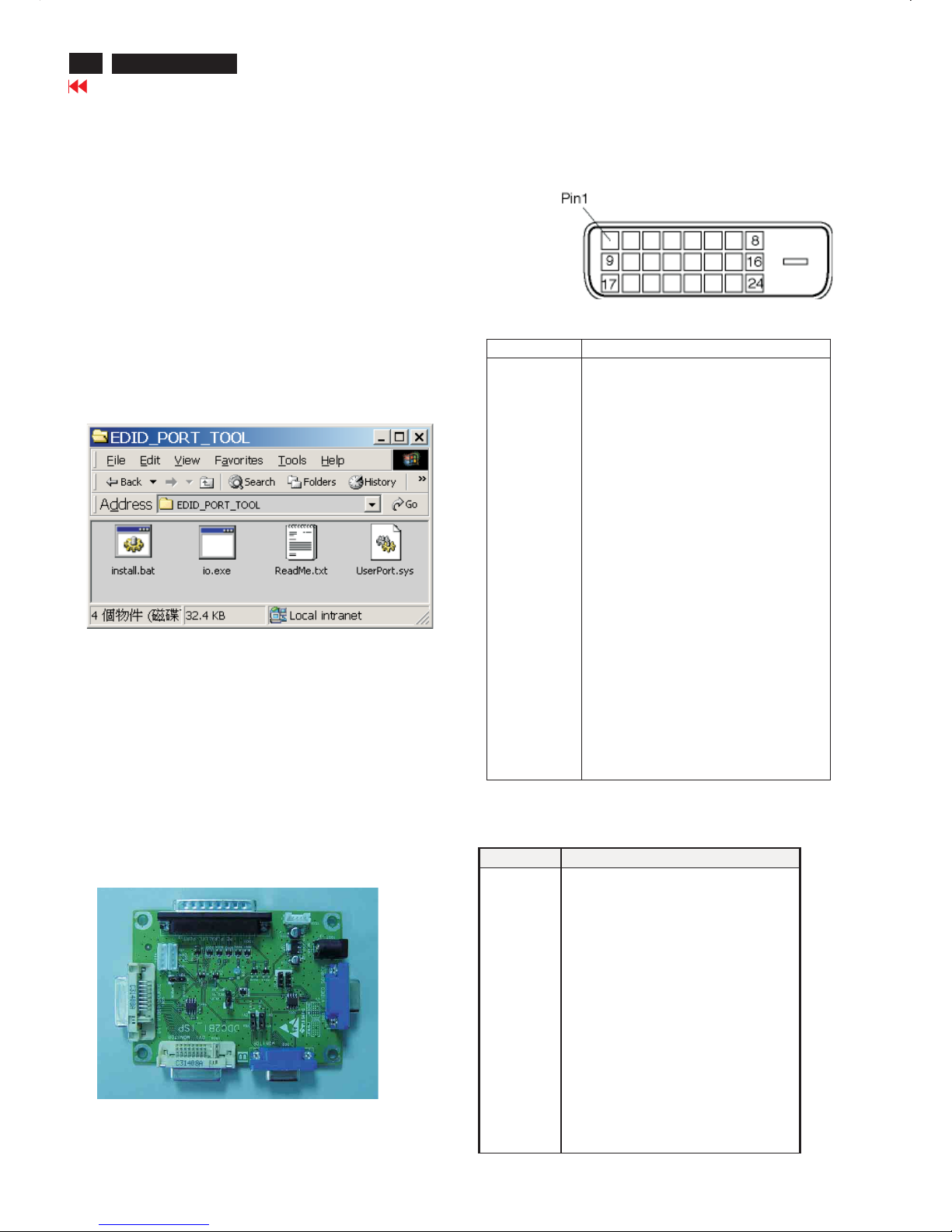
1. An i486 (or above) personal computer or compatible.
2. Microsoft operation system Windows 95/98 .
Y o Install the EDID_PORT_Tool under Win2000/XP . As
Fig. 1 .
A. Cody the "UserPort.sys" to C:\WINNT\system32\drivers(win2000)
C:\WINDOWS\system32\drivers(winXP)
B. Running " io.exe" everytime, Before you start to programming
edid data .
4. DDC 2BI-ISP TOOL:
Inclusion :
A. DDC2BI-ISP TOOL(3138 106 10396) x1 (as Fig. 2)
B. Printer cable x1
c. (D-Sub) to (D-Sub) cable x2
D. D-SUB to DVI cable X1
Note: The EDID46.EXE is a windows-based program, which cannot
beruninMS-DOS.
System and equipment requirements
ou have t
3. EDID46 Release For writing block4.EXE program .
Fig. 2Fig. 2
Fig. 1Fig. 1
Pin Assignment
The digital only connector contains 24 signal contacts organized in
three rows of eight contacts. Signal pin assignments are listed in the
following table:
Fig. 3Fig. 3
Fig. 4Fig. 4
Pin No. Description
1 T.M.D.S. data2-
2 T.M.D.S. data2+
3 T.M.D.S. data2 shield
4 No Connect
5 No Connect
6 DDC clock
7 DDC data
8 No Connect
9 T.M.D.S. data1-
10 T.M.D.S. data1+
11 T.M.D.S. data1 shield
12 No Connect
13 No Connect
14 +5V Power
15 Ground (for +5V) – Cable detect
16 Hot plug detect
17 T.M.D.S. data0-
18 T.M.D.S. data0+
19 T.M.D.S. data0 shield
20 No Connect
21 No Connect
22 T.M.D.S clock shield
23 T.M.D.S. clock+
24 T.M.D.S. clock-
Input analog D-sub connector pin assignment
PIN No. SIGNAL
1 Red video input
2 Green video input / sync on green
3 Blue video input
4 GND
5 GND
6 Red video GND
7Green video GND
8 Blue video GND
9 DDC +3.3V or +5V
10 Logic GND - Cable detect
11 GND
12 Serial data line (SDA)
13 H-sync / H+V
14 V-sync
15 Data clock line (SCL)
Go to cover page
27
190P6&170P6 LCD
DDC Instructions
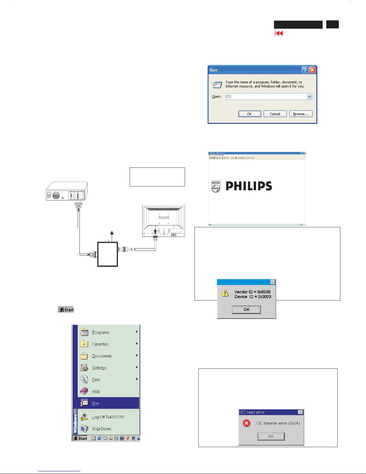
Step 3: Installation of EDID45.EXE
Method 1: Start on DDC program
Start Microsoft Windows.
1. The Program"EDID45.EXE" in service manual cd-rom be copyed to C:\ .
2. Click , choose Run at start menu of Windows as shown
In Fig. 6.
Fig. 6
4. Click button. The main menu appears (as shown in Fig. 8).OK
This is for initialize alignment box.
Fig. 8
Fig. 7
Fig. 9
Note 1: If the connection is improper, you will see the following error
message (as shown in Fig. 9) before entering the main menu.
Meanwhile, the (read EDID) function will be disable. At this time,
please make sure all cables are connected correctly and fixedly,
and the procedure has been performed properly.
3. At the submenu, type the letter of your computer's hard disk drive
followed by :EDID45 (for example, C:\EDID45, as shown in Fig. 7).
Note 2: During the loading, EDID45 will verify the EDID data which just
loaded from monitor before proceed any further function, once the
data structure of EDID can not be recognized, the following error
message will appear on the screen as below. Please
confirm following steps to avoid this message.
1. The data structure of EDID was incorrect.
2. DDC IC that you are trying to load data is empty.
3. Wrong communication channel has set at configuration setup
windows.
1
Configuration and procedure
There are 3 chips contained OSD string, serial number..etc
on the circuit board, main EEPROM which storage all factory settings,OSD
string. DDC IC which storage 128byte EDID data(serial number ..etc.).
Following descirptions are the connection and procedure for Analog
/Digital and main EEPROM can be re-programmed along with
Analog/Digital IC by enable factory memory data write function on the
DDC program (EDID45.EXE).
Initialize alignment box
In order to avoid that monitor entering power saving mode due
to sync will cut off by alignment box, it is necessary to initialize
alignment box before running programming software
(EDID45.EXE). Following steps show you the procedures and
connection.
Step 1: Supply 8-12V DC power source to the Alignment box by
plugging a DC power cord or using batteries.
Step 2: Connecting printer cable and D-Sub cable of monitor as Fig. 5
Fig. 5
PC
1=Power connector
2=D-SUB/DVI connector
To printer port (LTP1)
DC Power
8-12 V
Fig. 10
Printer
Port
To Monitor
To PC
2
----->
1
----->
Edid45.exe
Edid45.1
Go to cover page
28
190P6&170P6 LCD
DDC Instructions
PC
To printer port (
LTP1)
Printer
Port
To Monitor
To PC
To Monitor
D-sub/DVI cable
DC 8~12V
To Printer port
Re-programming Analog DDC IC
Step 1: After initialize alignment box, connecting all cables and
box as shown in Fig. 11
Fig. 12
Step 2: Read DDC data from monitor
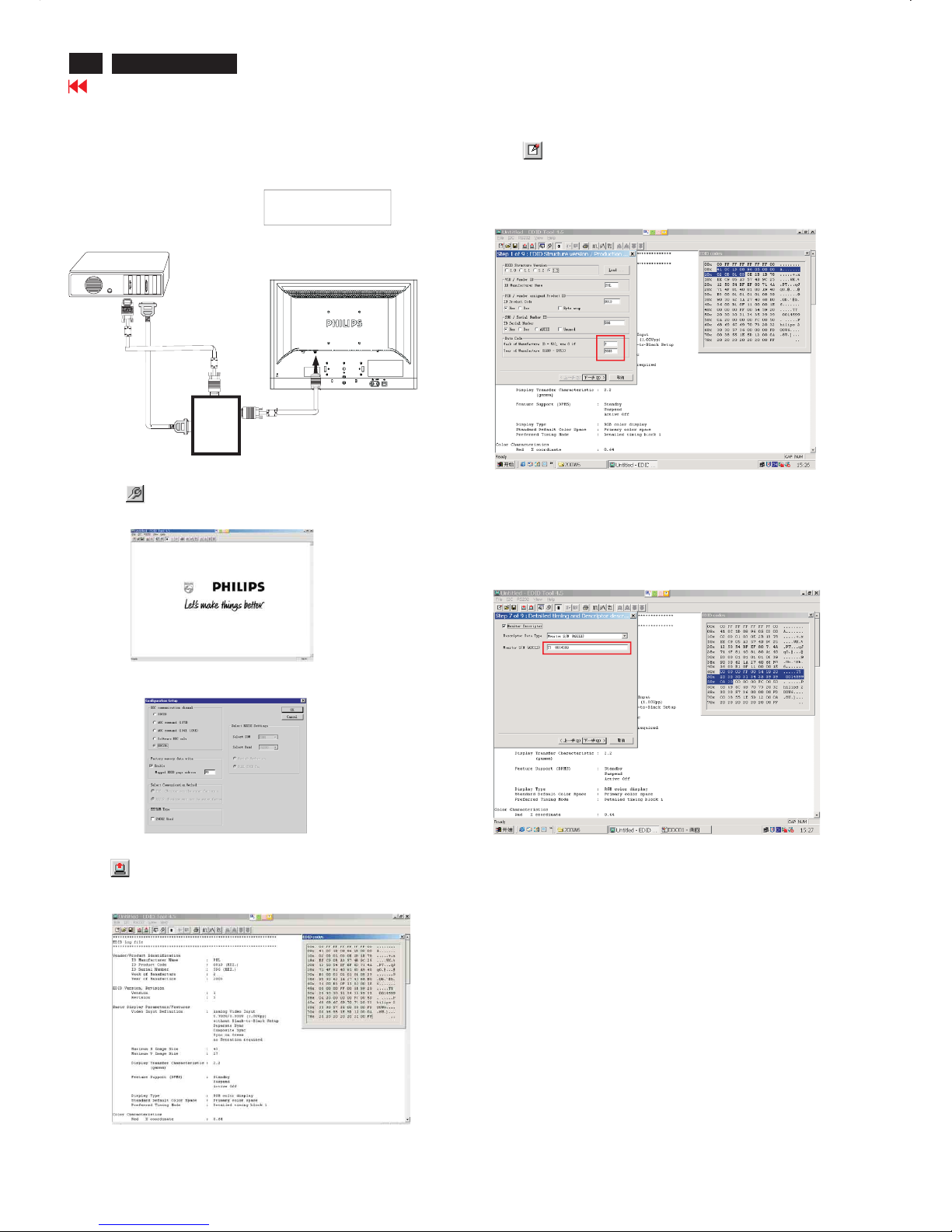
1. Click iconasshowninFig.11 from the tool bar to bring up
the Channels "Configuration Setup" windows as shown in Fig. 12.
Step 3: Modify DDC data (verify EDID version, week, year)
1. Click (new function) icon from the tool bar, bring up
Step 1 of 9 as shown in Fig. 15.
EDID45 DDC application provides the function selection and
text change (select & fill out) from Step 1 to Step 9.
Step 4: Modify DDC data (Monitor Serial No.)
Next
1. Click to step7, bring up Fig. 16.
- Serial number can be filled up or be changed at this moment.
- Click next,Finish to exit the Step window.
3. Click OK button to confirm your selection.
4. Click icon (Read EDID function) to read DDC EDID data from
monitor. The EDID codes will display on screen as shown in Fig. 14.
Fig. 16
2. Select the DDC2Bi as the communication channel.
As shown in Fig. 13.
Fig. 11
1=Power connector
2=D-SUB connector
Fig. 13
Fig. 14
Fig. 15
Don't close this screen. --->
Select and fill out,
If necessary.
Go to cover page
29
190P6&170P6 LCD
DDC Instructions
To Monitor
D-sub/DVI cable
DC 8~12V
To Printer port
Re-programming Digital DDC IC
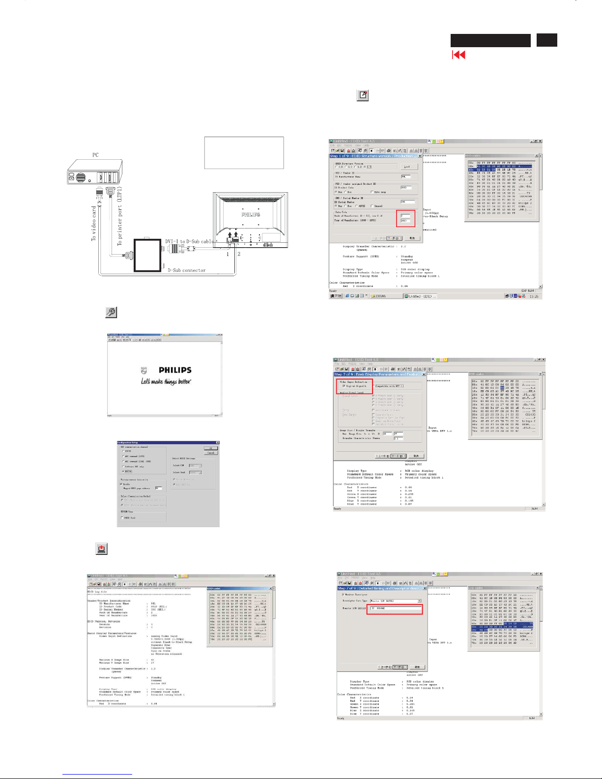
Step 1: After initialize alignment box, connecting all cables and
box as shown in Fig. 17
Fig. 18
Step 2: Read DDC data from monitor
1. Click icon as shown in Fig. 18 from the tool bar to bring up
the Channels "Configuration Setup" windows as shown in Fig. 19.
Step 3: Modify DDC data (verify EDID version, week, year)
1. Click (new function) icon from the tool bar, bring up
Step1of9asshowninFig.21.
EDID45 DDC application provides the function selection and
text change (select & fill out) from Step 1 to Step 9.
Step 4: Modify DDC data (Monitor Serial No.)
Next
1. Click , bring up Fig. 22. Then select Digital Signal as below
3. Click OK button to confirm your selection.
4. Click icon (Read EDID function) to read DDC EDID data from
monitor. The EDID codes will display on screen as shown in Fig. 20.
Fig. 22
Fig. 23
2. Select the DDC2Bi as the communication channel.
As shown in Fig. 19.
Fig. 19
Fig. 20
Fig. 21
Fig.17
Printer
Port
To Monitor
To PC
1=DVI connector
2=D-SUB connector
3=Power Plug
3
Don't close this screen. --->
To Monitor
D-sub/DVI cable
DC 8~12V
Select and fill out,
If necessary.
2. Click to step7, bring up Fig. 23.Next
- Serial number can be filled up or be changed at this moment.
- Click Next, Finish to exit the Step window.
Go to cover page
30
190P6&170P6 LCD
DDC Instructions
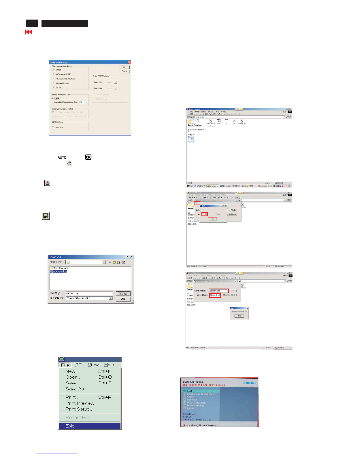
Step 6: Save DDC data
Sometimes, you may need to save DDC data as a text file for using
in other IC chip. To save DDC data, follow the steps below:
1. Click (Save) icon (or click "file"-> "save as") from the tool bar
And give a file name as shown in Fig. 25.
The file type is EDID46 file (*.ddc) which can be open in WordPad.
By using WordPad, the texts of DDC data & table (128 bytes, hex
code) can be modified. If DDC TEXTS & HEX Table are completely
correct, it can be saved as .ddc flie to re-load it into DDC IC for DDC
Data application.
2. Click .Save
Step 7: Exit DDC program
Pull down the File menu and select Exit as shown in Fig. 26.
Step 5: Write DDC data
1. Configuration should be as Fig. 24. And press OK.
3. Click (Write EDID) icon from the tool bar to write DDC data.
Fig. 24
Fig. 26
Fig. 25
2. Access Factory Mode
[Push AUTO " " & OK " " buttons at the same time and hold
it]+[Press power " " button untill comes out "Windows screen"]
=> then release all button
- Turn off monitor.
-
Step9:
-1. Disconnect the monitor power cord and connect it again.
-2. Press the OK button to bring up the OSD main manu.
-3. Re-confirm the serial Number is updated as shown in Fig.31.
Step :8 Modify serial number in OSD
-1. Unzip the serial number.zip to your computer, then open the folder
as shown in Fig.28.
-2.IfuseWin98 OS, you can execute SN.exe directly.
If use Win2000 or XP OS, first, you must execute install.bat, then
execute SN.exe
-3. Set I2C bus(press the left-top button of operating window) as shown
in Fig.28, then press " SET" button.
-4. Set Block4 as shown in Fig.30
-5. key in new serial number, then press " Write" button as shown in
Fig.30 , Click " WRITE" button.
-6. It will appear" Serial Number Write OK" , Click" Enter" to finish it.
Fig.28
Fig.29
Fig.30
Edid45.1
Fig.31
190P6
Go to cover page

31
190P6&170P6 LCD
DDC DATA(190P6)
THE DISPLA Y DATA CHANNEL (DDC_2B)CONTENT
INCLUDING (FOR 190P6 ANALOG)
**********************************************************************
EDID log file
**********************************************************************
Vendor/Product Identification
ID Manufacturer Name : PHL
IDProduct Code : 0831 (HEX.)
ID Serial Number : 1234 (HEX.)
Week of Manufacture : 20
Year of Manufacture : 2005
EDID Version, Revision
Version : 1
Revision : 3
Basic Display Parameters/Features
Video Input Definition : Analog Video Input
0.700V/0.300V (1.00Vpp)
Blank-to-Black Setup
Separate Sync
Composite Sync
Sync on Green
Serration required
Maximum H Image Size : 38
Maximum V Image Size : 30
Display Transfer Characteristic : 2.2
(gamma)
Feature Support (DPMS) : Standby
Suspend
Active Off
Display Type : RGB color display
Standard Default Color Space : Primary color space
Preferred Timing Mode : Detailed timing block 1
Color Characteristics
Red X coordinate : 0.636
Red Y coordinate : 0.348
Green X coordinate : 0.292
Green Y coordinate : 0.618
Blue X coordinate : 0.142
Blue Y coordinate : 0.072
White X coordinate : 0.313
White Y coordinate : 0.329
Established Timings
Established Timings I : 720 x400 @70Hz (
IBM,VGA)
640 x480 @60Hz (IBM,VGA)
640 x480 @67Hz (Apple,Mac II)
640 x480 @72Hz (VESA)
640 x480 @75Hz (VESA)
800 x 600 @56Hz (VESA)
800 x 600 @60Hz (VESA)
Established Timings II : 800 x 600 @72Hz (VESA)
800 x 600 @75Hz (VESA)
832x624 @75Hz (Apple,Mac II)
1024 x 76
8@60Hz (VESA)
1024 x 768@70Hz (VESA)
1024 x 768@75Hz (VESA)
1280 x 1024 @75Hz (VESA)
Manufacturer's timings : 1152 x 870 @75Hz (Apple,Mac II)
Standard Timing Identification #1
Horizontal active pixels : 1152
Aspect Ratio : 4:3
Refresh Rate : 70
Standard Timing Identification #2
Horizontal active pixels : 1152
Aspect Ratio : 4:3
Refresh Rate : 75
Standard Timing Identification #3
Horizontal active pixels : 1280
Aspect Ratio : 4:3
Refresh Rate : 60
Standard Timing Identification #4
Horizontal active pixels : 1280
Aspect Ratio : 5:4
Refresh Rate : 60
Detailed Timing #1
Pixel C
lock (MHz) : 135
H Active (pixels) : 1280
H Blanking (pixels) :408
V Active (lines) : 1024
V Blanking (lines) :42
H Sync Offset (F Porch)(pixels):48
HSyncPulse Width (pixels) : 112
V Sync Offset (F Porch)(lines) : 1
VSyncPulse Width (lines) : 3
H Image Size (mm) : 376
VImageSize(mm) : 301
HBorder(pixels) : 0
VBorder(lines) : 0
Flags : Non-interlaced
:NormalD
isplay, No stereo
: Digital Separate sync.
: Positive Vertical Sync.
: Positive Horizontal Sync.
Monitor Descriptor #2
Serial Number : TY 123456
Monitor Descriptor #3
Monitor Name : Philips 190P
Monitor Descriptor #4
Monitor Range Limits
Min. Vt rate Hz : 56
Max. Vt rate Hz : 76
Min. Horiz. rate kHz : 30
Max. Horiz. rate kHz : 83
Max. Supported Pixel : 140
No secondary GTF timing formula supported.
Extension Flag : 0
Check sum : 00 (HEX.)
**********************************************************************
EDID data (128 bytes)
**********************************************************************
0: 00 1:ff 2:ff 3:ff 4:ff 5:ff 6:ff 7: 00
8: 419: 0c 10: 31 11: 08 12: 34 13: 12 14:
00 15: 00
16: 14 17: 0f 18: 01 19: 03 20: 1f21:26 22: 1e23: 78
24: ee 25: cd 26: 6527:a2 28:59 29:4a 30: 9e 31:24
32: 12 33:5034: 54 35: bf 36:ef 37:8038: 71 39:4a
40: 71 41:4f 42:81 43:40 44: 81 45: 80 46: 01 47: 01
48: 01 49: 01 50: 01 5
1: 01 52: 01 53: 01 54: bc 55: 34
56: 00 57: 9858:51 59: 00 60:2a 61:4062: 30 63: 70
64: 13 65: 00 66: 78 67:2d 68: 11 69: 00 70: 00 71: 1e
72: 00 73: 00 74: 00 75: ff 76: 00 77:2078: 54 79:59
80:20 81:20 82: 31 83: 32 84: 33 85: 3486: 3587: 36
88: 0a89
:2090: 00 91: 00 92: 00 93:fc 94: 00 95: 50
96: 68 97: 69 98: 6c 99: 69 100: 70 101: 73 102: 20103: 31
104: 39 105: 30 106:50107: 0a 108: 00 109: 00 110: 00 111:fd
112: 00 113: 38 114: 4c 115: 1e 116:53117: 0e 118: 00 119: 0a
120:20121:20122: 20123:20124: 20125: 20126: 00 12
7: 00
Go to cover page

32
190P6&170P6 LCD
DDC DATA(190P6)
THE DISPLAYDATA CHANNEL (DDC-2B) CONTENT INCL UDING
(FOR 190P6 DIGITAL)
**********************************************************************
EDID log file
**********************************************************************
Vendor/Product Identification
ID Manufacturer Name : PHL
ID Product Code : 0831 (HEX.)
ID Serial Number : 1234 (HEX.)
Week of Manufacture : 20
Year of Manufacture : 2005
EDID Version, Revision
Version : 1
Revision : 3
Basic Display Parameters/Features
Video Input Definition : Digital Video Input
Maximum H Image Size : 38
Maximum V Image Size : 30
Display Transfer Characteristic : 2.2
(gamma)
Feature Support (DPMS) : Standby
Suspend
Active Off
Display Type : RGB color display
Standard Default Color Space : Primary color space
Preferred Timing Mode : Detailed timing block 1
Color Characteristics
Red X coordinate : 0.636
Red Y coordinate : 0.348
Green X coordinate : 0.292
Green Y coordinate : 0.618
Blue X coordinate : 0.142
Blue Y coordinate : 0.072
White X coordinate : 0.313
White Y coordinate : 0.329
Established Timings
Established Timings I : 720 x 400 @70Hz (IBM,VGA)
640 x 480 @60Hz (IBM,VGA)
640 x 480 @67Hz (Apple,Mac II)
640 x 480 @72Hz (VESA)
640 x 480 @75Hz (VESA)
800 x 600 @56Hz (VESA)
800 x 600 @60Hz (VESA)
Established Timings II : 800 x 600 @72Hz (VESA)
800 x 600 @75Hz (VESA)
832 x 624 @75Hz (Apple,Mac II)
1024 x 768 @60Hz (VESA)
1024 x 768 @70Hz (VESA)
1024 x 768 @75Hz (VESA)
1280 x 1024 @75Hz (VESA)
Manufacturer's timings : 1152 x 870 @75Hz (Apple,Mac II)
Standard Timing Identification #1
Horizontal active pixels : 1152
Aspect Ratio : 4:3
Refresh Rate : 70
Standard Timing Identification #2
Horizontal active pixels : 1152
Aspect Ratio : 4:3
Refresh Rate : 75
Standard Timing Identification #3
Horizontal active pixels : 1280
Aspect Ratio : 4:3
Refresh Rate : 60
Standard Timing Identification #4
Horizontal active pixels : 1280
Aspect Ratio : 5:4
Refresh Rate : 60
Detailed Timing #1
Pixel Clock (MHz) : 135
H Active (pixels) : 1280
H Blanking (pixels) : 408
V Active (lines) : 1024
V Blanking (lines) :42
H Sync Offset (FPorch)(pixels):48
H Sync Pulse Width (pixels) : 112
V Sync Offset (FPorch)(lines) :1
V Sync Pulse Width (
lines) :3
H Image Size (mm) : 376
V Image Size (mm) : 301
H Border (pixels) :0
V Border (lines) :0
Flags : Non-interlaced
: Normal Display, No stereo
: Digital Separate sync.
: Positive Vertical Sync.
: Positive Horizontal Sync.
Monitor Descriptor #2
Serial Number : TY 123456
Monitor Descriptor #3
Monitor Name : Philips 190P
Monitor Descriptor #4
Monitor Range Limits
Min. Vt rate Hz : 56
Max. Vt rate Hz : 76
Min. Horiz. rate kHz : 30
Max. Horiz. rate kHz : 83
Max. Supported Pixel : 140
No secondary GTF timing formula supported.
Extension Flag : 0
Check sum : 9F (HEX.)
**********************************************************************
EDID data (128 bytes)
**********************************************************************
0: 00 1: ff 2: ff 3: ff 4: ff 5: ff 6: ff 7: 00
8: 41 9: 0c 10: 31 11: 08 12: 34 13: 12 14: 00 15: 00
16: 14 17: 0f 18: 01 19: 03 20: 80 21: 26 22: 1e 23: 78
24: ee 25: cd 26: 65 27: a2 28: 59 29: 4a 30: 9e 31: 24
32: 12 33: 50 34: 54 35: bf 36: ef 37: 80 38: 71 39: 4a
40: 71 41: 4f 42: 81 43: 40 44: 81 45: 80 46: 01 47: 01
48: 01 49: 01 50: 01 51: 01 52: 01 53: 01 54: bc 55: 34
56: 00 57: 98 58: 51 59: 00 60: 2a 61: 40 62: 30 63: 70
64: 13 65: 00 66: 78 67: 2d 68: 11 69: 00 70: 00 71: 1e
72: 00 73: 00 74: 00 75: ff 76: 00 77: 20 78: 54 79: 59
80: 20 81: 20 82: 31 83: 32 84: 33 85: 34 86: 35 87: 36
88: 0a 89: 20 90: 00 91: 00 92: 00 93: fc 94: 00 95: 50
96: 68 97: 69 98: 6c 99: 69 100: 70 101: 73 102: 20 103: 31
104: 39 105: 30 106: 50 107: 0a 108: 00 109: 00 110: 00 111: fd
112: 00 113: 38 114: 4c 115: 1e 116: 53 117: 0e 118: 00 119: 0a
120: 20 121: 20 122: 20 123: 20 124: 20 125: 20 126: 00 127: 9f
Go to cover page

33
190P6&170P6 LCD
DDC DATA(170P6)
THE DISPLAY DATA CHANNEL (DDC_2B)CONTENT INCLUDING
(FOR 170P6 ANALOG)
**********************************************************************
EDID log file
**********************************************************************
Vendor/Product Identification
ID Manufacturer Name : PHL
IDProduct Code : 082E (HEX.)
ID Serial Number : 1234 (HEX.)
Week of Manufacture : 16
Year of Manufacture : 2005
EDID Version, Revision
Version : 1
Revision : 3
Basic Display Parameters/Features
Video Input Definition : Analog Video Input
0.700V/0.300V (1.00Vpp)
Blank-to-Black Setup
Separate Sync
Composite Sync
Sync on Green
Serration required
Maximum H Image Size : 34
Maximum V Image Size : 27
Display Transfer Characteristic : 2.2
(gamma)
Feature Support (DPMS) : Standby
Suspend
Active Off
Display Type : RGB color display
Standard Default Color Space : Primary color space
Preferred Timing Mode : Detailed timing block 1
Color Characteristics
Red X coordinate : 0.641
Red Y coordinate : 0.342
Green X coordinate : 0.292
Green Y coordinate : 0.611
Blue X coordinate : 0.147
Blue Y coordinate : 0.068
White X coordinate : 0.313
White Y coordinate : 0.329
Established Timings
Established Timings I : 720 x400 @70
Hz (IBM,VGA)
640 x480 @60Hz (IBM,VGA)
640 x480 @67Hz (Apple,Mac II)
640 x480 @72Hz (VESA)
640 x480 @75Hz (VESA)
800 x 600 @56Hz (VESA)
800 x 600 @60Hz (VESA)
Established Timings II : 800 x 600 @72Hz (VESA)
800 x 600 @75Hz (VESA)
832x624 @75Hz (Apple,Mac II)
10
24 x 768@60Hz (VESA)
1024 x 768@70Hz (VESA)
1024 x 768@75Hz (VESA)
1280 x 1024 @75Hz (VESA)
Manufacturer's timings : 1152 x 870 @75Hz (Apple,Mac II)
Standard Timing Identification #1
Horizontal active pixels : 1152
Aspect Ratio : 4:3
Refresh Rate : 70
Standard Timing Identification #2
Horizontal active pixels : 1152
Aspect Ratio : 4:3
Refresh Rate : 75
Standard Timing Identification #3
Horizontal active pixels : 1280
Aspect Ratio : 4:3
Refresh Rate : 60
Standard Timing Identification #4
Horizontal active pixels : 1280
Aspect Ratio : 5:4
Refresh Rate : 60
Detailed Timing #1
Pixel Clock (MHz) : 108
H Active (pixels) : 1280
H Blanking (pixels) :408
V Active (lines) : 1024
V Blanking (lines) :42
H Sync Offset (F Porch)(pixels):48
HSyncPulse Width (pixels) : 112
V Sync Offset (F Porch)(lines) : 1
VSyncPulse Width (lines) : 3
H Image Size (mm
) : 338
V Image Size (mm) :270
H Border (pixels) : 0
V Border (lines) : 0
Flags : Non-interlaced
:NormalDisplay, No stereo
: Digital Separate sync.
: Positive Vertical Sync.
: Positive Horizontal Sync.
Monitor Descriptor #2
Serial Number : TY 123456
Monitor Descriptor #3
Monitor Name : Philips 170P
Monitor Descriptor #4
Monitor Range Limits
Min. Vt rate Hz : 56
Max. Vt rate Hz : 76
Min. Horiz. rate kHz : 30
Max. Horiz. rate kHz : 83
Max. Supported Pixel : 140
No secondary GTF timing formula supported.
Extension Flag : 0
Check sum : 0C (HEX.)
**********************************************************************
EDID data (128 bytes)
**********************************************************************
0: 00 1:ff 2:ff 3:ff4:ff5:ff6
:ff 7: 00
8: 419: 0c 10:2e 11: 08 12: 34 13: 12 14: 00 15: 00
16: 10 17: 0f 18: 01 19: 03 20: 1f21:22 22:1b23: 78
24: ee 25: 2e 26:e5 27: a4 28: 57 29:4a 30: 9c 31:25
32: 11 33:5034: 54 35: bf 36:ef 37:8038: 71 39:4a
40: 71 41: 4f 42: 81 43:40 44: 81 45: 80 46
: 01 47: 01
48: 01 49: 01 50: 01 51: 01 52: 01 53: 01 54: 30 55: 2a
56: 00 57: 9858:51 59: 00 60:2a 61:4062: 30 63: 70
64: 13 65: 00 66:52 67: 0e 68: 11 69: 00 70: 00 71: 1e
72: 00 73: 00 74: 00 75: ff 76: 00 77:2078: 54 79:59
80:20 81:20 82: 31 83:
32 84: 33 85: 3486: 3587: 36
88: 0a89:2090: 00 91: 00 92: 00 93:fc 94: 00 95: 50
96: 68 97: 69 98: 6c 99: 69 100: 70 101: 73 102: 20 103: 31
104: 37 105: 30 106:50 107: 0a 108: 00 109: 00 110: 00 111:fd
112: 00 113: 38 114: 4c 115: 1e 116:53 117: 0e 118: 00 119: 0a
120:20121
:20122: 20123:20124: 20125: 20126: 00 127: 0c
Go to cover page

34
190P6&170P6 LCD
DDC DATA(170P6)
THE DISPLAYDATA CHANNEL (DDC-2B) CONTENT INCL UDING
(FOR 170P6 DIGITAL)
**********************************************************************
EDID log file
**********************************************************************
Vendor/Product Identification
ID Manufacturer Name : PHL
ID Product Code : 082E (HEX.)
ID Serial Number : 1234 (HEX.)
Week of Manufacture : 16
Year of Manufacture : 2005
EDID Version, Revision
Version : 1
Revision : 3
Basic Display Parameters/Features
Video Input Definition : Digital Video Input
Maximum H Image Size : 34
Maximum V Image Size : 27
Display Transfer Characteristic : 2.2
(gamma)
Feature Support (DPMS) : Standby
Suspend
Active Off
Display Type : RGB color display
Standard Default Color Space : Primary color space
Preferred Timing Mode : Detailed timing block 1
Color Characteristics
Red X coordinate : 0.641
Red Y coordinate : 0.342
Green X coordinate : 0.292
Green Y coordinate : 0.611
Blue X coordinate : 0.147
Blue Y coordinate : 0.068
White X coordinate : 0.313
White Y coordinate : 0.329
Established Timings
Established Timings I : 720 x 400 @70Hz (IBM,VGA)
640 x 480 @60Hz (IBM,VGA)
640 x 480 @67Hz (Apple,Mac II)
640 x 480 @72Hz (VESA)
640 x 480 @75Hz (VESA)
800 x 600 @56Hz (VESA)
800 x 600 @60Hz (VESA)
Established Timings II : 800 x 600 @72Hz (VESA)
800 x 600 @75Hz (VESA)
832 x 624 @75Hz (Apple,Mac II
)
1024 x 768 @60Hz (VESA)
1024 x 768 @70Hz (VESA)
1024 x 768 @75Hz (VESA)
1280 x 1024 @75Hz (VESA)
Manufacturer's timings : 1152 x 870 @75Hz (Apple,Mac II)
Standard Timing Identification #1
Horizontal active pixels : 1152
Aspect Ratio : 4:3
Refresh Rate : 70
Standard Timing Identification #2
Horizontal active pixels : 1152
Aspect Ratio : 4:3
Refresh Rate : 75
Standard Timing Identification #3
Horizontal active pixels : 1280
Aspect Ratio : 4:3
Refresh Rate : 60
Standard Timing Identification #4
Horizontal active pixels : 1280
Aspect Ratio : 5:4
Refresh Rate : 60
Detailed Timing #1
Pixel Clock (MHz) : 108
H Active (pixels) : 1280
H Blanking (pixels) : 408
V Active (lines) : 1024
V Blanking (lines) :42
H Sync Offset (FPorch)(pixels):48
H Sync Pulse Width (pixels) : 112
V Sync Offset (FPorch)(lines) :1
V Sync Pulse Width (lines)
:3
H Image Size (mm) : 338
V Image Size (mm) : 270
H Border (pixels) :0
V Border (lines) :0
Flags : Non-interlaced
: Normal Display, No stereo
: Digital Separate sync.
: Positive Vertical Sync.
: Positive Horizontal Sync.
Monitor Descriptor #2
Serial Number : TY 123456
Monitor Descriptor #3
Monitor Name : Philips 170P
Monitor Descriptor #4
Monitor Range Limits
Min. Vt rate Hz : 56
Max. Vt rate Hz : 76
Min. Horiz. rate kHz : 30
Max. Horiz. rate kHz : 83
Max. Supported Pixel : 140
No secondary GTF timing formula supported.
Extension Flag : 0
Check sum : AB (HEX.)
**********************************************************************
EDID data (128 bytes)
**********************************************************************
0: 00 1: ff 2: ff 3: ff 4: ff 5: ff 6: ff 7: 00
8: 41 9: 0c 10: 2e 11: 08 12: 34 13: 12 14: 00 15: 00
16: 10 17: 0f 18: 01 19: 03 20: 80 21: 22 22: 1b 23: 78
24: ee 25: 2e 26: e5 27: a4 28: 57 29: 4a 30: 9c 31: 25
32: 11 33: 50 34: 54 35: bf 36: ef 37: 80 38: 71 39: 4a
40: 71 41: 4f 42: 81 43: 40 44: 81 45: 80 46: 01 47: 01
48: 01 49: 01 50: 01 51: 01 52: 01 53: 01 54: 30 55: 2a
56: 00 57: 98 58: 51 59: 00 60: 2a 61: 40 62: 30 63: 70
64: 13 65: 00 66: 52 67: 0e 68: 11 69: 00 70: 00 71: 1e
72: 00 73: 00 74: 00 75: ff 76: 00 77: 20 78: 54 79: 59
80: 20 81: 20 82: 31 83: 32 84: 33 85: 34 86: 35 87: 36
88: 0a 89: 20 90: 00 91: 00 92: 00 93: fc 94: 00 95: 50
96: 68 97: 69 98: 6c 99: 69 100: 70 101: 73 102: 20 103: 31
104: 37 105: 30 106: 50 107: 0a 108: 00 109: 00 110: 00 111: fd
112: 00 113: 38 114: 4c 115: 1e 116: 53 117: 0e 118: 00 119: 0a
120: 20 121: 20 122: 20 123: 20 124: 20 125: 20 126: 00 127: ab
Go to cover page

35
190P6&170P6 LCD
Go to cover page
ISP CABLE FOR CPU
Configuration and procedure
ISP ( In System Program) software is provided by Genesis to upgrade
the firmware of CPU.
ISP cable is for the interface between "Parallel port of PC" and
"15 pin-D-SUB connector of monitor.
System and equipment requirements:
1. An i386 (or above ) personal computer or compatible.
2. Microsoft operation system Win 95/98 or Win 2000
3. ISP software
4. ISP cable (3138 106 10148) as shown in Fig.1
Fig.1 ISP CABLE :12NC IS "3138 106 10148".
5.Connect ISP cable and main cord to monitor as shown in Fig.2.
6. Install and setup the Gprobe 4.5.0.5.exe program
step 1. Create a folder in your PC .for example: D:\190P6
step 2.Copy ISP software 190P6 software .Zip into your folder
step 3.Unzip ISP.ZIP into your folder as shpwn in Fig.3
step 4.Double click the Gprobe4.5.0.5.exe icon to install the
application as shown Fig.4
Fig.3
Fig.4
Step 5 . Click the next till the setup finished. And creat a short cut on the desktop.

Go to cover page
36
190P6&170P6 LCD
ISP CABLE for CPU
Update the firmware
1. Double click the Gprobe.exe icon ,then appears window
as shown in Fig.5
2. Press the options then choose configure Pin as shown in Fig.5
3. From the menu that appears, choose the number 17 in "output
pin and the number 12 in " input pin as shown in Fig.6
Fig.5
Fig.6
4. Press the options then choose connection setup as shown in
Fig.7
5. From the menu that appears , choose the DDC2Bi3 in "protocol"
and the LPT (0x378) in "port" as shown in Fig.8
Fig.7
Update the firmware
click the commands and select the Batch, as
shown in Fig.9, Fig.10
Fig.8
Fig.9
Fig.10
Click the button as shown in Fig.10 to browse the Iicisp.txt file in the
folder that you create.
Note: you should pay attention to the path in the Iicisp.txt file.
It is the same as the folder's path that you create.

37
190P6&170P6 LCD
Go to cover page
ISP CABLE FOR CPU
Fig.11 click "OPEN"
Shut of the AC power
Click the "OK" button and then connect the AC power, after the follow
window appears, the update is completed.
The isp instructions between 170P6 and 190P6 is the same except the hex code

Go to cover page
38
190P6&170P6 LCD
Wiring Diagram(190P6)

39
190P6&170P6 LCD
Go to cover page
Wiring Diagram(170P6)

Block Diagram
40
190P6&170P6 LCD

Scaler Diagram(190P6)
41
190P6&170P6 LCD

Scaler Diagram(190P6)
42
190P6&170P6 LCD

Scaler Diagram(190P6)
43
190P6&170P6 LCD

Scaler Diagram(190P6)
44
190P6&170P6 LCD

Scaler Diagram(190P6)
45
190P6&170P6 LCD

Scaler Board C.B.A
46
190P6&170P6 LCD

Scaler Board C.B.A
47
190P6&170P6 LCD

Scaler Diagram(170P6)
48
190P6&170P6 LCD

Scaler Diagram(170P6)
49
190P6&170P6 LCD

Scaler Diagram(170P6)
50
190P6&170P6 LCD

Scaler Diagram(170P6)
51
190P6&170P6 LCD

Scaler Diagram(170P6)
52
190P6&170P6 LCD

USB Diagram(190P6)
53
190P6&170P6 LCD

USB Diagram(190P6)
54
190P6&170P6 LCD

USB Board C.B.A
55
190P6&170P6 LCD

USB Board C.B.A
56
190P6&170P6 LCD

USB Diagram(170P6)
57
190P6&170P6 LCD

USB Diagram(170P6)
58
190P6&170P6 LCD

Audio Diagram(190P6)
59
190P6&170P6 LCD

Audio Board C.B.A
60
190P6&170P6 LCD

Control Diagram&C.B.A(190P6)
61
190P6&170P6 LCD

Control&Audio Diagram (170P6)
62
190P6&170P6 LCD

Control&Audio Diagram&C.B.A(170P6)
63
190P6&170P6 LCD

Power Diagram
64
190P6&170P6 LCD

Power Diagram
65
190P6&170P6LCD

Power Board C.B.A
66
190P6&170P6 LCD

67
190P6&170P6 LCD
Go to cover page
Exploded View(190P6ES/00)
8164
823827717981
SENSOR ASSEMBLY
32
313815415931
STRIP-DECORATION(T)
31
313815415991
BEZEL(S)
33
313815416061
BUTTON-CONTROL(S)
34
31381541
1231
LENS-POWER
1050
823827717621
TFT-LCD M
190EN0
4 V
.5(AUO0)
35
313815415941
LIGHT FRAME KEY
1160
313815863901
METAL FRAME+WIRE ASSY-AU
1051
313815863881
SCALER ASSY-AU
1052
823827717121
LIPS(AIP-0093A)
313815410901
INSULATE PLATE
45
46
31381540501
1
RUBBER-SLEEVE
31381513351
1
VESA PLATE
43
313815137201
KENSIN
GT
ON PLATE
44
313815863871
USB ASSY
313815863791
AUDIO ASSY
1054
1055
313815861681
CONTROL ASSY
1053
31381541601
1
BACK COVER(S)
41
31381541
1951
PLATE-VENT
42
313815416021
BACK COVER(S)-LPL
823827717801
TFT-LCD LM
190E04-A4
313815863821
SCALER ASSY
1051
313815863861
METAL FRAME+WIRE ASSY

68
190P6&170P6 LCD
Exploded View(170P6ES/00)
To Printer port
313815759421
BEZELASSY(S)
30
823827716861
LCD LM170
E01-A6
1056
313815863851
METAL FRAME+WIRE ASSY
1160
313815759451
BACK CO
VERASSY(S)
40
313815412801
HINGE DECO CO
VER(S)
101

69
190P6&170P6 LCD
Go to cover page
Recommended parts list
0040 313815759281 BACK COVER ASSY(S)-AU
0041 313815416011 BACK COVER(S)
0042 313815411951 PLATE-VENT
0043 313815133511 VESA PLATE
0044 313815137201 KENSINGTON PLATE
0045 313815410901 INSULATE PLATE
0046 313815405011 RUBBER-SLEEVE
0030 313815759271 FRONT BEZEL ASSY(S)
0602 313811708291 E-DFU
1161 313819871471 CORD DVI 18+1/1M8/DVI 18+1 BK
1162 313818878161 AUDIO CABLE
1163 313819875351 LSP BOX 16R 2W PS-010023
7621 932222269668 IC SM TPS2062DG4(TI00)R
7625 932222269668 IC SM TPS2062DG4(TI00)R
7722 932217440685 TRA SIG SM KRC102S (KEC0) R
7725 932216638668 FET POW SM SI5441DC-E3 (VISH)R
7731 823827717521 IC
7751 932222162671 IC SM CY7C65640-LFXC (CYPR) Y
7203 932216972682 IC SM AT24C02N-10SC-2.7(ATME)L
7204 932216972682 IC SM AT24C02N-10SC-2.7(ATME)L
7211 935260739118 IC SM 74LVC14APW (PHSE) R
7301 313815863831 CPU IC ASSY
7301 932219106682 IC SM AT49LV002NT-90JU (ATME)L
7302 313815863891 EEPROM ASSY-AU
7302 932218650682 IC AT24C16A-10PU-2.7 (ATME) L
7403 932220099685 IC SM LD1117AS18 (ST00) R
7404 932220818671 IC SM GM5321-BC (GEMI) Y
7405 932222076668 IC SM AME1117CCGTZ (AME0) R
7501 932217439685 TRA SIG SM BC857C (KEC0) R
7502 932217439685 TRA SIG SM BC857C (KEC0) R
7503 932217440685 TRA SIG SM KRC102S (KEC0) R
7504 932216638668 FET POW SM SI5441DC-E3 (VISH)R
7505 932217439685 TRA SIG SM BC857C (KEC0) R
7506 932217440685 TRA SIG SM KRC102S (KEC0) R
7507 932217440685 TRA SIG SM KRC102S (KEC0) R
7508 932216638668 FET POW SM SI5441DC-E3 (VISH)R
7509 932217439685 TRA SIG SM BC857C (KEC0) R
7601 932219359668 IC SM AME8815AEGT150Z (AME0) R
7602 932218246668 IC SM AME8815AEGT250Z (AME0) R
7603 823827716651 LIGHT FRAME IC

190P6&170P6 LCD
Go to cover page
70
Model:190P6ES/00(AUO PANEL)
Mechanical Parts
0040 313815759281 BACK COVER ASSY(S)-AU
0041 313815416011 BACK COVER(S)
0042 313815411951PLATE-VENT
0043 313815133511 VESA PLATE
0044 313815137201 KENSINGTON PLATE
0045 313815410901 INSULATE PLATE
0046 31381540
5011 RUBBER-SLEEVE
0030 313815759271 FRONT BEZEL ASSY(S)
0031 313815415991 BEZEL(S)
0032 313815415931 STRIP-DECORATION(T)
0033 313815416061 BUTTON-CONTROL(S)
0034 313815411231LENS-POWER
0035 313815415941LIGHT FRAM E KEY
8164 823827717981 SENSOR ASSEMBLY
0050
313815759231 SUPER ERGO BASE(B)
0094313815414241LOGO COVER (S)
0107 313810440571 HOUSING COVER
1157 242207000075MAINSCORD IEC10A 1M5 DET 3P B
1158 313819875131CORD SUB- D15/1M5/SUB-D15BK
1159 313819872531CORD USB A/1M8/USBBBK
1160 313815863901 META
L FRAM E+WIRE ASSY-AU
LCD P anel
1050 823827717621 TFT-LCD M190EN04V.5(AUO0)
packing
0450 313815640061 CARTON
0451 313815640071 CUSHION-R
0452 313815640081CUSHION-L
0453 313810656651PE BAG
PCB ASSY
1051 313815863881 SCALER ASSY-AU
1052 823827717121LIPS(AIP-0093A)
1053 3138
15861681CONTROL ASSY
1054 313815863871 USB ASSY
1055 313815863791 AUDIO ASSY
ACCESSORY
0602313811708291 E-DFU
1161 313819871471 CORDDVI 18+1/1M8/DVI 18+1 BK
1162313818878161 AUDIO CABLE
1163313819875351LSP BOX 16R2WPS-010023
Miscellanea
0291 313815567001 LABEL-CPU
0295313815567021LABEL-EEPROM-AU
0615313811708361 HEX CODEOFF/W(NOMATL REQ)
1201 242203300521 SOCDVI H 24P F 1.91DVI-D Y
1203 242202518065SOC SUBD H 15P FBU900 Y
1302 243803100435 SOC IC V8P F2.54DI
LL
1410 243854300086 RES XTL SM 14M318 18P HC49/S R
1502 242202518824 CON V 11P M2.00 63391 B
1503 242202518089CON V 12P M2.00 63392B
1507 242202518822 CON V 9P M2.00 63389 B
1603 242202505572 CONH30P M 1.25 SM 60952 R
4444 313810610459CDROM - SERVICE MANUAL
4444 313810610460 CD ROM - SERVICE MANUAL
8161 313819875421CBLE330019 9/290/9-019 AWG28
8162313819875411 CBLE330022 12/295+220/7+4
8163313819871401 CBLE-030 30/135/30-012 AWG28
8938 313819874941CBLE FAST 5.8/100/FAST AWG18
893
9 313819871551CBLE FAST/70/FAST AWG18
PCB ASSY
1051 313815863881 SCALER ASSY-AU
2209 223878615649CER2 0603X7R 16V 100N PM10 R
2211 223886715331CER1 0603NP0 50V330P PM5 R
2212 223886715331CER1 0603NP0 50V330P PM5 R
2214 223878615649CER2 0603X7
R 16V 100N PM10 R
2216 223886715331CER1 0603NP0 50V330P PM5 R
2217 223886715331CER1 0603NP0 50V330P PM5 R
2218 223886715339CER1 0603NP0 50V33PPM5 R
2219 223886715221CER1 0603NP0 50V220P PM5 R
2220 223878615649CER2 0603X7R 16V 100N PM10 R
2221 22387861564
9CER2 0603X7R 16V 100N PM10 R
2225 223858615636CER2 0603X7R50V 10N PM10 R
2227 223858615636CER2 0603X7R50V 10N PM10 R
2229 223858615636CER2 0603X7R50V 10N PM10 R
2231 223858615636CER2 0603X7R50V 10N PM10 R
2233 223878615
649CER2 0603X7R 16V 100N PM10 R
2234 223878615649CER2 0603X7R 16V 100N PM10 R
2235 223878615649CER2 0603X7R 16V 100N PM10 R
2301 223878615649CER2 0603X7R 16V 100N PM10 R
2302 223878615649CER2 0603X7R 16V 100N P
M10 R
2401 202002191778ELCAP SM RVJ 16V 100U PM20 R
2402202203100182 ELCAP SM RVS 25V 10U PM20 R
2403 223878615649CER2 0603X7R 16V 100N PM10 R
2404 223878615649CER2 0603X7R 16V 100N PM10 R
2405 223878615649CER2 060
3X7R 16V 100N PM10 R
2406 223878615649CER2 0603X7R 16V 100N PM10 R
2407 223878615649CER2 0603X7R 16V 100N PM10 R
2408202203100182 ELCAP SM RVS 25V 10U PM20 R
2409 223878615649CER2 0603X7R 16V 100N PM10 R
2410 223878615649CER2 0603X7R 16V 100N PM10 R
2411 223878615649CER2 0603X7R 16V 100N PM10 R
2412 223878615649CER2 0603X7R 16V 100N PM10 R
2413 223878615649CER2 0603X7R 16V 100N PM10 R
2414 223878615649CER2
0603X7R 16V 100N PM10 R
2415 223878615649CER2 0603X7R 16V 100N PM10 R
2416 223878615649CER2 0603X7R 16V 100N PM10 R
2417 223878615649CER2 0603X7R 16V 100N PM10 R
2418202202000789 ELCAP SM LV 16V 10
U PM20 R
2419 223878615649CER2 0603X7R 16V 100N PM10 R
2420 202202000789 ELCAP SM LV 16V 10U PM20 R
2421 223878615649CER2 0603X7R 16V 100N PM10 R
2422 202203100182 ELCAP SM RVS 25V 10U PM20 R
2423 223878615649C
ER2 0603X7R 16V 100N PM10 R
2424 223878615649CER2 0603X7R 16V 100N PM10 R
2425 223878615649CER2 0603X7R 16V 100N PM10 R
2426 223878615649CER2 0603X7R 16V 100N PM10 R
2427 223878615649CER2 0603X7R 16V 100N PM10 R
2428 202203100182 ELCAP SM RVS 25V 10U PM20 R
2429 202203100182 ELCAP SM RVS 25V 10U PM20 R
2430 202203100182 ELCAP SM RVS 25V 10U PM20 R
2431 223878615649CER2 0603X7R 16V 100N PM10 R
2432 223878615649CER2 0603X7R 16V 100N PM10 R
2433 223878615649CER2 0603X7R 16V 100N PM10 R
2434 223878615649CER2 0603X7R 16V 100N PM10 R
2435 202203100182 ELCAP SM RVS 25V 10U PM20 R
2436 223878615649CER2 0603X7R 16V 100N PM10 R
2437 202203100182 ELCAP SM RVS 25V 10U PM20 R
2438 223824619
863 CER2 0603Y5V10V 1U P8020 R
2439 202203100182 ELCAP SM RVS 25V 10U PM20 R
2440 223878615649CER2 0603X7R 16V 100N PM10 R
2441 223878615649CER2 0603X7R 16V 100N PM10 R
2442 223878615649CER2 0603X7R 16V 100N PM
10 R
2443 223878615649CER2 0603X7R 16V 100N PM10 R
2444 223878615649CER2 0603X7R 16V 100N PM10 R
2445 223878615649CER2 0603X7R 16V 100N PM10 R
2446 223878615649CER2 0603X7R 16V 100N PM10 R
2450 223886715478 CER1 0603NP0 5
0V4P7 PM 0P25 R
2451 223886715478 CER1 0603NP0 50V4P7 PM0P25 R
2453 223858615632 CER2 0603X7R50V4N7PM10 R
2454 223858615636CER2 0603X7R50V 10N PM10 R
2455 223858615636CER2 0603X7R50V 10N PM10 R
2456 223858615636CER2 0603X7R50V 10N PM10 R
2457 223886715109 CER1 0603NP0 50V 10P PM5 R
2461 222224119876 CER2 1206 Y5V 10V 10U P8020 R
2462 222224119876 CER2 1206 Y5V 10V 10U P8020 R
2501 223878615649CER2 0603X7R 16V 100N PM10 R
2502 223878615649CER2 0603X7R 16V 100N PM
10 R
2503202203100206 ELCAP SM HV 25V 47U PM20 R
2507 223878615649CER2 0603X7R 16V 100N PM10 R
2508 223878615649CER2 0603X7R 16V 100N PM10 R
2509 202203100206 ELCAP SM HV 25V 47U PM20 R
2510 223878615649CER2
0603X7R 16V 100N PM10 R
2511 223886715101 CER1 0603NP0 50V 100P PM5 R
2512 223878615649CER2 0603X7R 16V 100N PM10 R
2514 223878615649CER2 0603X7R 16V 100N PM10 R
2515 223878615649CER2 0603X7R 16V 100N PM10 R
2516 223878
615649CER2 0603X7R 16V 100N PM10 R
2517 223878615649CER2 0603X7R 16V 100N PM10 R
2518 223878615649CER2 0603X7R 16V 100N PM10 R
2519 223878615649CER2 0603X7R 16V 100N PM10 R
2520 223858615636CER2 0603X7R50
V 10N PM10 R
2521 202203100206 ELCAP SM HV 25V 47U PM20 R
2522 223878615649CER2 0603X7R 16V 100N PM10 R
2523 223878615649CER2 0603X7R 16V 100N PM10 R
2524 223858615636CER2 0603X7R50V 10N PM10 R
2525 223878615649CER2 0603X7
R 16V 100N PM10 R
2526 222224119876 CER2 1206 Y5V 10V 10U P8020 R
2527 223878615649CER2 0603X7R 16V 100N PM10 R
2530 222224119876 CER2 1206 Y5V 10V 10U P8020 R
2601 223878615649CER2 0603X7R 16V 100N PM10 R
2602 22387
8615649CER2 0603X7R 16V 100N PM10 R
2603 223878615649CER2 0603X7R 16V 100N PM10 R
2604 223878615649CER2 0603X7R 16V 100N PM10 R
2605 223878615649CER2 0603X7R 16V 100N PM10 R
2606 223878615649CER2 0603X
7R 16V 100N PM10 R
2607 223878615649CER2 0603X7R 16V 100N PM10 R
2608 223878615649CER2 0603X7R 16V 100N PM10 R
2609 202203100182 ELCAP SM RVS 25V 10U PM20 R
2610 223878615649CER2 0603X7R 16V 100N PM10 R
2611 2238
78615649CER2 0603X7R 16V 100N PM10 R
2612 223878615649CER2 0603X7R 16V 100N PM10 R
2613 223878615649CER2 0603X7R 16V 100N PM10 R
2614202203100182 ELCAP SM RVS 25V 10U PM20 R
2615202203100182 ELCAP SM RVS 25V 10U P
M20 R
2616 202203100182 ELCAP SM RVS 25V 10U PM20 R
2617 223878615649CER2 0603X7R 16V 100N PM10 R
2618202203100182 ELCAP SM RVS 25V 10U PM20 R
2619 223878615649CER2 0603X7R 16V 100N PM10 R
2620 223878615649CER2 060
3X7R 16V 100N PM10 R
2621 223878615649CER2 0603X7R 16V 100N PM10 R
2622 223878615649CER2 0603X7R 16V 100N PM10 R
2623 223878615649CER2 0603X7R 16V 100N PM10 R
2624 223878615649CER2 0603X7R 16V 100N
PM10 R
2625 223878615649CER2 0603X7R 16V 100N PM10 R
2626 223878615649CER2 0603X7R 16V 100N PM10 R
2627 223878615649CER2 0603X7R 16V 100N PM10 R
2628 223878615649CER2 0603X7R 16V 100N PM10 R
2
629 223878615649CER2 0603X7R 16V 100N PM10 R
2630 202203100182 ELCAP SM RVS 25V 10U PM20 R
2632 223878615649CER2 0603X7R 16V 100N PM10 R
2633 202203100182 ELCAP SM RVS 25V 10U PM20 R
2634 223878615649CER2 0603X7
R 16V 100N PM10 R
2636 223878615649CER2 0603X7R 16V 100N PM10 R
2637 222224119876 CER2 1206 Y5V 10V 10U P8020 R
2638 223878615649CER2 0603X7R 16V 100N PM10 R
3202212211805669 RST SM 0603RC0603 10K PM5 R
320
3212211805669 RST SM 0603RC0603 10K PM5 R
3204212211805669 RST SM 0603RC0603 10K PM5 R
3205 232270260223 RST SM 0603RC21 22K PM5 R
3206 232270260101 RST SM 0603RC21 100R PM5 R
3207 232270260101 RST SM 0603RC21 100R PM5 R
3208 232270260102 RST SM 0603RC211K PM5 R
3209 2322702
60104 RST SM 0603RC21 100K PM5 R
3210 232270260101 RST SM 0603RC21 100R PM5 R
3211 232270260101 RST SM 0603RC21 100R PM5 R
3213 232270260102 RST SM 0603RC211K PM5 R
3214 232270260472 RST SM 0603RC21 4K7PM5 R
3215212211805669 RST SM 0603RC0603 10K PM5 R
3216 232270260101 RST SM 0603RC
21 100R PM5 R
3217 232270260101 RST SM 0603RC21 100R PM5 R
3219 212211805669 RST SM 0603RC0603 10K PM5 R
3220 232270260223 RST SM 0603RC21 22K PM5 R
3221 212211805669 RST SM 0603RC0603 10K PM5 R
3222 212211805669 RST SM 0603RC0603 10K PM5 R
3223 232270260101 RST SM 0603RC21 100R
PM5 R
3224 232270260101 RST SM 0603RC21 100R PM5 R
3225 232270260101 RST SM 0603RC21 100R PM5 R
3226 232270260101 RST SM 0603RC21 100R PM5 R
3227 232270260222 RST SM 0603RC21 2K2 PM5 R
3228 232270260222 RST SM 0603RC21 2K2 PM5 R
3229 232270260104 RST SM 0603RC21 100K PM5 R
3230 232270260102 RST SM 0603RC211K PM5 R
3232 232270260101 RST SM 0603RC21 100R PM5 R
3233 232270467509 RST SM 0603RC22H 75R PM1 R
3234 232270260339 RST SM 0603RC21 33R PM5 R
3235 232270467509 RST SM 0603RC22H 75R PM1 R
3236 232270260101 RST SM 0603RC21 100R PM5 R
3237 232270467509 RST SM 0603RC22H 7 5R PM1 R
3238 2122118
05631 RST SM 0603JUMP.MAX0R05R
3239 212211805631 RST SM 0603JUMP.MAX0R05R
3240 212211805631 RST SM 0603JUMP.MAX0R05R
3241 232270260472 RST SM 0603RC21 4K7PM5 R
3242 212211805669 RST SM 0603RC0603 10K PM5 R
3245 232270260101 RST SM 0603RC21 100R
PM5 R
3246 232270260101 RST SM 0603RC21 100R PM5 R
3301 212211805669 RST SM 0603RC0603 10K PM5 R
3302212211805669 RST SM 0603RC0603 10K PM5 R
3316 212211805669 RST SM 0603RC0603 10K PM5 R
3321 212211805669 RST SM 0603RC0603 10K PM5 R
3322 212211805669
RST SM 0603RC0603 10K PM5 R
3325 212211805669 RST SM 0603RC0603 10K PM5 R
3326 232270260101 RST SM 0603RC21 100R PM5 R
3327 232270260101 RST SM 0603RC21 100R PM5 R
3401 232270260101 RST SM 0603RC21 100R PM5 R
3402 232270260101 RST SM 0603RC21 100R PM5 R

71
190P6&170P6 LCD
3404232270260121 RST SM 0603RC21120R PM5 R
3405232270260121 RST SM 0603RC21120R PM5 R
3406 232270260121 RST SM 0603RC21120R PM5 R
3408232270461002 RST SM 0603RC22H 1K PM1 R
3409 212211805639 RST SM 0603RC060347R PM5 R
3410 235003510
479 RST NETW SM ARV24 4X 47R PM5 R
3411 235003510479 RST NETW SM ARV24 4X 47R PM5 R
3412235003510479 RST NETW SM ARV24 4X 47R PM5 R
3413235003510479 RST NETW SM ARV24 4X 47R PM5 R
3414235003510479 RST NETW SM ARV24 4X 47R PM5 R
3415235003510479 RST NETW SM ARV24 4X 47R PM5 R
3416 212211805635 RST SM 0603RC0603 10R PM5 R
3417 232270260101 RST SM 0603RC
21 100R PM5 R
3504232270260102 RST SM 0603RC211K PM5 R
3505232270260222 RST SM 0603RC21 2K2 PM5 R
3506 232270260222 RST SM 0603RC21 2K2 PM5 R
3507 232270260222 RST SM 0603RC21 2K2 PM5 R
3508232270260222 RST SM 0603RC21 2K2 PM5 R
3509 212211805647 RST SM 0603RC0603220R PM5 R
3510 212211805669 RST SM 0603RC0603 10K PM5 R
3511 212211805647 RST SM 0603RC0603220R PM5 R
3512212211805669 RST SM 0603RC0603 10K PM5 R
3513212211805669 RST SM 0603RC0603 10K PM5 R
3514212211805669 RST SM 0603RC0603 10K PM5 R
351521
2211805669 RST SM 0603RC0603 10K PM5 R
3516 212211805669 RST SM 0603RC0603 10K PM5 R
3517 212211805678 RST SM 0603RC060347K PM5 R
3518232270260101 RST SM 0603RC21 100R PM5 R
3519 212211805678 RST SM 0603RC060347K PM5 R
3521 232270260101 RST SM 0603RC21 100R P
M5 R
3522 212211805669 RST SM 0603RC0603 10K PM5 R
3523 212211805669 RST SM 0603RC0603 10K PM5 R
3524 212211805678 RST SM 0603RC060347K PM5 R
3525 212211805669 RST SM 0603RC0603 10K PM5 R
3526 232270260101 RST SM 0603RC21 100R PM5 R
3527 212211805669 RST SM 0603RC0603 10K
PM5 R
3528 212211805669 RST SM 0603RC0603 10K PM5 R
3529 212211805655 RST SM 0603RC0603820R PM5 R
3530 232270260222 RST SM 0603RC21 2K2 PM5 R
3531 232270260222 RST SM 0603RC21 2K2 PM5 R
3532 212211805631 RST SM 0603JUMP.MAX0R05R
3601 232270463901 RST SM 0603RC22H 390
R PM1 R
3602232270463901 RST SM 0603RC22H 390R PM1 R
3603232270461622 RST SM 0603RC22H 1K62 PM1 R
3604232270461622 RST SM 0603RC22H 1K62 PM1 R
3605212211805669 RST SM 0603RC0603 10K PM5 R
3607 212211805639 RST SM 0603RC060347R P
M5 R
3608212211805639 RST SM 0603RC060347R PM5 R
3609 212211805639 RST SM 0603RC060347R PM5 R
3610 212211805637 RST SM 0603RC0603 22R PM5 R
3615212211805669 RST SM 0603RC0603 10K PM5 R
3616 212211805669 RST SM 0603RC0603 10K PM5 R
3
620 212211805669 RST SM 0603RC0603 10K PM5 R
3629 212211805639 RST SM 0603RC060347R PM5 R
3630 232270260101 RST SM 0603RC21 100R PM5 R
3631 212211805669 RST SM 0603RC0603 10K PM5 R
3632 212211805647 RST SM 0603RC0603220R P
M5 R
3633 232270260101 RST SM 0603RC21 100R PM5 R
3634 212211805669 RST SM 0603RC0603 10K PM5 R
3637 212211805647 RST SM 0603RC0603220R PM5 R
3639 212211805669 RST SM 0603RC0603 10K PM5 R
4511 213811291002 RST SM 0805JUMP.MAX0R05R
45122
13811291002 RST SM 0805JUMP.MAX0R05R
5201 242254945582 IND FXD0805EMI100MHZ 300RR
5202 242254945582 IND FXD0805EMI100MHZ 300RR
5301 242254945582 IND FXD0805EMI100MHZ 300RR
5401 242254945582 IND FXD0805EMI100MHZ 300RR
5402 242254945582 IND FXD0805EMI100MHZ 300RR
5403 242254945582 IND FXD080
5EMI100MHZ 300RR
5404 242254945582 IND FXD0805EMI100MHZ 300RR
5405 242254945582 IND FXD0805EMI100MHZ 300RR
5406 242254945582 IND FXD0805EMI100MHZ 300RR
5407 242254945582 IND FXD0805EMI100MHZ 300RR
5408 242254945582 IND FXD0805EMI100MHZ 300RR
5409 242254945582 IND FXD0805EMI100MHZ 300RR
5501 242254900451
IND FXD1206 EMI 100MHZ 80RR
5503 242254900451 IND FXD1206 EMI 100MHZ 80RR
5504 242254900451 IND FXD1206 EMI 100MHZ 80RR
5506 242254900064IND FXD0805EMI100MHZ 220RR
5507 242254900064IND FXD0805EMI100MHZ 220RR
5508 242254900064IND FXD0805EMI100MHZ 220RR
5509 313818875771 COI
CHOKE 35UH 82M OHM DR10X8
5511 242254900064IND FXD0805EMI100MHZ 220RR
5512 242254900064IND FXD0805EMI100MHZ 220RR
6220933742280215 DIO SIG SM BAT54 (PHSE) R
6221932205976685 DIO SIG SM LS4148 (VISH) R
6222 932205976685 DIO SIG SM LS4148 (VISH) R
6223 933742280215 DIO SIG SM BAT54 (PHSE) R
6601 932209863685 D
IO SIG SM BAV99 (VISH) R
6602 932209863685 DIO SIG SM BAV99 (VISH) R
7203 932216972682 IC SM AT24C02N-10SC-2.7(ATME)L
7204 932216972682 IC SM AT24C02N-10SC-2.7(ATME)L
7211 935260739118IC SM 74LVC14APW(PHSE) R
7301 313815863831CPUIC ASSY
7301 932219106682 IC SM AT 4
9LV002NT-90JU (ATME)L
7302313815863891 EEPROM ASSY- AU
7302 932218650682 IC AT24 C16A-10PU-2.7 (ATME) L
7403 932220099685 IC SM LD1117AS18(ST00)R
7404 932220818671 IC SM GM5321-BC (GEMI) Y
7405 932222076668IC SM AME1117CCGTZ (AME0)R
7501 932217439685 TRA SIG SM BC857C
(KEC0)R
7502 932217439685 TRA SIG SM BC857C (KEC0)R
7503 932217440685 TRA SIG SM KRC102S (KEC0)R
7504 932216638668FETPOW SM SI5441DC-E3 (VISH)R
7505 932217439685 TRA SIG SM BC857C (KEC0)R
7506 932217440685 TRA SIG SM KRC102S (KEC0)R
7507 932217440685 TRA SIG SM KRC102S (KEC0)R
7508 932216638668FETPOW SM SI5441DC-E3 (VISH)R
7509 932217439685 TRA SIG SM BC857C (KEC0)R
7601 932219359668IC SM AME8815AEGT150Z(AME0)R
7602 932218246668IC SM AME8815AEGT250Z(AME0)R
7603 823827716651LIGHT FRAME IC
1055 313815863791 AUDIO ASSY
1905242202605588 SOCPHONE V 1P F 3.5 ST B
1911 242202518814 CON V 2P M2.00 63382 B
1912242202518814 CON V 2P M2.
00 63382 B
1921 242202605594SOCPHONE V 1P F 3.5 ST BK B
1935 242202518816 CON V 4P M2.00 63384 B
2901 202203100261 ELCAPLZ 16VS2200U PM20 B
2902202203100237 ELCAP EB 16VS1000U PM20 B
2903222278015663 CER2 0805X7R 16V 1U PM10 R
290
4 223824619858 CER2 0603Y5V10V470N P8020 R
2905222278015663 CER2 0805X7R 16V 1U PM10 R
2906 223886715101 CER1 0603NP0 50V 100P PM5 R
2908 223824619858 CER2 0603Y5V10V470N P8020 R
2910 223824619858 CER2 0603Y5V10V470N P8020 R
2911 223824619858 C
ER2 0603Y5V10V470N P8020 R
2912 223824619858 CER2 0603Y5V10V470N P8020 R
2914 223824619858 CER2 0603Y5V10V470N P8020 R
2916 223824619858 CER2 0603Y5V10V470N P8020 R
2917 223824619858 CER2 0603Y5V10V470N P8020 R
2918202202000964ELCAP
SS-H 10VS330U PM20 B
2919 223886715101 CER1 0603NP0 50V 100P PM5 R
2920 223886715101 CER1 0603NP0 50V 100P PM5 R
2921 223886715101 CER1 0603NP0 50V 100P PM5 R
2922 223878615649CER2 0603X7R 16V 100N PM10 R
2923 223858615636CER2 0603X7R50V 10N PM10
R
2924 222278015663 CER2 0805X7R 16V 1U PM10 R
2925 222278015663 CER2 0805X7R 16V 1U PM10 R
2926 223878615645 CER2 0603X7R 16V47N PM10 R
2927 223824619858 CER2 0603Y5V10V470N P8020 R
2928 22385861
5636CER2 0603X7R50V 10N PM10 R
2929 222278015663 CER2 0805X7R 16V 1U PM10 R
2930 202202000964ELCAP SS-H 10VS330U PM20 B
2935 223858619812 CER2 0603Y5V50V 100N P8020 R
3903212211805972 RST SM 12
06 JUMP.MAX0R05R
3905212211805972 RST SM 1206 JUMP.MAX0R05R
3908212211805676 RST SM 0603RC0603 33K PM5 R
3909 212211805681 RST SM 0603RC0603 68K PM5 R
3914232270260123 RST SM 0603RC2112K PM5 R
3915232270260472 RST SM 0603RC21 4K7PM5 R
3916
232270260123 RST SM 0603RC2112K PM5 R
3917 232270260472 RST SM 0603RC21 4K7PM5 R
3921 232270260104 RST SM 0603RC21 100K PM5 R
3922 232270260104 RST SM 0603RC21 100K PM5 R
3923 212211805669 RST SM 0603RC0603 10K PM5 R
3924 212211805669 RST SM 0603RC0603 10K PM5 R
3
925 212211805631 RST SM 0603JUMP.MAX0R05R
3926 212211805669 RST SM 0603RC0603 10K PM5 R
3927 212211805682 RST SM 0603RC0603 82K PM5 R
3928 212211805673 RST SM 0603RC0603 18K PM5 R
3929 232270260102 RST SM 0603RC211K PM5 R
3930 2322
70260102 RST SM 0603RC211K PM5 R
3935 232270260511 RST SM 0603RC21 510R PM5 R
3936 232270260102 RST SM 0603RC211K PM5 R
3938 232271161109 RST SM 1206 RC01 10R PM5 R
5901 242254900463FIL MAINS 16MH 1A LS-PH04Y
5903 242254900126 IND FXD0805EMI100MHZ 120RR
590
4 242254900126 IND FXD0805EMI100MHZ 120RR
5905 242254944197 IND FXD0805EMI100MHZ 220RR
5906 242254944197 IND FXD0805EMI100MHZ 220RR
5907 242254944197 IND FXD0805EMI100MHZ 220RR
5908 242254900064IND FXD0805EMI100MHZ 220RR
5909 242254944197 IND FXD0805EMI100MHZ 220RR
5
910 242254900064IND FXD0805EMI100MHZ 220RR
5934 242254900126 IND FXD0805EMI100MHZ 120RR
5935 242254900126 IND FXD0805EMI100MHZ 120RR
6901 932220628682 DIO REC SB140AL-5301 (VISH) B
7901 932219970668IC SM TPA6030A4PWP (TI00)R
1054 313815863871 USB ASSY
1601 24220
2518957 SOC USBV8P F2.0/2.5 5402R
1602242202518955 SOC USBV4P F 2.5 5411 Y
1603242202518957 SOC USBV8P F2.0/2.5 5402R
1701 242202518949CON H 9P M2.00 63369 B
1705243812800196 SWI TACTH=5GY 160G SKHHAM B
1708313819873811 CBLE FAST/100/FAST AWG18
1751 243854300085 RES XTL SM 24MHZ 20P SMD-4
9 R
2601 202202000902ELCAP SM LV 16V 100U PM20 R
2602223878615649CER2 0603X7R 16V 100N PM10 R
2605202202000902ELCAP SM LV 16V 100U PM20 R
2606 223878615649CER2 0603X7R 16V 100N PM10 R
2611 202202
000902ELCAP SM LV 16V 100U PM20 R
2612223878615649CER2 0603X7R 16V 100N PM10 R
2615202202000902ELCAP SM LV 16V 100U PM20 R
2616 223878615649CER2 0603X7R 16V 100N PM10 R
2621 223878615649CER2 0603X7
R 16V 100N PM10 R
2625 202203100182 ELCAP SM RVS 25V 10U PM20 R
2701 223878615649CER2 0603X7R 16V 100N PM10 R
2702223878615649CER2 0603X7R 16V 100N PM10 R
2703202203100182 ELCAP SM RVS 25V 10U PM20 R
2704222278119876 C
ER2 1206 Y5V 16V 10U P8020 R
2705 223858615636CER2 0603X7R50V 10N PM10 R
2706 223858615636CER2 0603X7R50V 10N PM10 R
2721 223878615649CER2 0603X7R 16V 100N PM10 R
2723 223858615636CER2 0603X7R50V 10N PM
10 R
2725 222224119876 CER2 1206 Y5V 10V 10U P8020 R
2731 202202000902ELCAP SM LV 16V 100U PM20 R
2733 223878615649CER2 0603X7R 16V 100N PM10 R
2734 202203100375ELCAP SM RVJ 16V470U PM20 R
2736 222278
015663 CER2 0805X7R 16V 1U PM10 R
2751 223878615649CER2 0603X7R 16V 100N PM10 R
2752 223878615649CER2 0603X7R 16V 100N PM10 R
2753 223878615649CER2 0603X7R 16V 100N PM10 R
2754 223878615649C
ER2 0603X7R 16V 100N PM10 R
2755 223878615649CER2 0603X7R 16V 100N PM10 R
2756 223878615649CER2 0603X7R 16V 100N PM10 R
2757 223878615649CER2 0603X7R 16V 100N PM10 R
2758 223878615649CER2 0603X7R
16V 100N PM10 R
2759 223878615649CER2 0603X7R 16V 100N PM10 R
2760 223878615649CER2 0603X7R 16V 100N PM10 R
2761 223878615649CER2 0603X7R 16V 100N PM10 R
2762 223886715279 CER1 0603NP0 50V27P PM5 R
2763 223886715279 CER
1 0603NP0 50V27P PM5 R
2764223878615649CER2 0603X7R 16V 100N PM10 R
2765223878615649CER2 0603X7R 16V 100N PM10 R
3621 212211805669 RST SM 0603RC0603 10K PM5 R
3623 212211805669 RST SM 0603RC0603 10K PM5 R
3627 2322702
60101 RST SM 0603RC21 100R PM5 R
3628 232270260101 RST SM 0603RC21 100R PM5 R
3701 242254900113IND FXD0603EMI100MHZ 1KR
3702232270260122 RST SM 0603RC211K2 PM5 R
3705212211805637 RST SM 0603RC0603 22R PM5 R
3722 212211805669 RST SM 0603RC0603 10K PM5 R
3723 232270260101 RST SM 0603RC
21 100R PM5 R
3731 212211805631 RST SM 0603JUMP.MAX0R05R
3741 212211805672 RST SM 0603RC0603 15K PM5 R
3742 212211805672 RST SM 0603RC0603 15K PM5 R
3761 212211805672 RST SM 0603RC0603 15K PM5 R
3762232270260104 RST SM 0603RC21 100K P
M5 R
3763212211805672 RST SM 0603RC0603 1 5K PM5 R
3765212211805672 RST SM 0603RC0603 1 5K PM5 R
3767 212211805672 RST SM 0603RC0603 15K PM5 R
3769 212211805672 RST SM 0603RC0603 15K PM5 R
3771 212211805672 RST SM 0603RC0603 15K PM5 R
37722122
11805672 RST SM 0603RC0603 15K PM5 R

190P6&170P6 LCD
Go to cover page
72
3773 212211805672 RST SM 0603RC0603 15K PM5 R
4602 212211805631 RST SM 0603JUMP.MAX0R05R
4603 212211805631 RST SM 0603JUMP.MAX0R05R
4605 212211805631 RST SM 0603JUMP.MAX0R05R
4606 212211805631 RST SM 0603JUMP.MAX0R05R
4608 212211805631 RST SM 060
3JUMP.MAX0R05R
4609 212211805631 RST SM 0603JUMP.MAX0R05R
4611 212211805631 RST SM 0603JUMP.MAX0R05R
4612 212211805631 RST SM 0603JUMP.MAX0R05R
4613 212211805631 RST SM 0603JUMP.MAX0R05R
4614 212211805631 RST SM 0603JUMP.MAX0R05R
5601 242254
900126 IND FXD0805EMI100MHZ 120RR
5601 242254900451 IND FXD 1206 EMI 100MHZ 80RR
5602 242254900451 IND FXD 1206 EMI 100MHZ 80RR
5603 242254900126 IND FXD0805EMI100MHZ 120RR
5603 242254900451 IND FXD 1206 EMI 100MHZ 80RR
5604 242254900451 IND FXD 1206 EMI 100MHZ 8
0RR
5605 242254900451 IND FXD 1206 EMI 100MHZ 80RR
5605 242254900126 IND FXD0805EMI100MHZ 120RR
5606 242254900451 IND FXD 1206 EMI 100MHZ 80RR
5607 242254900126 IND FXD0805EMI100MHZ 120RR
5607 242254900451 IND FXD 1206 EMI 100MHZ 80RR
5608 242254900451
IND FXD 1206 EMI 100MHZ 80RR
5609 242254900126 IND FXD0805EMI100MHZ 120RR
5701 242254900126 IND FXD0805EMI100MHZ 120RR
5702 242254900126 IND FXD0805EMI100MHZ 120RR
5703 242254900126 IND FXD0805EMI100MHZ 120RR
5721 242254900126 IND FXD0805EMI100MHZ 120RR
5734 3138
18875771 COI CHOKE 35UH 82MOHMDR10X8
6707 932219408682LED VS SM KA-3528MBC (KIEL)B
6734 932221745685 DIO REC SM SSA34 (VISH) R
6762 932205976685 DIO SIG SM LS4148 (VISH) R
7621 932222269668IC SM TPS2062DG4 (TI00)R
7625 932222269668IC SM TPS2062DG4 (TI00)R
7722 932217440685 TRA SIG SM KRC102S(KEC0)R
7725 932216638668FETP
OW SM SI5441DC-E3 (VISH)R
7731 823827717521 IC
7751932222162671 IC SM CY7C65640-LFXC (CYPR) Y
1053 313815861681CONTROL ASSY
1951242212803058 SWI TACT 1P 50MA 12V TSAA B
1952242212803058 SWI TACT 1P 50MA 12V TSAA B
1953 242212803058 SWI TACT 1P 50
MA 12V TSAA B
1954 242212803058 SWI TACT 1P 50MA 12V TSAA B
1955 242212803058 SWI TACT 1P 50MA 12V TSAA B
1956242212803058 SWI TACT 1P 50MA 12V TSAA B
1957242212803058 SWI TACT 1P 50MA 12V TSAA B
3952 212211805678 RST SM 0603RC060347K PM5 R
3953 212211805669 RST SM
0603RC0603 10K PM5 R
3954 232270260102 RST SM 0603RC21 1K PM5 R
3955 212211805678 RST SM 0603RC060347K PM5 R
3956 212211805669 RST SM 0603RC0603 10K PM5 R
3957232270260102 RST SM 0603RC21 1K PM5 R
6950932214603682LED VS L-3WYGW (KIEL)B
Diversity of 190P6ES/00(LPL Panel) compared
with 190P6ES/00(AUO Panel)
190P6ES/00.1
0040 313815759291 BACK COVER ASSY( S)-LPL
0041 313815416021 BACK COVER(S)-LPL
1050 823827717801 TFT-LCD LM190E04-A4
1051 313815863821 SCALER ASSY
7302 313815863841 EEPROM ASSY
029531
3815567011 LABEL-EEPROM-LPL
1160 313815863861 METAL FRAME+WIRE ASSY

73
190P6&170P6 LCD
Different parts list
Item 12NCDescription
863900016203 190P6EB/27
1157 242207000076 MAINSCORD UL10A 1M5 DET 3P B
1161 313819871491 CORDDVI 18+1/1M8/DVI 18+1 BK
1167 242203300265 CON ACC ADP V 15P FMA-002B
0030 313815759301 FRONT BEZEL ASSY(B)
0031 313815416031 BEZEL(B)
0032 313815416001 STRIP
-DECORATION(B)
0033 313815416071 BUTTON-CONTROL(B)
0094 313815414231 LOGO COVER (B)
0040313815759311 BACK C OVER ASSY(B)-AU
0041313815416041 BACK COVER(B)
0042 313815411891 PLATE-VENT
0040313815759321 BACK COVER ASSY(B)-LPL
0041313815416051 BACK COVER(B)-LPL
0301 313815
137271 METAL FRAME-LPL
Item 12NCDescription
863900016196 190P6EG/00
0030 313815759141 FRONT BEZEL ASSY(T)
0031 313815415951 BEZEL(T)
0033 313815415581 BUTTON-CONTROL(T)
0040313815759161 BACK C OVER ASSY(T)-AU
0040313815759171 BACK C OVER ASSY(T)-LPL
0041313815415971 BACK COVER(T)-AU
00
41313815415981 BACK COVER(T)-LPL
0042 313815411271 PLATE-VENT
0050313815759121 SUPER ERGO BASE(T)
0094 313815412481LOGO COVER (T)
0301 313815137271 METAL FRAME-LPL
1157313817874701 MAIN CORD (1.5M. EUROPEAN)
1158 313819874971 CORD SUB-D15/1M5/SUB-D15GY
1161 3138
19871481CORDDVI 18+1/1M8/DVI 18+1 GY
1162 313818877661 SPEAKER CABLE(GRARY)
Item 12NCDescription
863900016202 190P6EG/93
0030 313815760171 FRONT BEZEL ASSY(T)
0031 313815416771 BEZEL (T)
0033 313815415581 BUTTON-CONTROL(T)
0040313815759171 BACK C OVER ASSY(T)-LPL
0040313815
759161 BACK COVER ASSY(T)-AU
0041313815415981 BACK COVER(T)-LPL
0041313815415971 BACK COVER(T)-AU
0042 313815411271 PLATE-VENT
0050313815759121 SUPER ERGO BASE(T)
0094 313815412481LOGO COVER (T)
0301 313815137281 METAL FRAME-AU
0450313815640601 CARTON
1157 242207000024 MAINS
CORDCHN 10A 1M53DET 3P
1158 313819874971 CORD SUB-D15/1M5/SUB-D15GY
1161 313819871481CORDDVI 18+1/1M8/DVI 18+1 GY
1162 313818877661 SPEAKER CABLE(GRARY)
Item 12NCDescription
863900016197 190P6EB/00
0030 313815759301 FRONT BEZEL ASSY(B)
0031 313815416031 BEZEL(B)
0032 3138
15416001 STRIP-DECORATION(B)
0033 313815416071 BUTTON-CONTROL(B)
0040313815759311 BACK C OVER ASSY(B)-AU
0040313815759321 BACK COVER ASSY(B)-LPL
0041313815416041 BACK COVER(B)
0041313815416051 BACK COVER(B)-LPL
0042 313815411891 PLATE-VENT
0094 313815414231 LOGO C
OVER (B)
0210 313800991951PROCESS BOX
0301 313815137281 METAL FRAME-AU
0301 313815137271 METAL FRAME-LPL
1161 313819871491 CORDDVI 18+1/1M8/DVI 18+1 BK
Diversityof 190P6EB/27 comparedwith 190P6ES/00
Diversityof 190P6EG/00 comparedwith 190P6ES/00
Diversityof 190P6EG/93 comparedwith 190P6ES/00
Div
ersityof 190P6EB/00 comparedwith 190P6ES/00
Item 12NCDescription
863900016208 170P6EB/93
0030 313815760141 BEZEL ASSY(B)
0031 313815416751 BEZEL(B)
0032 313815411571 POWER BUTTON
0033 313815411541CONTROL BUTTON
0034 313815411561 POWER LENS
0035 313815415921DECOSTRIP(C)
0036 313815412161 LIGHT FRAME BUTTON
004031381
5759441 BACK COVER ASSY(B)
0041313815416141 BACK COVER(B)
0042 313815137481 HINGE-PLATE
0043313815135071 KINGSTON PLATE
0044 313815133511 VESA PLATE
0050313815756661 SUPER ERGO BASE(B)
0090 313810440571 HOUSING COVER
0101 313815412811 HINGE DECO COVER(B)
0291 3138
15566811 LABEL-CPU
0295 313815566821LABEL-EEPROM(L)
0450313815640591 CARTON
0451313815639831 CUSHION-R
0452 313815639841CUSHION-L
0453313815621491 P.E. BAG
0602 313811708272E-D.F.U.
0615 313811708371 HEX CODEOFF/W(NOMATL REQ)
10513138
15862321 SCALER ASSY
1053313815863781 AUDIO+CONTROL ASSY
1054 313815861741 USB ASSY
1056 823827716861 LCD LM170E01-A6
1157 242207000078MAINSCORDCHN 10A 1M5 DET 3P B
1160 313815863851 METAL FRAME+WIRE ASSY
1163 823827717711 LSP16R 2W W/WIRE ASSY
1931 242202518899 CON H 11P M2.00 63371 B
1932 242212803007 SWI TACT 1P 1POS 12V V 5MM B
1933 242212803007 SWI TACT 1P 1POS 12V V 5MM B
1934 242212803007 SWI TACT 1P 1POS 12V V 5MM B
1935 242212803007 SWI TACT 1P 1POS 12V V 5MM B
1936 242212803007 SWI TACT 1P 1POS 12V V 5MM B
1937 242212803007 SWI TACT 1P 1POS 12V V 5MM B
1938 242212803007 SWI TACT 1P 1POS 12V V 5MM B
2902202203100258 ELCAP EB 16VS470U PM2
0 B
2931 223858615636 CER2 0603 X7R50V 10N PM10 R
2932223858615636 CER2 0603 X7R50V 10N PM10 R
2935223858615636 CER2 0603 X7R50V 10N PM10 R
2936 223858615636 CER2 0603 X7R50V 10N PM10 R
2937 223858619812 CER2 0603 Y5V 50V
100N P8020 R
3238232270296001 RST SM 0603 JUMP.MAX0R05R
3239 232270296001 RST SM 0603 JUMP.MAX0R05R
3240 232270296001 RST SM 0603 JUMP.MAX0R05R
3517 232270260473 RST SM 0603 RC21 47K PM5 R
3519 232270260473 RST SM 0603 RC21
47K PM5 R
3524 232270260473 RST SM 0603 RC21 47K PM5 R
3532232270296001 RST SM 0603 JUMP.MAX0R05R
3731 232270296001 RST SM 0603 JUMP.MAX0R05R
3904213811201101 RST SM 0805RC05 100R PM5 R
3932232270260102RSTSM0603 RC211K PM5 R
3933 212211805
669 RST SM 0603 RC0603 10K PM5 R
3934232270260473 RST SM 0603 RC21 47K PM5 R
3935232270260102RSTSM0603 RC211K PM5 R
3936 212211805669 RST SM 0603 RC0603 10K PM5 R
3937 232270260473 RST SM 0603 RC21 47K PM5 R
3938232270260511 RST SM 0603 RC21 510R PM5 R
3939
232270260102RSTSM0603 RC211K PM5 R
3941 232271161109 RST SM 1206 RC01 10R PM5 R
4511 232273091002RSTSM0805JUMP.MAX0R05R
4512232273091002RSTSM0805JUMP.MAX0R05R
4602232270296001 RST SM 0603 JUMP.MAX0R05R
4603 232270296001 RST SM 0603 JUMP.MAX0R05R
460
5232270296001 RST SM 0603 JUMP.MAX0R05R
4606 232270296001 RST SM 0603 JUMP.MAX0R05R
4608232270296001 RST SM 0603 JUMP.MAX0R05R
4609 232270296001 RST SM 0603 JUMP.MAX0R05R
4611 232270296001 RST SM 0603 JUMP.MAX0R05R
4612232270296001 RST SM 0603 JUMP.MAX0R05R
4
613 232270296001 RST SM 0603 JUMP.MAX0R05R
4614232270296001 RST SM 0603 JUMP.MAX0R05R
Diversityof 170P6EB/93 comparedwith 190P6ES/00

190P6&170P6 LCD
Go to cover page
74
5931 242254900126 IND FXD0805EMI100MHZ 120RR
6221933913910115 DIO SIG SM BAS32L (PHSE) R
6222 933913910115 DIO SIG SM BAS32L (PHSE) R
6601 932205042685 DIO SIG SM BAV99LG(ONSE)R
6602 932205042685 DIO SIG SM BAV99LG(ONSE)R
6706 932219408682 LED VS SM KA-3528MBC (KIEL)B
6762 933913910115 DIO SIG SM BAS32
L (PHSE) R
6931932219981682 LED VS L-3WYGW-8.03* (KIEL)B
7211 932217126668IC SM 74LCX14T(ST00)R
7301 313815863801 CPUIC ASSY
7302313815863811 EEPROM ASSY
8161 313819875311 CBLE-019 9/270/9-019 AWG28
8162313819875301 CBLE-0
2111/235/12-022 AWG28
8941 313819873811 CBLE FAST/100/FAST AWG18
8942313819873811 CBLE FAST/100/FAST AWG18
Item 12NCDescription
863900016167 170P6EG/00
0030 313815759401 BEZEL ASSY(T)
0031 313815415531 BEZEL(T)
0032 313815411571 POWER BUTTON
0033 313815411541 CONTROL
BUTTON
0034 313815411561 POWER LENS
0035 313815415921DECOSTRIP(C)
0036 313815412161 LIGHT FRAME BUTTON
0040 313815759431 BACK COVER ASSY(T)
0041 313815416151 BACK COVER(S)
0042313815137481 HINGE-PLATE
0043313815135071 KINGSTON PLATE
0044 313815133511 VESA PLATE
0050 313815756241 SUPER ERGO BASE(T)
0090 313810440571 HOUSING COVER
0101 313815412411 HINGE DECO COVER
0291 313815566811 LABEL-CPU
0295313815566821LABEL-EEPROM(L)
0450 313815639821C
ARTON
0451 313815639831CUSHION-R
0452 313815639841 CUSHION-L
0453 313815621491 P.E. BAG
0602313811708272E-D.F.U.
0615313811708371 HEX CODEOFF/W(NOMATL REQ)
1051 313815862321 SCALER ASSY
1053 313815863781 AUDIO+CONTROL ASSY
1054 31
3815861741 USB ASSY
1056 823827716861 LCD LM170E01-A6
1157 313817874701 MAIN CORD (1.5M. EUROPEAN)
1158 313819874971 CORD SUB-D15/1M5/SUB-D15GY
1160 313815863851 METAL FRAME+WIRE ASSY
1161 313819871481CORDDVI 18+1/1M8/DVI 18+1 GY
1162313818877661 SPEAKER CABL
E(GRARY)
1163 823827717711 LSP16R 2W W/WIRE ASSY
1931 242202518899 CON H 11P M2.00 63371 B
1932 242212803007 SWI TACT 1P 1POS 12V V 5MM B
1933 242212803007 SWI TACT 1P 1POS 12V V 5MM B
1934 242212803007 SWI TACT 1P 1POS 12V V 5MM B
1935 242212803007 SWI TACT 1P 1POS 12V V 5MM B
1936 242212803
007 SWI TACT 1P 1POS 12V V 5MM B
1937 242212803007 SWI TACT 1P 1POS 12V V 5MM B
1938 242212803007 SWI TACT 1P 1POS 12V V 5MM B
2902202203100258 ELCAP EB 16VS470U PM20 B
2931 223858615636CER2 0603X7R50V 10N PM10 R
2932 223858615636CER2 0603X7R50V
10N PM10 R
2935 223858615636CER2 0603X7R50V 10N PM10 R
2936 223858615636CER2 0603X7R50V 10N PM10 R
2937 223858619812 CER2 0603Y5V50V 100N P8020 R
3238 232270296001 RST SM 0603JUMP.MAX0R05R
3239 232270296001 RST SM 0603JUMP.MAX0R05R
3240 232270296001 RST SM 0603JUMP.MAX0R05R
3517 232270260473RSTSM0603RC2147K PM5 R
3519 232270260473RSTSM0603RC2147K PM5 R
3524 232270260473RSTSM0603RC2147K PM5 R
3532 232270296001 RST SM 0603JUMP.MAX0R05R
3731 232270296001 RST SM 0603JUMP.MAX0R05R
3904 213811201101 RST SM 08
05RC05 100R PM5 R
3932 232270260102RSTSM0603RC211K PM5 R
3933 212211805669 RST SM 0603RC0603 10K PM5 R
Diversity of 170P6EB/93 compared with 190P6ES/00
3934 232270260473RSTSM0603RC2147K PM5 R
3935 232270260102RSTSM0603RC211K PM5 R
3936 212211805669 RST SM 0603RC0603 10K PM5 R
3937 232270260473RSTSM0603RC2147K PM5 R
3938 232270260511 RST SM 0603RC21 510R PM5 R
3939 232270260102RSTSM0603RC
211K PM5 R
3941 232271161109 RST SM 1206 RC01 10R PM5 R
4511 232273091002RSTSM0805JUMP.MAX0R05R
4512 232273091002RSTSM0805JUMP.MAX0R05R
4602 232270296001 RST SM 0603JUMP.MAX0R05R
4603 232270296001 RST SM 0603JUMP.MAX0R05R
4605 232270296001 RST SM 0603JUMP.MAX0R05R
4606 232270296001
RST SM 0603JUMP.MAX0R05R
4608 232270296001 RST SM 0603JUMP.MAX0R05R
4609 232270296001 RST SM 0603JUMP.MAX0R05R
4611 232270296001 RST SM 0603JUMP.MAX0R05R
4612 232270296001 RST SM 0603JUMP.MAX0R05R
4613 232270296001 RST SM 0603JUMP.MAX0R05R
4614 232270296001 RST SM 0603JUMP.MAX0R05R
5931 2422549001
26 IND FXD0805EMI100MHZ 120RR
6221933913910115 DIO SIG SM BAS32L (PHSE) R
6222 933913910115 DIO SIG SM BAS32L (PHSE) R
6601 932205042685 DIO SIG SM BAV99LG(ONSE)R
6602 932205042685 DIO SIG SM BAV99LG(ONSE)R
6706 932219408682 LED VS SM KA-3528MBC (KIEL)B
6762 933913910115 DIO SIG SM BAS32L (PHSE) R
69319322
19981682 LED VS L-3WYGW-8.03* (KIEL)B
7211 932217126668IC SM 74LCX14T(ST00)R
7301 313815863801 CPUIC ASSY
7302313815863811 EEPROM ASSY
8161 313819875311 CBLE-019 9/270/9-019 AWG28
8162313819875301 CBLE-02111/235/12-022 AWG28
8
941 313819873811 CBLE FAST/100/FAST AWG18
8942313819873811 CBLE FAST/100/FAST AWG18
Item 12NCDescription
863900016209 170P6EG/93
0030 313815760151 BEZEL ASSY(T)
0031 313815416761 BEZEL (T)
0032 313815411571 POWER BUTTON
0033 313815411541 CONTROL BUTTON
0034 3138
15411561 POWER LENS
0035 313815416161 DECOSTRIP(S)
0036 313815412161 LIGHT FRAME BUTTON
0040 313815759431 BACK COVER ASSY(T)
0041 313815416151 BACK COVER(S)
0042313815137481 HINGE-PLATE
0043313815135071 KINGSTON PLATE
0044 313815133511 VESA PLATE
00
50 313815756241 SUPER ERGO BASE(T)
0090 313810440571 HOUSING COVER
0101 313815412411 HINGE DECO COVER
0291 313815566811 LABEL-CPU
0295313815566821LABEL-EEPROM(L)
0450 313815640591 CARTON
0451 313815639831CUSHION-R
0452 313815639841 CUSHION-L
0453 313815621491 P.E. BAG
0602313811708272E-D.F.U.
0615313811708371 HEX CODEOFF/W(NOMATL REQ)
1051 313815862321 SCALER ASSY
1053 313815863781 AUDIO+CONTROL ASSY
1054 313815861741 USB ASSY
1056 823827716861 LCD LM170E
01-A6
1157 242207000024 MAINSCORDCHN 10A 1M53 DET 3P
1158 313819874971 CORD SUB-D15/1M5/SUB-D15GY
1160 313815863851 METAL FRAME+WIRE ASSY
1161 313819871481CORDDVI 18+1/1M8/DVI 18+1 GY
1162313818877661 SPEAKER CABLE(GRARY)
1163 823827717711 LSP16R 2W W/WIRE ASSY
1931 24
2202518899 CON H 11P M2.00 63371 B
1932 242212803007 SWI TACT 1P 1POS 12V V 5MM B
1933 242212803007 SWI TACT 1P 1POS 12V V 5MM B
1934 242212803007 SWI TACT 1P 1POS 12V V 5MM B
1935 242212803007 SWI TACT 1P 1POS 12V V 5MM B
1936 242212803007 SWI TACT 1P 1POS 12V V 5MM B
Diversity of 170P6EG/
93 compared with 190P6ES/00
Different parts list

75
190P6&170P6 LCD
Different parts list
1937 242212803007 SWI TACT 1P 1POS 12V V 5MM B
1938 242212803007 SWI TACT 1P 1POS 12V V 5MM B
2902202203100258ELCAP EB 16VS470U PM20 B
2931 223858615636CER2 0603X7R 50V 10N PM10 R
2932 223858615636CER2 0603X7R 50V 10N PM10 R
2935 223858615636CER2 0603X7R 50V 10N PM10 R
2936 223858615636CER2 0603X7R 50V 10N PM10 R
2937 223858619812 CER2 0603Y5V 50V 100N P8020 R
3238 232270296001 RST SM 0603JUMP.MAX0R05 R
3239 232270296001 RST SM 0603JUMP.MAX0R05 R
3240 232270296001 RST SM 0603JUMP.MAX0R05 R
3517 232270260473 RST SM 0603RC21 47K PM5 R
3519 232270260473 RST SM 0603RC21 47K PM5 R
3524 232270260473 RST SM 0603RC21 47K PM5 R
3532 232270296001 RST SM 0603JUMP.MAX0R05 R
3731 232270296001
RST SM 0603JUMP.MAX0R05 R
3904213811201101 RST SM 0805 RC05 100R PM5 R
3932 232270260102 RST SM 0603RC211K PM5 R
3933 212211805669 RST SM 0603RC0603 10K PM5 R
3934 232270260473 RST SM 0603RC21 47K PM5 R
3935 232270260102 RST SM 0603RC211K P
M5 R
3936 212211805669 RST SM 0603RC0603 10K PM5 R
3937 232270260473 RST SM 0603RC21 47K PM5 R
3938 232270260511 RST SM 0603RC21510R PM5 R
3939 232270260102 RST SM 0603RC211K PM5 R
3941 232271161109 RST SM 1206 RC01 10R PM5 R
4
511 232273091002 RST SM 0805 JUMP.MAX0R05 R
4512 232273091002 RST SM 0805 JUMP.MAX0R05 R
4602 232270296001 RST SM 0603JUMP.MAX0R05 R
4603 232270296001 RST SM 0603JUMP.MAX0R05 R
4605 232270296001 RST SM 0603JUMP.MAX0R05 R
4606 232270296001 RST SM 0603JUMP.MAX0R05 R
4608 232270296001 RST SM 060
3JUMP.MAX0R05 R
4609 232270296001 RST SM 0603JUMP.MAX0R05 R
4611 232270296001 RST SM 0603JUMP.MAX0R05 R
4612 232270296001 RST SM 0603JUMP.MAX0R05 R
4613 232270296001 RST SM 0603JUMP.MAX0R05 R
4614 232270296001 RST SM 0603JUMP.MAX0R05 R
5931 242254900126 IND FXD0805 EMI 100MHZ 1
20RR
6221933913910115 DIO SIG SM BAS32L (PHSE) R
6222 933913910115 DIO SIG SM BAS32L (PHSE) R
6601 932205042685DIO SIG SM BAV99LG (ONSE) R
6602 932205042685DIO SIG SM BAV99LG (ONSE) R
6706 932219408682 LED VS SM KA-3528MBC (KIEL)B
6762 933913910115 DIO SIG SM BAS32L (PHSE) R
6931932219981682 LED VS L-3WYGW-8.03* (KIEL)B
7211 9322
17126668IC SM 74LCX14T (ST00)R
7301 313815863801 CPUIC ASSY
7302313815863811 EEPROM ASSY
8161 313819875311 CBLE-019 9/270/9-019 AWG28
8162313819875301 CBLE-02111/235/12-022 AWG28
8941 313819873811 CBLE FAST/
100/FAST AWG18
8942 313819873811 CBLE FAST/100/FAST AWG18
Item 12NCDescription
863900016206 170P6ES/00
0030 313815759421 BEZEL ASSY(S)
0031 313815416131 BEZEL(S)
0032 313815411571 POWER BUTTON
0033 313815411541CONTROL BUTTON
0034 313815411561 POWER LENS
0035 3138
15416161 DECOSTRIP(S)
0036 313815412161 LIGHT FRAME BUTTON
0040 313815759451 BACK COVER ASSY(S)
0041 313815416151 BACK COVER(S)
0042 313815137481 HINGE-PLATE
0043 313815135071 KINGSTON PLATE
0044 313815133511 VESA PLATE
0050 313815756661 SUPER ERGO BASE(B)
0090 313810440571 HOUSING COVER
0101 31
3815412801 HINGE DECO COVER(S)
0291 313815566811 LABEL-CPU
0295 313815566821LABEL-EEPROM(L)
0450 313815639821CARTON
0451 313815639831CUSHION-R
Diversityof 170P6ES/00 comparedwith 190P6ES/00
0452313815639841CUSHION-L
0453313815621491 P.E. BAG
0602313811708272E-D.F.U.
1051 313815862321 SCALER ASSY
1053313815863781 AUDIO+CONTROL ASSY
1054313815861741 USB ASSY
1056 823827716861 LCD LM170E01-A6
1160 313815863851 METAL FRAME+WIRE ASSY
116
3 823827717701 LSP16R 2W W/WIRE ASSY
1931 242202518899 CON H 11P M2.00 63371 B
1932 242212803007 SWI TACT 1P 1POS 12V V 5MM B
1933 242212803007 SWI TACT 1P 1POS 12V V 5MM B
1934 242212803007 SWI TACT 1P 1POS 12V V 5MM B
1935 242212803007 SWI TACT 1P 1POS 12V V 5MM B
1936 242212803007 SWI TACT 1P 1POS
12V V 5MM B
1937 242212803007 SWI TACT 1P 1POS 12V V 5MM B
1938 242212803007 SWI TACT 1P 1POS 12V V 5MM B
2902202203100258ELCAP EB 16VS470U PM20 B
2931 223858615636CER2 0603X7R 50V 10N PM10 R
2932 223858615636CER2 0603X7R 50V 10N
PM10 R
2935 223858615636CER2 0603X7R 50V 10N PM10 R
2936 223858615636CER2 0603X7R 50V 10N PM10 R
2937 223858619812 CER2 0603Y5V 50V 100N P8020 R
3238 232270296001 RST SM 0603JUMP.MAX0R05 R
3239 232270296001 RST SM 0603JUMP.MAX
0R05 R
3240 232270296001 RST SM 0603JUMP.MAX0R05 R
3517 232270260473 RST SM 0603RC21 47K PM5 R
3519 232270260473 RST SM 0603RC21 47K PM5 R
3524 232270260473 RST SM 0603RC21 47K PM5 R
3532 232270296001 RST SM 0603JUMP.MAX0R05 R
3731
232270296001 RST SM 0603JUMP.MAX0R05 R
3904213811201101 RST SM 0805 RC05 100R PM5 R
3932 232270260102 RST SM 0603RC211K PM5 R
3933 212211805669 RST SM 0603RC0603 10K PM5 R
3934 232270260473 RST SM 0603RC21 47K PM5 R
3935 232270260102 RST SM 0603RC
211K PM5 R
3936 212211805669 RST SM 0603RC0603 10K PM5 R
3937 232270260473 RST SM 0603RC21 47K PM5 R
3938 232270260511 RST SM 0603RC21510R PM5 R
3939 232270260102 RST SM 0603RC211K PM5 R
3941 232271161109 RST SM 1206 RC01 10R P
M5 R
4511 232273091002 RST SM 0805 JUMP.MAX0R05 R
4512 232273091002 RST SM 0805 JUMP.MAX0R05 R
4602 232270296001 RST SM 0603JUMP.MAX0R05 R
4603 232270296001 RST SM 0603JUMP.MAX0R05 R
4605 232270296001 RST SM 0603JUMP.MAX0R05 R
4606 232270296001 RST SM 0603JUMP.MAX0R05 R
4608 232270
296001 RST SM 0603JUMP.MAX0R05 R
4609 232270296001 RST SM 0603JUMP.MAX0R05 R
4611 232270296001 RST SM 0603JUMP.MAX0R05 R
4612 232270296001 RST SM 0603JUMP.MAX0R05 R
4613 232270296001 RST SM 0603JUMP.MAX0R05 R
4614 232270296001 RST SM 0603JUMP.MAX0R05 R
5931 242254900126 IND FXD0805
EMI 100MHZ 120RR
6221933913910115 DIO SIG SM BAS32L (PHSE) R
6222 933913910115 DIO SIG SM BAS32L (PHSE) R
6601 932205042685DIO SIG SM BAV99LG (ONSE) R
6602 932205042685DIO SIG SM BAV99LG (ONSE) R
6706 932219408682 LED VS SM KA-3528MBC (KIEL)B
6762 933913910115 DIO SIG SM BAS32L (PHSE) R
6931932219981682 LED VS L-3WYGW-8.03* (KIEL)B
7211 932217126668IC SM 74LCX14T (ST00)R
7301 313815863801 CPUIC ASSY
7302313815863811 EEPROM ASSY
8161 313819875311 CBLE-019 9/270/9-019 AWG28
8162313819875301 CBLE-02111/235/12-022 AWG28
8941 3138198738
11 CBLE FAST/100/FAST AWG18
8942 313819873811 CBLE FAST/100/FAST AWG18
Item 12NCDescription
863900016166 170P6EB/27
0030 313815759411 BEZEL ASSY(B)
0031 313815416121 BEZEL(B)
0032 313815411571 POWER BUTTON
0033 313815411541CONTROL BUTTON
Diversityof 170P6EB/27 comparedwith 190P6ES/
00

190P6&170P6 LCD
Go to cover page
76
Different parts list
0034 313815411561 POWER LENS
0035 313815416161 DECOSTRIP(S)
0036 313815412161 LIGHT FRAME BUTTON
0040 313815759441 BACK COVER ASSY(B)
0041 313815416141 BACK COVER(B)
0042 313815137481 HINGE-PLATE
0043 313815135071 KINGSTON PLATE
0044 31381
5133511 VESA PLATE
0050 313815756661 SUPER ERGO BASE(B)
0090 313810440571 HOUSING COVER
0101 313815412811 HINGE DECO COVER(B)
0291 313815566811 LABEL-CPU
0295313815566821LABEL-EEPROM(L)
0450 313815639821CARTON
0451 3
13815639831CUSHION-R
0452 313815639841CUSHION-L
0453 313815621491 P.E. BAG
0602313811708272E-D.F.U.
0615313811708371 HEX CODEOFF/W(NOMATL REQ)
1051 313815862321 SCALER ASSY
1053 313815863781 AUDIO+CONTROL ASSY
1054 31381586174
1 USB ASSY
1056 823827716861 LCD LM170E01-A6
1157 242207000076 MAINSCORD UL10A 1M5 DET 3P B
1160 313815863851 METAL FRAME+WIRE ASSY
1163 823827717711 LSP16R 2W W/WIRE ASSY
1167 242203300265 CON ACC ADP V 15P FMA-002B
1931 242202518899 CON H 11P M2.00 63371 B
1932 242212803007 SWI TACT 1P 1POS 12V V 5MM B
1933 242212803007 SWI TACT 1P 1POS 12V V 5MM B
1934 242212803007 SWI TACT 1P 1POS 12V V 5MM B
1935 242212803007 SWI TACT 1P 1POS 12V V 5MM B
1936 242212803007 SWI TACT 1P 1POS 12V V 5MM B
1937 242212803007 SWI TACT 1P 1POS 12V V 5MM B
1938 242212803007 SWI TACT 1P 1POS 12V V 5MM B
2902202203100258 ELCAP EB
16VS470U PM20 B
2931 223858615636CER2 0603X7R50V 10N PM10 R
2932 223858615636CER2 0603X7R50V 10N PM10 R
2935 223858615636CER2 0603X7R50V 10N PM10 R
2936 223858615636CER2 0603X7R50V 10N PM10 R
2937 223858
619812 CER2 0603Y5V50V 100N P8020 R
3238 232270296001 RST SM 0603JUMP.MAX0R05R
3239 232270296001 RST SM 0603JUMP.MAX0R05R
3240 232270296001 RST SM 0603JUMP.MAX0R05R
3517 232270260473 RST SM 0603RC21 47K PM5 R
3519 232270260473 RST SM 0603RC21 47K PM5 R
3524 232270
260473 RST SM 0603RC21 47K PM5 R
3532 232270296001 RST SM 0603JUMP.MAX0R05R
3731 232270296001 RST SM 0603JUMP.MAX0R05R
3904213811201101 RST SM 0805RC05 100R PM5 R
3932 232270260102 RST SM 0603RC211K PM5 R
3933 212211805669 RST SM 0603RC0603 10K PM5 R
3934 2322
70260473 RST SM 0603RC21 47K PM5 R
3935 232270260102 RST SM 0603RC211K PM5 R
3936 212211805669 RST SM 0603RC0603 10K PM5 R
3937 232270260473 RST SM 0603RC21 47K PM5 R
3938 232270260511 RST SM 0603RC21 510R PM5 R
3939 232270260102 RST SM
0603RC211K PM5 R
3941 232271161109 RST SM 1206 RC01 10R PM5 R
4511 232273091002 RST SM 0805JUMP.MAX0R05R
4512 232273091002 RST SM 0805JUMP.MAX0R05R
4602 232270296001 RST SM 0603JUMP.MAX0R05R
4603 232270296001 RST SM 0603JUMP.MAX0R05R
4605 232270296001 RST SM 0603JUMP.MAX0R0
5R
4606 232270296001 RST SM 0603JUMP.MAX0R05R
4608 232270296001 RST SM 0603JUMP.MAX0R05R
4609 232270296001 RST SM 0603JUMP.MAX0R05R
4611 232270296001 RST SM 0603JUMP.MAX0R05R
4612 232270296001 RST SM 0603JUMP.MAX0R05R
4613 232270296001 RST SM 0603JUMP.MAX0R05R
4614 232270296001 RST SM 0603JUMP
.MAX0R05R
5931 242254900126 IND FXD0805EMI100MHZ 120RR
6221933913910115 DIO SIG SM BAS32L (PHSE) R
6222 933913910115 DIO SIG SM BAS32L (PHSE) R
6601 932205042685 DIO SIG SM BAV99LG(ONSE)R
6602 932205042685 DIO SIG SM BAV99LG(ONSE)R
6706 932219408682 LED VS SM KA-3528MBC (KIEL)B
6762 933913910115 DIO SIG SM BAS32L (PHSE) R
6931932219981682 LED VS L-3WYGW-8.03* (KIEL)B
7211 932217126668IC SM 74LCX14T (ST00)R
7301 31381586
3801 CPUIC ASSY
7302313815863811 EEPROM ASSY
8161 313819875311 CBLE-019 9/270/9-019 AWG28
8162313819875301 CBLE-02111/235/12-022 AWG28
8941 313819873811 CBLE FAST/100/FAST AWG18
8942 313819873811 CBLE FAST/100/FAST AWG18

77
190P6&170P6 LCD
Go to cover page
Repair Tips
0. Warning
All ICsand many other semi-conductors are susceptible to
electrostaticdischarges (ESD). Careless handling during
repair can reduce life drastically. When repairing, makesure
that you are connectedwith thesamepotential as the mass
of the un
itvia a wristwrap with resistance.Keep components
and toolsalso atthesamepotential!
1. Servicing of SMDs (Surface MountedDevices)
1.1 Generalcautions on handling and storage
-Oxidation on the terminals of SMDsresultsin poorsoldering.
Do not handle SMDs with bare hands.
-Avoidusing storageplaces that are sensitive to oxidation
such as places with sulphur or chlorine gas,direct sunl
ight,
high temperatures orahigh degree of humidity. The
capacitance or resistance value of the SMDs maybe
affectedbythis.
- Rough handling of circuitboards containing SMDs may
cause damage to the componentsas
well as the circuit
boards.Circuitboards containing SMDsshould never be
bent or flexed. Different circuitboardmaterialsexpand and
contract atdifferent rates whenheatedor cooled and the
componentsand/orsolder conn
ections maybe damaged
due to thestress.Never rub orscrape chip componentsas
this maycause the value of the component to change.
Similarly, do not slide the circuitboard across any surface.
1.2 RemovalofSMDs
-Heatthesolder (for 2-3 seconds) at each terminalofthe
chip.Bymeans of litz wire and aslight horizontalforce,
small components canberemovedwith thesoldering iron.
Theycan alsoberemovedwith asolder sucker (see Fig.
1A)
While holding the SMD with a pair of tweezers,takeitoffgently using the
soldering iron's heat appliedtoeach terminal(see Fig. 1 B).
- Remove theexcess solder on thesolder lands by means of
litz wire orasolder sucker (see Fig. 1C).
1.3 Caution on removal
-Whenhandling thesoldering.iron. use suitable pressure a nd be careful.
-When removing the chip, do not use undue force with the pair of tweezers.
- Thesoldering iron to be used(approx. 30 W) should
preferably beequippedwith a thermal control (soldering
temperature: 225 to 250 C).
- The chip, onceremoved, mustnever bereused.
1.4 Attachment of SMDs
- Locate the SMDonthesolder lands by means of tweezers
and solder the component on oneside.Ensure thatthe
component is positionedcorrectly on thesolder lands (see Fig.2A).
-Next complete thesoldering of the terminals of the
component (see Fiq. 2B).
2. Caution when attaching SMDs
-When soldering the SMD terminals, do not touch them
directly with thesoldering iron. Thesoldering should be
doneasquickly as possible,care mustbe takentoavoid
damage to the terminals of the SMDs themselves.
-Keep the SMD's body in conta
ct with theprintedboardwhen
soldering.
- Thesoldering iron to be used(approx. 30 W ) should
preferably beequippedwith a thermal control (soldering
temperature: 225 to 250 C).
- Soldering should not be done outside thesolder land.
- Soldering flux (of rosin) maybe used, but should not be
acidi
c.
-After soldering, letthe SMD cool down gradually at room
temperature.
- The quantity of solder mustbeproportionaltothesize of the
solder land. If the quantity is too great, the SMD might
crack or thesolder lands might be tornloose from the
print
edboard(see Fig. 3).
Fig.3 Examples
Right

190P6&170P6 LCD
Go to cover page
78
Repair Tips
3. Lead-free product id entifi cati on
You can identify lead-free product by Philips-lead-free logo on PCB.
4. Lead-free product repair instruction
4.1 Use only lead-free Solder Alloy 0622 149 00106(1.2mm SAC305) or0622 149
00108(1.0mm SAC305).
Remark: For leadf
ree soldering material, please visit www.alphametals.com website for
details. This is recommendedbyPhilips.
4.2 Use only adequatesolder toolsapplicable for lead-free soldering-tin. Thesolder tool mustbeable to reach
atleast a
solder-temperature of 400
,tostabilize theadjustedtemperature atthesolder-tip and to exchangesolder-tips for different
applications.
Small Passives/Actives to beremovedwith thermaltweezers
Automated systemfor ICand BGA repair (Micros
cope, Camera,Beam splitoptics, Computer, Programmer,Heat
controllers,Vacuum system, Laser pointer)
Solder Hand-Tool (Adjustableintemperature height, Temperature shall be held constant,
Flexible tips)
4.3 Adjustyou
rsolder tool sothat a temperature around 360 -380 is reached and stabilized atthesolder joint.
Heating-time of thesolder-joint should not exceed~4sec. Avoidtemperatures above 400
otherwise wear-out of tips will
rise drastically and flux-fluidwill be destroyed.
Corrosion of Tool-Spikes canbeavoidedwhenusing SAC305 and a temperature of less than400
.
4.4 Mixoflead-free solder-tin/parts with leaded soldering-tin/partsispossible but not recommended. If not to avoidclean
carefully thesolder-joint from old tin and re-solder with newtin.
4.5 Use only original spare-parts listed inthe Servi
ce-Manuals.Standard-material
(consumables)can alsobepurchased at externalcompanies.
4.6 Special information for lead-free BGA-ICs:this ICs will be delivered in so-called
dry-packagi
ng to protect the ICagainstmoisture and with lead-free logo on it. This
packaging mayonlybe opened shortly before it is used(soldered). Otherwise the
body of the IC gets wet insideand during the heating time thestructure of the IC
will be destroyeddue to high (steam-)pressure.Ifthepackaging was openedbefore
usage the IC has to be heatedup forsome hours (around 90
)for drying (Ta ke
attention for ESD-protection!)
5. ReworkonBGA(Ball GridArray) ICs
General
Although (LF)BGA assembly yieldsareveryhigh, there may sti ll bearequirement for component rework. By rework, we
meantheprocess of removing the compone
nt from thePWB and replacing itwith a newcomponent. If an(LF)BGA is
removedfrom aPWB, thesolder balls of the component are deformeddrastically sotheremoved(LF)BGA has to be
discarded.
DeviceRemoval
Asisthe case with
any component that, it is essentialwhen removing an(LF)BGA, the board, tracks, solder lands,or
surrounding componentsarenot damaged. To removean(LF)BGA, the boardmustbe uniformly heatedtoa temperature
close to thereflow soldering tem
perature.Auniformtemperature reduces the chance of warping thePWB.
Todothis,werecommend thatthe board is heateduntil it is certainthat all the jointsaremolten. Thencarefully pull the
component off the boardwith a vacuum nozzle.For theappropriate
temperature profiles, see the IC datasheet.
Area Preparation
Whenthe component has been removed, the vacant ICareamustbe cleanedbefore replacing the (LF)BGA.
Removing anIC oftenleaves varying amounts of solder on the mount
ing lands. This excessivesolder canberemovedwith
either a solder sucker orsolder wick. Theremaining flux canberemovedwith a brush and cleaning agent. After the board
is properly cleaned and inspected, apply flux on thesolder landsa
nd on the connection balls of the(LF)BGA
Note: Do not apply s older paste, as this has shown to result in problems during re-soldering.
DeviceReplacement
The last step inthe repair process is to solder the newcomponent on the board. Ideally, the (LF)BGA s
hould be
alignedunder a microscope or magnifying glass.Ifthis is not possible,trytoalign the (LF)BGA with any boardmarkers.
To reflow thesolder, apply a temperature profileaccording to the IC datasheet. So as not to damage nei
ghbouring
components, itmaybe necessarytoreducesome temperatures and times.
More Informat ion
For more information on how to handle BGA devices,visitthis URL: http://www.atyourservice.ce.philips.com (needs
subscript
ion). After login, select Magazine ,thengoto Workshop Information . Here you will find Information on how
.to deal with BGA-ICs.
"
"
"
""
"
P
b

Repair Flow Chart
190P6&170P6 LCD
Go to cover page
79
AC IN
Power Board
Control Board
Scaler Board
LCD Panel
No power
(power indicator off)
Check 12V/5V/3.3V
NG
Bad power board
Check Control Board
Check Control Wires
Check Scaler Board
OK
NG
OK
Bad Scaler Board
Check LCD Panel
OK

X
21
Repair Flow Chart
80
190P6&170P6 LCD
Go to cover page
Power Board
Bad Power Board
OK
NG
OK
OK
Check Scaler Board Bad Scaler Board
OK
OK

190P6&170P6 LCD
Repair Flow Chart
Go to cover page
81
Check
Power Board
OK
Check LCD Panel
OK
OK
OK
Control Board
OK
OK
Board

82
190P6&170P6 LCD
GENERAL PRODUCT SPECIFICATION
Go to cover page
8639 000 16198
BRAND :PHILIPS
19 inch LCD Monitor
TYPE :190P6ES/00
2005-02-05
2005-02-05
29
Thomas chen
590
1
HUDSON-6 190P6
GENERAL PRODUCT
SPECIFICATION
. ANALOG AND DIGITAL DUAL INPUT
. AUTO PICTURE ADJUSTMENT
. 16 FACTORY PRESET MODES AND 34 PRESET MODES WHICH
CAN BERECOVERED TO PRESET MODES
. USER FRIENDLY OSD DISPLAY FOR MODE IDENTIFICATION
/ADJUSTMENT
. DDC-CI COMMUNICATION CAPABILITY
. MAX. RESOLUTION 1280*1024 NON-INTERLACED AT 75HZ
. 19” COLOR TFT LCD FLAT PANEL
. SUPER ERGO BASE
. FULL RANGE POWER SUPPLY 90 -264 VAC
. CE ENVIRONMENTAL POLICY
. ANTI-GLARE TO REDUCE LIGHT REFLECTION
. POWER MANAGEMENT CAPABILITY
. SOG SUPPORT
. TCO 99/2003
. AUDIO
. PROVIDE USB HUB
. SMART BRIGHT
.WALL MOUNT KIT
(OPTION)
. PROTECTIVECOVER (OPTION)

2
190P6&170P6 LCD
83
590
Go to cover page
GENERAL PRODUCT SPECIFICATION
BRAND : PHILIPS
TYPE :190P6ES/00
8639 000 16198
2005-02-05
2005-02-05
29
Thomas chen
19 inch LCD Monitor
CONTENTS
1.0Foreword
2.0Product profile
2.1 LCD
2.2 Scanningfrequencies
2.3 Video dot rate
2.4 Power input
2.5Power consumption
2.6 Dimensions
2.7 Weight
2.8Functions
2.9Ambient temperature
2.10Regulatory compliance
3.0Electrical characteristics
3.1 Interface signals
3.
2 Interface
3.2.1 D-sub cable
3.2.2DVIcable
3.2.3OSDfunction control
3.3 Timing requirement
3.3.1 Modestoring capacity
3.3.2Factorypreset timings
3.3.3 Horizontal scanning
3.3.4 Vertical scanning
3.4 Power input connection
3.5Power management
3.6 Display identif
ication
3.6.1 Analog DDC
3.6.2Digital DDC
4.0 Visual characteristics
4.1 Test conditions
4.2Resolution
4.3 Brightness
4.4 Imagesize
4.4.1 Actualdisplay size
4.4.2Max scan size
4.5 Brightness uniformity
4.6 Check cross talk
4.7 White color adjustment
4.8Light frame features

84
190P6&170P6 LCD
GENERAL PRODUCT SPECIFICATION
Go to cover page
8639 000 16198
BRAND :PHILIPS
19 inch LCD Monitor
TYPE :190P6ES/00
2005-02-05
2005-02-05
29
Thomas chen
590
3
5.0 Mechanical characteristics
5.1Controls
5.2Unitdimension /weight
5.3Foldable base
5.4Transportation packages
5.4.1Shippingdimension /weight
5.4.2 Blockunit /palletization
6.0Environmental characteristics
6.1Susceptibility ofdisplay to external environment
6.2Transportation tests
6.3Displaydisturbances from external environment
6.4Displaydisturbances to external environment
6.4.1EMI
7.0Audio
7.1Amplifier section
7.2Speaker section
8.0USB 2.0Hub
9.0SmartBright
10.0Reliability
10.1 Mean time between failures
11.0 Quality assurance re
quirements
11.1 Acceptance test
12.0Serviceability
13.0PhilipsFlat panel monitors pixeldefect policy

4
190P6&170P6 LCD
85
590
Go to cover page
GENERAL PRODUCT SPECIFICATION
BRAND : PHILIPS
TYPE :190P6ES/00
863900016198
2005-02-05
2005-02-05
29
Thomas chen
19 inch LCD Monitor
1.0FOREWORD
This specification describes a 19" SXGA multi-scan color TFT
LCD monitor with max resolution up to 1280*1024 /76 Hz non-interlaced.
2.0 PRODUCT PROFILE
This display monitor unit is a color display monit or enclosed in PHILIPS global
styling cabinet,which has an integrated super ergo base.
LCD
2.1.1 TypeNR.:LM1
90E04-A4K4 (LPL)
Number of Pixels.:1280 (H) x1024 (V)
Physical Size.:396.0(w)*324.0(h)*15.5(d) mm
Pixel Pitch.:0.098 (per one triad) x 0.264mm
Color pixel arrangement : RGBvertical stripes
Support Color. : 16.2M colors (RGB 8 bits d
ata)
Display Mode.:Normally White
Backlight.:CCFL edge light system
Activearea. (WXH). : 376.32 x301.056mm (19”diagonal)
Viewing Angle.:Vertical140 degree,Horizontal140 degree (CR=10)
Contrast ratio.:500:1
White luminance.:250nits (Typ)
2.1.2TypeNR.:M190EN04-V
5 (AUO)
Number of Pixels.:1280 (H) x1024 (V)
Physical Size.:396.0(w)*324.0(h)*18.0(d) mm
Pixel Pitch.:0.294 (per one triad) x 0.294 mm
Color pixel arrangement : RGBvertical stripes
Support Color. : 16.2M colors (RGB6bits data + FRC data)
Display Mode.:Normally White
Backlight.:CCFL edge light system
Activearea. (WXH). : 376.32 x301.06mm (19”diagonal)
Viewing Angle.:Vertical135 degree,Horizontal140 degree (CR=10)
Contrast ratio.:550:1
White luminance.:270nits (Typ)
2.2 Scanningfrequencies
H-Frequ
ency. : 30K -83KHz
V-Frequency. : 56 -76 Hz
2.3 Video dot rate.:<140 MHz

86
190P6&170P6 LCD
GENERAL PRODUCT SPECIFICATION
Go to cover page
8639 000 16198
BRAND :PHILIPS
19 inch LCD Monitor
TYPE :190P6ES/00
2005-02-05
2005-02-05
29
Thomas chen
590
5
2.4 Power input. : 90-264VAC, 50/60 ± 2Hz
2.5Power consumption. : <43Wmaximum (withoutaudio and USBloading)
< 55 W maximum (with audio and4xfullUSBloading)
2.6 Dimensions. : 425(W) * 431(H)* 225(D) mm
2.7 Weight. :8kg (Super Ergo Base)
2
.8Functions:
D-Sub analog R/G/B separate inputs, H/V sync separated, Composite (H+V) TTL level, SOG s ync.
DVI-D digital Panel Link TMDS input
USB 2.0HUBwith one upstream port andfour downstream ports
2.9Ambient temperature: 5 °C-35 °C
2.10 Regulatory
compliance:
Safety
B, CCIB/CCEE(China), CE(Europe), CSA(Canada), DEMKO(Nordic),
EZU(Czech), FIMKO(Nordic), Gost(Russia), IEC 950 CB Report, NOM
NYCE(Mexico), PSB(Singapore), SEMKO(Nordic),SISIR CPA(Singapore),
TUV(Germany),
UL(USA), UL2601-1(NAFTA), EN60601(EU) and IEC60601-
1(WW)
EMI C-tick, CE(Europe), FCC(USA), IC(Canada), VCCI(Japan),BSMI
Ergonomics E2000, MPRII(Sweden), Nutek(Sweden), TCO99/2003, TUV/GS
Compatibility PC2001,Windows 2000,Windows98/Me,Windows XP, NSTL

6
190P6&170P6 LCD
87
590
Go to cover page
GENERAL PRODUCT SPECIFICATION
BRAND : PHILIPS
TYPE :190P6ES/00
863900016198
2005-02-05
2005-02-05
29
Thomas chen
19 inch LCD Monitor
3.0Electrical characteristics
3.1 Interface signals
The inputsignalscanbeapplied in two different modes:
1). D-shell Analog
Inputsignal: Video,H-sync,V-sync,
Video: 0.7 Vp-p, inputimpedance, 75 ohm
Sync.:Separate sync TTL level, inputimped
ance 2k2 ohm terminate
H-sync Positive/Negative
V-sync Positive/Negative
Composite sync TTL level, inputimpedance 2k2 ohm terminate
(Positive/Negative)
Sync on green video 0.3V p-p Negative.(Video 0.7 Vp-p Positive)
2). Intel DVIDigital
Inputsig
nal: Single channel TMDS signal
3.1.2Audio
Inputsignallevel: 500mVrms
Inputsignal connector:3.5mmminijack(lime green)
Loudspeaker (Impedance:16Ohm+/- 15%): 2W+2W stereo for RMS Power
Frequency range: 650Hz ~13KHz
Headphone connector:3.5mm mini jac k(black)
Headphone connection will m
ute speakers

88
190P6&170P6 LCD
GENERAL PRODUCT SPECIFICATION
Go to cover page
8639 000 16198
BRAND :PHILIPS
19 inch LCD Monitor
TYPE :190P6ES/00
2005-02-05
2005-02-05
29
Thomas chen
590
7
3.2Interface
3.2.1D-Sub Cable
Length : 1.5M+/-50mm(fixed)
Connector type:D-sub male with DDC-2Bpin assignments.
Blue connector thumb-operatedjack screws
Pin Assignment:
PIN No. SIGNAL
1Redvideo input
2Greenvideo input / sync on green
3Blue video input
4 GND
5GND
6 Redvideo GND
7Greenvideo GND
8 Blue video GND
9 DDC +3.3V or +5V
10 Logic GND - Cable detect
11 GND
12 Serialdata line (SDA)
13 H-sync / H+V
14V-sync
15 Data clockline (SCL)
8
190P6&170P6 LCD
89
590
Go to cover page
GENERAL PRODUCT SPECIFICATION
BRAND : PHILIPS
TYPE :190P6ES/00
863900016198
2005-02-05
2005-02-05
29
Thomas chen
19 inch LCD Monitor
3.2.2DVICable
The inputsignalsareapplied to the display throughDVI-D cable.
Length :1.8M+/-50mm(fixed)
Connector type : DVI-D male with DDC-2Bpin assignments
White connector thumb-operatedjack screws
Pin Assignment:
Pin No. Description
1 T.M.D.S.data2-
2T.M.D.S.data2+
3 T.M.D.S.data2 shield
4 No Connect
5 No Connect
6 DDC clock
7 DDC data
8 No Connect
9T.M.D.S.data1-
10T.M.D.S.data1+
11 T.M.D.S.data1 shield
12 No Connect
13 No Connect
14 +5V Power
15Ground(for +5V) -Cable detect
16 Hot plug detect
17 T.M.D.S.data0-
18T.M.D.S.data0+
19T.M.D.S.data0 shield
20 No Connect
21 No Connec t
22 T.M.D.Sclock shield
23 T.M.D.S. clock+
24 T.M.D.S. clock-

90
190P6&170P6 LCD
GENERAL PRODUCT SPECIFICATION
Go to cover page
8639 000 16198
BRAND :PHILIPS
19 inch LCD Monitor
TYPE :190P6ES/00
2005-02-05
2005-02-05
29
Thomas chen
590
9
3.2.3 Software controlfunctions via OSD/control
OSD (On Screen Display) function
(1) Analog interface OSD:
Adjustable functions:
MONITOR SETUP
Exit
Brightness & Contrast
Color
Position
InputSelection
More Settings
Reset
Serial No.:
(Serial No.)
Timing Mode
Up/DowntoMove, ok to Confirm
BRIGHTNESS & CONTRAST : brightness and contrast adjustment.
COLOR : Originalpanel Color, 9300Kfor CAD/CAM ,6500Kfor image
management, sRGB, User Preset: Red Green Blueadjust.
POSITION : HORIZONTAL
VERTICAL
INPUT SELECTION : select Analog D-sub, Digital DVI-D.
MORE SETTINGS : Include belowfive functions

10
190P6&170P6 LCD
91
590
Go to cover page
GENERAL PRODUCT SPECIFICATION
BRAND : PHILIPS
TYPE :190P6ES/00
863900016198
2005-02-05
2005-02-05
29
Thomas chen
19 inch LCD Monitor
LANGUAGE : ENGLISH,ESPANOL , FRANCAIS ,
DEUTSCH, ITALIANO, SIMPLIFIED CHINESE,
PHASE/CLOCK:Phase adjustment, Clock adjustment
OSD SETTINGS : OSD H-position, OSD V-position
AUDIO OPTIONS : select Stand-Alone Audio OFF, Stand-Alone Audio ON
select Mute OFF, Mute ON
SMART BRIGHT : select Smart Bright OFF, Smart Bright ON
RESET : recall to Factorypreset setting
s.
INFORMATION : Show Serial No./ Timing Resolution
(2) Digital interface OSD:
Adjustable functions:
MONITOR SETUP
Exit
Brightness & Contrast
Color
Position
InputSelection
More Settings
Reset
Serial No.:
(Serial No.)
Timing Mode
Up/DowntoMove, ok to Confirm

92
190P6&170P6 LCD
GENERAL PRODUCT SPECIFICATION
Go to cover page
8639 000 16198
BRAND :PHILIPS
19 inch LCD Monitor
TYPE :190P6ES/00
2005-02-05
2005-02-05
29
Thomas chen
590
11
BRIGHTNESS & CONTRAST : brightness and contrast adjustment.
COLOR : Originalpanel Color, 9300Kfor CAD/CAM ,6500Kfor image
management, sRGB, User Preset: Red Green Blueadjust.
POSITION : Gray outand not selectable
INPUT SELECTION : select Analog D-sub, Digital DVI-D.
MORE SETTINGS : Include belowfive functions
LANGUAGE : ENGLISH , ESPANOL , FRANCAIS ,
DEUTSCH, ITALIANO, SIMPLIFIED CHINESE
,
PHASE/CLOCK :Gray outand not selectable
OSD SETTINGS : OSD H-position, OSD V-position
AUDIO OPTIONS : select Stand-Alone Audio OFF, Stand-Alone Audio ON
select Mute OFF, Mute ON
SMART BRIGHT : select Smart Bright OFF, Smart Bright ON
RESET : recall to Factorypreset settings.
INFORMATION : Show Serial No./ Timing Resolution
3.3 Timing requirement
3.3.1Modestoring capacity
(
1) Factorypreset modes : 16
(2) Preset modes : 34

12
190P6&170P6 LCD
93
590
Go to cover page
GENERAL PRODUCT SPECIFICATION
BRAND : PHILIPS
TYPE :190P6ES/00
8639 000 16198
2005-02-05
2005-02-05
29
Thomas chen
19 inch LCD Monitor
3.3.2Factorypreset timings
The factory settingsof sizeand centering are according to the reference timing charts
(See fig-4, fig-5)
MODE NO. 12 3 4
RESOLUTION 640 x 350 720 x400 640 x480 640 x480
Dot clock(MHz) 25.17528.321 25.17530.24
f h31.469kHz 31.468kHz 31.5kHz 35 kHz
A (us ) 31.778(800 dots) 31.78(900dots) 31.778(800 dots) 28.571 (864 dots)
B(us ) 3.813(96dots) 3.813(108dots) 3.813( 96dots) 2.116( 64dots)
C (us ) 1.907(48 dots) 1.907(54dots) 1.907( 48 dots) 3.175( 96dots)
D (us ) 25.422(640 dots) 25.42(720dots) 25.422(640 dots) 21.164( 640 dots)
E (us ) 0.636(16dots) 0.636(18dots) 0.636( 16dots) 2.116( 64 dots)
fv 70Hz(70.09)70Hz(70.085)60Hz 67Hz
O (ms ) 14.27(449 lines) 14.27(449 lines) 16.683 (525 lines) 15 (525 lines)
P ( ms ) 0.064(2 lines) 0.064(2 lines) 0.064 ( 2 lines) 0.086( 3 lines)
Q(ms ) 1.907(60 lines) 1.112(34lines) 1.049 ( 33 lines) 1.114( 39 lines)
R ( ms ) 11.12(350 lines) 12.71(400 lines) 15.253 (480 lines) 13.714(480 lines)
S ( ms ) 1.175(37lines) 0.381(13 lines) 0.317(10 line ) 0.086( 3 line )
SYNC.H/V +/--/+ - / --/ POLARITY
SEP . SYNC YY Y Y
MODE NO. 5 678
RESOLUTION 640 x480 640 x480 640x480 800 x600
Dot clock(MHz) 31.500 31.501 36 36
f h37.861kHz 37.5kHz 36kHz 35.2kHz
A (us ) 26.413(832 dots) 26.667 (840 dots) 23.111 (832 dots) 28.444(1024dots)
B(us ) 1.270(40 dots) 2.032 ( 54dots) 1.556(56dots) 2.000 (72 dots)
C (us ) 3.810(120 dots) 3.81 ( 120 dots) 2.222 (80 dots) 3.556(128dots)
D (us ) 20.317(640 dots) 20.317(640 dots) 17.778 (640 dots) 22.222(800 dots)
E (us ) 1.016(32 dots) 0.508(26dots) 1.555 (56dots) 0.666 ( 24dots)
fv 72.809Hz 75Hz 85Hz 56Hz
O (ms ) 13.735(520 lines) 13.333 (500 lines ) 11.763 (509 lines ) 17.778 (625 lines)
P ( ms ) 0.079(3 lines) 0.08(3 lines ) 0.069 ( 3 lines ) 0.057(2 lines)
Q(ms ) 0.528(20 lines) 0.427(16lines ) 0.578 ( 25 lines ) 0.626(22 lines)
R ( ms ) 12.678(480 lines) 12.8 (480 lines ) 11.093 (480 lines ) 17.066 (600
lines)
S ( ms ) 0.45(17lines) 0.026(1 lines) 0.023 ( 1 lines) 0.029 ( 1
line )
SYNC.H/V -/--/ --/- +/+
POLARITY
SEP . SYNC YY Y Y

94
190P6&170P6 LCD
GENERAL PRODUCT SPECIFICATION
Go to cover page
8639 000 16198
BRAND :PHILIPS
19 inch LCD Monitor
TYPE :190P6ES/00
2005-02-05
2005-02-05
29
Thomas chen
590
13
MODE NO. 9101112
RESOLUTION 800 x600 800 x600 800 x600 800 x600
Dot clock(MHz) 40 50 49.498 56.251
f h37.9kHz 48.077kHz 46.9kHz 53.7kHz
A (us ) 26.4 (1056dots) 20.80 (1040dots) 21.333 (1056dots) 18.631 (1048dots)
B(us ) 3.2 ( 128dots) 2.400 ( 120 dots) 1.616(80 dots) 1.138( 64 dots)
C (us ) 2.2 (88dots) 1.280 (64 dots) 3.232 ( 160 dots) 2.702 ( 152 dots)
D (us ) 20 (800 dots) 16.00 (800 dots) 16.162 (800 dots) 14.222 (800 dots)
E (us ) 1 ( 40 dots) 1.120 ( 56dots) 0.323 ( 16dots) 0.569 ( 32 dots)
fv 60Hz72Hz( 72.188) 75Hz85Hz
O (ms ) 16.579 (628lines) 13.85 (666 lines) 13.333 (625 lines) 11.756(631 lines)
P ( ms ) 0.106( 4 lines) 0.125 (6 lines) 0.064 ( 3 lines) 0.056(3 lines)
Q(ms ) 0.607(23 lines) 0.478 ( 23 lines) 0.448(21 lines) 0.503 ( 27lines)
R ( ms ) 15.84 (600lines) 12.48(600 lines) 12.8 (600 lines) 11.179 (600 lines)
S ( ms ) 0.026( 1 line ) 0.770 ( 37line ) 0.021 ( 1 line ) 0.018(1 lines)
SYNC. H/V +/+ +/+ +/+ +/+
POLARITY
SEP . SYNC YY YY
MODE NO. 13 14 15 16
RESOLUTION 832 x624 1024 x 768 1024 x 768 1024 x 768
Dot clock(MHz) 57.2865 75 78.75
f h49.7kHz 48.363kHz 56.5kHz60kHz
A (us ) 20.11(1152 dots) 20.677(1344 dots) 17.707(1328dots) 16.66 (1312dots)
B(us ) 1.117(64 dots) 2.092(136dots) 1.813(136dots) 1.219 ( 96dots)
C (us ) 3.91(224 dots) 2.462(160 dots) 1.920(144 dots) 2.235 ( 176 dots)
D (us ) 14.52(832 dots) 15.754(1024 dots) 13.653(1024 dots) 13.003 ( 1024 dots)
E (us ) 0.563(32 dots) 0.369(24 dots) 0.321 (24 dots) 0.203 ( 16dots)
fv 75Hz60.004Hz70.004Hz75Hz( 75.000)
O (ms ) 13.41(667 lines) 16.666(806lines) 14.272(806lines) 13.328(800 lines)
P ( ms ) 0.06(3 lines) 0.124(6 lines) 0.106(6 lines) 0.05( 3 lines)
Q(ms ) 0.784(39 lines) 0.600(29 lines) 0.514(29 lines) 0.446(28lines)
R ( ms ) 12.55(624 lines) 15.880(768 lines) 13.599(768 lines) 12.80 (768 lines)
S ( ms ) 0.016(1 lines) 0.062(3 lines) 0.053(3 lines) 0.017( 1 line )
SYNC. H/V +/+ - / --/- +/+
POLARITY
SEP . SYNC YY YY

14
190P6&170P6 LCD
95
590
Go to cover page
GENERAL PRODUCT SPECIFICATION
BRAND : PHILIPS
TYPE :190P6ES/00
863900016198
2005-02-05
2005-02-05
29
Thomas chen
19 inch LCD Monitor
MODE NO. 17 18 19 20
RESOLUTION 1024 x 768 1024 x 768 1152 x864 1152 x864
Dot clock(MHz) 83.096 94.5 79.994.5
f h 61.1kHz 68.7kHz 54.0kHz 63.9kHz
A (us ) 16.367 (1360dots) 14.561 (1376 dots) 18.523(1480 dots) 15.661(1480 dots)
B(us ) 1.348(112 dots) 1.016( 96dots) 1.952(156dots) 1.016(96dots)
C (us ) 2.022 ( 168 dots) 2.201 ( 208dots) 1.352(108dots) 1.116(105 dots)
D (us ) 12.323(1024 dots) 10.836 ( 1024 dots) 14.418(1152 dots) 12.19(1152 dots)
E (us ) 0.674 ( 56dots) 0.508( 48dots) 0.801(64 dots) 1.339(127dots)
f v 76Hz 85Hz 60Hz 70Hz
O (ms ) 13.142 (803lines) 11.765 (808lines) 16.671(900lines) 14.283(912lines)
P ( ms ) 0.049 (3lines) 0.044 (3lines) 0.148(8 lines) 0.047(3lines)
Q(ms ) 0.507(31 lines) 0.524 (36lines) 0.445(24 lines) 0.689(44 lines)
R ( ms ) 12.57 (768 lines) 11.183 (768lines) 16.004(864 lines) 13.531(864 lines)
S ( ms ) 0.016(1 line ) 0.014 ( 1 line ) 0.074(4 lines) 0.016(1 lines)
SYNC.H/V +/+ +/+ +/+ +/+
POLARITY
SEP . SYNC YY YY
MODE NO. 21 22 23 24
RESOLUTION 1152 x864 1152 x870 1152 x 900 1152 x 900
Dot clock(MHz) 108 100 94.5108
f h 67.5kHz 68.7kHz 61.8kHz 71.8kHz
A (us ) 14.815 (1600 dots) 14.56(1456dots) 16.169 (1528dots) 13.926(1054dots)
B(us ) 1.185 ( 128dots) 1.28(128dots) 1.354 ( 128dots) 1.185 ( 128dots)
C (us ) 2.37 ( 256dots) 1.44( 144 dots) 2.201 ( 208dots) 1.778 ( 192 dots)
D (us ) 10.667 ( 1152 dots) 11.52 ( 1152 dots) 12.19 ( 1152 dots) 10.667 ( 1152 dots)
E (us ) 0.593( 64 dots) 0.32 (32 dots) 0.424 ( 40 dots) 0.296( 32 dots)
fv 75Hz 75Hz 66Hz 76Hz
O (ms ) 13.333 (900 lines) 13.333 (916lines) 15.151 (937lines) 13.132 (943lines)
P ( ms ) 0.044 (3 lines) 0.044 (3lines) 0.065 ( 4 lines) 0.111 (8 lines)
Q(ms ) 0.474 (32 lines) 0.568( 39 lines) 0.501 (31 lines) 0.46(33lines)
R ( ms ) 12.8 (864 lines) 12.678 (870 lines) 14.552 (900lines) 12.533 (900 lines)
S ( ms ) 0.015 ( 1 lines) 0.043(4 line ) 0.033 ( 2 line ) 0.028(2 lines)
SYNC.H/V - / --/ - Serr- +/+
POLARITY
SEP . SYNC YYYY

96
190P6&170P6 LCD
GENERAL PRODUCT SPECIFICATION
Go to cover page
8639 000 16198
BRAND :PHILIPS
19 inch LCD Monitor
TYPE :190P6ES/00
2005-02-05
2005-02-05
29
Thomas chen
590
15
MODE NO. 25 26 27 28
RESOLUTION 1280 x 960 1280 x 960 1280 x 1024 1280 x 1024
Dot clock(MHz) 108 129.895 108 117
f h60kHz75kHz 64kHz71.7kHz
A (us ) 16.667(1800 dots) 13.307(1728dots) 15.63(1688 dots) 13.949 (1632 dots)
B(us ) 1.037(112 dots) 1.047 ( 136 dots) 1.037 ( 112 dots) 0.957(112 dots)
C (us ) 2.889(312 dots) 1.725 ( 224dots) 2.296 ( 248 dots) 1.915 (224dots)
D (us ) 11.852(1280 dots) 9.857(1280 dots) 11.852 ( 1280 dots) 10.94(1280 dots)
E (us ) 0.889(96 dots) 0.678 ( 88 dots) 0.445 (48dots) 0.137 (16 dots)
fv 60Hz75Hz 60Hz 67Hz
O (ms ) 16.667(1000 lines) 13.333 (1002 lines) 16.661 (1066 lines) 14.883 (1067lines)
P ( ms ) 0.05(3 lines) 0.039 (3 lines) 0.047 ( 3 lines) 0.112 (8lines)
Q(ms ) 0.600(36 lines) 0.48 ( 36 lines) 0.594(38 lines) 0.46 (33lines)
R ( ms ) 16(960 lines) 12.774 (960 lines) 16.005 (1024lines) 14.283 (1024lines)
S ( ms ) 0.017(1 lines) 0.04(3 lines ) 0.015 ( 1 line) 0.028(2 lines )
SYNC. H/V +/+ +/+ +/+ +/+
POLARITY
SEP . SYNC YYY Y
MODE NO. 29 30 31 32
RESOLUTION 1280 x 1024 1280 x 1024 1280 x 1024 688 x 556
Dot clock(MHz) 130.223 135138.008 27
Fh 76kHz80kHz81.1kHz31.25kHz
A (us ) 13.158(1712 dots) 12.504(1688 dots) 12.326 (1664dots)32 (864dots)
B(us ) 1.024( 133 dots) 1.067(144 dots) 0.474 (64dots)3.852 (104dots)
C (us ) 1.905 ( 248 dots) 1.837(248 dots) 2.133 (288 dots) 1.778 (48 dots)
D (us ) 9.83 ( 1280 dots) 9.481(1280 dots) 9.481 (1280 dots) 25.481 (688 dots)
E (us ) 0.399( 51 dots) 0.119(16 dots) 0.238 (32 dots) 0.889 (24dots)
F v72Hz75Hz76Hz 50Hz
O (ms ) 14(1064lines) 13.329(1066 lines) 13.139 (1066 lines) 20 (625 lines)
P ( ms ) 0.02 ( 2 lines) 0.038(3 lines) 0.099 (8 lines) 0.128(4 lines)
Q(ms ) 0.5 (38 lines) 0.475(38 lines) 0.394(32 lines) 1.408(44lines)
R ( ms ) 13.468(1024
lines)
12.804(1024lines) 12.622 (1024lines) 17.972 (556 lines)
S ( ms ) 0.012 ( 0 line) 0.012 (1 line) 0.024( 2 lines ) 0.672 ( 21 lines )
SYNC. H/V + / + +/+ - / --/+
POLARITY
SEP . SYNC YYY Y

16
190P6&170P6 LCD
97
590
Go to cover page
GENERAL PRODUCT SPECIFICATION
BRAND : PHILIPS
TYPE :190P6ES/00
8639 000 16198
2005-02-05
2005-02-05
29
Thomas chen
19 inch LCD Monitor
MODE NO.33 34
RESOLUTION 960X720 960X720
Dot clock(MHz) 57.58 72.42
Fh 44.76kHz 56.4kHz
A (us ) 22.34(1286 dots) 17.73(1284 dots)
B(us ) 1.72(99 dots) 1.44(104dots)
C (us ) 2.58(148 dots) 2.21(160 dots)
D (us ) 16.67(960 dots) 13.256(960 dots)
E (us ) 0.856(49 dots) 0.780(56 dots)
F v 60Hz 75Hz
O (ms ) 16.667(746 lines) 13.333(752 lines)
P ( ms ) 0.067(2.9 lines) 0.053(3 lines)
Q(ms ) 0.495(22 lines) 0.5(28lines)
R ( ms ) 16.081(720 lines) 12.766(720 lines)
S ( ms ) 0.0228(1 lines) 0.0184(1 lines)
SYNC.H/V -/+ -/+
POLARITY
SEP . SYNC YY
A :H-Total O :V-Total
B:H-Sync width P :V-Sync width
C :H- Backporch Q:V- Backporch
D :H- Video width R :V- Video width
E :H- Front porch S :V- Front porch
3.3.3 Horizontal scanning
Sync polarity:PositiveorNegative
Scanningfrequency:30-83 K Hz
3.3.4 Vertical scanning
Sync polarity:PositiveorNegative
Scanningfrequency:56 - 76 Hz
3.4 Power input connection
Power cordlength : 1.5M
Power cord type :3leads power cordwith protective earth plug.

98
190P6&170P6 LCD
GENERAL PRODUCT SPECIFICATION
Go to cover page
8639 000 16198
BRAND :PHILIPS
19 inch LCD Monitor
TYPE :190P6ES/00
2005-02-05
2005-02-05
29
Thomas chen
590
17
3.5Power management
The power consumption and the statusindication of the set with power management function are as
follows,
STATUS H-sync V-sync Video Power LED
On On On Active <55W
Green /With Audio
andfullUSBloading
On On On Active <43W
Green /Without
Audio and USB
loading
Stand-by Off On Blanked<1W
Amber LED
Suspend On Off Blanked<1W
Amber LED
Off Off Off Blanked<1W Amber LED
DC Power off N / A <1W LED Off
According to VESA power saving signal, TCO99 power saving requirement
And EPA energy star requirement
For digital input power consumption is less 1W
(In non-DMPM recoverableoff mode)
Note:
A. To achieve under 1 Watt power saving, makesure there is no device load
on USBdo
wnstream port(s).
B. To achieve under 1 Watt power savingwhen “Stand-Alone Audio”feature is
selected On and system is in Sleep Mode,followbelow twoconditions :
1.Volume has to beadjusted to 0%prior to measurement.
2. Makesure there is no device load on USBdownstream
port(s).
3.6 Display identification
3.6.1 In accordance with VESA Display Channel StandardV1.0and having DDC-CI capability.
3.6.2 In accordance with DVIrequirement (DDWG digitalVisual Interface revision 1.0)use DDC-2B and EDID
3.0structure 2.0

18
190P6&170P6 LCD
99
590
Go to cover page
GENERAL PRODUCT SPECIFICATION
BRAND : PHILIPS
TYPE :190P6ES/00
863900016198
2005-02-05
2005-02-05
29
Thomas chen
19 inch LCD Monitor
4.0 Visual characteristics
4.1 Test conditions
Unless otherwise specified, this specification is definedunder the following conditions.
(1) Inputsignal: As defined in 3.3, 1280 x 1024 non-interlaced mode (80K/75Hz), signal sources must
have 75 ohm outputimpedance
.
(2) Luminance setting: controlstobe set to 200 nits with full white screen signal
(3) Warm up: more than 30minutes after power on with signal supplied.
(4) Ambient light:400 -- 600 lux.
(5) Ambient temperature: 20 +/-5°C
4.2Resolution
Factorypreset modes (16 modes)
# Resolution H-Frequency Pixel
rate V-Frequency Comment
1 640X350 31.5KHz 25.175 70Hz IBM VGA 10h
2 720X400 31.5KHz 28.322 70Hz IBM VGA 3h
3640X480 37.5KHz 31.501 75Hz
4640X480 35.0KHz 30.2467Hz
5 640X480 31.5KHz 25.175 60Hz
6 800X600 35.2KHz 36 56Hz
7 800X600 46.9KHz 49.498 75Hz
8 800X600 37.9KHz 40 60Hz
9832X62449.7KHz 57.28 75Hz MAC
10 1024X768 60.0KHz 78.75 75Hz
11 1024X768 48.4KHz 65 60Hz
12 1152X870 68.7KHz 100 75Hz MAC
13 1152X900 71.8KHz 108 76Hz SUN ModeII
14 1280X1024 64.0KHz 108 60Hz
15 1280X1024 80.0KHz 135 75Hz
16688X55631.3KHz 27 50Hz TV-PAL

100
190P6&170P6 LCD
GENERAL PRODUCT SPECIFICATION
Go to cover page
8639 000 16198
BRAND :PHILIPS
19 inch LCD Monitor
TYPE :190P6ES/00
2005-02-05
2005-02-05
29
Thomas chen
590
19
Note : 1. Screen displays perfect picture at 16factorypreset modes.
2.Screen displays visible picture with OSD warningwhen inputmodes are other than 34 preset modes
4.3 Brightness: 200 nits (at panel color temperature, Screen center point, Fig. 1)
4.4 Imagesize
4.4.1Actualdisplay size
376x301mm
4.
5 Brightness uniformity
Set contrast at 50% and turn the brightness to get averageabove 200 nits at center of
the screen.
Apply the Fig 1. It should comply with the followingformula:
Minimum luminance of nine points (brightness)
>= 0.75 (Min)
Maximum luminance of nine points (brightness)
4.6 Check Cross talk (S)
Apply
Pattern 2. Set contrast at 50 % andbrightness at 100 %. Measure A. Then output Pattern 3 and
measure A. The cross talk value:
ABS ( A-A)
¾¾¾¾¾¾¾¾¾ X 100 %<1.8 % (Max)
A
4.7 White color adjustment
There are three factorypreset white color 9300K, 6500K and sRGB
Apply full white pattern,with brightness in 100 %position and the contrast control at 50 %position. The
1931 CIE Chromaticity(color triangle)d
iagram (x,y) coordinate for the screen center should be:
9300K CIE coordinates X=0.283 +/-0.020
Y=0.297+/-0.020
6500K CIE coordinates X=0.313+/-0.020
Y=0.329 +/-0.020
sRGB CIE coordinates X=0.313+/-0.020
Y=0.329 +/-0.020
'
'
 Loading...