

17” TFT LCD Colour Monitor
DVI-D & D-SUB Dual Input/Plug & Play
Auto Picture Adjustment/Wide Viewing Angle
TABLE OF CONTENTS
Description
Important Safety Notice..................................2
Technical Data & Power Management ............3~4
Connection to PC...........................................5
Installation & Accessories...............................6
Description of Controls...................................7
Advanced Control of OSD...............................8
Clock & Phase Adjustments............................9
OSD Menu Control Level Structure.................10~11
OSD Attention Signal.....................................12
Troubleshooting............................................13
Failure Mode of LCD Panel.............................14
USB Connection & USB Hub Installation.........15
Flat Panel Adjust (FP Adjust)......................... 16
Definition Of Pixel Defects..............................17
Wiring Diagram..............................................18
Mechanical Instructions..................................19~21
Electrical Instructions.....................................22~23
Factory Adjustment........................................24
Safety test Requirements...............................25
DDC Instructions............................................26~29
DDC Data.......................................................30~31
Page
170B1A/00(ADT panel)
Horizontal frequencies
30 - 82 kHz
Description
Repair Flow Chart...........................................32~34
Repair tips .....................................................35
Colour Adjustment..........................................36~42
PCBA Architecture..........................................43
Power Distribution Flow...................................44
Block Diagram & Control Panel C.B.A...............45
AC Adapter Schematic Diagram and C.B.A.......46
DC Converter & Video in Schematic Diagram....47
RGB Digitizer Diagram and Waveforms.............48
Scaling Schematic Diagram and Waveforms......49
MCU Schematic Diagram and Waveforms..........50
Frame buffer and Power Saving Diagram...........51
Inverter & Control Panel Schematic Diagram.....52
TMDS Receiver and Main Panel C.B.A ..............53
TTL to LVDS Schematic Diagram.......................54
Exploded View..................................................55
Recommended Parts List..................................56
Spare Parts List................................................57~62
General Product Specification...........................63~85
Inverter Panel C.B.A.........................................86
Spare Parts List for Inverter...............................87
Page
ANY PERSON ATTEMPTING TO SERVICE THIS CHASSIS MUST FAMILIARIZE HIMSELF WITH THE CHASSIS
AND BE AWARE OF THE NECESSARY SAFETY PRECAUTIONS TO BE USED WHEN SERVICING ELECTRONIC
EQUIPMENT CONTAINING HIGH VOLTAGES.
CAUTION: USE A SEPARATE ISOLATION TRANSFORMER FOR THIS UNIT WHEN SERVICING.
REFER TO BACK COVER FOR IMPORTANT SAFETY GUIDELINES
Published by BCU Monitor Printed in Taiwan Copyright reserved Subject to modification August 4, 2000
©
3138 106 10106
Technical Data
170B LCD
Go to cover page
3
Technical Specifications
LCD Panel
Screen type : ADT Active matrix - TFT LCD
Screen dimensions : 17 inches (diagnoal)
Preset display area
Horizontal : 337 mm
Vertical : 270 mm
Pixel pitch : 0.26 x 0.26 mm
Viewing angle : 135 (vertical)
: 160 (horizontal)
Luminance output : 250 CD/m
Contrast ratio : 400 typical
Faceplate coating : Anti-glare with hard coating 3H
Backlight : CCFL edge light system
Resolution
Horizontal scan range : 30 kHz to 82 kHz (automatic)
Vertical scan range : 56 Hz to 76 Hz (automatic)
Optimal preset resolution : 1280 x 1024 at 60 Hz
Highest preset resolution : 1280 x 1024 at 75 Hz
Electrical
Video input signals : Analog,0.7Vpp, positive at 75 ohms
Synchronization input signals : Separate horizontal and vertical /
composite ;TTL level, positive or
negative, Sync On Green
AC input voltage / frequency : 90 to 264 VAC / 50 or 60 Hz 3 Hz
2
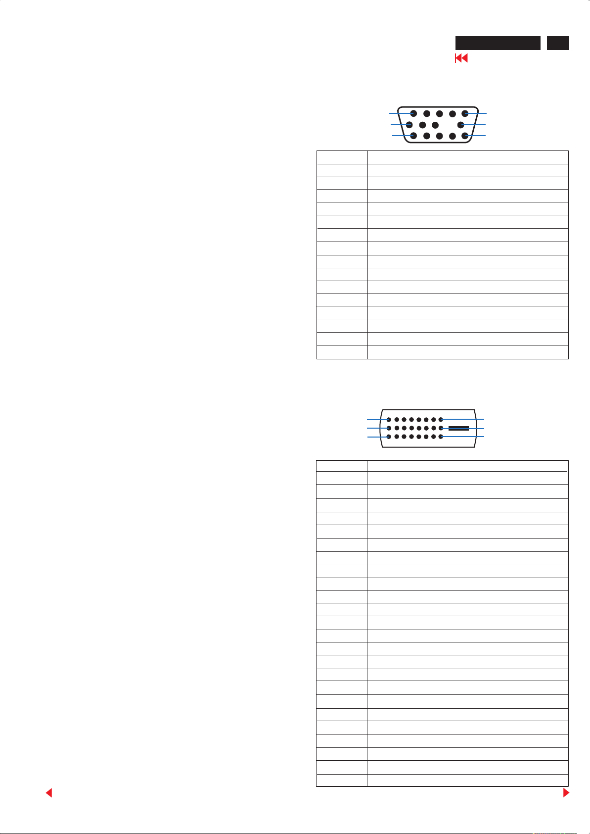
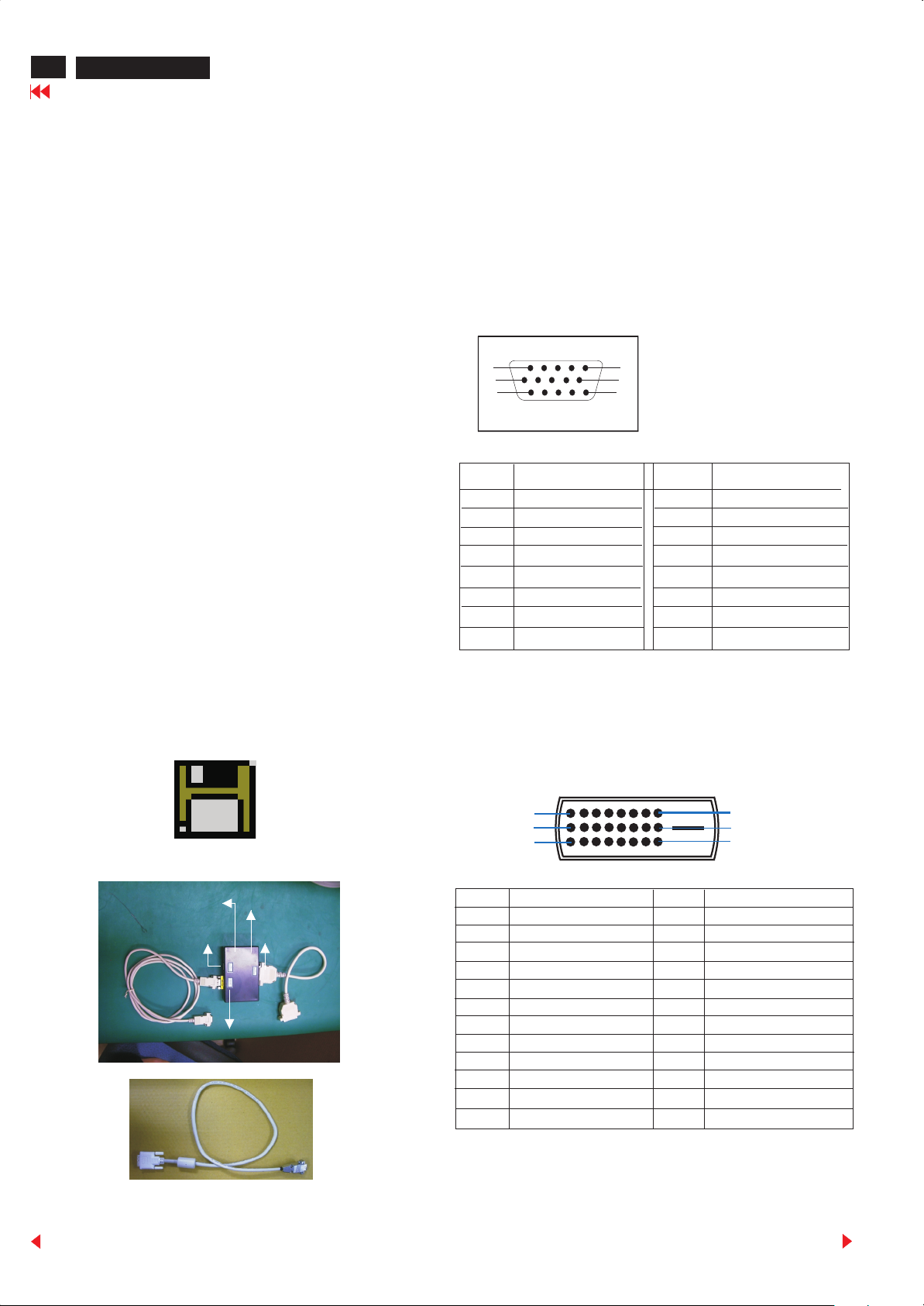
Pin Assignment
D-Sub connector
1
6
11
Pin No. Assignment
1 Red video input
2 Green video input / Sync On Green
3 Blue video input
4 Sense (ground)
5
6 Red video ground
7
8 Blue video ground
9 Not connected
10 Logic (Sync) ground
11 Sense (ground)
12 Bi-directional data (SDA of DDC)
13 H / H+V Sync
14 V. Sync (VCLK of DDC)
15 Data clock (SCL of DDC)
No connected
Green video ground
5
10
15
Physical Characteristics
Connector type : DVI-D, 15-pin D-subminiature
Signal cable type : Detachable
Tilt and swivel angle of pedestal
Tilt angle of forward : 0 degree
Tilt angle of backward : 30 degree
Swivel angle of left : 40 degree
Swivel angle of right : 40 degree
Dimensions
Height : 452 mm
Depth : 180 mm
Width : 454 mm
Weight (monitor only) : 7.2 kg
Temperature
Operating : 5 C to 35 C (41 F to 95 F)
Non-operating : -20 C to 60 C (-43 F to 140 F)
Humidity
Operating : 80% max. (non-condensing)
Non-operating : 95% max. (non-dondensing)
Altitude
Operating : 3,658 m
Non-operating : 12,192 m
Back
DVI-D connector
(Digital Visual Interface - Digital)
1
9
17
Pin No. 24-Pin Side of the Signal Cable
1 TMDS Data 2-
2 TMDS Data 2+
3 TMDS Data 2/4 Shield
4 TMDS Data 4-
5
6 DDC Clock
7
8 No connection
9 TMDS Data 1-
10 TMDS Data 1+
11 TMDS Data 1/3 Shield
12 TMDS Data 3-
13 TMDS Data 3+
14 +5V Power
15 Ground (+5)
16 Hot Plug Detect
17 TMDS Data 0-
18 TMDS Data 0+
19 TMDS Data 0/5 Shield
20 TMDS Data 5-
21 TMDS Data 5+
22 TMDS Clock Shield
23 TMDS Clock+
24 TMDS Clock-
TMDS Data 4+
DDC Data
8
16
24
Forward
4
170B LCD
Go to cover page
Technical Data
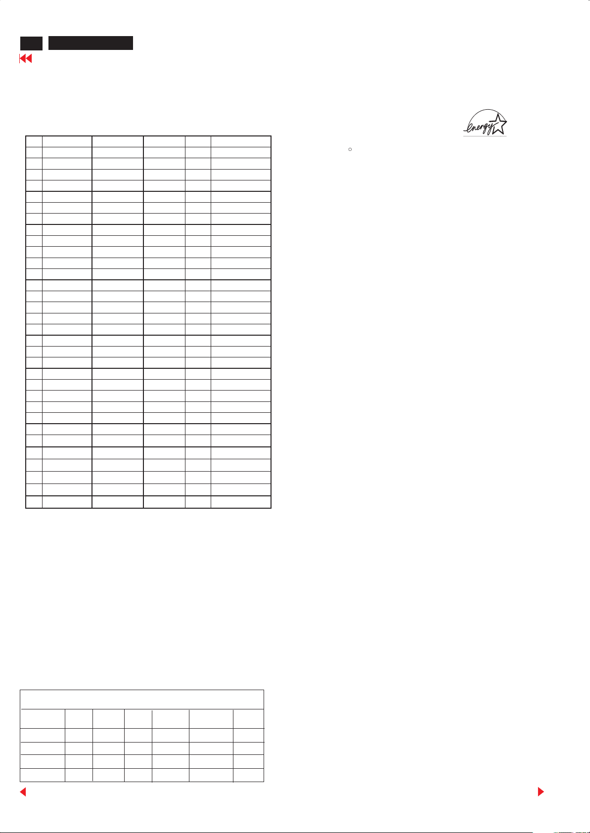
Data Storage
Factory preset mode:
This monitor has 16 factory-preset modes as indicated in the
following table :
# Resolution Frequency Pixel rate Sync Comment
1 640X350 31.5K/70HZ 25.175 (+/-) IBM VGA 10h
2 720X400 31.5K/70HZ 28.322 (-/+) IBM VGA 3h
3 640X480 37.5K/75HZ 31.501 (-/-)
4 640X480 43.3K/85HZ 36 (-/-)
5 640X480 37.9K/72HZ 31.5 (-/-)
6 640X480 35.0K/67HZ 30.24 (-/-)
7 640X480 31.5K/60HZ 25.175 (-/-)
8 800X600 35.2K/56HZ 36 (+/+)
9 800X600 46.9K/75HZ 49.498 (+/+)
10 800X600 37.9K/60HZ 40 (+/+)
11 800X600 53.7K/85HZ 56.251 (+/+)
12 832X624 49.7K/75HZ 57.28 (+/+) MAC
13 800X600 48.1K/72HZ 50 (+/+)
14 1024X768 60.0K/75HZ 78.75 (+/+)
15 1024X768 48.4K/60HZ 65 (-/-)
16 1024X768 56.5K/70HZ 75 (-/-)
17 1024X768 61.1K/76HZ 83.096 (+/+) IBM XGA-2
18 1024X768 68.7K/85HZ 94.5 (+/+)
19 1152X864 67.5K/75HZ 108 (+/+)
20 1152X864 63.9K/70HZ 94.5 (+/+) non-VESA
21 1152X864 54.0K/60HZ 79.9 (+/+) non-VESA
22 1152X870 68.7K/75HZ 100 (-/-) MAC
23 1152X900 61.8K/66HZ 92.94 serr- SUN Mode IV
24 1152X900 71.8K/76HZ 108 (+/+) SUN Mode II
25 1280X960 60.0K/60HZ 108 (+/+)
26 1280X960 75.0K/75HZ 129.895 (+/+) non-VESA
27 1280X1024 76.0K/72HZ 130.223 (+/+) DOS/V
28 1280X1024 64.0K/60HZ 108 (+/+)
29 1280X1024 80.0K/75HZ 135 (+/+)
30 1280X1024 81.1K/76HZ 135.008 (-/-) SUN Mode I
31 1280X1024 71.7K/67HZ 117 (+/+) SUN Mode V
32 688X556 31.3K/50HZ 27 (-/+) TV-PAL
This monitor is Environmental Protection Agency (EPA) Energy Star
compliant and TCO'99 power management compatible.
*Zero power consumption in OFF mode can only be achieved by
disconnecting the mains cable from the monitor.
ENERGY STAR is a U.S. registered mark. AS AN ENERGY STAR
R
PARTNER, PHILIPS HAS DETERMINED THAT THIS PRODUCT
MEETS THE ENERGY STAR GUIDELINES FOR ENERGY
EFFICIENCY.
Meanwhile, it also reverse 16 sets data space available for user
storage new timings data.
Automatic Power Saving
If you have VESA's DPMS compliance display card or software
installed in your PC, the monitor can automatically reduce power
consumption when power saving function active. And if an input
from keyboard, mouse or other input devices is detected, the
monitor will automatically "wake up". The following table shows
the power consumption and signaling of this automatic power
saving feature :
Power Management Definition
VESA's mode
ON
Stand-by
Suspend
OFF
Back
VIDEO
Active
Blanked
Blanked
Blanked
H-SYNC
Yes
No
Yes
No
V-SYNC
Yes
Yes
No
No
POWER
USED
< 42 W
< 3 W
< 3 W
< 3 W
POWER
SAVING( % )
0 %
83.3 %
83.3 %
90 %
LED
COLOR
Green
Amber
Amber
Amber
Forward
10
170B LCD
Go to cover page
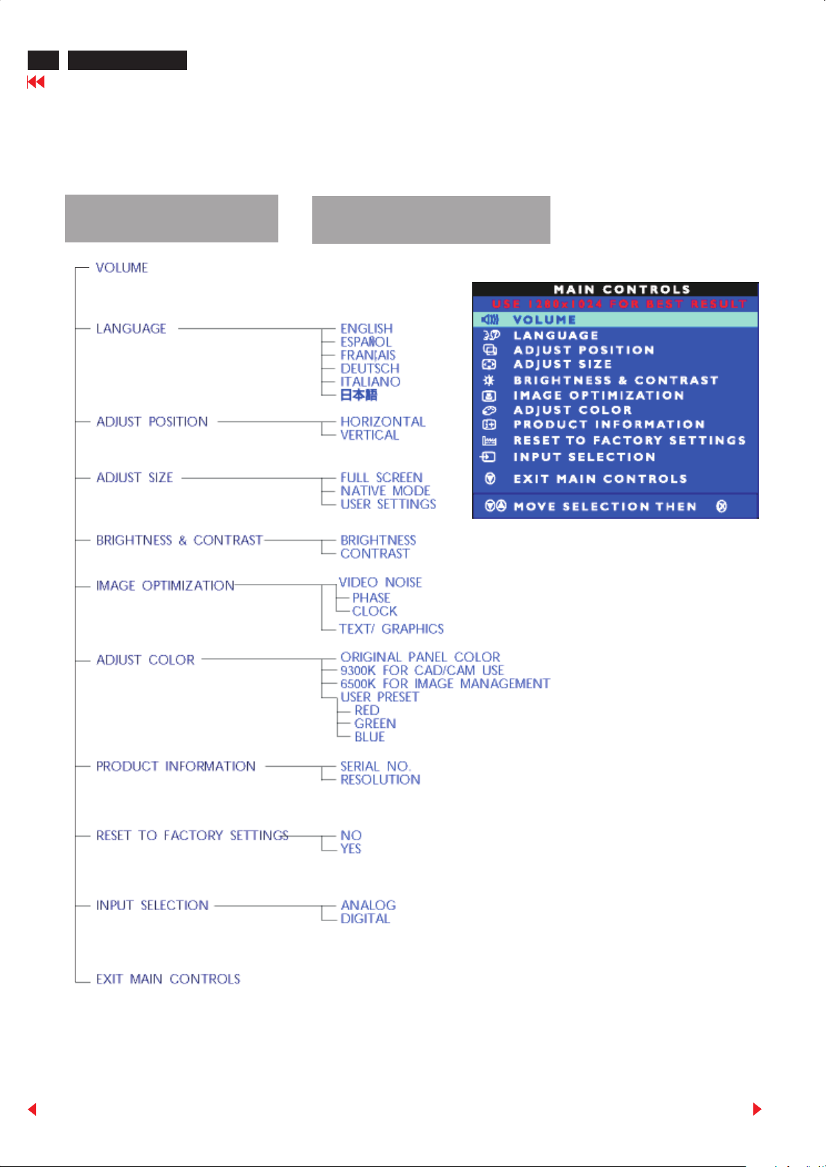
OSD Control Structure for Analog
The OSD Tree for analog video signal
Below is an overall view of the structure of the On-Screen Display. You can use this as reference when you want to later on work your way around the
different adjustments.
First Level
Second Level
OSD Menu (Analog)
Back
Forward
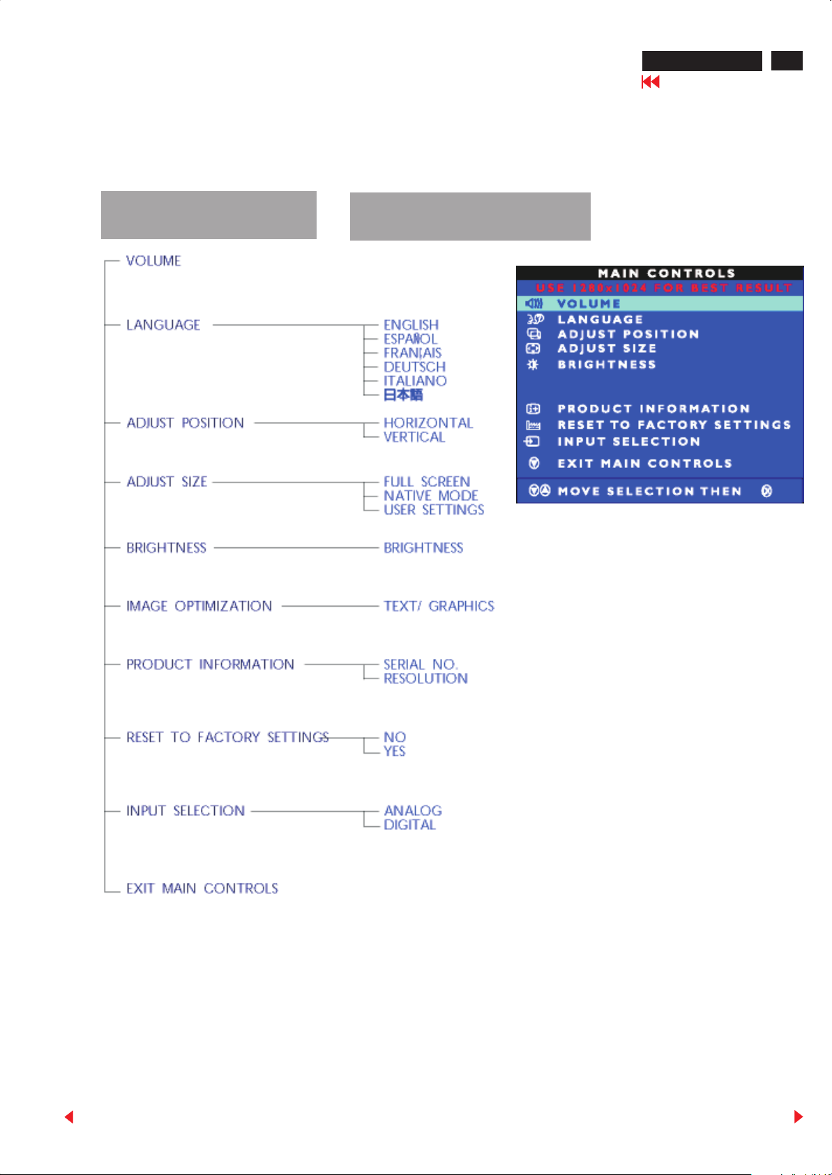
OSD Control Structure for Digital
170B LCD
Go to cover page
11
The OSD Tree for digital video signal (DVI-D)
This OSD structure is different from analog menu, there are three functions will be disable on digital OSD menu: Contrast, Image Optimization, and
Adjust Color.
First Level
Second Level
OSD Menu (Digital)
Back
Forward

12
170B LCD
Go to cover page
OSD Attention signals
The monitor will detect various display situation automatically. When
the monitor detects the problems, the screen will show the different
warning signals to remind you what is happen to your monitor.
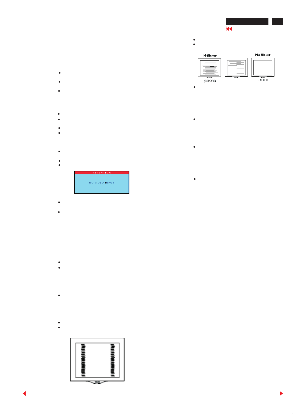
NO VIDEO INPUT
This screen appears if there is no video signal input. Please check
that the signal cable is properly connected to the video card of PC.
ATTENTION
NO VIDEO INPUT
VIDEO INPUT SELECTED
This windows appears 3 seconds that show you which video input
has selected by monitor when every time you turn on the monitor.
ATTENTION
ANALOG VIDEO INPUT SELECTED
USE OSD MENU TO CHANGE
DEFAULT INPUT SELECTION
ENTERING SLEEP MODE
This screen appears when the monitor is about to enter the sleep
mode. Please press any key on the keyboard or click the mouse to
wake up the monitor and computer.
ATTENTION
ENTERING SLEEP MODE
THIS IS BEST PICTURE SHARP
When you expand picture size by using OSD menu “ADJUST
SIZE/USER SETTINGS”, during the adjustment, Once the pixels
number of horizontal size has reached 1280 pixels, following
window will appear on the screen that remind you the resolution of
video signal was expanded exactly can match the LCD panel
(1280X1024).
ATTENTION
THIS IS BEST PICTURE SHAPE
CANNOT DISPLAY THIS VIDEO MODE..
This screen warns when the input frequency from the computer is not
a standard video mode or out of the monitor's scanning range.
Please change the display mode of the operating software in the
computer(i.e. Windows) to 1280 x 1024@ 60Hz for best display
results.
ATTENTION
CANNOT DISPLAY THIS VIDEO
MODE, CHANGE COMPUTER DISPLAY
INPUT TO 1280 X1024@60HZ
91.1 KHz 85.0Hz
In this case, the picture will still showing on the screen about 60
seconds then shut down by monitor. Attention message will
disappear as well after 30 minutes remaining then enter power
saving state. (No picture, power indicator showing amber.)
USE 1280 X 1024 FOR BEST RESULT
This message appears at the top of the OSD window when the video
mode input is not the recommended 1280x1024. Other modes may
result in some picture distortion. Please adjust the video mode to
1280x1024 at 60Hz for best display quality.
WAIT FOR AUTOMATIC ADJUSTMENT
This screen appears when you touch the button. It will
disappear when the monitor is properly adjusted.
ATTENTION
WAITING FOR AUTOMATIC
ADJUSTMENT
SECOND VODEO IS NOT AVAILABLE
When you select video input between Analog or Digital signal via
INPUT SELECTION function of OSD menu, if the one you are
selecting is not available, following message will appear on the
screen then switching back to the previous setting automatically.
ATTENTION
SECOND VIDEO
NOT AVAILABLE
USE 1280 x 1024 FOR BEST RESULT
Back
Forward
Trouble Shooting
170B LCD
Go to cover page
13
TROUBLESHOOTING
This page presents problems that can be corrected by the user. If the
problem still exists after these possible solutions, a further action has
to be take by authorized technicians.
No Picture
(Power LED not lit)
No Picture
(Power LED is
Amber or Yellow in
color)
Screen says
AUTO button not
working
properly
Make sure the Power cable is plugged to the
wall and back of the monitor.
Make sure the DC power cord has been
attached to the DC jack.
First, power button in front of the monitor
should be in the OFF position, then press it to
ON position again.
Make sure the computer is turned on.
Make sure the signal cable is properly
connected to your computer.
Check to see if the monitor cable has bent pins.
The Energy Saving Feature may be activated.
Make sure the monitor cable is properly
connected to your computer.
Check to see if the monitor cable has bent pins.
Make sure the computer is turned on.
The Auto Function is designed for
use on standard Macintosh or
IBM-compatible PC running Microsoft
Windows.
It may not work properly if using
non-standard PCs or video card.
Horizontal flicker
appears
The screen is too
bright or too dark
An after-image
appears
An after-image
remains after the
power has been
turned off
Green, red,
blue, dark and
white dots
remain on the
screen
Push the Auto button.
Eliminate the horizontal bars using the Phase
Adjustment in the First Window.
Adjust the contrast and brightness using the
First Window.
(The backlight of the LCD monitor has a fixed
life span. When the screen becomes dark or
begins to flicker,please contact your dealer.)
If an image remains in the screen for an
extended period of time,it may be imprinted in
the screen and leave an after-image. This
usually disappears after a few hours.
This is characteristic of liquid crystal and is
not caused by a malfunction or deterioration
of the liquid crystal. The after-image will
disappear after a set amount of time.
The remaining dots are normal
charactericstic of the liquid crystal used in
today's technology.
Imaging
Problems
Display position
is incorrect
Image vibrates
on the screen
Vertical flicker
appears
Push the AUTO button.
Adjust the image position using the Horizontal
Position & / or Vertical Position in the Second
Window.
Check that the signal cable is properly
connected to the graphics board or PC.
Push the AUTO button.
Eliminate the vertical bars using the Clock
Adjustment in the FIRST Window.
Back
Forward

14
Quick reference for failure mode of LCD panel
This page presents problems that could be made by LCD panel. It is
not necessary to repair circuit board. Simply follow the “Mechanical
instruction” on this manual to eliminate failure by replace LCD panel
or backlight tubes.
170B LCD
Go to cover page
Failure description Phenomenon
Failure Mode of LCD panel
Polarizer has bubbles
..
Vertical block defect
Vertical dim lines
Vertical lines defect
(Always bright or dark)
Horizontal block defect
Polarizer has bubbles
. .. .
Foreign material inside
polarizer. It shows linear or
dot shape.
Concentric circle formed
Horizontal dim lines
Horizontal lines defect
(Always bright or dark)
Has bright or dark pixel
Bright pixel
.
.
..
..
Dark pixel
.
.
.
.
.
.
Bottom back light of LCD is
brighter than normal
Backlight un-uniformity
Backlight has foreign
material. Black or white
color, linear or circular type
. .. .
Back
Forward
16
170B LCD
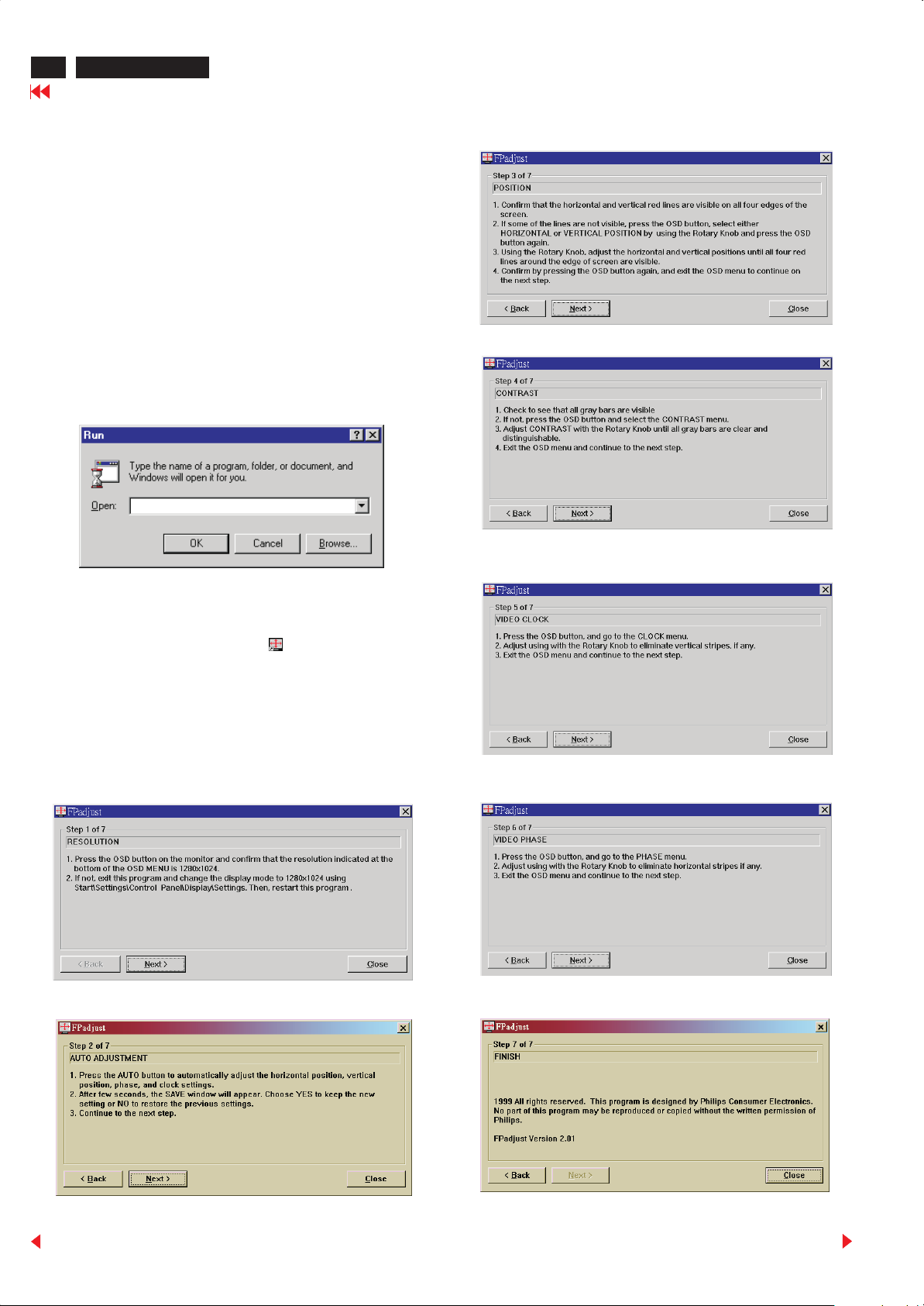
Flat Panel Adjust (FP Adjust)
Go to cover page
Fpadjust program
The Flat Panel Adjust (FPadjust) software helps you to find the best
setting for your Philips LCD monitor. It allows you to adjust the image
performance of LCD monitor, such as RESOLUTION,
AUTO ADJUSTMENT, POSITION, CONTRAST, IMAGE OPTIMIZATION.
Note: Image optimization function is only available for analog video
signals.
Install and Run FPadjust
In "MS Windows 95/98" environment : For example
1. Insert CD-DFU(3138 117 01953) to your CD-ROM driver.
2. Run "E:\PC\FPADJUST\SETUP.EXE" as Fig. 1. (Replace E by the
letter of your CD-ROM driver)
E:\PC\FPADJUST\SETUP.EXE
Fig. 1
3. Then follow the instructions to install the FPadjust program.
When finish, double click FPadjust icon " ", then the
description (can be moved by mouse) and background pattern
come on the screen for image adjustment.
FPadjust program is working as a pattern generator to provide the
pattern display on the screen for the adjustment of CONTRAST,
CLOCK, PHASE ...etc. Please follow the steps below to adjust your
PHILIPS Flat Panel Monitor for best display quality.
FPadjust.lnk
Back
Forward
Definition of Pixel Defects
170B LCD
Go to cover page
17
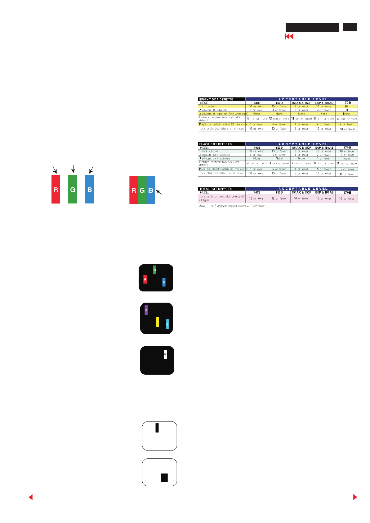
0. General
This section explains the different types of pixel defects and
defines acceptable defect levels of each type. In order to qualify
for repair or replacement under warranty, the number of pixel
defects on a TFT LCD panel must exceed these acceptable levels.
1. Definition of Pixels and Subpixels
A pixel, or picture element , is composed of three subpixels in the
primary colors of red, green and blue. Many pixels together from
an image. When all subpixels of a pixel are lit, the three colored
subpixels together appear as a single white pixel. When all are
dark, the three colored subpixels together appear as a single black
pixel. Other combinations of lit and dark subpixels appear as
single pixels of other colors.
Subpixel
Subpixel
Subpixel
Pixel
2. Types of Pixel Defects
Pixel and subpixel defects appear on the screen in different ways.
3. Pixel Defect Tolerances
In order to qualify for repair or replacement due to pixel defects
during the warranty period, a TFT LCD panel in a PHILIPS flat
panel monitor must have pixel or subpixel defects exceeding the
tolerances listed in the following tables.
Bright dot defects
Bright dot defects appear as pixels or subpixels that are always lit
or “On”. These are the types of bright dot defects:.
One lit red, green or blue subpixel
Two adjacent lit subpixels:
- Red + Blue = Purple
- Red + Green = Yellow
- Green + Blue = Cyan (Light Blue)
Three adjacent lit subpixels
(One white pixel)
Black dot defects
Black dot defects appear as pixels or subpixels that are always
dark or “off”. These are the types of black dot defects:
One dark subpixel
Two or three adjacent dark subpixels
Back
Forward
18
170B LCD
Go to cover page
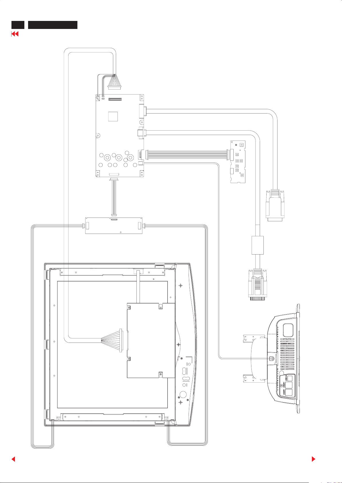
1013
MAIN BOARD
Wiring Diagram
1012
1302
1301
1201
1261
1910
1909
CONTROL BOARD
LCD PANEL
INVERTER BOARD
Back
Forward
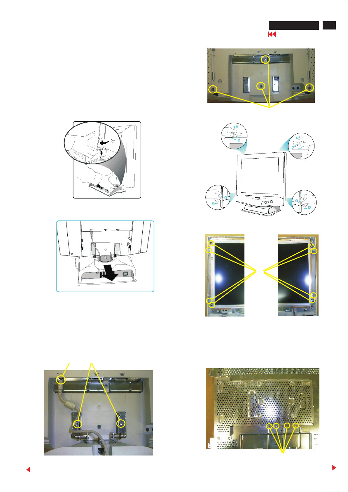
Mechanical instructions
General
To be able to perform measurements and repairs on the circuit
boards, Spread a soft mat underneath to avoid damaging the LCD
surface.
1. Rear cover removal
170B LCD
Go to cover page
19
Step 1 : To remove the back cover, press up to disengage the clips
on each side, then pull and lift as shown in Fig.1
Step 2 : Remove plastic ring from the hinge. See Fig. 2
Fig. 1
(C)
Fig. 4
Fig. 5
Fig. 2
2. LCD panel removal and Fluorescent lamp
replacement
Step 1 : Remove two screws (A) and unplug 18VDC power
connector (B). See Fig. 3
Step 2 : Remove four screws (C). See Fig. 4
Step 3 : Remove protective cover. See Fig. 5
Step 4 : Remove eight screws (D). See Fig. 6
(A)(B)
(D)
Fig. 6
Step 5 : Remove four screws (E). See Fig.7
Step 6 : Disconnect five connectors (F). See Fig. 8
Step 7 : Remove two screws (G). Draw out upper and lower lamp
set. See Fig. 9
Back
Fig. 3
Fig.7
(E)
Forward

20
170B LCD
Go to cover page
Mechnical instructions
4. Inverter PCB removal
(F)
Fig. 8
Note: The fluorescent lamps
are consumable. When replace
the lamps, both upper and lower
fluorescent lamps should be
replaced in all cases. If only one
lamp is replaced on either side,
there can be unevenness in the
brightness.
(G)
Step 1 : Disconnect three connectors (A) and remove screw (B).
See Fig. 12
(A)
(B)
Fig. 12
5. Disassemble the pedestal
Step 1 : Remove two screws ( C). See Fig. 2
Step 2 : Disconnect one connector (E), remove two screws (D),
release three clips (F). See Fig. 3
(C)
Fig. 9
3. Main panel and inverter panel removal
Step 1 : Disconnect three connectors (H). See Fig. 10
Step 2 : Remove seven screws (I). See Fig. 10
(H)
Fig. 10
(I)
Fig. 2
Back
Forward

(F)
Mechanical instructions
170B LCD
Go to cover page
21
(E)
Recommended service position
(D)
Fig. 3
Back
Forward
22
170B LCD
Go to cover page
Electrical instructions
0. General
When carry-out the electrical settings in many cases a video
signal must be applied to the monitor. A computer with :
- ATI VGA 1024 V6-1.04/PH BETA4 interface card
- PGA 1024 (4822 212 30916), Mach 8.
- PGA 1280 (4822 212 30917), Mach 32.
- ATI GPT-1600 (4822 397 10065), Mach 64 (up to 107kHz)
are used as the video signal source. The signal patterns are
selected from the "service test software" package, see user
guide 4822 727
19896 (ATI1024), or 4822 727 20273 (PGA 1280), or
4822 727 21046 (GPT-1600).
0.1 With normal VGA card:
If not using the ATI card during repair or alignment, The service
engineer also can use this service test software adapting with
normal standard VGA adaptor and using standard VGA mode
640 x 480, 31.5 kHz/60 Hz (only) as signal source.
0.2 AC/DC Measurement:
The measurements for AC waveform and DC figure is based on
640 x 480 31.5 kHz/60 Hz resolution mode with test pattern "gray
scale".
1.General points
1.1 During the test and measuring, supply a distortion free AC mains
voltage to the apparatus via an isolated transformer with low
internal resistance.
1.2 All measurements mentioned hereafter are carried out at a
normal mains voltage (90 - 132 VAC for USA version, 195 -264
VAC for EUROPEAN version, or 90 - 264 VAC for the model with
full range power supply, unless otherwise stated.)
1.3 All voltages are to be measurement or applied with respect to
ground, unless otherwise stated. Note: don't use heat-sink as
ground.
1.4 The test has to be done on a complete set including LCD panel in
a room with temperature of 25 +/- 5 degree C.
1.5 All values mentioned in these test instruction are only applicable
of a well aligned apparatus, with correct signal.
PRESET VIDEO RESOLUTION
Factory preset video resolution
# Resolution Frequency Pixel rate Sync Comment
1 640X350 31.5K/70HZ 25.175 (+/-) IBM VGA 10h
2 720X400 31.5K/70HZ 28.322 (-/+) IBM VGA 3h
3 640X480 37.5K/75HZ 31.501 (-/-)
4 640X480 43.3K/85HZ 36 (-/-)
5 640X480 37.9K/72HZ 31.5 (-/-)
6 640X480 35.0K/67HZ 30.24 (-/-)
7 640X480 31.5K/60HZ 25.175 (-/-)
8 800X600 35.2K/56HZ 36 (+/+)
9 800X600 46.9K/75HZ 49.498 (+/+)
10 800X600 37.9K/60HZ 40 (+/+)
11 800X600 53.7K/85HZ 56.251 (+/+)
12 832X624 49.7K/75HZ 57.28 (+/+) MAC
13 800X600 48.1K/72HZ 50 (+/+)
14 1024X768 60.0K/75HZ 78.75 (+/+)
15 1024X768 48.4K/60HZ 65 (-/-)
16 1024X768 56.5K/70HZ 75 (-/-)
17 1024X768 61.1K/76HZ 83.096 (+/+) IBM XGA-2
18 1024X768 68.7K/85HZ 94.5 (+/+)
19 1152X864 67.5K/75HZ 108 (+/+)
20 1152X864 63.9K/70HZ 94.5 (+/+) non-VESA
21 1152X864 54.0K/60HZ 79.9 (+/+) non-VESA
22 1152X870 68.7K/75HZ 100 (-/-) MAC
23 1152X900 61.8K/66HZ 92.94 serr- SUN Mode IV
24 1152X900 71.8K/76HZ 108 (+/+) SUN Mode II
25 1280X960 60.0K/60HZ 108 (+/+)
26 1280X960 75.0K/75HZ 129.895 (+/+) non-VESA
27 1280X1024 76.0K/72HZ 130.223 (+/+) DOS/V
28 1280X1024 64.0K/60HZ 108 (+/+)
29 1280X1024 80.0K/75HZ 135 (+/+)
30 1280X1024 81.1K/76HZ 135.008 (-/-) SUN Mode I
31 1280X1024 71.7K/67HZ 117 (+/+) SUN Mode V
32 688X556 31.3K/50HZ 27 (-/+) TV-PAL
3. AC Adaptor
3.1Setup the AC I/P at 90VAC, and Output DC loading at 4 Amp,
The DC output voltage is 18 1 V DC
3.2 DC setting
1003: all on (connect 3.3V,5V DC power to main board)
1005: all on (connect 12V DC power to main board)
4. Display Adjustment
4.1Input signals check
In factory mode, use 64 gray level and set the R,G,B sub gain to
100%.
4.2 Display quality test
Use timing mode as described in 2.2, and use the POPO (pixel on
pixel off) pattern to adjust the clock until no stripe and adjust the
phase until clear picture. Check all pre-setting 32 modes.
4.2.1 SOG mode test : Use following timing for SOG test
1.6 The letters symbols (B) and (S) placed behind the test instruction
denotes
(B): carried out 100% inspection at assembly line
(S): carried out test by sampling
1.7 The white balance (color temperature), has to be tested in
subdued lighted room.
1.8 Repetitive power on/off cycle are allowed except it should be
avoided within 6 sec.
2. Input signal
2.1 Signal type
Video : 0.7 Vp-p linear, positive polarity
Sync. : TTL level, separate, positive or negative polarity
Signal source: pattern generator format as attachment.
(table 1 to 16) Reference generator : CHROMA 2200 or 2250
2.2 Input signal mode
Pre-set 32 modes
Back
64 KHz/60Hz, 1280 X 1024, pixel=108 MHz
Horizontal Vertical
Frame border = 0 Frame border = 0
Total size = 15.620 us Total size = 16.670 ms
Display size = 11.852 us Display size = 16.000 ms
Rear porch = 2.000 us Rear porch = 0.580 ms
Sync width = 1.000 us Sync width = 0.080 ms
Sync polarity = - Sync polarity = Sync on green
4.3 Check of WHITE-D (B)
Apply a 80kHz/75Hz signal with white pattern, set brightness
control at 70%, and contrast control at 50%. Adjust the R, G, B
sub_gain, for the screen center, the 1931 CIE chromaticity (X,
Y) co-ordinates shall be;
9300 K 6500 K
x (center) 0.281 0.005 0.312
y (center) 0.311 0.338
0.005 0.005
0.005
Forward

Electrical instructions
Use Minolta CA-110 for color coordinates and luminance check.
Luminance; 200 Nits (ADT panel) in the center of the screen.
4.4 Check the digital interface
Set the delay time to be 6 nsec.
Check the 64 gray level color poor & noise condition.
170B LCD
Go to cover page
23
Back
Forward

24
POGO2 V0.17 2000-05-09
AUTO SUB
9300K R G B
6500K R G B
OFFSET R G B
SUB CON
OK
POGO2 V0.17 2000-05-09
9300K R G B
6500K R G B
OFFSET R G B
SUB CON
GAIN R G B
GAIN R G B
170B LCD
Go to cover page
Factory Adjustment
Factory Mode Adjustment
Entering Factory Adjustment Menu
Push & buttons then power on the monitor, release them
after picture display normally. Press button to bring up OSD
menu of factory mode as shown below.
POGO2 V0.17 2000-05-09
Use button to select factory adjustment indication (for example:
POGO2 V0.17 2000-05-09), which is the entrance of the factory
adjustment menu, press button to access it. The window shows
as below.
POGO2 V0.17 2000-05-09
(PS: The “Offset R G B” function can be used on reduce or eliminate
snowy noise on the background when the resolution of video signal is
1024 X 768 vertical 60Hz. Slightly increase or decrease the value
until snowy noise completely disappear.)
PRESET VIDEO RESOLUTION
AUTO SUB
-
9300K R G B
6500K R G B
OFFSET R G B
GAIN R G B
Use or buttons to select SUB-CON, 9300K R G B,..etc.
Use or buttons to decrease/increase the value of each item
: adjust Sub-brightness & Sub-contrast automatically.
AUTO
AUTO SUB
9300K R G B
6500K R G B
OFFSET R G B
GAIN R G B
Contrast adjustment (Sub-Contrast). Use this menu item to
9 3 0 0 K R G B
6 5 0 0 K R G B
Color temperature gain adjustment. Use these menu items to
adjust the contrast gain of pre-amp ranges from 0 to 255.
adjust the RGB gains of pre-amp for different color
temperatures, ranges from 0 to 255.
POGO2 V0.17 2000-05-09
-
205
255
22
OK
SUB CON
OK
SUB CON
233
255
20
-
-
166
255
149
20
OFFSET R G B
Sub-Brightness adjustment. Use this menu item to adjust
the brightness level (DC-level) of pre-amp range from 0 to
255.
Back
Forward
26
170B LCD
Go to cover page
DDC Instructions
1. General
DDC Data Re-programming
In case the DDC data memory IC or main EEPROM which storage all
factory settings were replaced due to a defect, the serial numbers have
to be re-programmed.
It is advised to re-soldered DDC IC and main EEPROM from the old
board onto the new board if circuit board have been replaced, in this
case the DDC data does not need to be re-programmed.
Additional information
Additional information about DDC (Display Data Channel) may be
obtained from Video Electronics Standards Association (VESA).
Extended Display Identification Data(EDID) information may be also
obtained from VESA.
DDC EDID structure
For Analog interface: Standard Version 3.0
Structure Version 1.3
For Digital inferface: Standard Version 3.0
Structure Version 1.3
2. System and equipment requirements
1. An i486 (or above) personal computer or compatible.
2. Microsoft operation system Windows 95/98.
3. EDID30.EXE program (3138 106 10075) shown as Fig. 1
4. A/D Alignment kits (3138 106 10079) shown as Fig. 2. This kit
contents: a. Alignment box x1
b. Printer cable x1
c. D-Sub cable x1
d. (DVI-D) to (D-Sub) cable x1
Note: The alignment box has already build-in a batteries socket for
using batteries (9V) as power source. Pull out the socket by
remove four screws at the rear of box. Please do not forget that
remove batteries after programming. The energy of batteries can
only drive circuits for a short period of time.
3. Pin assignment
A. 15-pin D-Sub Connector
1
6
11
Pin No.
Assignment
1
Red video input
Green video input
2
Blue video input
3
Ground
4
No Connected
5
Red video ground
6
Green video ground
7
8
Blue video ground
PRESET VIDEO RESOLUTION
5
10
15
Pin No.
9
10
11
12
13
14
15
Assignment
+5V
Ground
Ground
Serial data line(SDA)
H.Sync
V.Sync(VCLK for DDC)
Data clock line(SCL)
Note: The EDID30.EXE (Release Version 1.5 1999.11.17)is a
windows-based program, which cannot be run in MS-DOS.
Meanwhile, it is also fully compatible with previous programs
DDCV2X.EXE series(MS-DOS based).
EDID30.EXE
Ver:1.5
Figure 1
Diskette with EDID30.EXE
DC 8V~12V
To Monitor
Power indicator
To Printer
Video Card
B. DVI-D Connector
1
9
17
Pin No. Assignment Pin No. Assignment
1 TMDS Data 2- 13 TMDS Data 3+
2 TMDS Data 2+ 14 +5V Power
3 TMDS Data 2/4 Shield 15 Ground (+5V)
4 TMDS Data 4- 16 Hot Plug Detect
5 TMDS Data 4+ 17 TMDS Data 06 DDC Clock 18 TMDS Data 0+
7 DDC Data 19 TMDS Data 0/5 Shield
8 No connect 20 TMDS Data 5-
9 TMDS Data 1- 21 TMDS Data 5+
10 TMDS Data 1+ 22 TMDS Clock Shield
11 TMDS Data 1/3 Shield 23 TMDS Clock+
12 TMDS Data 3- 24 TMDS Clock-
8
16
24
Back
(DVI-D) to (D-Sub) cable
Fig. 2 A/D Alignment Kits
Forward
DDC Instructions
170B LCD
Go to cover page
27
4. Configuration and procedure
There are three chips contained serial number on the circuit board,
Analog DDC IC (7301), Digital DDC IC (7302) and main EEPROM
(7204) which storage all factory settings. Following descriptions are the
connection and procedure for Analog DDC IC and Digital DDC IC, the
main EEPROM can be re-programmed along with Analog IC by enable
“factory memory data write” function on the DDC program
(EDID30.EXE).
Initialize alignment box
In order to avoid that monitor entering power saving mode due to
sync will cut off by alignment box, it is necessary to initialize
alignment box before running programming software (EDID30.EXE).
Following steps show you the procedures and connection.
Step 1: Supply 8~12V DC power source to the Alignment box by
plugging a DC power cord or using batteries.
Step 2: Connecting printer cable and video cable of monitor as Fig. A
Step 3: Run the EDID30.EXE program until the main menu appears.
This is for initialize alignment box.
PC
Rear view of 170B
DVI-DD-Sub
Re-programming Digital DDC IC
Connecting all cables and alignment box as shown on Fig. 4
Step 1:
Step 2: Press and hold “ “ and “ “ buttons then power on the
monitor.
Step 3: Follow the steps on DDC re-programing instructions to starting
re-programming.
PC
Rear view of 170B
DVI-DD-Sub
DC Power
8~12 V
~
~
To video card
To printer port (LTP1)
Printer
Port
DVI-D to D-Sub cable
To
Monitor
To PC
Fig. 4
DC Power
8~12 V
~
~
To video card
To printer port (LTP1)
Printer
Port
To
Monitor
To PC
Fig. A
Re-programming Analog DDC IC
Step 1: After initialize alignment box, connecting all cables and box as
Fig. 3
Step 2: Press and hold “ “ and “ “ buttons then power on the
monitor.
Step 3: Follow the steps on DDC re-programming instructions to staring
re-programming.
Rear view of 170B
PC
DVI-DD-Sub
5. DDC re-programming instructions
Start on DDC program
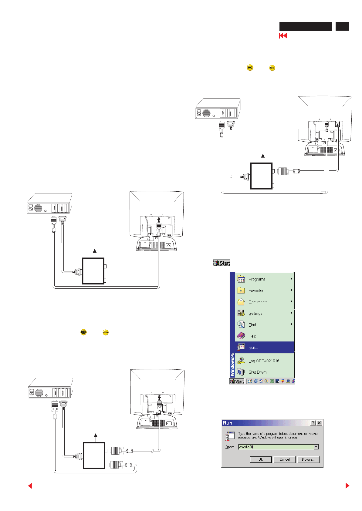
Start Microsoft Windows.
1. Insert the disk containing EDID30.EXE program into floppy disk drive.
2. Click , choose Run at start menu of Windows 95/98.
3. At the submenu, type the letter of your computer's floppy disk drive
followed by :EDID30 (for example, A:\EDID30, as shown in Fig. 5).
Back
To video card
To printer port (LTP1)
DC Power
8~12 V
~
~
To
Monitor
Printer
Port
To PC
Fig. 3
Fig. 5
Forward

28
170B LCD
DDC Instructions
Go to cover page
4. Click button. The main menu appears (as shown on Fig. 6).
Command bar
Tools bar
Status bar
Fig. 6
Note: If the connection is improper, you will see the following error
message before entering the main menu. Meanwhile, the
(read EDID) function will be disable. At this time, please make
sure all cables are connected correctly and fixedly, and the
procedure has been performed properly.
Note: During the loading, EDID30 will verify the EDID data which just
loaded from monitor before proceed any further function, once
the data structure of EDID can not be recognized, the following
error message will appear on the screen (Fig. 8). Please confirm
following steps to avoid this message.
1. The data structure of EDID was incorrect.
2. DDC IC that you are trying to load data is empty.
3. Wrong communication channel has set at configuration setup
windows.
4. Cables loosed or poor contact of connection.
Loading DDC data from monitor
1. Click icon on the tools bar to bring up the Configuration Setup
windows as Fig.7
2. Select the DDC2B as the communication channel.
3. Enable Factory memory data write function and fill in page address
“F0” to the block.
4.. Click button to confirm your selection.
Note: The Factory memory data write function will allow EDID30 to
rewrite serial numbers both Analog DDC IC and main EEPROM to
make sure both S/N are exactly the same. You may confirm the
function by checking the S/N at Product information of the OSD
menu after restarting the monitor.
Fig. 7
Fig. 8
Modify DDC data (Serial No.)
1. Click icon on the tools bar.
2. Click till the Step 7 of 9 window appears.
3. Type the new Serial No. (for example, Tw9928000001).
4. Click till the last step window appears, then click to
exit the Step window.
Tw9928000001
5. Click icon to read DDC EDID data from monitor. The EDID
codes will display on screen as following. (The EDID codes are
depend on the model.) Meanwhile, The status bar will indicate 00%
to 100% when reading.
Back
Forward

DDC Instructions
170B LCD
Go to cover page
29
Write DDC data to monitor
1. Click icon from the tools bar to starting rewrite DDC data.
2. Click for confirmation.
Save DDC data as a file
Sometimes, you maybe need to save DDC data as a text file for using
on other DDC chip. To save DDC data, follow the steps below:
1. Click icon on the tools bar and type a file name you like. The
file format is ddc type which can be open by Microsoft WordPad.
2. Click button.
Load DDC data from file
1. Click from the tools bar.
2. Select the file you want to open.
3. Click . Button.
Definition of Serial Number
T Y 0 0 9 9 2 8 0 0 0 0 0 1
Serial Number (U.S.A: 8 digit)
Week
Year
TY Code
TY----Chungli
CX----Dong Guan
HD----Hungary
BZ----Suzhou
(Other regions: 6 digit)
4. Now you can re-programming DDC data which you just loaded
from a file, please be confirmed that model and serial number are
correct and match with the monitor you are trying to re-write.
Exit DDC program
1. Click file command on the command bar then select Exit.
Back
Forward

30
170B LCD
Go to cover page
DDC data of Analog
THE DISPLAY DATA CHANNEL ( DDC ) 1/2B CONTENT INCLUDING
(FOR ADT ANALOG)
Vendor/Product Identification
ID Manufacturer Name : PHL
ID Product Code : 170B (HEX.)
ID Serial Number : 123456 (DEC.)
Week of Manufacture : 29
Year of Manufacture : 2000
EDID Version, Revision
Version : 1
Revision : 3
Basic Display Parameters/Features
Video Input Definition : Analog Video Input
0.700V/0.300V (1.00Vpp)
Without Blank-to-Black Setup
Separate Sync
Composite Sync
Sync on Green
No Serration required
Maximum H Image Size : 34
Maximum V Image Size : 27
Display Transfer Characteristic : 2.1
(gamma)
Feature Support (DPMS) : Standby
Suspend
Active Off
Display Type : RGB color display
Preferred Timing mode : Detailed timing block 1
Color Characteristics
Red X coordinate : 0.63
Red Y coordinate : 0.33
Green X coordinate : 0.30
Green Y coordinate : 0.60
Blue X coordinate : 0.15
Blue Y coordinate : 0.10
White X coordinate : 0.31
White Y coordinate : 0.33
Established Timings
Established Timings I : 720 x 400 @70Hz (IBM,VGA)
640 x 480 @60Hz (IBM,VGA)
640 x 480 @67Hz (Apple,Mac II)
640 x 480 @72Hz (VESA)
640 x 480 @75Hz (VESA)
800 x 600 @56Hz (VESA)
800 x 600 @60Hz (VESA)
Established Timings II : 800 x 600 @72Hz (VESA)
800 x 600 @75Hz (VESA)
832 x 624 @75Hz (Apple,Mac II)
1024 x 768 @60Hz (VESA)
1024 x 768 @70Hz (VESA)
1024 x 768 @75Hz (VESA)
1280 x 1024 @75Hz (VESA)
Manufacturer's timings : 1152 x 870 @75Hz (Apple,Mac II)
Standard Timing Identification #1
Horizontal active pixels : 640
Aspect Ratio : 4:3
Refresh Rate : 85
Standard Timing Identification #2
Horizontal active pixels : 800
Aspect Ratio : 4:3
Refresh Rate : 85
Standard Timing Identification #3
Horizontal active pixels : 1024
Aspect Ratio : 4:3
Refresh Rate : 85
Back
Standard Timing Identification #4
Horizontal active pixels : 1024
Aspect Ratio : 4:3
Refresh Rate : 75
Standard Timing Identification #5
Horizontal active pixels : 1152
Aspect Ratio : 4:3
Refresh Rate : 70
Standard Timing Identification #6
Horizontal active pixels : 1152
Aspect Ratio : 4:3
Refresh Rate : 75
Standard Timing Identification #7
Horizontal active pixels : 1280
Aspect Ratio : 5:4
Refresh Rate : 60
Detailed Timing #1
Pixel Clock (MHz) : 135
H Active (pixels) : 1280
H Blanking (pixels) : 408
V Active (lines) : 1024
V Blanking (lines) : 42
H Sync Offset (F Porch) (pixels) : 248
H Sync Pulse Width (pixels) : 144
V Sync Offset (F Porch) (lines) : 38
V Sync Pulse Width (lines) : 3
H Image Size (mm) : 337
V Image Size (mm) : 270
H Border (pixels) : 0
V Border (lines) : 0
Flags : Non-interlaced
: Normal Display, No stereo
: Digital Separate sync.
: Positive Vertical Sync.
: Positive Horizontal Sync.
Monitor Descriptor #2
Serial Number : TY 123456
Monitor Descriptor #3
Monitor Name : PHILIPS 170B
Monitor Descriptor #4
Monitor Range Limits
Min. Vt rate Hz : 56
Max. Vt rate Hz : 75
Min. Horiz. rate kHz : 30
Max. Horiz. rate kHz : 82
Max. Supported Pixel : 140
No secondary GTF timing formula supported.
Extension Flag : 0
Check sum : 0E (HEX.)
**********************************************************************
EDID data (128 bytes)
**********************************************************************
0: 00 1: ff 2: ff 3: ff 4: ff 5: ff 6: ff 7: 00
8: 41 9: 0c 10: 0b 11: 17 12: 56 13: 34 14: 12 15: 00
16: 1d 17: 0a 18: 01 19: 03 20: 0f 21: 22 22: 1b 23: 6e
24: ea 25: 6e 26: a6 27: a1 28: 54 29: 4c 30: 99 31: 26
32: 19 33: 4f 34: 54 35: bf 36: ef 37: 80 38: 31 39: 59
40: 45 41: 59 42: 61 43: 59 44: 61 45: 4f 46: 71 47: 4a
48: 71 49: 4f 50: 81 51: 80 52: 01 53: 01 54: bc 55: 34
56: 00 57: 98 58: 51 59: 00 60: 2a 61: 40 62: f8 63: 90
64: 63 65: 08 66: 51 67: 0e 68: 11 69: 00 70: 00 71: 1e
72: 00 73: 00 74: 00 75: ff 76: 00 77: 54 78: 59 79: 20
80: 20 81: 31 82: 32 83: 33 84: 34 85: 35 86: 36 87: 0a
88: 20 89: 20 90: 00 91: 00 92: 00 93: fc 94: 00 95: 50
96: 48 97: 49 98: 4c 99: 49 100: 50 101: 53 102: 20 103: 31
104: 37 105: 30 106: 42 107: 0a 108: 00 109: 00 110: 00 111: fd
112: 00 113: 38 114: 4b 115: 1e 116: 52 117: 0e 118: 00 119: 0a
120: 20 121: 20 122: 20 123: 20 124: 20 125: 20 126: 00 127: 0e
Forward

DDC data of Digital
170B LCD
Go to cover page
31
THE DISPLAY DATA CHANNEL ( DDC ) 1/2B CONTENT INCLUDING
(FOR ADT DIGITAL)
Vendor/Product Identification
ID Manufacturer Name : PHL
ID Product Code : 170B (HEX.)
ID Serial Number : 123456 (DEC.)
Week of Manufacture : 29
Year of Manufacture : 2000
EDID Version, Revision
Version : 1
Revision : 3
Basic Display Parameters/Features
Video Input Definition : Digital Video Input
Compatible with VESA DFP 1.x
Maximum H Image Size : 34
Maximum V Image Size : 27
Display Transfer Characteristic : 2.1(gamma)
Feature Support (DPMS) : Standby
Suspend
Active Off
Display Type : RGB color display
Preferred Timing mode : Detailed timing block 1
Color Characteristics
Red X coordinate : 0.63
Red Y coordinate : 0.33
Green X coordinate : 0.30
Green Y coordinate : 0.60
Blue X coordinate : 0.15
Blue Y coordinate : 0.10
White X coordinate : 0.31
White Y coordinate : 0.33
Established Timings
Established Timings I : 720 x 400 @70Hz (IBM,VGA)
640 x 480 @60Hz (IBM,VGA)
640 x 480 @67Hz (Apple,Mac II)
640 x 480 @72Hz (VESA)
640 x 480 @75Hz (VESA)
800 x 600 @56Hz (VESA)
800 x 600 @60Hz (VESA)
Established Timings II : 800 x 600 @72Hz (VESA)
800 x 600 @75Hz (VESA)
832 x 624 @75Hz (Apple,Mac II)
1024 x 768 @60Hz (VESA)
1024 x 768 @70Hz (VESA)
1024 x 768 @75Hz (VESA)
1280 x 1024 @75Hz (VESA)
Manufacturer's timings : 1152 x 870 @75Hz (Apple,Mac II)
Standard Timing Identification #1
Horizontal active pixels : 640
Aspect Ratio : 4:3
Refresh Rate : 85
Standard Timing Identification #2
Horizontal active pixels : 800
Aspect Ratio : 4:3
Refresh Rate : 85
Standard Timing Identification #3
Horizontal active pixels : 1024
Aspect Ratio : 4:3
Refresh Rate : 85
Back
Standard Timing Identification #4
Horizontal active pixels : 1024
Aspect Ratio : 4:3
Refresh Rate : 75
Standard Timing Identification #5
Horizontal active pixels : 1152
Aspect Ratio : 4:3
Refresh Rate : 70
Standard Timing Identification #6
Horizontal active pixels : 1152
Aspect Ratio : 4:3
Refresh Rate : 75
Standard Timing Identification #7
Horizontal active pixels : 1280
Aspect Ratio : 5:4
Refresh Rate : 60
Detailed Timing #1
Pixel Clock (MHz) : 135
H Active (pixels) : 1280
H Blanking (pixels) : 408
V Active (lines) : 1024
V Blanking (lines) : 42
H Sync Offset (F Porch) (pixels) : 248
H Sync Pulse Width (pixels) : 144
V Sync Offset (F Porch) (lines) : 38
V Sync Pulse Width (lines) : 3
H Image Size (mm) : 337
V Image Size (mm) : 270
H Border (pixels) : 0
V Border (lines) : 0
Flags : Non-interlaced
: Normal Display, No stereo
: Digital Separate sync.
: Positive Vertical Sync.
: Positive Horizontal Sync.
Monitor Descriptor #2
Serial Number : TY 123456
Monitor Descriptor #3
Monitor Name : PHILIPS 170B
Monitor Descriptor #4
Monitor Range Limits
Min. Vt rate Hz : 56
Max. Vt rate Hz : 75
Min. Horiz. rate kHz : 30
Max. Horiz. rate kHz : 82
Max. Supported Pixel : 140
No secondary GTF timing formula supported.
Extension Flag : 0
Check sum : 9C (HEX.)
**********************************************************************
EDID data (128 bytes)
**********************************************************************
0: 00 1: ff 2: ff 3: ff 4: ff 5: ff 6: ff 7: 00
8: 41 9: 0c 10: 0b 11: 17 12: 56 13: 34 14: 12 15: 00
16: 1d 17: 0a 18: 01 19: 03 20: 81 21: 22 22: 1b 23: 6e
24: ea 25: 6e 26: a6 27: a1 28: 54 29: 4c 30: 99 31: 26
32: 19 33: 4f 34: 54 35: bf 36: ef 37: 80 38: 31 39: 59
40: 45 41: 59 42: 61 43: 59 44: 61 45: 4f 46: 71 47: 4a
48: 71 49: 4f 50: 81 51: 80 52: 01 53: 01 54: bc 55: 34
56: 00 57: 98 58: 51 59: 00 60: 2a 61: 40 62: f8 63: 90
64: 63 65: 08 66: 51 67: 0e 68: 11 69: 00 70: 00 71: 1e
72: 00 73: 00 74: 00 75: ff 76: 00 77: 54 78: 59 79: 20
80: 20 81: 31 82: 32 83: 33 84: 34 85: 35 86: 36 87: 0a
88: 20 89: 20 90: 00 91: 00 92: 00 93: fc 94: 00 95: 50
96: 48 97: 49 98: 4c 99: 49 100: 50 101: 53 102: 20 103: 31
104: 37 105: 30 106: 42 107: 0a 108: 00 109: 00 110: 00 111: fd
112: 00 113: 38 114: 4b 115: 1e 116: 52 117: 0e 118: 00 119: 0a
120: 20 121: 20 122: 20 123: 20 124: 20 125: 20 126: 00 127: 9c
Forward

32
170B LCD
Go to cover page
Repair Flow Chart
Block Diagram
AC IN
AC adapter
18V DC
Inverter panel
AC
Fluorescent
Lamp
18VCC
Main panel
LCD panel
No power
(power indicator off)
18V DC
Front control
panel
Back
Check
AC adapter output
18V DC
Yes
Check
Front control panel
(power SW)
OK
Replace Main panel
No
Bad AC adapter Bad AC adapter
Adapter fixed
still no good
Forward

Repair Flow Chart
No Raster
170B LCD
Go to cover page
33
Check
AC adapter output
18V DC
Yes
Check
video signals input
interface
Yes
Check
Inverter panel
No
Replace inverter
panel
No
No
OK
No
Bad AC adapter Bad AC adapter
Video source
Replace fluorescent
lamp
Replace main panel
Back
Front control key
does not work
Check
Front control panel
(Key & SW)
Yes
Check
Signal connectors
1910
Yes
Replace main panel
Forward

34
170B LCD
Go to cover page
Repair Flow Chart
Bad brightness
Check
Inverter panel output
Yes
Replace fluorescent
lamp
No
Replace LCD panel
Bad image
No
Bad Inverter
panel
Check
Video,fh/fv,DVI-D
signals
Yes
Replace main panel
No
Check
all connectors
No
Replace LCD panel
Back
Forward

Repair Tips
170B LCD
Go to cover page
35
0. Warning
All ICs and many other semi-conductors are susceptible to
electrostatic discharges (ESD). Careless handling during
repair can reduce life drastically. When repairing, make sure
that you are connected with the same potential as the mass
of the unit via a wrist wrap with resistance. Keep components
and tools also at the same potential !
1. Servicing of SMDs (Surface Mounted Devices)
1.1 General cautions on handling and storage
- Oxidation on the terminals of SMDs results in poor
soldering. Do not handle SMDs with bare hands.
- Avoid using storage places that are sensitive to oxidation
such as places with sulphur or chlorine gas, direct sunlight,
high temperatures or a high degree of humidity. The
capacitance or resistance value of the SMDs may be
affected by this.
- Rough handling of circuit boards containing SMDs may
cause damage to the components as well as the circuit
boards. Circuit boards containing SMDs should never be
bent or flexed. Different circuit board materials expand and
contract at different rates when heated or cooled and the
components and/or solder connections may be damaged
due to the stress. Never rub or scrape chip components as
this may cause the value of the component to change.
Similarly, do not slide the circuit board across any surface.
preferably be equipped with a thermal control (soldering
temperature: 225 to 250 C).
o
- The chip, once removed, must never be reused.
1.4 Attachment of SMDs
- Locate the SMD on the solder lands by means of tweezers
and solder the component on one side. Ensure that the
component is positioned correctly on the solder lands (see
Fig.2A).
- Next complete the soldering of the terminals of the
component (see Fiq. 2B).
Fig. 2
SOLDERING
IRON
SOLDERING TIME
< 3 sec/side
MOUNTING
e.g. A PAIR OF TWEEZERS
SOLDER
0.5 - 0.8 mm
PRESURE
PRESURE
SOLDER
0.5 - 0.8 mm
SOLDERING
IRON
A
B
2. Caution when attaching SMDs
1.2 Removal of SMDs
- Heat the solder (for 2-3 seconds) at each terminal of the
chip. By means of litz wire and a slight horizontal force,
small components can be removed with the soldering iron.
They can also be removed with a solder sucker (see Fig.
1A)
Fig. 1
DISMOUNTING
VACUUM PISTON
SOLDERING
IRON
e.g. WELLER
SOLDER TIP PT -H7
SOLDERING
IRON
SOLDER WICK
4822 321 40042
HEATING
4822 395 10159
A
e.g. A PAIR OF TWEEZERS
HEATING
B
SOLDERING
IRON
SOLDER WICK
C
- While holding the SMD with a pair of tweezers, take it off
gently using the soldering iron's heat applied to each
terminal (see Fig. 1 B).
- Remove the excess solder on the solder lands by means of
litz wire or a solder sucker (see Fig. 1C).
- When soldering the SMD terminals, do not touch them
directly with the soldering iron. The soldering should be
done as quickly as possible, care must be taken to avoid
damage to the terminals of the SMDs themselves.
- Keep the SMD's body in contact with the printed board when
soldering.
- The soldering iron to be used (approx. 30 W ) should
preferably be equipped with a thermal control (soldering
temperature: 225 to 250 C).
o
- Soldering should not be done outside the solder land.
- Soldering flux (of rosin) may be used, but should not be
acidic.
- After soldering, let the SMD cool down gradually at room
temperature.
- The quantity of solder must be proportional to the size of the
solder land. If the quantity is too great, the SMD might
crack or the solder lands might be torn loose from the
printed board (see Fig. 3).
Examples
Fig. 3
RIGHT
1.3 Caution on removal
- When handling the soldering.iron. use suitable pressure and
be careful.
- When removing the chip, do not use undue force with the
pair of tweezers.
- The soldering iron to be used (approx. 30 W) should
Back
SOLDERING
IRON
Forward

44
170B LCD
Go to cover page
Power Distribution Flow
+3.3V_PLL
5401
+3.3V_ADC
(for ADC chip)
(for ADC chip)
5402
+5V
(for MCU chip)
+5VD
(for OSD chip)
5632
+5VD
7902
+5V
+5V
1003
1003
+5VA
+5VA
Jumper
Jumper
+3.3V_A
7401
ADT LCD panel
5640
+12VL
1005
Power saving
Power saving
control (from CPU)
control (from CPU)
+12VA
Jumper
Jumper
5502
5501
+3.3V
5503
+3.3VM
(for SDRAM chip)
5651
(for Sil161 chip)
+3.3VD
7901
+3.3V
1003
Jumper
+3V3A
+3.3VS
(for SAA6721 chip)
5603
Power saving
control (from CPU)
Back
AC IN
90V~264VAC
DC to DC converter
AC adapter
18VCC
18VCC
1004
Chopper
Chopper
7001
Fuse
Filter
18V DC
DC Power jack
7003
7003
Chopper
Chopper
7002
18V On
Power switch
7006
+18VCC
(for Inverter panel)
Chopper
7033
Forward

TMDS
Block Diagram
Frame Buffer
(1Mx16 SDRAM x3)
Control Panel C.B.A.
Copper side
170B LCD
Go to cover page
45
DVI
DDC1
24LC21
D-Sub (R,G,B)
H/V (D-sub)
DDC1/2B
24LC21
EEPRO
24C16
receiver
SiI161A
H/V(TMDS)
M
SyncSlicer
(Discrete)
D-sub/DVI select
DDC
Sync pre-
processor
R/A
G/A
B/A
ADC
ADC
ADC
PLL Clock
Generator
AD9884A
R/D
G/D
B/D
CLK
R(A
G(A
FORMAT
SCALER CONVERSION
SAA6721
B(A
HSYNC
SI_DE
HS_ADC
0~7,B0~7
0~7,B0~7
0~7,B0~7
)
)
OSD
)
LSC
(reserved)
LVD
S
3863DW
TFT LCD MODULE
Component side
BACK LIGHT
Back
Front
panel
Control
MCU
ST72774
I2C (SDA,SCL)
Glue Logic
I/O
Expansion
DC-DC
Converter(+12V,
+5V, +3.3V)
AC ADAPTER (+18V)
USB Hub
AC 90 ~ 260V
Repeater
DC-AC INVERTER
2901 A1
3901 A2
3902 A2
3903 A3
3904 A3
3905 A3
3906 A2
3910 A1
6902 A2
1910 A2
6901 A1
9901 A3
9902 A1
9903 A1
9904 A2
9905 A1
9906 A1
1901 A2
1902 A2
1903 A3
1904 A3
1905 A4
1906 A2
1908 A1
1909 A3
Forward

46
170B LCD
Go to cover page
Schematic Diagram (AC adapter)
C.B.A for AC adapter
Component side
Copper side
6111 E1 6112 D1 6113 C1 6117 C1
6118 B1 6151 C3 7102 C1 7121 B1
7150 B2 7151 B2 7152 B2 8101 C3
8102 B3 9102 D1 9121 C1 9151 B2
9152 B1 9154 B3 1171 D3 2101 D2
2102 E2 2103 D2 2104 E3 2105 D1
2108 C1 2109 E2 2113 C1 2115 C1
2116 D1 2122 C1 2125 C1 2150 B2
2151 C3 2152 B2
2121 B1 2123 B1 2124 B1 2126 B1
2127 B1 2156 B2 2157 B2 3105 C1
3106 C1 3120 B1 3121 B1 3122 B1
3123 B1 3124 B1 3125 B1 3126 B1
3128 B1 3129 B1 3155 B2 3157 B2
3158 B2 3161 B2 5111 C1 5113 C2
5114 C1 6153 B2 6158 B2 1101 E3
1102 D3 1103 A2 1151 A1 1161 A1
2153 A3 2154 B2 2155 B2 3101 E2
3102 E1 3103 E1 3104 E1 3107 C1
3108 D1 3109 C1 3110 D1 3111 E1
3112 C1 3113 C1 3115 B1 3116 E1
3117 C1 3127 B1 3150 B2 3151 C3
3152 B2 3156 B2 4102 C1 4151 C3
5101 E2 5102 E2 5103 E2 5112 C1
5150 D2 5151 B2 5155 B3 6101 E1
Back
Forward

1
1
1
1
1302
DVI
11
12
13
14
15
DHSL-15UKL4
1
2
3
4
5
6
7
8
9
10
11
12
13
14
15
16
17
18
19
20
21
22
23
24
C1
C2
C3
C4
C5
C6
3
1 2
6302BAV99
3
1 2
6303BAV99
1301
1
1
6
2
1
7
3
1
8
1
4
9
5
1
10
1
1
1
1
1
1
1
1
1
1
1
1
100N/0805
1 2
+5V_DSUB
+5V_DSUB
6301BAV99
3
1 2
1 2
1 2
1 2
1 2
1 2
1 2
1 2
+5V_DSUB
1 2
1 2
1 2
1 2
1 2
6311BAV99
3
3
6312BAV99
6313BAV99
3
3
6314BAV99
6315BAV99
3
3
6316BAV99
6317BAV99
3
3
6318BAV99
Schematic Diagram (Video in)
3303
10R/PM5/0805
3305
3306
1 2
100R/PM5/0805
330775R/PM5/0805
1 2
100R/PM5/0805
330875R/PM5/0805
1 2
100R/PM5/0805
330975R/PM5/0805
(FROM SiI161)
(TO SiI161)
RXB+
RXB+
RXB-
RXB-
RXG+
RXG+
RXG-
RXG-
+5VPD
RXR+
RXR+
RXR-
RXR-
RXC+
RXC+
RXC-
RXC-
(TO SiI161)
330410K/PM5/0805
3312
3313
3314
SI_VS
1 2
1 2
100R/PM5/0805
100R/PM5/0805
3
6304BAV99
3
6305BAV99
3
6306BAV99
3
6307BAV99
3
6308BAV99
+5VPD
+5VPD
+5VPD
+5VPD
+5VPD
+5VPD
+5VPD
+5VPD
3301
3302
100P/0805
100P/0805
+5V_DSUB
+5V_DSUB
3326 0R/PM5/0805
+5V_DSUB
3327 0R/PM5/0805
+5V_DSUB
3328 0R/PM5/0805
+5V_DSUB
10R/PM5/ARV241
1 8
2 7
3 6
4 5
2310 100N/0805
1 2
1 8
2 7
3 6
4 5
10R/PM5/ARV241
6309
BAS32L
2302
2303
2K2/PM5/0805
2K2/PM5/0805
3315
12
6319BAV99
3
3316
33172K2/PM5/0805
DDCSCL_DSUB
DDCSDA_DSUB
DDCSCL_DSUB
DDCSDA_DSUB
3310330R/PM5/0805
3311330R/PM5/0805
A2
A3
+5V
6321BAV99
3
3
6322BAV99
+5V
6310
BAS32L
230510P/0805
230610P/0805
A1
6324
BAS32L
3319
100R/PM5/0805
+5VPD
+5VPD
6320
BAS32L
2304
100N/0805
24FC21/SO8
8
VCC
7
VCLK
6
SCL
A5
VIN_DSUB
(TO Multiplexer)
R
G
3325
470R/PM5/0805
B
3335
10K/PM5/0805
3318
10R/PM5/0805
3323
10K/PM5/0805
3324
10K/PM5/0805
+5V_DSUB
7301
2333
100N/0805
1 2
8
7
6
332210K/PM5/0805
2314
100N/0805
3331
5K6/PM5/0805
7331
1
VCC+
2
IN+
3
IN-
4 5
VCC- LE
TL3016CD
3332
5K6/PM5/0805
100N/0805
2313
7302
24FC21/SO8
GNDSDA
7303
BC848C
NC
NC
NC
332910K/PM5/0805
333010K/PM5/0805
VCC
VCLK
SCL
1
NC
2
NC
3
NC
45
GNDSDA
A4 A6
VIN_DSUB
G_SOG
3320100R/PM5/08051 2
2311100P/0805
1 2
3321100R/PM5/08051 2
1 2
2312100P/0805
+5V
1 2
BLM31P500S
8
OUT-
7
OUT
6
GND
1
2
3
45
/DVI_5V_ON
5331
+5V
1 2
2331
100N/0805
3333
47R/PM5/0805
NI
3334
22R/PM5/0805
2332
10U/1206
HIN_DSUB
HIN_DSUB
+5VA
1
12
1
2011
470U/25V/DIP
+3V3A
1
12
1
2031
470U/25V/DIP
1002
1
2
3
DC-PWR-JACK
10UH/C10-K4L
1
TP61-63
DCINGND
5004
5034
10UH/C10-K4L
1
1
2005
100N/1206
DCINGND
2012
12
470U/25V/DIP
2032
12
470U/25V/DIP
1
ACM0706-102-2P-T
12
43
1
TP74-75
5001
5002
68UH
5032
68UH
12
6003
SFPJ-73
6033
SFPJ-73
12
2016
470U/25V/DIP
2015 100N/0805
1 2
2036
470U/25V/DIP
2035 100N/0805
1 2
1 2
2006
100N/1206
12
1
1
TP70-71
12
1
1
TP70-71
1004
SSQ4
18V_ON
Schematic Diagram (DC to DC converter)
18VCC
12
2022 470U/25V/DIP
A23
7003
1
VIN
2
SW
3
GROUND
4
FB
5
SHDN
LM2596S-5.0
A21
7033
1
VIN
2
SW
3
GROUND
4
FB
5
SHDN
LM2596S-3.3
18V_ON
GND
M1
GND
10K/PM5/0805
M1
M1
DC-DC CONV. SIDE
(SHDN pin, 2.4V--5V --> ON; SHDN<2.4V --> OFF)
3030
3001
120K/PM5/0805
3002
18K/PM5/0805
7006
VIN
SW
GROUND
GND
FB
SHDN
LM2596S-12
/PANEL_12V_ON
Normal Low
3028
10K/PM5/0805
1
2002
100N/0805
1
2
1
3
1
TP72-73
4
5
1
+12VA
+3V3A
+5VA
8
7
3
2 6
51
7001
SI4835/P-MOS
4
Normal Low
7002
BSR14
2 3
2021
100N/0805
(1000U/25V)
A22
6004
SFPJ-73
1 2
1
1
1
1
1
18VCC
5003
68UH
1005
HEAD-2.54-2x2
1003
HEAD-2.54-5X2
+18V
18VCC
170B LCD
47
Go to cover page
5005
12
12
10UH/C10-K4L
+12VL
+3.3V
+5V
1
TP76-77
2025
470U/25V/DIP
( 1000U/ 25V)
12
34
910
78
56
34
12
1
1
1
1
1
+12VA
1
2026
470U/25V/DIP
DC SWITCH
Back
Forward

48
170B LCD
Go to cover page
Schematic Diagram (RGB Digitizer)
Waveforms
Waveforms
+5VD
7401
PQ3DZ13
1
VIN
2
2401
10U/1206
/SHDN
iic address: 99h read
iic address: 98h write
(level of HS, COAST cannot exceed 3.3V)
set CLAMP Low at power saving mode
& 5V tolarence?
+3.3V_A
3
Vo
2402
4
NC
GND
5
1 2
5402
BEAD/1206
2423
100N/0805
+
47U/16V/RV2-6X5
10U/1206
2424
2403
100N/0805
+3.3V_PLL
1 2
5401
BEAD/1206
2425
100N/0805
A3
HS-MCU
VS-MCU
B
A2
G
A1
R
HS-MCU
VS-MCU
243147N/0805
243247N/0805
243347N/0805
(FROM MCU)
+3.3V_ADC
2404
10U/1206
2427
100N/0805
(FROM MCU)
Normal Low
Active High
(FROM MCU)
IICSDA
IICSDA
IICSCL
IICSCL
A7
2405
100N/0805
2428
100N/0805
100N/0805
ADC_PDN
3403 150R/PM5/0805
1 2
1 2
3404
150R/PM5/0805
2429
2406
100N/0805
+3.3V_PLL
2407
100N/0805
Decoupling for ADC; all supply pins must be decoupled
with a 0.1uF capacitor located very close to the pin.
1 2
1
7405
MMUN2211
CLAMP
(680R recommended)
2 3
+3.3V_PLL
39N/0805 2438
2408
100N/0805
3402
10K/PM5/0805
3405
1 2
1K/PM5/0805
3N9/0805
2409
100N/0805
/ADC_PDN
2436
100N/0805
3409 10K/PM5/0805
2437
3410
3K3/PM5/0805
2410
100N/0805
+3.3V_ADC
124
128
125
127
126
118
1
2
3
4
8
10
11
16
18
19
23
25
27
28
29
30
31
32
7
15
22
36
37
38
40
41
44
45
5
6
9
12
13
14
17
20
21
24
26
46
2411
100N/0805
+3.3V_PLL
NC
NC
NC
VD
VD
VD
VD
VD
VD
VD
VD
VD
VD
VD
/PWRDWN
CKINV
CLAMP
SDA
SCL
A0
A1
RAIN
GAIN
BAIN
REFIN
REFOUT
NC
NC
NC
HSYNC
COAST
CKEXT
FILT
GND
GND
GND
GND
GND
SOGIN
GND
GND
GND
GND
GND
NC
SOGOUT
GND
GND
35
39
33
34
43
PVD
PVD
PVD
GND
GND
GND
42
47484950515253
2412
100N/0805
PVD
PVD
AD9884AKS-140
GND
GND
GND
GND
122
54
GND
123
2413
100N/0805
VDD
GND VDD
GND VDD
63 64
73 74
83 84
Waveforms for RGB Digitizer
2416
100N/0805
A1 3312
0.2 V/div AC
5403
BEAD/1206
+3.3V_9884
2439
100N/0805
112
DRA0
111
DRA1
110
DRA2
109
DRA3
108
DRA4
107
DRA5
106
DRA6
105
DRA7
102
DRB0
101
DRB1
100
DRB2
99
DRB3
98
DRB4
97
DRB5
96
DRB6
95
DRB7
92
DGA0
91
DGA1
90
DGA2
89
DGA3
88
DGA4
87
DGA5
86
DGA6
85
DGA7
82
DGB0
81
DGB1
80
DGB2
79
DGB3
78
DGB4
77
DGB5
76
DGB6
75
DGB7
72
DBA0
71
DBA1
70
DBA2
69
DBA3
68
DBA4
67
DBA5
66
DBA6
65
DBA7
62
DBB0
61
DBB1
60
DBB2
59
DBB3
58
DBB4
57
DBB5
56
DBB6
55
DBB7
115
DATACK
HSOUT
GND
121
7403
116
117
/DATACK
GND VDD
GND VDD
GND VDD
GND VDD
GND VDD
93 94
103 104
113 114
119 120
2440
100N/0805
3412
1 8
2 7
3 6
4 5
1 8
2 7
3 6
4 5
3413
100R/PM5/ARV241
3416 100R/PM5/ARV241
1 8
2 7
3 6
4 5
1 8
2 7
3 6
4 5
3417
3420 100R/PM5/ARV241
1 8
2 7
3 6
4 5
1 8
2 7
3 6
4 5
3421 100R/PM5/ARV241
A11
3427
33R/PM5/0805
2441
100N/0805
100R/PM5/ARV241
100R/PM5/ARV241
3425 33R/PM5/0805
BIN_A0
BIN_A1
BIN_A2
BIN_A3
BIN_A4
BIN_A5
BIN_A6
BIN_A7
RIN_A0
RIN_A1
RIN_A2
RIN_A3
RIN_A4
RIN_A5
RIN_A6
RIN_A7
A9
2442
100N/0805
GIN_A0
GIN_A1
GIN_A2
GIN_A3
GIN_A4
GIN_A5
GIN_A6
GIN_A7
2443
100N/0805
BIN_A[0..7]
GIN_A[0..7]
RIN_A[0..7]
12
2624
100N/0805
7602
1
/OE
2
A
3 4
GND Y
74AHC1G125DCK
2444
100N/0805
1 8
2 7
3 6
4 5
1 8
2 7
3 6
4 5
3415
1 8
2 7
3 6
4 5
1 8
2 7
3 6
4 5
3419
1 8
2 7
3 6
4 5
1 8
2 7
3 6
4 5
VCC
2445
100N/0805
100R/PM5/ARV241
3414
100R/PM5/ARV241
100R/PM5/ARV241
3418
100R/PM5/ARV241
100R/PM5/ARV241
3422
3423 100R/PM5/ARV241
5
2446
100N/0805
RIN_B0
RIN_B1
RIN_B2
RIN_B3
RIN_B4
RIN_B5
RIN_B6
RIN_B7
+3.3V_9884
22R/PM5/0805
2447
100N/0805
BIN_B0
BIN_B1
BIN_B2
BIN_B3
BIN_B4
BIN_B5
BIN_B6
BIN_B7
GIN_B0
GIN_B1
GIN_B2
GIN_B3
GIN_B4
GIN_B5
GIN_B6
GIN_B7
(TO MUX.-->SAA6721)
3623
1 2
2448
+
47U/16V/RV2-6X5
BIN_B[0..7]
GIN_B[0..7]
RIN_B[0..7]
DATACK_ADC
HS_ADC
+3.3VD
5 uS/div
A9 7602-2
2 V/div AC
5 uS/div
Waveforms for Video in and DC to DC converter
A1 3312
0.2 V/div AC
5 uS/div
A6 7331-7
2 V/div AC
5 uS/div
A2 3313
0.2 V/div AC
5 uS/div
A10 7602-4
2 V/div AC
5 uS/div
A2 3313
0.2 V/div AC
5 uS/div
A3 3314
0.2 V/div AC
5 uS/div
A11 7403-115
2 V/div AC
50 nS/div
A3 3314
0.2 V/div AC
5 uS/div
A7 7403-40
2 V/div AC
2 V/div AC
5 uS/div
5 uS/div
A4 7331-2 A5 3311
2 V/div AC
5 uS/div
A8 7403-41
2 V/div AC
2 V/div AC
2 uS/div
5 uS/div
2 V/div AC
2 uS/div
A10
Back
Forward

Schematic Diagram (Scaling)
OV2
BLUE
MEM_A0
MEM_A1
MEM_A2
MEM_A3
3619 22R/PM5/ARV241
18
27
36
45
MA0
MA1
MA2
MA3
MA[0..10]
Waveforms
170B LCD
Go to cover page
49
+3.3VD
12
2601
100N/0805
PAG0
PAG1
PAG2
PAG3
PAG4
PAG5
PAG6
PAG7
PBR0
PBR1
PBR2
PBR3
PBR4
PBR5
PBR6
PBR7
PBB0
PBB1
PBB2
PBB3
PBB4
PBB5
PBB6
PBB7
(TO PANEL INTERFACE)
1 2
5601
BLM31P500S
12
2603
100N/0805
1 2
5603
BLM31P500S
+3.3VD
12
2602
10U/1206
2609
100N/0805
Back
4
1
PAR0
PAR1
PAR2
PAR3
PAR4
PAR5
PAR6
PAR7
PAB0
PAB1
PAB2
PAB3
PAB4
PAB5
PAB6
PAB7
PBG0
PBG1
PBG2
PBG3
PBG4
PBG5
PBG6
PBG7
VCC
NC
A29
GND OUT
2 3
+3.3VD
12
100R/PM5/0805
1601
27MHZ/OSC/SMD
+3.3VS
10U/1206
BIN_B[0..7]
GIN_B[0..7]
RIN_B[0..7]
BIN_A[0..7]
GIN_A[0..7]
RIN_A[0..7]
22R/PM5/ARV241
22R/PM5/ARV241
22R/PM5/ARV241
22R/PM5/ARV241
22R/PM5/ARV241
22R/PM5/ARV241
1 2
5602
BLM31P500S
2604
100N/0805
3641
2610
470P/0805
/RST_6721
2611
4 5
3 6
2 7
1 8
2 7
3 6
4 5
2 7
3 6
4 5
2 7
3 6
4 5
4 5
3 6
2 7
1 8
4 5
3 6
2 7
1 8
4 5
3 6
2 7
1 8
4 5
3 6
2 7
1 8
2 7
3 6
4 5
1 8
2 7
3 6
4 5
2 7
3 6
4 5
2 7
3 6
4 5
+3.3VS
12
12
12
2612
100N/0805
BGA_CASE
2605
100N/0805
(O/P)
12
2613
100N/0805
100N/0805
2614
3601
360222R/PM5/ARV241 1 8
360322R/PM5/ARV241 1 8
360422R/PM5/ARV241 1 8
3605
3606
3607
3608
360922R/PM5/ARV241 1 8
3610
361122R/PM5/ARV241 1 8
361222R/PM5/ARV241 1 8
12
BGA_CASE
OVCLK
12
2615
100N/0805
RIN_ B5
RIN_ B2
RIN_ B1
RIN_ B3
RIN_ B0
BIN_A6
BIN_A4
BIN_A1
BIN_A2
VPC1
VSS
100N/0805
Y16
2623
BIN_A7
BIN_A5
BIN_A3
VPC2
VPC3
VPC4
VPC5
VPC6
VPC7
VPD0
VPD1
VPD2
OVCLK
CLK
RSTn
INTn
MCLKI
RASn
CASn
WEn
DQMn
Y19
Y20
Y18
W20
A17
A18
C17
D16
T17
BIN_A0
VPA6
VSS
GIN_A4
GIN_A6
GIN_A5
GIN_A3
VPB1
GIN_A7
GIN_A2
VPB2
VPB3
VPB4
VPB5
VPB6
VPB7
VPC0
GIN_A0
RIN_ A7
GIN_A1
VPA7
VPB0
SAA6721
VSS
VSS
VSS
VSS
VSS
VSS
U17
N17
H17
D17
12
12
2620
100N/0805
U8
U13
100P/0805
100P/0805
2621
100N/0805
VSS
VSS
VSS
VSS
A1D4H4N4U4
2606
2607
12
12
2622
100N/0805
RIN_ A0
RIN_ A1
RIN_ A6
RIN_ A3
RIN_ A4
RIN_ A5
RIN_ A2
C5B5D5A5C6B6A6C7B2A2C3B3A3C4B4A4E2E3D1D2D3C1C2B1G4G2G3F1F2F3E1E4K3J1J4J2H1H2H3G1M4M1L3L2L4L1K1
J9
DGND
J8
DGND
VPA0
VPA1
VPA2
VPA3
VPA4
N13
2617
VPA5
VSS
PLLVSS
DGND
DGND
DGND
DGND
D13D8V17
N10
N11
N12
3614
100R/PM5/0805
3615
100R/PM5/0805
12
12
2619
2618
100N/0805
100N/0805
H10
H11
H12
H13
Y12
V11
W11
U11
Y11
Y10
W10
V10
U10
U15
R17
F17
D15
D11
U16
100N/0805
W1
W3
W2
W7
W6
W5
W9
W8
L17
2616
H8
H9
T1
R3
R2
R1
P3
P2
P4
P1
V2
V1
U2
U1
T3
T2
T4
Y4
V4
Y3
V3
Y2
Y1
V7
Y6
V6
Y5
V5
Y9
U9
V9
Y8
V8
Y7
F4
K4
R4
U6
D6
IICSCL
IICSDA
12
DGND
DGND
DGND
DGND
DGND
DGND
PAR0
PAR1
PAR2
PAR3
PAR4
PAR5
PAR6
PAR7
PAG0
PAG1
PAG2
PAG3
PAG4
PAG5
PAG6
PAG7
PAB0
PAB1
PAB2
PAB3
PAB4
PAB5
PAB6
PAB7
PBR0
PBR1
PBR2
PBR3
PBR4
PBR5
PBR6
PBR7
PBG0
PBG1
PBG2
PBG3
PBG4
PBG5
PBG6
PBG7
PBB0
PBB1
PBB2
PBB3
PBB4
PBB5
PBB6
PBB7
VDD
VDD
VDD
VDD
VDD
VDD
VDD
VDD
VDD
VDD
VDD
VDD
PLLVDD
100N/0805
GIN_B1
GIN_B2
VPE0
TRSTn
U18
VPE1
TDI
V19
VPE2
TMS
GIN_B3
W19
VPE3
TDO
Y13
GIN_B4
VPE4
PCLK
V12
GIN_B5
VPE5
PVS
GIN_B6
VPE6
PDE
U12
RIN_ B6
RIN_ B4
RIN_ B7
GIN_B0
VPD3
VPD4
VPD5
VPD6
VPD7
SCL
SDA
SAD
TCLK
MCLKO
V18
W18
Y17
U19
W17
A31
3616
22R/PM5/0805
3617
4 5
3 6
2 7
1 8
22R/PM5/ARV241
BECAUSE MCU IS POLLING DVI,D-SUB INTERFACE PERIODICALLY, THE POLLING ACTION CANNOT CAUSE H/V SIGNAL INTERRUPTION.
THEREFORE, RAW H/V SIGNALS SELECTION FOR MODE DETECTION CANNOT BE CONNECTED TO THE SAME SWITCH AS H/V SIGNALS FOR DATA PATH TIMING REFERENCE.
BIN_B1
BIN_B0
GIN_B7
VPE7
VPF0
VPF1
PHS
VCLK
CLAMP
N1M3M2
N2
W12
2608
22P/0805
/RAS
/CAS
/WE
DQM
BIN_B2
BIN_B4
BIN_B3
BIN_B6
BIN_B5
VPF2
VPF3
VPF4
VPF5
OVVS
VVS
VHS
GAINC
N3
W16
V15
3618
1 8
2 7
3 6
4 5
22R/PM5/ARV241
/INT_6721
MCLK
OV1
OV0
BIN_B7
MEM_A 0
MEM_A 2
MEM_A 1
MEM_A 3
K2
VPF6
OVHS
V16
Y14
V13
W13
Y15
V14
W14
VPF7
OVACT
J3U3W4U5U7
A20
C20
D20
E19
F18
A0A1A2A3A4A5A6A7A8
OVA0
OVA1
OVA2
OVB0
OVB1
OVB2
NCNCNCNCNCNCNCNCNCNCNCNCNCNCNC
U14
W15
V20
U20
R20
P20
OVACT
/OVHS
/OVVS
PDE
PCLK
PVS
PHS
MEM_A 6
MEM_A 4
MEM_A 7
MEM_A 5
MEM_A 8
MEM_A 9
MEM_A 10
C18
D18
A9
NCNCNCNCNC
B20
B18
PDE
PCLK
PVS
PHS
7601
B19
A19
J10
J11
J12
J13K8K9
K10
K11
K12
K13
DGND
NC
DGND
DGND
M8M9M10
DGND
DGND
DGND
DGND
DGND
DGND
DGND
DGND
DQ0
DQ1
DQ2
DQ3
DQ4
DQ5
DQ6
DQ7
DQ8
DQ9
DQ10
DQ11
DQ12
DQ13
DQ14
DQ15
DQ16
DQ17
DQ18
DQ19
DQ20
DQ21
DQ22
DQ23
DQ24
DQ25
DQ26
DQ27
DQ28
DQ29
DQ30
DQ31
DQ32
DQ33
DQ34
DQ35
DQ36
DQ37
DQ38
DQ39
DQ40
DQ41
DQ42
DQ43
DQ44
DQ45
DQ46
DQ47
DQ48
DQ49
DQ50
DQ51
DQ52
DQ53
DQ54
DQ55
DQ56
DQ57
DQ58
DQ59
DQ60
DQ61
DQ62
DQ63
DGND
DGND
DGND
DGND
DGND
DGND
DGND
M11
M12
M13N8N9
A16
BA
A10
DGND
DGND
D19
G17
G19
J17
L18
A17
E17
E18
C19
C16
B16
B17
(I/P)
(O/P)
(O/P)
L11
DGND
DGND
DGND
DGND
BGA_CASE
BGA_CASE
L8
L9
L10
MD0
M20
M19
MD1
MD2
N20
MD3
N19
MD4
P19
MD5
R19
MD6
T20
T19
MD7
MD8
T18
MD9
R18
P18
MD11
P17
MD12 PAB0
N18
M18
MD13
MD14
M17
L19
MD15
MD16
E20
MD17
F20
G20
MD18
MD19
H20
J20
K19
MD21
MD22
K20
L20
MD23
MD24
K17
K18
MD25
J19
MD26
MD27
J18
H19
MD28
MD29
H18
G18
MD31
F19
MD32
A12
B12
MD33
MD34
A13
MD35
B13
MD36
A14
B14
MD37
MD38
A15
B15
MD39
A16
MD41
C15
C14
MD42
MD43
D14
C13
MD44
C12
MD45
MD46
D12
C11
MD47
B7
A7
B8
A8
B9
A9
B10
A10
B11
A11
D10
C10
D9
C9
C8
D7
L12
L13
VHS
VS-MCU
VCLK
1K/PM5/ARV241
A30
IICSDA
IICSCL
100R/PM5/0805
3632100R/PM5/0805
3633
DEFAULT: HIGH-->SEL. DVI, H/V OUTPUT DISABLED
GREEN
RED
MD10
MD20
MD30
MD40
OVCLK
/OVHS
/RST_OSD
/OVVS
3634
3 6
4 5
2.3V
MEM_A4
MEM_A5
MEM_A6
MEM_A7
MEM_A8
MEM_A9
MEM_A10
3620 22R/PM5/ARV241
18
27
36
45
3621 22R/PM5/ARV241
18
27
36
45
MA4
MA5
MA6
MA7
MA8
MA9
MA10
BA
A16 3215
2 V/div AC
5 uS/div
MD[0..47]
(TO SDRAM)
2632
PAR0
PAR2
PAR5
PAR7
PAG0
PAG2
PAG5
PAG7
PAB2
PAB5
PAB7
PBR0
PBR2
PBR5
PBR7
PBG0
PBG2
PBG5
PBG7
PBB0
PBB2
PBB5
PBB7
PHS
PVS
3635
0R/PM5/ARV241
4 5
3 6
2 7
1 8
3636
10K/PM5/ARV241
A27
Showing OSD menu on the screen
OV0
OV1
OV2
OVACT
45
36
27
18
A28
Showing OSD menu on the screen
+5VD
12
5631
BLM31P500S
PAR1
PAR3
PAR4
PAR6
PAG1
PAG3
PAG4
PAG6
PAB1
PAB3
PAB4
PAB6
PBR1
PBR3
PBR4
PBR6
PBG1
PBG3
PBG4
PBG6
PBB1
PBB3
PBB4
PBB6
PCLK
PDE
1
1
1
1
1
1
1
1
1
1
1
1
1
1
1
1
1
1
1
1
1
1
1
1
1
1
A26
12
2631
7631
1 8
2 7
1U/0805
1
VSSA
2
PIX
3
TEST
4
VDDA
5
/HFLB
6
/RST
7
SDA
8 9
SCLK VDD
MTV130P
VSS
FBKG
/VFLB
16
15
R
14
G
13
B
12
11
INT
10
+5VD
12
1
1
1
1
1
1
1
1
1
1
1
1
1
1
1
1
1
1
1
1
1
1
1
1
1
1
5632
BLM31P500S
12
1U/0805
A25
A29 3641 A30 3618-8 A31 3618-2
0.01 V/div AC
50 nS/div
A17 3216
2 V/div AC
5 mS/div
0.02 V/div AC
5 uS/div
A25 7631-5
0.01 V/div AC
5 uS/div
0.02 V/div AC
50 nS/div
A26 7631-2 A27 7631-15
0.02 V/div AC
50 nS/div
0.02 V/div AC
20 uS/div
Forward

50
170B LCD
Go to cover page
+3.3VD
1
1202
1
2
1
3
1
HEAD-2.54-3X1
H:ANALOG
L:DIGITAL
1.6V:A&D
HS_ADC
SI_DE
(PULL DOWN IN SiI161)
1201
1
2
3
4
5
6
7
8
9
10
11
LEOCO-2011P11H000
TP26-36
3201
2K2/PM5/0805
3203
100K/PM5/0805
1
1
1
1
1
1
1
1
1
1
1
3202
2K2/PM5/0805
3207
1K2/PM5/0805
5210
BLM21B222SB
3208
1K/PM5/0805
3209
3K3/PM5/0805
DATACK_ADC
SI_ODCK
(PULL DOWN IN SiI151)
2220 100N/0805
2222 100N/0805
2224 100N/0805
2226 100N/0805
2228 100N/0805
2231 100N/0805
2233 100N/0805
2235 100N/0805
2237 100N/0805
NEW
A11
A10
5201 BLM31P500S
5202 BLM21B222SB
5203 BLM21B222SB
5204 BLM21B222SB
5205 BLM21B222SB
5206 BLM21B222SB
5207 BLM21B222SB
5208 BLM21B222SB
5209 BLM21B222SB
AUDIO_DETECT
HIN_DSUB
SI_HS
VIN_DSUB
SI_VS
3206
100K/PM5/0805
2229 100N/0805
2232 100N/0805
2234 100N/0805
2236 100N/0805
2238 100N/0805
+5V
2201
100N/0805
3.24V
2204
100N/0805
DVI_SEL
Analog Low
2221 100N/0805
2223 100N/0805
2225 100N/0805
2227 100N/0805
Schematic Diagram (MCU)
7201
3
GND
LM61CIM
168
2
1A
3
VCCGND
1B
5
2A
6
2B
11
3A
10
3B
14
4A
13
4B
1
A/B
15
G
AUDIO_PWR_CTL
1
VS
2
VO
12
5220
BLM31P500S
7202
1Y
2Y
3Y
4Y
+18V
18V_ON
+5V
12
+5V
4
7
9
12
74CBT3257
(SAA6721 ACCEPT VIH(max)= VDDD + 0.5V, LESS THAN 3.8V)
(LVC157: PIN15=HIGH, O/P= LOW)
+18V
18V_ON
(AUDIO)
18VCC
+5V
3225
15K/PM5/0805
100R/PM5/0805
2230
10N/0805
3227
4K7/PM5/0805
AUDIO_DETECT
3230
100R/PM5/0805
3231
100R/PM5/0805
VOLUME
2263
1U/0805
SCDT
BRIGHT_ADJ
VOLUME
THERMO
SYNC/AUDIO_DET
VHS
VCLK
up--0.45V/down--0.90V/left--2.00V/right--2.50V/auto--3.61V/osd--4.09V
up--1k5/down--3k3/left--10k/right--15k/auto--39k/osd--68k
3226
+5V
3228
1K/PM5/0805
3229
1K/PM5/0805
3212 1K/PM5/0805
3213 1K/PM5/0805
4.26V
+5V
100N/0805
( TO SAA6721 )
KEY
LED_R
LED_G
A12
5221 BLM31P500S
2205
HS_IN
VS_IN
2240
100N/0805
G_SOG
A13
A14
10U/16V/RV2
10U/1206
+
2203
2206
2241 47U/16V/RV2
7218
HS_IN
VS_IN
1K/PM5/0805
2202
10U/16V/RV2
AUDIO_PWR_CTL
KEY
A15
3248
BC858C
Normal Low
EEPROM_WP
LED_R
LED_G
2242
+
47U/16V/RV2
5V
7203
1
PC0/HSDIV
2
PC1/VA
3
PC2/PWM2
4
PC3/PWM3
5
PC4/PWM4
6
PC5/PWM5
7
PC6/PWM6
8
PC7/PWM7
9
PB7/AD3/PWM1
10
PB6/AD2/PWM0
11
PB5/AD1
12
PB4/AD0
13
VDD
14
USBVCC
15
USBDM
16
USBDP
17
VSS
18
HSIN
19
VSIN
20
PD0/VSO
21 22
PD1/HSO PD2/CSYNCI
3215
1K/PM5/0805
3216
1K/PM5/0805
ST72774
HS-MCU
VS-MCU
PA0/OCMP
TEST/VPP
/RESET
PA1/RDI
PA2/TDO
OSCIN
OSCOUT
PA7/BLANKO
PB3/SDAI
PB2/SCLI
PB1/SDAD
PB0/SCLD
PD6/CLAMPO
PD5/HFBACK
PD4/ITB
PD3/ITA/VFBACK
A16
HS-MCU
VS-MCU
PA3
PA4
PA5
PA6
A17
+5V
3235
330R/PM5/0805
7210
BC858C
7213
BC848C
3237
3K/PM5/0805
100N/0805
3238
1K/PM5/0805
3236
1K/PM5/0805
2243
42
41
40
39
38
37
36
35
34
33
32
31
30
29
28
27
26
25
24
23
A20
5230
BLM21B222SB
7211
BC848C
1K8/PM5/0805
7214
BC858C
3240
2K7/PM5/0805
+5VD
1 8
DVI_SEL
3239
+5V
2 7
3 6
7212
BC848C
BC858C
4 5
0.02V
7215
3204
4K7/PM5/ARV241
/MAIN_5V_ON
ADC_PDN
SI_PDN
/RST_6721
/PANEL_12V_ON
/BACKLIGHT_ON
DVI_SEL
3219
1 2
22R/PM5/0805
3222 10K/PM5/0805
1 2
+5V
12
2244
100N/0805
2245
100N/0805
Normal Low
(SW1)
(SW2)
A19
2212
100N/0805
3241
15K/PM5/0805
3242
910R/PM5/0805
3243
8K2/PM5/0805
3244
6K2/PM5/0805
3245
10K/PM5/0805
A18
22P/0805
1 8
2 7
3 6
4 5
100R/PM5/ARV241
CLAMP
/DVI_5V_ON
/INT_6721
+5V
EEPROM_WP
IICSCL
IICSDA
3218
1M/PM5/0805
1220
24MHZ
2208
3221
10K/PM5/0805
22P/0805
+5V
+5V_DSUB
8
7
6
3246
1K/PM5/0805
7216
PMBT2369
+5V
12
3217
2207
10U/16V/RV2
2209
6202
1 2
BAS32L
VCC
/WC
SCL
ST24C16/DIP
10k, optimized for fall time
470, optimized for rise time
1205
header_2.54mm
2211
100P/0805
3220
1 8
2 7
3 6
4 5
1K/PM5/ARV241
7204
PRE
E1
E2
VSSSDA
3247 0R/PM5/0805
1 2
123
2210
100P/0805
1
2
3
45
6201
BAS32L
4
DDCSDA_DSUB
DDCSCL_DSUB
+5V
IICSDA
IICSCL
Waveforms
A10 7602-4
2 V/div AC
5 uS/div
A16 3215 A17 3216 A18 7203-33
2 V/div AC
5 uS/div
A15 7203-19
2 V/div AC
5 mS/div
A11 7403-115
2 V/div AC
50 nS/div
2 V/div AC
5 mS/div
A12 7203-6
0.1 V/div AC
2 uS/div
0.5 V/div AC
50 nS/div
A13 7203-7 A14 7203-18
0.1V/div AC
2 uS/div
A19 3203-26
2 V/div AC
5 uS/div
2 V/div AC
2 uS/div
A20 7203-22
2 V/div AC
2 uS/div
Back
Forward

Schematic Diagram (FRAME BUFFER)
Schematic Diagram (Power saving)
170B LCD
Go to cover page
51
MD[0..47]
MA[0..10]
BA
+3.3VM
MD[0..47]
MA[0..10]
MA0
MA1
MA2
+3.3VM
7651
SDRAMX16M
+3.3VM
7652
SDRAMX16M
+3.3VM
7653
SDRAMX16M
MA3
1
MA4
MA5
MA6
MA1
MA2
MA3
MA4
MA5
MA8
MA9
MA10 MD41
MA6
MA7
MA8
MA9
MA10
BA
13
25
21
22
23
24
27
28
29
30
31
32
20
19
14
36
17
16
15
18
35
34
7
VCC
VCC
VCC
VCC
A0
A1
A2
A3
A4
A5
A6
A7
A8
A9
A10
A11
DQM0
DQM1
RAS
CAS
WE
CS
CLK
CKE
GND
GND
GND
GND
GND
GND
VCC
VCC
D0
D1
D2
D3
D4
D5
D6
D7
D8
D9
D10
D11
D12
D13
D14
D15
38
44
2
3
5
6
8
9
11
12
39
40
42
43
45
46
48
49
4
10
26
41
47
50
MD0
MD1
MD2MA0
MD3
MD4
MD5
MD6
MD7
MD8
MD9
MD10
MD11
MD12
MD13
MD14
MD15
MA0
MA1
MA2
MA3
MA4
MA5
MA6
MA7
MA8
MA9
MA10
BA
13
25
21
22
23
24
27
28
29
30
31
32
20
19
14
36
17
16
15
18
35
34
13
25
21
22
23
24
27
28
29
30
31
32
20
19
14
36
17
16
15
18
35
34
1
7
VCC
VCC
VCC
VCC
A0
A1
A2
A3
A4
A5
A6
A7
A8
A9
A10
A11
DQM0
DQM1
RAS
CAS
WE
CS
CLK
CKE
GND
GND
GND
GND
GND
GND
1
VCC
7
VCC
VCC
VCC
VCC
VCC
A0
A1
A2
A3
A4
A5
A6
A7
A8
A9
A10
A11
DQM0
DQM1
RAS
CAS
WE
CS
CLK
CKE
GND
GND
GND
GND
GND
GND
D0
D1
D2
D3
D4
D5
D6
D7
D8
D9
D10
D11
D12
D13
D14
D15
38
44
2
3
5
6
8
9
11
12
39
40
42
43
45
46
48
49
4
10
26
41
47
50
MD16
MD17
MD18
MD19
MD20
MD21
MD22
MD23
MD24
MD25
MD26
MD27
MD28
MD29
MD30
MD31
MA0
MA1
MA2
MA3
MA4
MA5
MA6
MA7
MA8
MA9
MA10
BA
VCC
VCC
D0
D1
D2
D3
D4
D5
D6
D7
D8
D9
D10
D11
D12
D13
D14
D15
38
44
2
3
5
6
8
9
11
12
39
40
42
43
45
46
48
49
4
10
26
41
47
50
MD32
MD33MA7
MD34
MD35
MD36
MD37
MD38
MD39
MD40
MD42
MD43
MD44
MD45
MD46
MD47
(SW1)
/MAIN_5V_ON
Normal Low
3901
1K/PM5/0805
2903
1U/0805
+3.3V
+5V
7901
SI4435
1
S
2
3
4 5
1
2
3
4 5
(Vgs MUST < 8V)
D
S
D
S
D
GD
7902
SI4435
S
D
S
D
S
D
GD
(+)
2901
47U/16V/RV2
8
7
6
8
7
6
+3.3VD
(+)
2902
47U/16V/RV2
+5VD
2904
47U/16V/RV2
(+)
+5V
/RAS
/CAS
/WE
DQM
MCLK
2651
100N/0805
2652
100N/0805
2653
100N/0805
2654
100N/0805
2655
100N/0805
2656
100N/0805
+3.3VM
5651
1 2
BLM31P500S
2657
10U/1206
+3.3VD
100N/0805
2658
2659
100N/0805
2660
100N/0805
2661
100N/0805
2662
100N/0805
2663
100N/0805
2664
100N/0805
+3.3VM
2665
10U/1206
2666
100N/0805
2667
100N/0805
2668
100N/0805
2669
100N/0805
2670
100N/0805
2671
100N/0805
+3.3VM
2672
10U/1206
BRIGHT_ADJ
/BACKLIGHT_ON
18VCC
+5V
Noemal Low
3261
220R/PM5/0805
3262 10K/PM5/0805
1
100R/PM5/0805
7261
BSR14
2 3
3264
2261
100N/0805
2262
100N/0805
(+)
2905
47U/16V/RV2
1261
1
1
2
1
3
1
4
1
5
1
6
1
7
1
8
1
LEOCO-2011P08H000
Back
Forward

52
DTC_1
C/104Z
R/5.1K
R/191 ohm
C/1.0u
C18
R/910/1206
Q/2SC1623-L6.7
R/191 ohm
C/103K
R/12K
VCC-A
F/4A/1206
REF-1
REF-1
(NPO)
C/104K
C/104K
Q3
Q/SI3457DV
Q/SI3457DV
R/1.2K
R11
R/1.2K
VBRI
VBRI-B
VBRI-A
VCC-A
ON/OFF
R/287K
R/75k
R/287K
VBRI-A
VBRI-B
C/104K
R/220 ohm
VCC-A
C/105Z
C10
C/105Z
VCC-A
R/2M
C/0.1u
Q8
Q/2N7002
R/2M
VCC-A
R/0
22k
22k
C/18P/1808
C/18P/1808
R/910/1206
170B LCD
Go to cover page
Inverter Schematic Diagram (Ambit)
Schematic Diagram (Control panel)
J1
1
2
3
VBRI
4
ON/OFF
5
6
7
8
J/B8B-PH-SM3-TB
R18
1 2
R/0
VBRI
VCC
VCC
F1
1 2
F/4A/1206
1 2
VBRI-B
C3
C/1.0u
+
REF-1
C/471J
(NPO)
VBRI-A
12
+ C1
C/47uF
D3
12
D/LS4148
R1
R/205K
12
R2
R/68.1K
N21
16
REF
N1
12
VBRI-B
15
SCP
2
12
+
C/3.3u/1206A
14
IN+_2
CT1RT2IN+_13IN-_14FEB_15DTC_1
N23
12
N22
12
C6
VBRI-A
R9
R/12K
C2
13
IN-_2
C7
C/103K
R10
R/5.1K
N2
2
3
Q2
Q/3904
1
1 2
R6
R/5.1K
1 2
N20
12
C4
C/103K
N19
12
FEB_2
12
N26
N25
1 2
1 2
Q1
Q/DTA124EUA
22k
22k
C15
C/104K
11
10
DTC_2
OUT_2
OUT_17GND
6
N27N28N28
C24
C/104K
1
3
N3
C/104K
9
U1
U/BA9741
VCC
8
REF-1
C29
REF-1
N5
12
VCC-A
N4
12
REF-1
C5
C/104Z
REF-1
12
C9
C/105Z
12
R11
R/1.2K
2
12
R3
R/220 ohm
VCC-A
Q3
Q/SI3457DV
4 2
Q/2SC1623-L6.7
3
Q4
1
12
C10
C/105Z
VCC-A
3
N42
12
D1
D/LS4148
6
5
1
D2
D/SS24
VCC-A
12
+
C14
C/47uF
C30
C/104K
12
N6N7 N7
1 2
12
R12
R/1.2K
2
N29
12
12
R4
R/220 ohm
R29
R/52.3K
VCC-A
1
22k
22k
N43
3
12
R5
R/10K
12
12
R7
R/2M
Q10
Q/SI3457DV
4 2
Q/2SC1623-L6.7
3
3
Q11
N30
1
12
R28
1 2
R/487K
1 2
2
Q14
DTA124E
C8
C/0.1u
D6
D/SS24
D5
D/LS4148
N17
6
5
1
L1
L/245uH
2
12
R16
R/52.3k
VCC-A
1 2
1
N44
3
12
R13
R/10K
12
R14
R/2M
12
R19
R/910/1206
1
Q8
Q/2N7002
3
N45
R15
R/487K
1 2
N18
N31N32 N32
Q7
22k
22k
DTA124E
12
C13
C/0.1u
T1(LL-17)
2
N8N9N9
3
Q5
2
Q/2SD1802
12
Q/2SD1802
1
R8
R/910/1206
L2
1 2
L/245uH
2
2
N41
3
N10N11N11
C16
C/0.1u
Q6
R/910/1206
475
12
3
1
R20
12
R21
R/910/1206
1
Q9
Q/2N7002
N46
3
1
6
2
12
2
12
T2(LL-17)
2
N33
N34N35N35
3
Q13
Q/2SD1802
Q/2SD1802
1
R17
R/910/1206
C18
C/4.7u/1206A
12
+
3
475
C25
12
C/0.1u
3
Q12
1
N12
21
D10
D/BAV99
N16
12
R22
R/191 ohm
1
N36
2
12
R34
3
6
R/910/1206
C27
C/4.7u/1206A
12
+
VBRI-B
321D9
D/BAV99
N24
VBRI-A
12
R36
R/191 ohm
N37
VBRI-B
VBRI-A
C11
1 2
C/18P/1808
REF-1
12
R23
R/1.6M/0805
1 2
R32
R/75k
1 2
C/18P/1808
C12
1 2
C28
C/18P/1808
N40
REF-1
12
R37
R/1.6M/0805
12
R39
R/75K
C/18P/1808
N13
C21
N14
12
N15
R24
R/287K
N38
N39
12
R38
R/287K
J2
1
2
3
4
J/SM04(4.0)B-BHS-1-TB
VBRI
J3
1
2
3
4
J/SM04(4.0)B-BHS-1-TB
12
VBRI
123456
+18V
18V_ON
18VCC
GND
GND
KEY
LED_R
LED_G
VOLUME
FRONT PANEL
SB: 53591 (8x)
PB: 53601
1910
JFE6127H
1909
JFE6126H
1901
SKHHAR2530
3901
UP
1K5
1908
ESB64623
456
2901
100n
F901
1
F902
2
F903
3
F904
4
F905
5
F906
6
F907
7
F908
8
F909
9
F910
10
F911
11
F912
1
F913
2
F914
3
F915
4
F916
5
123
3910
220R
6902
BAV99
6901
L-3WYGW
1
Y
3
G
K2
3902
DOWN
3K3
3903
LEFT
10K
3904
RIGHT
15K
3905
AUTO
39K
3906
OSD
68K
NOTES:
STANDS FOR CHIP COMPONENT
1902
SKHHAR2530
1903
SKHHAR2530
1904
SKHHAR2530
1905
SKHHAR2530
1906
SKHHAR2530
A
B
C
AUDIO_PWR_CTL
D
E
F
G
H
AUDIO_DETECT
A
B
C
D
E
F
G
H
1901 B6
1902 B6
1903 C6
1904 C6
1905 D6
1906 D6
1908 B3
1909 E2
1910 C2
2901 C3
3901 B5
3902 B5
3903 C5
3904 D5
3905 D5
3906 E5
3910 C4
6901 E4
6902 C4
F901 C2
F902 C2
F903 C2
F904 C2
F905 D2
F906 D2
F907 D2
F908 D2
F909 D2
F910 D2
F911 D2
F912 E2
F913 E2
F914 F2
F915 F2
F916 F2
Back
123456
Forward

Schematic Diagram (TMDS receiver)
Main panel C.B.A.
170B LCD
Go to cover page
53
+3.3V
5501
BLM31P500S
G_B0
G_B1
G_B2
G_B3
G_B4
G_B5
G_B6
G_B7
R_B0
R_B1
R_B2
R_B3
R_B4
R_B5
R_B6
R_B7
2513
10U/1206
B_B0
B_B1
B_B2
B_B3
B_B4
B_B5
B_B6
B_B7
2504
470P/0805
2505
470P/0805
DIGITAL 3V3
RXB+
RXBRXG+
RXGRXR+
RXRRXC+
RXC-
(FROM MCU)
Digital Low
Analog High
51
52
53
54
55
56
57
58
59
60
61
62
63
64
65
66
67
68
69
70
71
72
73
74
75
SI_PDN
47
48
49
50
QO0
QO1
HSYNC
QO2
QO3
QO4
QO5
QO6
QO7
OVCC
OGND
QO8
QO9
QO10
QO11
QO12
QO13
QO14
QO15
VCC
GND
QO16
QO17
QO18
QO19
QO20
QO21
QO22
OGND
QO23
OVCC
767778798081828384858687888990919293949596979899100
2506
470P/0805
470P/0805
(SI_PDN, POWER-ON state
is HIGH)
2501470P/0805
42
43
44
45
46
DE
OVCC
ODCK
OGND
VSYNC
AGND
RX2+
RX2-
AV CC
AGND
2507
2508
470P/0805
1 2
3512 10K/PM5/0805
3501 47R/PM5/0805
3502 47R/PM5/0805
3503 0R/PM5/0805
3504 0R/PM5/0805
2502470P/0805
35
36
37
38
39
40
41
VCC
GND
CTL1
CTL2
CTL3
AV CC
RX1+
SII161
RX1-
AGND
470P/0805
7502
MMUN2211
AV CC
2509
QE22
QE23
AGND
RX0+
1
QE21
RX0-
34
QE20
AGND
470P/0805
33
QE19
RXC+
2510
2 3
32
QE18
RXC-
31
QE17
AV CC
30
QE16
EXT_RES
29
OVCC
PVCC
R_A7
R_A6
R_A5
R_A4
R_A3
R_A2
R_A1
R_A0
2503470P/0805
G_A7
G_A6
7501
26
27
28
QE14
QE15
OGND
25
QE13
24
QE12
23
QE11
22
QE10
21
QE9
20
QE8
QE7
QE6
QE5
QE4
QE3
QE2
QE1
QE0
PDO
SCDT
VCC
GND
PIXS
PD
DFO
ST
19
18
17
16
15
14
13
12
11
10
9
8
7
6
5
4
3
2
1
OGND
OVCC
STAG_OUT
PGND
RESERVED
OCK_INV
DFO= low, ODCK runs continuously
0, normal ODCK, use falling edge to latch data
2511
470P/0805
G_A5
G_A4
G_A3
G_A2
G_A1
G_A0
B_A7
B_A6
B_A5
B_A4
B_A3
B_A2
B_A1
B_A0
low, staggered O/P
PLL 3V3
3511 470R/0805
ANALOG 3V3
/SI_PDN
12
10N/0805
(3.3V)
2514
2515 470P/0805
(TO MCU)
SCDT: high, DE active
SCDT
2516
470P/0805
3505 0R/PM5/0805
1, HIGH O/P DRIVE STRENGTH
3507 10K/PM5/0805
3509 0R/PM5/0805
reserved pin, tied high for normal operation
BLM31P500S
2517
10U/1206
BLM31P500S
2519
10U/1206
SCDT
3506 10K/PM5/0805
3508 0R/PM5/0805
3510 10K/PM5/0805
5502
5503
Digital Low
Analog High
+3.3V
+3.3V
SI_HS
SI_VS
SI_DE
SI_ODCK
R_A0
R_A1
R_A2
R_A3
R_A4
R_A5
R_A6
R_B0
R_B1
R_B2
R_B3
R_B4
R_B5
R_B6
R_B7
G_A0
G_A1
G_A2
G_A3
G_A4
G_A5
G_A6
G_A7
G_B0
G_B1
G_B2
G_B3
G_B4
G_B5
G_B6
G_B7
B_A0
B_A1
B_A2
B_A3
B_A4
B_A5
B_A6
B_A7
B_B0
B_B1
B_B2
B_B3
B_B4
B_B5
B_B6
B_B7
(SI_HS--> to PLD for Hsync filtering)
SI_VS & SI_HS, for MODE DETECTION
SI_VS & SI_DE, to SAA6721
3515 47R/PM5/ARV241
4 5
3 6
2 7
1 8
4 5
3 6
2 7
1 8
3516 47R/PM5/ARV241
3517 47R/PM5/ARV241
4 5
3 6
2 7
1 8
4 5
3 6
2 7
1 8
3518 47R/PM5/ARV241
3519 47R/PM5/ARV241
4 5
3 6
2 7
1 8
4 5
3 6
2 7
1 8
3520 47R/PM5/ARV241
3521 47R/PM5/ARV241
4 5
3 6
2 7
1 8
4 5
3 6
2 7
1 8
3522 47R/PM5/ARV241
3523 47R/PM5/ARV241
4 5
3 6
2 7
1 8
4 5
3 6
2 7
1 8
3524 47R/PM5/ARV241
3525 47R/PM5/ARV241
4 5
3 6
2 7
1 8
4 5
3 6
2 7
1 8
3526 47R/PM5/ARV241
RIN_A0
RIN_A1
RIN_A2
RIN_A3
RIN_A4
RIN_A5
RIN_A6
RIN_A7R_A7
RIN_B0
RIN_B1
RIN_B2
RIN_B3
RIN_B4
RIN_B5
RIN_B6
RIN_B7
GIN_A0
GIN_A1
GIN_A2
GIN_A3
GIN_A4
GIN_A5
GIN_A6
GIN_A7
GIN_B0
GIN_B1
GIN_B2
GIN_B3
GIN_B4
GIN_B5
GIN_B6
GIN_B7
BIN_A0
BIN_A1
BIN_A2
BIN_A3
BIN_A4
BIN_A5
BIN_A6
BIN_A7
BIN_B0
BIN_B1
BIN_B2
BIN_B3
BIN_B4
BIN_B5
BIN_B6
BIN_B7
Main panel C.B.A. Copper trace
RIN_A[0..7]
Main panel C.B.A. Component side
RIN_B[0..7]
Main panel C.B.A. Back side
GIN_A[0..7]
GIN_B[0..7]
BIN_A[0..7]
BIN_B[0..7]
Back
Forward

54
170B LCD
Go to cover page
Schematic Diagram (TTL to LVDS)
install one resister
3117 : for Thine & TI
3016 : for NS
+5LVDS
+3.3VD
3117
0R/PM5/0805
2023
10U/1206
BLM21B221SB
3011
4R7/PM5/0805
5012
+5VD
3016
0R/PM5/0805
10U/1206
+5TTL
2018
3012
4R7/PM5/0805
5013
BLM21B222SB
2014
+5PLL
220N/0805
2019
10U/1206
3118 0R/PM5/0805
3013
10K/PM5/0805
PAR7
PAR5
PAG0
PAG1
PAG2
PAG6
PAG7
PAG3
PAG4
PAG5
PAB0
PAB6
PAB7
PAB1
PAB2
PAB3
PAB4
PAB5
PHS
PVS
3119 0R/PM5/0805
+5TTL
+5TTL
5016
BLM21B222SB
7012
1
Vcc
2
TxIN5
3
TxIN6
4
TxIN7
5
GND
6
TxIN8
7
TxIN9
8
TxIN10
9
Vcc
10
TxIN11
11
TxIN12
12
TxIN13
13
GND
14
TxIN14
15
TxIN15
16
TxIN16
17
Vcc
18
TxIN17
19
TxIN18
20
TxIN19
21
GND
22
TxIN20
23
TxIN21
24
TxIN22
25
TxIN23
26
Vcc
27
TxIN24
28 29
TxIN25 GND
DS90C583MTD
TxIN4
TxIN3
TxIN2
GND
TxIN1
TxIN0
TxIN27
LVDS GND
TxOUT0-
TxOUT0+
TxOUT1-
TxOUT1+
LVDS Vcc
LVDS GND
TxOUT2-
TxOUT2+
TxCLKOUT-
TxCLKOUT+
TxOUT3-
TxOUT3+
LVDS GND
PLL GND
PLL Vcc
PLL GND
PWR DWN
TxCLK IN
TxIN26
+5LVDS
5018
BLM21B222SB
56
55
54
53
52
51
50
49
48
47
46
45
44
43
42
41
40
39
38
37
36
35
34
33
32
31
30
FR0M
FR0P
FR1M
FR1P
FR2M
FR2P
FCLKINM
FCLKINP
FR3M
FR3P
PAR4
PAR3
PAR2
PAR1
PAR0
PAR6
PCLK
PDE
2013
220N/0805
220N/0805
2017
+5PLL
5019
BLM21B222SB
SR0M
SR0P
SR1M
SR1P
SR2M
SR2P
SCLKINM
SCLKINP
SR3M
SR3P
FR0M
FR0P
FR1M
FR1P
FR2M
FR2P
FCLKINM
FCLKINP
FR3M
FR3P
1012
1
10
11
12
13
14
15
16
17
18
19
20
2
3
4
5
6
7
8
9
1
2
3
4
5
6
7
8
9
10
11
12
13
14
15
16
17
18
19
20
CON20
1
1
1
1
1
1
1
1
1
1
1
1
1
1
1
1
1
1
1
1
+12VL
12
5640
BLM21B222SB
2646
47U/25V/RV2
2643
220N/0805
3118 : for Thine & TI
3119 : for NS
1013
1
1
1
2
3
4
5
5P_WAFER
2024
220N/0805
PBR7
PBR5
PBG0
PBG1
PBG2
PBG6
PBG7
PBG3
PBG4
PBG5
PBB0
PBB6
PBB7
PBB1
PBB2
PBB3
PBB4
PBB5
PHS
PVS
5017
BLM21B222SB
7013
1
Vcc
2
TxIN5
3
TxIN6
4
TxIN7
5
GND
6
TxIN8
7
TxIN9
8
TxIN10
9
Vcc
10
TxIN11
11
TxIN12
12
TxIN13
13
GND
14
TxIN14
15
TxIN15
16
TxIN16
17
Vcc
18
TxIN17
19
TxIN18
20
TxIN19
21
GND
22
TxIN20
23
TxIN21
24
TxIN22
25
TxIN23
26
Vcc
27
TxIN24
28 29
TxIN25 GND
DS90C583MTD
TxIN4
TxIN3
TxIN2
GND
TxIN1
TxIN0
TxIN27
LVDS GND
TxOUT0-
TxOUT0+
TxOUT1-
TxOUT1+
LVDS Vcc
LVDS GND
TxOUT2-
TxOUT2+
TxCLKOUT-
TxCLKOUT+
TxOUT3-
TxOUT3+
LVDS GND
PLL GND
PLL Vcc
PLL GND
PWR DWN
TxCLK IN
TxIN26
56
55
54
53
52
51
50
49
48
47
46
45
44
43
42
41
40
39
38
37
36
35
34
33
32
31
30
SR0M
SR0P
SR1M
SR1P
SR2M
SR2P
SCLKINM
SCLKINP
SR3M
SR3P
PBR4
PBR3
PBR2
PBR1
PBR0
PBR6
PCLK
PDE
+5LVDS
5020
BLM21B222SB
2040
220N/0805
+5PLL
5021
BLM21B222SB
2027
220N/0805
Back
3014
Forward

56
170B LCD
Recommended Parts List
Go to cover page
PHILIPS 170B
Type number: 170B1A/00
Recommended Parts indicated as below,
Item Code number Description
450 3138 156 30090 CARTON
451 3138 156 30100 FORM SHEET (FRONT)
452 3138 156 30110 FORM SHEET (BACK)
453 3138 156 20800 P.E.BAG-ANTI-STAT.
1 3138 155 20450 QUICK SETUP GUIDE-170B
1 3138 154 01790 BEZEL
3 3138 157 50800 MID-BUCKET ASSY
4 3138 157 50810 CHIN ASSY
16 3138 154 00600 CAP
18 3138 154 01780 REAR DOOR
20 3138 154 00570 BASE - TOP
21 3138 157 50220 BASE BOTTOM ASSY
22 3138 154 00620 USB COVER - W/O-USB
23 3138 151 30290 SHIELD-BASE
33 3138 151 31020 HINGE PIVOT
36 3138 157 50930 METAL FRAME ASSY-ADT
37 3138 157 50990 SHIELD ASSY -MAIN PCB
41 3138 151 30840 CONTACT SPRING-TOP
43 3138 151 30850 CONTACT SPRING-R/L
47 3138 153 20230 INSULATING PLATE
128 3138 106 32610 P.E. BAG
2 3138 155 20350 MANUAL-USING YOUR MONITOR
1063 8238 277 06010 INVERTER (POGO-II 17"LG)
1151 3138 158 52400 POGO II 17"-MAIN PCB ASSY-5328
1004 2422 086 10929 FUSE SM SSQ F 5.0A 125V R
1102 2422 086 10239 FUSE HRC T3.15AH/250V S
1051 3138 128 76070 MAINS CORD (1.8M, 125V/10A)
1052 3138 168 75960 I/F CABLE(POTOMAC-BRD)
1053 3138 168 76400 DVI-d cable
1152 3138 158 51690 CONTROL PCB ASSY-5360
1153 3138 158 51700 AC ADAPTOR PCB ASSY-5390
7121 9322 130 28682 IC L5991 16P
7150 9322 140 14667 PHOTOCOUPLER TCET1103G 4P
7151 9337 711 00686 IC TL431CLPRP 3P
7922 9351 861 60112 IC TDA7053A/N2 16P
7941 9322 142 63667 IC PQ1CF2 5P
7204 9322 126 62682 IC M24C16-BN6 8P
1391 3138 158 52410 EEPROM IC ASSY(7204)
1392 3138 158 52420 CPU WITH PROGRAM ASSY(7203)
7003 8238 277 05300 IC LM2596SX-5.0
7006 9322 158 38668 IC REGULATOR LM2596S-12
7012 8238 277 05000 IC THC63LVDM83A
7033 8238 277 05310 IC LM2596SX-3.3
7201 9322 141 05685 IC LM61CIM3X 3P
7202 8238 277 05660 MUX 74CBT3257
7301 9322 046 99668 IC ST24FC21M6 SO-8P
7331 8238 277 05690 IC TL3016ID
7401 9322 151 11687 IC PQ3DZ13U 5P
7403 8238 277 05400 IC AD9884AKS-140
7501 8238 277 05670 IC SII161A
7601 9352 671 13557 IC SAA6721
7602 8238 277 05680 IC 74AHC1G125DCK
7631 8238 277 05880 MTV130P-15
7651 8238 277 05720 SDRAMX16M-ESMT
7901 9322 091 05668 MOSFET SI4435
601 3138 117 02750 E-D.F.U. ASSY-170B
8158 3138 178 79880 AC DC LINE WITH COIL
8159 8238 277 06240 ADT CABLE (40919)
8161 8238 277 06250 CONTROL BOARD CABLE
Recommended Parts List for inverter board
Position Description Category Maker's P/N Service Code
D2,D6 DIO SBD S24 SMA (GW) DIODE 06.1634.04 996500006330
D9,D10 DIO SW BAV99 SOT23 A7P @ DIODE 06.1003.01 532213034337
Q5,Q6,Q12,Q13 TR NPN 2SD1802T-TL DPAK/SANYO TRANSISTOR 06.0648.01 996500006331
Q2 TR NPN PMBS3904 SOT23(PHILIPS TRANSISTOR 06.0015.01 996500005478
Q1 TR PNP DTA124EUA UMT3 (ROHM) TRANSISTOR 06.0085.02 996500005479
Q10,Q3 PFET Si3457DV/TSOP6(SILICONIX@ TRANSISTOR 06.6031.01 996500005480
U1 IC BA9741F SOP16 (ROHM) @ IC 04.0237.01 996500006332
Q4,Q11 TR NPN 2SC1623-L6.7 SOT23(NEC@ TRANSISTOR 06.0002.04 996500005495
Q7,Q14 TR PNP DTA124EKA SMT3 (ROHM) TRANSISTOR 06.0045.01 996500006333
Q8,Q9 NFET 2N7002(E)(LT1) SOT23 @ TRANSISTOR 06.0602.01 482213011057
T1,T2 XFMR XL-1713-13010 (XTREME) TRANSFORMER 22.0316.39 996500006334
F1 FUSE KE40 1206 (DAITO) @ FUSE 26.7060.01 996500006336
L1,L2 COIL A99-1570 DIP (AXIS) @ COIL 21.0036.10 996500005459
Back
Forward

Spare Parts List
Model: 170B1A/00
Item Code number Description
450 3138 156 30090 CARTON
451 3138 156 30100 FORM SHEET (FRONT)
452 3138 156 30110 FORM SHEET (BACK)
453 3138 156 20800 P.E.BAG-ANTI-STAT.
454 1222 100 33005 ADHESIVE TAPE 19 M/M
455 1238 100 78007 ADH TAPE PET 0.065X75
456 1238 100 78008 ADH TAPE PETP 0,035X50MM
1 3138 154 00580 BASE - BOTTOM
1 MAT'L 94V-0
2 3138 151 30250 COUNTER WEIGHT
3 3138 104 50160 RUBBER PAD
1 3138 151 60320 HEAT SINK
2 3122 121 24785 SPRING
3 1322 504 97401 SILICON GREASE DC4
4 3138 103 21730 INSULATING PLATE (16X31)
1 3138 103 52780 AC ADAPTOR PCB - MULTI
1 MARKING : TCI-AJS DELTA MARK & 94V-0
1 AC ADAPTOR PCB IS 3138 103 52770
7 3138 101 30870 SPRING (FUSE HOLDER)
30 1238 100 78004 GLUE JETMELT 3748-VO-TC
35 3138 101 66850 STC PIN
36 3138 101 66900 TERMINAL
41 0638 995 00005 60/40 NRG SOLDER WR 0.05
42 0611 059 00002 EXTRUDED BAR
43 1322 511 49002 ISOPROPANOL COLOURLESS
44 1322 526 43001 FLUX SOLD ALPHA RF800 B
1 3138 103 52730 DAUGHTER PCB - MULTI
1 MARKING : DM 020 OR 010 94V-0
1 DAUGHTER PCB IS 3138 103 52720
42 0611 059 00002 EXTRUDED BAR
43 1322 511 49002 ISOPROPANOL COLOURLESS
44 1322 526 43001 FLUX SOLD ALPHA RF800 B
1 3138 151 60560 HEAT SINK
2 3122 121 24785 SPRING
3 1322 504 97401 SILICON GREASE DC4
4 3138 103 22510 INSULATING PLATE
5 3138 100 41390 SCREW W/SPRING WASHER M3X12
1 3138 103 53600 CONTROL PCB - MULTI
1 MARKING : DM 020 OR 010 94V-0
1 CONTROL PCB IS 3138 103 53590
41 0638 995 00005 60/40 NRG SOLDER WR 0.05
42 0611 059 00002 EXTRUDED BAR
43 1322 511 49002 ISOPROPANOL COLOURLESS
44 1322 526 43001 FLUX SOLD ALPHA RF800 B
1 3138 103 53700 AUDIO PCB - MULTI
1 MARKING : DM 020 OR 010 94V-0
1 AUDIO PCB IS 3138 103 53690
41 0638 995 00005 60/40 NRG SOLDER WR 0.05
42 0611 059 00002 EXTRUDED BAR
43 1322 511 49002 ISOPROPANOL COLOURLESS
44 1322 526 43001 FLUX SOLD ALPHA RF800 B
1 3138 103 53900 AC ADAPTOR-MULTI
1 MARKING : TCI-AJS DELTA MARK & 94V-0
1 AC ADAPTOR PCB IS 3138 103 53890
7 3138 101 30870 DPRING (FUSE HOLDER)
24 3138 100 41530 SCREW W/WASHER 3X15
30 1238 100 78004 GLUE JETMELT 3748-V0-TC
35 3138 101 66850 STC PIN
36 3138 101 66900 TERMINAL
41 0638 995 00005 SOLDER WIRE
42 0611 059 00002 EXTRUDED BAR
43 1322 511 49002 ISOPROPANOL COLOURLESS
44 1322 526 43001 FLUX SOLD ALPHA RF800
1 3138 151 60560 HEAT SINK
2 3122 121 24785 SPRING
4 3138 103 22510 INSULATING PLATE
5 3138 100 41390 SCREW W/SPRING WASHER M3X12
1 3138 151 30830 METAL FRAME-ADT
2 3138 151 60380 CONTACT SPRING
1 3138 154 01760 CHIN
1 MATERIAL 94V-0
3 3138 157 50820 CONTROL KNOB ASSY
3 REF.SHT.163
4 3138 100 41380 SCREW PH K30X8 PT
Back
170B LCD
57
Go to cover page
Item Code number Description
1 3138 154 01770 MID-BUCKET
1 MATERIAL 94V-0
2 3138 151 30530 MOUNTING PAD
4 3138 151 30980 REINFORCED PLATE
1 3138 154 01790 BEZEL
1 MATERIAL 94V-0
3 3138 157 50800 MID-BUCKET ASSY
3 REF.SHT.163
4 3138 157 50810 CHIN ASSY
4 REF.SHT.163
12 3138 150 40070 SCREW M3X16
16 3138 154 00600 CAP
18 3138 154 01780 REAR DOOR
18 MATERIAL 94V-0
20 3138 154 00570 BASE - TOP
21 3138 157 50220 BASE BOTTOM ASSY
21 REF.SHT.163
22 3138 154 00620 USB COVER - W/O-USB
23 3138 151 30290 SHIELD-BASE
32 3138 100 40980 SCREW M3X8
33 3138 151 31020 HINGE PIVOT
34 3138 100 41370 SCREW M5-0.8X16
36 3138 157 50930 METAL FRAME ASSY-ADT
36 REF.SHT.163
37 3138 157 50990 SHIELD ASSY -MAIN PCB
37 REF.SHT.163
38 3138 153 20250 REINFORCED TAPE
41 3138 151 30840 CONTACT SPRING-TOP
43 3138 151 30850 CONTACT SPRING-R/L
47 3138 153 20230 INSULATING PLATE
126 3138 155 50940 RATING LABEL
126 MARKING SHALL DURABLE AND LEGIBLE,
126 CONTAIN REF. DRAWING
128 3138 106 32610 P.E. BAG
132 3138 106 00120 FAMILY SHEET - SERVICE
133 3138 106 36800 PROTECTIVE BAG
134 2838 062 90083 RUBBER BAND
137 3138 105 84750 LABEL - MAINS CORD
137 REQUESTED BY UL
138 3138 106 00350 FAMILY SHEET
139 3138 153 20070 EXSICCATOR
140 3138 155 51060 PLASTIC COVER
141 8238 277 03270 3MMASKING TAPE
1 3138 154 01800 CONTROL KNOB
2 3138 154 01740 POWER KNOB
3 3138 154 01750 LENS-POWER
4 3138 151 60500 SPRING-POWER KNOB
3 3138 151 30920 SHIELD-MPCB
1 3138 103 53280 MAIN PCB - MULTI
1 MARKING : DM 020 OR 010 94V-0
1 MAIN PCB IS 3138 103 53270
5 3138 155 50560 PRODUCT TRACEABILITY LABEL
34 3138 153 20240 THERMAL CONDUCTIVITY
41 0638 995 00005 60/40 NRG SOLDER WR 0.05
42 0611 059 00002 EXTRUDED BAR
43 1322 511 49002 ISOPROPANOL COLOURLESS
44 1322 526 43001 FLUX SOLD ALPHA RF800 B
49 1322 524 37602 GLUE FOR SMD
1 3138 155 50950 LABEL
1 3138 155 50950 LABEL
1 3138 155 20450 QUICK SETUP GUIDE-170B
2 3138 155 20350 MANUAL-USING YOUR MONITOR
6151 9322 143 37687 DIODE 150V 20A
1901 2438 128 00197 SWI TACT H 5 RD 260G SKHHAR B
1902 2438 128 00197 SWI TACT H 5 RD 260G SKHHAR B
Forward

58
170B LCD
Spare Parts List
Go to cover page
Model: 170B1A/00
Item Code number Description
1903 2438 128 00197 SWI TACT H 5 RD 260G SKHHAR B
1904 2438 128 00197 SWI TACT H 5 RD 260G SKHHAR B
1905 2438 128 00197 SWI TACT H 5 RD 260G SKHHAR B
1906 2438 128 00197 SWI TACT H 5 RD 260G SKHHAR B
1908 2422 128 02864 SWI PUSH ESB64623
1909 3138 168 75180 5 PIN WAFER A2502WR2-5 P-2.5MM
1910 3138 168 75200 11PIN WAFER A2502WR2-11 2.5MM
2901 2238 910 16649 MLCC 0805 X7R 25V 100N K R
3901 2322 730 61152 RST SM 0805 RC11 1K5 PM5 R
3902 2322 730 61332 RES 3K3 0805 SMD
3903 2322 730 61103 RES 10K RC-11 SMD 0805 T
3904 2322 730 61153 RST SM 0805 RC11 15K PM5 R
3905 2322 730 61393 RES 39K RC-11 SMD 0805 T
3906 2322 730 61683 RES 68K RC-11 SMD 0805 T
3910 2322 730 61221 RES 220R 0805 SMD RC-11 T
6901 9322 146 03682 LED L-3WYGW
6902 9332 153 70215 SMD DIODE BAV99
1101 3138 178 78620 AC - INLET ASSY
1101 MARKING : I-SHENG 7014 10A 250V
1101 RESOLDERING PIN (1,3)
1102 2422 086 10239 FUSE HRC T3.15AH/250V S
1102 MARKING: T3. 15H 250V
1151 2438 025 00238 WAFER 2P
1151 RESOLDERING PIN 1.2
1161 2438 031 00303 CON BM H 8P F2.54 ES B
1162 3138 158 50530 DIODE ASSY 6151
1162 REF. SHT. 163
1163 3138 158 51750 MOS ASSY 7102/6101
1163 REF. SHT. 163
2101 2252 812 39427 CERSAF DN 250V S 4N7 PM20 B
2101 NS-B TYPE NS472 EN132400
2102 2252 812 39427 CERSAF DN 250V S 4N7 PM20 B
2102 NS-B TYPE NS472 EN132400
2103 2038 301 00413 ACROSS LINE CAP 275V 680N PM20
2103 MARKING :XG-HS 0.68UF 275V
2103 RESOLDERING PIN 1.2
2104 2038 310 00009 X2 CAP MKP 250V/275V 47N PM10
2104 MARKING :MKP 275V .047UF
2105 8238 277 04880 ELCAP LZK 400V S 220U PM20 B
2105 RESOLDERING 1.2
2108 2252 608 12421 CER CAP X7R 500V 4N7 K 2E B
2113 2252 601 08116 CERC 150P 1KV X7R 2E
2115 2038 031 65109 ELCAP VT 50V 10UF PM20 2E
2116 2252 608 08021 CERC DC X7R 500V 1N0 PM10 A
2121 2238 910 16649 MLCC 0805 X7R 25V 100N K R
2122 2038 031 55101 ELCAP S 35V 100UF PM20 2E
2123 2238 861 15331 CAP 330PF 0805 SMD NPO
2124 2222 590 16619 SMD0805X7R 2N7 50V +/-10%
2125 2252 325 26104 MU-LAYER CER CAP 50V 100N X7R
2126 2238 580 16622 CAP SMD 0805 3N9F X7R
2127 2222 590 16621 MLCC 0805 X7R 3N3 K 4B 9
2150 8238 277 01460 CAP 220P 250V AC Y1
2150 MARKING: KX 221
2151 2020 557 90151 CERC DC 500V 1N0 PM10
2152 2038 035 00303 ELCAP SX 3300U 25V 16*36 M B
2153 2038 035 00303 ELCAP SX 3300U 25V 16*36 M B
2154 2038 031 55101 ELCAP S 35V 100UF PM20 2E
2155 2038 031 65109 ELCAP VT 50V 10UF PM20 2E
2156 2238 580 16623 MLCC 0805 X7R 4N7F K 4B 9
2157 2222 861 12479 MLCC 0805 NPO 50V 47P COL R
3101 2322 207 33221 RST NFR25H 220R PM5
3102 2322 207 33221 RST NFR25H 220R PM5
3103 2138 660 00027 NTC DC SCK-104 S 10R PM15
3103 ADD TUBING ABOVE PCB IS 10MM
3104 2322 242 13684 METGLAZ RST A VR37 680K PM5
3105 2322 711 61474 RST SM 1206 RC01 470K PM5 R
3106 2322 711 61394 RST SM 1206 RC01 390K PM5 R
3107 2138 101 13474 RST CRB CR12 A 470K PM5 A
3108 2138 105 00205 RES 5W 15K RSM
3109 2138 101 13102 RST CRB CR12 A 1K PM5 A
3110 2138 105 00213 RSS 1W 0.27R
3111 2138 105 00209 RST MOX 1W RSS S 39K PM5
3112 2138 101 13472 RST CRB CR12 A 4K7 PM5 A
Back
Item Code number Description
3113 2138 105 00206 TST MOX5W RSM5WL 2K2
3113 MOUNTING HEIGHT ABOVE PCB IS 10MM
3115 2322 207 33228 RST FUSE NFR25H 2R2 PM5
3116 2120 105 92462 RST MOX 1W RSS S 56K PM5 B
3117 2138 101 13159 RST CRB CR12 A 15R PM5 A
3120 2322 730 61224 RST SMD 0805 RC11 220K PM5 R
3121 2322 734 61503 SMD RST 0805 15K PM1
3122 2322 730 61332 RES 3K3 0805 SMD
3123 2322 730 61103 RES 10K RC-11 SMD 0805 T
3124 2322 730 61103 RES 10K RC-11 SMD 0805 T
3125 2322 730 61911 RST SMC 0805 RC11 910R PM5 T
3126 2322 730 61151 RST SM 0805 RC11 150R PM5 R
3127 2138 116 11002 RST MFLM MF50S A 1K PM1 A
3128 2322 730 91002 RST SM 0805 JUMP. MAX 0R05 T
3150 2138 116 12402 RST MFLM MF50S A 2K4 PM1 A
3151 2120 101 28339 CARBRST COMP 1/2W 33R PM10 T
3152 2138 116 11003 RST MFLM MF50S A 10K PM1 A
3155 2322 730 61103 RES 10K RC-11 SMD 0805 T
3156 2138 101 13153 RST CRB CR12 A 15K PM5 A
3157 2322 730 61153 RST SM 0805 RC11 15K PM5 R
3158 2322 734 66804 SMD RES 0805 680K PM1
3161 2322 730 61242 RES 2K4 RC-11 SMD 0805 T
5101 3138 168 73610 LINE FILTER (HJC-K8259)
5101 MARKING : HJC-K8259
5101 RESOLDERING PIN 2.4
5102 3138 108 72620 BAR COIL 7U5H PM10
5103 3138 108 72620 BAR COIL 7U5H PM10
5111 2422 549 43922 BEAD (ACC 3216L/500/T)
5112 2438 535 98025 IND FXD BEAD EMI 100MHZ 60R R
5113 2422 549 43922 BEAD (ACC 3216L/500/T)
5114 2422 549 43922 BEAD (ACC 3216L/500/T)
5150 3138 168 72460 TR-EE35L
5150 MARKING: 54A-8054
5150 RESOLDERING PIN 2.8.14
5151 3138 178 74570 COIL 4U7(54A-7076C)
5155 2438 535 98025 IND FXD BEAD EMI 100MHZ 60R R
6111 9334 979 50683 DIODE RGP10J (GI)
6112 9337 037 00133 DIO REC BYV26E A A
6113 9334 979 50683 DIODE RGP10J (GI)
6117 9334 979 50683 DIODE RGP10J (GI)
6118 9337 516 60683 DIODE RGP10D (GI)
6153 9333 882 90215 DIODE BZX84C-20V
6158 9339 139 10115 SMD DIODE BAS32L
7121 9322 130 28682 IC L5991 16P
7150 9322 140 14667 PHOTOCOUPLER TCET1103G 4P
7150 MARKING : ET1103
7151 9337 711 00686 IC TL431CLPRP 3P
7152 9338 268 50126 TRANS BT169B T
1930 8238 277 05570 EARPHONE JACK
1931 3138 168 72100 4P WAFER (63364)
1933 3138 168 72010 CON. M2426R
1934 2438 031 00317 CON BM PHONE H 1P F 3.5 ST B
1935 3138 168 77270 5P WAFER
1936 2438 031 00317 CON BM PHONE H 1P F 3.5 ST B
2922 2038 035 50215 CAP VR 1000U 10V 10125 T
2923 2238 780 19858 CER2 0805 Y5V 16V 470N P8020 R
2924 2238 780 19858 CER2 0805 Y5V 16V 470N P8020 R
2925 2038 034 53339 ELCAP S 16V 33UF PM20 2E T
2926 2038 302 50212 POLCAP 100V 100N PM5 2E T
2927 2038 302 50212 POLCAP 100V 100N PM5 2E T
2929 2238 861 15331 CAP 330PF 0805 SMD NPO
2930 2238 861 15331 CAP 330PF 0805 SMD NPO
2932 2222 580 16638 CMC 0805 X7R 68N K 50V 3B 9
2933 2038 035 00037 ELCAP SM 16V 47U PM20 2E T
2934 2222 781 19867 MLCC 1206 Y5V 2U2 Z 3B 7
2936 2238 580 16614 CER2 0805 X7R 50V 1N PM10
2937 2238 580 16614 CER2 0805 X7R 50V 1N PM10
2938 2038 034 53101 ELCAP S 16V 100UF PM20 2E
2940 2238 910 16649 MLCC 0805 X7R 25V 100N K R
2941 2238 910 16649 MLCC 0805 X7R 25V 100N K R
2942 2038 034 54479 ELCAP S 25V 47UF PM20 2E T
2943 2222 590 16621 MLCC 0805 X7R 3N3 K 4B 9
2944 8238 277 04050 ELCAP 470U/25V/SC TYPE
2946 2238 910 16649 MLCC 0805 X7R 25V 100N K R
3921 2322 730 61221 RES 220R 0805 SMD RC-11 T
Forward

Spare Parts List
Model: 170B1A/00
Item Code number Description
3922 2322 730 61223 RES 22K 0805 SMD
3923 2322 730 61223 RES 22K 0805 SMD
3924 2322 730 61563 RES 56K 0805 SMD
3925 2322 730 61153 RST SM 0805 RC11 15K PM5 R
3926 2322 730 61683 RES 68K RC-11 SMD 0805 T
3927 2322 730 61103 RES 10K RC-11 SMD 0805 T
3928 2322 730 61683 RES 68K RC-11 SMD 0805 T
3929 2322 730 61822 RST SM 0805 RC11 8K2 PM5 R
3930 2322 730 61822 RST SM 0805 RC11 8K2 PM5 R
3931 2322 730 61103 RES 10K RC-11 SMD 0805 T
3932 2138 112 73109 CARBRST FLM CR25 10R PM5
3933 2138 112 73109 CARBRST FLM CR25 10R PM5
3934 2322 730 61122 RST SMC 0805 RC11 1K2 PM5 T
3935 2322 730 61562 RES 5.6K RC-11 SMD 0805 T
3936 2322 730 61332 RES 3K3 0805 SMD
3937 2322 730 61759 RST SM 0805 RC11 75R PM5 T
3938 2322 730 61122 RST SMC 0805 RC11 1K2 PM5 T
3939 2322 730 61108 SMD RES 0805 1R
3940 2322 730 61103 RES 10K RC-11 SMD 0805 T
3941 2322 730 61682 RES 6K8 0805 SMD
3942 2322 730 61152 RST SM 0805 RC11 1K5 PM5 R
3943 2322 730 61103 RES 10K RC-11 SMD 0805 T
3944 2322 730 61822 RST SM 0805 RC11 8K2 PM5 R
3945 2322 730 61759 RST SM 0805 RC11 75R PM5 T
5931 2422 549 42103 BLM21B222SB-0805 SMD
5932 2422 549 42103 BLM21B222SB-0805 SMD
5941 2422 549 43907 BEAD HF70ACC321611
5942 2422 535 94971 DRUM CHOKE COIL 100UH T
6921 3198 010 22481 DIODE BZX79-C2V4 (UAW)
6922 9332 153 70215 SMD DIODE BAV99
6923 9332 153 70215 SMD DIODE BAV99
6941 9322 041 98685 DIODE MBRS130LT3
7922 9351 861 60112 IC TDA7053A/N2 16P
7923 3198 010 42081 TRANS BC848C (UAW)
7941 9322 142 63667 IC PQ1CF2 5P
7942 3198 010 42081 TRANS BC848C (UAW)
6101 9322 131 76671 BRIDGE GBU8J
7102 9322 092 42687 FET POW 2SK 1940-01
1050 3138 158 52390 POGO II 17"-SEMIFINISHED-SET
1050 REF SHT-163
1051 3138 128 76070 MAINS CORD (1.8M, 125V/10A)
1051 PLUG : LP-31, 10A/125V
1051 CONN : LS-13, 10A/125V
1051 CORD : SVT 18AWGX3C 105DEGREE
1052 3138 168 75960 I/F CABLE(POTOMAC-BRD)
1052 MARKING: UL 2919 VW-1 30V 80 DEG
1053 3138 168 76400 DVI-d cable
1061 8238 277 05330 LCD PANEL POGO II 17"-ADT
1061 MARKING : LM181E1-H2MN
1062 3138 188 05530 POGO II 17"-ALL CHAS. KIT-LG
1062 REF. SHT. 163
1063 8238 277 06010 INVERTER (POGO-II 17"ADT)
1063 MARKING : T50I016.00
1151 3138 158 52400 POGO II 17"-MAIN PCB ASSY-5328
1151 REF. SHT. 163
1152 3138 158 51690 CONTROL PCB ASSY-5360
1152 REF. SHT. 163
1153 3138 158 51700 AC ADAPTOR PCB ASSY-5390
1153 REF. SHT. 163
7204 9322 126 62682 IC M24C16-BN6 8P
7203 8238 277 05650 CPU ST72774
1002 2438 031 00404 CON BM SUPPH 1P F 16V 3A B
1003 2438 031 00344 10P WAFER 2011P11H000
1004 2422 086 10929 FUSE SM SSQ F 5.0A 125V R
1004 MARKING : 5A
1005 8238 277 05370 HEAD-2.54-2X2
1012 8238 277 05760 CON20
1013 3138 168 72390 CON. 5P-WAFER
1095 2438 031 00146 CON BM IC V 8P F 2.54 DIL B
1096 2438 031 00167 CON BM IC V 42P F 1.778 DIL B
1097 3138 160 20290 JUMPER (BLACK)
1201 3138 168 72070 11P WAFER M242611-V
1202 2438 031 00343 HEADER 1X3
1205 8238 277 06220 HEAD-2.54-4X1
1220 2438 543 00067 XTAL 24MHZ
Back
170B LCD
Go to cover page
Item Code number Description
1261 8238 277 05380 ELOCO-2011P08V000
1301 2038 031 00416 D-SUB DHSL-15UKL4
1302 3138 168 77120 CON. MOLEX 74320-4004 DVI
1391 3138 158 52410 EEPROM IC ASSY(7204)
1392 3138 158 52420 CPU WITH PROGRAM ASSY(7203)
1601 8238 277 06410 27MHZ/OSC/SMD
2002 2222 580 15649 MLCC 0805 X7R 100N K 50V PM10
2005 2222 580 15649 CER2 1206 X7R 63V 100N PM10 R
2006 2222 580 15649 CER2 1206 X7R 63V 100N PM10 R
2011 2038 035 00309 ELCAP 470U/25V/SC TYPE
2012 2038 035 00309 ELCAP 470U/25V/SC TYPE
2013 2222 590 18814 MLCC 0805 Y5V 220N 4B 9
2014 2222 590 18814 MLCC 0805 Y5V 220N 4B 9
2015 2222 580 15649 MLCC 0805 X7R 100N K 50V PM10
2016 2038 035 00309 ELCAP 470U/25V/SC TYPE
2017 2222 590 18814 MLCC 0805 Y5V 220N 4B 9
2018 2222 241 19876 SMD 1206 Y5V 10U 10V
2019 2222 241 19876 SMD 1206 Y5V 10U 10V
2021 2222 580 15649 MLCC 0805 X7R 100N K 50V PM10
2022 2038 035 00309 ELCAP 470U/25V/SC TYPE
2023 2222 241 19876 SMD 1206 Y5V 10U 10V
2024 2222 590 18814 MLCC 0805 Y5V 220N 4B 9
2025 2038 035 00309 ELCAP 470U/25V/SC TYPE
2026 2038 035 00309 ELCAP 470U/25V/SC TYPE
2027 2222 590 18814 MLCC 0805 Y5V 220N 4B 9
2031 2038 035 00309 ELCAP 470U/25V/SC TYPE
2032 2038 035 00309 ELCAP 470U/25V/SC TYPE
2035 2222 580 15649 MLCC 0805 X7R 100N K 50V PM10
2036 2038 035 00309 ELCAP 470U/25V/SC TYPE
2040 2222 590 18814 MLCC 0805 Y5V 220N 4B 9
2201 2222 580 15649 MLCC 0805 X7R 100N K 50V PM10
2202 2020 024 90163 ELCAP SM WX 16V 10U
2203 2020 024 90163 ELCAP SM WX 16V 10U
2204 2222 580 15649 MLCC 0805 X7R 100N K 50V PM10
2205 2222 580 15649 MLCC 0805 X7R 100N K 50V PM10
2206 2222 241 19876 SMD 1206 Y5V 10U 10V
2207 2020 024 90163 ELCAP SM WX 16V 10U
2208 2222 861 12229 MLCC 0805 NP0 22P J 50V 4B 9 R
2209 2222 861 12229 MLCC 0805 NP0 22P J 50V 4B 9 R
2210 2222 861 12101 CER1 0805 NPO 50V 100P PM5
2211 2222 861 12101 CER1 0805 NPO 50V 100P PM5
2212 2222 580 15649 MLCC 0805 X7R 100N K 50V PM10
2220 2222 580 15649 MLCC 0805 X7R 100N K 50V PM10
2221 2222 580 15649 MLCC 0805 X7R 100N K 50V PM10
2222 2222 580 15649 MLCC 0805 X7R 100N K 50V PM10
2223 2222 580 15649 MLCC 0805 X7R 100N K 50V PM10
2224 2222 580 15649 MLCC 0805 X7R 100N K 50V PM10
2225 2222 580 15649 MLCC 0805 X7R 100N K 50V PM10
2226 2222 580 15649 MLCC 0805 X7R 100N K 50V PM10
2227 2222 580 15649 MLCC 0805 X7R 100N K 50V PM10
2228 2222 580 15649 MLCC 0805 X7R 100N K 50V PM10
2229 2222 580 15649 MLCC 0805 X7R 100N K 50V PM10
2230 2238 580 16627 CER2 0805 X7R 50V 10N PM10 R
2231 2222 580 15649 MLCC 0805 X7R 100N K 50V PM10
2232 2222 580 15649 MLCC 0805 X7R 100N K 50V PM10
2233 2222 580 15649 MLCC 0805 X7R 100N K 50V PM10
2234 2222 580 15649 MLCC 0805 X7R 100N K 50V PM10
2235 2222 580 15649 MLCC 0805 X7R 100N K 50V PM10
2236 2222 580 15649 MLCC 0805 X7R 100N K 50V PM10
2237 2222 580 15649 MLCC 0805 X7R 100N K 50V PM10
2238 2222 580 15649 MLCC 0805 X7R 100N K 50V PM10
2240 2222 580 15649 MLCC 0805 X7R 100N K 50V PM10
2241 2020 024 90164 ELCAP SM WX 16V 47U
2242 2020 024 90164 ELCAP SM WX 16V 47U
2243 2222 580 15649 MLCC 0805 X7R 100N K 50V PM10
2244 2222 580 15649 MLCC 0805 X7R 100N K 50V PM10
2245 2222 580 15649 MLCC 0805 X7R 100N K 50V PM10
2261 2222 580 15649 MLCC 0805 X7R 100N K 50V PM10
2262 2222 580 15649 MLCC 0805 X7R 100N K 50V PM10
2263 2222 780 19763 CMC 0805 Y5V 1U M 16V
2301 2222 580 15649 MLCC 0805 X7R 100N K 50V PM10
2302 2222 861 12101 CER1 0805 NPO 50V 100P PM5
2303 2222 861 12101 CER1 0805 NPO 50V 100P PM5
2304 2222 580 15649 MLCC 0805 X7R 100N K 50V PM10
2305 2222 861 12109 SMD0805NPO 10P 50V +/-5%
2306 2222 861 12109 SMD0805NPO 10P 50V +/-5%
Forward
59

60
170B LCD
Spare Parts List
Go to cover page
Model: 170B1A/00
Item Code number Description
2310 2222 580 15649 MLCC 0805 X7R 100N K 50V PM10
2311 2222 861 12101 CER1 0805 NPO 50V 100P PM5
2312 2222 861 12101 CER1 0805 NPO 50V 100P PM5
2313 2222 580 15649 MLCC 0805 X7R 100N K 50V PM10
2314 2222 580 15649 MLCC 0805 X7R 100N K 50V PM10
2331 2222 580 15649 MLCC 0805 X7R 100N K 50V PM10
2332 2222 241 19876 SMD 1206 Y5V 10U 10V
2333 2222 580 15649 MLCC 0805 X7R 100N K 50V PM10
2401 2222 241 19876 SMD 1206 Y5V 10U 10V
2402 2020 024 90164 ELCAP SM WX 16V 47U
2403 2222 580 15649 MLCC 0805 X7R 100N K 50V PM10
2404 2222 241 19876 SMD 1206 Y5V 10U 10V
2405 2222 580 15649 MLCC 0805 X7R 100N K 50V PM10
2406 2222 580 15649 MLCC 0805 X7R 100N K 50V PM10
2407 2222 580 15649 MLCC 0805 X7R 100N K 50V PM10
2408 2222 580 15649 MLCC 0805 X7R 100N K 50V PM10
2409 2222 580 15649 MLCC 0805 X7R 100N K 50V PM10
2410 2222 580 15649 MLCC 0805 X7R 100N K 50V PM10
2411 2222 580 15649 MLCC 0805 X7R 100N K 50V PM10
2412 2222 580 15649 MLCC 0805 X7R 100N K 50V PM10
2413 2222 580 15649 MLCC 0805 X7R 100N K 50V PM10
2416 2222 580 15649 MLCC 0805 X7R 100N K 50V PM10
2423 2222 580 15649 MLCC 0805 X7R 100N K 50V PM10
2424 2222 241 19876 SMD 1206 Y5V 10U 10V
2425 2222 580 15649 MLCC 0805 X7R 100N K 50V PM10
2427 2222 580 15649 MLCC 0805 X7R 100N K 50V PM10
2428 2222 580 15649 MLCC 0805 X7R 100N K 50V PM10
2429 2222 580 15649 MLCC 0805 X7R 100N K 50V PM10
2431 2238 910 16645 CAP 47NF SMD 0805 X7R
2432 2238 910 16645 CAP 47NF SMD 0805 X7R
2433 2238 910 16645 CAP 47NF SMD 0805 X7R
2436 2222 580 15649 MLCC 0805 X7R 100N K 50V PM10
2437 2238 580 16622 CAP SMD 0805 3N9F X7R
2438 2238 580 15644 CMC CAP 0805 X7R 39N K 50V T
2439 2222 580 15649 MLCC 0805 X7R 100N K 50V PM10
2440 2222 580 15649 MLCC 0805 X7R 100N K 50V PM10
2441 2222 580 15649 MLCC 0805 X7R 100N K 50V PM10
2442 2222 580 15649 MLCC 0805 X7R 100N K 50V PM10
2443 2222 580 15649 MLCC 0805 X7R 100N K 50V PM10
2444 2222 580 15649 MLCC 0805 X7R 100N K 50V PM10
2445 2222 580 15649 MLCC 0805 X7R 100N K 50V PM10
2446 2222 580 15649 MLCC 0805 X7R 100N K 50V PM10
2447 2222 580 15649 MLCC 0805 X7R 100N K 50V PM10
2448 2020 024 90164 ELCAP SM WX 16V 47U
2501 2238 861 15471 CMC 0805 NPO 470P 50V J
2502 2238 861 15471 CMC 0805 NPO 470P 50V J
2503 2238 861 15471 CMC 0805 NPO 470P 50V J
2504 2238 861 15471 CMC 0805 NPO 470P 50V J
2505 2238 861 15471 CMC 0805 NPO 470P 50V J
2506 2238 861 15471 CMC 0805 NPO 470P 50V J
2507 2238 861 15471 CMC 0805 NPO 470P 50V J
2508 2238 861 15471 CMC 0805 NPO 470P 50V J
2509 2238 861 15471 CMC 0805 NPO 470P 50V J
2510 2238 861 15471 CMC 0805 NPO 470P 50V J
2511 2238 861 15471 CMC 0805 NPO 470P 50V J
2513 2222 241 19876 SMD 1206 Y5V 10U 10V
2514 2238 580 16627 CER2 0805 X7R 50V 10N PM10 R
2515 2238 861 15471 CMC 0805 NPO 470P 50V J
2516 2238 861 15471 CMC 0805 NPO 470P 50V J
2517 2222 241 19876 SMD 1206 Y5V 10U 10V
2519 2222 241 19876 SMD 1206 Y5V 10U 10V
2601 2222 580 15649 MLCC 0805 X7R 100N K 50V PM10
2602 2222 241 19876 SMD 1206 Y5V 10U 10V
2603 2222 580 15649 MLCC 0805 X7R 100N K 50V PM10
2604 2222 580 15649 MLCC 0805 X7R 100N K 50V PM10
2605 2222 580 15649 MLCC 0805 X7R 100N K 50V PM10
2606 2222 861 12101 CER1 0805 NPO 50V 100P PM5
2607 2222 861 12101 CER1 0805 NPO 50V 100P PM5
2608 2222 861 12229 MLCC 0805 NP0 22P J 50V 4B 9 R
2609 2222 590 16641 MLCC 0805 X7R 100N K 50V PM10
2610 2222 241 19876 SMD 1206 Y5V 10U 10V
2611 2238 861 15471 CMC 0805 NPO 470P 50V J
2612 2222 580 15649 MLCC 0805 X7R 100N K 50V PM10
2613 2222 580 15649 MLCC 0805 X7R 100N K 50V PM10
2614 2222 580 15649 MLCC 0805 X7R 100N K 50V PM10
Back
Item Code number Description
2615 2222 580 15649 MLCC 0805 X7R 100N K 50V PM10
2616 2222 580 15649 MLCC 0805 X7R 100N K 50V PM10
2617 2222 580 15649 MLCC 0805 X7R 100N K 50V PM10
2618 2222 580 15649 MLCC 0805 X7R 100N K 50V PM10
2619 2222 580 15649 MLCC 0805 X7R 100N K 50V PM10
2620 2222 580 15649 MLCC 0805 X7R 100N K 50V PM10
2621 2222 580 15649 MLCC 0805 X7R 100N K 50V PM10
2622 2222 580 15649 MLCC 0805 X7R 100N K 50V PM10
2623 2222 580 15649 MLCC 0805 X7R 100N K 50V PM10
2624 2222 580 15649 MLCC 0805 X7R 100N K 50V PM10
2631 2222 780 19763 CMC 0805 Y5V 1U M 16V
2632 2222 780 19763 CMC 0805 Y5V 1U M 16V
2643 2222 590 18814 MLCC 0805 Y5V 220N 4B 9
2646 8238 277 05361 47U/25V/RV2 0605
2651 2222 580 15649 MLCC 0805 X7R 100N K 50V PM10
2652 2222 580 15649 MLCC 0805 X7R 100N K 50V PM10
2653 2222 580 15649 MLCC 0805 X7R 100N K 50V PM10
2654 2222 580 15649 MLCC 0805 X7R 100N K 50V PM10
2655 2222 580 15649 MLCC 0805 X7R 100N K 50V PM10
2656 2222 580 15649 MLCC 0805 X7R 100N K 50V PM10
2657 2222 241 19876 SMD 1206 Y5V 10U 10V
2658 2222 590 16641 MLCC 0805 X7R 100N K 50V PM10
2659 2222 580 15649 MLCC 0805 X7R 100N K 50V PM10
2660 2222 580 15649 MLCC 0805 X7R 100N K 50V PM10
2661 2222 580 15649 MLCC 0805 X7R 100N K 50V PM10
2662 2222 580 15649 MLCC 0805 X7R 100N K 50V PM10
2663 2222 580 15649 MLCC 0805 X7R 100N K 50V PM10
2664 2222 580 15649 MLCC 0805 X7R 100N K 50V PM10
2665 2222 241 19876 SMD 1206 Y5V 10U 10V
2666 2222 580 15649 MLCC 0805 X7R 100N K 50V PM10
2667 2222 580 15649 MLCC 0805 X7R 100N K 50V PM10
2668 2222 580 15649 MLCC 0805 X7R 100N K 50V PM10
2669 2222 580 15649 MLCC 0805 X7R 100N K 50V PM10
2670 2222 580 15649 MLCC 0805 X7R 100N K 50V PM10
2671 2222 580 15649 MLCC 0805 X7R 100N K 50V PM10
2672 2222 241 19876 SMD 1206 Y5V 10U 10V
2901 2020 024 90164 ELCAP SM WX 16V 47U
2902 2020 024 90164 ELCAP SM WX 16V 47U
2903 2222 780 19763 CMC 0805 Y5V 1U M 16V
2904 2020 024 90164 ELCAP SM WX 16V 47U
2905 2020 024 90164 ELCAP SM WX 16V 47U
3001 2322 730 61124 RES 120K 0805 SMD
3002 2322 730 61183 RST SM 0805 RC 11 18K PM5 R
3011 2322 730 61478 RST SM 0805 RC11 4R7 PM5 R
3012 2322 730 61478 RST SM 0805 RC11 4R7 PM5 R
3013 2322 730 61103 RES 10K RC-11 SMD 0805 T
3014 2322 730 61103 RES 10K RC-11 SMD 0805 T
3028 2322 730 61103 RES 10K RC-11 SMD 0805 T
3030 2322 730 61103 RES 10K RC-11 SMD 0805 T
3117 2322 730 91002 RST SM 0805 JUMP. MAX 0R05 T
3118 2322 730 91002 RST SM 0805 JUMP. MAX 0R05 T
3201 2322 730 61222 RST SM 0805 RC11 2K2 PM5 R
3202 2322 730 61222 RST SM 0805 RC11 2K2 PM5 R
3203 2322 730 61104 RES 100K RC-11 SMD 0805 T
3204 2350 035 10472 ARV 241 4K7 5%
3206 2322 730 61104 RES 100K RC-11 SMD 0805 T
3207 2322 730 61122 RST SMC 0805 RC11 1K2 PM5 T
3208 2322 730 61102 RST SMC 0805 RC11 1K PM5 T
3209 2322 730 61333 RES 33K 0805 SMD
3212 2322 730 61102 RST SMC 0805 RC11 1K PM5 T
3213 2322 730 61102 RST SMC 0805 RC11 1K PM5 T
3215 2322 730 61102 RST SMC 0805 RC11 1K PM5 T
3216 2322 730 61102 RST SMC 0805 RC11 1K PM5 T
3217 2322 730 61103 RES 10K RC-11 SMD 0805 T
3218 2322 730 61105 RES 1M RC-11 SMD 0805 T
3219 2322 730 61229 RST SM 0805 RC11 22R PM5 R
3220 2350 035 10102 RES 1K/ARV241
3221 2350 035 10101 RES 100R/ARV241
3222 2322 730 61103 RES 10K RC-11 SMD 0805 T
3225 2322 730 61153 RST SM 0805 RC11 15K PM5 R
3226 2322 730 61101 RST SM 0805 RC11 100R PM5 R
3227 2322 730 61472 RST SM 0805 RC11 4K7 PM5 R
3228 2322 730 61102 RST SMC 0805 RC11 1K PM5 T
3229 2322 730 61102 RST SMC 0805 RC11 1K PM5 T
3230 2322 730 61101 RST SM 0805 RC11 100R PM5 R
Forward

Spare Parts List
Model: 170B1A/00
Item Code number Description
3231 2322 730 61101 RST SM 0805 RC11 100R PM5 R
3235 2322 730 61331 RST SM 0805 RC11 330R PM5 T
3236 2322 730 61102 RST SMC 0805 RC11 1K PM5 T
3237 2322 730 61302 RST SM 0805 RC11 3K0 PM5 R
3238 2322 730 61102 RST SMC 0805 RC11 1K PM5 T
3239 2322 730 61182 RES 1K8 0805 SMD
3240 2322 730 61272 RES 2K7 0805 SMD
3241 2322 730 61153 RST SM 0805 RC11 15K PM5 R
3242 2322 730 61911 RST SMC 0805 RC11 910R PM5 T
3243 2322 730 61822 RST SM 0805 RC11 8K2 PM5 R
3244 2322 730 61622 RES 6K2 0805 SMD
3245 2322 730 61103 RES 10K RC-11 SMD 0805 T
3246 2322 730 61102 RST SMC 0805 RC11 1K PM5 T
3247 2322 730 91002 RST SM 0805 JUMP. MAX 0R05 T
3248 2322 730 61102 RST SMC 0805 RC11 1K PM5 T
3261 2322 730 61221 RES 220R 0805 SMD RC-11 T
3262 2322 730 61103 RES 10K RC-11 SMD 0805 T
3264 2322 730 61101 RST SM 0805 RC11 100R PM5 R
3301 2322 730 61101 RST SM 0805 RC11 100R PM5 R
3302 2322 730 61101 RST SM 0805 RC11 100R PM5 R
3303 2322 730 61109 RES 10R 0805 SMD
3304 2322 730 61103 RES 10K RC-11 SMD 0805 T
3305 2322 730 61222 RST SM 0805 RC11 2K2 PM5 R
3306 2322 730 61222 RST SM 0805 RC11 2K2 PM5 R
3307 2322 730 61759 RST SM 0805 RC11 75R PM5 T
3308 2322 730 61759 RST SM 0805 RC11 75R PM5 T
3309 2322 730 61759 RST SM 0805 RC11 75R PM5 T
3310 2322 730 61331 RST SM 0805 RC11 330R PM5 T
3311 2322 730 61331 RST SM 0805 RC11 330R PM5 T
3312 2322 730 61101 RST SM 0805 RC11 100R PM5 R
3313 2322 730 61101 RST SM 0805 RC11 100R PM5 R
3314 2322 730 61101 RST SM 0805 RC11 100R PM5 R
3315 2350 035 10109 ARV 241 10R 5%
3316 2350 035 10109 ARV 241 10R 5%
3317 2322 730 61222 RST SM 0805 RC11 2K2 PM5 R
3318 2322 730 61109 RES 10R 0805 SMD
3319 2322 730 61101 RST SM 0805 RC11 100R PM5 R
3320 2322 730 61101 RST SM 0805 RC11 100R PM5 R
3321 2322 730 61101 RST SM 0805 RC11 100R PM5 R
3322 2322 730 61103 RES 10K RC-11 SMD 0805 T
3323 2322 730 61103 RES 10K RC-11 SMD 0805 T
3324 2322 730 61103 RES 10K RC-11 SMD 0805 T
3325 2322 730 61471 RST SM 0805 RC11 470R PM5 R
3326 2322 730 91002 RST SM 0805 JUMP. MAX 0R05 T
3327 2322 730 91002 RST SM 0805 JUMP. MAX 0R05 T
3328 2322 730 91002 RST SM 0805 JUMP. MAX 0R05 T
3329 2322 730 61103 RES 10K RC-11 SMD 0805 T
3330 2322 730 61103 RES 10K RC-11 SMD 0805 T
3331 2322 730 61562 RES 5.6K RC-11 SMD 0805 T
3332 2322 730 61562 RES 5.6K RC-11 SMD 0805 T
3333 2322 730 61479 RES 47R 0805 SMD RC-11 T
3335 2322 730 61103 RES 10K RC-11 SMD 0805 T
3402 2322 730 61103 RES 10K RC-11 SMD 0805 T
3403 2322 730 61151 RST SM 0805 RC11 150R PM5 R
3404 2322 730 61151 RST SM 0805 RC11 150R PM5 R
3405 2322 730 61102 RST SMC 0805 RC11 1K PM5 T
3409 2322 730 61103 RES 10K RC-11 SMD 0805 T
3410 2322 730 61332 RES 3K3 0805 SMD
3412 2350 035 10101 RES 100R/ARV241
3413 2350 035 10101 RES 100R/ARV241
3414 2350 035 10101 RES 100R/ARV241
3415 2350 035 10101 RES 100R/ARV241
3416 2350 035 10101 RES 100R/ARV241
3417 2350 035 10101 RES 100R/ARV241
3418 2350 035 10101 RES 100R/ARV241
3419 2350 035 10101 RES 100R/ARV241
3420 2350 035 10101 RES 100R/ARV241
3421 2350 035 10101 RES 100R/ARV241
3422 2350 035 10101 RES 100R/ARV241
3423 2350 035 10101 RES 100R/ARV241
3425 2322 730 61339 RES 33R 0805 SMD RC-11 T
3427 2322 730 61339 RES 33R 0805 SMD RC-11 T
3501 2322 730 61479 RES 47R 0805 SMD RC-11 T
3502 2322 730 61479 RES 47R 0805 SMD RC-11 T
3503 2322 730 91002 RST SM 0805 JUMP. MAX 0R05 T
Back
170B LCD
Go to cover page
Item Code number Description
3504 2322 730 91002 RST SM 0805 JUMP. MAX 0R05 T
3505 2322 730 91002 RST SM 0805 JUMP. MAX 0R05 T
3506 2322 730 61103 RES 10K RC-11 SMD 0805 T
3507 2322 730 61103 RES 10K RC-11 SMD 0805 T
3508 2322 730 91002 RST SM 0805 JUMP. MAX 0R05 T
3509 2322 730 91002 RST SM 0805 JUMP. MAX 0R05 T
3510 2322 730 61103 RES 10K RC-11 SMD 0805 T
3511 2322 730 61471 RST SM 0805 RC11 470R PM5 R
3512 2322 730 61103 RES 10K RC-11 SMD 0805 T
3515 2350 035 10479 ARV241 47R PM5
3516 2350 035 10479 ARV241 47R PM5
3517 2350 035 10479 ARV241 47R PM5
3518 2350 035 10479 ARV241 47R PM5
3519 2350 035 10479 ARV241 47R PM5
3520 2350 035 10479 ARV241 47R PM5
3521 2350 035 10479 ARV241 47R PM5
3522 2350 035 10479 ARV241 47R PM5
3523 2350 035 10479 ARV241 47R PM5
3524 2350 035 10479 ARV241 47R PM5
3525 2350 035 10479 ARV241 47R PM5
3526 2350 035 10479 ARV241 47R PM5
3601 2350 035 10229 RES 22R/ARV241
3602 2350 035 10229 RES 22R/ARV241
3603 2350 035 10229 RES 22R/ARV241
3604 2350 035 10229 RES 22R/ARV241
3605 2350 035 10229 RES 22R/ARV241
3606 2350 035 10229 RES 22R/ARV241
3607 2350 035 10229 RES 22R/ARV241
3608 2350 035 10229 RES 22R/ARV241
3609 2350 035 10229 RES 22R/ARV241
3610 2350 035 10229 RES 22R/ARV241
3611 2350 035 10229 RES 22R/ARV241
3612 2350 035 10229 RES 22R/ARV241
3614 2322 730 61101 RST SM 0805 RC11 100R PM5 R
3615 2322 730 61101 RST SM 0805 RC11 100R PM5 R
3616 2322 730 61229 RST SM 0805 RC11 22R PM5 R
3617 2350 035 10229 RES 22R/ARV241
3618 2350 035 10229 RES 22R/ARV241
3619 2350 035 10229 RES 22R/ARV241
3620 2350 035 10229 RES 22R/ARV241
3621 2350 035 10229 RES 22R/ARV241
3623 2322 730 61229 RST SM 0805 RC11 22R PM5 R
3632 2322 730 61101 RST SM 0805 RC11 100R PM5 R
3633 2322 730 61101 RST SM 0805 RC11 100R PM5 R
3634 2350 035 10102 RES 1K/ARV241
3635 2350 035 91001 ARV 241 0R
3636 2350 035 10103 RES 10K/ARV241
3641 2322 730 61101 RST SM 0805 RC11 100R PM5 R
3901 2322 730 61102 RST SMC 0805 RC11 1K PM5 T
5001 2422 549 43931 IND FXD LINE FIL 50V 4A R
5002 8238 277 05350 DRUM CHOKE 68UH/3A
5003 8238 277 05350 DRUM CHOKE 68UH/3A
5004 2422 535 94969 3A CHOKE
5005 2422 535 94969 3A CHOKE
5012 2422 549 42103 BLM21B222SB-0805 SMD
5013 2422 549 42103 BLM21B222SB-0805 SMD
5016 2422 549 42103 BLM21B222SB-0805 SMD
5017 2422 549 42103 BLM21B222SB-0805 SMD
5018 2422 549 42103 BLM21B222SB-0805 SMD
5019 2422 549 42103 BLM21B222SB-0805 SMD
5020 2422 549 42103 BLM21B222SB-0805 SMD
5021 2422 549 42103 BLM21B222SB-0805 SMD
5032 8238 277 05350 DRUM CHOKE 68UH/3A
5034 2422 535 94969 3A CHOKE
5201 2422 549 43409 BEAD BLM31P500S
5202 2422 549 42103 BLM21B222SB-0805 SMD
5203 2422 549 42103 BLM21B222SB-0805 SMD
5204 2422 549 42103 BLM21B222SB-0805 SMD
5205 2422 549 42103 BLM21B222SB-0805 SMD
5206 2422 549 42103 BLM21B222SB-0805 SMD
5207 2422 549 42103 BLM21B222SB-0805 SMD
5208 2422 549 42103 BLM21B222SB-0805 SMD
5209 2422 549 42103 BLM21B222SB-0805 SMD
5210 2422 549 42103 BLM21B222SB-0805 SMD
5220 2422 549 43409 BEAD BLM31P500S
Forward
61

62
170B LCD
Spare Parts List
Go to cover page
Model: 170B1A/00
Item Code number Description
5221 2422 549 43409 BEAD BLM31P500S
5230 2422 549 42103 BLM21B222SB-0805 SMD
5331 2422 549 43409 BEAD BLM31P500S
5401 2422 549 43409 BEAD BLM31P500S
5402 2422 549 43409 BEAD BLM31P500S
5403 2422 549 43409 BEAD BLM31P500S
5501 2422 549 43409 BEAD BLM31P500S
5502 2422 549 43409 BEAD BLM31P500S
5503 2422 549 43409 BEAD BLM31P500S
5601 2422 549 43409 BEAD BLM31P500S
5602 2422 549 43409 BEAD BLM31P500S
5603 2422 549 43409 BEAD BLM31P500S
5631 2422 549 43409 BEAD BLM31P500S
5632 2422 549 43409 BEAD BLM31P500S
5640 2422 549 42103 BLM21B222SB-0805 SMD
5651 2422 549 43409 BEAD BLM31P500S
6003 9322 082 82668 DIODE STP S34 3A40V
6004 9322 082 82668 DIODE STP S34 3A40V
6033 9322 082 82668 DIODE STP S34 3A40V
6201 9339 139 10115 SMD DIODE BAS32L
6202 9339 139 10115 SMD DIODE BAS32L
6301 9332 153 70215 SMD DIODE BAV99
6302 9332 153 70215 SMD DIODE BAV99
6303 9332 153 70215 SMD DIODE BAV99
6304 9332 153 70215 SMD DIODE BAV99
6305 9332 153 70215 SMD DIODE BAV99
6306 9332 153 70215 SMD DIODE BAV99
6307 9332 153 70215 SMD DIODE BAV99
6308 9332 153 70215 SMD DIODE BAV99
6309 9339 139 10115 SMD DIODE BAS32L
6310 9339 139 10115 SMD DIODE BAS32L
6311 9332 153 70215 SMD DIODE BAV99
6312 9332 153 70215 SMD DIODE BAV99
6313 9332 153 70215 SMD DIODE BAV99
6314 9332 153 70215 SMD DIODE BAV99
6315 9332 153 70215 SMD DIODE BAV99
6316 9332 153 70215 SMD DIODE BAV99
6317 9332 153 70215 SMD DIODE BAV99
6318 9332 153 70215 SMD DIODE BAV99
6319 9332 153 70215 SMD DIODE BAV99
6320 9339 139 10115 SMD DIODE BAS32L
6321 9332 153 70215 SMD DIODE BAV99
6322 9332 153 70215 SMD DIODE BAV99
6324 9339 139 10115 SMD DIODE BAS32L
7001 9322 028 99668 30V(D-S) MOSFET SI4835
7002 9335 083 80215 TRANS. BSR14 SOT-23 T
7003 8238 277 05300 IC LM2596SX-5.0
7006 9322 158 38668 IC REGULATOR LM2596S-12
7012 8238 277 05000 IC THC63LVDM83A
7013 8238 277 05000 IC THC63LVDM83A
7033 8238 277 05310 IC LM2596SX-3.3
7201 9322 141 05685 IC LM61CIM3X 3P
7202 8238 277 05660 MUX 74CBT3257
7210 3198 010 42201 TRANS BC858C (UAW)
7211 3198 010 43361 SMD TRANS PMBT2369
7212 3198 010 43361 SMD TRANS PMBT2369
7213 3198 010 42081 TRANS BC848C (UAW)
7214 3198 010 42201 TRANS BC858C (UAW)
7215 3198 010 42201 TRANS BC858C (UAW)
7216 3198 010 43361 SMD TRANS PMBT2369
7218 3198 010 42201 TRANS BC858C (UAW)
7261 9335 083 80215 TRANS. BSR14 SOT-23 T
7301 9322 046 99668 IC ST24FC21M6 SO-8P
7302 9322 046 99668 IC ST24FC21M6 SO-8P
7303 3198 010 42081 TRANS BC848C (UAW)
7331 8238 277 05690 IC TL3016ID
7401 9322 151 11687 IC PQ3DZ13U 5P
7403 8238 277 05400 IC AD9884AKS-140
7405 9322 092 65685 TRAN MUN2211
7501 8238 277 05670 IC SII161A
7502 9322 092 65685 TRAN MUN2211
7601 9352 671 13557 IC SAA6721
7602 8238 277 05681 IC 74AHC1G125DCK
7631 8238 277 05880 MTV130P-15
7651 8238 277 05720 SDRAMX16M-ESMT
Back
Item Code number Description
7652 8238 277 05720 SDRAMX16M-ESMT
7653 8238 277 05720 SDRAMX16M-ESMT
7901 9322 091 05668 MOSFET SI4435
7902 9322 091 05668 MOSFET SI4435
602 3138 117 01950 E-D.F.U.
615 3138 117 02820 HEX CODE F/W(NO MATL REQ)
601 3138 117 02750 E-D.F.U. ASSY-170B
8952 3138 168 75830 5P WIRE HARNESS TO AUDIO BD
8158 3138 178 79880 AC DC LINE WITH COIL
8159 8238 277 06240 ADT CABLE (40919)
8160 8238 277 03640 8P+8P CONNECTOR
8161 8238 277 06250 CONTROL BOARD CABLE
Forward

General Product Specifications
POGO2 17”
GENERAL PRODUCT
SPECIFICATION
. ANALOG AND DIGITAL DUAL INPUT
. AUTO PICTURE ADJUSTMENT
. 16 FACTORY PRESET MODES AND 32 PRESET MODES WHICH
CAN BE RECOVERED TO PRESET MODES
. USER FRIENDLY OSD DISPLAY FOR MODE IDENTIFICATION
/ADJUSTMENT
. DDC1/ 2B COMMUNICATION CAPABILITY
. MAX. RESOLUTION 1280*1024 NON-INTERLACED AT 75 HZ
170B LCD
Go to cover page
63
. 17” COLOR TFT LCD FLAT PANEL
. EASY TILT & SWIVEL BASE
. FULL RANGE POWER SUPPLY 90- 264 VAC
. CE ENVIRONMENTAL POLICY
. ANTI-GLARE TO REDUCE LIGHT REFLECTION
. POWER MANAGEMENT CAPABILITY
. SOG SUPPORT
. TCO 99
. AUDIO SUPPORT(OPTION)
. PROVIDE USB HUB (OPTION)
. WALL MOUNT KIT (OPTION)
. PROTECTIVE COVER (OPTION)
Back
00-05-31
EDWARD CHANG
17" TFT SXGA LCD CMTR-170B1A
TYPE : 170B1A/00
BRAND : PHILIPS
00-05-31
23
8639 000 10584
590
1
Forward

64
170B LCD
Go to cover page
General Product Specifications
CONTENTS
1.0 Foreword
2.0 Product profile
2.1 LCD
2.2 Scanning frequencies
2.3 Video dot rate
2.4 Power input
2.5 Power consumption
2.6 Dimensions
2.7 Weight
2.8 Functions
2.9 Ambient temperature
2.10 Regulatory compliance
3.0 Electrical characteristics
3.1 Interface signals
3.1.1 Video
3.1.2 Audio
3.1.3 microphone
3.2 Interface
3.2.1 D-sub cable
3.2.2 DVI cable
3.2.3 OSD function control
3.3 Timing requirement
3.3.1 Mode storing capacity
3.3.2 Preset timings
3.3.3 Horizontal scanning
3.3.4 Vertical scanning
3.4 Power input connection
3.5 Power management
3.6 Display identification
3.6.1 Analog DDC
3.6.2 Digital DDC
4.0 Visual characteristics
4.1 Test conditions
4.2 Resolution
4.3 Brightness
4.4 Image size
4.4.1 Actual display size
4.4.2 Max. scan size
4.5 Brightness uniformity
4.6 Crosstalk
4.7 White color adjustment
Back
00-05-31
EDWARD CHANG
17" TFT SXGA LCD CMTR-170B1A
TYPE : 170B1A/00
BRAND : PHILIPS
00-05-31
23
8639 000 10584
590
2
Forward

General Product Specifications
5.0 Mechanical characteristics
5.1 Controls
5.2 Unit dimension / weight
5.3 Tilt and swivel base
5.4 Transportation packages
5.4.1 Shipping dimension / weight
5.4.2 Block unit / palletization
6.0 Environmental characteristics
6.1 Susceptibility of display to external environment
6.2 Transportation tests
6.3 Display disturbances from external environment
6.4 Display disturbances to external environment
6.4.1 EMI
7.0 Reliability
7.1 Mean time between failures
8.0 Quality assurance requirements
8.1 Acceptance test
9.0 Serviceability
170B LCD
Go to cover page
65
Back
00-05-31
EDWARD CHANG
17" TFT SXGA LCD CMTR-170B1A
TYPE : 170B1A/00
BRAND : PHILIPS
00-05-31
23
8639 000 10584
590
3
Forward

66
170B LCD
Go to cover page
General Product Specifications
1.0 FOREWORD
This specification describes a 18" SXGA multi-scan color TFT
LCD monitor with max. resolution up to 1280*1024 /75 Hz non-interlaced.
2.0 PRODUCT PROFILE
This display monitor unit is a color display monitor enclosed in
PHILIPS global styling cabinet which has an integrated tilt and swivel base.
2.1 LCD
Type NR. : LM181E1-H2MN (LG)
Outside dimensions : 412.5(w)333.0(h)22.5(t) (Typ) mm
Pitch (mm) : 0.2805 x 0.2805mm
Color pixel arrangement : RGB stripes arrangement
Display surface : Antiglare with hard coating (3H)
Number of color : 8-bit, 16,777,216 colors
Backlight : CCFL edge light system
Active area (WxH) : 359x287mm (18.1” diagonal)
View angle : Vertical 135 degree, Horizontal 160 degree (Typ)
Contrast ratio : 400:1
White luminance : 250 nits (Typ)
2.2 Scanning frequencies
2.3 Video dot rate : < 140 MHz
2.4 Power input : 90-264 V AC, 50/60 2 Hz
2.5 Power consumption : < 55 W typical ( exclude USB option )
2.6 Dimensions :
2.7 Weight : 8.0 KGS
2.8 Functions :
!
!
!
!
!
2.9 Ambient temperature : +5 C to +35 C
2.10 Regulatory compliance :
3.0 Electrical characteristics
3.1 Interface signals
Hor. sync Positive/Negative
Ver. sync Positive/Negative
Hor. : 30 82 K Hz
Ver. :56-76Hz
(1) D-shell analog R/G/B separate inputs, H/V sync separated, Composite (H+V) TTL level, SOG sync
(2) DVI digital Panel Link TMDS input
(3) AUDIO
(4) USB HUB (option)
(5) Microphone
°°
(1) Safety : UL,CSA, B-mark, SISIR, SEMKO, EN60950/IEC950, CB, RFS(NZ)
(2) EMI : FCC, VCCI, CE, C-Tick, MPRIII, BCIQ
(3) Environmental Issue: TCO99
(4) Ergonomic Requirements
: TUV/GS, TUV/ISO9241-3/-8
The input signals can be applied in three different modes :
1). D-shell Analog
Input signal : Video, Hsync., Vsync
Video : 0.7 Vp-p, input impedance, 75 ohm @DC
Sync. : Separate sync TTL level , input impedance 2k2 ohm terminate
Composite sync TTL level, input impedance 2k2 ohm terminate
Back
00-05-31
EDWARD CHANG
17" TFT SXGA LCD CMTR-170B1A
TYPE : 170B1A/00
BRAND : PHILIPS
00-05-31
23
8639 000 10584
590
4
Forward

General Product Specifications
(Positive/Negative)
Sync on green video 0.3 Vp-p Negative (Video 0.7 Vp-p Positive)
2). Intel DVI Digital
Input signal : Single channel TMDS signal
3.1.2 Audio
Input Signal levels : 1.4 Vpp
Headphone output signal level : 32ohm 50+50mV
Input signal connector : 3.5mm mini jack
Loudspeakers : 1+1 W stereo firing
3.1.3 Microphone
Sensitivity : -51dB to 41dB
Output impedance : 1K2 Ohm typical
Directivity : -51dB at 180+20°
170B LCD
Go to cover page
67
3.2 Interface
3.2.1 DVI Cable
The input signals are applied to the display through DVI-D cable.
Length : 1.8 M +/- 50 mm (fixed)
Connector type : DVI-D male
With DDC1/2B pin assignments.
Blue connector thumb-operated jack screws
Back
00-05-31
EDWARD CHANG
17" TFT SXGA LCD CMTR-170B1A
TYPE : 170B1A/00
BRAND : PHILIPS
00-05-31
23
8639 000 10584
590
5
Forward

68
170B LCD
Go to cover page
General Product Specifications
pin assignment :
Pin No. Description
1 TMDS data22 TMDS data2+
3 TMDS data2 shield
4NC
5NC
6 DDC clock
7 DDC data
8 Not Connected
9 TMDS data110 TMDS data1+
11 TMDS data1 shield
12 NC
13 NC
14 +5V
15 Ground(return for +5V and H/Vsync)
16 Hot plug detect
17 TMDS data018 TMDS data0+
19 TMDS data0 shield
20 NC
21 NC
22 TMDS clock shield
23 TMDS clock+
24 TMDS clock-
3.2.2 D-Sub Cable
pin assignment :
PIN No. SIGNAL
1 Red
2 Green/SOG
3 Blue
4 Sense (GND)
5 Not connected
6 Red GND
7 Green GND
8 Blue GND
9 +5V
10 Sync GND
11 Sense (GND)
12 Bi-directional data
13 H/H+V sync
14 V-sync
15 Data clock
3.2.3 Software control functions via OSD/control
OSD (On Screen Display) function
(1) Analog interface OSD :
Adjustable functions:
17" TFT SXGA LCD CMTR-170B1A
TYPE : 170B1A/00
BRAND : PHILIPS
00-05-31
EDWARD CHANG
00-05-31
23
8639 000 10584
590
6
Back
Forward

General Product Specifications
MAIN CONTROLS
VOLUME
LANGUAGE
ADJUST POSITION
ADJUST SIZE
BRIGHTNESS & CONTRAST
IMAGE OPTIMIZATION
ADJUST COLOR
PRODUCT INFORMATION
RESET TO FACTORY SETTINGS
INPUT SELECTION
CLOSE MAIN CONTROLS
MOVE SELECTION THEN ok
VOLUME : ADJUST VOLUME
170B LCD
Go to cover page
69
LANGUAGE : ENGLISH , ESPANOL , FRANCAIS ,
ADJUST POSITION : HORIZONTAL
ADJUST SIZE : full screen, native mode, user settings.
BRIGHTNESS & CONTRAST : brightness and contrast adjustment.
IMAGE OPTIMIZATION : Phase adjustment, Clock adjustment, Text/Graphics.
ADJUST COLOR : original panel color , 9300K for general use , 6500K for
PRODUCT INFORMATION : show product information
RESET TO FACTORY SETTING: recall to Factory preset settings.
INPUT SELECTION : select digital or analog input
(2) Digital interface OSD :
Adjustable functions:
DEUTSCH , ITALIANO JAPANESE
VERTICAL
image management, user red green blue adjust.
MAIN CONTROLS
VOLUME
LANGUAGE
ADJUST POSITION
ADJUST SIZE
BRIGHTNESS & CONTRAST
IMAGE OPTIMIZATION
PRODUCT INFORMATION
RESET TO FACTORY SETTINGS
INPUT SELECTION
CLOSE MAIN CONTROLS
MOVE SELECTION THEN ok
Back
00-05-31
EDWARD CHANG
17" TFT SXGA LCD CMTR-170B1A
TYPE : 170B1A/00
BRAND : PHILIPS
00-05-31
23
8639 000 10584
590
7
Forward

70
170B LCD
Go to cover page
General Product Specifications
VOLUME : ADJUST VOLUME
LANGUAGE : ENGLISH , ESPANOL , FRANCAIS ,
DEUTSCH , ITALIANO, JAPANESE
ADJUST POSITION : HORIZONTAL
VERTICAL
ADJUST SIZE : full screen, native mode, user settings.
BRIGHTNESS & CONTRAST : brightness and contrast adjustment.
IMAGE OPTIMIZATION : Text/Graphics.
PRODUCT INFORMATION : show product information
RESET TO FACTORY SETTING : return to Factory preset timings and settings.
INPUT SELECTION : select digital or analog input
Back
00-05-31
EDWARD CHANG
17" TFT SXGA LCD CMTR-170B1A
TYPE : 170B1A/00
BRAND : PHILIPS
00-05-31
23
8639 000 10584
590
8
Forward

General Product Specifications
170B LCD
Go to cover page
3.3 Timing requirement
3.3.1 Mode storing capacity
3.3.2 Factory preset timings
MODE NO. 1 2 3 4
RESOLUTION 640 x 350 720 x 400 640 x 480 640x480
Dot clock(MHz) 25.175 28.321 31.501 36
f h 31.469kHz 31.468kHz 37.5kHz 36kHz
A ( us ) 31.778(800 dots) 31.78(900dots) 26.667 (840 dots) 23.111 (832 dots)
B ( us ) 3.813(96 dots) 3.813(108dots) 2.032 ( 54 dots) 1.556 (56 dots)
C ( us ) 1.907(48 dots) 1.907(54dots) 3.81 ( 120 dots) 2.222 ( 80 dots)
D ( us ) 25.422(640 dots) 25.42(720dots) 20.317 (640 dots) 17.778 (640 dots)
E ( us ) 0.636(16 dots) 0.636(18dots) 0.508 ( 26 dots) 1.555 (56 dots)
f v 70Hz(70.09) 70Hz(70.085) 75Hz 85Hz
O (ms ) 14.27(449 lines) 14.27(449 lines) 13.333 (500 lines ) 11.763 (509 lines )
P ( ms ) 0.064(2 lines) 0.064(2 lines) 0.08 ( 3 lines ) 0.069 ( 3 lines )
Q (ms ) 1.907(60 lines) 1.112(34 lines) 0.427 ( 16 lines ) 0.578 ( 25 lines )
R ( ms ) 11.12(350 lines) 12.71(400 lines) 12.8 (480 lines ) 11.093 (480 lines )
S ( ms ) 1.175(37 lines) 0.381(13 lines) 0.026 ( 1 lines) 0.023 ( 1 lines)
SYNC. H/V +/- -/+ - / - -/POLARITY
SEP . SYNC Y Y Y Y
(1) Factory preset modes : 16
(2) Preset modes : 32
The factory settings of size and centering are according to the reference timing charts ( see fig-4, fig-5 )
71
MODE NO. 5 6 7 8
RESOLUTION 640 x 480 640 x 480 640 x 480 800 x 600
Dot clock(MHz) 31.500 30.24 25.175 36
f h 37.861kHz 35 kHz 31.5kHz 35.2kHz
A ( us ) 26.413(832 dots) 28.571 (864 dots) 31.778(800 dots) 28.444(1024 dots)
B ( us ) 1.270(40 dots) 2.116 ( 64 dots) 3.813( 96 dots) 2.000 ( 72 dots)
C ( us ) 3.810(120 dots) 3.175( 96 dots) 1.907( 48 dots) 3.556 ( 128 dots)
D ( us ) 20.317(640 dots) 21.164( 640 dots) 25.422( 640 dots) 22.222( 800 dots)
E ( us ) 1.016(32 dots) 2.116( 64 dots) 0.636( 16 dots) 0.666 ( 24 dots)
f v 72.809Hz 67Hz 60Hz 56Hz
O (ms ) 13.735(520 lines) 15 (525 lines) 16.683 (525 lines) 17.778 (625 lines)
P ( ms ) 0.079(3 lines) 0.086( 3 lines) 0.064 ( 2 lines) 0.057 ( 2 lines)
Q (ms ) 0.528(20 lines) 1.114( 39 lines) 1.049 ( 33 lines) 0.626 ( 22 lines)
R ( ms ) 12.678(480 lines) 13.714(480 lines) 15.253 (480 lines) 17.066 (600 lines)
S ( ms ) 0.45(17 lines) 0.086( 3 line ) 0.317 ( 10 line ) 0.029 ( 1 line )
SYNC. H/V -/- - / - - / - + / +
POLARITY
SEP . SYNC Y Y Y Y
MODE NO. 9 10 11 12
RESOLUTION 800 x 600 800 x 600 800 x 600 832 x 624
Dot clock(MHz) 49.498 40 56.251 57.28
f h 46.9kHz 37.9kHz 53.7kHz 49.7kHz
A ( us ) 21.333 (1056 dots) 26.4 (1056 dots) 18.631 (1048 dots) 20.11(1152 dots)
B ( us ) 1.616 ( 80 dots) 3.2 ( 128 dots) 1.138 ( 64 dots) 1.117(64 dots)
C ( us ) 3.232 ( 160 dots) 2.2 ( 88 dots) 2.702 ( 152 dots) 3.91(224 dots)
D ( us ) 16.162 ( 800 dots) 20 ( 800 dots) 14.222 ( 800 dots) 14.52(832 dots)
E ( us ) 0.323 ( 16 dots) 1 ( 40 dots) 0.569 ( 32 dots) 0.563(32 dots)
Back
00-05-31
EDWARD CHANG
17" TFT SXGA LCD CMTR-170B1A
TYPE : 170B1A/00
BRAND : PHILIPS
00-05-31
23
8639 000 10584
590
9
Forward

72
170B LCD
Go to cover page
RESOLUTION 800 x 600 1024 x 768 1024 x 768 1024 x 768
Dot clock(MHz) 50 78.75 65 75
General Product Specifications
f v 75Hz 60Hz 85Hz 75Hz
O (ms ) 13.333 (625 lines) 16.579 (628 lines) 11.756(631 lines) 13.41(667 lines)
P ( ms ) 0.064 ( 3 lines) 0.106 ( 4 lines) 0.056 ( 3 lines) 0.06(3 lines)
Q (ms ) 0.448 ( 21 lines) 0.607 ( 23 lines) 0.503 ( 27 lines) 0.784(39 lines)
R ( ms ) 12.8 (600 lines) 15.84 (600lines) 11.179 (600 lines) 12.55(624 lines)
S ( ms ) 0.021 ( 1 line ) 0.026 ( 1 line ) 0.018 ( 1 lines) 0.016(1 lines)
SYNC. H/V + / + + / + + / + +/+
POLARITY
SEP . SYNC Y Y Y Y
MODE NO. 13 14 15 16
f h 48.077kHz 60kHz 48.363kHz 56.5kHz
A ( us ) 20.80 (1040dots) 16.66 (1312dots) 20.677(1344 dots) 17.707(1328 dots)
B ( us ) 2.400 ( 120 dots) 1.219 ( 96 dots) 2.092(136 dots) 1.813(136 dots)
C ( us ) 1.280 ( 64 dots) 2.235 ( 176 dots) 2.462(160 dots) 1.920(144 dots)
D ( us ) 16.00 ( 800 dots) 13.003 ( 1024 dots) 15.754(1024 dots) 13.653(1024 dots)
E ( us ) 1.120 ( 56 dots) 0.203 ( 16 dots) 0.369(24 dots) 0.321 (24 dots)
f v 72Hz ( 72.188) 75Hz ( 75.000) 60.004Hz 70.004Hz
O (ms ) 13.85 (666 lines) 13.328 (800 lines) 16.666(806 lines) 14.272(806 lines)
P ( ms ) 0.125 ( 6 lines) 0.05( 3 lines) 0.124(6 lines) 0.106(6 lines)
Q (ms ) 0.478 ( 23 lines) 0.446 ( 28 lines) 0.600(29 lines) 0.514(29 lines)
R ( ms ) 12.48 (600 lines) 12.80 (768 lines) 15.880(768 lines) 13.599(768 lines)
S ( ms ) 0.770 ( 37 line ) 0.017 ( 1 line ) 0.062(3 lines) 0.053(3 lines)
SYNC. H/V + / + + / + - / - -/POLARITY
SEP . SYNC Y Y Y Y
MODE NO. 17 18 19 20
RESOLUTION 1024 x 768 1024 x 768 1152 x 864 1152 x 864
Dot clock(MHz) 83.096 94.5 108 94.5
f h 61.1kHz 68.7kHz 67.5kHz 63.9kHz
A ( us ) 16.367 (1360dots) 14.561 (1376 dots) 14.815 (1600 dots) 15.661(1480 dots)
B ( us ) 1.348 ( 112 dots) 1.016 ( 96 dots) 1.185 ( 128 dots) 1.016(96 dots)
C ( us ) 2.022 ( 168 dots) 2.201 ( 208 dots) 2.37 ( 256 dots) 1.116(105 dots)
D ( us ) 12.323 ( 1024 dots) 10.836 ( 1024 dots) 10.667 ( 1152 dots) 12.19(1152 dots)
E ( us ) 0.674 ( 56 dots) 0.508 ( 48 dots) 0.593 ( 64 dots) 1.339(127 dots)
f v 76Hz 85Hz 75Hz 70Hz
O (ms ) 13.142 (803 lines) 11.765 (808 lines) 13.333 (900 lines) 14.283(912lines)
P ( ms ) 0.049 ( 3 lines) 0.044 ( 3 lines) 0.044 ( 3 lines) 0.047(3lines)
Q (ms ) 0.507 ( 31 lines) 0.524 ( 36 lines) 0.474 ( 32 lines) 0.689(44 lines)
R ( ms ) 12.57 (768 lines) 11.183 (768lines) 12.8 (864 lines) 13.531(864 lines)
S ( ms ) 0.016 ( 1 line ) 0.014 ( 1 line ) 0.015 ( 1 lines) 0.016(1 lines)
SYNC. H/V + / + + / + - / - +/+
POLARITY
SEP . SYNC Y Y Y Y
Back
00-05-31
EDWARD CHANG
17" TFT SXGA LCD CMTR-170B1A
TYPE : 170B1A/00
BRAND : PHILIPS
00-05-31
23
8639 000 10584
590
10
Forward

General Product Specifications
170B LCD
Go to cover page
MODE NO. 21 22 23 24
RESOLUTION 1152 x 864 1152 x 870 1152 x 900 1152 x 900
Dot clock(MHz) 79.9 100 94.5 108
f h 54.0kHz 68.7kHz 61.8kHz 71.8kHz
A ( us ) 18.523(1480 dots) 14.56 (1456 dots) 16.169 (1528 dots) 13.926 (1054dots)
B ( us ) 1.952(156 dots) 1.28 ( 128 dots) 1.354 ( 128 dots) 1.185 ( 128 dots)
C ( us ) 1.352(108 dots) 1.44( 144 dots) 2.201 ( 208 dots) 1.778 ( 192 dots)
D ( us ) 14.418(1152 dots) 11.52 ( 1152 dots) 12.19 ( 1152 dots) 10.667 ( 1152 dots)
E ( us ) 0.801(64 dots) 0.32 ( 32 dots) 0.424 ( 40 dots) 0.296 ( 32 dots)
f v 60Hz 75Hz 66Hz 76Hz
O (ms ) 16.671(900lines) 13.333 (916 lines) 15.151 (937lines) 13.132 (943 lines)
P ( ms ) 0.148(8 lines) 0.044 ( 3 lines) 0.065 ( 4 lines) 0.111 ( 8 lines)
Q (ms ) 0.445(24 lines) 0.568( 39 lines) 0.501 ( 31 lines) 0.46 ( 33 lines)
R ( ms ) 16.004(864 lines) 12.678 (870 lines) 14.552 (900lines) 12.533 (900 lines)
S ( ms ) 0.074(4 lines) 0.043 ( 4 line ) 0.033 ( 2 line ) 0.028 ( 2 lines)
SYNC. H/V +/+ - / - Serr- + / +
POLARITY
SEP . SYNC Y Y Y Y
73
MODE NO. 25 26 27 28
RESOLUTION 1280 x 960 1280 x 960 1280 x 1024 1280 x 1024
Dot clock(MHz) 108 129.895 130.223 108
f h 60kHz 75kHz 76kHz 64kHz
A ( us ) 16.667(1800 dots) 13.307 (1728 dots) 13.158 (1713 dots) 15.63 (1688 dots)
B ( us ) 1.037(112 dots) 1.047 ( 136 dots) 1.024 ( 133 dots) 1.037 ( 112 dots)
C ( us ) 2.889(312 dots) 1.725 ( 224 dots) 1.905 ( 248 dots) 2.296 ( 248 dots)
D ( us ) 11.852(1280 dots) 9.857 ( 1280 dots) 9.83 ( 1280 dots) 11.852 ( 1280 dots)
E ( us ) 0.889(96 dots) 0.678 ( 88 dots) 0.399( 52 dots) 0.445 ( 48 dots)
f v 60Hz 75Hz 72Hz 60Hz
O (ms ) 16.667(1000 lines) 13.333 (1002 lines) 14 (1064 lines) 16.661 (1066 lines)
P ( ms ) 0.05(3 lines) 0.039 ( 3 lines) 0.02 ( 2 lines) 0.047 ( 3 lines)
Q (ms ) 0.600(36 lines) 0.48 ( 36 lines) 0.5 ( 38 lines) 0.594 ( 38 lines)
R ( ms ) 16(960 lines) 12.774 (960 lines) 13.468 (1024 lines) 16.005 (1024 lines)
S ( ms ) 0.017(1 lines) 0.04 ( 3 lines ) 0.012 ( 0 line) 0.015 ( 1 line)
SYNC. H/V +/+ + / + + / + + / +
POLARITY
SEP . SYNC Y Y Y Y
Back
00-05-31
EDWARD CHANG
17" TFT SXGA LCD CMTR-170B1A
TYPE : 170B1A/00
BRAND : PHILIPS
00-05-31
23
8639 000 10584
590
11
Forward

74
170B LCD
Go to cover page
RESOLUTION 1280 x 1024 1280 x 1024 1280 x 1024 688 x 556
Dot clock(MHz) 135 138.008 117 27
General Product Specifications
MODE NO. 29 30 31 32
f h 80kHz 81.1kHz 71.7kHz 31.25kHz
A ( us ) 12.504(1688 dots) 12.326 (1664 dots) 13.949 (1632 dots) 32 (864 dots)
B ( us ) 1.067(144 dots) 0.474 (64 dots) 0.957 (112 dots) 3.852 (104 dots)
C ( us ) 1.837(248 dots) 2.133 (288 dots) 1.915 (224 dots) 1.778 (48 dots)
D ( us ) 9.481(1280 dots) 9.481 (1280 dots) 10.94 (1280 dots) 25.481 (688 dots)
E ( us ) 0.119(16 dots) 0.238 (32 dots) 0.137 (16 dots) 0.889 (24 dots)
f v 75Hz 76Hz 67Hz 50Hz
O (ms ) 13.329(1066 lines) 13.139 (1066 lines) 14.883 (1067lines) 20 (625 lines)
P ( ms ) 0.038(3 lines) 0.099 ( 8 lines) 0.112 ( 8 lines) 0.128 (4 lines)
Q (ms ) 0.475(38 lines) 0.394 ( 32 lines) 0.46 ( 33 lines) 1.408 (44 lines)
R ( ms ) 12.804(1024 lines) 12.622 (1024 lines) 14.283 (1024 lines) 17.972 (556 lines)
S ( ms ) 0.012 (1 line) 0.024( 2 lines ) 0.028 (2 lines ) 0.672 ( 21 lines )
SYNC. H/V +/+ - / - + / + -/ +
POLARITY
SEP . SYNC Y Y Y Y
Back
00-05-31
EDWARD CHANG
17" TFT SXGA LCD CMTR-170B1A
TYPE : 170B1A/00
BRAND : PHILIPS
00-05-31
23
8639 000 10584
590
12
Forward

General Product Specifications
3.3.3 Horizontal scanning
Sync polarity : Positive or Negative
Scanning frequency : 30 - 82 K Hz
3.3.4 Vertical scanning
Sync polarity : Positive or Negative
Scanning frequency : 56 - 76 Hz
3.4 Power input connection
Power cord length : 1.8 M
Power cord type : 3 leads power cord with
3.5 Power management
The power consumption and the status indication of the set
with power management function are as follows,
STATUS Horizontal Vertical Power Spec LED
On Pulse Pulse as normal on Green
Stand-by No Pulse Pulse < 3 W Amber
Suspend Pulse No Pulse < 3 W Amber
off No Pulse No Pulse < 3 W Amber
protective earth plug.
170B LCD
Go to cover page
75
According to VESA power saving signaling.
(Power Switch Off)
for Digital input power consumption is less 3W
(In non-DMPM recoverable off mode)
3.6 Display identification
3.6.1 In accordance with VESA Display Channel Standard V1.0 and
having DDC 1 and DDC 2B capability
3.6.2 In accordance with DVI requirement (DDWG digital Visual Interface revision 1.0)
use DDC 1/2B and EDID 3.0 structure 2.0
TCO92 power saving requirement
EPA energy star requirement
Back
00-05-31
EDWARD CHANG
17" TFT SXGA LCD CMTR-170B1A
TYPE : 170B1A/00
BRAND : PHILIPS
00-05-31
23
8639 000 10584
590
13
Forward

76
170B LCD
Go to cover page
General Product Specifications
4.0 Visual characteristics
4.1 Test conditions
Unless otherwise specified, this specification is defined
under the following conditions.
(1) Input signal : As defined in 3.3, 1280 x 1024
(2) Luminance setting : controls to be set to 175 nit with
(3) Warm up: more than 30 minutes after power on with signal supplied.
(4) Ambient light: 400 -- 600 lux.
(5) Ambient temperature: 20±5C
4.2 Resolution
Factory preset modes ( 16 modes )
# Resolution Frequency Pixel rate Sync Comment
1 640X350 31.5K/70HZ 25.175 (+/-) IBM VGA 10h
2 720X400 31.5K/70HZ 28.322 (-/+) IBM VGA 3h
3 640X480 37.5K/75HZ 31.501 (-/-)
4 640X480 31.5K/60HZ 25.175 (-/-)
5 800X600 35.2K/56HZ 36 (+/+)
6 800X600 46.9K/75HZ 49.498 (+/+)
7 800X600 37.9K/60HZ 40 (+/+)
8 832X624 49.7K/75HZ 57.28 (+/+) MAC
non-interlaced mode (80K/75Hz), signal
sources must have 75 ohm output impedance.
full screen 100 % duty cycle white signal
00-05-31
EDWARD CHANG
9 1024X768 48.4K/60HZ 65 (-/-)
10 1024X768 56.5K/70HZ 75 (-/-)
11 1152X870 68.7K/75HZ 100 (-/-) MAC
12 1152X900 71.8K/76HZ 108 (+/+) SUN Mode II
13 1280X1024 64.0K/60HZ 108 (+/+)
14 1280X1024 80.0K/75HZ 135 (+/+)
15 1280X1024 81.1K/76HZ 135.008 (-/-) SUN Mode I
16 688X556 31.25K/50HZ 27 (-/+) TV-PAL
Note: 1. Screen displays perfect picture at 16 factory preset modes
2. Screen displays visible picture with OSD warning when input modes are other then 32 preset modes
17" TFT SXGA LCD CMTR-170B1A
TYPE : 170B1A/00
BRAND : PHILIPS
23
00-05-31
8639 000 10584
590
14
Back
Forward

General Product Specifications
4.3 Brightness : 155 nit (at panel color temperature, 5 points averaged, Fig. 1 )
4.4 Image size
4.4.1 Actual display size
359x287mm
4.5 Brightness uniformity
Set contrast at 50% and turn the brightness to get average above 155 nit
at center of the screen.
Apply the Fig 1, it should comply with the following formula:
Maximum luminance of five points (brightness)
Minimum luminance of five points (brightness)
170B LCD
Go to cover page
< 1.25
77
4.6 Check Cross talk (S)
Apply Pattern 2. Set contrast at 50 % and brightness at 100 %.
Measure YA. Then output Pattern 3 and measure YB.
the cross talk value :
ABS( YA - YB )
X 100% < 1.2 %
YA
Back
00-05-31
EDWARD CHANG
17" TFT SXGA LCD CMTR-170B1A
TYPE : 170B1A/00
BRAND : PHILIPS
00-05-31
23
8639 000 10584
590
15
Forward

78
170B LCD
Go to cover page
General Product Specifications
4.7 White color adjustment
There are two factory preset white color 9300K, 6500K.
Apply full white pattern, with brightness in 70 % position
and the contrast control at 50 % position.
The 1931 CIE Chromaticity (color triangle) diagram (x,y)
coordinate for the screen center should be:
9300K CIE coordinates X=0.281 0.020
6500K CIE coordinates X=0.312 0.020
5.0 Mechanical characteristics
5.1 Controls
Front side:
DC power switch
OSD function key
Brightness key
Mute key
Auto key
Rear :
Video signal cable
DVI signal cable
Audio and Mic cable(option)
Power cord socket
USB hub (option)
DC 18 V socket
5.2 Unit dimension / Weight
Set dimension (incl. pedestal): 451 * 476 * 181 mm
Net weight : 8.0 Kg
Y=0.311 0.020
Y=0.338 0.020
±
±
±
±
00-05-31
EDWARD CHANG
5.3 Tilt and swivel base
tilt angle : 0 to +30
swivel rotation : 40
5.4 Transportation packages
5.4.1 Shipping dimension/Weight
Carton dimension : 560 X 575 X 240 mm
Gross weight : 10 KGS
5.4.2 Block unit / Palletization
layers/block sets/layer sets/block unit
64 24
blocks/container
20 feet 40 feet
200 720
6.0 Environmental characteristics
The following sections define the interference and
susceptibility condition limits that might occur
17" TFT SXGA LCD CMTR-170B1A
TYPE : 170B1A/00
BRAND : PHILIPS
00-05-31
23
8639 000 10584
590
16
Back
Forward

General Product Specifications
between external environment and the display device.
6.1 Susceptibility of display to external environment
Operating
- Temperature : +5 to 35 degree C
- Humidity : 80% max
- Altitude : 0-3658m
Storage
Note: recommend at 5 to 35C, Humidity less than 60 %
- Air pressure : 600-1100 mBAR
- Temperature : -20 to 60 degree C
- Humidity : 95% max(<40 C)
- Altitude : 0-12192m
- Air pressure : 300-1100 mBAR
°
170B LCD
Go to cover page
79
Back
00-05-31
EDWARD CHANG
17" TFT SXGA LCD CMTR-170B1A
TYPE : 170B1A/00
BRAND : PHILIPS
00-05-31
23
8639 000 10584
590
17
Forward

80
170B LCD
Go to cover page
General Product Specifications
6.2 Transportation tests
6.3
Standard Philips UAN-D1400 NSTA
Height 70 cm 61 cm
1 corner 1 corner
Drop Sequence 3 faces 3 edge
Test 6 face
electrical function ok
Test mechanical function ok
Result no serious damage on set appearance
(room temp./-10 c, humidity 70 %)
5-200 Hz 10-50-10 Hz
Sequence 0.73 G 0.35 mm
Vibration each axis each axis
Test Test electrical function ok
Result mechanical function ok
no serious damage on set appearance
For design evaluation only
Operating
10 G, 11 msec, 1000 cycles
Bump temperature :23 C
Test humidity : 60 %
air pressure : 100 kpa
(according to DSD draft standard UAN-D636)
30 min. for 30 min. for
°
°
00-05-31
EDWARD CHANG
6.3 Display disturbances from external environment
According to IEC 801-2 for ESD disturbances
6.4 Display disturbances to external environment
6.4.1 EMI
EMI : FCC,VCCI,CE,C-Tick, MPRIII, BCIQ
7.0 Reliability
7.1 Mean Time Between Failures
System MTBF (Excluding the LCD panel and CCFL) : 50,000 hrs
CCFL MTBF : 25,000 hrs (50% of original brightness)
17" TFT SXGA LCD CMTR-170B1A
TYPE : 170B1A/00
BRAND : PHILIPS
23
00-05-31
590
8639 000 10584
18
Back
Forward

General Product Specifications
8.0 Quality assurance requirements
8.1 Acceptance test
according to MIL-STD-105D Control II level
AQL : 0.65 (major)
2.50 (minor)
(please also refer to annual quality agreement)
Customer acceptance criteria : UAW0377/00
9.0 Serviceability
170B LCD
Go to cover page
81
The serviceability of this monitor should fulfill the
requirements which are prescribed in UAW-0346 and must
be checked with the check list UAT-0361.
Back
00-05-31
EDWARD CHANG
17" TFT SXGA LCD CMTR-170B1A
TYPE : 170B1A/00
BRAND : PHILIPS
00-05-31
23
8639 000 10584
590
19
Forward

82
170B LCD
Go to cover page
General Product Specifications
Fig 1: Brightness and Uniformity
40 +/- 5 mm
12
40 +/- 5 mm
3
45
Average = 5 points average
Back
00-05-31
EDWARD CHANG
17" TFT SXGA LCD CMTR-170B1A
TYPE : 170B1A/00
BRAND : PHILIPS
00-05-31
23
8639 000 10584
590
20
Forward

General Product Specifications
Fig 2: Cross talk pattern
170B LCD
Go to cover page
83
Gray level 46 (64 Gray level)
Fig 3: Cross talk Pattern
Center at Gray level 0 (Black)
1/3 1/3
1/6
1/2
YA
1/2
1/6
1/3
1/3
1/3
00-05-31
EDWARD CHANG
17" TFT SXGA LCD CMTR-170B1A
TYPE : 170B1A/00
BRAND : PHILIPS
00-05-31
23
YB
8639 000 10584
590
1/2
1/2
21
Back
Forward

84
170B LCD
Go to cover page
General Product Specifications
SEPARATE SYNC.
VIDEO
HORIZONTAL
VERTICAL
C
B
Q
P
D
A
VIDEO
R
O
E
S
COMPOSITE SYNC.
HORIZONTAL
00-05-31
EDWARD CHANG
C
B
FIG-4 TIMING CHART -1
17" TFT SXGA LCD CMTR-170B1A
TYPE : 170B1A/00
BRAND : PHILIPS
00-05-31
23
VIDEO
D
A
8639 000 10584
590
E
22
Back
Forward

VERTICAL
General Product Specifications
VIDEO
QR S
P
O
170B LCD
Go to cover page
85
COMPOSITE SYNC.
( SYNC. ON GREEN )
HORIZONTAL
B
VERTICAL
B
&VIDEO
C
S
D
A
P
Q
E
R
O
Back
00-05-31
EDWARD CHANG
FIG-5 TIMING CHART -2
17" TFT SXGA LCD CMTR-170B1A
TYPE : 170B1A/00
BRAND : PHILIPS
00-05-31
23
8639 000 10584
590
23
Forward

Parts List for inverter
170B LCD
Go to cover page
ITEM NUMBER P/N DESCRIPTION PHILIPS service codes
C1,C14 09.0100.01 CAP AL 35MV47SAX/SGX (SANYO)
C16,C25 11.1006.01 CAP MPPS 2A104K (SUNG HO) @
L1,L2 21.0036.10 COIL A99-1570 DIP (AXIS) @
C4,C7 08.0100.01 CAP C 103K/50V/X7R/0603 @
C9,C10 08.0183.01 CAP C 105Z/10V/Y5V/0603 @
C15,C24,C29,C30,C8,C13 08.0147.01 CAP C 104K/16V/X7R/0603 @
C18,C27 08.0454.01 CAP C 475K/16V/X5R/1206 @
C3 08.0258.01 CAP C 105K/16V/X7R/1206 @
C6 08.0180.01 CAP C 471J/50V/NPO/0603 @
C21,C28,C11,C12 08.0273.01 CAP C 180J/3KV/NPO/1808 @
C2 08.0432.01 CAP C 335K/10V/X7R/1206(TAIYO
D2,D6 06.1634.04 DIO SBD S24 SMA (GW)
D9,D10 06.1003.01 DIO SW BAV99 SOT23 A7P @
D1,D3,D5 06.1007.01 DIO SW LS4148 LL-34 (TEMIC) @
C5 08.0022.02 CAP C 104Z/25V/Y5V/0603 @
R18 13.0005.03 RES C 0 ohm/0603/5% @
Q5,Q6,Q12,Q13 06.0648.01 TR NPN 2SD1802T-TL DPAK/SANYO
Q2 06.0015.01 TR NPN PMBS3904 SOT23(PHILIPS
Q1 06.0085.02 TR PNP DTA124EUA UMT3 (ROHM)
Q10,Q3 06.6031.01 PFET Si3457DV/TSOP6(SILICONIX@
R5,R13 13.0032.02 RES C 10K ohm/0603/5% @
R16,R29 14.0518.01 RES C 52.3K ohm/0603/1% @
R11,R12 13.0229.01 RES C 1.2K ohm/1206/5%
R32,R39 14.0037.02 RES C 75K ohm/0603/1% @
R1 14.0258.01 RES C 205K ohm/0603/1%
R22,R36 14.0651.01 RES C 191 ohm/0603/1%
R8,R20,R17,R34,R19,R21 13.0340.01 RES C 910 ohm/1206/5%
R9 13.0046.02 RES C 12K ohm/0603/5%
R23,R37 13.0416.01 RES C 1.6M ohm/0805/5% @
R6,R10 13.0071.02 RES C 5.1K ohm/0603/5% @
R3,R4 14.0120.01 RES C 220 ohm/0603/1%
R2 14.0283.01 RES C 68.1K ohm/0603/1%
R15,R28 14.0760.01 RES C 487K ohm/0603/1%
R24,R38 14.0117.01 RES C 287K ohm/0603/1% @
R7,R14 13.0155.01 RES C 2M ohm/0603/5% @
U1 04.0237.01 IC BA9741F SOP16 (ROHM) @
Q4,Q11 06.0002.04 TR NPN 2SC1623-L6.7 SOT23(NEC@
Q7,Q14 06.0045.01 TR PNP DTA124EKA SMT3 (ROHM)
Q8,Q9 06.0602.01 NFET 2N7002(E)(LT1) SOT23 @
T1,T2 22.0316.39 XFMR XL-1713-13010 (XTREME)
F1 26.7060.01 FUSE KE40 1206 (DAITO) @
J1 26.0534.01 CONN B8B-PH-SM3-TB (JST) @
J2,J3 26.0258.01 CONN SM03(7-D1)B-BHS-1 (JST)
08.0366.09 CAP C 475K/10V/X7R/1206(AVX/K
10.0005.01 CAP TAN 1u/16V/M/A @
08.0128.01 CAP C 220J/3KV/NPO/1808 (AVX)@
08.0128.21 CAP C 220J/3KV/NPO/1808(HEC)
10.0000.01 CAP TAN 3.3u/16V/M/A
06.1324.20 DIO SBD B240 SMB (LITEON)
06.0038.01 TR NPN MMBT3904LT1 SOT23(MOTO
06.0085.01 TR PNP MUN5112T1 UMT (MOTO)
14.0169.01 RES C 16.2K ohm/0603/1%
13.0104.01 RES C 11K ohm/0603/5%
13.0360.01 RES C 130K ohm/0603/5%
06.0002.03 TR NPN 2SC1623-L6 SOT23 (NEC)
06.0004.01 TR NPN 2SC3052F SOT23 (MITSUB
64.0004.02 SOLDER PASTE SE48-M954-2(KOKI@
22.0195.13 XFMR T0.0107A.101 SMT (DARFON
19.0559.01 PCB T50I016.00 REV:4 2L
87
Back
Forward
 Loading...