

PHILIPS 14CT6015, 14CT6017, 14CT6018, 14CT6020/50, 14CT6020/65 Service manual & schematics
...Colour television
CHASSIS CTO-S


Only applicable for sets with strokenumbers /50/51/57/59/79 (SV serial numb and sets with strokenumbers /65/66/67/68/70/94 (local production)
ervice Manua
TECHNICAL DATA
| Mains voltage | : 230 |
|---|---|
|
Mains voltage range
(multivoltage) |
: 90
160 |
| Mains frequency | : 50/6 |
|
Systems /50/65/66/67/68/70/79/94
/57 /59 /51 |
: PAL
PAL PAL PAL |
| Aerial input impedance | : 75 🕻 |
| Minimum aerial input VHF | : 30 µ |
| Minimum aerial input UHF | : 40 μ |
V~ +20%/−30% - 140 V~ - 276 V~ 60 Hz ± 5% B/G /SECAM /SECAM/NTSC Ω - coax
ı٧
Maximum aerial input Pull-in range colour sync. Pull-in range horizontal sync. Pull-in range vertical sync. 90° Picture tube 110° Picture tube Automatic degaussing Adapted for video recorder
| : 200 mV |
|---|
| : ± 300 Hz |
| : ± 600 Hz |
| : ± 5 Hz |
| : 14", 16", 20", 21 |
| : 26" |

CHAPTER 6-8 FOR 14"/16"

33238 8 13/645
NOT PRESENT ON THE MAIN P.C.B. OF THE 14" AND 16" SETS
| 1603 | start up print | 2139 | 3344 | 5103 | 6141 |
|---|---|---|---|---|---|
| 1604 | boosterdiode print | 2161 | 3422 | 5161 | 6404 |
| • | 2372 | 3517 | 5396 | 6664 | |
| 2406 | 3560 | 5560 | |||
| 2516 | 3660 | ||||
| 2670 | 3676 | ||||
| 2684 | 3682 | ||||
| 3685 |
The next items are situated on the main P.C.B. or on a "poststamp" print: 3562 3563 3564 1602 line drive print 6566 7565
DIFFERENCE LIST FOR 14" AND 16" SETS
- . _____
| Item* | /50 | /51 | /57 | /59 | /65 | /66 | /67 | /68 | /70 | /79 | /94 | ltem | /5.0 | 15.1 | 15.7 | 15.0 | 105 | 10.0 | |||||
|---|---|---|---|---|---|---|---|---|---|---|---|---|---|---|---|---|---|---|---|---|---|---|---|
| 14CT6015 (ob) | , | ,,,,,, | ,,,,, | 154 | /50 | /51 | /5/ | /59 | /65 | /66 | /67 | /68 | /70 | /79 | /94 | ||||||||
| 14CT6017 (pb) | x | - | × | - | - | - | X | - | - | - | - | 3121 | - | 56R | - | - | - | - | - | - | - | - | - |
| 14CT6020 (pb) | x | ¥ | 2 |
-
v |
v | - | Š | - | X | - | - | 3122 | 82R | 22R | 82R | 82R | 82R | 82R | 82R | 82R | 82R | 82R | 82R |
| 37KT6200 (=14CT6020) | 2 | ~ | - | ÷. | ^ | - | - | x | - | х | 3123 | - | 3K3 | - | - | - | - | - | - | - | - | ||
| 14CT6415 (vst) | ¥ | - | ^ | - | - | - | - | - | - | - | 3124 | - | 10K | - | - | - | - | - | - | - | _ | ||
| 14CT6416 (vst) | Y | Ŷ | v | - | - | ÷. | ~ | - | х | - | 3127 | 43R | 43R | 47R | 51R | 43R | 43R | 43R | 43R | 43R | 43R | 43R | |
| 14CT6420 (vst) | Ŷ | Ŷ | ^ | - | ~ | ~ | ÷ | - | - | - | - | 3149 pb | 10R | 10R | 10R | 10R | 10R | 10R | 10R | 10R | 10R | 10R | 10B |
| 16CT6025 (pb) | - | - | Y | × | ÷ | ~ | ÷ | - | - | х | - | 3149 vst | 10R | 2R2 | 10R | 10R | 10R | 10R | 10R | 10R | 10R | 10R | 10R |
| 42KT6250 (=16CT6025) | x | - | 2 | ^ | ^ | ^ | х | - | - | Х | 3162 | - | - | - | - | - | - | - | - | 2K2 | - | _ | |
| 16CT6425 (vst) | x | - | Y | - | - | - | - | - | - | - | 3337 | 1R | 1R | 1R | 1R | - | 1R | ~ | 1R | - | 1R | 18 | |
| 16CT6426 (vst) | Ŷ | _ | ^ | × | ~ | - | Š | - | - | X | 3362 (only vst) | 12K | 12K | 12K | 12K | 12K | 12K | 12K | 12K | 12K | 12K | 12K | |
| 42KT6245 (=16CT6426) | _ | - | - | ÷ | ^ | - | × | - | - | х | - | 3365 (only vst) | 10K | 10K | 10K | 10K | 10K | 10K | 10K | 10K | 10K | 10K | 10K |
| 1001 | - | - | - | 3368 (only vst) | 56R | 56R | 56R | 56R | 56R | 56R | 56R | 56R | 56R | 56R | 56R | ||||||||
| 1054 mains filter | - | - | - | Х | - | х | - | - | - | - | 3389-14" ptc 110/220 V | - | х | х | х | - | - | х | - | - | - | - | |
| 1200 PAL module | х | х | - | х | х | х | х | х | х | х | 3390 ptc (2xV=110/220 V) | 200V | 2×V | 200V | 2xV | 2xV | 200V | 200V | 200V | 2x∨ | 200V | 200V | |
| 1200 PAL/SECAM module | ~ | х | - | х | - | - | - | - | - | - | - | 3505-14 | 5K6 | 5K6 | 5K6 | 5K6 | 5K6 | 5K6 | 5K6 | 5K6 | 5K6 | 5K6 | 5K6 |
| 1210 NTSC module | - | х | - | - | - | - | - | - | - | - | - | 3505-16 | 4K7 | 4K7 | 4K7 | 4K7 | 4K7 | 4K7 | 4K7 | 4K7 | 4K7 | 4K7 | 4K7 |
| 1300 mains panel | - | х | - | х | х | - | - | - | х | - | _ | 3512-14 | 10K | 10K | 10K | 10K | 10K | 10K | 10K | 10K | 10K | 10K | 10K |
| 1605 auto sync. print | - | - | - | х | - | х | - | х | - | _ | 3512-16 | 47K | 47K | 47K | 47K | 47K | 47K | 47K | 47K | 47K | 47K | 47K | |
| 1606 error amp. print | - | - | - | - | х | - | Х | - | х | - | - | 3565-14 | 27K | 27K | 27K | 27K | 27K | 27K | 27K | 27K | 27K | 27K | 27K |
| 1001 filter . MHz | 5.5 | 55 | 60 | 55 | 5.5 | 5.5 | 55 | 5.5 | 5.5 | 5.5 | 5.5 | 3565-16 | 22K | 22K | 22K | 22K | 22K | 22K | 22K | 22K | 22K | 22K | 22K |
| 1662 filterMHz | - | 4.5 | - | 6.5 | - | - | - | - | _ | - | 3662 | 4K3 | 4K7 | 4K3 | 4K3 | 4K3 | 4K3 | 4K3 | 4K3 | 4K3 | 4K3 | 4K3 | |
| 2114 | - | 100 | _ | _ | 3663 | - | 1K2 | - | - | - | - | - | - | - | - | - | |||||||
| 2115 | - | 100 | _ | 220 | - | - | - | - | - | - | - | 3664 | - | 1K2 | - | - | - | - | - | - | - | - | - |
| 2124 | 506 | 407 | 506 | 506 | 506 |
-
|
- | - | - | Ξ. | 3667 (only vst) | 22K | 22K | 22K | 22K | 22K | 22K | 22K | 22K | 22K | 22K | 22K | |
| 2127 | 120 | 100 | 100 | 120 | 120 | 5µ0 | 10- | 500 | 506 | 506 | 5p6 | 3668 (only vst) | 22K | 22K | 22K | 22K | 22K | 22K | 22K | 22K | 22K | 22K | 22K |
| 2131 | 120 | 100 | 100 | 120 | 120 | 120 | 120 | 12p | 12p | 12p | 12p | 3673 (only vst) | 47K | 47K | 47K | 47K | 47K | 47K | 47K | 47K | 47K | 47K | 47K |
| 2137 | 407 | 303 | 202 | 407 | 120 | 120 | 120 | 12p | 120 | 12p | 12p | 3675-14 | 12K | 12K | 18K | 12K | 12K | 12K | 12K | 12K | 12K | 12K | 12K |
| 2138 | 100 | 608 | 608 | 100 |
4µ/
100 |
4p7 | 4p7 | 4p7 | 4p7 | 4p7 | 4p7 | 3675-16 | 12K | 18K | 18K | 12K | 12K | 12K | 12K | 12K | 12K | 12K | 12K |
| 2155 pb | ~ | 202 | - | 202 | Top | төр | төр | iup | TUp | 10p | 10p | 3816 | - | 15K | - | - | - | - | - | - | - | _ | |
| 2155 vst | 2112 | 202 | 22 | 202 | 22 | 22 | - | - | - | 3817 | - | 2K2 | - | - | - | - | ~ | - | - | - | |||
| 2351 | 470n | 470n | 470n | 470n | 4700 |
202
470n |
202 | 202 | 202 | 202 | 202 | 3870 | 36K | 20K | 36K | 36K | 36K | 36K | 36K | 36K | 36K | 36K | 36K |
| 2355 | 680n | 680n | 680n | 680n | 6800 |
4700
690c |
- | 470n | 470n | 4/0n | 470n | 3873 | - | 220K | - | - | - | - | - | - | - | _ | |
| 2370 | - | 2200 | - | 2200 | 2200 | 000p | 200b | 660p | 680p | 680p | 680p | 3880 pb | - | 1K | - | - | - | - | ~ | - | 1K | - | - |
| 2390 pb*** | 220n | - | 220n | 2200 | 2200 | 2200 | 2200 | - | 2200 | - | - | 3880 vst | 1K | 1K | 1K | 1K | 1K | 1K | 1K | 1K | 1K | 1K | 1K |
| 2390 vst | - | - | 220n | _ | 2200 | 22011 | 2200 | 2200 | ~ | 220n | 220n | 5121µH | - | 0.32 | _ | 0.25 | - | _ | _ | ||||
| 2393 | - | _ | - | - | - | _ | 200 | - | - | 2200 | - | 5133µH | 0.32 | 0.32 | - | 0.32 | 0 32 | 0.32 | 0.32 | 0.32 | 0.22 | 0.22 | - 22 |
| 2395 | - | - | _ | _ | _ | 202 | - | 202 | - | 5562 ferrite bead | - | _ | - | - | X | - | - | 0.02 | 0.52 | 0.52 | 0.32 | ||
| 2396 | - | _ | - | _ | 202 | _ | - | 202 | - | 5672µH | - | 12.5 | - | 6 | - | _ | ~ | _ | _ | _ | - | ||
| 2510-14" | 33n | 33n | 33n | 33n | 33n | 33n | 330 | 330 | 330 | 202 | 6102 | • | - | - | |||||||||
| 2510-16" | 22n | 22n | 22n | 22n | 220 | 22n | 22n | 22n | 220 | 22n | 220 | 6320 BYTOER of BYVOER | - | BA484 | - | - | - | ~ | - | - | - | - | - |
| 2673 (only vst) | 10n | 10n | 10n | 10n | 10n | 10n | 100 | 10n | 100 | 100 | 100 | 6337 BYT956 or BYV956 | |||||||||||
| 2674 (only vst) | 10n | 10n | 10n | 10n | 10n | 10n | 10n | 10n | 100 | 100 | 100 | 6392 (BY-BY527 1N-1N5062) | nv. | DV | DV | - | - | ||||||
| 2675 (only vst) | 33u | 33u | 33u | 33u | 33u | 33u | 330 | 330 | 330 | 330 | 33 | 6393 (BY=BY527 1N=1N5062) | ы | Вт | BY | BY | BY | BY | BY | BY | 1N | BY | |
| 2677 pb | 15n | 15n | 15n | 15n | 15n | 15n | 15n | 15n | 150 | 150 | 150 | 6394 (BY-BY527 1N-1N5062) | - | 1.N | - | 1N | 1N | - | ВΥ | - | 1N | 1N | - |
| 2677 vst | 220p | 220p | 220p | 220p | 2200 | 2200 | 2200 | 220n | 220n | 220n | 2200 | 6395 (BY=BY527 1N=1N5062) | - | 1 (N | ~ | 1 IN | 1 N | - | _ | - | 1N | - | - |
| 2810 | - ' | 120n | - ' | - ' | - | - | - | - | - | 220p | 6396 (BY-BY527 1N=1N5062) | - | - | - | - | - | - | BY | - | - | 1N | - | |
| 2811 | 680n | 560n | 680n | 680n | 680n | 680n | 680n | 680n | 680n | 680n | 680n | 6583 BYT95B or BYV95C | - | - | - | - | - | - | BA | - | - | 1N | - |
| 2870 | 2n2 | 3n3 | 2n2 | 2n2 | 2n2 | 2n2 | 2n2 | 2n2 | 2n2 | 2n2 | 202 | 6590 BYT95B or BAS18 | |||||||||||
| 3101 pb | 20K | 2214 | 224 | 224 | 224 | 0.017 | - | 6661 1N4148 | _ | Y | |||||||||||||
| 3101 vst | 154 | 151 | 161 | 161 | 22N | 22K | 22K | 22K | 22K | 22K | 22K | 6662 1N4148 | Ŷ | - | - | - | - | - | - | - | ~ | - | |
| 3103 pb | 150 | 220 | 150 | 155 | 156 | 15K | 15K | 15K | 15K | 15K | 15K | 6665 (only yst) | Ŷ | Ŷ | ~ | ~ | ÷ | - | - | - | - | - | |
| 3103 vst | 158 | 158 | 150 | 150 | 150 | 158 | 15H | 15H | 15R | 15R | 15R | 6873 1N4148 | 2 | Ŷ | ^ | ~ | ~ | × | X | X | х | х | х |
| 3105 pb | - | 104 | IJA | 104 | ISH | 12H | 15H | 15H | 15R | 15R | 15R | - | ^ | - | - | - | - | ~ | - | - | - | ||
| 3105 vst | 487 | 10K | 467 | 467 | - | - | - | - | - | - | - | /368 (only vst) | х | х | х | х | х | х | х | х | х | х | х |
| 3106 pb | 568 | 278 | 568 | 4N/ | 4N/ | 4K/ | 467 | 4K7 | 4K7 | 4K7 | 4K7 | 7877 | - | BC548 | - | - | - | - | - | _ | - | - | |
| 3106 vst | 568 | 568 | 560 | 560 | 20H | 201 | 20H | 20H | 56R | 56R | 56R | iumper A (cl=closed) | _ | _ | _ | al | |||||||
| 3112 pb | 1M5 | 1M5 | 1145 | 145 | 1145 | JOH | DOH | 56H | 56R | 56R | 56R | jumper B | _ | _ | - | cl | - | - | - | - | - | - | |
| 3112 vst | 8204 | 820K | 8204 | 11010 | I MD | 1M5 | 1M5 | 1M5 | 1M5 | 1M5 | 1M5 | jumper C ph |
-
cl |
- |
ci
cl |
- | - | - | - | - | - | ||
| 02.01 | 52.01 | ULUN | JZUK | OZUK | OZUK | 820K | 02UK | 820K | 820K | 820K | iumper C vst | - | - | - | CI | CI | CI | CI | CI | cl | |||
| umper D | cl | - |
-
cl |
_ | _ | ~ | - | - | - | - | |||||||||||||
| jumper E pb | cl | cl | cl | cl. |
ci
ci |
ci
ci |
- | CI | CI | ||||||||||||||
| jumper E vst | _ | - | - | - | _ | - | _ | CI | CI | CI | |||||||||||||
| - | - | - | - |
* item only present when marked with "X" ** item 1054 present in 14ct6020/67s, 14ct6420/67s and 16" /67 versions *** item no. 2390: 220n is not present in 14ct6020/50s


CHAPTER 6-8 FOR 14"/16"


CHAPTER 6-8 FOR 20" ASYM
10
CS 4 661


33238 8 13/645
NOT PRESENT ON THE MAIN P.C.B. OF THE 20" ASYM. SETS
|
1603 start up print
1604 boosterdiode print |
2139
2161 2372 2406 2516 2670 2684 |
3124
3162 3344 3422 3517 3560 3676 3682 |
5103
5161 5396 5560 |
6404
6664 |
|---|---|---|---|---|
|
3682
3685 |
||||
| 0000 |
The next items are situated on the main P.C.B. or on a "poststamp" print:
|
3562
3563 |
|
|---|---|
|
3564
5563 |
1602 line drive print |
| 6566 | |
| 7565 |

CHAPTER 6-8 FOR 20" ASYM


33238 0 13/645
NOT PRESENT ON THE MAIN P.C.B. OF THE 20" DAS SETS
| 1391 | fuse | 2139 | 3124 | 5103 | |
| 1603 | start up print | 2161 | 3162 | 5161 | |
| 1604 | boosterdiode print | 2358 | 3344 | 5392 | |
| 2360 | 3389 | 5396 | |||
| 2361 | 3391 | 5562 | |||
| 2370 | 3392 | ||||
| 2372 | 3422 | 6360 | |||
| 2389 | 3517 | 6394 | |||
| 2390 | 3560 | 6404 | |||
| 2406 | 3666 | 6665 | |||
| 2516 | 3667 | ||||
| 2670 | 3668 | ||||
| 2675 | 3670 | ||||
| 2676 | 3673 | ||||
| 2677 | 3676 | ||||
| 2678 | 3678 | ||||
| 2680 | 3681 | ||||
| 2681 | 3682 | ||||
| 2682 | 3683 | ||||
| 2683 | 3685 | ||||
| 2684 |
The next items are situated on the main P.C.B. or on a "poststamp" print: 3562 3562 3563 3564 5563 6566 7565 1602 line drive print
-
(
ſ
C
(
(
(
L
C
С

APPLICABLE FOR NON SV-SERIAL NUMBERS (LOCAL PRODUCTION)
CHAPTER 6-8 FOR 20" ASYM

DIFFERENCE LIST FOR 20" DAS BETS
| Item* | /50 | ./51 | :/57 | /67 | /70 |
|---|---|---|---|---|---|
|
20CT6550 (vst)
21CT9651 (vst) |
X |
ж
х |
XX
XX |
× |
X
X |
| × | ~ | ||||
| 1080 mains panel | Ţ | * | - | - | - |
| 1200 PAL module | ^ |
-
v |
^ | ^ | ^ |
| 1210 NTSC module | - | Ŷ | - | - | - |
| 1220 VST panel | Ţ | Ŷ |
-
- |
- | x |
| 1605 aut sunc print | ^ | ^ | ^ | Ŷ | Ŷ |
| 1606 error amo print | _ | _ | - | Ŷ | Ŷ |
| 5.5 | 5.5 | 6.0 | 5.5 | 5.5 | |
| 1662 filter MHz | - | 4.5 | - | - | - |
| 10 | |||||
| 2114 | - | 100 | - | - | - |
| 2115 | - | 10p | - | - | - |
| 2124 | 5po |
500
100 |
4p7 | 120 | 120 |
| 2127 | 120 | 120 | 100 | 120 | 120 |
| 2131 | 12p | 120 | 202 | 120 | 120 |
| 2137 | 100 | 100 |
5µ5
609 |
100 | 100 |
| 2220 | 100 | 1000 | 1000 | 120n | 1000 |
| 2406 | 2200 | 2200 | 2200 | 2200 | det |
| 2505 20" | 47. | 47.1 | 47. | 470 | 47 |
| 2505-20 |
470
220n |
4/U
220n |
470
220a |
470
220n |
47 U
220n |
| 2505-21 | 802 | 802 | 802 | 802 | 8n2 |
| 2507-20 | 705 | 7.5 | 7.5 | 76 | 705 |
| 2007-21 | /115 | 100 | /115 | 715 | 7110 |
| 2010 |
-
690a |
5600 |
-
690o |
-
690n |
|
| 2011 | 47 | 2000 | 47 | 00011 | 00011 |
| 2000 | 407 | 407 | 407 | - | - |
| 2870 | 202 | 303 | 202 | ||
| 2880 | 1000 | 1000 | 1000 | 001 | 001 |
| 2891 | 270n | 270n | 270n | 500 | 201 |
| 3121 | - | 56R | - | - | - |
| 3122 | 82R | 22R | 82R | 82R | 82R |
| 3123 | - | 3K3 | - | - | - |
| 3127 | 43R | 43R | 47R | 43R | 43R |
| 3149 | 10R | 2R2 | 10R | 10R | 10R |
| 3321 | 39R | 39R | 39R | 180R | 180R |
| 3337 | 1R | 1R | 1R | - | - |
| 3408-20" | 39K | 39K | 39K | 39K | 39K |
| 3408-21" | 33K | 33K | 33K | 33K | 33K |
| 3421-20" | 1R8 | 1R8 | 1R8 | 1R8 | 1R8 |
| 3421-21" | 1R5 | 1R5 | 1R5 | 1R5 | 1R5 |
| 3505-20" | 4K7 | 4K7 | 4K7 | 4K7 | 4K7 |
| 3505-21" | 22K | 22K | 22K | 22K | 22K |
| 3560-21" | 1K | 1K | 1K | 1K | 1K |
| 3590-20" | 2R7 | 2R7 | 2R7 | 2R7 | 2R7 |
| 3590-21" | 1R2 | 1R2 | 1R2 | 1R2 | 1R2 |
| 3662 | 4K3 | 4K3 | 4K7 | 4K3 | 4K3 |
| 3663 | - | 1K2 | - | - | - |
| 3664 | - | 1K2 | - | - | - |
| 3816 | - | 15K | - | - | - |
| 3817 | - | 2K2 | - | - | - |
| 3879 | 6K8 | 6K8 | 6K8 | - | 6K8 |
| 3885 | 15K | 15K | 15K | - | 15K |
| 3890 | 470R | 470R | 470R | 2K4 | 470R |
| 3870 | 36K | 20K | 36K | 36K | 36K |
| 3873 | - | 220K | - | - | - |
| 3879 | .6K8 | 6K8 | 6K8 | 6K8 | - |
| 3890 | 470R | 470R | 470R | 2K4 | 2K4 |
| Item* | /50 | /51 | /57 | /67 | /70 |
|---|---|---|---|---|---|
| 5121µH | _ | 0.32 | - | _ | |
| 5133µH | 0.32 | 0.32 | - | 0.32 | 0.32 |
| 5560 (only 21") | х | x | х | X | X |
| 5672µH | - | 12.5 | - | - | - |
| 6102 | - | BA484 | - | - | - |
| 6392 | BY527 | BY527 | BY527 | 1N5062 | BY527 |
| 6393 | BY527 | BY527 | BY527 | 1N5062 | BY527 |
| 6395 | BY527 | BY527 | BY527 | 1N5062 | BY527 |
| 6396 | BY527 | BY527 | BY527 | 1N5062 | BY527 |
| 6661 | - | 1N4148 | _ | - | _ |
| 6662 | - | 1N4148 | - | - | _ |
| 3873 | - | 1N4148 | - | - | - |
| 7877 | - | BC548 | - | - | - |
| jumper A (cl=closed) | - | - | - | - | - |
| Jumper B | - | - | - | - | - |
| jumper C | - | - | - | - | - |
* item only present when marked with "X"

CHAPTER 6-8 FOR 20" DAS


ومرجوم ومرجود والمراجع والمراجع والمستري والمراجع
CHAPTER 6-8 FOR 21"


NOT PRESENT ON THE MAIN P.C.B. OF THE 21" SETS
| 1391 fuse | 2114 | 2680 | 3662 | 5103 |
|---|---|---|---|---|
| 1602 line drive print | 2115 | 2681 | 3663 | 5121 |
| 1603 start up print | 2358 | 2682 | 3664 | 5392 |
| 1604 boosterdiode print | 2370 | 2683 | 3666 | 5561 |
| 1605 aut. sync. print | 2372 | 2684 | 3667 | 5562 |
| 1606 error stamp print | 2389 | 2810 | 3668 | 5672 |
| 1661 cer. filter | 2406 | 3669 | 5676 | |
| 1662 cer. filter | 2516 | 3121 | 3670 | |
| 2661 | 3123 | 3673 | 6102 | |
| 2663 | 3124 | 3675 | 6394 | |
| 2664 | 3145 | 3676 | 6404 | |
| 2665 | 3162 | 3678 | 6661 | |
| 2667 | 3344 | 3681 | 6662 | |
| 2670 | 3389 | 3682 | 6665 | |
| 2673 | 3391 | 3685 | 6667 | |
| 2674 | 3392 | 3816 | 6668 | |
| 2675 | 3422 | 3817 | 6873 | |
| 2676 | 3517 | 3873 | ||
| 2677 | 3660 | 7664 | ||
| 2678 | 3661 | 7877 |
The next items are situated on the main P.C.B. or on a "poststamp" print: 3562 3563 3564 1602 line drive print 5563 6566 7565


NOT PRESENT ON THE MAIN P.C.B. OF THE 26" SETS
R
(
ſ
|
1605 auto. sync. print
1606 error stamp print |
2139
2161 2358 2411 2570 |
3162
3391 3559 |
5161
5396 5561 |
|
The next items are situated on the main P.C.B. or on a "poststamp" print: 3562 3563 3564 1602 line drive print 6566 7565


DIFFERENCE LIST FOR 26" SETS
-
......................................
r · 1
| item- | /50 | /51 | /57 | /65 | /67 | ltem' | · . | ||||
|---|---|---|---|---|---|---|---|---|---|---|---|
| 26ct6070 (pb) | X | /50 | /51 | /57 | /65 | /67 | |||||
| 26ct6470 (vst) | x | х | Ŷ | Ŷ | J | 3123 | - | 3K3 | _ | - | |
| 26ct6770 (vst, txt) | . X | - | - | â | ~ | 3124 | - | 10K | - | - | _ |
| 1045 mains filter | 43R | 43R | 47R | 43R | 43B | ||||||
| 1070 vst clock power supply | Ţ | - | - | X | - | 3153 | 12R | 2R2 | 12R | 12R | 128 |
| 1200 PAL module | ÷ | × | X | X | х | 3360 (only ob) | 22R | 15R | 22R | 22R | 22R |
| 1200 SECAM module | ^ | - | х | х | х | 3362 (only pb) | 2R2 | 2R2 | 2R2 | 2R2 | 2R2 |
| 1210 NTSC module | - | X | - | - | - | 3365 (only vst) | 12K | 12K | 12K | 12K | 12K |
| 1300 mains papel | - | X | - | - | - | 3368 (only vst) | 10K | 10K | 10K | 10K | 10K |
| 1391 fuse AT | 25 | X | - | - | - | 3380 pto | 56R | 56R | 56R | 56R | 568 |
| 1661 filter MHz | 2.3 | 3.15 | 2.5 | 2.5 | 2.5 | 3390 ptc | - | 110/220V | - | - | - |
| 1662 filter MHz | 5.5 | 5.5 | 6.0 | 5.5 | 5.5 | 200∨ | 110/220V | 200V | 200V | 200V | |
| 1681 pb IC ASSY SOUND | - | 4.5 | - | - | - | 3662 | 820R | 820R | 820R | 820R | 820B |
| 1681 VSLIC ASSY SOLIND | 477 | 4W | 4W | 4W | 4W | 3662 ph | 4K3 | 4K3 | 4K7 | 4K3 | 4K3 |
| TUW | 10W | 10W | 10W | 10W | 3003 pp | 1K2 | 1K2 | 1K2 | 1K2 | 162 | |
| 2114 | - | 10o | _ | _ | 3003 VST | - | 1K2 | - | - | - | |
| 2115 | - | 100 | _ | - | 3004 pD | 1K2 | 1K2 | 1K2 | 1K2 | 11/2 | |
| 2124 | 596 | 506 | 407 | 5-6 | - | 3004 VSt | - | 1K2 | - | - | 11/2 |
| 2127 | 120 | 120 | 100 | 5µ6 | 506 | 3666 pb (trimmer) | 2K2 | 2K2 | 2K2 | 262 | 242 |
| 2131 | 120 | 120 | 100 | 120 | 12p | 3067 (only vst) | 22K | 22K | 22K | 224 | 202 |
| 2137 | 407 | 407 | 10p | 120 | 12p | 3668 (only vst) | 22K | 22K | 22K | 221 | 225 |
| 2138 | 100 | 4p7 | 303 | 4p7 | 4p7 | 3673 (only vst) | 47K | 47K | 471 | 474 | 22K |
| 2155 (only vst) | 202 | 100 | бра | 10p | 10p | 3676 (only vst) | 22K | 22K | 224 | 4/ 5 | 4/K |
| 2360 pb | 690 | 202 | 202 | 2u2 | 2u2 | 3678 (only pb) | 3K | 3K | 220 | 225 | 22K |
| 2360 vst | 1000. | 1000 | 680u | 680u | 680u | 3681 pb | 383 | 383 | 303 | 3K | ЗК |
| 2370 | 10000 | 10000 | 1000u | 1000u | 1000u | 3681 vst | 282 | 200 | 383 | 3H3 | 3R3 |
| 2393 | - | 470u | - | - | - | 3682 (only vst) | 2012 | 202 | 2H2 | 2R2 | 2R2 |
| 2395 | - | - | - | 2n2 | 2n2 | 3683 pb | 1600 | 200 | 20K | 20K | 20K |
| 2396 | - | - | - | 2n2 | 2n2 | 3683 vst | 6900 | IBUR | 160R | 160R | 160R |
| 670 (only yet) | - | - | - | 2n2 | 2n2 | 3685 (only yst) | 000H | 680H | 680R | 680R | 680R |
| - | - | - | - | 407 | 3814 | 3K3 | 3K3 | 3K3 | 3K3 | 3K3 | |
| 22n | 22n | 22n | 22n | 22n | 3816 | 22H | 18R | 22R | 22R | 22R | |
| 10n | 10n | 10n | 10n | 10n | 3817 | - | 15K | - | - | - | |
| 33u | 33u | 33u | 330 | 330 | 3873 | - | 2K2 | - | - | - | |
| 100n | 100n | 100n | 1000 | 1000 | 3879 | - | 220K | - | - | - | |
| 15n | 15n | 15n | 150 | 150 | 3879 (not for Tut) | 6K8 | 6K8 | 6K8 | 6K8 | 6K8 | |
| 22n | 22n | 22n | 22n | 220 | 5679 (not lor 1xt) | - | - | - | _ | - | |
| (only pb) | 100n | 100n | 1000 | 100n | 100- | 5103 | _ | v | |||
| 679 pb | 680u | 680u | 6800 | 6800 | 680 | 5121µH | _ | 0.20 | ~ | - | - |
| 2679 vst | 1000u | 1000u | 10000 | 1000 | 1000 | 5133µH | 0.32 | 0.32 | - | - | - |
| .680 pb | 22u | 2211 | 220 | 220 | 10000 | 5672uH | 0.52 | 10.52 | - | 0.32 | 0.32 |
| 680 vst | 150u | 1500 | 150 | 150 | 220 | 6100 | - | 12.5 | 6 | - | - |
| 682 pb | 470u | 4700 | 4700 | 470 | 1500 | - | BA484 | - | - | _ | |
| 682 vst | 2200u | 22000 | 22000 | 2200 | 4/00 | 6141 (only 1xt) | 1N4148 | 1N4148 | 1N4148 | 1N4148 | 1NA148 |
| 683 pb | 22u | 22u | 220 | 22000 | 22000 | 6392 | BY527 | BY527 | BY527 | 1N5062 | 1N5062 |
| 683 vst | 10u | 100 | 100 | 10. | 220 | 6393 | - | 1N5062 | _ | - | 1113002 |
| 684 (only vst) | 330p | 330n | 3300 | 220- | 100 | 6394 | - | 1N5062 | 1N5062 | - | _ |
| 810 | - | 1200 | 550p | ssop | 330p | 6395 | BY527 | - | BY527 | 1N5082 | 1115060 |
| 811 | 680n | 560n | 690- | - | - | 6396 | BY527 | - | BY527 | 1N5062 | 1115062 |
| 870 | 2n2 | 303 | 200 | 0800 | 680n | 6661 | - | 1N4148 | - | - | 1115062 |
| 101.05 | 0110 | 2112 | 202 | 2n2 | 6662 | - | 1N4148 | - | _ | - | |
| 101 yet | 18K | 18K | 18K | 18K | 18K | 6665 (only vst) | 1N4148 | 1N4148 | 1N4148 | 1114140 | 11144.40 |
| 101 VSL | 15K | 15K | 15K | 15K | 15K | 6873 | - | 1N4148 | - | 1114140 | 1114148 |
| 10K | 10K | 10K | 10K | 10K | 7368 (only yet) | - | - | ||||
| 100 | 10R | 10R | 10R | 22B | 228 | 7877 | BC548 | BC548 | BC548 | BC548 | BC548 |
| 113 | 10R | 10R | 108 | - | 4411 | 1011 | - | BC548 | - | _ | - |
| 121 | - | 56R | - | - | jumper A (cl=closed) | _ | |||||
| 122 | 82R | 22R | 828 | 920 | - | jumper B | - | - | - | - | - |
| 0211 | 0211 | 82H | jumper C ob | - | - | - | - | ||||
| umper C vst | CI | CI | cl | ci | cl | ||||||
| jumper D | - | - | - | - | - | ||||||
| jumper E ph | |||||||||||
| jumper E po | cl | cl | cl | cl | cl | ||||||
| - | - | - | _ | _ |
* item only present when marked with "X"
-


NTSC MODULE
< 1a

1. 50/60 Hz detector
Disconnect 3000 from 15-1210. Inject a signal of 500 mV-55 Hz square wave (e.g. PM5107) into 3000. Adjust 3009 until the voltage on 11-7016 is at minimum. Measure the voltage on 2-7016. Now increase the voltage on 11-7016 by 3009 until the voltage on 2-7016 changes. Connect 3000.
2. Chrominance and Luminance bandpass
Disconnect 3052 from 13-1210. Inject a signal of 1.8 MHz, 500 mVpp into 3052 (PM5334). Connect an oscilloscope to 3-7092. Adjust 5076 for minimum signal amplitude of the oscilloscope picture.
Change input signal to 4.5 MHz, 500 mVpp. Adjust 5055 for minimum signal amplitude of the oscilloscope picture.
- Change input signal to 6.0 MHz, 500 mVpp. Adjust 5054 for minimum signal amplitude of the oscillos-
- cope picture.
Connect 3052
Disconnect 3025 from 2025.
Inject a signal of 4.5 MHz, 500 mVpp into 3025.
Connect the oscilloscope to 10-7092. Adjust 5028 for minimum signal amplitude of the oscillos-
cope picture. Change the input signal to 3 58 MHz, 500 mVpp.
Adjust 5029 for minimum signal amplitude of the oscilloscope picture. Connect 3025.
3. Brightness
Apply a signal from NTSC pattern generator (e.g. PM5512). Connect an oscilloscope to 9-1210. Adjust 3095 for black level at 2 Vdc.
4. Oscillator frequency
Connect the oscilloscope to 11-7092. Adjust 3095 for 2 Vdc on the oscilloscope picture. Connect 10-7092 to earth (27-7092). Apply a NTSC -4.43 MHz signal from an adapted PM5519 to the aerial input. Connect 6-7092 to 1-7092. Adjust 3050 in such a manner that the colour on the screen has practically come to a standstill. Now apply a NTSC -3.58 MHz signal from a PM5512 to the aerial input. Connect 10-7092 via a 10k resistor to 1-7092. Adjust 2084 in such a manner that the colour on the screen has practically come to a standstill. Remove the interconnections and the resistor.
CHAPTER 14

•


102/000
AUTO MULTIVOLTAGE PANEL
| Various | ||||||
|---|---|---|---|---|---|---|
|
1001
1002 |
4822 492 60063 Fuse holder 5322 390 20011 silicone vet. 4822 404 30616 support 4822 253 30027 Fuse 3.15A slow 4822 253 30025 Fuse T2A |
BY527
BZX79-B36 BZX79-C6V8 BYV95A |
4822 130 315
4822 130 343 4822 130 342 4822 130 416 |
609
668 778 601 |
||
|
1009
1090 |
4822 280 70247 Relay
4822 212 21449 Receiver |
Ð | ||||
| -11 |
BC548B
BUX84 |
4822 130 409
4822 130 411 |
37
21 |
|||
| 2001 | 4822 121 40517 470 nF 275 V | |||||
| ⊕ | ||||||
| 3001 | 4822 116 40036 Dual 110/220 V PT | тс | ||||
| 3002 | 4822 116 40036 Dual 110/220 V PT | тс | | ||||
| 3004 | 4822 116 52674 221 kΩ 1 W | |||||
| 3010 | 4822 116 51736 33 kΩ 2.5 W | |||||
| 3011 |
4022 110 31730 33 KV2 2.3 W
4822 116 52674 221 kO 1 W |
|||||
| 3017 | 4822 116 51661 39 kΩ 2.5 W | |||||
| 3018 | 4822 116 52675 36 kΩ 2.5 W | |||||
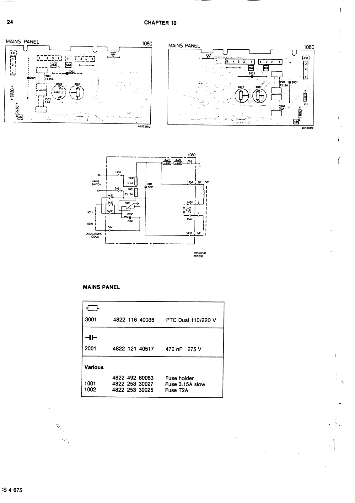
CHAPTER 10


MAINS PANEL
| ┲ | ||
|---|---|---|
| 3001 | 4822 116 40036 | PTC Duai 110/220 V |
| -11- | ||
| 2001 | 4822 121 40517 | 470 nF 275 V |
| Various | ||
|
1001
1002 |
4822 492 60063
4822 253 30027 4822 253 30025 |
Fuse holder
Fuse 3.15A slow Fuse T2A |


AUTOMATIC MULTI VOLTAGE PANEL
| 3301 | 4822 116 52133 | 30 kΩ 2.5 W |
|---|---|---|
| 3302 | 4822 116 52943 | 33 kΩ 2.5 W |
| 3305 | 4822 116 52131 | 820 kΩ 0.4 W |
| 3311 | 4822 116 52132 | 46,4 kΩ 1 W |
| 3312 | 4822 116 52132 | 46,4 kΩ 1 W |
| 3316 | 4822 116 52094 | 33 Ω 0.5 W |
| -₩- | ||
| 6301 | 4822 130 41275 | 1N5062 |
| 6302 | 4822 130 41275 | 1N5062 |
| 6303 | 4822 130 34278 | BZX79-B6V8 |
| 6304 | 4822 130 34368 | BZX79-B36 |
| 6305 | 4822 130 20181 | X0103MA thyristor |
| 6306 | 5322 130 24081 | BT151-650R thyristor |
| 6307 | 4822 130 34174 | IN5365 |
| Various | ||
| 2307 | 4822 122 40348 | 2,2nF 1 kV |
| 7301 | 4822 130 44197 | BC558B |
| 7302, 7303 | 4822 130 40937 | BC548B |
| l | ||
| l | ||
25
36 195 A12 /628
CHAPTER 11

26

1
PAL-MODULE
| Various | ||
|---|---|---|
|
1210
1233 2233 3215 3222 7292 |
4822 255 40156
4822 267 40247 4822 320 40096 4822 242 70626 4822 125 50045 4822 100 10048 4822 111 30513 4822 209 81239 |
Socket IC28 pins
Socket 5 pins Delay line chrominance X-tal 8.86 MHz Trim cap 20 pF 1 kΩ 0.1 W potm. 15 Ω 0.33 W saf. TDA3561A |
|
5210, 5219 5250 5251 5252 5292 |
4822 157 52252
4822 157 50943 4822 157 50943 4822 157 50943 4822 157 50943 |
Coil 15 µН
Coil 12 µН Coil 12 µН Coil 12 µН |
|
5292
5294 5298 |
4822 157 51056
4822 157 51756 4822 156 21026 |
Luminance delay line
Coil 10 μH Coil 34 μH |
CS 4 677
CHAPTER 11
PAL-MODULE
.
Ĵ

ADJUSTMENTS
For adjustment 1 any colour signal may be used. Adjustment 2 and 3 are effected with a colour pattern generator PM5515 or PM5519.
1. Subcarrier oscillator
Apply a colour signal and set the receiver controls to their normal settings. Interconnect points 23 and 24 of 7292.
Include a 470 Ω resistor between point 6 and point 1 of 7292.
Adjust 2233 in such a manner that the colour on the screen has practically come to a standstill. Remove the resistor and the interconnection.
2. PAL-delay line
Apply a generator signal. Set the generator to position "DEM", adjust brightness to normal and the saturation control to 3/4 of its range. Adjust 3215 so that the venetian blinds effect in the third bar disappears.
Next, adjust 5210 so that the venetian blinds effect in the first and fourth bar disappears.
Readjust 3215.
Set the generator to "Colour Bar" position and adjust 5219 so that the venetian blinds effect in the third and/or the fifth bar from the left hand side (resp. cyan and magenta) disappears.
3. The 4.43 MHz trap in the luminance circuit
Use a colour bar pattern. The receiver is normally adjusted.
Connect an oscilloscope to point 10 of 7292 and adjust 5298 to minimum amplitude of the chrominance signal present on the various brightness steps of the luminance signal.


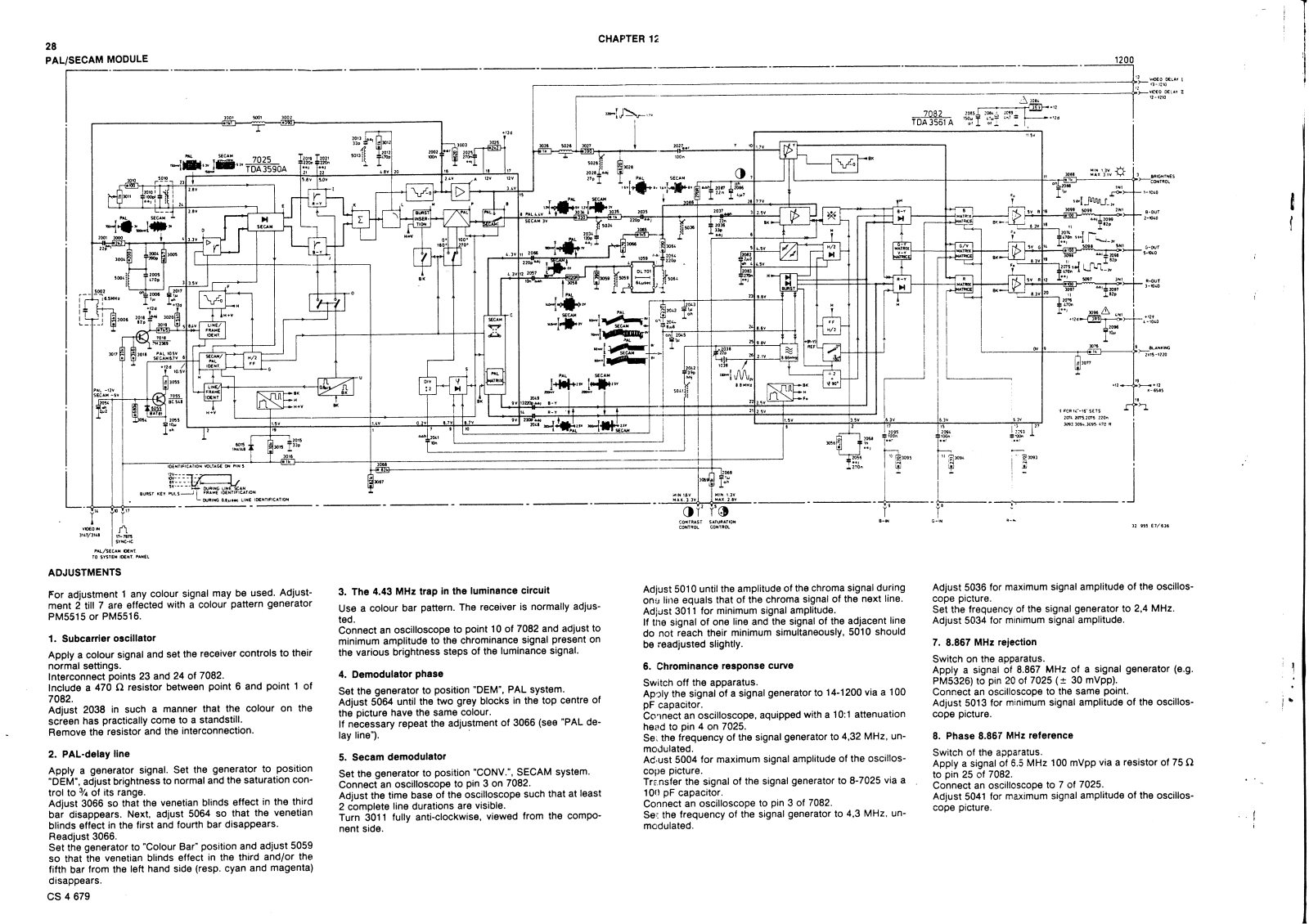
ADJUSTMENTS
For adjustment 1 any colour signal may be used. Adjustment 2 till 7 are effected with a colour pattern generator PM5515 or PM5516.
1 Subcarrier oscillator
Apply a colour signal and set the receiver controls to their normal settings.
Interconnect points 23 and 24 of 7082.
Include a 470 Ω resistor between point 6 and point 1 of 7082
Adjust 2038 in such a manner that the colour on the screen has practically come to a standstill. Remove the resistor and the interconnection.
2. PAL-delay line
Apply a generator signal. Set the generator to position "DEM", adjust brightness to normal and the saturation control to 3/4 of its range.
Adjust 3066 so that the venetian blinds effect in the third bar disappears. Next, adjust 5064 so that the venetian blinds effect in the first and fourth bar disappears. Readiust 3066.
Set the generator to "Colour Bar" position and adjust 5059 so that the venetian blinds effect in the third and/or the fifth bar from the left hand side (resp. cyan and magenta) disappears
minimum amplitude to the chrominance signal present on the various brightness steps of the luminance signal.
3. The 4.43 MHz trap in the luminance circuit
Use a colour bar pattern. The receiver is normally adjus-
Connect an oscilloscope to point 10 of 7082 and adjust to
4. Demodulator phase
ted
Set the generator to position "DEM", PAL system. Adjust 5064 until the two arey blocks in the top centre of the picture have the same colour If necessary repeat the adjustment of 3066 (see "PAL de-
lav line").
5. Secam demodulator
Set the generator to position "CONV.", SECAM system. Connect an oscilloscope to pin 3 on 7082. Adjust the time base of the oscilloscope such that at least 2 complete line durations are visible. Turn 3011 fully anti-clockwise, viewed from the component side.
Adjust 5010 until the amplitude of the chroma signal during one line equals that of the chroma signal of the next line. Adjust 3011 for minimum signal amplitude. If the signal of one line and the signal of the adjacent line do not reach their minimum simultaneously, 5010 should be readjusted slightly.
6. Chrominance response curve
Switch off the apparatus.
Apply the signal of a signal generator to 14-1200 via a 100 pF capacitor.
Connect an oscilloscope, aquipped with a 10:1 attenuation head to pin 4 on 7025.
Set the frequency of the signal generator to 4,32 MHz, unmodulated
Adjust 5004 for maximum signal amplitude of the oscilloscone picture Transfer the signal of the signal generator to 8-7025 via a
100 pF capacitor
Connect an oscilloscope to pin 3 of 7082.
Set the frequency of the signal generator to 4,3 MHz, unmodulated
Adjust 5036 for maximum signal amplitude of the oscilloscope picture. Set the frequency of the signal generator to 2,4 MHz.
Adjust 5034 for minimum signal amplitude.
7. 8.867 MHz rejection
Switch on the apparatus.
Apply a signal of 8.867 MHz of a signal generator (e.g. PM5326) to pin 20 of 7025 (± 30 mVpp). Connect an oscilloscope to the same point. Adjust 5013 for minimum signal amplitude of the oscilloscope picture.
.
8. Phase 8.867 MHz reference
Switch of the apparatus. Apply a signal of 6.5 MHz 100 mVpp via a resistor of 75 Ω to pin 25 of 7082. Connect an oscilloscope to 7 of 7025. Adjust 5041 for maximum signal amplitude of the oscilloscope picture.


 Loading...