

Page 1
Page 2

Philips Strand Lighting Offices
Philips Strand Lighting - Dallas
10911 Petal Stree t
Dallas, TX 75238
Tel: 214-647-7880
Fax: 214-647-8030
Philips Strand Lighting - Auckland
19-21 Kawana Street
Northcote, Auckland 0627
New Zealand
Tel: +64 9 481 0100
Fax: +64 9 481 0101
Philips Strand Lighting - New York
267 5th A ve, 4th Floor
New York, NY 10016
Tel: 212-213-8219
Fax: 212-532-2593
Philips Strand Lighting - Asia Limited
Room 6-10, 20/F Delta House 3 On Yiu Street
Shatin, N.T. Hong Kong
Tel: + 852 2757 3033
Fax: + 852 2757 1767
The material in this manual is for information purposes only and is subject to change without notice. Philips Strand
Lighting assumes no responsibility for any errors or omissions which may appear in this manual. For comments and
suggestions regarding corrections and/or updates to this manual, please visit the Philips Strand Lighting web site at
www.strandlighting.com or contact your nearest Philips Strand Lighting office.
El contenido de este manual es solamente para información y está sujeto a cambios sin previo aviso. Philips Strand
Lighting no asume responsabilidad por errores o omisiones que puedan aparecer. Cualquier comentario, sugerencia
o corrección con respecto a este manual, favor de dirijirlo a la oficina de Philips Strand Lighting más cercana.
Der Inhalt dieses Handbuches ist nur für Informationszwecke gedacht, Aenderungen sind vorbehalten. Philips
Strand Lighting uebernimmt keine Verantwortung für Fehler oder Irrtuemer, die in diesem Handbuch auftreten. Für
Bemerkungen und Verbesserungsvorschlaege oder Vorschlaege in Bezug auf Korrekturen und/oder
Aktualisierungen in diesem Handbuch, moechten wir Sie bitten, Kontakt mit der naechsten Philips Strand LightingNiederlassung aufzunehmen.
Le matériel décrit dans ce manuel est pour information seulement et est sujet à changements sans préavis. La
compagnie Philips Strand Lighting n'assume aucune responsibilité sur toute erreur ou ommission inscrite dans ce
manuel. Pour tous commentaires ou suggestions concernant des corrections et/ou les mises à jour de ce manuel,
veuillez s'il vous plait contacter le bureau de Philips Strand Lighting le plus proche.
Philips Strand Lighting - Europe
Marssteden 152
Enschede 7547 TD
The Netherlands
Tel: +31 53 4500424
Fax: +31 53 4500425
Website:
www.strandlighting.com
Note: Information contained in this document may not be duplicated in full or in part by any person without prior written
approval of Philips Strand Lighting. Its sole purpose is to provide the user with conceptual information on the equipment
mentioned. The use of this document for all other purposes is specifically prohibited.
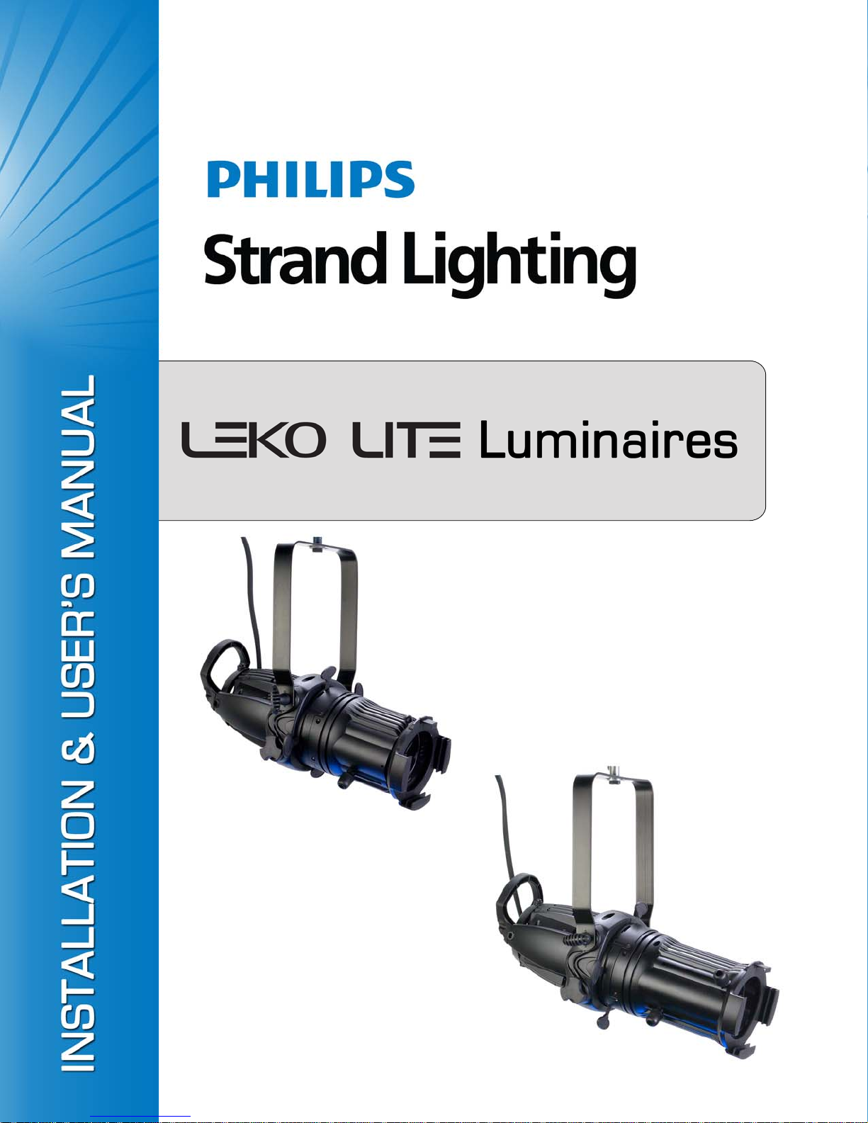
LEKO LITE Luminaire Installation & User’ s Manu al
Document Number: 02.8101.0001 B
Version as of: 25 July 201 1
©2011 Philips Group. All rights reserved.
Page 3
LEKO LITE Luminaires
IMPORTANT INFORMATION
Warnings and Notices
When using electrical equipment, basic safety precautions should always be followed including the following:
a. READ AND FOLLOW ALL SAFETY INSTRUCTIONS.
b. Do not use outdoors.
c. Do not mount near gas or electric heaters.
d. Equipment should be mounted in locations and at heights where it will not readily be subjected to
tampering by unauthorized personnel.
e. The use of accessory equipment not recommended by the manufacturer may cause an unsafe
condition.
f. Do not use this equipment for other than intended use.
g. Refer service to qualified personnel.
SAVE THESE INSTRUCTIONS.
Installation & User’s Manual
WARNING: You must have access to a main circuit breaker or other power disconnect device
before installing any wiring. Be sure that power is disconnected by removing fuses or turning the
main circuit breaker off before installation. Installing the device with power on may expose you to
dangerous voltages and damage the device. A qualified electrician must perform this instal lation.
WARNING: Refer to National Electrical Code® and local codes for cable specifications. Failure to
use proper cable can result in damage to equipment or danger to personnel.
WARNING: This equipment is intended for installation in accordance with the National Electric
Code® and local regulations. It is also intended for installation in indoor application s on ly. Before
any electrical work is performed, disconnect power at the circuit breaker or remove the fuse to avoid
shock or damage to the control. It is recommended that a qualified electrician perform this
installation.
WARNING! Remove all power from luminaire before installing lamp or performing any service. THE
LUMINAIRE PRODUCES EXTREME HEA T AND CAN BURN IF TOUCHED WITH BARE HANDS. Allow unit
to cool before servicing. Only use specified / approved lamps at the correct voltage with luminaire.
1
Page 4

Installation & User’s Manual LEKO LITE Luminaires
TABLE OF CONTENTS
Philips Strand Lighting Offices........................................................................................... Inside Front Cover
IMPORTANT INFORMATION
Warnings and Notices............................... ....................................... ................................................................ 1
TABLE OF CONTENTS
PREFACE
About this Manual .................................................................................................................................................. 3
Product Descriptions............................................................................................................................................... 3
LEKO LITE Luminaires.................................................................................................................................. 3
ACCESSORIES...................................................................................................................................................... 4
LEKO LITE Luminaire Lamps....................................................................................................................... 4
LEKO LITE Luminaire Connectors................................................................................................................ 4
LEKO LITE Luminaire Clamps & Safety Cable............................................................................................ 4
LEKO LITE Luminaire Frames / Gobo Holders / Iris.................................................................................... 4
LEKO LITE LUMINAIRE OVERVIEW
Variable Beam Models............................................................................................................................................ 5
Fixed Beam Models................................................................................................................................................ 5
Standards and Conformance............................................. ...................................................................................... 6
Compliance...................................................................................................................................................... 6
INSTALLATION AND SET UP
Power Requirements............................................................................................................................................... 7
Lamp Installation.................................................................................................................................................... 7
Connecting Power................................................................................................................................................... 8
Mounting ................................................................................................................................................................ 8
Using Supplied C-Clamp................................................................................................................................. 8
Safety Cable..................................................................................................................................................... 8
Pan and Tilt Adjustments........................................................................................................................................ 9
Pan Adjustment ................................................ ........................................ ....................................................... 9
Tilt Adjustment...................................................................................... .......................................................... 9
FOCUS AND BEAM ADJUSTMENTS
Variable Beam Angle Models............................................................................................................................... 10
Light Field Optimization............................................................ ................................................................... 10
Beam Angle and Focus Adjustments ............................................................................................................ 10
Fixed Beam Angle Models................................................................................................................................... 11
Light Field Optimization............................................................ ................................................................... 11
Beam Angle and Focus Adjustments ............................................................................................................ 11
Beam Shutter Operation ............................................................................................................................ ........... 12
Gobos.................................................................................................................................................................... 12
MAINTENANCE AND CARE
Before Cleaning................................................................................................................... ................................. 13
Cleaning.......................................................................................................................................... ...................... 13
FEATURES AND SPECIFICATIONS
Standard Features.................................................................................................................................................. 14
Standard Specifications ..................................................................................................................... ................... 14
2 TABLE OF CONTENTS
Page 5
LEKO LITE Luminaires
PREFACE
1. About this Manual
The document provides installation and operation instructions for the following products:
• LEKO LITE Luminaires (refer to "Product Descriptions" for indi vidual product models).
Please read all instructions before installing or using this product. Retain this manual for future reference.
Additional product information and descriptions may be downloaded at www.strandlighting.com.
2. Product Descriptions
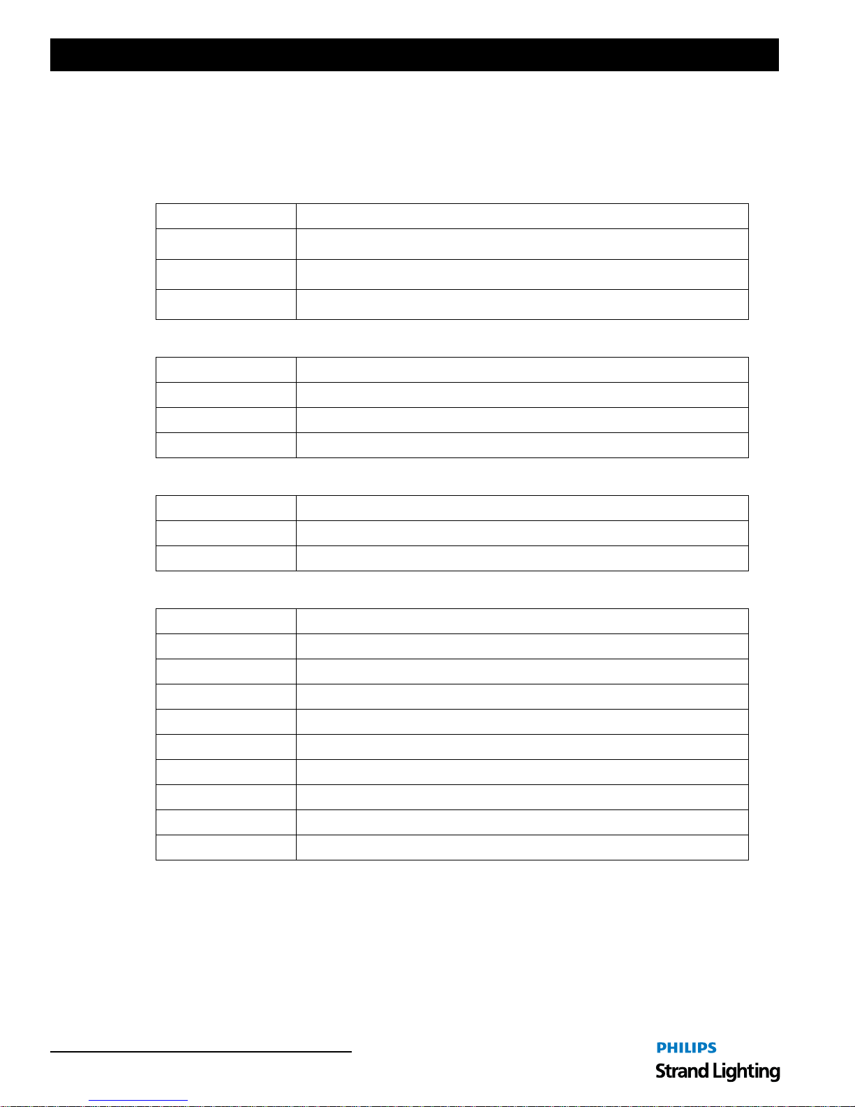
This manual covers the following LEKO LITE Luminaire models:
LEKO LITE Luminaires
Installation & User’s Manual
11500C - 5
o
Fixed Beam Angle
LEKO LITE Luminaire
Part Number Description
11430C
11440C
11500C
11510C
11520C
11530C
11540C
11550C
o
15
to 32o Variable Beam Angle LEKO LITE Luminaire
o
23
to 50o Variable Beam Angle LEKO LITE Luminaire
o
5
Fixed Beam Angle LEKO LITE Luminaire
o
10
Fixed Beam Angle LEKO LITE Luminaire
o
19
Fixed Beam Angle LEKO LITE Luminaire
o
26
Fixed Beam Angle LEKO LITE Luminaire
o
36
Fixed Beam Angle LEKO LITE Luminaire
o
50
Fixed Beam Angle LEKO LITE Luminaire
11440C - 23o to 50o Variable Beam Angle
LEKO LITE Luminaire
Notes:
(1) All LEKO LITE Luminaires are All LEKO LITE luminaires are supplied with 360° rotation mounting yoke,
color frame, C-Clamp (SC), and AC power cable.
(2) Product accessories can be found in
"ACCESSORIES" on page 4.
About this Manual 3
Page 6
Installation & User’s Manual LEKO LITE Luminaires
3. ACCESSORIES
Contact your Authorized Philips Strand Lighting Dealer for price and availability of all accessories for LEK O LITE
Luminaires. Additional information can be found on the Philips Strand Lighting web site at www.strandlighting.com.
LEKO LITE Luminaire Lamps
Part Number Description
NPA Hi-Brite Lamp, 575W, 115V Long Life Lamp
GRS Hi-Brite Lamp, 750W , 115V Fast Fit
NPC Hi-Brite Lamp, 800W, 240V Fast Fit
LEKO LITE Luminaire Connectors
Part Number Description
GR 15A, NEMA 5-15P Male Edison Connector
GP 20A, Male Stage Pin Connector
GTL 20A, NEMA L5-20P Male Twist-Lock Connector
LEKO LITE Luminaire Clamps & Safety Cable
Part Number Description
SC C-Clamp for 3/4-inch to 1-1/2-inch Pipe
82003 Safety Cable
LEKO LITE Luminaire Frames / Gobo Holders / Iris
Part Number Description
18045 B-Size Gobo Holder
18049 Iris, 24 Leaf
18114 Color Frame
18115 High Hat
18136 5-Degree Color Frame
18137 10-Degree Color Frame
18139 10-Degree High Hat
18143 Donut
18147 5-inch Gel Frame Extender
4 PREFACE
Page 7
LEKO LITE Luminaires
LEKO LITE LUMINAIRE OVERVIEW
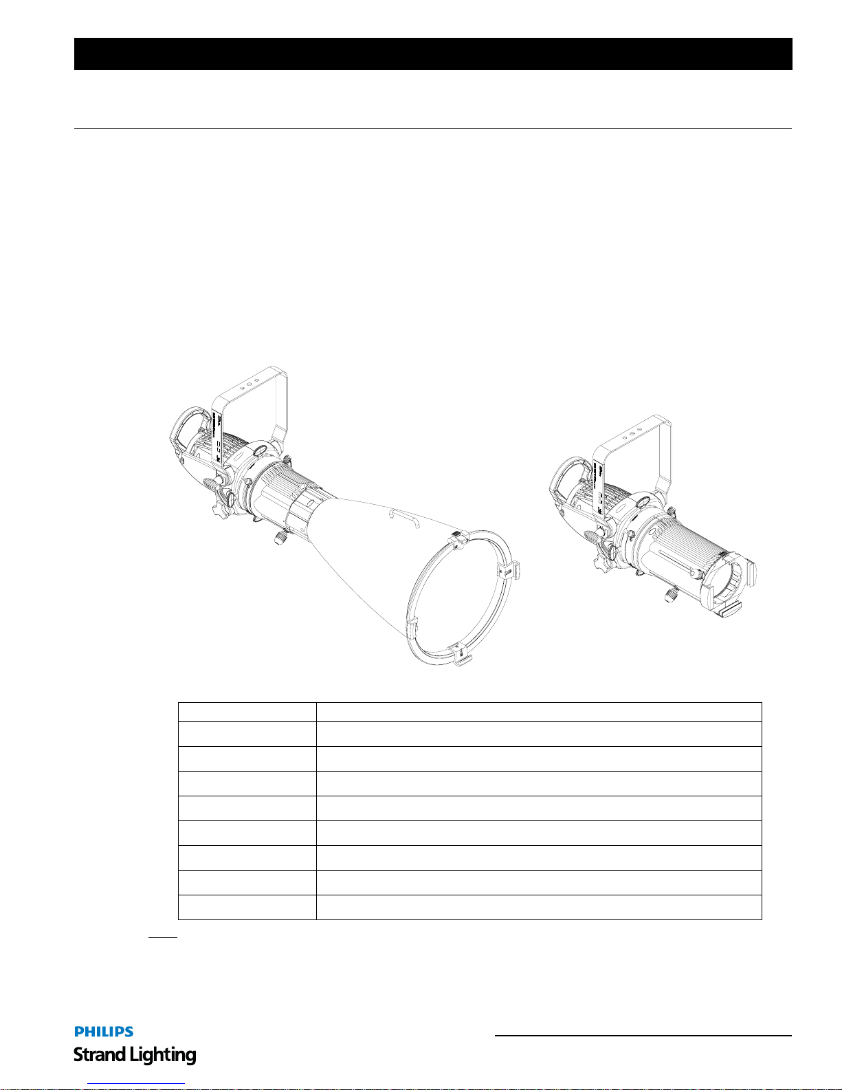
1. Variable Beam Models
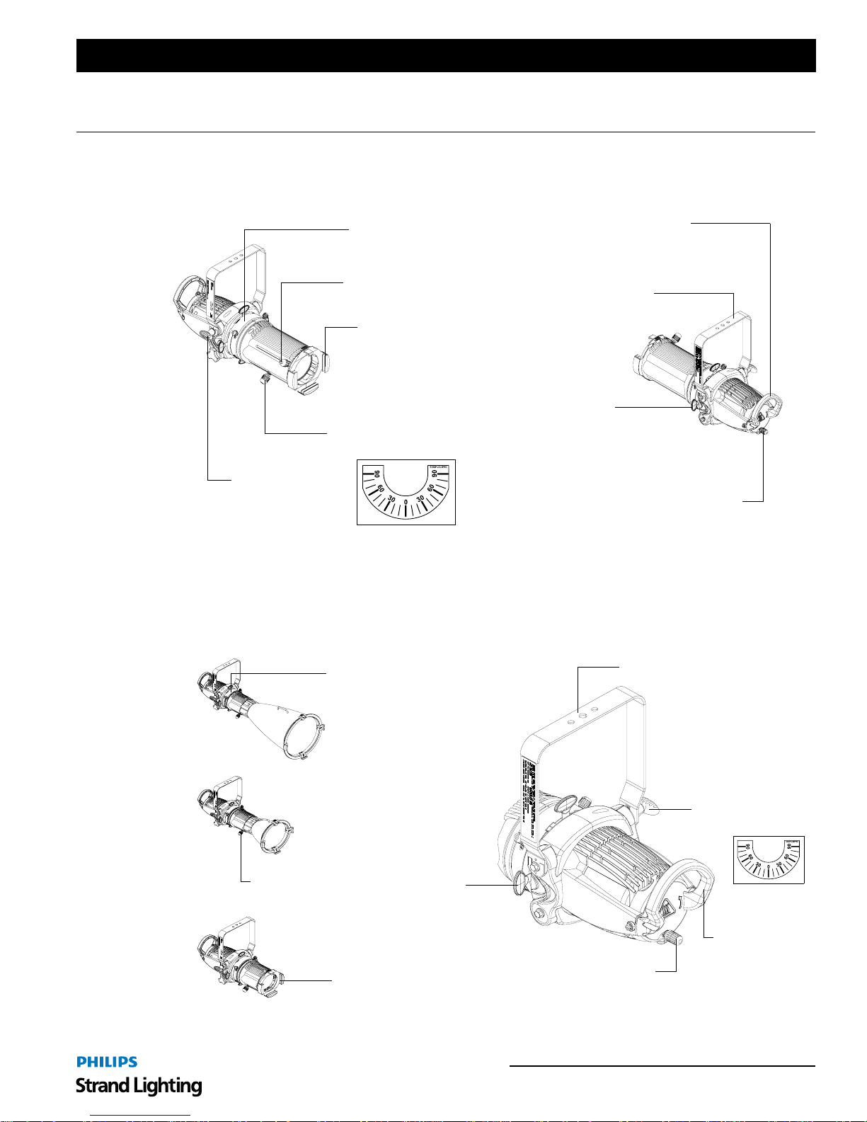
Figure 1 illustrates the common features of all variable beam model LEKO LITE Luminaires.
Installation & User’s Manual
Luminaire Handle
Yoke Assembly
(4 each)
T-Handle Tilt Lock /
Tilt Angle Indicator
Gobo Access Panel
(T wo slot s for gobo / iris)
Beam Angle
Adjustment Knob
Two Position
Frame Holder
Beam Shutters
Focus Adjustment Knob
Beam Distribution Adjustment Knob
(for multi-faceted, dichroic glass reflector)
Figure 1: Variable Beam Model Features
2. Fixed Beam Models
Figure 2 illustrates the common features of all fixed beam model LEKO LITE Luminaires. Note, common features
shown on different models for variety. Check product specification sheet for specific model field angles and
information.
Gobo Access Panel
(Two slots for gobo / iris)
Focus
Adjustment Knob
Frame Holder
Yoke Assembly
T-Handle Tilt Lock /
Tilt Angle Indicator
Beam Shutters
(4 each)
Luminaire
Handle
Beam Distribution Adjustment Knob
(for multi-faceted, dichroic glass reflector)
Figure 2: Fixed Beam Model Features
Variable Beam Models 5
Page 8
Installation & User’s Manual LEKO LITE Luminaires
3. Standards and Conformance
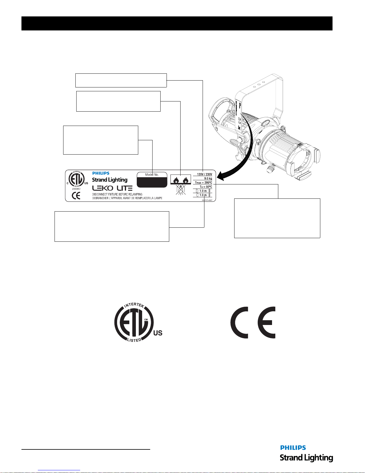
LEKO LITE Luminaires are designed to conform to the latest safety standards and requirements. The following
describes the safety and operational information on the luminaire’s label.
Luminaire operational voltage range.
Do not mount luminaire on, or allow
contact with, flammable materials.
Luminaire model number. For
any warranty service, you must
provide this number and date of
purchase.
Tmax specifies the maximum surface
temperature for the luminaire body.
Specifies the minimum distance from the luminaire
to a flammable surface. The top figure is to a
surface in the light beam and the bottom figure to a
surface near the luminaire body.
Figure 1: Luminaire Warning Label
Ta specifies the maximum ambient
operating temperature for the
luminaire.
Compliance
All LEKO LITE Luminaires are ETL-listed and conform to all applicable CE requirements. You should adhere to all
local and national safety requirements and codes when mounting and using the LEKO LITE Luminaire.
C
6 LEKO LITE LUMINAIRE OVERVIEW
Page 9
LEKO LITE Luminaires
INSTALLATION AND SET UP
1. Power Requirements
LEKO LITE Luminaires are designed to operate at either 115 volts AC or 240 volts AC only. If the luminaire was
purchased without a factory-installed connector, see "Connecting Power" on page 8 as a guide for connector
installation.
WARNING! Luminaire lamp must match the connected input voltage (see "LEKO LITE Luminaire Lamps" on page
4 for available lamp types).
2. Lamp Installation
Lamping and relamping is quick and easy. All lamping should be done with the power removed from the luminaire.
Great care should be used when handling the lamp.
WARNING! Remove all power from luminaire before installing lamp or performing any service. Allow unit to cool
before servicing. Only use specified / approved lamps at the correct voltage with luminaire.
CAUTION: Wear cotton gloves or other covering while handling and installing lamp. Touching lamp glass with
bare fingers will leave oil and may cause the lamp to explode or reduce lamp life. Clean lamp with isopropyl alcohol
if any finger prints or oils are on the lamp.
Installation & User’s Manual
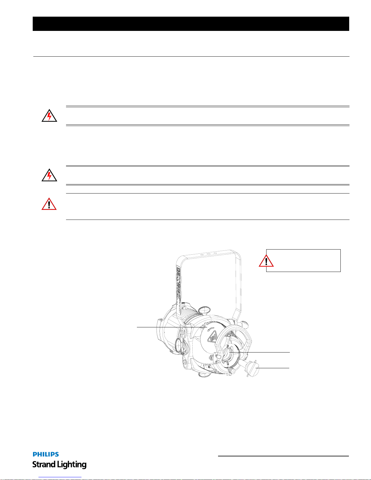
To install a lamp into luminaire:
Step 1. At rear of luminaire, swing open lamp access panel.
Remove power and allow
luminaire to cool before
handling or servicing.
Lamp Access Panel
Lamp Socket
Lamp
Figure 3: Installing a Lamp
Step 2. Align lamp pins with lamp holder.
Step 3. Slide lamp into lamp holder.
Step 4. Lock lamp into position by gently turning lamp clockwise in lamp holder until is snaps into place.
Step 5. Close lamp access panel.
Step 6. Connect power, adjust beam distribution and focus as desired. See "FOCUS AND BEAM
ADJUSTMENTS" on page 10 for more information.
Power Requirements 7
Page 10
Installation & User’s Manual LEKO LITE Luminaires
3. Connecting Power
The unit is supplied with a 39-inch (1 meter) AC input cable. If a factory connector was not ordered, Table 1
describes how to connect power to your LEKO LITE Luminaire . Field wiring of the LEKO LITE Luminaire is
straight forward. The following wiring scheme is required:
Table 1: LEKO LITE Luminaire AC Input Wiring
Wire Color Purpose
Black Main / Line (120 to 240VAC)
White Neutral
Green/Yellow Ground
WARNING! Risk of Fire or Injury! LEKO LITE Luminaires must be grounded per local and/or national codes. Any
installed connector must have the required cord grip and be rated at or above the voltage and wattage or voltampere
values marked on the luminaire.
4. Mounting
WARNING! Before attempting any installation or service, disconnect all power at power source. Dimming the
luminaire does not disconnect power. Installation and service should only be performed by a trained and qualified
professional.
Using Supplied C-Clamp
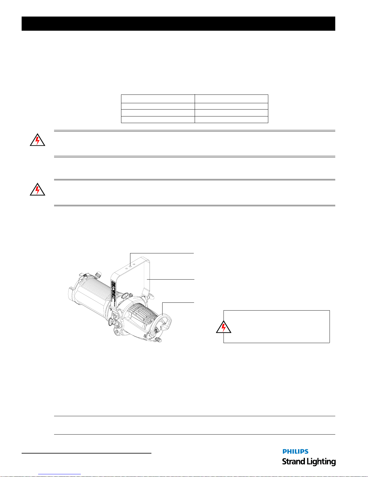
As illustrated in Figure 4, at yoke assembly, thread clamp mounting bolt (with washer installed) through center clamp
mounting hole at top of yoke, install another washer, then thread bolt into clamp. Securely tighten bolt into clamp (but
do not overtighten).
Center Clamp Mounting Hole
Yoke Assembly
Luminaire Handle
NOTE: To avoid premature lamp failure it is
essential that the luminaire is always mounted so
the yoke is horizontal and with the lamp base down
with the lamp adjustment knob is at the bottom of
the rear lamp plate (as shown).
Figure 4: Luminaire Mounting
To mount on a telescopic stand, reverse the yoke under the luminaire and bolt to stand. Please note luminaire
orientation (see note in Figure 4).
Safety Cable
A safety cable* MUST always be used when rigging luminaires on bars, truss, etc. A safety cable should be routed
through both the luminaire handle and yoke assembly. You should always consult and follow all local and national
codes and regulations for mounting and installation of luminaire.
Note: *Safety cables are sold separately and available from Philips Strand Lighting. Refer to "LEKO LITE
Luminaire Clamps & Safety Cable" on page 4 for part numbers.
8 INSTALLATION AND SET UP
Page 11
LEKO LITE Luminaires
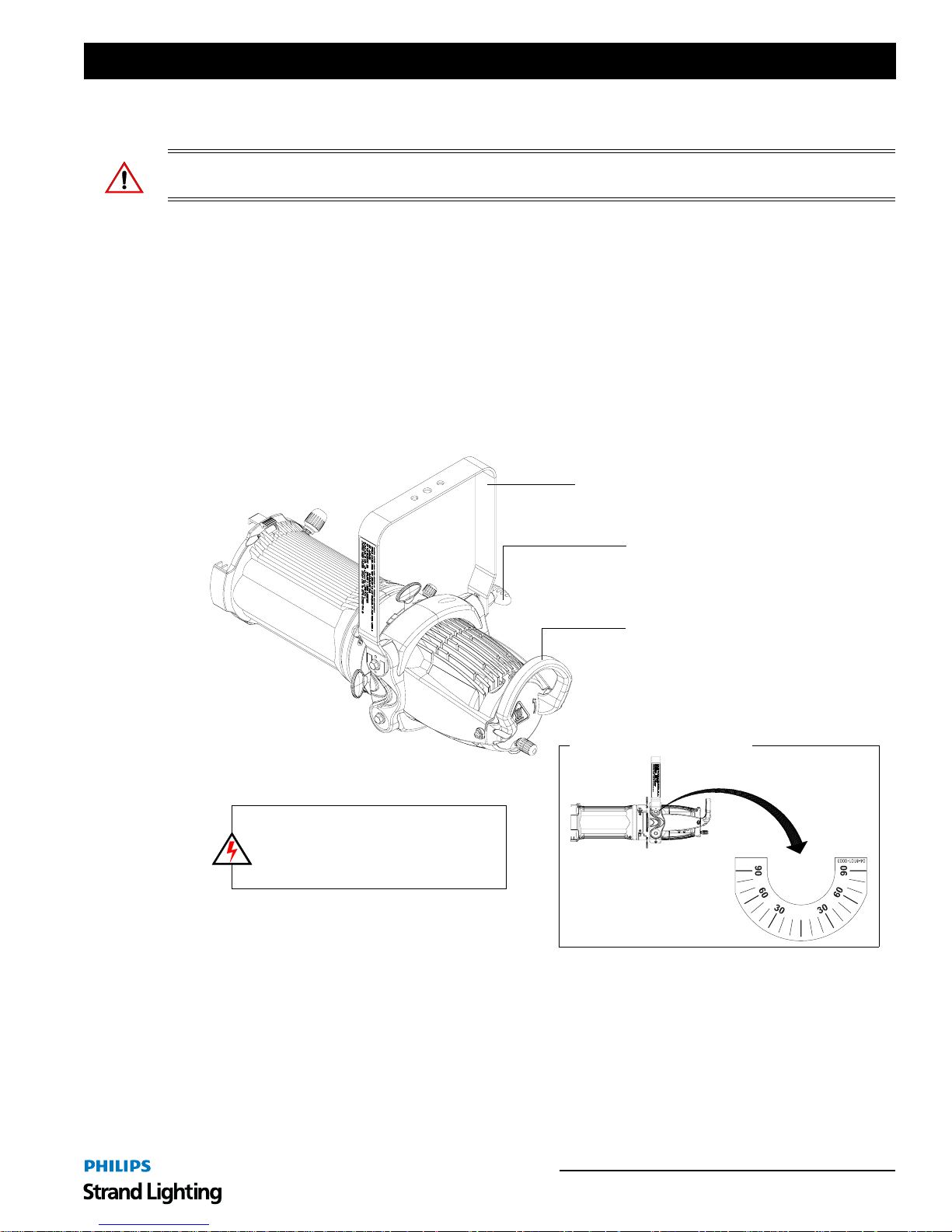
5. Pan and Tilt Adjustments
WARNING! When adjusting the luminaire’s position, it is important to wear protective gloves. The luminaire
produces extreme heat and all surfaces could cause serious burns if touched.
Pan Adjustment
The pan adjustment of a LEKO LITE luminaire is achieved by loosening the yoke bolt or yoke bolt set screw of the
securing clamp attached to the luminaire's yoke assembly. Loosen the bolt or set screw, set the luminaire to the
desired position and retighten.
Tilt Adjustment
LEKO LITE Luminaires offer variable tilt settings. The unit can be set at a specific angle (in relation to its mounting
position) or at an angle between 0 to 90 degrees. When the yoke is in the position shown in Figure 5, you have full
range access to shutters the gate etc. If you flip the yoke over some access is reduced but the over all volume the
luminaire takes up is reduced. This is particularly useful in tightly hung lighting po sitions or in theatres with low
grids.
Installation & User’s Manual
Yoke Assembly
NOTE: To avoid premature lamp failure it is
essential that the luminaire is always mounted so
the yoke is horizontal and with the lamp base down
with the lamp adjustment knob is at the bottom of
the rear lamp plate (as shown).
Figure 5: Luminaire Tilt Adjustment
T-Handle T ilt Lock
Luminaire Handle
Luminaire Tilt Label Detail
To adjust and set tilt angle of the luminaire:
Step 1. Mount luminaire in desired location (see "Mounting" on page 8 for more information).
Step 2. Loosen, but do not remove, T-Handle Tilt Locks at base of yoke assembly as shown in Figure 5.
Step 3. Position luminaire to desired position.
Step 4. Retighten T-Handle Tilt Locks to set position.
Pan and Tilt Adjustments 9
Page 12
Installation & User’s Manual LEKO LITE Luminaires
FOCUS AND BEAM ADJUSTMENTS
1. Variable Beam Angle Models
CAUTION: When adjusting the luminaire’s focus or beam distribution, it is important to wear protective gloves.
The luminaire produces extreme heat and all surfaces could cause serious burns if touched.
Light Field Optimization
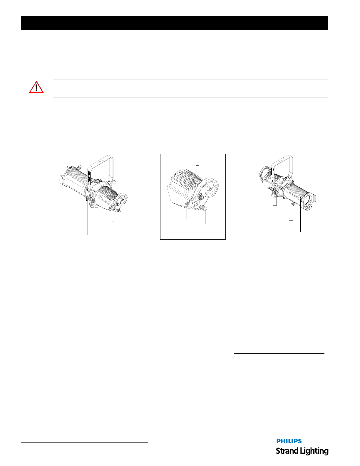
Before adjusting beam focus, the luminaire’s light field should be adjusted for optimum performance (Peak Field or
Flat Field). The Beam Distribution Adjustment Knob moves the lamp in and out of the reflector until light
distribution is set as desired. The X and Y-Axis adjustments provide left/right and up/down adjustments to the
reflector in relation to the lamp.
Detail A
Y-Axis
Beam Focus Adjustment Beam Distribution Adjustment
Beam Shutters
(4 Each)
See Detail A
Beam Shutters (4 Each)
X-Axis
Beam Distribution
Adjustment Knob
Focus Adjustment Knob
Beam Angle
Adjustment Knob
Figure 6: Variable Beam Models - Beam Adjustments
To optimize luminaire light field (beam distribution):
Step 1. Make sure all frame shutters are open (out of beam path).
Step 2. Using X-Axis Adjustment, Y-Axis Adjustment, and Beam Distribution Adjustment Knob (as indicated in
Figure 6) set beam distribution as desired. Note, X and Y-Axis adjustments require the use of a flat-head
screwdriver.
Beam Angle and Focus Adjustments
Variable Beam Angle models have both angle and focus adjustments.
To adjust beam angle and focus:
Step 1. Optimize light field before adjusting beam angle and focus. See procedure in "Light Field Optimization" in
previous section.
Step 2. Make sure all frame shutters are open (out of beam path).
Step 3. Loosen Beam Angle Adjustment Knob as shown in Figure 6.
Step 4. Move along forward (or back) until beam angle is set as desired
Step 5. Hand-tighten Beam Angle Adjustment Knob to lock position.
Step 6. Loosen Focus Adjustment Knob.
Step 7. Move along forward (or back) until beam focus is set as desired
Step 8. Hand-tighten Focus Adjustment Knob to lock position.
Note: When using high-output, high
performance lamps, it is possible that
a combination of focus, beam angle
and color gel type may result in
reduced gel life. It is advised to use
the 5-inch Gel Frame Extender part
number 18147 (sold separately - see
"LEKO LITE Luminaire Frames /
Gobo Holders / Iris" on page 4).
10 FOCUS AND BEAM ADJUSTMENTS
Page 13
LEKO LITE Luminaires
2. Fixed Beam Angle Models
CAUTION: When adjusting the luminaire’s focus or beam distribution, it is important to wear protective gloves.
The luminaire produces extreme heat and all surfaces could cause serious burns if touched.
Light Field Optimization
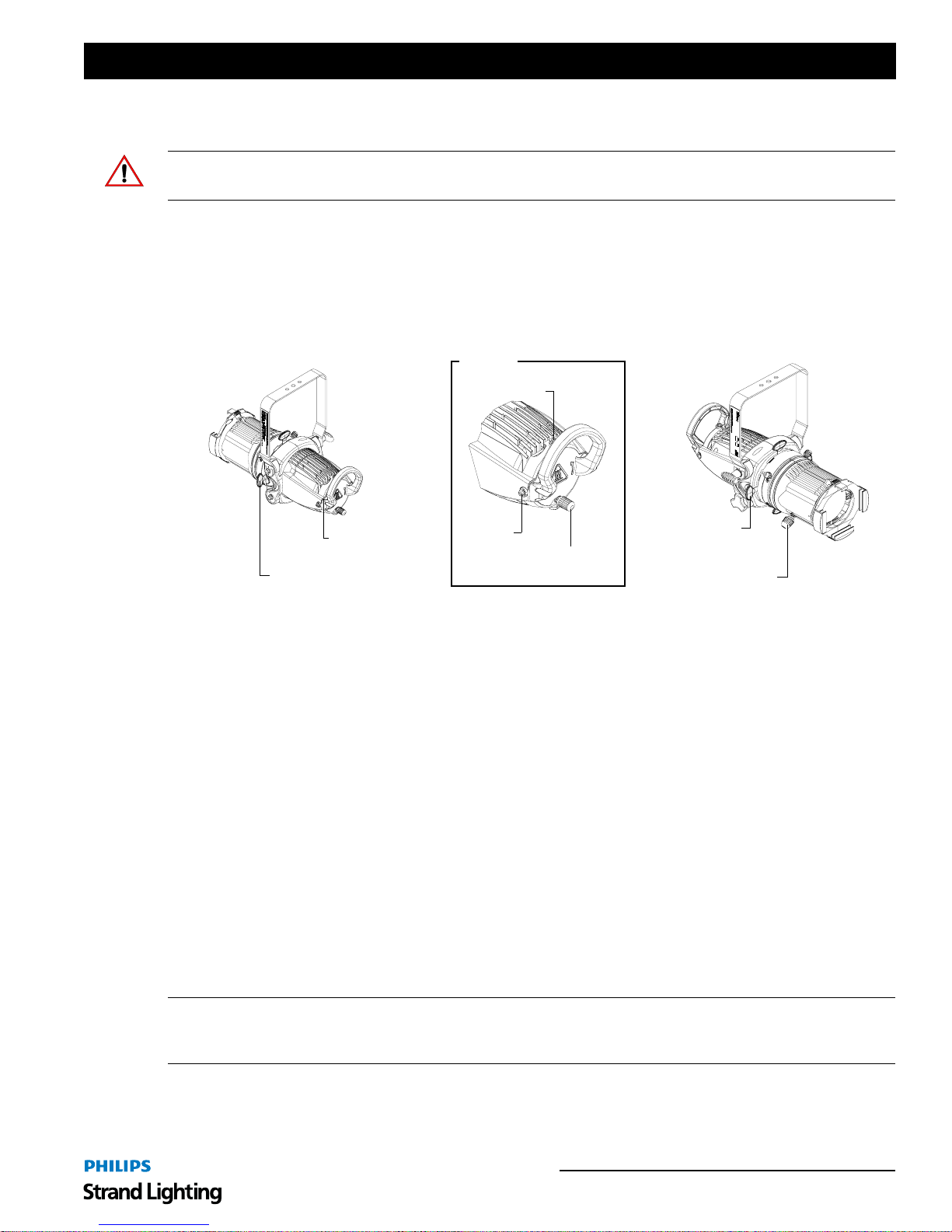
Before adjusting beam focus, the luminaire’s light field should be adjusted for optimum performance (Peak Field or
Flat Field). The Beam Distribution Adjustment Knob moves the lamp in and out of the reflector until light
distribution is set as desired. The X and Y-Axis adjustments provide left/right and up/down adjustments to the
reflector in relation to the lamp.
Installation & User’s Manual
Beam Focus Adjustment Beam Distribution Adjustment
Beam Shutters
(4 Each)
Focus Adjustment Knob
See Detail A
Beam Shutters (4 Each)
Detail A
Y-Axis
X-Axis
Beam Distribution
Adjustment Knob
Figure 7: Fixed Beam Models - Beam Adjustments
To optimize luminaire light field (beam distribution):
Step 1. Make sure all frame shutters are open (out of beam path).
Step 2. Using X-Axis Adjustment, Y-Axis Adjustment, and Beam Distribution Adjustment Knob (as indicated in
Figure 7) set beam distribution as desired. Note, X and Y-Axis adjustments require the use of a flat-head
screwdriver.
Beam Angle and Focus Adjustments
Fixed Beam Angle models have hard/soft focus adjustments.
To adjust beam angle and focus:
Step 1. Optimize light field before adjusting beam angle and focus. See procedure in "Light Field Optimization" in
previous section.
Step 2. Make sure all frame shutters are open (out of beam path).
Step 3. Loosen Focus Adjustment Knob as shown in Figure 7.
Step 4. Move along forward (or back) until beam focus is set as desired
Step 5. Hand-tighten Focus Adjustment Knob to lock position.
Note: When using high-output, high performance lamps, it is possible that a combination of focus, beam angle and
color gel type may result in reduced gel life. It is advised to use the 5-inch Gel Frame Extender part number 18147
(sold separately - see "LEKO LITE Luminaire Frames / Gobo Holders / Iris" on page 4).
Fixed Beam Angle Models 11
Page 14
Installation & User’s Manual LEKO LITE Luminaires
3. Beam Shutter Operation
CAUTION: When adjusting the luminaire’s beam shutter, it is important to wear protective gloves. The luminaire
produces extreme heat and all surfaces could cause serious burns if touched.
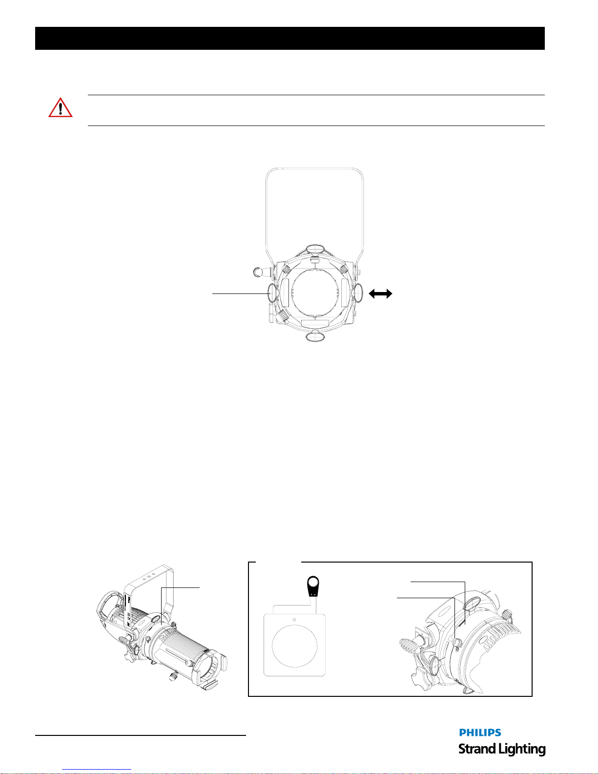
Each LEKO LITE Luminaire is equipped with four independent shutters (as shown in Fig ure 8) to block or shape
light as desired. After the luminaire is installed and positioned, move the shutters in or out as required.
Beam Shutters
(4 Each)
Front View
Move beam shutters
in and out as desired.
Figure 8: LEKO LITE Luminaire Beam Shutters
4. Gobos
Each LEKO LITE Luminaire is capable of holding two gobo holders, each containing one "B" sized glass or steel
gobo. Note, each LEKO LITE Luminaire is supplied with one gobo holder. additional holders can be purchased from
your local Philips Strand Lighting Authorized Dealer. For more information, refer to "LEKO LITE Luminaire Frames
/ Gobo Holders / Iris" on page 4.
To install or change a gobo:
Step 1. As shown in Figure 9, loosen, but do not remove, two retaining knobs that secure gobo access panel. Slide
open gobo access panel.
Step 2. Install gobo into gobo holder in desired orientation.
Step 3. Slide gobo holder into luminaire gobo slot.
Step 4. Close gobo access door. Make sure gobo holder handle fits inside one of two slots in gobo access panel.
Step 5. Hand tighten gobo access panel retaining knobs.
Detail A
See Detail
A
Figure 9: LEKO LITE Luminaire Gobo Holder and Gobo Installation
12 FOCUS AND BEAM ADJUSTMENTS
Gobo Access Panel
Retaining Knobs
(2 Each)
Gobo
Area
Gobo Holder
Page 15
LEKO LITE Luminaires
MAINTENANCE AND CARE
1. Before Cleaning
• All cleaning should be performed with power completely removed from the luminaire.
• Never remove protective covers when lum inaire is powered.
• Wear appropriate protective eye wear and gloves when cleaning the fixture.
All service and maintenance, other than described herein, should be performed by a qualified technician or
Authorized Service Center.
WARNING! THE LUMINAIRE PRODUCES EXTREME HEAT AND CAN BURN IF TOUCHED WITH BARE
HANDS. Allow unit to cool before servicing.
2. Cleaning
Additional care needs to be taken with the protective coating on the luminaire’s reflector.
The following is a list of cleaning materials required to care for your LEKO LITE Luminaire:
• Lint free lens tissue
• Lint or powder free gloves
• Reagent grade isopropyl alcohol*
Installation & User’s Manual
• A mild soap solution.
Note: *Reagent grade isopropyl alcohol is good to use on the luminaire’s optics with anti-reflection coatings.
If the lens is still dirty after using isopropyl alcohol, for instance if fingerprints or oil is just redistributed and not
cleaned off the optic, then a mild soap and water solution can be used to gently wash the lens. Repeat the cleani ng
with isopropyl alcohol to eliminate streaks and soap residue.
WARNING! Under no circumstances should ammonia-based cleaners, acetone, or other harsh solvents be used on or
near the LEKO LITE Luminaire. These types of cleaners or solvents can permanently damage the optics or housings
of the fixture.
If you have any questions regarding the use or care of your LEKO LITE Luminaire, please contact Philips Strand
Lighting technical support or your local Authorized Dealer.
Before Cleaning 13
Page 16
Installation & User’s Manual LEKO LITE Luminaires
FEATURES AND SPECIFICATIONS
1. Standard Features
LEKO LITE luminaires offer excellent light output, superb distribution and the smoothest soft edge while
maintaining beam size for sharp gobo, edge and shutter focus.
The LEKO LITE luminaire contains the following standard features:
• Precision optical system with high-light output.
• Multi-faceted dichroic glass reflector for maximum output performance.
• Cool-beam operatio n for extended gobo, shutter, and gel life.
• X, Y, and Z axis beam peak/flat field adjustment for optimum performance.
• Fixed beam models available in 5, 10, 19, 26, 36, and 50-degree beam angles.
• Variable beam models available in 15 to 32-degree and 23 to 50-degree.
• Easy lamp change, using Ph ilips FastFit technology, with out the use of tools.
• Lamp options - 575W, 750W (115V) or 800W (240V) Philips Hi-Brite, FastFit lamps.
• Wide gate will fit 2 gobo holders, including glass gobo holder, drop-in iris or rotating gobo holder.
• Three plane, four indepen dent beam shutters for triangular shutter cuts.
• Smooth 360-degree body rotation for quick and easy gobo and shutter positioning.
• 120V or 240V operatio n.
• ETL/cETL Listed and CE Marked.
2. Standard Specifications
Source*: Hi-Brite, FastFit 575W 115V Long Life Lamp
Hi-Brite, FastFit 750W 115V Lamp
Hi-Brite, FastFit 800W 240V Lamp
Input Voltage: 120V or 240V (depending on lamp used)
Frequency: 50/60Hz
Ratings: Up to 800W (max.)
Ambient Temperature: 0 to 45 degrees C (32 to 113 degrees F)
Humidity: 5%-95% Non condensing
Cooling: Natural Convection
Construction: Die cast aluminum housing with black epoxy powder coat. Stainless steel shutters.
Gate: Plated steel
Gobo Size: B Size
Color Frame Sizes: 6-1/4" x 6-1/4" (models: 11430C, 11440C, 11520C, 11530C, 11540C, 11550C)
12" x 12" (models: 11500C)
16" x 16" (models: 11510C)
Shutters: Included, four independent shutters on three planes
Lenses: Crown glass coated aspheric lens
Reflector: Multi-faceted, dichroic glass reflector
Weight: 11430C: 20.4 lbs / 9.3 kg
11440C: 20.2 lbs / 9.2 kg
11500C: 23.5 lbs / 10.7 kg
11510C: 19.7 lbs / 8.9 kg
11520C: 18.9 lbs / 8.6 kg
11530C: 18.9 lbs / 8.6 kg
11540C: 18.9 lbs / 8.6 kg
11550C: 18.9 lbs / 8.6 kg
Compliance: ETL / cETL Listed (North America models) and CE Marked (International models)
*As ordered by customer with luminaire.
Note: Common model specifications shown. For specific model specifications, features, and accessories, refer to the
product specification sheet or visit the Philips Strand Lighting web site at www.strandlighting.com for more details.
14 FEATURES AND SPECIFICATIONS
Page 17
LEKO LITE Luminaires
Notes
Installation & User’s Manual
Standard Specifications 15
Page 18
 Loading...