

Philips 109B6 Schematic
Service
Service
Service
V40 109B6
Model: 109B60/00
SAFETY NOTICE
ANY PERSON ATTEMPTING TO SERVICE THIS CHASSIS MUST FAMILIARIZE HIMSELF WITH THE CHASSIS
AND BE AWARE OF THE NECESSARY SAFETY PRECAUTIONS TO BE USED WHEN SERVICING ELECTRONIC
EQUIPMENT CONTAINING HIGH VOLTAGES.
CAUTION: USE A SEPARATE ISOLATION TRANSFORMER FOR THIS UNIT WHEN SERVICING.
REFER TO BACK COVER FOR IMPORTANT SAFETY GUIDELINES
Published by BCU Monitors Printed in Suzhou Copyright reserved Subject to modification F Sep. 24 2004
GB
3138 106 10426
2
109B6 CRT
Go to cover page
Important Safety Notice
Proper service and repair is important to the safe, reliable
operation of all Philips Consumer Electronics Company**
Equipment. The service procedures recommended by
Philips and described in this service manual are effective
methods of performing service operations. Some of these
service operations require the use of tools specially designed
for the purpose. The special tools should be used when and
as recommended.
It is important to note that this manual contains various
CAUTIONSandNOTICESwhichshouldbecarefullyreadin
order to minimize the risk of personal injury to service
personnel. The possibility exists that improper service
methods may damage the equipment. It is also important to
understand that these CAUTIONS and NOTICES ARE NOT
EXHAUSTIVE. Philips could not possibly know, evaluate and
advise the service trade of all conceivable ways in which
service might be done or of the possible hazardous
consequences of each way. Consequently, Philips has not
undertaken any such broad evaluation. Accordingly, a
servicer who uses a service procedure or tool which is not
recommended by Philips must first satisfy himself thoroughly
that neither his safety nor the safe operation of the
equipment will be jeopardized by the service method
selected.
FORPRODUCTSCONTAININGLASER:
DANGER-
CAUTION-
CAUTION-
TO ENSURE THE CONTINUED RELIABILITY OF THIS
PRODUCT, USE ONLY ORIGINAL MANUFACTURER'S REPLACEMENT
PARTS, WHICH ARE LISTED WITH THEIR
PARTNUMBERSINTHEPARTSLISTSECTIONOFTHISSERVICE
MANUAL.
Invisible laser radiation when open.
AVOIDDIRECTEXPOSURETOBEAM.
Use of controls or adjustments or
performance of procedures other than
those specified herein may result in
hazardous radiation exposure.
The use of optical instruments with this
product will increase eye hazard.
* *Hereafter throughout this manual, Philips Consumer
Electronics Company will be referred to as Philips.
WARNING
Critical components having special safety characteristics are
identified with a by the Ref. No. in the parts list and
enclosed within a broken line* (where several critical
components are grouped in one area) along with the safety
symbol on the schematics or exploded views.
!
Use of substitute replacement parts which do not have the
same specified safety characteristics may create shock, fire,
or other hazards.
Under no circumstances should the original design be
modified or altered without written permission from Philips.
Philips assumes no liability, express or implied, arising out of
any unauthorized modification of design.
Servicer assumes all liability.
!
* Broken Line
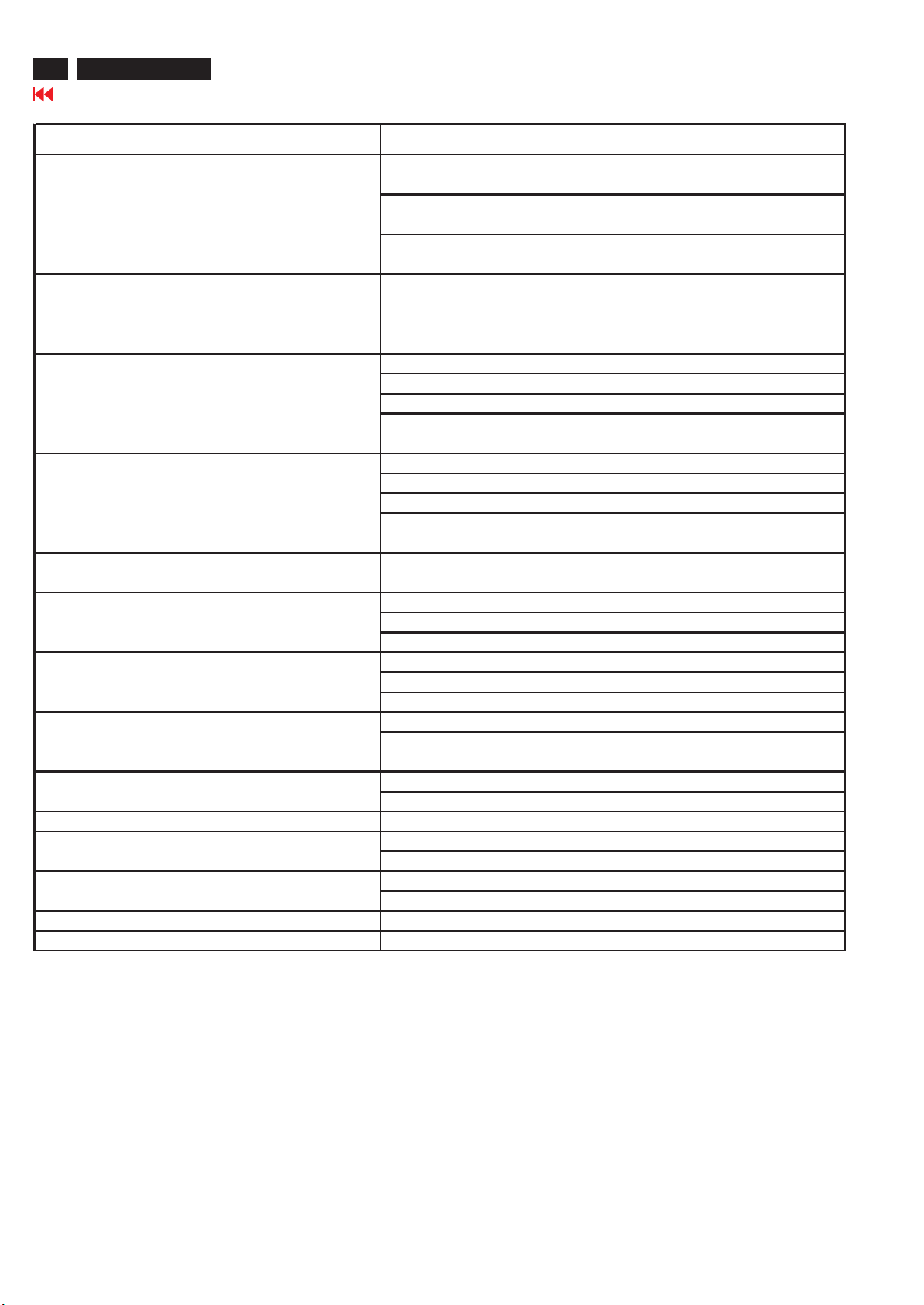
Technical Data
109B6 CRT
Go to cover page
3
I. Basic Data
1. Description :Auto-Scan Ultra HighResolutionDigital Color Monitor
2. Commercial Release :Sep, 20,2004
3. CRT:
Screen size : 19"Flat SquareConventiontube
Diagonal VIS : 18”
Shadow Mask : Invar
Dot Pitch : 0.26mm for SDI, LG & CPTCRT
Horizontal pitch : 0.21mm for SDI, LG & CPTCRT
Deflectionangle : 90 degr
Aspect ratio:4:3
Source :LG/SDI/CPT
Surface :Anti-reflection /Anti-static
Visible screen area : 360 mm x 270 mm
Blackmatrix:Yes
Phosphors : P22
Magnetic field:North
4. Commercial name :Philips
5. ScanningFrequency
Horizontal : 30 - 97 KHz
Vertical :50
6.Maximum resolution : 1920 x 1440 @ 60 Hz
Recomm. resolution : 1280 x 1024 @ 75 Hz
7. Over-scan :Yes
8. Monitor modes
Factory modes:40
Usermodes:16
Item Resolution Freq. V x H Pixel rate(Mhz) Remark
160(31.469k) 25.175 VGA
2 72(37.861k) 31.500 VESA
3 75(37.500k) 31.500 VESA
4 @ 85(43.269k) 36.000 VESA
5 100(50.60k) 40.500 SNI
6
770(31.5k) 25.100 VGA
8
9 @70(31.469k) 28.321 VGA
10
11 60 (37.879k) 40.000 VESA
12 72(48.077k) 50.000 VESA
13 75(46.875k) 49.500 VESA
14 @ 85(53.674k) 56.250 VESA
15 100(63.90k) 67.500 SNI
16 56(35.16k) 36.000 VESA
17
18832x624 75(49.725k) 57.280 MAC -º
19 @ 60(48.363k) 65.000 VESA
20 @70(56.476k) 75.000 VESA
21 75(60.000k) 78.750 VESA
22 @ 85(68.677k) 94.500 VESA
23 @
24 @ 70(63.850K) 94.500 VESA
25 75(67.500k) 108.000 VESA
26
27 1152x870 75(68.681k) 100.000 MAC
28 1152x900 76(71.800k) 108.000 SUN
2960(60.000k) 108.000 VESA
30 @
31 60(63.981k) 108.000 VESA
32 @ 75(79.976k) 135.000 VESA
33 @
34 60(75.000k) 162.000 VESA
35 65(81.250k) 175.500 VESA
36 @70(87.500k) 189.000 VESA
37@
38 1792x1344 60(83.640k) 204.750 VESA/P
39 1856x1392 60(86.330k) 218.250 VESA/P
401920x144060(90.000k) 234.000 VESA/P
""
“@“Denote it is a preset mode ,others are preloadmodes.
640x480
640x350
720x400
800x600
1024x768
1152x864
1280x960
1280x1024
1600x1200
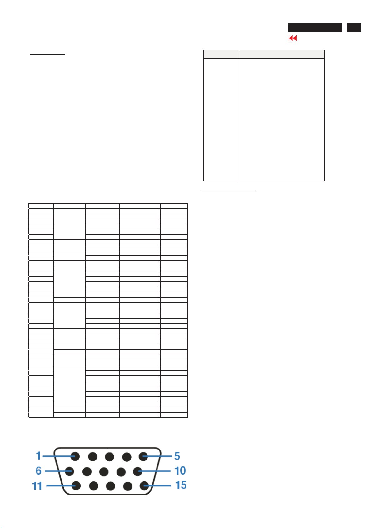
Input signal Pin assignment:
"
ees
- 160 Hz
67(35.0k) 30.240 MAC -º
85(37.8k) 31.500 VESA
85(37.927k) 35.500 VESA
90(60.4k) 65.227 SIEMENS
90(72.54K) 99.82 SIEMENS
85(77.090K) 121.500 VESA
85(85.938k) 148.500 VESA
85(91.146k) 157.500 VESA
75(93.75k) 202.50 VESA
PIN No. SIGNAL
1Red
2Green
3Blue
4Sense (GND)
5Self Test
6RedGND
7Green GND
8 Blue GND
9 Notconnect
10 Sync GND
11 Sense (GND)
12 Bi-directional data(SDA)
13 H-sync
14V-sync
15 DDC Data clock(SCL)
II. Picture Performance
1. Displaysize
Recommended:355x265mm
Maximum : 360 x270mm
2. Maxvideopixel :234Mhz
3. Rise/Fall time :<6.5ns/<6.5ns
4. Misconvergence
(A/C zone):£ 0.25 / 0.35 (Zone A/Cis 0.3 / 0.4 When ? 45kHz).
center:£ 0.
5. Geometry distortion :
|Top|, |Bottom| : : £ 2.0 mm
|Left|, |Right|:£ 2.0 mm
ôTop + Bottom ô : £ 3.5 mm
ôLeft + Rightô : £ 3.5 mm
Waviness per50 mm:1.0 mm max. at maximum videosize
Slope polarit
Tilt : £ 2.0mm
6.Image rotation : 1 degree adjustable
7. Horizontal /Vertical linearity:
12 equal blocks along horizontal axis,
9equal blocks alongvertical axis. (see Fig-1)
Horizontal frequenc
Horizontal non-linearity: £ 7.5 % £ 6.5 % £ 6 %
Vertical non-linearity: £ 5% £ 5% £ 5%
Horizontal two adjacent: £ 6 % £ 6 % £ 5%
Vertical two adjacent: £ 5% £ 5% £ 5%
H. linearity = ----------------------- x 100%
V. linearit
8. Image stability afterwarm -up 30 minutes.
9. Brightness uniformity : >75%
10.White uni
11. Display Centering:|A-B|or|C-D|<6 mm(for all preset modes)
12. White color CIE coordinates
@ 9300K ±27MPCD :x=0.283 +/- 0.015
@ 6500K ± 27MPCD :x=0.313 +/- 0.015
@5500K ±27MPCD :x=0.33
13.White tracking: +/- 0.015on centerwith light output from 3
FL tomaxFL.
14. Brightness output:(9300 K) 68.67K/85Hz
Brightness Contrast FW Pattern10X10cmblock
ControlControl fL fL
Min Min < 0.2
CenterMin £ 0.25
CenterMax 30 +/- 2.5 41 +/ -
y changes: 1.0 mm max.
y<33KHz 33K~ 65KHz >65KHz
Xmax. - Xmin
Xmax. + Xmin.
Ymax. - Ymin
y = ------------------------ x 100%
Ymax. + Ymin.
As a function of brightness : < 1.0 %
As a function of supply input voltage:<1.0 %
As a function of temperature :<1.0 %
formity:x,y<±0.015
+/-
+/-
+/-
@sRGB :x=0.313 +/- 0.015
15
+/-
y=0.297+/- 0.015
y=0.329 +/- 0.015
2+/-0.015
y=0.347 +/- 0.015
y=0.329 +/- 0.015
3
4
109B6 CRT
Go to cover page
Technical Data
14.1.sRGBluminance (Full white pattern): at 68.67K/85Hz, regardless
of brightness and contrastcontrols: 23 +/- 2.5 FL
15.Image shift range:Horizontal:> 10 mm, +/-3 from center to each side.
III. Customer Relev
1.Front Controls:Contrasttactswitch control
(Leftto Right) Brightness tact switch control
2. Rear Control : 15-pin D
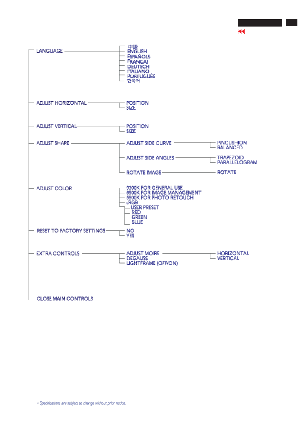
Digital OSDControls
-Language .Chinese
- Zoom .Zoom
-Adjust Horizontal .Position
-Adjust Vertical Position
-Adjust Shape .Adjust sidecurve .Pincushi
-AdjustColor .9300Kforgeneral use
- Reset tofactory settin
-Extracontrols.Adjust moire .Horizontal
-Model select (underfactotory mode) CPTCRT:set 109B6 CPT ON
(More details about structureare provided in SoftwareCRS)
3. RearInter connection:Power Cord: 1.8 m plugable,3leadwith
4. DDC : Compliant w
**Note1: 78&79 Factory code
Brazil :HC(48H,43H)
Chung-Li : TY(54H,59H)
Delta :GK(47H,4BH)
Suzhou : BZ(42H,5AH)
Juarez : YA(59H,41H)
Shenzshen : CX(43H,58H)
Szombathely:HD(48H,44H)
Raleigh :IO(49H,4FH)
Series No. address : 82,83,84,85,86,87,88,89
Vertical:> 8 mm, +/-2 from center to each side.
ance
(With DecreaseandIncrease)
(With DecreaseandIncrease)
OSD menu tact switch control
Poweron/off button
.English
Espanol
Francais
Deutsch
Italiano
.Portuguese
.Korean
.Adjust sideangles. Trapezoid
.sRGB
gs .No
.yes
Degauss
.LightFrame <Off On >
.Serial No.
Resolution
.Frequency
LPD &SDI CRT:set 109B6 LG & SDION
.SWDDC set ON
.LF ONOSD set
.LF3 set ON
- Close main controls
I/F connectors : 15pin 1.8m D-sub flying in cable
See DDC DATA
Software
Hardware
-sub I/F cable.
.Size
.Size
.Parallelogram
.Rotate image .Rotate
.6500Kforimage management
.5500Kforphotoretouch
.UserPreset R,G,B
.Vertical
ON
ground lead
ith the VESA DDC2B standards
DDC1
on
.Balanced
DDC2B
V
5. MainsVoltageRange: 195-264 or 90-264 V
6 Input Line Frequency: 47-63Hz
7. Power consumption :< 75W (at 220Vac mains)
< 78W (at 110Vac mains)
8. PowerLED green (non-protruding)
9. PowerMana
Functionality: Status
10. Low radiation : TCO/MPRº
11.SeparatedEHT :Yes
12. DAF : Yes
13. Self test :Yes
1.MTBF:>75000 hr. (excl. CRT)
2. Target F. C.R.:target
3. Environment :operating/non-operating
Temperature0to 40 -25 to 65
Humidity 10 % to 90 %5%to 95%
Altitude: 10000 ft 39000 ft
Shock/vibration :According DSD standard
4.Environmental issu
1.Safety & Ergonomics:UL1950
2. EMI/RFI/EMS :EN55022 class B
EMS: EN61000-4-3(80% 1KHz AM modulation)picture jitter 4mm
3. X-Ray:DHHS 21CFR SubchapterJ
4.EMC standards : EN 50082-1
5. Low Radiation : TCO/MPRº
6. Compatibility PC99,Windows2
VI. ApprobationCompliance
1. Approvals&Certifications: UL, CSA, SEMKO, TUV/GS,
gement TCO-99,EPAandE2000
On green (normal operation)
Off flash green (< 1.0W)
£ 2%(first12months)
no condensation incl. condensation
es:CRT, cabinet and componentsmust be
free of CFC's,
PBBE's, PBDE's, cadmium, (TCO99)
All documentation printedon recycledpaper
Accessoriespacked in bufferwithoutadditional
wrapping
All other issues according CE and BUEn
Policy
V. Regulatory Compliance
CSA-22.2 No. 950-M89
IEC950
ZH1/618
EN60950
EMKO-TSE (74SEC)207/94
ISO 9241-3 / ISO 9241-7 / ISO 9241-8
E-2000,EPA,Nutek, TUV/GS,TCO.
Rontgen Verordnung Rov 1987-01-08
000,Windows ME, PC2001
FCC Class B, DOC. Class B, BZT,VCCI class 2,
FDA(DHHS), Rontgen, TUV/Ergonomics, CE(98,
prepared), B”-mark for Poland, C tick for Australia
"- "
rms
LEDcolor
IV. Quality
shipping/storage
butexcl.rain
vironmental
FCC Part15(class B)
D.O.C.(class B)
CISPR 22 (class B
C-tick, CE(Europe)
EN 60555-2
Windows XP.
)
</=
PSB(Singapore), BCIQ, CCIB
Installation
109B6 CRT
Go to cover page
5
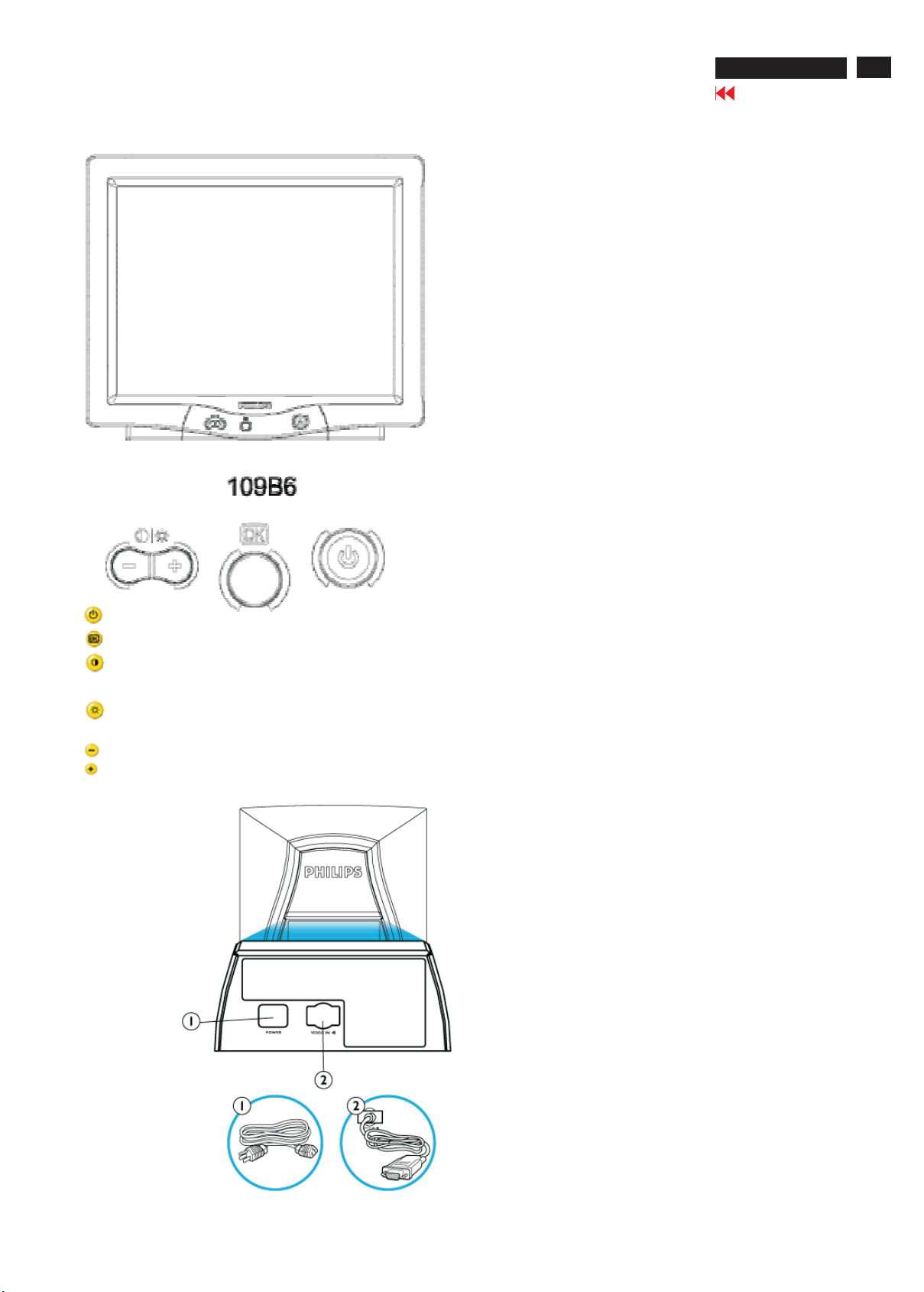
Front View
1.Power in - attach power cable here.
2. VideoIn- this is a cablewhich is already attached to
your monitor. Connectthe other end of the cable to your PC.
Power button switches your monitor on.
OK button which when pressed will take you to the OSD controls
Contrast hotkey. Whenthe "-" button is pressed, the adjustment
controls for the CONTRAST will show up.
Brightness hotkey. Whenthe "+" button is pressed, the adjustment
controls for
"-" and "+" buttons, are used for adjusting the OSD ofyour monitor
RearView
BRIGHTNESS will show up.
6
109B6 CRT
Trouble Shooting
Go to cover page
Having thisproblem? Check theseitems
Make sure the Power cable isplugged into the
power outlet and back of the monitor.
No Picture Power button in the front ofyour monitor should be
in the ON position.
(Power LED not lit)Disconnectthemonitor from the power outlet
for about one minute.
No Picture Make sure the computer is turned
Make sure the monitor cable isproperlyconnected to your computer.
(Power LED isflashing green) Check to see if the monitor cable has bent pins.
The Energy Saving feature may be activated
No Picture Make sure the Brightness and Contrast controlsare set correctly.
sure the monitor cable isproperlyconnected to your computer.
Make
(Power LED is green) Check to see if the monitor cable has bent pins.
Make sure the computer Power button is on.
Screen doesn't show Make sure the monitor cable isproperlyconnected to your computer.
sorefer to the Quick Start Guide).
(Al
when you turn on the monitor Check to see if the monitor cable has bent pins.
Make sure the computer is turned on.
on.
No color or intermittent color If you are using a non-VESA-DDC standardvideo card,
turn the DDC1 /2B feature Off.
The picture may needdeg
Color appears blotchy Remove any nearbymagnetic objects.
Facethemonitor toward the East for the best picture quality.
Check the Color Temperature.
Missing one or more colors Make sure the monitor cable isproperlyconnected to your computer.
to see if the monitor cable has bent pins.
Check
Adjust the Brightness and Contrast controls.
DimPicture Check your video cardand it's owner's manualinstructions
for it may be a non-VESA-DDCStandardcard.
AdjusttheHorizontal and/or VerticalSize.
Picture is
Edges of the picture are not square Adjustthegeometry
Picture has a double image Eliminate the useofavideo extension cable and/or video switchbox.
Picture i
Unstable Picture Increase your refreshrate
Problemwith OnScreen Display Refer to the instructionsand troubleshooting information in that chapter.
too large or too small AdjusttheZoom.
Facethemonitor toward the East for the best picture quality
s not sharp Check to make sure Moiré isswitched off.
AdjustSyncInput.
aussing.
OSD Tree
109B6 CRT
Go to cover page
7
8
Go to cover page
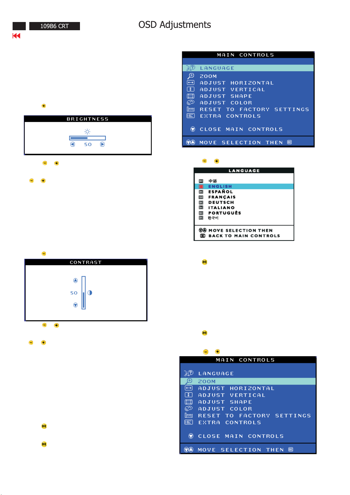
The OSD Controls
BRIGHTNESS
To adjust your screen's brightness, follow the steps below. Brightness
is the overall intensity of the light coming from the screen. A 50%
brightness is recommended.
1) Press the button on the monitor. The BRIGHTNESS window
appears.
2) Press the or button to adjust the brightness.
3) When the brightness is adjusted to the level desired. Stop pressing
the or button and after three seconds the BRIGHTNESS
window will disappear with the new adjustment saved.
Smart Help After the BRIGHTNESS window has disappeared, to
continue to the CONTRAST window, follow the steps under CONTRAST.
CONTRAST
To adjust your screen's contrast, follow the steps bellow. Contrast is
thedifferencebetweenthelightanddarkareasonthescreen.A100%
contrast is recommended.
1) Press the button on the monitor. The CONTRAST window appears.
2) Press the or button to adjust the contrast.
3) When the contrast is adjusted to the level desired, stop pressing
the or button and after three seconds the CONTRAST window
will disappear with the new adjustment saved.
3) Press the or button until the desired language is highlighted.
4) press the button to confirm your selection and return to MAIN
CONTROLS window. Close MAIN CONTROLS will be highlighted...
Smart Help After returning to MAIN CONTROLS......to continue to
ZOOM.
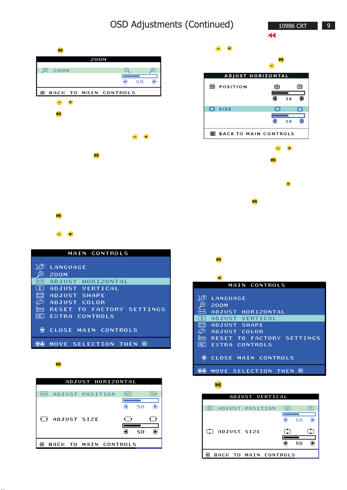
ZOOM
ZOOM increase or decrease the size of the images on your screen.
To adjust the ZOOM follow the steps below.
1) Press the button on the monitors. The MAIN CONTROLS
window appears.
2) Press the or button until ZOOM is highlighted.
Smart Help After the CONTRAST window has disappeared, to continue
to the MAIN CONTROLS, follow the steps under LANGUAGE.
LANGUAGE
The ON SCREEN DISPLAY shows its setting in one of eight languages.
The default is English, but you can select French, Spanish, German,
Italian, simplify-Chinese, Korea, Brazilian or Portuguese.
1) Press the button the monitor. The MAIN CONTROLS window
appears. LANGUAGE should be highlighted.
2) Press the button again. The LANGUAGE window appears.
Go to cover page
3) Press the button. The ZOOM window appears.
4) Press the or button to adjust ZOOM.
5) Press the button to confirm your selection and return to the MAIN
CONTROLS window. Close MAIN CONTROLS will be highlighted.
Smart Help After returning to MAIN CONTROLS...
... to continue to ADJUST HORIZONTAL, press the or button until
ADJUST HORIZONTAL is highlighted. Next, follow steps3-7 under ADJUST
HORIZONTAL.
... To exit completely, press the button.
ADJUST HORIZONTAL
ADJUST HORIZONTAL under ADJUST HORIZONTAL shifts the image on
your screen either to the left or right. Use this feature if your image does
not appear centered. ADJUST SIZE under ADJUST HORIZONTAL expands
or controls the image on your screen, pushing it out toward the left and
right sides or pulling it in toward the center.
1) Press the button on the monitor. The MAIN CONTROLS window
appears.
2) Press the or button until ADJUST HORIZONTAL is highlighted.
4) Press the or button to move the image to the left or right.
5) When the position is adjusted, press the button to return to
MAIN CONTROLS window, or press the to highlight ADJUST SIZE.
6) To adjust the horizontal size, press the or button.
7) When the size is adjusted, press the button to return to MAIN
CONTROLS window. CLOSE MAIN CONTROLS will be highlighted.
Smart Help After returning to MAIN CONTROLS...
... To continue to ADJUST VERTICAL, press the button until ADJUST
VERTICAL is highlighted. Next, start with step 3 under ADJUST VERTICAL
and follow the directions.
...To exit completely, press the button.
ADJUST VERTICAL
ADJUST POSITION under ADJUST VERTICAL shifts the image on your
screen either up or down. Use this feature if your image does not
appear centered. ADJUST VERTICAL expands or controls the image on
your screen, pushing it out toward the top or bottom or pulling it in
toward the center.
3) Press the button. The ADJUST HORIZONTAL window appears.
ADJUST POSITION should be highlighted.
1) Press the button on the monitor. The MAIN CONTROLS window
appears.
2) Press the button until ADJUST VERTICAL is highlighted.
3) Press the button. The ADJUST VERTICAL window appears.
ADJUST POSITION should be highlighted.

Go to cover page
4) Press the or button to move the image up or down.
5) When the position is adjusted, press the button to return to
MAIN CONTROLS window, or press the button to highlight
ADJUST SIZE.
6) To adjust the vertical size, press the or button.
7) When the size is adjusted, press the button to return to MAIN
CONTROLS window. CLOSE MAIN CONTROLS will be highlighted.
Smart Help After returning to MAIN CONTROLS...
... To continue to ADJUST SHAPE, press the button until ADJUST
SHAPE is highlighted. Next, start with step under ADJUST SHAPE and
follow the directions.
... To exit completely, press the button.
4) Press the button. The SIDE CURVE window appears.
PINCUSHION should be highlighted.
5) To adjust the pincushion, press the or button, then
press the button to save your selection.
6) When the pincushion is adjusted, press the button to
highlight BALANCE or press the button to return to the
ADJUST SHAPE window.
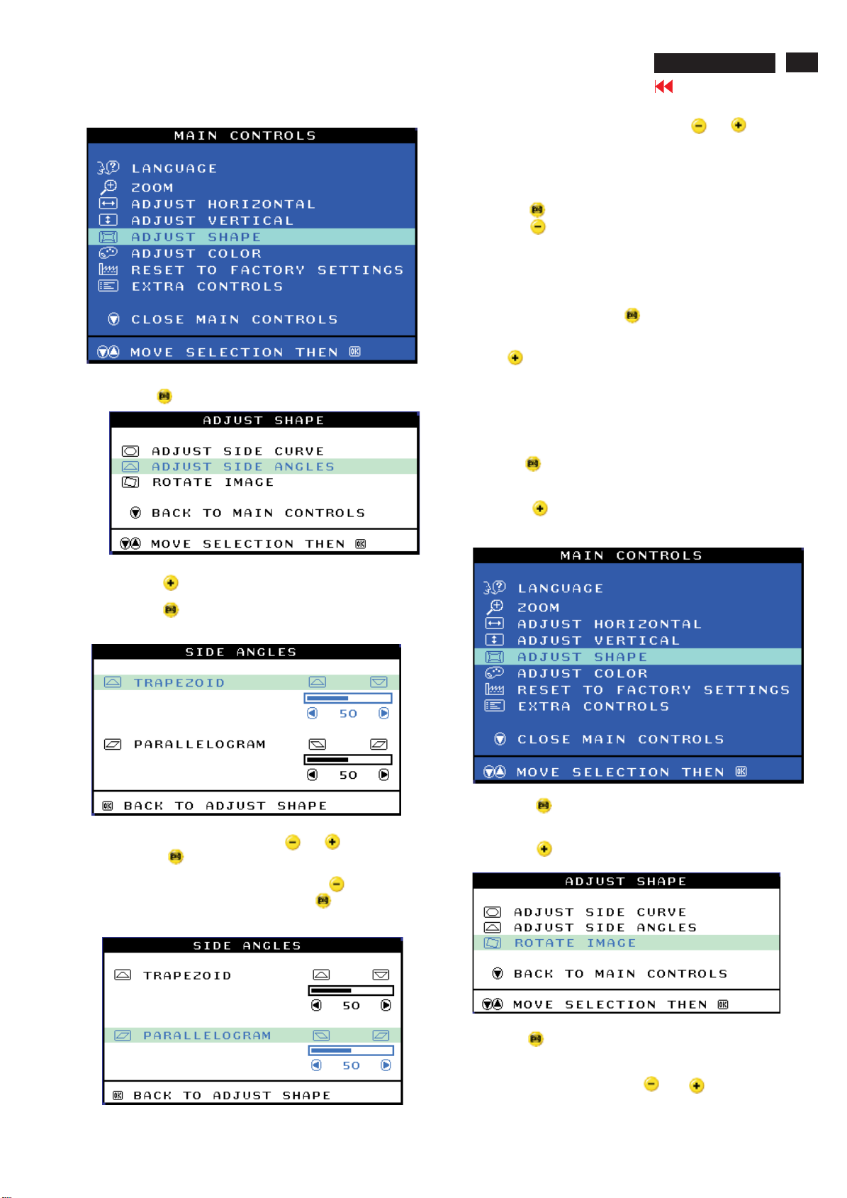
ADJUST SHAPE
ADJUST SIDE CURVE
ADJUST SIDE CURVE under ADJUST SHAPE allows you to adjust two
of the five preset options. These two options are PINCUSHION and
BALANCED pincushion. Note: use these features only when the picture
is not square.
1) Press the button on the monitor. The MAIN CONTROLS window
appears.
2) Press the button until ADJUST SHAPE is highlighted.
3) Press the button. The ADJUST SHAPE window appears.
ADJUST SIDE CURVE should be highlighted.
7) To adjust the balanced, press the or button.
8) When the balanced is adjusted, press the button. BACK TO
ADJUST SHAPE will be highlighted.
9) Press the button to return to the ADJUST SHAPE window, then
press the button until ADJUST SIDE ANGLES is highlighted.
Smart Help After returning to MAIN CONTROLS...
... To continue to ADJUST SIDE ANGLES, start with step 5 under
ADJUST SIDE ANGLES and follow the directions.
...To exit completely. Press the button twice.
ADJUST SIDE ANGLES
ADJUST SIDE ANGLES under ADJUST SHAPE allows you to adjust
two of the five preset options. These two options are TRAPEZOID
and PARALLELOGRAM. Note: use these features only when the
picture is not square.
1) Press the button on the monitor. The MAIN CONTROLS
window appears.
2) Press the button until ADJUST SHAPE is highlighted.
OSD Adjustments (Continued)
8) To adjust the PARALLELOGRAM, press the or button.
9) When the parallelogram is adjusted, press the button to return
to the ADJUST SHAPE window. BACK TO MAIN CONTROLS window
will be highlighted.
10) Press the button to return to the MAIN CONTROLS window, or
press the button until ROTATE IMAGE is highlighted.
Smart Help After returning to MAIN CONTROLS...
... To continue to ROTATE IMAGE, start with step 5 under ROTATE IMAGE
and follow the directions.
...To exit a completely, press the button twice.
...To adjust only the PARALLELOGRAM, follow steps 1-4 above, then
press the button, and follow steps 7-9
109B6 CRT
Go to cover page
11
3) Press the button. The ADJUST SHAPE window appears.
ADJUST SIDE CURVE should be highlighted.
4) Press the button to highlight ADJUST SIDE ANGLES.
5) Press the button. The SIDE ANGLES window appears.
TRAPEZOID should be highlighted.
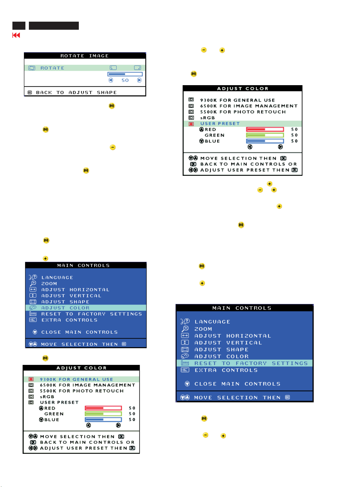
ROTATE IMAGE
ROTATE IMAGE under ADJUST SHAPE allows you to adjust the rotated
image. Note : use this feature only when the picture is not square.
1) Press the button on the monitor. The MAIN CONTROLS window
appears.
2) Press the button until ADJUST SHAPE is highlighted.
6) To adjust the trapezoid, press the or button, then
press the button to save your selection.
7) When the trapezoid is adjusted, press the button to
highlight PARALLELOGRAM or press the button to return
to the ADJUST SHAPE window.
3) Press the button. The ADJUST SHAPE window appears.
ADJUST SIDE CURVE should be highlighted.
4) Press the button until ROTATE IMAGE is highlighted.
5) Press the button. The ROTATE IMAGE window appears.
ROTATE will be highlighted.
6) To adjust the rotation, press the or button.
12
109B6 CRT
OSD Adjustments (Continued)
Go to cover page
7) When the rotation is adjusted, press the button to return to
the ADJUST SHAPE window. BACK TO MAIN CONTROLS should
be highlighted.
8) Press the button to return to MAIN CONTROLS.
Smart Help After returning to MAIN CONTROLS...
... To continue to ADJUST COLOR, press the button until ADJUST
COLOR is highlighted. Next, start with step 3 under ADJUST COLOR
and follow the directions.
... To exit completely, press the button twice.
4) Press the or button to highlight 9300K for GENERAL
USE. 6500K for GAMES, or USER PRESET.
5) Once you have highlighted the GENERAL USE OR GAMES, press
the button to confirm your selection and return to the MAIN
CONTROLS window. CLOSE MAIN CONTROLS will be highlighted.
ADJUST COLOR
Your monitor has two preset options you can choose from. The first
option is for GENERAL USE, which is fine for most applications. The
second option is for GAMES, which is for playing computer games.
When you select one of these options, the monitor automatically
adjusts itself to that option. There is also a third option, USER PRESET,
which allows you to adjust the colors on your screen to a setting you
desire.
1) Press the button on the monitor. The MAIN CONTROLS window
appears.
2) Press the button until ADJUST COLOR is highlighted.
6) If USER PRESET is highlighted, press the button to highlight
RED(GREEN BLUE). Next, press the or button to adjust
the color red(green blue).
7) When all adjustments are complete, press the button until
RESET TO FACTORY SETTINGS is highlighted. Next, start with
step 3 under RESET TO FACTORY SETTINGS.
...To exit completely, press the button.
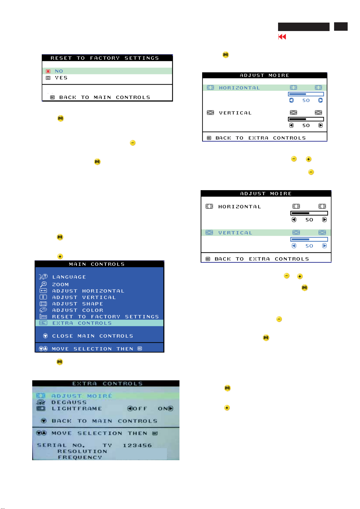
RESETTOFACTORYSETTINGS
RESETTOFACTORYSETTINGSreturnseverythinginallthewindows
to factory presets.
1) Press the button on the monitor. The MAIN CONTROLS window
appears.
2) Press the button until RESET TO FACTORY SETTING is
highlighted.
3) Press the button. The ADJUST COLOR window appears.
3) Press the button. The RESET TO FACTORY SETTINGS
window appears.
4) Press the or button to select YES or NO. NO is the
defaults. YES return all settings to their original factory
adjustments.
OSD Adjustments (Continued)
5) Press the button to confirm your selection and return to the MAIN
CONTROLS window. CLOSE MAIN CONTROLS will be highlighted.
Smart Help After returning to MAIN CONTROLS...
... To continue to EXTRA CONTROLS, press the button until EXTRA
CONTROLS is highlighted. Next, start with step 3 under EXTRA CONTROLS.
109B6 CRT
Go to cover page
4) Press the button. The ADJUST MOIRE window appears.
HORIZONTAL will be highlighted.
13
...To exit completely, press the button.
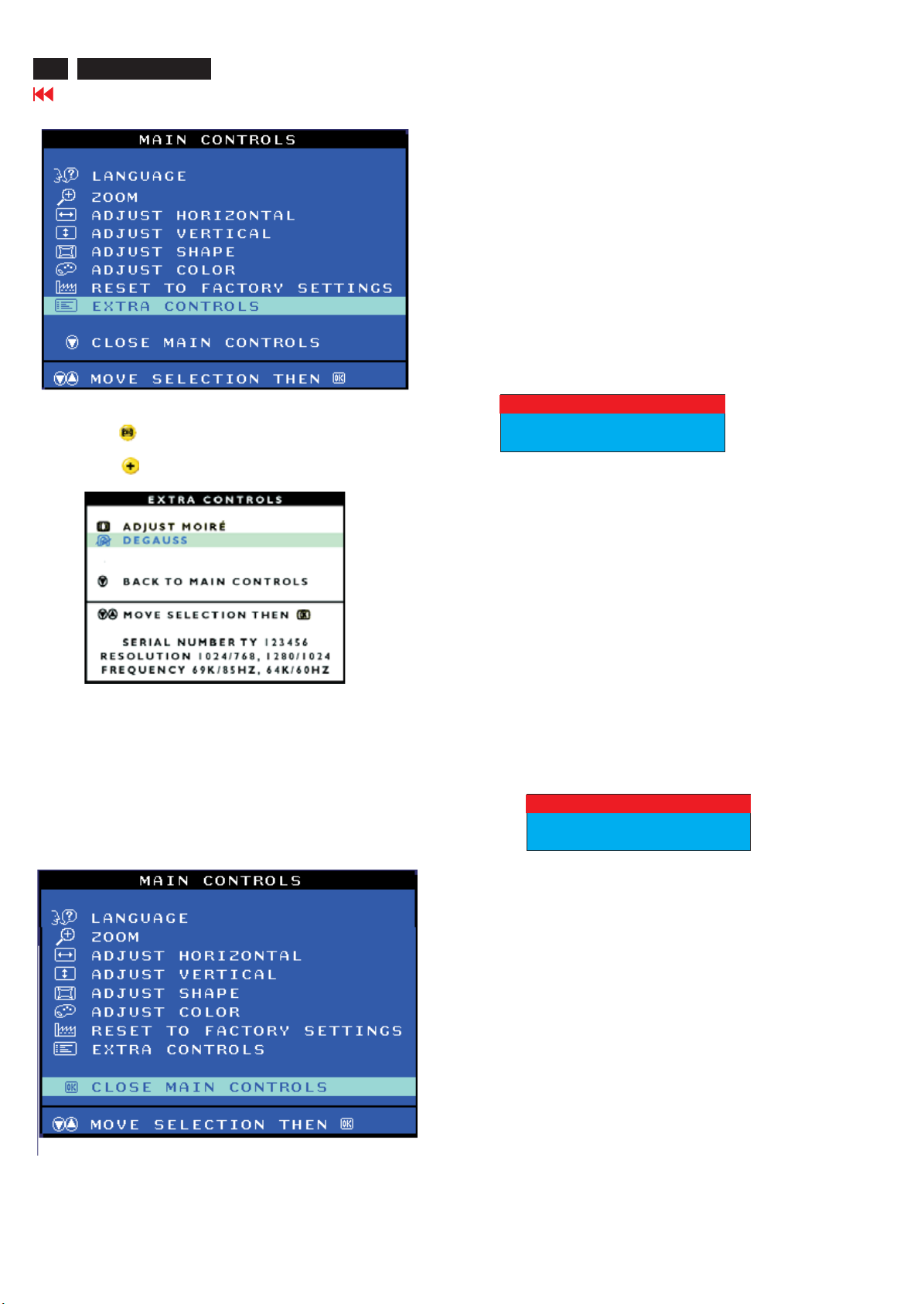
EXTRA CONTROLS
ADJUST MOIRE
EXTRA CONTROLS is a set of three feature, including ADJUST MOIRE.
Moire is a fringe patten arising from the interference between two
superimposed line pattens. To adjust your moire, follow the steps below.
Note: use only if necessary. By activating ADJUST MOIRE, sharpness can
be affected.
1) Press the button on the monitor. The MAIN CONTROLS window
appears.
2) Press the button until EXTRA CONTROLS is highlighted.
5) To adjust the horizontal moire, press the or button.
6) When the horizontal moire is adjusted, press the button to
highlight VERTICAL.
7) To adjust the vertical moire, press the or button.
8) When the vertical moire is adjusted, press the button to return
to the EXTRA CONTROLS window. BACK TO MAIN CONTROLS will
be highlighted.
Smart Help After returning to MAIN CONTROLS...
... To continue to DEGAUSS, press the button until DEGAUSS is
highlighted. Next, start with step 3 under EXTRA CONTROLS,
DEGAUSS.
...To exit completely, press the button.
3) Press the button. The EXTRA CONTROLS window appears.
ADJUST MOIRE will be highlighted.
1280X1024
80K/75HZ
DEGAUSS
EXTRA CONTROLS is a set of three feature, including DEGAUSS.
Degaussing remove electromagnetic build up that may distort the color
on your screen.
1) Press the button on the monitor. The MAIN CONTROLS window
appears.
2) Press the button until EXTRA CONTROLS is highlighted.
14
109B6 CRT
Go to cover page
OSD Adjustments (Continued)
Monitor specific troubleshooting
Self-test Feature Check(STFC)
Your monitor provides a self-test feature that allows you to check
whether your monitor is functioning properly. If your monitor and
computer are properly connected but the monitor screen remains
dark, run the monitor self-test by performing the following steps:
1. Turn off both your computer and the monitor.
2. Unplug the video cable from the back of the computer.
3. Turn on the monitor.
If the monitor is functioning properly, you will see a OSD message
asshowninthefollowingillustration:
3) Press the button. The EXTRA CONTROLS window appears.
ADJUST MOIRE will be highlighted.
4) Press the button until DEGAUSS is highlighted.
5) To degauss your screen, press the button. Your screen will be
degaussed, then the MAIN CONTROLS will reappear. CLOSE MAIN
CONTROLS will be highlighted.
Smart Help After returning to MAIN CONTROLS...
...To exit completely, press the button.
CLOSE MAIN CONTROLS
CHECK SIGNAL CABLE
This box also appears during normal system operation if the video
cable becomes disconnected or damaged. This box will remain on
for one minute, go off five seconds. Then on for one minute, and will
repeat cycle.
1. Turn off your monitor and reconnect the video cable:
then turn on both your computer and the monitor.
2. While in self-test mode, the LED remains green and the pattern
remains on and stationary.
If your monitor screen still remains dark after you use the previous
procedure, check your video controller and computer system; your
monitor is functioning properly.
NO SIGNAL INPUT
If there is something wrong with the input signal, a message appears
on the screen although the power indicator LED is still on. The
message may indicate that the monitor is NO SIGNAL INPUT or that
you need to check the signal cable.
NO SIGNAL INPUT
OSD Adjustments (Continued)
109B6 CRT
Go to cover page
15
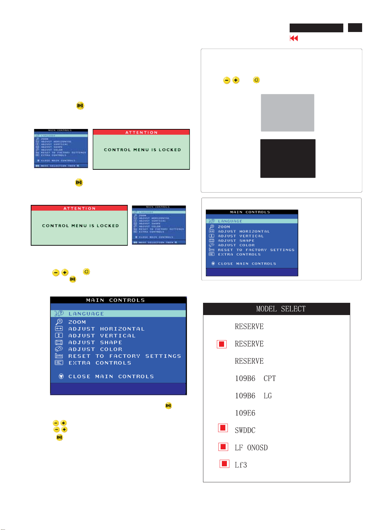
OSD LOCK
OSD LOCK is a feature which disables the OSD controls. It can be used
when the monitor is set up for demonstration purposes or when
adjustment of the OSD is not desirable.
Switch on OSD LOCK feature:
Press and hold the button continuously for 15 seconds.
Release the button when the message
" CONTROL MENU IS LOCKED" appears.
Switch off OSD lock feature:
Press and hold the button continuously for 15 seconds or until
the message window ''CONTROL MENU IS LOCKED''disappears. And
''MAIN CONTROLS'' appears.
To access BURN IN mode
First of all, monitor displays an image.
1. Disconnect the video cable(interface cable).
2. Turn off monitor
3. Press and simultaneously on the front control panel,
then the BURN IN mode comes on the screen of monitor as below.
50 seconds around
5 second around
repeat
4. Reconnect the video cable, then return the normal image.
SERVICE MODE (indication-factory mode)
37067
To access factory mode
1. Turn off monitor(don't turn off PC)
2. Press and simultaneously on the front control pane,
then press , wait until the OSD menu with characters
V32 107T6 V0.24 20040303 (below OSD menu) come on the screen
of monitor.
MODEL SELECT
MODEL SELECT
Factory
-----------
-----------
Mode
Indicator
3. If OSD menu disappears on the screen of monitor, press
again(anytime), then the OSD menu comes on the screen again.
4. Using : to select OSD menu.
5. Using : to increase or decrease the setting.
6. Using : to access/confirm the selection.
V40 109 V0.12 20040621
MODEL SELECT
V32 107T6 V0.24 20040303V40 109 V0.12 20040621
Default setting of MODEL SELECT
To leave factory mode
7. After alignment of factory mode, turn off monitor(if you do not run
off monitor, the OSD menu is always at the factory mode), then turn
on monitor again (at this moment, the OSD menu goes back to user
mode.)
16
109B6 CRT
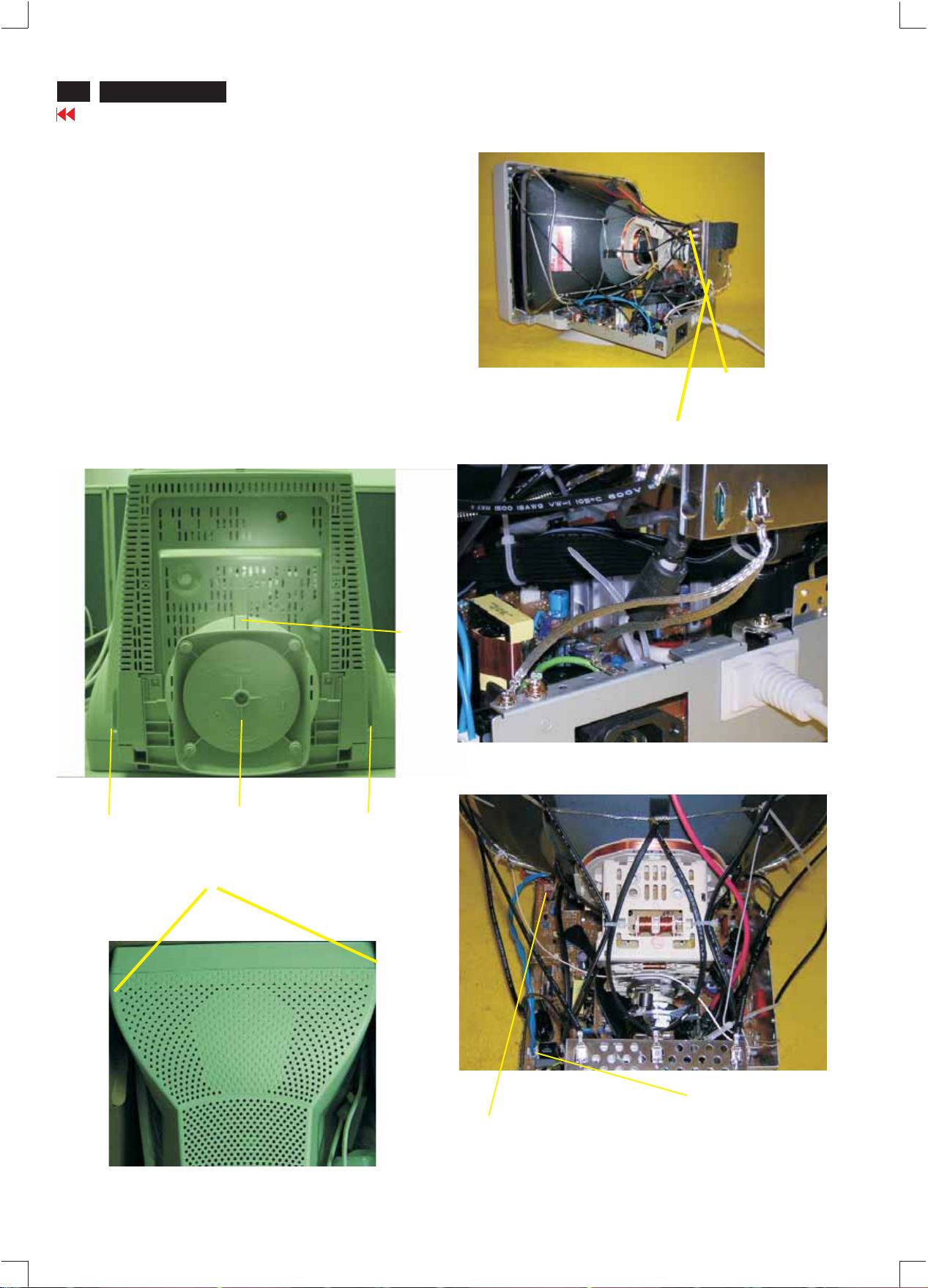
Mechanical Instructions
Go to cover page
0. General
To be able to perform measurements and repairs on the "circuit
boards", these unit should placed in the service position first.
1. Remove the rear cover in Fig. 1 and Fig. 2.
-Remove 4 screws as shown
-Remove back cover as shown
-Remove pedestal as shown
2. Video panel
-Disconnect the wire between metal shield of video panel and
CRT neck as shown in Fig. 3.
-Disconnect the CRT grounding from Video panel.
-Remove screw grounding and grounding wire in Fig. 4.
3. Main board connector in Fig. 5.
-Disconnect york wire
-Disconnect rotation connector
-Disconnect control board connector
-Remove Screw for fixed I/F cable
-Remove signal connector
-Remove degaussing wire connector
Clip
Video Panel
=
=
=
=
Screw-grounding
CRT grounding wire
Fig. 3
=
=
=
=
=
=
=
=
=
=
=
=
=
=
=
Fig. 4
>
Screw
Pedestal ass'y
Fig. 1
Screw
Fig. 2
Screw
Degaussing wire connector
Control connector
Fig. 5
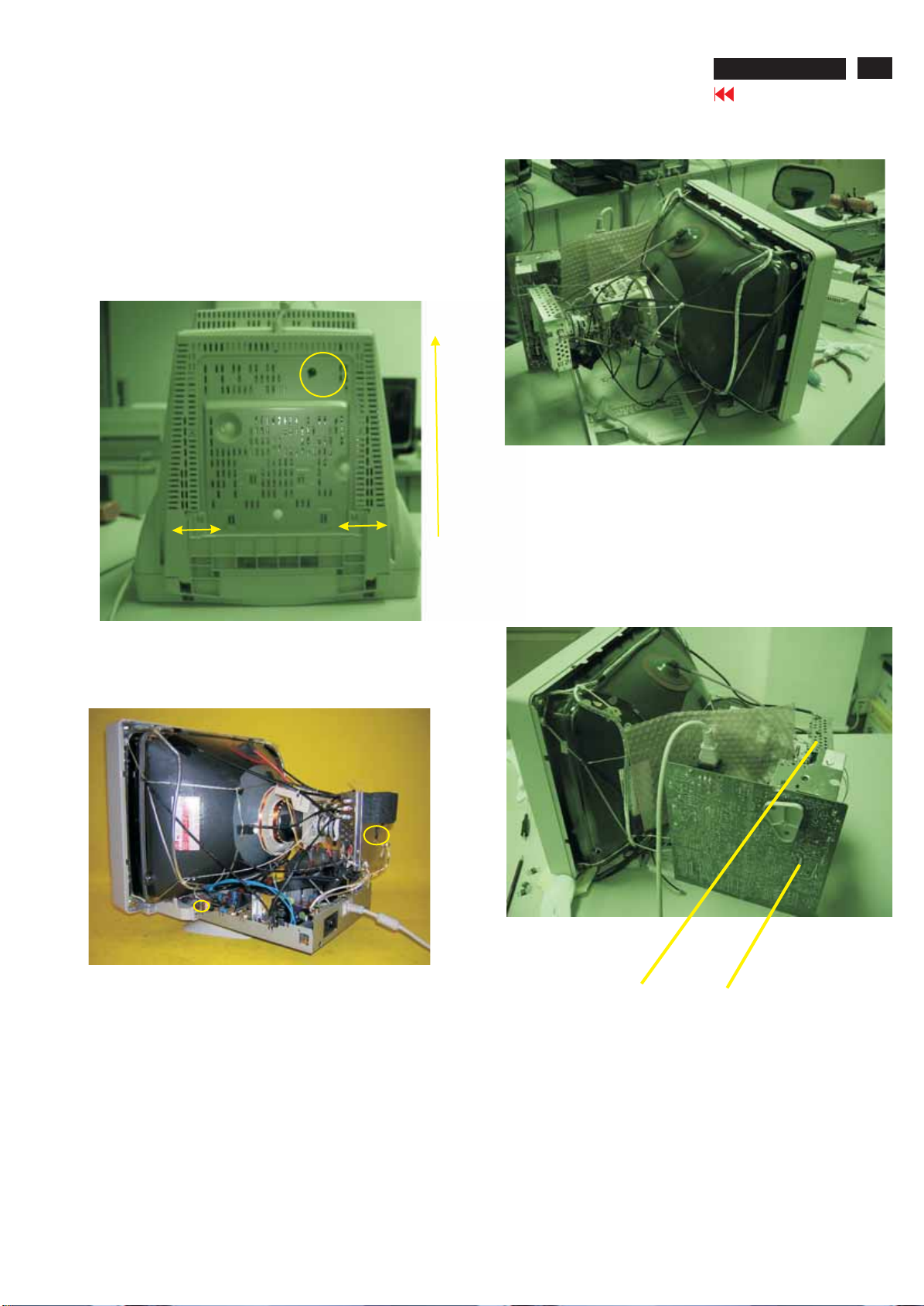
Mechanical Instructions
4. Main panel with Bottom Tray
-Remove the screws for disconnect the Bottom tray as Fig. 6.
-Open the click and remove the screws on the main board from
fig. 6 to fig.7.
5. SERVICE POSITION
-reconnect connectors, some wires and panels (chassis),
service position can be available for DC/AC measurement
as shown inFig.8 Fig. 9.
Screw
Pull-up
109B6 CRT
Go to cover page
17
Fig.7
Fig. 6
Fig. 6
Fig. 8
Video panel
Fig. 9 SERVICE POSITION
Main panel
Fig.9
18
109B6 CRT
DDC Instructions
Go to cover page
General
DDC Data Re-programming
In case the DDC data memory IC or main EEPROM which storage all
factory settings were replaced due to a defect, the serial numbers have
to be re-programmed" ".
It is advised to re-soldered DDC IC and main EEPROM from the old
board onto the new board if circuit board have been replaced, in this
case the DDC data does not need to be re-programmed.
Additional information
Additional information about DDC (Display Data Channel) may be
obtained from Video Electronics Standards Association (VESA). Extended
Display Identification Data(EDID) information may be also obtained from
VESA.
Analog DDC IC, & EEPROM
System and equipment requirements
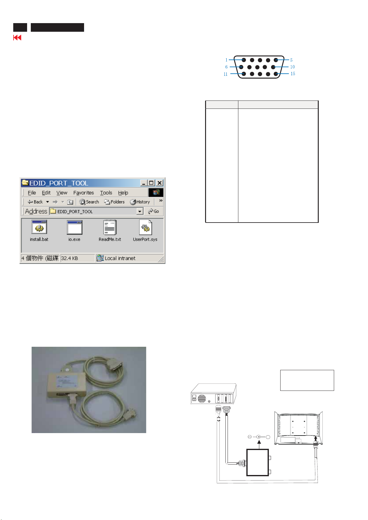
1. An i486 (or above) personal computer or compatible.
2. Microsoft operation system Windows 95/98 .
Y o Install the EDID_PORT_Tool under Win2000/XP . As
ou have t
Fig. 1 .
Pin assignment
15-pin D-Sub Connector
PIN No. SIGNAL
1Red
2 Green
3Blue
4 Sense (GND)
5 Self Test
6RedGND
7 Green GND
8BlueGND
9 Not connect
10 Sync GND
11 Sense (GND)
12 Bi-directional data(SDA)
13 H-sync
14 V-sync
15 DDC Data clock(SCL)
Fig. 1
A. Cody the "UserPort.sys" to C:\WINNT\system32\drivers(win2000)
C:\WINDOWS\system32\drivers(winXP)
B. Running " io.exe" everytime, Before you start to programming
edid data .
3. EDID301.EXE program
4. A/D Alignment kits (12NC: 3138 106 10079) shown as Fig. 2:
inclusion : a. Alignment box x1
Fig. 2
Configuration and procedure
There is no Hardware DDC (DDC IC) anymore. Main EEPROM stores
all factory settings and DDC data (EDID code) which is also called
Software DDC. The following section describes the connection and
procedure for Software DDC application. The main EEPROM can be reprogrammed by enabling '' factory memory data write'' function on the
DDC program (EDID301.EXE).
Initialize alignment box
In order to avoid that monitor entering power saving mode due
to sync will cut off by alignment box, it is necessary to initialize
alignment box before running programming software
(EDID301.EXE). Following steps show you the procedures and
connection.
Step 1: Supply 8-12V DC power source to the Alignment box by
plugging a DC power cord .
Step 2: Connecting printer cable and D-Sub cable of monitor as Fig. 3
PC
1=Power connector
2=D-SUB connector
109B6
b. Printer cable x1
c. (D-Sub) to (D-Sub) cable x1
Note: The EDID301.EXE is a windows-based program, which cannot
beruninMS-DOS.
To printer port (LTP1)
DC Power
8-12 V
To
Monitor
Printer
Port
To P C
+
----->
1
AC POWER
Fig. 3
----->
2
DDC Instructions (Continued)
109B6 CRT
Go to cover page
19
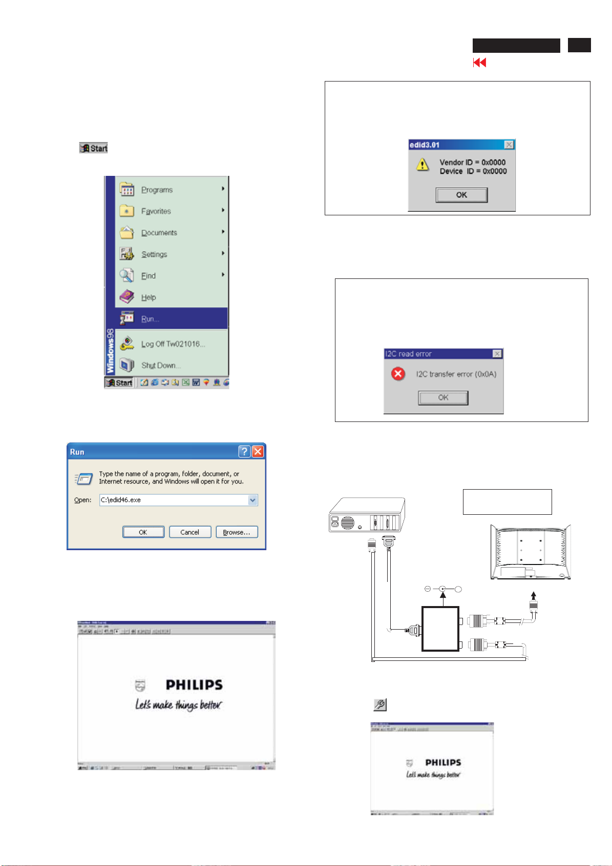
Step 3: Installation of EDID301.EXE
Method 1: Start on DDC program
Start Microsoft Windows.
1.Copy the Program"EDID301.EXE" in service manual cd-rom to C:\ .
2. Click , choose Run at start menu of Windows as shown
In Fig. 4.
Fig. 4
Note 1: If the connection is improper, you will see the following error
message (as shown in Fig. 7) before entering the main menu.
Meanwhile, the (read EDID) function will be disable. At this
time, please make sure all cables are connected correctly and
fixedly, and the procedure has been performed properly.
Fig. 7
Note 2: During the loading, EDID301 will verify the EDID data which
just loaded from monitor before proceed any further function,
once the data structure of EDID can not be recognized, the
following error message will appear on the screen as below.
Please confirm following steps to avoid this message.
1. The data structure of EDID was incorrect.
2. DDC IC that you are trying to load data is empty.
3. Wrong communication channel has set at configuration setup
windows.
4. Cables loosed or poor contact of connection.
3. At the submenu, type the letter of your computer's hard disk drive
followed by :EDID301 (for example, C:\EDID301, as shown in Fig. 5).
1
Fig. 5
4. Click button. The main menu appears (as shown in Fig. 6).OK
This is for initialize alignment box.
Fig. 8
Re-programming EEPROM(Software DDC IC)
Step 1: After initialize alignment box, connecting all cables and
box as shown in Fig. 9
PC
DC Power
8-12V
To printer port (LTP1)
Printer
Port
To PC Video port (D-sub)
Step 2: Read DDC data from monitor
1=Power connector
2=D-SUB connector
+
To
Monitor
To P C
AC IN
1
2
----->
----->
Fig. 9
Fig. 6
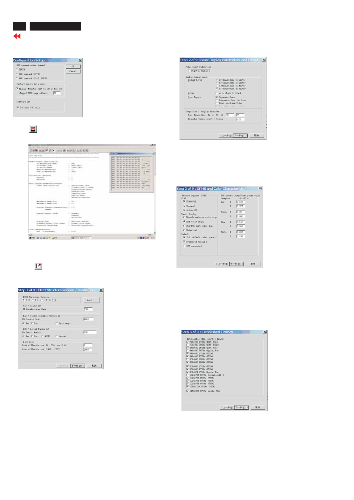
1. Click icon as shown in Fig. 10 from the tool bar to bring up
the Channels "Configuration Setup" windows as shown in Fig. 11.
Fig. 10
20
109B6 CRT
DDC Instructions (Continued)
Go to cover page
2. Select the DDC2B as the communication channel.
As shown in Fig. 11.
Fig. 11
3. Click OK button to confirm your selection.
4. Click icon (Read EDID function) to read DDC EDID data from
monitor. The EDID codes will display on screen as shown in Fig. 12.
Fig. 14
Don't close this screen. --->
Fig. 12
Step 3: Modify DDC data (verify EDID version, week, year)
1. Click (new function) icon from the tool bar, bring up
Step1of9asshowninFig.13.
EDID301 DDC application provides the function selection and
text change (select & fill out) from Step 1 to Step 9.
To Printer port
DC 8~12V
To Monitor
D-sub/DVI cable
2. Click , bring up Fig. 15.
3. Click , bring up Fig. 16.
Next
Next
Fig. 15
Fig. 13
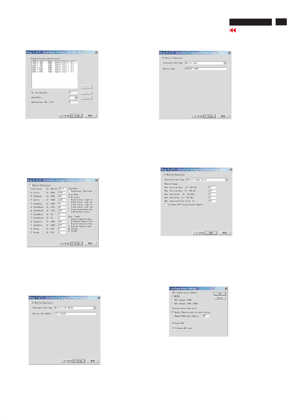
Step 4: Modify DDC data (Monitor Serial No.)
1. Click , bring up Fig. 14.
Next
Fig. 16
DDC Instructions (Continued)
109B6 CRT
Go to cover page
21
4. Click , bring up Fig. 17.Next
5. Click , bring up Fig. 18.Next
Fig. 17
7. Click , bring up Fig. 20.Next
Fig. 20
8. Click , bring up Fig. 21.Next
- Click Finish to exit the Step window.
8. Click , bring up Fig. 19.Next
Fig. 18
- Serial number can be filled up at this moment (for example,
TY 000130).
Fig. 21
Step 5: Write DDC data
1. Configuration should be as Fig. 22. And press OK.
Fig. 22
Fig. 19
22
109B6 CRT
Go to cover page
DDC Instructions (Continued)
2. Access Factory Mode
1). Turn off monitor.
2). [Push " " & " " buttons at the same time and hold it
] + [Press power " " button untill comes out "Windows screen"]
=>thenreleaseallbutton,thenpress ,waituntiltheOSDmenu
(below OSD menu) come on the Screen of the monitor (see Fig. 23).
V40 109 V0.12 20040621
Fig. 23
3. Click (Write EDID) icon from the tool bar to write DDC data.
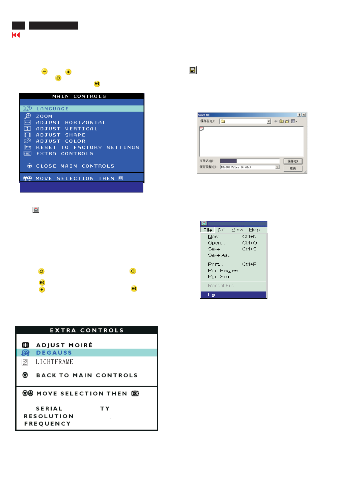
Step 6: Save DDC data
Sometimes, you may need to save DDC data as a text file for using
in other IC chip. To save DDC data, follow the steps below:
1. Click (Save) icon (or click "file"-> "save as") from the tool bar
And give a file name as shown in Fig. 25.
The file type is EDID46 file (*.ddc) which can be open in WordPad.
By using WordPad, the texts of DDC data & table (128 bytes, hex
code) can be modified. If DDC TEXTS & HEX Table are completely
correct, it can be saved as .ddc flie to re-load it into DDC IC for DDC
Data application.
109E6
109E-DDC
107T6-DDC
Fig. 25
2. Click .Save
Step 7: Exit DDC program
Pull down the File menu and select Exit as shown in Fig. 26.
4. Confirm Serial Number in User Mode
1) Press the button to turn off the monitor. Press the button
again to turn on the monitor.
2) Press the button to bring up the OSD main menu.
3) Press the button to select Extra Controls, press the button to
confirm your selection.
4) Confirm the Serial Number ''TY 000130'' is updated as shown in
Fig. 25.
NO
000812
000130
1280X1024
80K/75HZ
Fig. 26

DDC Data
109B6 CRT
Go to cover page
23
*********************************************************************
*********************************************************************
Vendor/Product Identification
ID Manufacturer Name : PHL
ID Product Code : E01E (HEX.)
ID Serial Number : 12345 (DEC.)
Week of Manufacture : 38
Year of Manufacture : 2004
EDID Version, Revision
Version : 1
Revision : 3
Basic Display Parameters/Features
Video Input Definition : Analog Video Input
Maximum H Image Size : 36
Maximum V Image Size : 27
Display Transfer Characteristic : 2.96
Feature Support (DPMS) : Standby
Display Type : RGB color display
Standard Default Color Space : Primary color space
Preferred Timing Mode : Detailed timing block 1
Color Characteristics
Red X coordinate : 0.625
Red Y coordinate : 0.336
Green X coordinate : 0.29
Green Y coordinate : 0.599
Blue X coordinate : 0.149
Blue Y coordinate : 0.073
White X coordinate : 0.283
White Y coordinate : 0.297
Established Timings
Established Timings I : 720 x 400 @70Hz (IBM,VGA)
Established Timings II : 800 x 600 @72Hz (VESA)
Manufacturer's timings : 1152 x 870 @75Hz (Apple ,Mac II)
Standard Timing Identification #1
Horizontal active pixels : 800
Aspect Ratio : 4:3
Refresh Rate : 85
Standard Timing Identification #2
Horizontal active pixels : 1024
Aspect Ratio : 4:3
Refresh Rate : 85
Standard Timing Identification #3
Horizontal active pixels : 1280
Aspect Ratio : 5:4
Refresh Rate : 85
Standard Timing Identification #4
Horizontal active pixels : 1920
Aspect Ratio : 4:3
Refresh Rate : 60
EDID log file LG TUBE
(gamma)
1280x10
0.700V/0.000V (0.70Vpp)
without Blank-to-Black Setup
Separate Sync
without Composite Sync
without Sync on Green
no Serration required
Suspend
Active Off
720 x 400 @88Hz (IBM,XGA2)
640 x 480 @60Hz (IBM,VGA)
640 x 480 @67Hz (Apple ,Macº )
640 x 480 @72Hz (VESA)
640 x 480 @75Hz (VESA)
800 x 600 @56Hz (VESA)
800 x 600 @60Hz (VESA)
800 x 600 @75Hz (VESA)
832 x624 @75Hz (Apple ,Mac II)
1024 x 768 @60Hz (VESA)
1024 x 768 @70Hz (VESA)
1024 x 768 @75Hz (VESA)
24 @75Hz (VESA)
Standard Timing Identification #5
Horizontal active pixels : 1600
Aspect Ratio : 4:3
Refresh Rate : 60
Standard Timing Identification #6
Horizontal active pixels : 1600
Aspect Ratio : 4:3
Refresh Rate : 65
Standard Timing Identification #7
Horizontal active pixels : 1280
Aspect Ratio : 4:3
Refresh Rate : 85
Standard Timing Identification #8
Horizontal active pixels : 1600
Aspect Ratio : 4:3
Refresh Rate : 70
Detailed Timing #1
Pixel Clock (MHz) : 202
H Active (pixels) : 1600
H Blanking (pixels) : 560
V Active (lines) : 1200
V Blanking (lines) : 50
H Sync Offset (F Porch) (pixels) : 64
H Sync Pulse Width (pixels) : 192
V Sync Offset (F Porch) (lines) : 1
V Sync Pulse Width (lines) : 3
H Image Size (mm) : 360
V Image Size (mm) : 270
H Border (pixels) : 0
V Border (lines) : 0
Flags : Non -interlaced
: Normal Display, No stereo
: Digital Separate sync.
: Positive Vertical Sync.
: Positive Horizontal Sync.
Monitor Descriptor #2
Serial Number : TY 123456
Monitor Descriptor #3
Monitor Name : PHILIPS 109B6
Monitor Descriptor #4
Monitor Range Limits
Min. Vt rate Hz : 50
Max. Vt rate Hz : 160
Min. Horiz. rate kHz : 30
Max. Horiz. rate kHz : 97
Max. Supported Pixel : 230
No secondary GTF timing formula supported.
Extension Flag : 0
Check sum : 41 (HEX.)
**********************************************************************
EDID data (128 bytes) LG TUBE
**********************************************************************
0: 00 1: ff 2:ff 3:ff 4:ff 5:ff 6:ff 7:00
8: 41 9: 0c 10: 1e 11: e0 12: 3913: 30 14: 00 15: 00
16: 26 17: 0e 18: 01 19: 0320: 68 21: 24 22:1b 23:c4
24: ef 25: 05 26: 78 27: a0 28: 56 29: 4a 30: 99 31: 26
32:1233:48 34: 4c 35: ff 36: ef 37: 80 38: 45 39: 59
40: 61 41: 59 42:81 43: 99 44: d1 45: 40 46: a9 47: 40
48: a9 49: 45 50: 81 51: 59 52:a9 53: 4f 54: e8 55: 4e
56: 40 57: 30 58: 62 59: b0 60: 32 61: 40 62:40 63:c0
64: 13 65: 00 66: 68 67: 0e 68: 11 69: 00 70: 00 71: 1e
72:00 73: 00 74: 00 75: ff 76: 00 77: 20 78: 54 79: 59
80: 20 81: 2082: 3183: 32 84: 33 85: 34 86: 35 87: 36
88: 0a 89: 20 90: 00 91: 00 92:00 93: fc 94: 00 95: 50
96: 48 97: 49 98: 4c 99: 49 100: 50 101: 53 102: 20103: 31
104: 30 105: 39 106: 42 107: 36 108: 00 109: 00 110: 00 111: fd
112:00113: 32 114: a0 115: 1e 116: 61 117: 17 118: 00 119: 0a
120: 20121: 20122: 20123: 20124: 20125: 20126: 00 127: 41

24
109B6 CRT
Go to cover page
DDC DATA
**********************************************************************
EDID log file SDI TUBE
*********************************************************************
Vendor/Product Identification
ID Manufacturer Name : PHL
ID Product Code : E01E (HEX.)
ID Serial Number : 12345 (DEC.)
Week of Manufacture : 38
Year of Manufacture : 2004
EDID Version, Revision
Version : 1
Revision : 3
Basic Display Parameters/Features
Video Input Definition : Analog Video Input
0.700V/0.000V (0.70Vpp)
without Blank-to-Black Setup
Separate Sync
without Composite Sync
without Sync on Green
no Serration required
Maximum H Image Size : 36
Maximum V Image Size : 27
Display Transfer Characteristic : 2.9
(gamma)
Feature Support (DPMS) : Standby
Suspend
Active Off
Display Type : RGB color display
Standard Default Color Space : Primary color space
Preferred Timing Mode : Detailed timing block 1
Color Characteristics
Red X coordinate : 0.639
Red Y coordinate : 0.323
Green X coordinate : 0.275
Green Y coordinate : 0.597
Blue X coordinate : 0.143
Blue Y coordinate : 0.062
White X coordinate : 0.283
White Y coordinate : 0.297
Established Timings
Established Timings I : 720 x 400 @70Hz (IBM,VGA)
720 x 400 @88Hz (IBM,XGA2)
640 x 480 @60Hz (IBM,VGA)
640 x 480 @67Hz (Apple ,Mac
640 x 480 @72Hz (VESA)
640 x 480 @75Hz (VESA)
800 x 600 @56Hz (VESA)
800 x 600 @60Hz (VESA)
Established Timings II 800 x 600 @72Hz (VESA)
800 x 600 @75Hz (VESA)
832 x 624 @75Hz (Apple ,Mac II)
1024 x 768 @60Hz (VESA)
1024 x 768 @70Hz (VESA)
1024 x 768 @75Hz (VESA)
1280 x 1024 @75Hz (VESA)
Manufacturer's timings : 1152 x 870 @75Hz (Apple,Mac II)
Standard Timing Identification #1
Horizontal active pixels : 800
Aspect Ratio : 4:3
Refresh Rate : 85
Standard Timing Identification #2
Horizontal active pixels : 1024
Aspect Ratio : 4:3
Refresh Rate : 85
Standard Timing Identification #3
Horizontal active pixels : 1280
Aspect Ratio : 5:4
Refresh Rate : 85
Standard Timing Identification #4
Horizontal active pixels : 1920
Aspect Ratio : 4:3
Refresh Rate : 60
Standard Timing Identification #5
Horizontal active pixels : 1600
Aspect Ratio : 4:3
Refresh Rate : 60
Standard Timing Identification #6
Horizontal active pixels : 1600
Aspect Ratio : 4:3
Refresh Rate : 65
Standard Timing Identification #7
Horizontal active pixels : 1280
Aspect Ratio : 4:3
Refresh Rate : 85
Standard Timing Identification #8
Horizontal active pixels : 1600
Aspect Ratio : 4:3
Refresh Rate : 70
Detailed Timing #1
Pixel Clock (MHz) : 202
H Active (pixels) : 1600
H Blanking (pixels) : 560
V Active (lines) : 1200
V Blanking (lines) : 50
H Sync Offset (F Porch) (pixels) : 64
H Sync Pulse Width (pixels) : 192
V Sync Offset (F Porch) (lines) : 1
V Sync Pulse Width (lines) : 3
H Image Size (mm) : 360
V Image Size (mm) : 270
H Border(pixels) : 0
V Border (lines) : 0
Flags : Non -interlaced
: Normal Display, No stereo
: Digital Separate sync.
: Positive Vertical Sync.
Monitor Descriptor #2
Serial Number : TY 123456
Monitor Descriptor #3
Monitor Name : PHILIPS 109B6
)
Monitor Descriptor #4
Monitor Range Limits
Min. Vt rate Hz : 50
Max. Vt rate Hz : 160
Min. Horiz. rate kHz : 30
Max. Horiz. rate kHz : 97
Max. Supported Pixel : 230
No secondary GTF timing formula supported.
Extension Flag : 0
Check sum : 5C (HEX.)
**********************************************************************
EDID data (128 bytes) SDI TUBE
**********************************************************************
0: 00 1: ff 2: ff 3: ff 4: ff 5: ff 6: ff 7: 00
8: 41 9: 0c 10: 1e 11: e0 12: 39 13: 30 14: 00 15: 00
16: 26 17: 0e 18: 01 19: 03 20: 68 21: 24 22: 1b 23: be
24: ef 25: bb 26: b8 27: a3 28: 52 29: 46 3 0: 98 31: 24
32: 0f 33: 48 34: 4c 35: ff 36: ef 37: 80 38: 45 39: 59
40: 61 41: 59 42: 81 43: 99 44: d1 45: 40 46: a9 47: 40
48: a9 49: 45 50: 81 51: 59 52: a9 53: 4f 54: e8 55: 4e
56: 40 57: 30 58: 62 59: b0 60: 32 61: 40 6 2: 40 63: c0
64: 13 65: 00 66: 68 67: 0e 68: 11 69: 00 70: 00 71: 1e
72: 00 73: 00 74: 00 75: ff 76: 00 77: 20 78: 54 79: 59
80: 20 81: 20 82: 31 83: 32 84: 33 85: 34 86: 35 87: 36
88: 0a 89: 20 90: 00 91: 00 92: 00 93: fc 94: 00 95: 50
96: 48 97: 49 98: 4c 99: 49 100: 50 101: 53 102: 20 103: 31
104: 30 105: 39 106: 42 107: 36 108: 00 109: 00 110: 00 111: fd
112: 00 113: 32 114: a0115: 1e 116: 61 117: 17 118: 00 119: 0a
120: 20 121: 20 122: 20 123: 20 124: 20 125: 20 126: 00 127: 5c
: Positive Horizontal Sync.

DDC Data
109B6 CRT
Go to cover page
25
**********************************************************************
EDID log file CPT TUBE
**********************************************************************
Vendor/Product Identification
ID Manufacturer Name : PHL
ID Product Code : E01E (HEX.)
ID Serial Number : 12345 (DEC.)
Week of Manufacture : 38
Year of Manufacture : 2004
EDID Version, Revision
Version : 1
Revision : 3
Basic Display Parameters/Features
Video Input Definition Analog Video Input
0.700V/0.000V (0.70Vpp)
without Blank-to-Black Setup
Separate Sync
without Composite Sync
without Sync on Green
no Serration required
Maximum H Image Size : 36
Maximum V Image Size : 27
Display Transfer Characteristic : 2.96 (gamma)
Feature Support (DPMS) : Standby
Suspend
Active Off
Display Type : RGB color display
Standard Default Color Space : Primary color space
Preferred Timing Mode : Detailed timing block 1
Color Characteristics
Red X coordinate : 0.631
Red Y coordinate : 0.329
Green X coordinate : 0.276
Green Y coordinate : 0.6
Blue X coordinate : 0.143
Blue Y coordinate : 0.057
White X coordinate : 0.283
White Y coordinate : 0.297
Established Timings
Established Timings I : 720 x 400 @70Hz (IBM,VGA)
720 x 400 @88Hz (IBM,XGA2)
640 x 480 @60Hz (IBM,VGA)
640 x 480 @67Hz (Apple ,Mac
640 x 480 @72Hz (VESA)
640 x 480 @75Hz (VESA)
800 x 600 @56Hz (VESA)
800 x 600 @60Hz (VESA)
Established Timings II : 800 x 600 @72Hz (VESA)
800 x 600 @75Hz (VESA)
832 x624@75Hz (Apple ,Mac II)
1024 x 768 @60Hz (VESA)
1024 x 768 @70Hz (VESA)
1024x768@75Hz (VESA)
1280 x 1024@75Hz (VESA)
Manufacturer's timings : 1152 x870@75Hz (Apple ,Mac II)
Standard Timing Identification #1
Horizontal active pixels : 800
Aspect Ratio : 4:3
Refresh Rate : 85
Standard Timing Identification #2
Horizontal active pixels : 1024
Aspect Ratio : 4:3
Refresh Rate : 85
Standard Timing Identification #3
Horizontal active pixels : 1280
Aspect Ratio : 5:4
Refresh Rate : 85
Standard Timing Identification #4
Horizontal active pixels : 1920
Aspect Ratio : 4:3
Refresh Rate : 60
Standard Timing Identification #5
Horizontal active pixels : 1600
Aspect Ratio : 4:3
Refresh Rate : 60
Standard Timing Identification #6
Horizontal active pixels : 1600
Aspect Ratio : 4:3
Refresh Rate : 65
Standard Timing Identification #7
Horizontal active pixels : 1280
Aspect Ratio : 4:3
Refresh Rate : 85
Standard Timing Identification #8
Horizontal active pixels : 1600
Aspect Ratio : 4:3
Refresh Rate : 70
Detailed Timing #1
Pixel Clock (MHz) : 202
H Active (pixels) : 1600
H Blanking (pixels) : 560
V Active (lines) : 1200
V Blanking (lines) : 50
H Sync Offset (F Porch) (pixels) : 64
H Sync Pulse Width (pixels) : 192
V Sync Offset (F Porch) (lines) : 1
V Sync Pulse Width (lines) : 3
H Image Size (mm) : 360
V Image Size (mm) : 270
H Border (pixels) : 0
V Border (lines) : 0
Flags : Non -interlaced
Monitor Descriptor #2
Serial Number : TY 123456
Monitor Descriptor #3
Monitor Name : PHILIPS 109B6
Monitor Descriptor #4
Monitor Range Limits
Min. Vt rate Hz : 50
)
Max. Vt rate Hz : 160
Min. Horiz. rate kHz : 30
Max. Horiz. rate kHz : 97
Max. Supported Pixel : 230
No secondary GTF timing formula supported.
Extension Flag : 0
Check sum : 88 (HEX.)
**********************************************************************
*********************************************************************
0: 00 1: ff 2:ff 3:ff 4:ff 5:ff 6:ff 7:00
8: 41 9: 0c 10: 1e 11: e0 12: 39 13: 30 14: 00 15:00
16: 26 17: 0e 1 8: 01 19: 03 20: 68 21: 24 22:1b 23: c4
24: ef 25:9e
32: 0e 33: 48 34: 4c 35: ff 36: ef 37: 80 38: 45 39: 59
40: 61 41: 5942: 81 43: 99 44: d1 45: 40 46: a9 47: 40
48: a9 49: 455 0: 81 51: 59 52:a9 53: 4a 54: e8 55:4e
56: 40 57: 30 58: 6259: b0 60: 32 61: 40 62: 40 63: c0
64: 13 65: 00 66: 68 67: 0e 68: 11 69: 00 70: 00 71: 1e
72: 00 73: 00 74: 00 75: ff 76: 00 77: 20 78: 54 79: 59
80: 20 81: 208 2: 31 83: 32 84: 33 85: 34 86: 35 87: 36
88: 0a 89: 20 90: 00 91: 00 92: 00 93: fc 94: 00 95: 50
96: 48 97: 49 98: 4c 99: 49 100: 50 101: 53102: 20 103: 31
104: 30 105: 39 106: 42 107: 36 108: 00 109: 00 110: 00 111: fd
112: 00 113: 32 114: a0 115: 1e 116: 61 117: 17 118: 00 119: 0a
120: 20121: 20122: 20123: 20124: 20125: 20126: 00 127: 88
EDID data (128 bytes) CPT TUBE
26: a8 27: a1 28: 54 29: 46 30: 99 31: 24
: Normal Display, No stereo
: Digital Separate sync.
: Positive Vertical Sync.
: Positive Horizontal Sync.

26
109B6 CRT
LightFrame for Windows
Go to cover page
Introduction
Philips LightFrameTMfeature enriches the experience of pictures and video on a Philips CRT (picture tube) monitor.
LightFrame
TM
will boost the brightness and sharpness of photos and videos on the monitor screen.
To control the LightFrame™ feature in your monitor, you have to install the LightFrame
on this CD-ROM.
TM
application which you will find
Note
Philips LightFrameTMwill only work with monitors that have been built to use this software. Earlier Philips monitors or
other manufacturers’monitors will not work with this special software. It is recommended that you install this software
only on a Philips monitor designed to use it. These monitors can be identified by the LightFrame
the monitor.
This software is not designed for use with LCD flat screen monitors.
LightFrame
environment. It will not work with DOS-based programs operating only in a DOS environment.
TM
will work with true Windows-based programs and DOS-based programs that operate in a Windows
TM
logo on the front of
Language Selection
While English is the default language of LightFrameTM, the User Interface can be set up to operate in Dutch, French,
German, Italian, Portuguese, Spanish, Simplified Chinese, Traditional Chinese or Korean.
Installation
1) ToinstallLightFrameTM,placetheCDintheCD-ROM drive.
2) Next, when the menu of items on the CD appears on your screen, click on 'Install LightFrame
3) Now, follow the on-screen prompts to properly install the program. The software checks to see if you have a
compatible monitor. You must agree to the license agreement terms for the software to install.
TM
'.
4) After installation, LightFrame
TM
automatically loads and the icon appears in the taskbar.
Notes
If LightFrameTMdetects that your monitor is not LightFrameTMcompatible, a message appears on the monitor screen.
If you see this message, you can select to abort or continue the installation. However, if you continue the installation,
LightFrame
How to use LightFrame
After installation, LightFrameTMstarts up automatically whenever the computer is started.
For information about using LightFrame
TM
will probably not work on the monitor.
TM
TM
please refer to the help information which is available after installation.
Compatibility
This version of LightFrameTMis compatible with
Windows 95
Windows 98
Windows Me (Millenium Edition)
Windows XP
Windows 2000 Professional Edition.
 Loading...