


17" CRT Colour Monitor
Service
Service
Service
Chassis: V32
V32 107T6
Model: 107T60/00
Horizontal Frequencies
30 - 71KHz
TABLE OF CONTENTS
Description Page
Important Safety Notice ----------------------------- 2
Technical Data -----------------------------------------3
Installations--------------------------------------------4
Warning and Notes-------------------------------------5
Troubleshooting----------------------------------------6
Mechanical Instructions----------------------------7
Electrical Instructions---------------------------------9 11
OSD Adjustments------------------------------------12 20
ISP (In System Programme)-----------------------21 23
DDC Instructions---------------------------------24 28
Hex Data of DDC 2B------------------------------29
Wiring Diagram-------------------------------------------33
Block Diagram---------------------------------------------34
Main Diagram & C.B.A.-----------------------------35 37
ANY PERSON ATTEMPTING TO SERVICE THIS CHASSIS MUST FAMILIARIZE HIMSELF WITH THE CHASSIS
AND BEAWAREOFTHE NECESSARY SAFETY PRECAUTIONS TO BE USEDWHENSERVICING ELECTRONIC
EQUIPMENT CONTAINING HIGH VOLTAGES.
8
~
~
~
~
~
32
~
~
SAFETY NOTICE
Description Page
Video Diagram & C.B.A.---------------------------38 40
Control Diagram & C.B.A.----------------------------41
Waveform Diagram------------------------------42
Exploded View-------------------------------------------45
Spare Parts List ----------------------------------46
Recommended Parts List----------------------------49
Different Parts List-------------------------------50
Brief Circuit Description-------------------------52
General Product Specification------------------56
Repair Flow Chart--------------------------------87
LightFrame for Windows-------------------------
Repair Tips--------------------------------------------98
Safety Test Requirements---------------------------99
~
~
44
48
~
~51
55
~
86
~
93
~
-94~97
CAUTION: USEASEPARATE ISOLATIONTRANSFORMER FORTHISUNITWHENSERVICING.
REFERTO BACK COVER FORIMPORTANT SAFETY GUIDELINES
Published by BCU Monitors Printed in Suzhou Copyright reserved Subject to modification M May. 18 2004
GB
3138 106 10382

2
107T6 CRT
Go to cover page
Important Safety Notice
Proper service and repair is important to the safe, reliable
operation of all Philips Consumer Electronics Company**
Equipment. The service procedures recommended by
Philips and described in this service manual are effective
methodsofperformingserviceoperations.Someofthese
service operations require the use of tools specially designed
forthepurpose.Thespecialtoolsshouldbeusedwhenand
as recommended.
Itisimportanttonotethatthismanualcontainsvarious
CAUTIONSandNOTICESwhichshouldbecarefullyreadin
order to minimize the risk of personal injury to service
personnel. The possibility exists that improper service
methods may damage the equipment. It is also important to
understand that these CAUTIONS and NOTICES ARE NOT
EXHAUSTIVE. Philips could not possibly know, evaluate and
advisetheservicetradeofallconceivablewaysinwhich
service might be done or of the possible hazardous
consequences of each way. Consequently, Philips has not
undertaken any such broad evaluation. Accordingly, a
servicer who uses a service procedure or tool which is not
recommended by Philips must first satisfy himself thoroughly
thatneitherhissafetynorthesafeoperationofthe
equipment will be jeopardized by the service method
selected.
FOR PRODUCTS CONTAINING LASER :
DANGER-
CAUTION-
CAUTION-
TO ENSURE THE CONTINUED RELIABILITY OF THIS
PRODUCT, USE ONLY ORIGINAL MANUFACTURER'S REPLACEMENT
PARTS, WHICH ARE LISTED WITH THEIR
PARTNUMBERSINTHEPARTSLISTSECTIONOFTHISSERVICE
MANUAL.
Invisible laser radiation when open.
AVOIDDIRECTEXPOSURETOBEAM.
Use of controls or adjustments or
performance of procedures other than
those specified herein may result in
hazardous radiation exposure.
The use of optical instruments with this
product will increase eye hazard.
* *Hereafter throughout this manual, Philips Consumer
Electronics Company will be referred to as Philips.
WARNING
Critical components having special safety characteristics are
identifiedwitha bytheRef.No.inthepartslistand
enclosed within a broken line* (where several critical
components are grouped in one area) along with the safety
symbol ontheschematicsorexplodedviews.
!
Use of substitute replacement parts which do not have the
same specified safety characteristics may create shock, fire,
or other hazards.
Under no circumstances should the original design be
modified or altered without written permission from Philips.
Philips assumes no liability, express or implied, arising out of
any unauthorized modification of design.
Servicer assumes all liability.
!
* Broken Line
Technical Data
107T6 CRT
Go to cover page
3
Technical Specifications
CRT
Size and deflection 17 inch/41 cm; 90 degree deflection angle
Dot pitch 0.25mm
Horizontal pitch 0.21mm
Tube type Shadow mask, Real Flat, high contrast,
anti-glare, anti-static, anti-reflection, light
transmission 50%
Phosphor P22
Recommended display area 12.0''X9.0''/306X230 mm
Maximum display area 12.8''X9.6''/325X244 mm
Scanning
Horizontal scanning 30-71 Khz
Vertical scanning 50-160 Hz
Video
Video dot rate 120MHz
Input impedance
-Video 75ohm
-Sync 2.2 kOhm
Input signal levels 0.7 Vpp
Sync input signal Separate sync
Sync polarities Positive and negative
Physical Specification
Dimensions 15.6"X15.1"X16.7"/397X383X424mm(incluing base)
15.6"X15.1"X16.7"/397X333X424mm(exluding base)
Weight 13.5Kg
Power supply 100-240 VAC, 60-50Hz
(Please refer to rating label)
Temperature(operating) 0 to 40 /32 to 104
Temperature(storage) -25 to +65 C/-13 to +149 F
Relative humidity (storage) 5% to 95%
Resolution 1280X1024, standard size, contrast max., Brightness
50%, 9300 , full white patten.
o
ooo o
ooo o
F
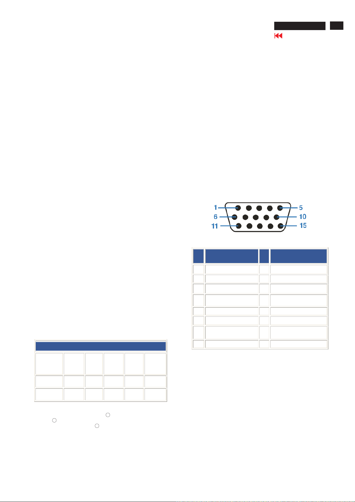
Pin Assignment
The15-pinD-subconnector(male) of the signal cable(IBM systmes):
White Color Temperature
Chromaticity CIE coordinates:
at 9300 degrees K X=0.283/Y=0.297
at 6500 degrees K X=0.313/Y=0.329
at sRGB X=0.313/Y=0.329
Automatic Power Saving
If you have VESA DPMS compliance display card or software
installed in your PC, the monitor can automatically reduce its
power consumption when not in use. If an input from a
keyboard, mouse or other input device is detected, the monitor
will 'wake up' automatically. The following table shows the
power consumption and signaling of this automatic power
saving feature:
Power Management Definition
VESA
Mode
ON Active Yes Yes < 45 W Green
OFF Blanked No No < 1W Amber
Video H-sync V-sync
Power
Used
LED
color
Pin
Assignment
No.
1 Red video input 9 +5V
2 Green video input/SOG 10 Logic ground
3 Blue video input 11 Ground
4 Sense (GND) 12 Serial data line (SDA)
5 Hot Plug Detect 13 H. Sync / H+V
6 Red video ground 14 V. Sy nc (VCLK for DDC)
7 Green video ground 15 Data clock l ine (SCL)
8 Blue video ground
Pin
No.
Assignment
This monitor i s ENERGY STAR R compliant. AsanENERGY
STAR R Partner, PHILIPS has determined that this product
meets the ENERGY STAR R guidelines for energy efficiency
4
107T6 CRT
Go to cover page
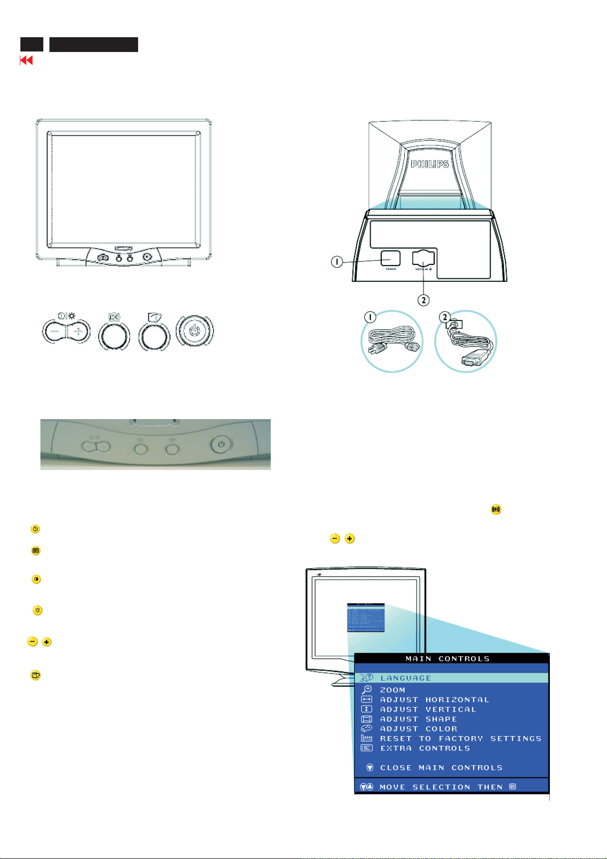
Installation
Front View
Front control
Rear View
1. Power in-attach power cable here.
2. Video In-this is a cable which is already attached to your monitor.
Connect the other end of the cable to your PC.
Power button switches your monitor.
OK button which when pressed will take you to the
OSD controls
Contrast hotkey. When the"-" button is pressed,the adjustment
controls for the CONTRAST will show up.
Brightness hotkey. When the "+" button is pressed,
the adjustment controls for BRIGHTNESS will show up.
"-" and "+" buttons, are used for adjusting the OSD of
your monitor.
LightFrame hotkey. When the button is pressed, the
adjustment controls for LightFrame will show up.
Description of the On Screen Display
What is the On Screen Display?
This is a feature in all philips monitors which allows an end-user to
adjust screen performance of monitors directly through an on screen
instruction on window. The user interface provides user-friendliness and
ease-of-use when operating the monitor.
Basic and simple instruction on the control keys.
On the front controls of your monitor, once you press button, the
On Screen Display (OSD) Main Controls window will pop up and you
can now start making adjustments to your monitor's various features.
Use the buttons to make your adjustments within.
Waring and Notes
107T6 CRT
Go to cover page
5
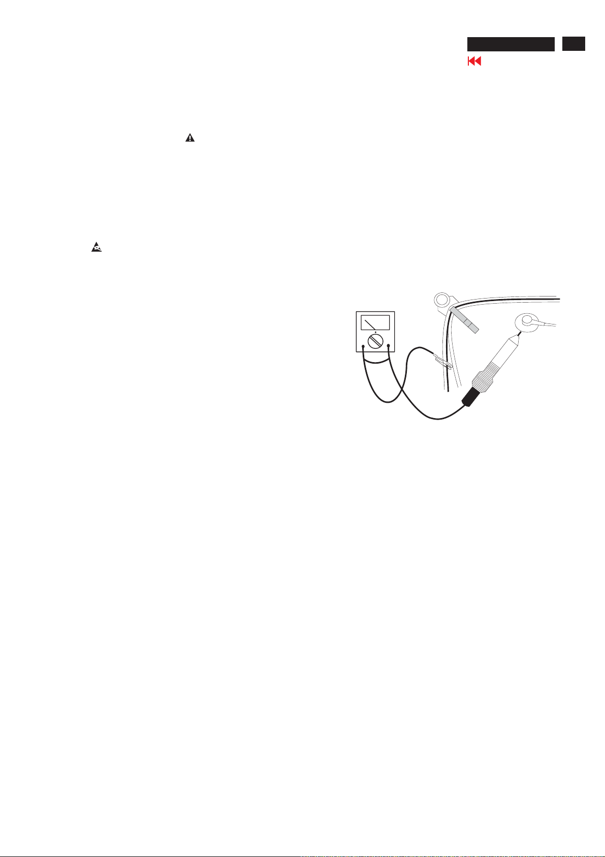
Warnings
1
. Safety regulations require that the unit should be returned
in its original condition and that components identical to
the original components are used. The safety components
are indicated by the symbol .
2
. In order to prevent damage to ICs and transistors, all
high-voltage flash-overs must be avoided. In order to
prevent damage to the picture tube, the method shown
in Fig. 1 should be used to discharge the picture tube.
Use a high-voltage probe and a multimeter (position DC-V).
Discharge until the meter reading is (after approximately
30 seconds).
3 ESD
.
All ICs and many other semiconductors are sensitive to
electrostatic discharges (ESD). Careless handling during
repair can drastically shorten their life. Make sure that
during repair you are connected by a pulse band with
resistance to the same potential as the ground of the unit.
Keep components and tools also at this same potential.
4
. When repairing a unit, always connect it to the AC Power
voltage via an isolating transformer.
5
. Be careful when taking measurements in the high-voltage
section and on the picture tube panel.
0V
Notes
The direct voltages and waveforms are average voltages.
1.
They have been measured using the Service test software
and under the following conditions :
- Mode : 1024*768 (60kHz /75Hz)
- Signal pattern : White pattern
- Adjust brightness and contrast control for the
mechanical mid-position (click position)
The picture tube panel has printed spark gaps.
2.
Each spark gap is connected between an electrode of the
picture tube and the Aquadag coating.
The semiconductors indicated in the circuit diagram(s)
3.
and in the parts lists are completely interchangeable per
position with the semiconductors in the unit, irrespective
of the type indication on these semiconductors.
V
6
. It is recommended that saferty goggles be worn when
replacing the picture tube.
7
. When making adjustments,use plastic rather than metal tools.
This will prevent any short-circuit or the danger of a
circuit becoming unstable.
8
. Never replace modules or other components while the
unit is switched on.
9
. Together with the defleciton unit, the picture tube is used
as an integrated unit. Adjustment of this unit during repair
is not recommended.
10.
After repair, the wiring should be fastened in place with
the cable clamps.
11.
All units that are returned for service or repair must pass
the original manufactures safety tests.
Fig.1

6
107T6 CRT
Go to cover page
The following table lists possible common problems, and the recommended resolution.
Troubleshooting
Having this
problem?
No picture
(Power LED not lit)
No picture
(Power LED is flashing
green)
No picture
(Power LED is green)
Screen doesn't show
when you turn on the
monitor.
No color or intermittent
color
Check these items
Make sure the Power cable is plugged into the power outlet and
back of the monitor.
Power button on the front of your monitor should be in the ON
position.
Disconnect the monitor from the power outlet for about one
minute.
Make sure the computer is turned on.
Make sure the monitor cable is properly connected to your
computer.
Check to see if the monitor cable has bent pins.
The Energy Saving feature may be activated.
Make sure the Brightness and Contrast controls are set correctly.
Make sure the monitor cable is properly connected to your
computer.
Check to see if the monitor cable has bent pins.
Make sure the computer Power button is on.
Make sure the monitor cable is properly connected to your
computer.
Check to see if the monitor cable has bent pins.
Make sure the computer is turned on.
If you are using a non-VESA-DDC standard video card, turn the
DDC1/2B feature Off.
Color appears blotchy
Missing one or more
colors
Dim Picture
Picture is too large
or too small.
Edges of the picture
are not square.
Picture has a double
image.
Picture is not sharp.
The picture may need degaussing.
Remove any nearby magnetic objects.
Face the monitor toward the East for the best picture quality.
Check the Color Temperature.
Make sure the monitor cable is properly connected to your
computer.
Check to see if the monitor cable has ben pins.
Adjust the Brightness and Contrast controls.
Check your video card and it's owner's manual instructions for it
may be a non-VESA-DDC standard card.
Adjust the Horizontal and/or Vertical Size.
Adjust the Zoom.
Adjust the geometry.
Eliminate the use of a video extension cable and/or video switch box.
Face the monitor toward the East for the best picture quality.
Check to make sure Moire is switched off.
Adjust Sync Input.
Unstable Picture.
Increase your refresh rate.
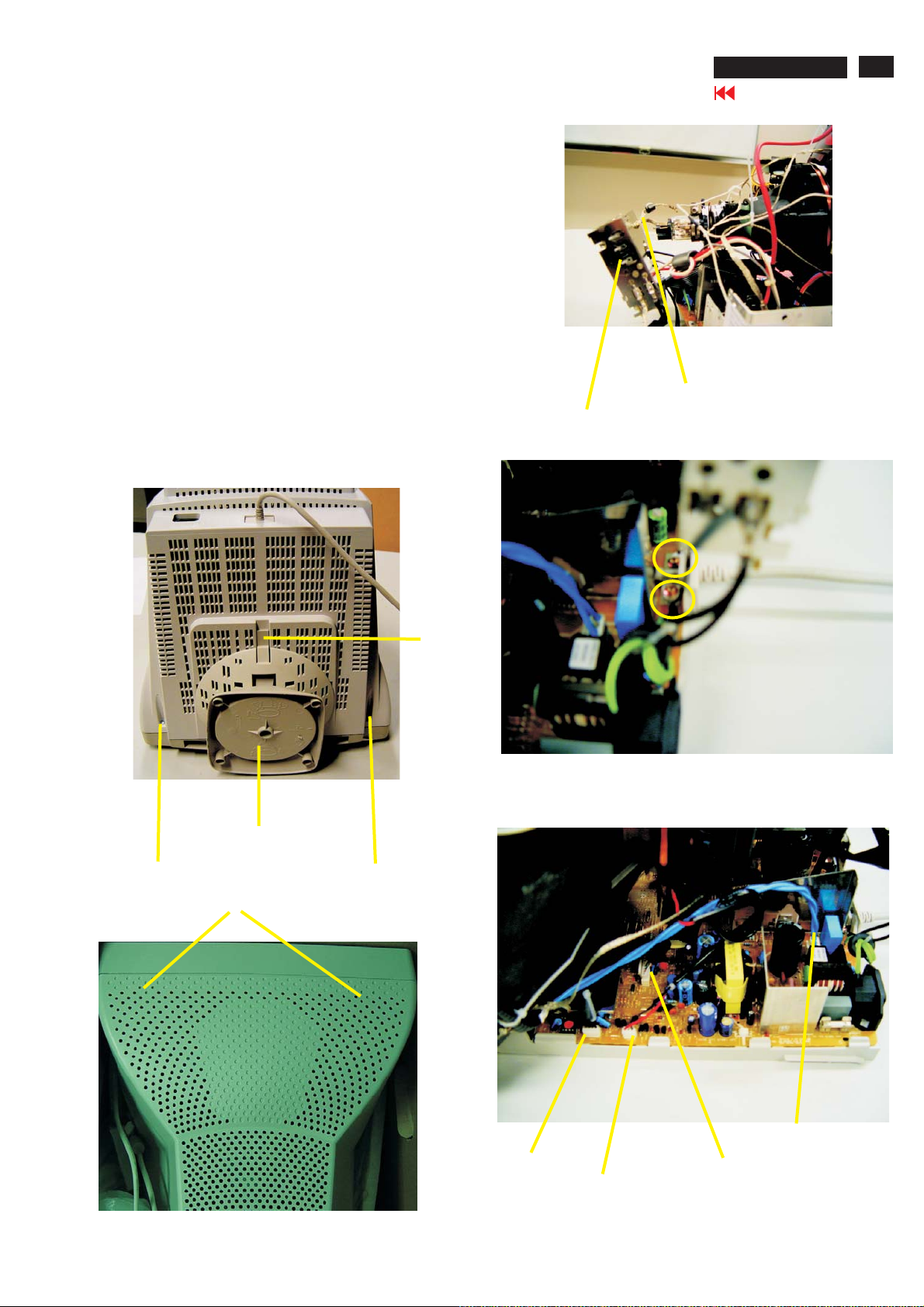
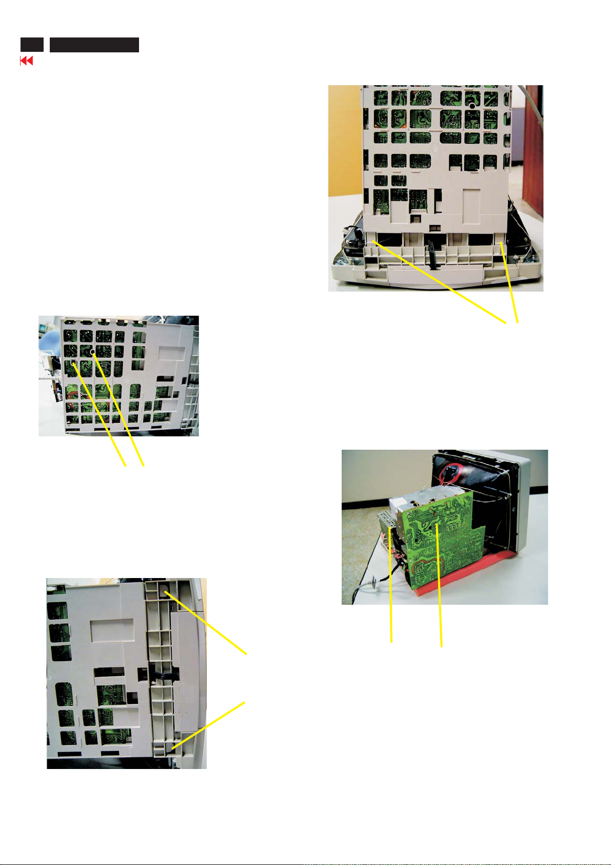
Mechanical Instructions
0. General
To be able to perform measurements and repairs on the "circuit
boards", these unit should placed in the service position first.
1. Remove the rear cover in Fig. 1 and Fig. 2.
-Remove 2 screws as shown
-Remove back cover as shown
-Remove pedestal as shown
2. Video panel
-Disconnect the wire between metal shield of video panel and
CRT neck as shown in Fig. 3.
-Disconnect the CRT grounding from Video panel.
-Remove screw grounding and grounding wire in Fig. 4.
3. Main board connector in Fig. 5.
-Disconnect york wire
-Disconnect rotation connector
-Disconnect control board connector
-Remove Screw for fixed I/F cable
-Remove signal connector
-Remove degaussing wire connector
Video Panel
107T6 CRT
Go to cover page
CRT grounding wire
Fig. 3
7
Screw
Pedestal ass'y
Fig. 1
Clip Press down
Screw
Clip
Screw-grounding
===================>
Fig. 4
Fig. 2
Control connector
Rotation connector
Degaussing wire connector
Signal connector
Fig. 5
8
107T6 CRT
Mechanical Instructions
Go to cover page
4. Main panel with Bottom Tray
-Remove 2 screws for disconnect the Bottom tray as Fig. 6.
-Remove the bottom tray on press right and left side clip from
fig. 7 to fig. 8.
5. SERVICE POSITION
-reconnect connectors, some wires and panels (chassis),
service position can be available for DC/AC measurement
as shown in Fig. 9.
Screw
Fig. 6
Video panel
=======>
Pull-up
Fig. 8
Main panel
Fig. 6
Press clip
Fig. 9 SERVICE POSITION
Electrical Instructions
107T6 CRT
Go to cover page
9
10
107T6 CRT
Go to cover page
Electrical Instructions
CRT
Item
Bias R, G,B Back ground white balan ce 127,135,112 141,121, 136 107,142,115 127,135,112
Gain R, G, B Video white balance 192,169,170 161,171,174202,182,167 192,169,170
*sRGB bright sRGB background brig htness 127127127127
*sRGB contrast sRGB Vid eo b ri ghtn ess 255 255 255 255
* Corner-T,B Top/Bottom corner 185, 155 185, 165 185, 165 175, 155
*PinCorrection-T,B Top/Bottom pincushion 110, 114 127, 115 110, 112 115, 110
* S-wave, S-wav e bal S-wav e, S-wave balance 124, 124 124, 124 124, 124 124, 124
# V-offs et V-ras ter cent er in g 145 145 145 145
# V-gain
* Sub-contrast Sub contrast allowance range 220 220 200 220
* Sub-brightness Sub brightness allowance range 140 200 120 100
#SubH-size
* Lineari ty -H
* Linearity-V Vertical S-correction 110 110 110 110
# Range-UserH User H-size adjustment range 100 100 100 100
# Range-Sub
B+ High voltage adjustment 155 145 140140
ABL Auto brightness adjustment (adjust
Condition/Description LG
DAC value
Fh < 33KHZ
31.5K-70Hz/640x350
31.5K-70Hz/720x400
31.5K-60Hz/640x480
Fh > 33KHz 13060120 80
Sub H-size adj ustment range
Fh < 40KHz
40KHz < Fh < 55KHz 130180130150
55KHz < Fh < 62KHZ 90130 90120
Fh > 62KHz 40754075
Fh < 33KHz 90 100 82 42
33KHz < Fh < 36KHz 105 11590 45
36KHz< Fh < 40KHz 110 128 98 50
40KHz< Fh < 44 KHz 115 130 110 55
44KHz < Fh < 47KHz 122 134 120 58
47KHz< Fh < 51KHz 130138 125 62
51KHZ < Fh < 55KHz 134 142 132 65
55KHz < Fh < 58KHz 136145 13668
58KHz < Fh < 62KHz 140155 142 70
62KHz < Fh < 66KHz 145 160 14672
Fh > 66KHz 150165 152 75
User Zoom adjustment range 145 145 145 145
9300 full white light output)
Fh < 33KHz 120, 60 145, 67 136, 63 144, 6 2EHT com pensation-V, H
33KHz < Fh < 36KHz 110, 65 140, 70 130, 66 134, 66
240
240
130
185 220185 220
189 191133 163
HF
DAC value
150
150
60
CPT
DAC value
220
220
120
SDI
DAC value
180
180
80
Electrical Instructions
107T6 CRT
Go to cover page
11
12
107T6 CRT
OSD Adjustments
Go to cover page
The OSD Controls
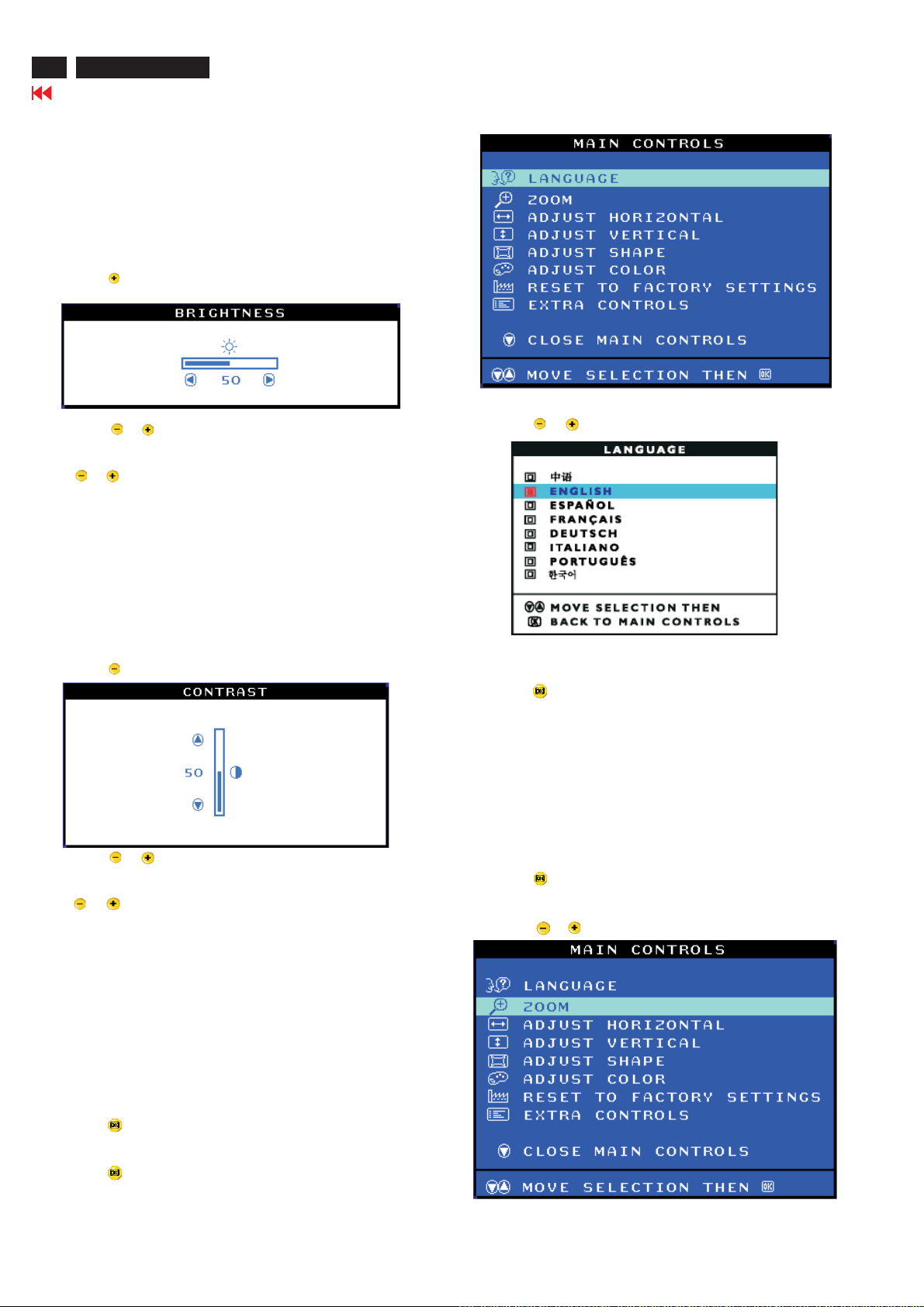
BRIGHTNESS
To adjust your screen's brightness, follow the steps below. Brightness
istheoverallintensityofthelightcomingfromthescreen.A50%
brightness is recommended.
1) Press the button on the monitor. The BRIGHTNESS window
appears.
2) Press the or button to adjust the brightness.
3) When the brightness is adjusted to the level desired. Stop pressing
the or button and after three seconds the BRIGHTNESS
window will disappear with the new adjustment saved.
Smart Help After the BRIGHTNESS window has disappeared, to
continue to the CONTRAST window, follow the steps under CONTRAST.
CONTRAST
To adjust your screen's contrast, follow the steps bellow. Contrast is
thedifferencebetweenthelightanddarkareasonthescreen.A100%
contrast is recommended.
1) Press the button on the monitor. The CONTRAST window appears.
2) Press the or button to adjust the contrast.
3) When the contrast is adjusted to the level desired, stop pressing
the or button and after three seconds the CONTRAST window
will disappear with the new adjustment saved.
3) Press the or button until the desired language is highlighted.
4) pressthe buttontoconfirmyourselectionandreturntoMAIN
CONTROLS window. Close MAIN CONTROLS will be highlighted...
Smart Help After returning to MAIN CONTROLS......to continue to
ZOOM.
ZOOM
ZOOM increase or decrease the size of the images on your screen.
To adjust the ZOOM follow the steps below.
1) Press the button on the monitors. The MAIN CONTROLS
window appears.
2) Press the or button until ZOOM is highlighted.
Smart Help After the CONTRAST window has disappeared, to continue
totheMAINCONTROLS,followthestepsunderLANGUAGE.
LANGUAGE
The ON SCREEN DISPLAY shows its setting in one of eight languages.
The default is English, but you can select French, Spanish, German,
Italian, simplify-Chinese, Korea, Brazilian or Portuguese.
1) Press the button the monitor. The MAIN CONTROLS window
appears. LANGUAGE should be highlighted.
2) Press the button again. The LANGUAGE window appears.
OSD Adjustments (Continued)
107T6 CRT
Go to cover page
13
3) Press the button. The ZOOM window appears.
4) Press the or button to adjust ZOOM.
5) Press the button to confirm your selection and return to the MAIN
CONTROLS window. Close MAIN CONTROLS will be highlighted.
Smart Help After returning to MAIN CONTROLS...
... to continue to ADJUST HORIZONTAL, press the or button until
ADJUST HORIZONTAL is highlighted. Next, follow steps3-7 under ADJUST
HORIZONTAL.
... To exit completely, press the button.
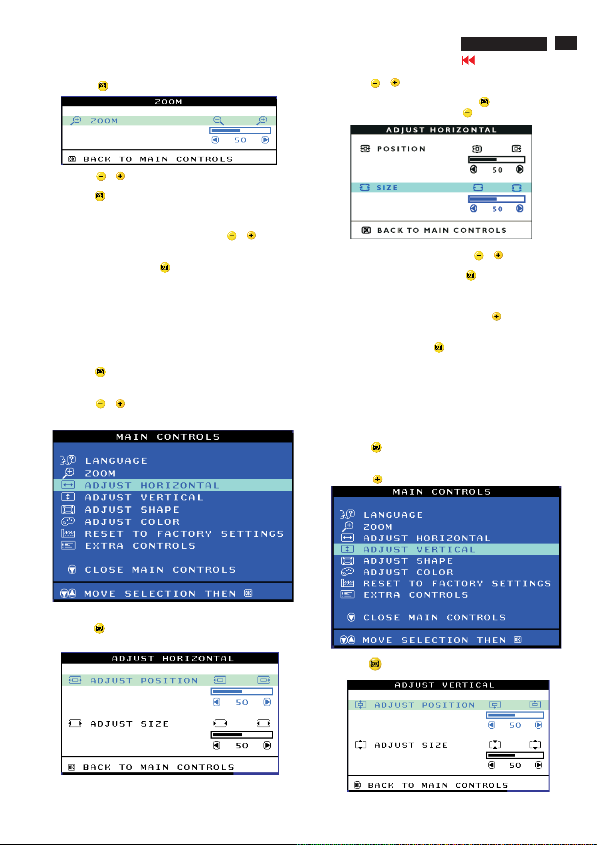
ADJUST HORIZONTAL
ADJUST HORIZONTAL under ADJUST HORIZONTAL shifts the image on
your screen either to the left or right. Use this feature if your image does
not appear centered. ADJUST SIZE under ADJUST HORIZONTAL expands
or controls the image on your screen, pushing it out toward the left and
right sides or pulling it in toward the center.
1) Press the button on the monitor. The MAIN CONTROLS window
appears.
2) Press the or button until ADJUST HORIZONTAL is highlighted.
4) Press the or button to move the image to the left or right.
5) When the position is adjusted, press the button to return to
MAIN CONTROLS window, or press the to highlight ADJUST SIZE.
6) To adjust the horizontal size, press the or button.
7) When the size is adjusted, press the button to return to MAIN
CONTROLS window. CLOSE MAIN CONTROLS will be highlighted.
Smart Help After returning to MAIN CONTROLS...
... To continue to ADJUST VERTICAL, press the button until ADJUST
VERTICAL is highlighted. Next, start with step 3 under ADJUST VERTICAL
and follow the directions.
...To exit completely, press the button.
ADJUST VERTICAL
ADJUST POSITION under ADJUST VERTICAL shifts the image on your
screen either up or down. Use this feature if your image does not
appear centered. ADJUST VERTICAL expands or controls the image on
your screen, pushing it out toward the top or bottom or pulling it in
toward the center.
3) Press the button. The ADJUST HORIZONTAL window appears.
ADJUST POSITION should be highlighted.
1) Press the button on the monitor. The MAIN CONTROLS window
appears.
2) Press the button until ADJUST VERTICAL is highlighted.
3) Press the button. The ADJUST VERTICAL window appears.
ADJUST POSITION should be highlighted.

14
107T6 CRT
OSD Adjustments (Continued)
Go to cover page
4) Pressthe or buttontomovetheimageupordown.
5) When the position is adjusted, press the button to return to
MAIN CONTROLS window, or press the button to highlight
ADJUST SIZE.
6) To adjust the vertical size, press the or button.
7) When the size is adjusted, press the button to return to MAIN
CONTROLS window. CLOSE MAIN CONTROLS will be highlighted.
Smart Help After returning to MAIN CONTROLS...
... To continue to ADJUST SHAPE, press the button until ADJUST
SHAPEishighlighted.Next,startwithstepunderADJUSTSHAPEand
follow the directions.
... To exit completely, press the button.
4) Press the button. The SIDE CURVE window appears.
PINCUSHION should be highlighted.
5) To adjust the pincushion, press the or button, then
pressthe buttontosaveyourselection.
6) When the pincushion is adjusted, press the button to
highlight BALANCE or press the button to return to the
ADJUST SHAPE window.
ADJUST SHAPE
ADJUST SIDE CURVE
ADJUST SIDE CURVE under ADJUST SHAPE allows you to adjust two
of the five preset options. These two options are PINCUSHION and
BALANCED pincushion. Note: use these features only when the picture
is not square.
1) Press the button on the monitor. The MAIN CONTROLS window
appears.
2) Press the button until ADJUST SHAPE is highlighted.
3) Press the button. The ADJUST SHAPE window appears.
ADJUST SIDE CURVE should be highlighted.
7) To adjust the balanced, press the or button.
8) When the balanced is adjusted, press the button. BACK TO
ADJUST SHAPE will be highlighted.
9) Press the button to return to the ADJUST SHAPE window, then
press the button until ADJUST SIDE ANGLES is highlighted.
Smart Help After returning to MAIN CONTROLS...
... To continue to ADJUST SIDE ANGLES, start with step 5 under
ADJUST SIDE ANGLES and follow the directions.
...To exit completely. Press the button twice.
ADJUST SIDE ANGLES
ADJUST SIDE ANGLES under ADJUST SHAPE allows you to adjust
two of the five preset options. These two options are TRAPEZOID
and PARALLELOGRAM. Note: use these features only when the
picture is not square.
1) Press the button on the monitor. The MAIN CONTROLS
window appears.
2) Press the button until ADJUST SHAPE is highlighted.

OSD Adjustments (Continued)
8) To adjust the PARALLELOGRAM, press the or button.
9) When the parallelogram is adjusted, press the button to return
to the ADJUST SHAPE window. BACK TO MAIN CONTROLS window
will be highlighted.
10) Press the button to return to the MAIN CONTROLS window, or
press the button until ROTATE IMAGE is highlighted.
Smart Help After returning to MAIN CONTROLS...
... To continue to ROTATE IMAGE, start with step 5 under ROTATE IMAGE
and follow the directions.
...To exit a completely, press the button twice.
...To adjust only the PARALLELOGRAM, follow steps 1-4 above, then
press the button, and follow steps 7-9
107T6 CRT
Go to cover page
15
3) Press the button. The ADJUST SHAPE window appears.
ADJUST SIDE CURVE should be highlighted.
4) Press the button to highlight ADJUST SIDE ANGLES.
5) Press the button. The SIDE ANGLES window appears.
TRAPEZOID should be highlighted.
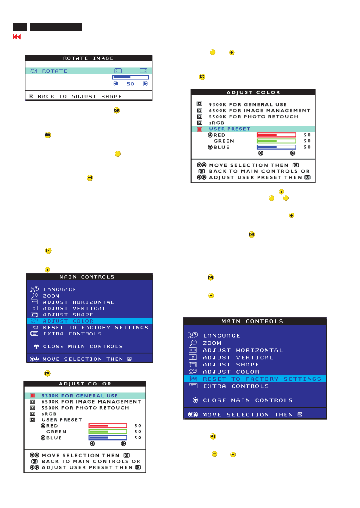
ROTATE IMAGE
ROTATE IMAGE under ADJUST SHAPE allows you to adjust the rotated
image. Note : use this feature only when the picture is not square.
1) Press the button on the monitor. The MAIN CONTROLS window
appears.
2) Press the button until ADJUST SHAPE is highlighted.
6) To adjust the trapezoid, press the or button, then
press the button to save your selection.
7) When the trapezoid is adjusted, press the button to
highlight PARALLELOGRAM or press the button to return
to the ADJUST SHAPE window.
3) Press the button. The ADJUST SHAPE window appears.
ADJUST SIDE CURVE should be highlighted.
4) Press the button until ROTATE IMAGE is highlighted.
5) Press the button. The ROTATE IMAGE window appears.
ROTATE will be highlighted.
6) To adjust the rotation, press the or button.
16
107T6 CRT
OSD Adjustments (Continued)
Go to cover page
7) When the rotation is adjusted, press the button to return to
the ADJUST SHAPE window. BACK TO MAIN CONTROLS should
be highlighted.
8) Press the button to return to MAIN CONTROLS.
Smart Help After returning to MAIN CONTROLS...
... To continue to ADJUST COLOR, press the button until ADJUST
COLOR is highlighted. Next, start with step 3 under ADJUST COLOR
and follow the directions.
... To exit completely, press the button twice.
4) Press the or button to highlight 9300K for GENERAL
USE. 6500K for GAMES, or USER PRESET.
5) Once you have highlighted the GENERAL USE OR GAMES, press
the button to confirm your selection and return to the MAIN
CONTROLS window. CLOSE MAIN CONTROLS will be highlighted.
ADJUST COLOR
Your monitor has two preset options you can choose from. The first
option is for GENERAL USE, which is fine for most applications. The
second option is for GAMES, which is for playing computer games.
When you select one of these options, the monitor automatically
adjusts itself to that option. There is also a third option, USER PRESET,
which allows you to adjust the colors on your screen to a setting you
desire.
1) Press the button on the monitor. The MAIN CONTROLS window
appears.
2) Press the button until ADJUST COLOR is highlighted.
6) If USER PRESET is highlighted, press the button to highlight
RED(GREEN BLUE). Next, press the or button to adjust
the color red(green blue).
7) When all adjustments are complete, press the button until
RESET TO FACTORY SETTINGS is highlighted. Next, start with
step 3 under RESET TO FACTORY SETTINGS.
...To exit completely, press the button.
RESETTOFACTORYSETTINGS
RESETTOFACTORYSETTINGSreturnseverythinginallthewindows
to factory presets.
1) Press the button on the monitor. The MAIN CONTROLS window
appears.
2) Press the button until RESET TO FACTORY SETTING is
highlighted.
3) Press the button. The ADJUST COLOR window appears.
3) Press the button. The RESET TO FACTORY SETTINGS
window appears.
4) Press the or button to select YES or NO. NO is the
defaults. YES return all settings to their original factory
adjustments.
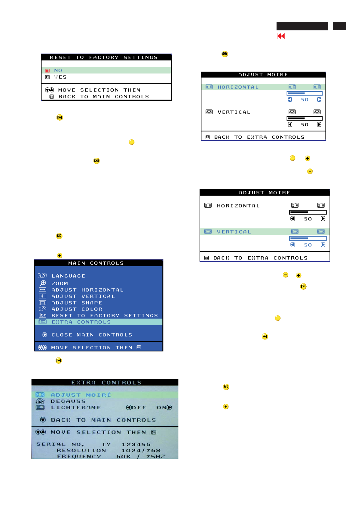
OSD Adjustments (Continued)
5) Press the button to confirm your selection and return to the MAIN
CONTROLS window. CLOSE MAIN CONTROLS will be highlighted.
Smart Help After returning to MAIN CONTROLS...
... To continue to EXTRA CONTROLS, press the button until EXTRA
CONTROLS is highlighted. Next, start with step 3 under EXTRA CONTROLS.
107T6 CRT
Go to cover page
4) Press the button. The ADJUST MOIRE window appears.
HORIZONTAL will be highlighted.
17
...To exit completely, press the button.
EXTRA CONTROLS
ADJUST MOIRE
EXTRA CONTROLS is a set of three feature, including ADJUST MOIRE.
Moire is a fringe patten arising from the interference between two
superimposed line pattens. To adjust your moire, follow the steps below.
Note: use only if necessary. By activating ADJUST MOIRE, sharpness can
be affected.
1) Press the button on the monitor. The MAIN CONTROLS window
appears.
2) Press the button until EXTRA CONTROLS is highlighted.
5) To adjust the horizontal moire, press the or button.
6) When the horizontal moire is adjusted, press the button to
highlight VERTICAL.
7) To adjust the vertical moire, press the or button.
8) When the vertical moire is adjusted, press the button to return
to the EXTRA CONTROLS window. BACK TO MAIN CONTROLS will
be highlighted.
Smart Help After returning to MAIN CONTROLS...
... To continue to DEGAUSS, press the button until DEGAUSS is
highlighted. Next, start with step 3 under EXTRA CONTROLS,
DEGAUSS.
...To exit completely, press the button.
3) Press the button. The EXTRA CONTROLS window appears.
ADJUST MOIRE will be highlighted.
DEGAUSS
EXTRA CONTROLS is a set of three feature, including DEGAUSS.
Degaussing remove electromagnetic build up that may distort the color
on your screen.
1) Press the button on the monitor. The MAIN CONTROLS window
appears.
2) Press the button until EXTRA CONTROLS is highlighted.
18
107T6 CRT
Go to cover page
OSD Adjustments (Continued)
Monitor specific troubleshooting
Self-test Feature Check(STFC)
Your monitor provides a self-test feature that allows you to check
whether your monitor is functioning properly. If your monitor and
computer are properly connected but the monitor screen remains
dark, run the monitor self-test by performing the following steps:
1. Turn off both your computer and the monitor.
2. Unplug the video cable from the back of the computer.
3. Turn on the monitor.
If the monitor is functioning properly, you will see a OSD message
asshowninthefollowingillustration:
3) Press the button. The EXTRA CONTROLS window appears.
ADJUST MOIRE will be highlighted.
4) Press the button until DEGAUSS is highlighted.
5) To degauss your screen, press the button. Your screen will be
degaussed, then the MAIN CONTROLS will reappear. CLOSE MAIN
CONTROLS will be highlighted.
Smart Help After returning to MAIN CONTROLS...
...To exit completely, press the button.
CLOSE MAIN CONTROLS
CHECKSIGNALCABLE
Thisboxalsoappearsduringnormalsystemoperationifthevideo
cable becomes disconnected or damaged. This box will remain on
foroneminute,goofffiveseconds.Thenonforoneminute,andwill
repeat cycle.
1. Turn off your monitor and reconnect the video cable:
then turn on both your computer and the monitor.
2. While in self-test mode, the LED remains green and the pattern
remains on and stationary.
If your monitor screen still remains dark after you use the previous
procedure, check your video controller and computer system; your
monitorisfunctioningproperly.
NO SIGNAL INPUT
If there is something wrong with the input signal, a message appears
on the screen although the power indicator LED is still on. The
message may indicate that the monitor is NO SIGNAL INPUT or that
youneedtocheckthesignalcable.
NO SIGNAL INPUT
OSD Adjustments (Continued)
107T6 CRT
Go to cover page
19
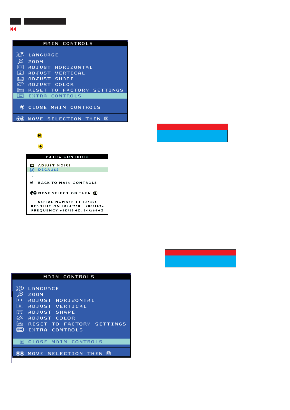
OSD LOCK
OSD LOCK is a feature which disables the OSD controls. It can be used
when the monitor is set up for demonstration purposes or when
adjustment of the OSD is not desirable.
Switch on OSD LOCK feature:
Press and hold the button continuously for 15 seconds.
Release the button when the message
" CONTROL MENU IS LOCKED" appears.
Switch off OSD lock feature:
Press and hold the button continuously for 15 seconds or until
the message window ''CONTROL MENU IS LOCKED''disappears. And
''MAIN CONTROLS'' appears.
To access BURN IN mode
First of all, monitor displays an image.
1. Disconnect the video cable(interface cable).
2. Turn off monitor
3. Press and simultaneously on the front control panel,
then the BURN IN mode comes on the screen of monitor as below.
50 seconds around
5 second around
repeat
4. Reconnect the video cable, then return the normal image.
SERVICE MODE (indication-factory mode)
00050
<-------------------------
00050: stand for
1. Using 10 hours already
2. Turn on/off 10 times.
3. Using several hours
+ turn on/off monitors.
To access factory mode
1. Turn off monitor(don't turn off PC)
2. Press and simultaneously on the front control pane,
then press , wait until the OSD menu with characters
V32 107T6 V0.24 20040303 (below OSD menu) come on the screen
of monitor.
MODEL SELECT
MODEL SELECT
Factory
-----------
-----------
Mode
Indicator
3. If OSD menu disappears on the screen of monitor, press
again(anytime), then the OSD menu comes on the screen again.
4. Using : to select OSD menu.
5. Using : to increase or decrease the setting.
6. Using : to access/confirm the selection.
V32 107T6 V0.24 20040303
V32 107T6 V0.24 20040303
MODEL SELECT
V32 107T6 V0.24 20040303V32 107T6 V0.24 20040303
DefaultsettingofMODELSELECT(Donotchangeit.)
MODEL SELECT
107T6L8
107T6L9
RESERVE
RESERVE
RESERVE
SWDDC
LF 3
To leave factory mode
7. After alignment of factory mode, turn off monitor(if you do not run
off monitor, the OSD menu is always at the factory mode), then turn
on monitor again (at this moment, the OSD menu goes back to user
mode.)
20
RETURN TO TOP OF THE PAGE
107T6 CRT
Go to cover page
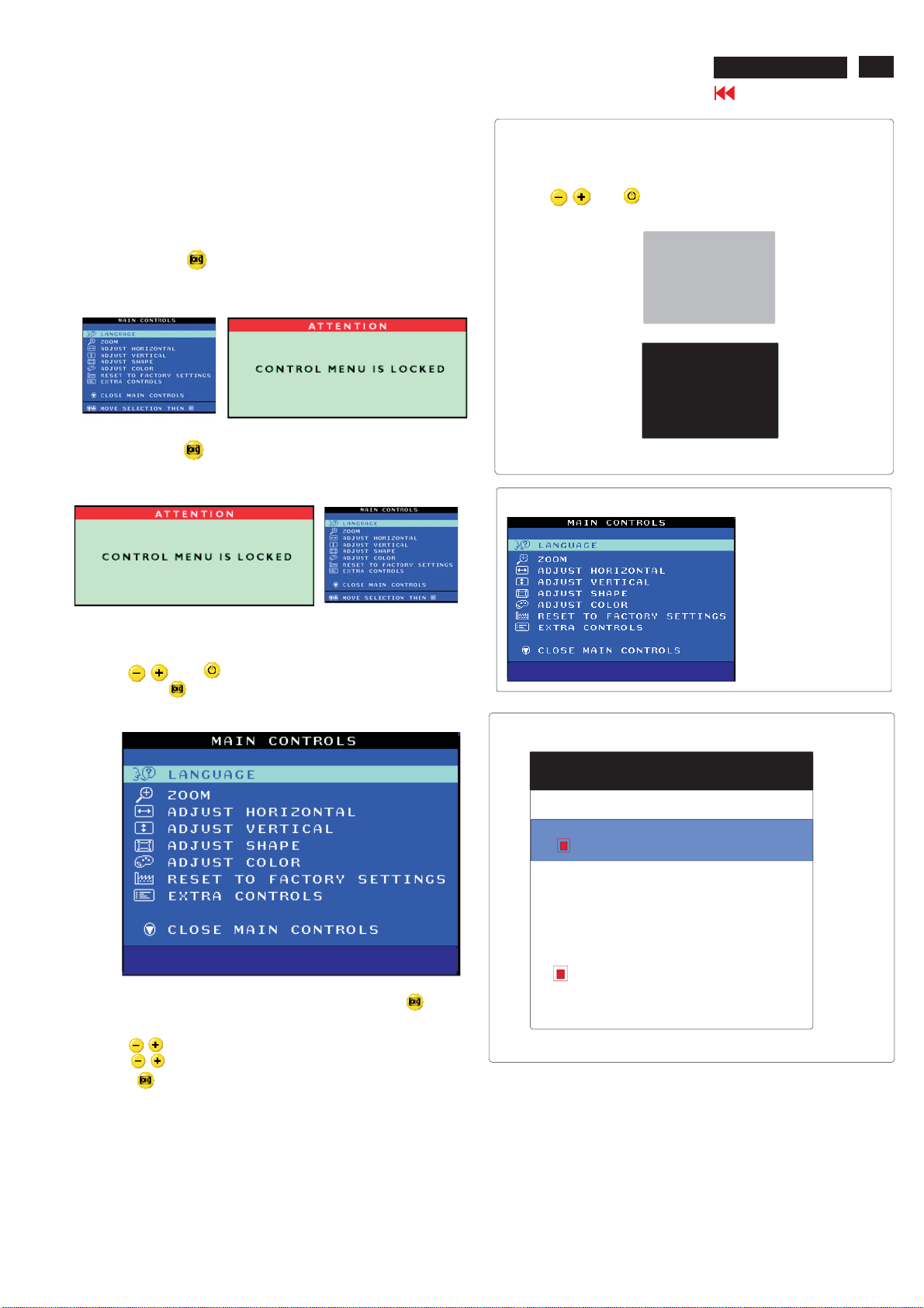
On-Screen Display
OSD Tree
Below is an overall view of the structure of the On-Screen Display. You can use this as reference when you
want to later on work your way around the different adjustments.
Your monitor may not include all the items in the OSD tree shown below.
file:///D|/EDFU/crt_17/edoc/english/OSD_2/OSDDESC.HTM (3 of 3) [2004/5/3 ?? 09:25:56]
ISP (In System Program)
107T6 CRT
Go to cover page
21
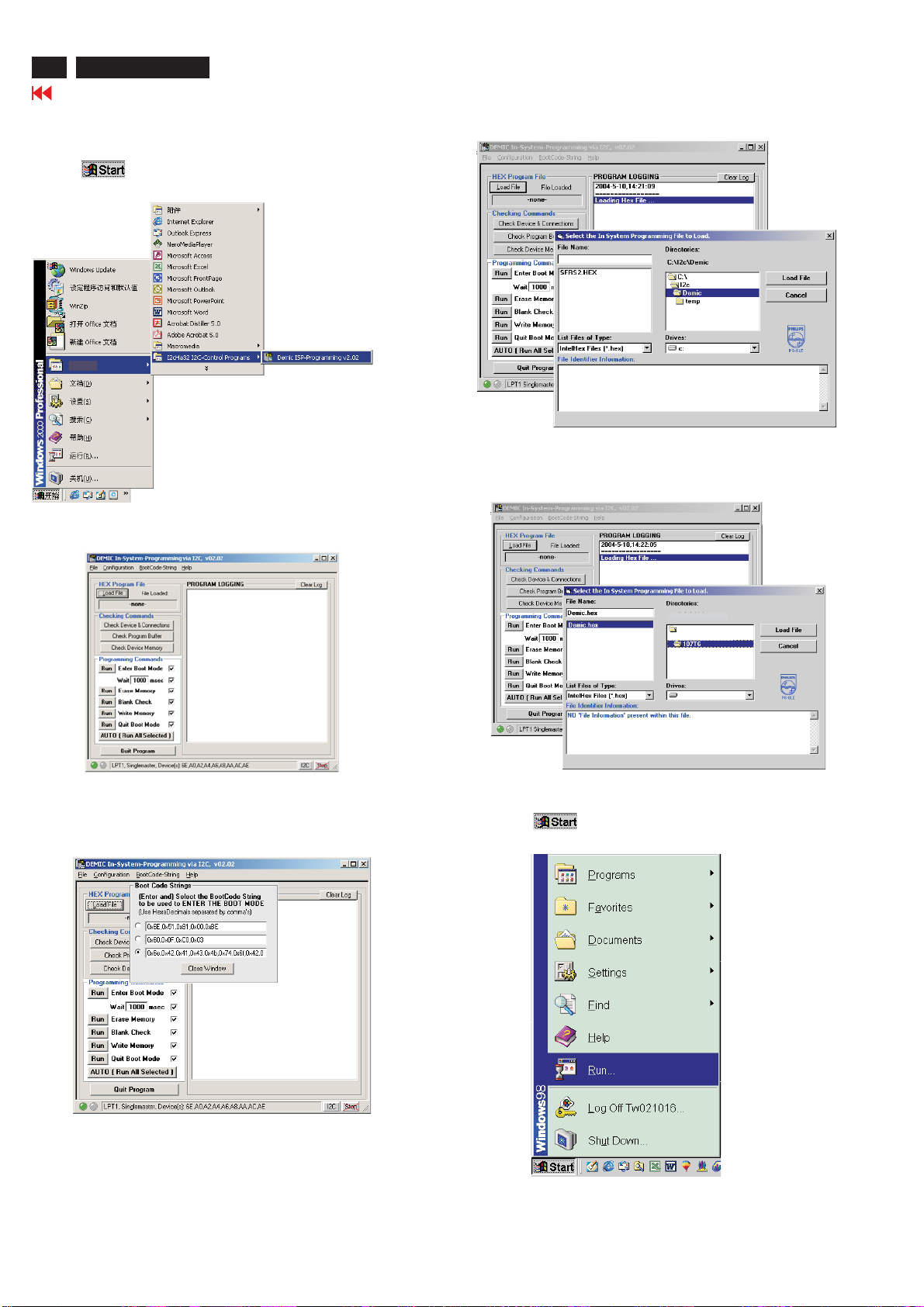
Configuration and Procedure
ISP (In System Program) software is provided to upgrade the
firmware of CPU.
System and equipment requirement:
1. An i486 (or above) personal computer or compatible.
2. Microsoft operation system windows 95/98.
3. EDID 46.EXE program (12NC: 3138 106 10103) and ISP Software
(12NC:3138 106 10375) (Provided in the CD-ROM SERVICE MANUAL)
4. Software DDC Alignment kits(3138 106 10079) shown as Fig. 1.
The kit contents: a. Alignment box X 1
b. Printer cable X 1
c. (D-sub) to (D-sub) cable X 1
d. (DVI-D) TO (D-sub) cable X 1
Fig. 1
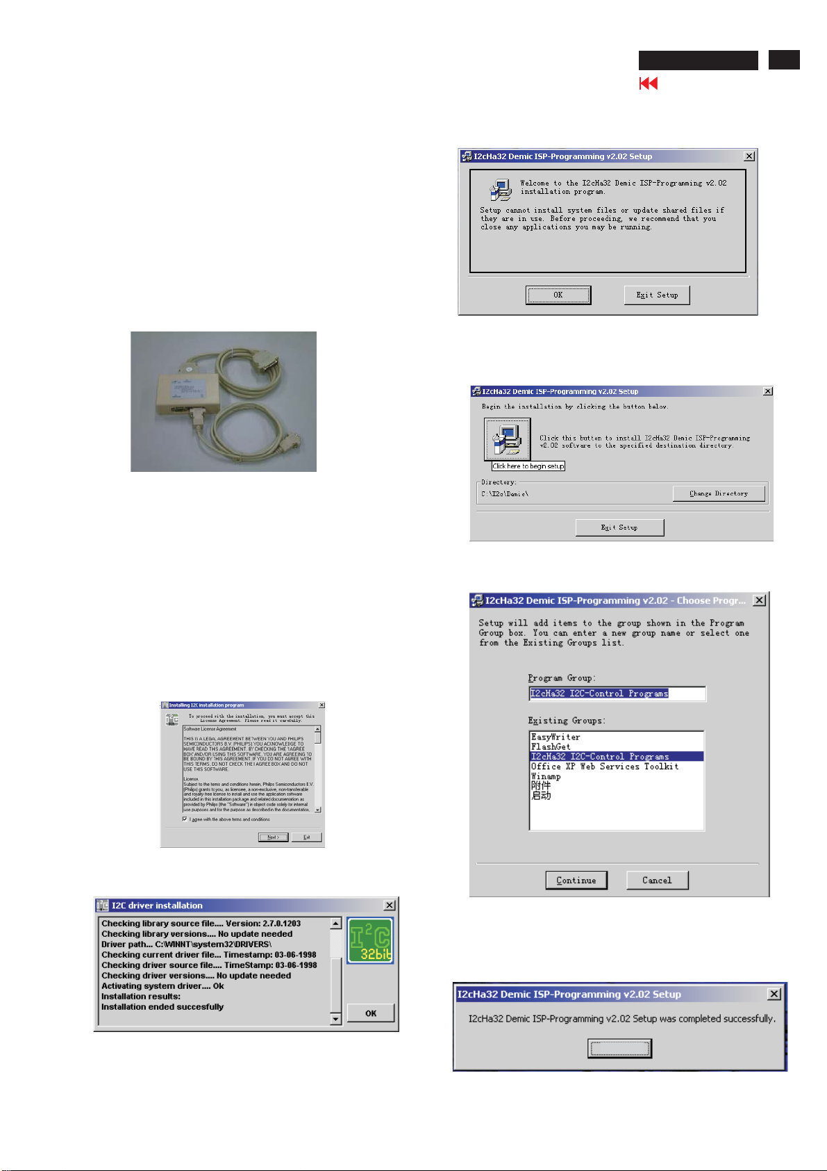
Step 1. Installation of ISP Software
4. Execute the "Setup.exe" of the 107T6 folder to install execution file.
1) Bring up the window as shown in Fig. 4, click "OK".
Fig. 4
2) Bring up the window as shown in Fig. 5, click the icon of the left
side of the window to begin setup.
1. Make a folder in your computer as shown in Fig. 2. For example
C:\107T6
2. Copy ISP Software(ISP.zip 12NC: 3138 106 10375) , EDID program
(edid 46.exe 12NC:3138 106 10103) and Demic Code (Demic.hex)
from the CD-ROM to C:\107T6.
3. Unzip the ISP.zip, and execute the ''I2cHa32-Driver.exe" to install
driver.
1) Bring up the window as shown in Fig. 2, click "I agree with the
above terms and conditions", then click "next".
Fig. 2
2) Bring up the window as shown in Fig. 3, click "OK", which means
you have already installed I2Cdriver successfully.
Fig. 5
3) Bring up the window as shown in Fig. 6, click"continue".
Fig. 6
4) Bring up the window as shown in Fig. 7, which means you have
setup the ISP-Programming successfully, click "ENTER" to confirm
it.
Fig. 3
ENTER
Fig. 7
22
107T6 CRT
ISP (In System Program)
Go to cover page
Step 2. Load Hex file and input the bootcode.
1. Click , choose programs at start menu of Windows95/98 ,
find I2cHaI2c-Control Programs as shown in Fig. 8.
Programms
Fig. 8
2. Click the ''I2cHaI2c-Control Programs'',bring up the below
window as shown in Fig. 9.
Fig. 9
3. Click Bootcode-string, choose the third row and input the
following codes ''0x6e, 0x42, 0x41, 0x43, 0x4b, 4x74, 0x6f,
0x42, 0x4f, 0x4f, 0x54'', then click ''close window''.
(Fig. 10)
Fig. 11
5. Choose the Demic. Hex from C:\107T6, the left side of the window
will show the file name"Demic.hex", click "Demic.hex" of the left
sideofthewindow,thenclick"Loadfile",shownasFig.12.
C:\107T6
C:\
C:
Fig. 12
Step 3. Run EDID46 program.
1. Click , choose Run at start menu of Windows95/98 as
shown in Fig. 13.
Fig. 10
4. Click''loadfile'',bringupthefollowingwindowasshowninFig11.
Fig. 13
ISP (In System Program)
107T6 CRT
Go to cover page
23
2. At the submenu, type the path of EDID46
(For example, C:\107T6\EDID46.exe, as shown in Fig. 14).
C:\107T6\edid46.exe
Fig. 14
3. Click button. The main menu appears (as shown in Fig. 15).OK
This is for initialize alignment box.
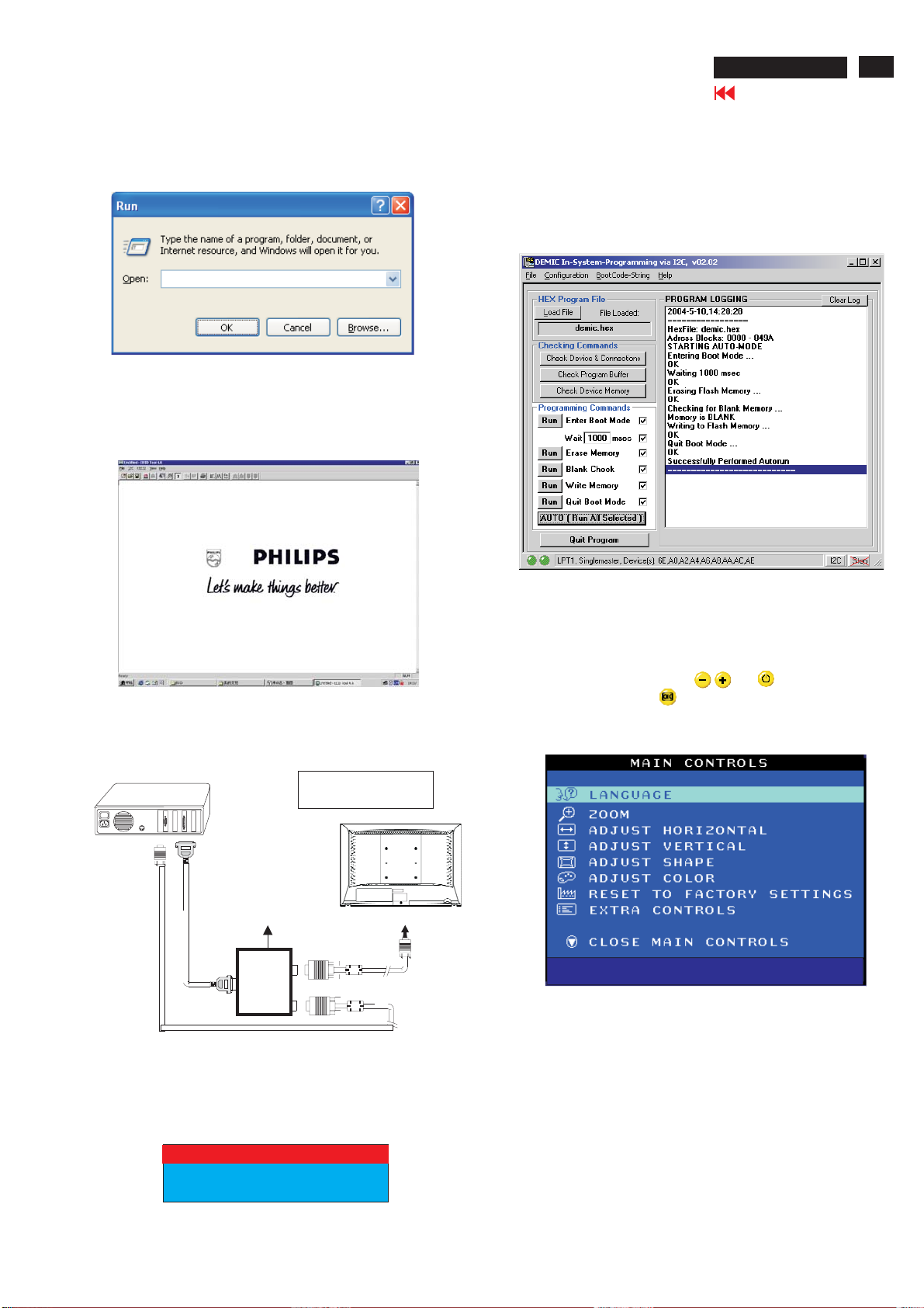
Step 5: Upgrade the firmware
Choose all the items of the Programming commands, then click
"AUTO(RunAll Selected)",thesoftwarewillupgradethefirmware,
the LED will extinguish several seconds, after finished the upgrade,
the monitor will stand-up automatically. Bring up the window as
showninFig.18,whichmeansyouhavefinishedtheupgrade
successfully.
Fig. 15
Step 4. Connecting all cables and box as shown in Fig. 16.
PC
1
Note: Before you connect all the cables and box, you must
execute EDID46.exe (substeps 5 to 7) firstly, otherwise, after you
connected the alignment kits, the following warning message will
appearonthescreenasshowninFig.17.
DC Power
8-12V
To printer port (LTP1)
Printer
Port
To PC Video Port (D-sub)
1=Power connector
2=D-SUB connector
~
~
To
Monitor
To P C
Fig. 16
1
2
----->
----->
Fig. 18
Click"Quit Program", quit the program.
Turn off the monitor, then press and simultaneously till
the LED light, then press button, bring up MAIN CONTROLS.
You will find, after upgrade, the version have already changed
from the former"V32 107T6 V0.24 20040303" to the present
"V32 FAMILY V2.00 20040427".
MODEL SELECT
MODEL SELECT
Factory
Mode------------Indicator
Turn off the monitor to exit the factory mode.
V32 107T6 V0.24 20040303
V32 FAMILY V2.00 20040427
, shown in Fig. 19.
Fig. 19
CHECKSIGNALCABLE
Fig. 17
24
Lenovo CK5S5
DDC Instructions
Go to cover page
General
DDC Data Re-programming
In case the DDC data memory IC or main EEPROM which storage all
factory settings were replaced due to a defect, the serial numbers have
to be re-programmed" ".
It is advised to re-soldered DDC IC and main EEPROM from the old
board onto the new board if circuit board have been replaced, in this
case the DDC data does not need to be re-programmed.
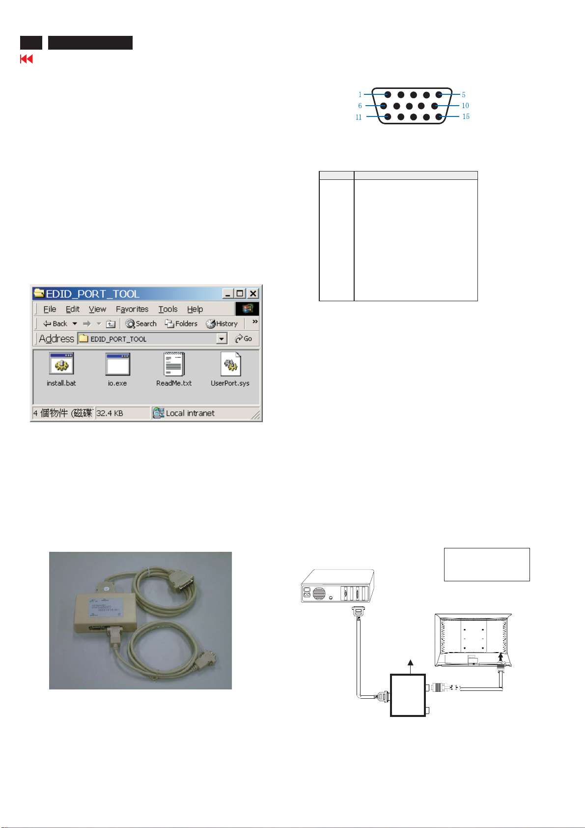
Analog DDC IC, & EEPROM
Pin assignment
15-pin D-Sub Connector
Additional information
Additional information about DDC (Display Data Channel) may be
obtained from Video Electronics Standards Association (VESA). Extended
Display Identification Data(EDID) information may be also obtained from
VESA.
System and equipment requirements
1. An i486 (or above) personal computer or compatible.
2. Microsoft operation system Windows 95/98 .
Y o Install the EDID_PORT_Tool under Win2000/XP . As
ou have t
Fig. 1 .
A. Cody the "UserPort.sys" to C:\WINNT\system32\drivers(win2000)
C:\WINDOWS\system32\drivers(winXP)
B. Running " io.exe" everytime, Before you start to programming
edid data .
3. EDID46.EXE program (12NC: 3138 106 10103) .
4. A/D Alignment kits (12NC: 3138 106 10079) shown as Fig. 2:
inclusion : a. Alignment box x1
Fig. 1Fig. 1
PIN No. SIGNAL
1 Red vi deo input
2 Green video input / sync on green
3 Blue video input
4 GND
5 GND -Cable detect
6 Red vi deo GND
7 Green video GND
8 Blue video GND
9 DDC +3.3V or +5V
10 Logic GND
11 GND
12 Serial data line (SDA)
13 H-sync / H+V
14 V-sync
15 Data clock line (SCL)
Configuration and procedure
There is no Hardware DDC (DDC IC) anymore. Main EEPROM stores
all factory settings and DDC data (EDID code) which is also called
Software DDC. The following section describes the connection and
procedure for Software DDC application. The main EEPROM can be reprogrammed by enabling '' factory memory data write'' function on the
DDC program (EDID46.EXE).
Initialize alignment box
In order to avoid that monitor entering power saving mode due
to sync will cut off by alignment box, it is necessary to initialize
alignment box before running programming software
(EDID46.EXE). Following steps show you the procedures and
connection.
Step 1: Supply 8-12V DC power source to the Alignment box by
plugging a DC power cord .
Step 2: Connecting printer cable and D-Sub cable of monitor as Fig. 3
PC
1=Power connector
2=D-SUB connector
Fig. 2
b. Printer cable x1
c. (D-Sub) to (D-Sub) cable x1
D. (DVI-D) to (D-Sub) cable x1
Note: The EDID46.EXE is a windows-based program, which cannot
be run in MS-DOS.
TP1)
L
To printer port (
DC Power
8-12 V
~
~
To
Monitor
Printer
Port
To P C
----->
1
Fig. 3
----->
2
DDC Instructions (Continued)
107T6 CRT
Go to cover page
25
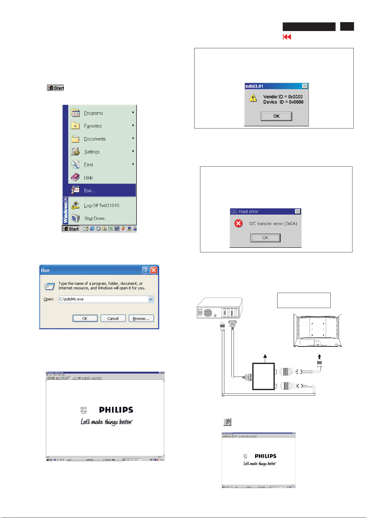
Step 3: Installation of EDID46.EXE
Method 1: Start on DDC program
Start Microsoft Windows.
1. The Program"EDID46.EXE" in service manual cd-rom be copyed to C:\ .
2. Click , choose Run at start menu of Windows as shown
In Fig. 4.
Fig. 4
Note 1: If the connection is improper, you will see the following error
message (as shown in Fig. 7) before entering the main menu.
Meanwhile, the (read EDID) function will be disable. At this
time, please make sure all cables are connected correctly and
fixedly, and the procedure has been performed properly.
Fig. 7
Note 2: During the loading, EDID46 will verify the EDID data which just
loaded from monitor before proceed any further function, once
the data structure of EDID can not be recognized, the following
error message will appear on the screen as below. Please
confirm following steps to avoid this message.
1. The data structure of EDID was incorrect.
2. DDC IC that you are trying to load data is empty.
3. Wrong communication channel has set at configuration setup
windows.
4. Cables loosed or poor contact of connection.
3. At the submenu, type the letter of your computer's hard disk drive
followed by :EDID46 (for example, C:\EDID46, as shown in Fig. 5).
1
Fig. 5
4. Click button. The main menu appears (as shown in Fig. 6).OK
This is for initialize alignment box.
Fig. 8
Re-programming EEPROM(Software DDC IC)
Step 1: After initialize alignment box, connecting all cables and
box as shown in Fig. 9
PC
DC Power
8-12V
To printer port (LTP1)
Printer
Port
To PC Video port (D-sub)
Step 2: Read DDC data from monitor
1=Power connector
2=D-SUB connector
~
~
To
Monitor
To P C
1
2
----->
----->
Fig. 9
Fig. 6
1. Click icon as shown in Fig. 10 from the tool bar to bring up
the Channels "Configuration Setup" windows as shown in Fig. 11.
Fig. 10
26
107T6 CRT
DDC Instructions (Continued)
Go to cover page
2. Select the DDC2Bi as the communication channel.
As shown in Fig. 11.
Fig. 11
3. Click OK button to confirm your selection.
4. Click icon (Read EDID function) to read DDC EDID data from
monitor. The EDID codes will display on screen as shown in Fig. 12.
Fig. 14
2. Click , bring up Fig. 15.Next
Don't close this screen. --->
Fig. 12
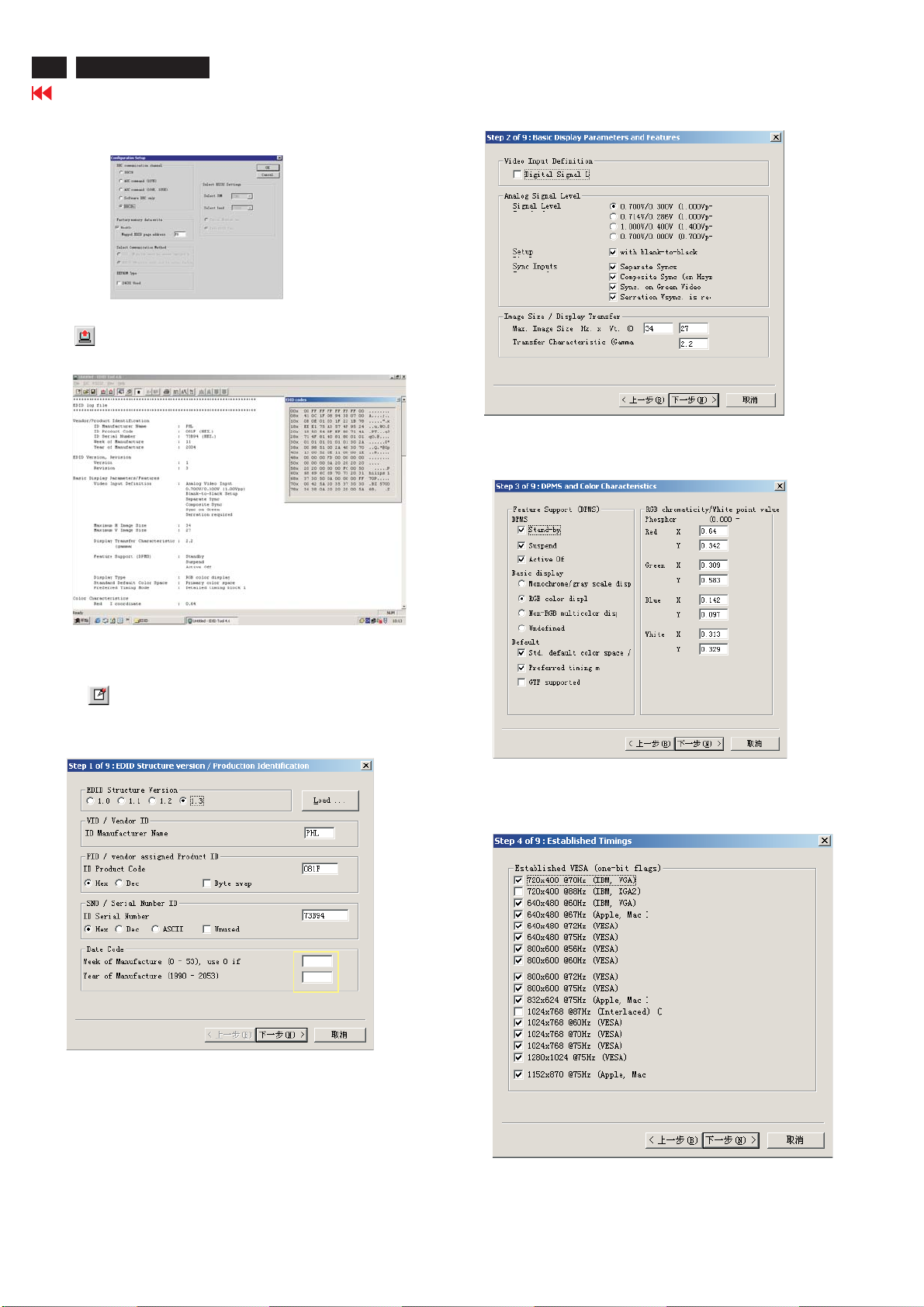
Step 3: Modify DDC data (verify EDID version, week, year)
1. Click (new function) icon from the tool bar, bring up
Step 1 of 9 as shown in Fig. 13 .
EDID46 DDC application provides the function selection and
text change (select & fill out) from Step 1 to Step 9.
To Printer port
DC 8~12V
To Monitor
D-sub/DVI cable
5
2003
Select and fill out,
If necessary.
Fig. 15
3. Click , bring up Fig. 16.Next
Fig. 13
Step 4: Modify DDC data (Monitor Serial No.)
Next1. Click , bring up Fig. 14.
Fig. 16
DDC Instructions (Continued)
107T6 CRT
Go to cover page
27
4. Click , bring up Fig. 17.Next
5. Click , bring up Fig. 18.Next
Fig. 17
7. Click , bring up Fig. 20.Next
107T4
Fig. 20
8. Click , bring up Fig. 21.Next
- Click Finish to exit the Step window.
9
8. Click , bring up Fig. 19.Next
Fig. 18
- Serial number can be filled up at this moment (for example,
TY 000812).
TY 000812
Fig. 21
Step 5: Write DDC data
1. Configuration should be as Fig. 22. And press OK.
Fig. 22
Fig. 19
28
107T6 CRT
Go to cover page
DDC Instructions (Continued)
2. Access Factory Mode
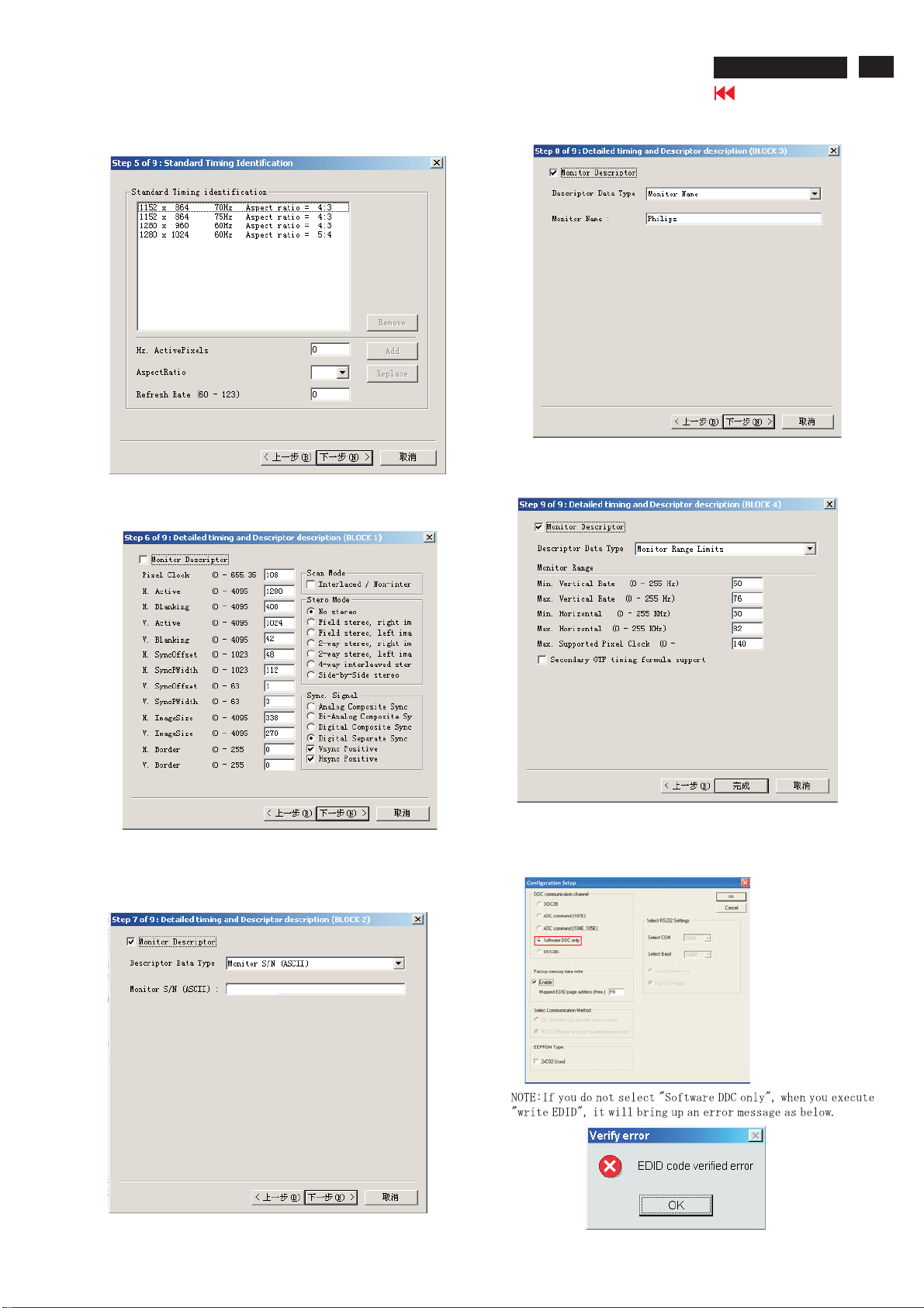
1). Turn off monitor.
2). [Push " " & " " buttons at the same time and hold it
]+[Presspower" "buttonuntillcomesout"Windowsscreen"]
=>thenreleaseallbutton,thenpress ,waituntiltheOSDmenu
with
Characters V32 107T6 V0.24 20040303 (below OSD menu) come on
the Screen of the monitor (see Fig. 23).
MODEL SELECT
MODEL SELECT
Factory
Mode------------Indicator
3. Click (Write EDID) icon from the tool bar to write DDC data.
Bring up " ready" a progressing bar on the left, then bring up the
Window as shown in Fig.24, click the " enter" button to finish Writing
V32 107T6 V0.24 20040303
V32 107T6 V0.24 20040303
Fig. 23
Step 6: Save DDC data
Sometimes, you may need to save DDC data as a text file for using
in other IC chip. To save DDC data, follow the steps below:
1. Click (Save) icon (or click "file"-> "save as") from the tool bar
And give a file name as shown in Fig. 25.
The file type is EDID46 file (*.ddc) which can be open in WordPad.
By using WordPad, the texts of DDC data & table (128 bytes, hex
code) can be modified. If DDC TEXTS & HEX Table are completely
correct, it can be saved as .ddc flie to re-load it into DDC IC for DDC
Data application.
107T6
107T6-DDC
107T6-DDC
Fig. 25
2. Click .Save
Step 7: Exit DDC program
Pull down the File menu and select Exit as shown in Fig. 26.
ENTER
4. Confirm Serial Number in User Mode
1) Press the button to turn off the monitor. Press the button
again to turn on the monitor.
2) Press the button to bring up the OSD main menu.
3) Press the button to select Extra Controls, press the button to
confirm your selection.
4) Confirm the Serial Number ''TY 000812'' is updated as shown in
Fig. 25.
Fig.24
000812
Fig. 26

HEX Data of DDC2B
107T6 CRT
Go to cover page
29
****************************************************
****************************************************
Vendor/Product Identification
ID Manufacturer Name : PHL
ID Product Code : E01C (HEX.)
ID Serial Number : 1E240 (HEX.)
Week of Manufacture : 19
Year of Manufacture : 2004
EDID Version, Revision
Version : 1
Revision : 3
Basic Display Parameters/Features
Video Input Definition : Analog Video Input
Maximum H Image Size : 31
Maximum V Image Size : 23
Display Transfer Characteristic: 2.68
(gamma)
Feature Support (DPMS) : No Standby
Display Type : RGB color display
Color Characteristics
Red X coordinate : 0.625
Red Y coordinate : 0.336
Green X coordinate : 0.29
Green Y coordinate : 0.599
Blue X coordinate : 0.145
Blue Y coordinate : 0.149
White X coordinate : 0.283
White Y coordinate : 0.297
Established Timings
Established Timings I : 720 x 400 @70Hz (IBM,VGA)
Established Timings II : 800 x 600 @72Hz (VESA)
Manufacturer's timings :
Standard Timing Identification #1
Horizontal active pixels : 640
Aspect Ratio : 4:3
Refresh Rate : 85
Standard Timing Identification #2
Horizontal active pixels : 800
Aspect Ratio : 4:3
Refresh Rate : 85
Standard Timing Identification #3
Horizontal active pixels : 1024
Aspect Ratio : 4:3
Refresh Rate : 85
Standard Timing Identification #4
Horizontal active pixels : 1280
Aspect Ratio : 5:4
Refresh Rate : 60
Standard Timing Identification #5
Horizontal active pixels : 640
Aspect Ratio : 4:3
Refresh Rate : 100
EDID log file for LG tube
0.700V/0.000V (0.70Vpp)
without Blank-to-Black Setup
Separate Sync
Without Composite Sync
WithoutSynconGreen
no Serration required
No Suspend
Active Off
640 x 480 @60Hz (IBM,VGA)
640 x 480 @72Hz (VESA)
640X 480 @ 75Hz (VESA)
800x 600 @60Hz (VESA)
800 X 600 @75Hz (VESA)
832 X 624 @75 Hz (Apple, MacII)
1024 x 768 @60Hz (VESA)
1024 x 768 @70Hz (VESA)
1024 X768 @75Hz (VESA)
**********************************************************************
EDID data (128 bytes) for LG tube
**********************************************************************
0: 00 1: ff 2: ff 3: ff 4: ff 5: ff 6: ff 7: 00
8: 41 9: 0c 10: 1c 11: e0 12: 40 13: e2 14: 01 15: 00
16: 13 17: 0e 18: 01 19: 03 20: 68 21: 1f 22: 17 23: a8
24: 28 25: 05 26: 78 27: a0 28: 56 29: 4a 30: 99 31: 26
32: 12 33: 48 34: 4c 35: ad 36: ee 37: 00 38: 31 39: 59
40: 45 41: 59 42: 61 43: 59 44: 81 45: 80 46: 31 47: 68
48: 45 49: 68 50: 81 51: 40 52: 71 53: 4f 54: d6 55: 09
56: 80 57: a0 58: 20 59: 5e 60: 63 61: 10 62: 10 63: 60
64: 52 65: 08 66: 32 67: e6 68: 10 69: 00 70: 00 71: 1a
72: 00 73: 00 74: 00 75: ff 76: 00 77: 20 78: 42 79: 5a
80: 20 81: 20 82: 31 83: 32 84: 33 85: 34 86: 35 87: 36
88: 0a 89: 20 90: 00 91: 00 92: 00 93: fc 94: 00 95: 50
96: 48 97: 31 98: 30 99: 37 100: 43 101: 2f 102: 46 103: 2f
104: 48 105: 2f 106: 54 107: 36 108: 00 109: 00 110: 00 111: fd
112: 00 113: 32 114: a0 115: 1e 116: 47 117: 0c 118: 00 119: 0a
120: 20 121: 20 122: 20 123: 20 124: 20 125: 20 126: 00 127: 2c
Standard Timing Identification #6
Horizontal active pixels : 800
Aspect Ratio : 4:3
Refresh Rate : 100
Standard Timing Identification #7
Horizontal active pixels : 1280
Aspect Ratio : 4:3
Refresh Rate : 60
Standard Timing Identification #8
Horizontal active pixels : 1152
Aspect Ratio : 4:3
Refresh Rate : 75
Detailed Timing #1
Pixel Clock (MHz) : 25.18
H Active (pixels) : 640
H Blanking (pixels) : 160
V Active (lines) : 350
V Blanking (lines) : 99
H Sync Offset (F Porch) (pixels): 16
H Sync Pulse Width (pixels): 96
V Sync Offset (F Porch) (lines) : 37
V Sync Pulse Width (lines) : 2
HImageSize(mm) : 306
VImageSize(mm) : 230
HBorder(pixels) : 0
VBorder(lines) : 0
Flags : Non-interlaced
: Normal Display, No stereo
: Digital Separate sync.
: Negative Vertical Sync.
: Positive Horizontal Sync.
Monitor Descriptor #2
Serial Number : BZ 123456
Monitor Descriptor #3
Monitor Name : PH107C/F/H/T6
Monitor Descriptor #4
Monitor Range Limits
Min.VtrateHz : 50
Max. Vt rate Hz : 160
Min.Horiz.ratekHz : 30
Max. Horiz. rate kHz : 71
Max. Supported Pixel : 120
No secondary GTF timing formula supported.
Extension Flag : 0
Check sum : 2C (HEX.)

30
107T6 CRT
Go to cover page
HEX Data of DDC2B
****************************************************
****************************************************
Vendor/Product Identification
ID Manufacturer Name : PHL
ID Product Code : E01C (HEX.)
ID Serial Number : 1E240 (HEX.)
Week of Manufacture : 19
Year of Manufacture : 2004
EDID Version, Revision
Version : 1
Revision : 3
Basic Display Parameters/Features
Video Input Definition : Analog Video Input
Maximum H Image Size : 31
Maximum V Image Size : 23
Display Transfer Characteristic: 2.8
(gamma)
Feature Support (DPMS) : No Standby
Display Type : RGB color display
Color Characteristics
Red X coordinate : 0.62
Red Y coordinate : 0.35
Green X coordinate : 0.29
Green Y coordinate : 0.61
Blue X coordinate : 0.15
Blue Y coordinate : 0.065
White X coordinate : 0.283
White Y coordinate : 0.297
Established Timings
Established Timings I : 720 x 400 @70Hz (IBM,VGA)
Established Timings II : 800 x 600 @72Hz (VESA)
Manufacturer's timings :
Standard Timing Identification #1
Horizontal active pixels : 640
Aspect Ratio : 4:3
Refresh Rate : 85
Standard Timing Identification #2
Horizontal active pixels : 800
Aspect Ratio : 4:3
Refresh Rate : 85
Standard Timing Identification #3
Horizontal active pixels : 1024
Aspect Ratio : 4:3
Refresh Rate : 85
Standard Timing Identification #4
Horizontal active pixels : 1280
Aspect Ratio : 5:4
Refresh Rate : 60
Standard Timing Identification #5
Horizontal active pixels : 640
Aspect Ratio : 4:3
Refresh Rate : 100
EDID log file for HF tube
0.700V/0.000V (0.70Vpp)
without Blank-to-Black Setup
Separate Sync
Without Composite Sync
WithoutSynconGreen
no Serration required
No Suspend
Active Off
640 x 480 @60Hz (IBM,VGA)
640 x 480 @72Hz (VESA)
640X 480 @ 75Hz (VESA)
800x 600 @60Hz (VESA)
800 X 600 @75Hz (VESA)
832 X 624 @75 Hz (Apple, MacII)
1024 x 768 @60Hz (VESA)
1024 x 768 @70Hz (VESA)
1024 X768 @75Hz (VESA)
**********************************************************************
EDID data (128 bytes) for HF tube
**********************************************************************
0: 00 1: ff 2: ff 3: ff 4: ff 5: ff 6: ff 7: 00
8: 41 9: 0c 10: 1c 11: e0 12: 40 13: e2 14: 01 15: 00
16: 13 17: 0e 18: 01 19: 03 20: 68 21: 1f 22: 17 23: b4
24: 28 25: e5 26: b8 27: 9e 28: 59 29: 4a 30: 9c 31: 26
32: 10 33: 48 34: 4c 35: ad 36: ee 37: 00 38: 31 39: 59
40: 45 41: 59 42: 61 43: 59 44: 81 45: 80 46: 31 47: 68
48: 45 49: 68 50: 81 51: 40 52: 71 53: 4f 54: d6 55: 09
56: 80 57: a0 58: 20 59: 5e 60: 63 61: 10 62: 10 63: 60
64: 52 65: 08 66: 32 67: e6 68: 10 69: 00 70: 00 71: 1a
72: 00 73: 00 74: 00 75: ff 76: 00 77: 20 78: 42 79: 5a
80: 20 81: 20 82: 31 83: 32 84: 33 85: 34 86: 35 87: 36
88: 0a 89: 20 90: 00 91: 00 92: 00 93: fc 94: 00 95: 50
96: 48 97: 31 98: 30 99: 37 100: 43 101: 2f 102: 46 103: 2f
104: 48 105: 2f 106: 54 107: 36 108: 00 109: 00 110: 00 111: fd
112: 00 113: 32 114: a0 115: 1e 116: 47 117: 0c 118: 00 119: 0a
120: 20 121: 20 122: 20 123: 20 124: 20 125: 20 126: 00 127: fe
Standard Timing Identification #6
Horizontal active pixels : 800
Aspect Ratio : 4:3
Refresh Rate : 100
Standard Timing Identification #7
Horizontal active pixels : 1280
Aspect Ratio : 4:3
Refresh Rate : 60
Standard Timing Identification #8
Horizontal active pixels : 1152
Aspect Ratio : 4:3
Refresh Rate : 75
Detailed Timing #1
Pixel Clock (MHz) : 25.18
H Active (pixels) : 640
H Blanking (pixels) : 160
V Active (lines) : 350
V Blanking (lines) : 99
H Sync Offset (F Porch) (pixels): 16
H Sync Pulse Width (pixels): 96
V Sync Offset (F Porch) (lines) : 37
V Sync Pulse Width (lines) : 2
HImageSize(mm) : 306
VImageSize(mm) : 230
HBorder(pixels) : 0
VBorder(lines) : 0
Flags : Non-interlaced
: Normal Display, No stereo
: Digital Separate sync.
: Negative Vertical Sync.
: Positive Horizontal Sync.
Monitor Descriptor #2
Serial Number : BZ 123456
Monitor Descriptor #3
Monitor Name : PH107C/F/H/T6
Monitor Descriptor #4
Monitor Range Limits
Min.VtrateHz : 50
Max. Vt rate Hz : 160
Min.Horiz.ratekHz : 30
Max. Horiz. rate kHz : 71
Max. Supported Pixel : 120
No secondary GTF timing formula supported.
Extension Flag : 0
Check sum : FE (HEX.)

HEX Data of DDC2B
107T6 CRT
Go to cover page
31
****************************************************
****************************************************
Vendor/Product Identification
ID Manufacturer Name : PHL
ID Product Code : E01C (HEX.)
ID Serial Number : 1E240 (HEX.)
Week of Manufacture : 19
Year of Manufacture : 2004
EDID Version, Revision
Version : 1
Revision : 3
Basic Display Parameters/Features
Video Input Definition : Analog Video Input
Maximum H Image Size : 31
Maximum V Image Size : 23
Display Transfer Characteristic: 3.12
(gamma)
Feature Support (DPMS) : No Standby
Display Type : RGB color display
Color Characteristics
Red X coordinate : 0.631
Red Y coordinate : 0.329
Green X coordinate : 0.276
Green Y coordinate : 0.6
Blue X coordinate : 0.143
Blue Y coordinate : 0.057
White X coordinate : 0.283
White Y coordinate : 0.297
Established Timings
Established Timings I : 720 x 400 @70Hz (IBM,VGA)
Established Timings II : 800 x 600 @72Hz (VESA)
Manufacturer's timings :
Standard Timing Identification #1
Horizontal active pixels : 640
Aspect Ratio : 4:3
Refresh Rate : 85
Standard Timing Identification #2
Horizontal active pixels : 800
Aspect Ratio : 4:3
Refresh Rate : 85
Standard Timing Identification #3
Horizontal active pixels : 1024
Aspect Ratio : 4:3
Refresh Rate : 85
Standard Timing Identification #4
Horizontal active pixels : 1280
Aspect Ratio : 5:4
Refresh Rate : 60
Standard Timing Identification #5
Horizontal active pixels : 640
Aspect Ratio : 4:3
Refresh Rate : 100
EDID log file for CPT tube
0.700V/0.000V (0.70Vpp)
without Blank-to-Black Setup
Separate Sync
Without Composite Sync
WithoutSynconGreen
no Serration required
No Suspend
Active Off
640 x 480 @60Hz (IBM,VGA)
640 x 480 @72Hz (VESA)
640X 480 @ 75Hz (VESA)
800x 600 @ 60Hz (VESA)
800 x 600 @75Hz (VESA)
832 X 624 @75 Hz (Apple, MacII)
1024 x 768 @60Hz (VESA)
1024 x 768 @70Hz (VESA)
1024 X768 @75Hz (VESA)
**********************************************************************
EDID data (128 bytes) for CPT tube
**********************************************************************
0: 00 1: ff 2: ff 3: ff 4: ff 5: ff 6: ff 7: 00
8: 41 9: 0c 10: 1c 11: e0 12: 40 13: e2 14: 01 15: 00
16: 13 17: 0e 18: 01 19: 03 20: 68 21: 1f 22: 17 23: d4
24: 28 25: 9e 26: a8 27: a1 28: 54 29: 46 30: 99 31: 24
32: 0e 33: 48 34: 4c 35: ad 36: ee 37: 00 38: 31 39: 59
40: 45 41: 59 42: 61 43: 59 44: 81 45: 80 46: 31 47: 68
48: 45 49: 68 50: 81 51: 40 52: 71 53: 4f 54: d6 55: 09
56: 80 57: a0 58: 20 59: 5e 60: 63 61: 10 62: 10 63: 60
64: 52 65: 08 66: 32 67: e6 68: 10 69: 00 70: 00 71: 1a
72: 00 73: 00 74: 00 75: ff 76: 00 77: 20 78: 42 79: 5a
80: 20 81: 20 82: 31 83: 32 84: 33 85: 34 86: 35 87: 36
88: 0a 89: 20 90: 00 91: 00 92: 00 93: fc 94: 00 95: 50
96: 48 97: 31 98: 30 99: 37 100: 43 101: 2f 102: 46 103: 2f
104: 48 105: 2f 106: 54 107: 36 108: 00 109: 00 110: 00 111: fd
112: 00 113: 32 114: a0 115: 1e 116: 47 117: 0c 118: 00 119: 0a
120: 20 121: 20 122: 20 123: 20 124: 20 125: 20 126: 00 127: 42
Standard Timing Identification #6
Horizontal active pixels : 800
Aspect Ratio : 4:3
Refresh Rate : 100
Standard Timing Identification #7
Horizontal active pixels : 1280
Aspect Ratio : 4:3
Refresh Rate : 60
Standard Timing Identification #8
Horizontal active pixels : 1152
Aspect Ratio : 4:3
Refresh Rate : 75
Detailed Timing #1
Pixel Clock (MHz) : 25.18
H Active (pixels) : 640
H Blanking (pixels) : 160
V Active (lines) : 350
V Blanking (lines) : 99
H Sync Offset (F Porch) (pixels): 16
H Sync Pulse Width (pixels): 96
V Sync Offset (F Porch) (lines) : 37
V Sync Pulse Width (lines) : 2
HImageSize(mm) : 306
VImageSize(mm) : 230
HBorder(pixels) : 0
VBorder(lines) : 0
Flags : Non-interlaced
: Normal Display, No stereo
: Digital Separate sync.
: Negative Vertical Sync.
: Positive Horizontal Sync.
Monitor Descriptor #2
Serial Number : BZ 123456
Monitor Descriptor #3
Monitor Name : PH107C/F/H/T6
Monitor Descriptor #4
Monitor Range Limits
Min.VtrateHz : 50
Max. Vt rate Hz : 160
Min.Horiz.ratekHz : 30
Max. Horiz. rate kHz : 71
Max. Supported Pixel : 120
No secondary GTF timing formula supported.
Extension Flag : 0
Check sum : 42 (HEX.)

32
107T6 CRT
Go to cover page
HEX Data of DDC2B
****************************************************
****************************************************
Vendor/Product Identification
ID Manufacturer Name : PHL
ID Product Code : E01C (HEX.)
ID Serial Number : 1E240 (HEX.)
Week of Manufacture : 19
Year of Manufacture : 2004
EDID Version, Revision
Version : 1
Revision : 3
Basic Display Parameters/Features
Video Input Definition : Analog Video Input
Maximum H Image Size : 31
Maximum V Image Size : 23
Display Transfer Characteristic: 2.9
(gamma)
Feature Support (DPMS) : No Standby
Display Type : RGB color display
Color Characteristics
Red X coordinate : 0.643
Red Y coordinate : 0.318
Green X coordinate : 0.285
Green Y coordinate : 0.595
Blue X coordinate : 0.143
Blue Y coordinate : 0.058
White X coordinate : 0.283
White Y coordinate : 0.297
Established Timings
Established Timings I : 720 x 400 @70Hz (IBM,VGA)
Established Timings II : 800 x 600 @72Hz (VESA)
Manufacturer's timings :
Standard Timing Identification #1
Horizontal active pixels : 640
Aspect Ratio : 4:3
Refresh Rate : 85
Standard Timing Identification #2
Horizontal active pixels : 800
Aspect Ratio : 4:3
Refresh Rate : 85
Standard Timing Identification #3
Horizontal active pixels : 1024
Aspect Ratio : 4:3
Refresh Rate : 85
Standard Timing Identification #4
Horizontal active pixels : 1280
Aspect Ratio : 5:4
Refresh Rate : 60
Standard Timing Identification #5
Horizontal active pixels : 640
Aspect Ratio : 4:3
Refresh Rate : 100
EDID log file for SDI tube
0.700V/0.000V (0.70Vpp)
without Blank-to-Black Setup
Separate Sync
Without Composite Sync
WithoutSynconGreen
no Serration required
No Suspend
Active Off
640 x 480 @60Hz (IBM,VGA)
640 x 480 @72Hz (VESA)
640X 480 @ 75Hz (VESA)
800x 600 @60Hz (VESA)
800 X 600 @75Hz (VESA)
832 X 624 @75 Hz (Apple, MacII)
1024 x 768 @60Hz (VESA)
1024 x 768 @70Hz (VESA)
1024 X768 @75Hz (VESA)
**********************************************************************
EDID data (128 bytes) for SDI tube
**********************************************************************
0: 00 1: ff 2: ff 3: ff 4: ff 5: ff 6: ff 7: 00
8: 41 9: 0c 10: 1c 11: e0 12: 40 13: e2 14: 01 15: 00
16: 13 17: 0e 18: 01 19: 03 20: 68 21: 1f 22: 17 23: be
24: 28 25: a1 26: b8 27: a4 28: 51 29: 49 30: 98 31: 24
32: 0e 33: 48 34: 4c 35: ad 36: ee 37: 00 38: 31 39: 59
40: 45 41: 59 42: 61 43: 59 44: 81 45: 80 46: 31 47: 68
48: 45 49: 68 50: 81 51: 40 52: 71 53: 4f 54: d6 55: 09
56: 80 57: a0 58: 20 59: 5e 60: 63 61: 10 62: 10 63: 60
64: 52 65: 08 66: 32 67: e6 68: 10 69: 00 70: 00 71: 1a
72: 00 73: 00 74: 00 75: ff 76: 00 77: 20 78: 42 79: 5a
80: 20 81: 20 82: 31 83: 32 84: 33 85: 34 86: 35 87: 36
88: 0a 89: 20 90: 00 91: 00 92: 00 93: fc 94: 00 95: 50
96: 48 97: 31 98: 30 99: 37 100: 43 101: 2f 102: 46 103: 2f
104: 48 105: 2f 106: 54 107: 36 108: 00 109: 00 110: 00 111: fd
112: 00 113: 32 114: a0 115: 1e 116: 47 117: 0c 118: 00 119: 0a
120: 20 121: 20 122: 20 123: 20 124: 20 125: 20 126: 00 127: 43
Standard Timing Identification #6
Horizontal active pixels : 800
Aspect Ratio : 4:3
Refresh Rate : 100
Standard Timing Identification #7
Horizontal active pixels : 1280
Aspect Ratio : 4:3
Refresh Rate : 60
Standard Timing Identification #8
Horizontal active pixels : 1152
Aspect Ratio : 4:3
Refresh Rate : 75
Detailed Timing #1
Pixel Clock (MHz) : 25.18
H Active (pixels) : 640
H Blanking (pixels) : 160
V Active (lines) : 350
V Blanking (lines) : 99
H Sync Offset (F Porch) (pixels): 16
H Sync Pulse Width (pixels): 96
V Sync Offset (F Porch) (lines) : 37
V Sync Pulse Width (lines) : 2
HImageSize(mm) : 306
VImageSize(mm) : 230
HBorder(pixels) : 0
VBorder(lines) : 0
Flags : Non-interlaced
: Normal Display, No stereo
: Digital Separate sync.
: Negative Vertical Sync.
: Positive Horizontal Sync.
Monitor Descriptor #2
Serial Number : BZ 123456
Monitor Descriptor #3
Monitor Name : PH107C/F/H/T6
Monitor Descriptor #4
Monitor Range Limits
Min.VtrateHz : 50
Max. Vt rate Hz : 160
Min.Horiz.ratekHz : 30
Max. Horiz. rate kHz : 71
Max. Supported Pixel : 120
No secondary GTF timing formula supported.
Extension Flag : 0
Check sum : 43 (HEX.)

Wiring Diagram
107T6 CRT
Go to cover page
33

34
107T6 CRT
Go to cover page
Block Diagram
· Function Block of V30 107T6
R
G
B
H
SDA
SCL
V
Self-
test
KEY
CONTROL
&
LED
LIGHT
FRAME IC
PREAMP
with OSD
TDA4823
I2C
VIDEO
HORIZONTZL & VERTICAL
SYNC PROCESSOR
& B+ CONTROLLER
& MICRO-PROCESSOR
SAA4848
NT6812
I2C
VIDEO
OUTPUT
STAGE
STV9556A
DC
RESTORATION
LM2480
R/G/B
ROTATION
BC516+BC517
S-CAP
SWITCH
X3
BUCK
CONVERTER
MTP5P25
EHT Compensation
H-OUTPUT/
BU2527AF/DM32F5
/TIP122
H-Driver
BSN254A
CRT
EHT
G1, G2
FOCUS
FOCUS
LOT
CF2091
EEPROM
M24C04
-BN6
AC
INPUT
48MHz
CRYSTAL
OFF
DC
O/P
SWITCH MODE
POWER SUPPLY
TEA1507
I2Ccontrol
DEGAUSSING
VERTICAL
OUTPUT STAGE
TDA4863
MIC I/P
MAIN
BOARD
(30-71KHz)

Main Schematic Diagram
107T6 CRT
35
Go to cover page
B40
109V7
5V
5V
5V
5V
2V3
B1
B2
3V4
4V9
4V8
B15
B14
0.4V
B13
B12
B17
5V
B16
71V
70V
B19
B18
4V2
104V5
B22
B23
20V6
B24
105V4
109V4
5V4
B38
B41
B39
52V2
22V2
21V3
B43
B42
52V2
22V2
B11
5V
5V
3V2
5V
B3
B4
0.8V
1V1
B5
4V4
2V4
5V
B54
5V
1V4
B10
1V4
3V3
B9
B8
1V6
B7
1V
B6
1V
25KV
2V5
3V6
7V4
B52
B53
B51
B50
5V1
4V8
4V8
12V3
1V7
B20
12V5
6V3
B21
21V3
1V1
B25
5V3
C1 C2
B26
5V4
C3C4
B28
B27
152V6
C6
C5
142V
C7
140V
B36
B31
B29
110V3
B34
B30
B32
B35
C11
82V3
83V
C17
C12
B37
B33
B45
B44
52V2
22V2
B49
B47
B46
52V2
22V2
B48
C13
C14
C19
11V7
C15
C20
7V7
79V
7V
-140V5
-129V
C18
140V
C16
7V7
5V
0.6V
B56
12V2
-8V7
B57
B55
0.6V
B60
B59
B58
C8
-128V5
C10
C9

36
107T6 CRT
Go to cover page
Main Board C.B.A.-1

Main Board C.B.A.-2
107T6 CRT
Go to cover page
37

38
107T6 CRT
Go to cover page
Video Schematic Diagram
A1
3V2
A1
3V2
A1
3V2
A4
1V2
A4
1V2
A4
1V2
A5
68V5
68V5
A5
68V5
A5
A2
51V
A2
51V
A2
51V
A12
3V3
A6
1V5
A6
1V5
A11
1V5
A11
1V5
39V4
39V4
39V4
A3
A3
A3
A15
0.7V
A14
0.4V
4V2
A13
2V5
A13
2V5
A13
2V5
5V
A6
1V5
A7
A8
A9
5V
5V
A11
1V5
3V3
A10
3V7
5V
1V7
2V1
1V6

Video Board C.B.A-1
107T6 CRT
Go to cover page
39

40
107T6 CRT
Go to cover page
Video Board C.B.A-2

Control Schematic Diagram & C.B.A
107T6 CRT
Go to cover page
41

42
107T6 CRT
Go to cover page
WAVEFORM
A1 7701-1
A3 1711-8
A5 7702-8
A1 7701-2
A3 1711-11
A6 7311-2
A1 7701-4
A4 7702-1
A6 7311-4
A2 7701-9
A4 7702-2
A6 7311-6
A2 7701-10
A4 7702-3
A7 7311-8
A2 7701-11
A5 7702-6
A8 7311-9
A3 1711-6
A5 7702-7
A9 7311-10
A10 7311-17
A13 7331-21
A11 7311-19
A14 7331-23
A11 7311-21
A15 7331-24
A11 7311-23
A12 7311-24
A13 7331-19
A13 7331-20

WAVEFORM (Continued)
107T6 CRT
Go to cover page
43
B1 7502-B
B8 7804-35
B15 7804-53
B2 7502-C
B9 7804-39
B16 7617-B
B3 7804-18
B10 7804-45 B11 7804-46
B17 7617-C
B4 7804-20
B17 7601-G
B5 7804-21
B12 7804-49
B19 7601-D
B6 7804-33
B13 7804-50
B20 7602-E
B7 7804-34
B14 7804-52
B21 7604-C
B22 7605-C
B29 5610-1
B36 5610-9
B23 6605-AK
B30 5610-2
B37 5610-14
B24 6605-K
B31 5610-3
B38 7606-C
B25 7613-B
B32 5610-4
B39 7262-G
B26 7613-E
B33 5610-5
B40 7262-D
B27 7615-D
B34 5610-6
B41 7262-S
B28 7615-G
B35 5610-7
B42 7263-G

44
107T6 CRT
Go to cover page
WAVEFORM (Continued)
B43 7263-D
B46 7266-G
B49 7256-C
B44 7264-G
B47 7266-D
B50 1802-5
B45 7264-D
B48 7256-B
B51 1802-6
C1 1501-1
C5 6101-1
C9 7102-6
C2 5101-2
C6 6101-2
C10 7102-8
C3 5101-3
C7 6101-3
C11 5156-1
C4 5101-4
C8 7103-C
C12 5156-2
B52 7402-B
B55 7401-1
B58 7401-5
B53 7402-C
B56 7401-2
B59 7401-6
B54 7802-6
B57 7401-3
B60 7401-7
C13 5156-4
C17 5156-11
C14 5156-6 C15 5156-8
C18 5156-13
C19 7151-C
C16 5156-10
C20 7152-A

Exploded View
107T6 CRT
Go to cover page
45

46
107T6 CRT
Go to cover page
Spare Parts List
Model: 107T660/00
Mechanical Parts
0001 313812754881 FRONT CABINET ASSY
0003 313812753282 PEDESTAL ASSY
0004 313812753491 CHIN AS SY
0041 313810460141 FRONT CABINET
0042 313810460121 BACK COVER
0044 313810459492 BASE
0045 313810460151 CHIN
0048 313810459471 LENS
0049 313810459531 FUNCTION BUTTON
0052 313810451961NAMEPLATE
0053 313810459602 SWIVEL
0057 313810440571 HOUSING COVER
0060 313810449481 FOOT RUB BER
Packing Parts
0450 313810663311 CARTON
0451 313810662881 CUSHION-TOP
0452 313810662891 CUSHION-BTM
0454 313810656581 PE BAG
CRT Panel
1050 930196290323 CRT M41QEE903X 04
1050 823827445951 M41QCJ761X172(TCO/DFT-M)
1050 932220700682 CRT M41AJR53X76(SMV) (CPT0) B
1050 930197380323 CRT M41FJB523X140/T506LA (LGPD
PCB Assy
1051 313817869391 MB-1 ASSY (LG)
1051 313817869401 MB-2 ASSY SDI)
1051 313817869411 MB-3 ASSY (CPT)
1051 313817869421 MB-4 ASSY (PH)
1052 313817868091 VB ASSY
1053 313817868101 CB ASSY
Accessory
0601 313811707231 E-D.F.U ASSY
1056 31381787 4701 MAIN CORD (1.5M. EUROPEAN)
4444 313810610381 CD ROM - SERVICE MANUAL
4444 313810610382 SERVICE MANUAL
miscel lanea
0212 313811580011 LABEL-CPU
0213 313811579961 LABEL- EEPROM (LG)
0213 313811579971 LABEL- EEPROM (SDI)
0213 313811579981 LABEL- EEPROM (CPT)
0213 313811579991 LABEL- EEPROM (PHL)
0615 313811707141 HEX CODE OF F/W (NO MATL REQ)
5007 313818877861COILDEGAUSTDC304 B
8751 313818876171 CBLE CLIP/55/RING TERM B RA ID
PCB Assy
1052 31381786 8091 VB ASSY
2301 202202000906 ELCAP SM 16VS 47U PM20 A
2311 2252795084 53 CER2 DC Y5V 50V S 100N P8020 A
2312 2252795084 53 CER2 DC Y5V 50V S 100N P8020 A
2313 2252795084 53 CER2 DC Y5V 50V S 100N P8020 A
2314 20205529083 4 CER2 DC F 50V S 22N P8020 A
2321 2252795084 53 CER2 DC Y5V 50V S 100N P8020 A
2322 2252795084 53 CER2 DC Y5V 50V S 100N P8020 A
2323 202202000906 ELCAP SM 16VS 47U PM20 A
2325 2252795084 53 CER2 DC Y5V 50V S 100N P8020 A
2326 225279508453 CER2 DC Y5V 50V S 100N P 8020 A
2327 2252795084 53 CER2 DC Y5V 50V S 100N P8020 A
2331 202203100266 ELCAP PF 16VS 47U PM20 A
2333 222236 585103 CAP MPOL 100V S 10N PM10 A
2334 203803513201 ELCAP RGA 16V S 100U PM 20 A
2336 203803527301 ELCAP KM 25V S 22U PM20 A
2340 203803513201 ELCAP RGA 16V S 100U PM 20 A
12NC:863900015483
(P) (LGPD) B
2345 202203100147 ELCAP KM 50V S 2U2 PM20 A
2701 225250508205 CER1 DC NP0 50V S 22P PM5 A
2702 225250508205 CER1 DC NP0 50V S 22P PM5 A
2703 225250508205 CER1 DC NP0 50V S 22P PM5 A
2704 2022031002 66 ELCAP PF 16VS 47U PM20 A
2705 225279508453 CER2 DC Y 5V 50V S 100N P8020 A
2706 202203100153 ELCAP KM 100V S 1U PM20 A
2707 202202000956 ELCAP SM 100V S 10U PM20 A
2708 202203100153 ELCAP KM 100V S 1U PM20 A
2711 202203600002 ELCAP BP NK 50V S 1U PM20 A
2712 202203100153 ELCAP KM 100V S 1U PM20 A
2713 202203100153 ELCAP KM 100V S 1U PM20 A
2714 202203100153 ELCAP KM 100V S 1U PM20 A
2715 202203600002 ELCAP BP NK 50V S 1U PM20 A
2718 202203600002 ELCAP BP NK 50V S 1U PM20 A
2719 225279508453 CER2 DC Y 5V 50V S 100N P8020 A
2720 225279508453 CER2 DC Y 5V 50V S 100N P8020 A
2721 225232626104 CER2 ML X7R 100V S 100N PM10 A
2722 242254945382 SURGE PROTECT SGP-201M-DRF A
2723 242254945382 SURGE PROTECT SGP-201M-DRF A
2724 242254945382 SURGE PROTECT SGP-201M-DRF A
2726 225261808411 CER2 DC Y5P 500V S 470P PM10 A
2727 202055890649 CER2 DC B 2KV S 2N2 PM10 B
3301 213810113759 RST CRB CFR-12 A 75R PM5 A
3302 213810113759 RST CRB CFR-12 A 75R PM5 A
3303 213810113759 RST CRB CFR-12 A 75R PM5 A
3304 213810113759 RST CRB CFR-12 A 75R PM5 A
3305 213810113759 RST CRB CFR-12 A 75R PM5 A
3306 213810113759 RST CRB CFR-12 A 75R PM5 A
3307 213810113101 RST CRB CFR-12 A 100R PM5 A
3308 212211600338 RST M FLM MF0207 A 1K5 PM1 A
3309 213810113682 RST CRB CFR-12 A 6K8 PM5 A
3313 213810113479 RST CRB CFR-12 A
3314 213810113479 RST CRB CFR-12 A 47R PM5 A
3315 213810113479 RST CRB CFR-12 A 47R PM5 A
3316 213810113153 RST CRB CFR-12 A 15K PM5 A
3317 213810113153 RST CRB CFR-12 A 15K PM5 A
3318 213810113101 RST CRB CFR-12 A 100R PM5 A
3319 213810113101 RST CRB CFR-12 A 100R PM5 A
3320 213810113101 RST CRB CFR-12 A 100R PM5 A
3321 213810113478 RST CRB CFR-12 A 4R7 PM5 A
3322 213810113478 RST CRB CFR-12 A 4R7 PM5 A
3324 213810113153 RST CRB CFR-12 A 15K PM5 A
3330 213810113153 RST CRB CFR-12 A 15K PM5 A
3331 213810100369 RST JUMP CR-12 A MAX 0R01 A
3332 213810113562RSTCRBCFR-12A5K6 PM5 A
3333 213810113394 RST CRB CFR-12 A 390K PM5 A
3334 213810113103 RST CRB CFR-12 A 10K PM5 A
3335 213810113101 RST CRB CFR-12 A 100R PM5 A
3336 213810113221 RST CRB CFR-12 A 220R PM5 A
3337 213810113479 RST CRB CFR-12 A 47R PM5 A
3340 213810113222 RST CRB CFR-12 A 2K2 PM5 A
3341 213810113222 RST CRB CFR-12 A 2K2 PM5 A
3342 213810113222 RST CRB CFR-12 A 2K2 PM5 A
3345 213810113101 RST CRB CFR-12 A 100R PM5 A
3351 213810113103 RST CRB CFR-12 A 10K PM5 A
3361 213811273277 RST CRB CFR-25 A 0R27 PM5 A
3701 213811273479 RST CRB CFR-25 A 47R PM5 A
3710 213811273274 RST CRB CFR-25 A 270K PM5 A
3711 213810113101 RST CRB CFR-12 A 100R PM5 A
3712 231291512201 RST M FLM MBB0207 A 220R PM1 A
3713 213810113101 RST CRB CFR-12 A 100R PM5 A
3714 231291512201 RST M FLM MBB0207 A 220R PM1 A
3715 213810113101 RST CRB CFR-12 A 100R PM5 A
3716 231291512201 RST M FLM MBB0207 A 220R PM1 A
3719 213810113153 RST CRB CFR-12 A 15K PM5 A
3720 213811273274 RST CRB CFR-25 A 270K PM5 A
3721 213810113479 RST CRB CFR-12 A 47R PM5 A
3723 213810113153 RST CRB CFR-12 A 15K PM5 A
3727 213810113153 RST CRB CFR-12 A 15K PM5 A
3728 213811273479 RST CRB CFR-25 A 47R PM5 A
3729 212010128153 RST CMP ERC12 A 15K PM10 A
3730 213811273274 RST CRB CFR-25 A 270K PM5 A
5301 313817871671 COIL 1MUH8 PM10
5701 313817871
5702 313817871671 COIL 1MUH8 PM10
5704 313816872631 BEAD COIL
5705 313816872631 BEAD COIL
5706 313816872631 BEAD COIL
5711 313817874201 COIL 0.68UH PM10
5712 313817874201 COIL 0.68UH PM10
671 COIL 1MUH8 PM10
47R PM5 A
5713 313817874201 COIL 0.68UH PM10
5721 243853598058 IND FXD BEAD EMI 100MHZ 80R A
6332 933751660673 DIO REC RGP10D A (VISH) A
6333 933083990133 DIO SIG 1N4148A(PHSE)A
6334 933189210133 DIO SIG BAV21 A (PHSE) A
6335 933189210133 DIO SIG BAV21 A (PHSE) A
6336 933189210133 DIO SIG BAV21 A (PHSE) A
6361 933751660673 DIO REC RGP10D A (VISH) A
6712 933189210133 DIO SIG BAV21 A (PHSE) A
6713 933189210133 DIO SIG BAV21 A (PHSE) A
6714 933189210133 DIO SIG BAV21 A (PHSE) A
6721 933189210133 DIO SIG BAV21 A (PHSE) A
6722 933189210133 DIO SIG BAV21 A (PHSE) A
6723 933189210133 DIO SIG BAV21 A (PHSE) A
6726 933751660673 DIO REC RGP10D A (VISH) A
7311 935270542112 IC TDA4823PS/V1 (PHSE) L
7331 9322206
7701 823827446051 VIDEO P OST-AMPLIFIER
7702 932216674682 IC LM2480NA (NSC0) L
PCB Assy
1053 313817868101 CB ASSY
1891 242212803007 SWI TACT 1P 1POS 12V V 5MM B
1892 242212803007 SWI TACT 1P 1POS 12V V 5MM B
1893 242212803007 SWI TACT 1P 1POS 12V V 5MM B
1894 242212803007 SWI TACT 1P 1POS 12V V 5MM B
1895 242212803007 SWI TACT 1P 1POS 12V V 5MM B
3891 212211000385 RST MFLM MF1/2WS A 12K PM1 A
3892 212211000389 RST MFLM MF1/2WS A 18K PM1 A
3893 21221100040 1 RS T MFLM MF1/2WS A 47K PM1 A
3894 23129151100 4 RST M FLM MBB0207 A 100K PM1 A
6891 932218424682 LED VS L-34GD (KIEL) B
8899 313818877831 CBLE330933 4P/300/4P H11002
PCB Assy
1051 313817869391 MB-1 ASSY (LG)
1051 313817869401 MB-2 ASSY SDI)
1051 313817869411 MB-3 ASSY (CPT)
1051 313817869421 MB-4 ASSY (PH)
1101 313817878623 AC-INLET ASSY
1102 242208600208 FUSE 5X20 HT 4A250VIECB
1103 242213207401 RELAY 1P 12V 10A FTR-H2A B
1804 24225
2101 203831000006 CAP MPP 275V S 220N PM10 B
2102 203831000009 CAP MPP 275V S 47N PM10 B
2103 202055490163 CERSAF NSB 250V S 2N2 PM20 B
2104 202055490163 CERSAF NSB 250V S 2N2 PM20 B
2105 203803524009 ELCAP LP 450V S 150U PM20 B
2107 202233300365 CAP PP PPN 250V S 10N PM5 A
2108 225260214216 CER2 DC X7R 2KV S 220P PM10 A
2109 222236525334 CAP MPOL 100V S 330N PM10 A
2110 203803513301 ELCAP RGA 25V S 47U P M 20 A
2111 202055290834 CER2 DC F 50V S 22N P8020 A
2112 202055490127 CERSAF NSA 250V S 2N2 PM20 B
2113 202203100266 ELCAP PF 16VS 47U PM20 A
2151 203803521701 ELCAP GS 100V S 4U7 PM20 A
2152 202202000934 ELCAP SM 160V S 47U PM20 B
2153 203803527706 ELCAP KM 100V S 100U PM20 B
2154 203803513205 ELCAP RGA 16V S 1000U PM20 B
2155 203803513205 ELCAP RGA 16V S 1000U PM20 B
2156 202202000909 ELCAP SM 16VS470U P M20 A
2157 202233300364 CAP PP PPN 250V S 4N7 P M5 A
2158 202055790142 CER2 DC B 500V S 100P PM10 A
2160 20220200071
2161 20205529083 4 CER2 DC F 50V S 22N P8020 A
55682 IC NT6812K-20028 (NOVA) L
4301455 RES XTL 48MHZ 20P AT-49B
6 ELCAP GS 10V S 4700U PM20 B

Spare Parts List
107T6 CRT
Go to cover page
47
2162 202202000906 ELCAP SM 16V S 47UPM20A
2163 202202000906 ELCAP SM 16V S 47UPM20A
2164 202202000906 ELCAP SM 16V S 47UPM20A
2251 202202000912 ELCAP SM 25V S 2U2 PM20 A
2252 203830100222 CAP MPP MPS 250V S 820N PM5 B
2252 203830100333 CAP MPP MPS 250V S 910N PM5 B
2255 202233300361 CAP MPP MPA 400V S 300N PM5 B
2255 202233300367 CAP MPP MPSA 400V S 360N PM5 B
2256 202202000836 ELCAP GS 50V S 1U PM20 A
2257 203830100229 CAP MPP MP S 250V S 330N PM5 B
2261 22527 9508453 CER2 DC Y5V 50V S 100N P 8020 A
2262 203830100307 CAP MPP MPS 250V S 120N PM5 B
2262 203830100223 CAP MPP MPS 250V S 150N PM5 B
2262 203830100305 CAP MPP MPS 250V S 180N PM5 B
2401 202055290804 CER2 DC B 50V S 560P PM10 A
2402 202202000909 ELCAP SM 16V S 470U PM20 A
2403 225279508453 CER2 DC Y5V 50V S 100N P8020 A
2404 202231800224 CAP MPOL 100V S 22N PM10 A
2405 203803511402 ELCAP REA 35V S 100U PM20 A
2406 203830250095 CAP MPOL 100V S 100N PM10 A
2409 203803521302 ELCAP GS 25V S 4U7 PM20 A
2411 202202000909 ELCAP SM 16V S 470U PM20 A
2518 2038035117 01 ELCAP REA 100V S 1U PM20 A
2601 225260808011 CER2 DC X7R 500V S 100P PM 10 A
2602 2038035117 01 ELCAP REA 100V S 1U PM20 A
2603 2038035217 01 ELCAP GS 100V S 4U7 PM20 A
2604 225279508453 CER2 DC Y5V 50V S 100N P8020 A
2605 225261508221 CER2 DC Y5P 50V S 2N2 PM10 A
2606 2252615084 11 CER2 DC Y 5P 50V S 47
2607 203830250121 CAP MPOL 100V S 150N PM10 A
2608 203830100119 CAP PP-MPP 1K6V S 4N7 PM5 B
2609 2022020007 29 ELCAP GS 250V S 22U PM20 B
2610 203830100174 CAP PP PPN 630V S 4N7 PM5 B
2611 202233300362 CAP PP PPN 100V S 1N PM5 A
2612 202233300364 CAP PP PPN 250V S 4N7 PM5 A
2613 202233300364 CAP PP PPN 250V S 4N7 PM5 A
2614 20220360000 4 ELCAPBPDB-H63VS3U3PM20B
2615 22527 9508453 CER2 DC Y5V 50V S 100N P 8020 A
2617 225279508453 CER2 DC Y5V 50V S 100N P8020 A
2618 202231800222 CAP MPOL 250V S 10N PM5 A
2619 202202000906 ELCAP SM 16V S 47UPM20A
2625 225264 133527 CER2 DC Z5U 1KV S 5N6 PM20 B
2628 202233300365 CAP PP PPN 250V S 10N PM5 A
2629 2022020007 31 ELCAP GS 250V S 33U PM20 B
2630 203803513803 ELCAP RGA 160V S 10U PM20 B
2631 203830250095 CAP MPOL 100V S 100N PM10 A
2632 202055290816 CER2 DC B 50V S 4N7 PM10 A
2633 225260214 266 CER2 DC X7R 2KVS270P PM10 A
2633 225260214 316 CER2 DC X7R 2KV S 330P PM10 A
2634 225260208116 CER2 DC X7R 2KV S 150P PM10 A
2636 225260208116 CER2 DC X7R 2KV S 150P PM10 A
2637 225271214316 CERHDT F-Y5R 2KV S 330P PM10 A
2637 202055890561 CERHDT RR 2KV S 220P PM10 A
2810 2252505084 05 CER1 DC NP 0 50V S 47
2811 2252505084 05 CER1 DC NP 0 50V S 47PPM5 A
2812 22527 9508453 CER2 DC Y5V 50V S 100N P 8020 A
2813 202055290834 CER2 DC F 50V S 22N P8020 A
2814 20205529083 4 CER2 DC F 50V S 22N P8020 A
2815 22527 9508453 CER2 DC Y5V 50V S 100N P 8020 A
2816 203803511204 ELCAP REA 16V S 100U PM20 A
2817 225279508453 CER2 DC Y5V 50V S 100N P8020 A
2819 22527 9508453 CER2 DC Y5V 50V S 100N P 8020 A
2820 2038017 50215 ELCAP REA 16V S 10U PM20 A
2821 2252505084 05 CER1 DC NP 0 50V S 47PPM5 A
2822 2252505084 05 CER1 DC NP 0 50V S 47PPM5 A
2823 22527 9508453 CER2 DC Y5V 50V S 100N P 8020 A
2824 202203100266 ELCAP PF 16V S 47UPM20A
2825 20220200094 2 ELCAP SS 16V S 100U PM20 A
2826 22527 9508453 CER2 DC Y5V 50V S 100N P 8020 A
2827 225261508221 CER2 DC Y5P 50V S 2N2 PM10 A
2828 225261508221 CER2 DC Y5P 50V S 2N2 PM10 A
2829 202055290833 CER2 DC F 50V S 10N P8020 A
2830 203830150189 CAP PP PPN 100V S 2N2 PM2 A
2831 22223657 5684 CAP MPOL 63V S 680N PM10 A
2832 225261508221 CER2 DC Y5P 50V S 2N2 PM10 A
2834 225279508453 CER2 DC Y5V 50V S 100N P8020 A
2836 202055290834 CER2 DC F 50V S 22N P8020 A
3101 212211600399 RST M FLM MF0207 A1MPM1A
3102 212211600399 RST M FLM MF0207 A1MPM1A
3103 313810050511 MET FLM RST RSS2T 47K6E
3104 213811273151 RST CRB CFR-25 A 150R P M 5 A
0P PM10 A
PPM5 A
3105 213810113471 RST CRB CFR-12 A 470R PM5 A
3106 213810113563 RST CRB CFR-12 A 56K PM5 A
3107 213811273277 RST CRB CFR-25 A 0R27 PM5 A
3108 21381127 3277 RST CRB CFR-25 A 0R27 PM5 A
3109 21381127 3277 RST CRB CFR-25 A 0R27 PM5 A
3110 21381127 3244 RST CRB CFR-25 A 240K PM5 A
3111 213810113159 RST CRB CFR-12 A 15R PM5 A
3112 212211600289 RST M FLM MF0207 A1RPM1A
3113 213810113102 RST CRB CFR-12 A 1K PM5 A
3114 213811273103 RST CRB CFR-25 A 10K PM5 A
3115 213866000027 NTCDCSCK-104 S 10R PM15 B
3116 212266300024 PTC 270V S 9R PM20 B
3117 212020200016 RST FUSE RFU1/3 A 2R2 PM5 A
3118 2122110004 12 RST MFLM MF1/2WS A 120K PM1 A
3119 213810113151 RST CRB CFR-12 A 150R PM5 A
3120 213810113472 RST CRB CFR-12 A 4K7 PM5 A
3152 212211600386 RST M FLM MF0207 A 150K PM1 A
3153 212211600386 RST M FLM MF0207 A 150K PM1 A
3154 213810113222 RST CRB CFR-12 A 2K2 PM5 A
3155 213810113479 RST CRB CFR-12 A 47RPM5 A
3156 213810113102 RST CRB CFR-12 A 1K PM5 A
3157 23129151100 4 RST MFLM MBB0207 A 100K PM1 A
3158 21221160034 3 RST MFLM MF0207 A 2K2 PM1 A
3159 213810113392 RST CRB CFR-12 A 3K9 PM5 A
3160 213810113102 RST CRB CFR-12 A 1K PM5 A
3161 21221160034 6 RST MFLM MF0207 A2K7 PM1 A
3162 2122116004
3163 213810113153 RST CRB CFR-12 A 15K PM5 A
3164 213810113103 RST CRB CFR-12 A 10K PM5 A
3251 213810113332 RST CRB CFR-12 A 3K3 PM5 A
3252 213810113333 RST CRB CFR-12 A 33K PM5 A
3253 213810113229 RST CRB CFR-12 A 22R PM5 A
3254 21381011315 4 RST CRB CFR-12 A 150K PM5 A
3256 213810113223 RST CRB CFR-12 A 22K PM5 A
3257 213810113332 RST CRB CFR-12 A 3K3 PM5 A
3258 213810113229 RST CRB CFR-12 A 22R PM5 A
3259 213810113154 RST CRB CFR-12 A 150K PM5 A
3261 213810113333 RST CRB CFR-12 A 33K PM5 A
3264 213810113223 RST CRB CFR-12 A 22K PM5 A
3266 213810113229 RST CRB CFR-12 A 22R PM5 A
3267 21381011315 4 RST CRB CFR-12 A 150K PM5 A
3268 213810113333 RST CRB CFR-12 A 33K PM5 A
3269 213810113332 RST CRB CFR-12 A 3K3 PM5 A
3272 213810113223 RST CRB CFR-12 A 22K PM5 A
3401 212020200016 RST FUSE RFU1/3 A 2R2 PM5 A
3402 212211000443 RST MFLM MF1/2WS A 6M8 PM1 A
3403 213810113471 RST CRB CFR-12 A 470R PM5 A
3404 213810113471 RST CRB CFR-12 A 470R PM5 A
3406 213810113182 RST CRB CFR-12 A 1K8 PM5 A
3407 212211600293 RST MFLM MF0207 A2RPM1A
3407 231291511808 RST MFLM MBB0207 A1R8PM1A
3408 212211600293 RST MFLM MF0207 A2RPM1A
3408 231291511808 RST MFLM MBB0207 A1R8PM1A
3411 212211000341 RST MFLM MF1/2WS A 270R PM1 A
3412 213810113222 RST CRB CFR-12 A 2K2 PM5 A
3413 213810113103 RST CRB CFR-12 A 10K PM5 A
3414 213810113102 RST CRB CFR-12 A 1K PM5 A
3415 212211600289 RST MFLM MF0207
3416 213810113182 RST CRB CFR-12 A 1K8 PM5 A
3418 212211600328 RST MFLM MF0207 A 470R PM1 A
3422 213810113472 RST CRB CFR-12 A 4K7 PM5 A
3501 2312915127 03 RST MFLM MBB0207 A27KPM1 A
3502 21381127 3472 RST CRB CFR-25 A 4K7 PM5 A
3502 21381127 3222 RST CRB CFR-25 A 2K2 PM5 A
3503 212011300007 RST MGL RMU12 A 150K PM5 A
3511 213810113152 RST CRB CFR-12 A 1K5 PM5 A
3601 231291511002 RST M FLM MBB0207 A1KPM1A
3602 21381127 3101 RST CRB CFR-25 A 100R PM5 A
3603 213810113103 RST CRB CFR-12 A 10K PM5 A
3604 213810113479 RST CRB CFR-12 A 47RPM5 A
3606 212010592167 RST MOX 2W RSS S 8K2 PM5 B
3607 212010592387 RST MOX 3W RSS S 1R PM5 B
3608 231291511009 RST M FLM MBB0207 A 10R PM1 A
3611 2122110004 01 RST MFLM MF1/2WS A 47KPM1 A
3612 213810113221 RST CRB CFR-12 A 220R PM5 A
3613 213810113101 RST CRB CFR-12 A 100R PM5 A
3614 213810113223 RST CRB CFR-12 A 22K PM5 A
3616 232220533159 RST FUSE NFR25 A 15R PM5 A
3617 212010592158 RST MOX 2W RSS S 180R PM5 B
3618 213810113471 RST CRB CFR-12 A 470R PM5 A
3619 213810113471 RST CRB CFR-12 A 470R PM5 A
3620 231291511009 RST M FLM MBB0207 A 10R PM1 A
3621 213810113109 RST CRB CFR-12 A 10R PM5 A
3622 213810113683 RST CRB CFR-12 A 68K PM5 A
3623 213810113471 RST CRB CFR-12 A 470R PM5 A
23 RST MFLM MF0207 A 232R PM1 A
A1RPM1A
3624 213811273102 RST CRB CFR-25 A 1K PM5 A
3626 213811273108 RST CRB CFR-25 A 1R PM5 A
3627 213810113101 RST CRB CFR-12 A 100R PM5 A
3628 213810113101 RST CRB CFR-12 A 100R PM5 A
3629 231291512701 RST MFLM MBB0207 A270R PM1 A
3631 213810113103 RST CRB CFR-12 A 10K PM5 A
3632 212211600316 RST M FLM MF0207 A100RPM1 A
3633 213811273101 RST CRB CFR-25 A 100R PM5 A
3636 213810113223 RST CRB CFR-12 A 22K PM5 A
3638 213810113151 RST CRB CFR-12 A 150R PM5 A
3640 231291511003 RST MFLM MBB0207 A10KPM1A
3643 232224183304 RST MGL VR25 A 330K P M1 A
3655 212211600386 RST M FLM MF0207 A150KPM1 A
3656 212211600387 RST MFLM MF0207 A180KPM1 A
3657 212011300006 RST M GL RMU12 A 100K PM5 A
3658 212011300005 RST MGL RMU12 A 2K2 PM5 A
3660 213810113471RSTCRBCFR-12A470R PM5 A
3661 213810113102 RST CRB CFR-12 A 1K PM5 A
3662 213810113471RSTCRBCFR-12A470R PM5 A
3663 212211600386 RST M FLM MF0207 A150KPM1 A
3665 213810113102 RST CRB CFR-12 A 1K PM5 A
3666 213810113471RSTCRBCFR-12A470R PM5 A
3667 213810113102 RST CRB CFR-12 A 1K PM5 A
3801 213810113101 RST CRB CFR-12 A 100R PM5 A
3802 213810113472RSTCRBCFR-12A4K7 PM5 A
3803 213810113472RSTCRBCFR-12A4K7 PM5 A
3804 213810113472RSTCRBCFR-12A4K7 PM5 A
3805 213810113101 RST CRB CFR-12 A 100R PM5 A
3806 213810113101 RST CRB CFR-12 A 100R PM5 A
3812 213810113472RSTCRBCFR-12A4K7 PM5 A
3813 213810113472RSTCRBCFR-12A
3814 213810113223 RST CRB CFR-12 A 22K PM5 A
3815 213810113222 RST CRB CFR-12 A 2K2 PM5 A
3816 213810113108 RST CRB CFR-12 A 1R PM5 A
3817 213810113101 RST CRB CFR-12 A 100R PM5 A
3818 213811273101 RST CRB CFR-25 A 100R PM5 A
3819 213811273471RSTCRBCFR-25A470R PM5 A
3820 231291511003 RST M FLM MBB0207 A10KPM1A
3823 213810113473RSTCRBCFR-12A47KPM5 A
3824 213810113752 RST CRB CFR-12 A 7K5 PM5 A
3825 213810113222 RST CRB CFR-12 A 2K2 PM5 A
3826 213810113822 RST CRB CFR-12 A 8K2 PM5 A
3827 212211600392 RST M FLM MF0207 A270K PM1 A
3828 212211600351 RST M FLM MF0207 A 4K7 PM1 A
3830 213810113101 RST CRB CFR-12 A 100R PM5 A
3831 213810113153 RST CRB CFR-12 A 15K PM5 A
3832 213810113471RSTCRBCFR-12A470R PM5 A
3833 213810113471RSTCRBCFR-12A470R PM5 A
3836 213810113222 RST CRB CFR-12 A 2K2 PM5 A
3839 212211600392 RST M FLM MF0207 A270K PM1 A
3840 23129151220 4 RST MFLM MB B0207 A220KPM1 A
3841 212211000372 RST M FLM MF1/2WS A 3K9 PM1 A
3842 213810113102 RST CRB CFR-12 A 1K PM5 A
3843 213810113102 RST CRB CFR-12 A 1K PM5 A
3844 213810113333 RST CRB CFR-12 A 33K PM5 A
3845 213810113333 RST CRB CFR-12 A 33K PM5 A
3846 213810113103 RST CRB CFR-12 A 10K PM5 A
3847 213810113153 RST CRB CFR-12 A 15K PM5 A
3850 213810113472RSTCRBCFR-12A4K7 PM5 A
3851 213810113472RSTCRBCFR-12A4K7 PM5 A
3852 213810113472RSTCRBCFR-12A4K7 PM5 A
3853 213810113101 RST CRB CFR-12 A 100R PM5 A
3854 213810113223 RST CRB CFR-12 A 22K PM5 A
5101 313812871291 LINE FILTER
5102 243853598058 IND FXD BEAD EMI 100MHZ 80R A
5151 242253600036 IND FXD TSL0808 S 100U PM10 A
5152 242253600036 IND FXD TSL0808 S 100U PM10 A
5153 242253600036 IND FXD TSL0808 S 100U PM10 A
5154 242253600036 IND FXD TSL0808 S 100U PM10 A
5156 313818876761 TFM SMT LAYER HJC-S2356 WIRE
5401 313816872631 BEAD COIL
5601 313818870361 DRIVER XFMR (HJC-S0738A)
5602 313816872631 BEAD COIL
5603 313816872631 BEAD COIL
5604 313816872631 BEAD COIL
5605 313816872631 BEAD COIL
5606 24225360003 7 IND FXD TSL0808 S 3700U PM5 A
5607 313818876741 COI CHOKE 120UH 190mOHM DR14x1
5608 823827446241 LINEARITY COIL
5610 313818876781 TFM LOT LAYER 11mm WIRE
5611 313818871121 DRUM CHOKE
5671 313818875111 TFM P OW DAF SRW19ES-T36V005
4K7 PM5 A

48
107T6 CRT
Go to cover page
6101 932205814682BRIDGEGBU4K (VISH) Y
6102 933497950673 DIO REC RGP10J A (VISH) A
6103 933751660673 DIO REC RGP10D A (VISH) A
6105 933189210133 DIO SIG BAV21 A (PHSE) A
6106 933083990133 DIO SIG 1N4148 A(PHSE)A
6107 933083990133 DIO SIG 1N4148 A(PHSE)A
6151 932221086673 DIO REC BYV26EGP A (GULF) A
6152 933497950673 DIO REC RGP10J A (VISH) A
6153 933730980133 DIO REC BYV36C A (PHSE) A
6154 932215919673 DIO REC SB140A(PAJI)A
6155 932210346673 DIO REC SBYV27-200 A (VISH) A
6156 933751660673 DIO REC RGP10D A (VISH) A
6157 933712900673 DIO REG BZX55-C8V2 A (VISH) A
6158 933751660673 DIO REC RGP10D A (VISH) A
6159 933083990133 DIO SIG 1N4148 A(PHSE)A
6160 933083990133 DIO SIG 1N4148 A(PHSE)A
6161 933166840133 DIO REG BZX79-B7V5 A (PHSE) A
6162 933189210133 DIO SIG BAV21 A (PHSE) A
6251 933497950673 DIO REC RGP10J A (VISH) A
6252 933497950673 DIO REC RGP10J A (VISH) A
6253 933497950673 DIO REC RGP10J A (VISH) A
6401 932210346673 DIO REC SBYV27-200 A (VISH) A
6502 933828420673 DIO REG BZX55-C2V4 A (VISH) A
6507 933189210133 DIO SIG BAV21 A (PHSE) A
6601 933083990133 DIO SIG 1N41
6602 932213642673 DIO REC BYT42G A (VISH) A
6603 932215919673 DIO REC SB140A(PAJI)A
6604 933083990133 DIO SIG 1N4148 A(PHSE)A
6605 932216961687 DIO REC DMV1500M (ST00) L
6606 933189210133 DIO SIG BAV21 A (PHSE) A
6607 933189210133 DIO SIG BAV21 A (PHSE) A
6608 933189210133 DIO SIG BAV21 A (PHSE) A
6609 933416590673 DIO REG BZX55-C5V6 A (VISH) A
6610 933083990133 DIO SIG 1N4148 A(PHSE)A
6611 933117830133 DIO REG BZX79-C15 A (PHSE) A
6612 933497950673 DIO REC RGP10J A (VISH) A
6613 932213642673 DIO REC BYT42G A (VISH) A
6614 932205787673 DIO REC EGP20G A (VISH) A
6615 933189210133 DIO SIG BAV21 A (PHSE) A
6801 932215919673 DIO REC SB140A(PAJI)A
6802 933166820133 DIO REG BZX79 B5V6 A (PHSE) A
6803 933166820133 DIO REG BZX79 B5V6 A (PHSE) A
6804 933166820133 DIO REG BZX79 B5V6 A (PHSE) A
6805 933166820133 DIO REG BZX79 B5V6 A (PHSE) A
6806 933166820133 DIO REG BZX79 B5V6 A (PHSE) A
48 A(PHSE)A
Spare Parts List
7101 932217362682 FET POW FQP7N80(FSC0)L
7102 935267356112 IC TEA1507P/N1 (PHSE) L
7103 933179600126 TRA SIG BC337-4
7105 932214014667 OPT CP TCET1103(G) (VISH) L
7151 933259240126 TRA SIG BC368 (PHSE) A
7152 933829190126 THYRIS BT169D (PHSE) A
7153 933520290682ICL7805CV (ST00) L
7154 933512280676 TRA SIG BC548CS(ONSE)A
7155 932208697676 IC TL431ACZ S (ST00) A
7252 933512280676 TRA SIG BC548CS(ONSE)A
7253 933512280676 TRA SIG BC548CS(ONSE)A
7254 933512280676 TRA SIG BC548CS(ONSE)A
7262 932212802687 FET POW IRF540(ST00)L
7263 932212802687 FET POW IRF540(ST00)L
7264 9322165776 87 FET P OW IRF630N (INR0) L
7401 935263755112 IC TDA4863AJ/V1 (PHSE) L
7402 933512280676 TRA SIG BC548CS(ONSE)A
7403 932214474676 TRA SIG BC517 (KEC0) A
7404 933567120126 TRA SIG BC516 (PHSE) A
7502 933878830676 TRA SIG BF423 (TOSJ) A
7601 934003960126 FET S IG BSN25
7602 933512280676 TRA SIG BC548CS(ONSE)A
7604 93110105 4687 TRA POW TIP122 (ST00) L
7605 932221100682 TRA POW 2SC5856 (TOSJ) Y
7606 933179600126 TRA SIG BC337-40(PHSE)A
7613 933179600126 TRA SIG BC337-40(PHSE)A
7614 933953410676 TRA SIG TBC328-40(TOSJ)A
7615 932218832687 FET POW FQP6P25 (FSC0) L
7616 934025870126 TRA SIG MPSA44 (PHSE ) A
7617 932220668676 TRA S IG KTH2369A (KEC0) A
7618 93222066 8676 TRA S IG KTH2369A (KEC0) A
7802 932218650682ICAT24C16A-10PI-2.7 (ATME) L
7803 933512280676 TRA SIG BC548CS(ONSE)A
7804823827446161 CPU,IC SAA4848PS-41201
0(PHSE)A
4A(PHSE)A

Recommended Parts List
107T6 CRT
Go to cover page
49
Model: 107T660/00
0001 313812754881 FRONT CABINET ASSY
0003 313812753282 PEDESTAL ASSY
0004 313812753491 CHIN ASSY
0041 313810460141 FRONT CABINET
0042 313810460121 BACK COVER
0044 313810459492 BASE
0045 313810460151 CHIN
0048 313810459471 LENS
0049 313810459531 FUNCTION BUTTON
0052 313810451961 NAME PLATE
0053 313810459602 SWIVEL
0057 313810440571 HOUSING COVER
0060 313810449481 FOOT RUBBER
0450 313810663311 CARTON
0451 313810662881 CUSHION-TOP
0452 313810662891 CUSHION-BTM
0454 313810656581 PE BAG
0601 313811707231 E-D.F.U ASSY
1056 313817874701 MAIN CORD (1.5M. EUROPEAN)
6101 932205814682 BRIDGE GBU4K (VISH) Y
6102 933497950673 DIO REC RGP10J A (VISH) A
6103 933751660673 DIO REC RGP10D A (VISH) A
6106 933083990133 DIO SIG 1N4148 A (PHSE) A
6151 932221086673 DIO REC BYV26EGP A (GULF) A
6153 933730980133 DIO REC BYV36C A (PHSE) A
6154 932215919673 DIO REC SB140 A (PAJI) A
6155 932210346673 DIO REC SBYV27-200 A (VISH) A
6157 933712900673 DIO REG BZX55-C8V2 A (VISH) A
6161 933166840133 DIO REG BZX79-B7V5 A (PHSE) A
6162 933189210133 DIO SIG BAV21 A (PHSE) A
6333 933083990133 DIO SIG 1N4148 A (PHSE) A
6334 933189210133 DIO SIG BAV21 A (PHSE) A
6502 933828420673 DIO REG BZX55-C2V4 A (VISH) A
6601 933083990133 DIO SIG 1N4148 A (PHSE) A
6602 932213642673 DIO REC BYT42G A (VISH) A
6605 932216961687 DIO REC DMV1500M (ST00) L
6609 933416590673 DIO REG BZX55-C5V6 A (VISH) A
6611 933117830133 DIO REG BZX79-C15 A (PHSE) A
6614 932205787673 DIO REC EGP20G A (VISH) A
6806 933166820133 DIO REG BZX79 B5V6 A (PHSE) A
6891 932218424682 LED VS L-34GD (KIEL) B
7101 932217362682 FET POW FQP7N80 (FSC0) L
7102 935267356112 IC TEA1507P/N1 (PHSE) L
7103 933179600126 TRA SIG BC337-40 (PHSE) A
7105 932214014667 OPT CP TCET1103(G) (VISH) L
7152 933829190126 THYRIS BT169D (PHSE) A
7153 933520290682 IC L7805CV (ST00) L
7154 933512280676 TRA SIG BC548C S (ONSE) A
7155 932208697676 IC TL431ACZ S (ST00) A
7262 932212802687 FET POW IRF540 (ST00) L
7264 932216577687 FET POW IRF630N (INR0) L
7311 935270542112 IC TDA4823PS/V1 (PHSE) L
7331 932220655682 IC NT6812K-20028 (NOVA) L
7401 935263755112 IC TDA4863AJ/V1 (PHSE) L
7403 932214474676 TRA SIG BC517 (KEC0) A
7404 933567120126 TRA SIG BC516 (PHSE) A
7502 933878830676 TRA SIG BF423 (TOSJ) A
7601 934003960126 FET SIG BSN254A (PHSE) A
7604 931101054687 TRA POW TIP122 (ST00) L
7605 932221100682 TRA POW 2SC5856 (TOSJ) Y
7614 933953410676 TRA SIG TBC328-40 (TOSJ) A
7615 932218832687 FET POW FQP6P25 (FSC0) L
7616 934025870126 TRA SIG MPSA44 (PHSE) A
7617 932220668676 TRA SIG KTH2369A (KEC0) A
7701 823827446051 VIDEO POST-AMPLIFIER
7702 932216674682 IC LM2480NA (NSC0) L
7802 932218650682 IC AT24C16A-10PI-2.7 (ATME) L
7804 823827446161 CPU,IC SAA4848PS-41201
12NC:863900015483

50
107T6 CRT
Go to cover page
Go to cover page
Different Parts List
Diversity of 107T60/93 comparing with 107T60/00
Item 12NC Description
863900015491 107T60/93
450 313810663371 CARTON
451 313810662202 CUSHION-TOP
452 313810662191 CUSHION-BTM
1052 313817869271 VB-1 ASSY(LG,SDI,CPT)
1056 313817876551 MAINSCORD IEC 10A 1M5 DET BK
Diversity of 107T61/00 comparing with 107T60/00
Item 12NC Description
863900015484 107T61/00
1 313812754941 FRONT CABINET ASSY
4 313812753251 CHIN ASSY
42 313810459462 BACK COVER
450 313810663361 CARTON
1050 930197380323 CRT M41FJB523X140/T506LA (LGPD
1050 823827445941 M41QCJ761X172(TCO/DFT-M/SKD)
1050 823827445951 M41QCJ761X172(TCO/DFT-M)
1050 930195900323 CRT M41FJB523X140/T506BA (LGPD
1051 313817869421 MB-4 ASSY (PH)
1051 313817869401 MB-2 ASSY SDI)
1052 313817868521 VB-2 ASSY (PHL)
5007 313818876402 COI DEGAUS 62-0209-03
5007 313818876422 COIL CORNER TDC304 A
Diversity of 107T61/05 comparing with 107T60/00
Item 12NC Description
863900015571 107T61/05
1 313812754941 FRONT CABINET ASSY
4 313812753251 CHIN ASSY
42 313810459462 BACK COVER
450 313810663361 CARTON
1050 930197380323 CRT M41FJB523X140/T506LA (LGPD
1050 823827445941 M41QCJ761X172(TCO/DFT-M/SKD)
1050 823827445951 M41QCJ761X172(TCO/DFT-M)
1050 930195900323 CRT M41FJB523X140/T506BA (LGPD
1051 313817869421 MB-4 ASSY (PH )
1051 313817869401 MB-2 ASSY SDI)
1052 313817869281 VB-2 ASSY(PHL)
1052 313817869271 VB-1 ASSY(LG,SDI,CPT)
1056 313812872391 MAINSCORD (UK)
5007 313818876402 COI DEGAUS 62-0209-03
5007 313818876422 COIL CORNER TDC304 A
Diversity of 107T61/27 comparing with 107T60/00
Item 12NC Description
863900015514
1 313812754941 FRONT CABINET ASSY
4 313812753251 CHIN ASSY
42 313810459462 BACK COVER
450 313810663381 CARTON
1050 930197380323 CRT M41FJB523X140/T506LA (LGPD
1050 823827445941 M41QCJ761X172(TCO/DFT-M/SKD)
1050 823827445951 M41QCJ761X172(TCO/DFT-M)
1050 930195900323 CRT M41FJB523X140/T506BA (LGPD
107T61/27
1051 313817869421 MB-4 ASSY (PH)
1051 313817869401 MB-2 ASSY SDI)
1052 313817869281 VB-2 ASSY(PHL)
1052 313817869271 VB-1 ASSY(LG,SDI,CPT)
1056 313812876251 MAINS CORD
1056 313811875011 MAINSCORD UL 10A 1M5 DET PDS
5007 313818876402 COI DEGAUS 62-0209-03
5007 313818876422 COIL CORNER TDC304 A
Diversity of 107T61/96 comparing with 107T60/00
Item 12NC Description
863900015494
1 313812754941 FRONT CABINET ASSY
4 313812753251 CHIN ASSY
42 313810459462 BACK COVER
450 313810663361 CARTON
1050 930197380323 CRT M41FJB523X140/T506LA (LGPD
1050 823827445941 M41QCJ761X172(TCO/DFT-M/SKD)
1050 823827445951 M41QCJ761X172(TCO/DFT-M)
1050 930195900323 CRT M41FJB523X140/T506BA (LGPD
1051 313817869421 MB-4 ASSY (PH)
1051 313817869401 MB-2 ASSY SDI)
1052 313817869281 VB-2 ASSY(PHL)
1052 313817869271 VB-1 ASSY(LG,SDI,CPT)
1056 313812876251 MAINS CORD
1056 313811875011 MAINSCORD UL 10A 1M5 DET PDS
5007 313818876402 COI DEGAUS 62-0209-03
5007 313818876422 COIL CORNER TDC304 A
Diversity of 107T66/27 comparing with 107T60/00
Item 12NC Description
863900015515
1 313812754961 FRONT CABINET ASSY
3 313812753522 PEDESTAL ASSY
4 313812753511 CHIN ASSY
42 313810460251 BACK COVER
450 313810663381 CARTON
1050 930197380323 CRT M41FJB523X140/T506LA (LGPD
1050 823827445941 M41QCJ761X172(TCO/DFT-M/SKD)
1050 823827445951 M41QCJ761X172(TCO/DFT-M)
1050 930195900323 CRT M41FJB523X140/T506BA (LGPD
1051 313817869301 MB-2 ASSY (SDI)
1051 313817869291 MB-1 ASSY (LG)
1051 313817869311 MB-3 ASSY (CPT)
1051 313817869321 MB-4 ASSY (PHL)
1052 313817869281 VB-2 ASSY(PHL)
1052 313817869271 VB-1 ASSY(LG,SDI,CPT)
1056 313812874881 MAIN CORD
5007 313818876402 COI DEGAUS 62-0209-03
5007 313818876422 COIL CORNER TDC304 A
107T61/96
107T66/27

Different Parts List
Diversity of 107C63/93 comparing with 107T60/00
Item 12NC Description
863900015535107C63/93
1056313816872191 POWERCORD NONSHIELD
1052313817869271 VB-1 ASSY(LG,SDI,CPT)
1051 313817869331 MB-1 ASSY (LG)
1051 313817869341 MB-2 ASSY (CPT)
Diversity of 107V68/93 comparing with 107T60/00
863900015563 107V68/93
1 313812754991 FRONT CABINET ASSY
3313812753522 PEDESTAL ASSY
4313812753641 CHIN ASSY
42 313810460251 BACK COVER
45031381066340
451 313810662202 CUSHION-TOP
452313810662191 CUSHION-BTM
1050 930198070323 CRT M41FJB523X140/A506BA (LGPD
1050 930198220323 CRT M41QEE903X04(PG) (LGPD) B
1050 930198080323 CRT M41FJB523X140/A506LA (LGPD
1050 930198230323 CRT M41QEE903X04(PG)M (LGPD) B
1051 313817869351 MB-1 ASSY (LG)
1051 313817869361 MB-2 ASSY (PHL)
1052313817869371 VB-1 ASSY (LG)
105
2313817869381 VB-2 ASSY (PHL)
1053313817869431 C/B ASSY
1056313816872191 POWERCORD NONSHIELD
5007 313818876402 COI DEGAUS 62-0209-03
5007 313818876422 COIL CORNER TDC304 A
1 CARTON
107T6 CRT
Go to cover page
51

52
107T6 CRT
Go to cover page
Go to cover page
BRIEF CIRCUIT DESCRIPTION
V32107T6Brief Circuit Description
0. Functional Block Diagram
1. General Description
2. Description of Circuit Diagram
A. Power Supply & Power Saving Management
B. Horizontal Deflection/Vertical Deflection/EHT Generator
C. Video board & DDC 2B
D. Digital Circuit & Micro-controller
2004-04-19
1 inch Monitor7CRT
TYPE :107T60/00
BRAND : PHILIPS
2004-04-19
8639 000 15483
4
1

GENERAL DESCRIPTION
.
BRIEF CIRCUIT DESCRIPTION
107T6 CRT
Go to cover page
53
V32 107T5,using17
with high resolution which can operate at horizontal scan frequency from 30KHzupto71KHz, and vertical scan
frequencies from 50 to 160 Hz. It adopts a brand new Demic IC
Deflection and Micro-controller in one chip with 56 pins.
The monitor is equipped with an embedded micro-controller (included in Demic IC), which can preset the required
modes. It also provides many functions, such as digital adjustable picture, DDC2B, power management, sRGB,low
emission, high immunity, ---- etc.
The monitor complies with TCO99/TCO
saving requirements, to reduce power consumption to less than 1 watts in power saving mode. The monitor also
complies with VESA standard and energy star computer program initiated by the EPA.
1. DESCRIPTION OF CIRCUIT DIAGRAM
This description mainly introduces the functions including power supply, power saving management, horizontal /
vertical deflection, video amplifier, and micro-controller, etc.
A. POWER SUPPLY /POWER SAVINGMANAGEMENT
The monitor is designed to adopt switching mode power supply which can operate mains input from 90VAC to 264VAC
This switching power supply applies an IC TEA1507. The control scheme transforms a rectified voltage source into a
multi-output voltages. The control concept exhibits many desirable properties such as inherent over-load protection,
stable and fast system response. A current sense circuit (R3107/08/09, etc) is equipped for power limiting (90W) and
safety reason on primary power supply circuit. Secondary feedback via a photo-coupler is used to obtain a stable
output voltages. The secondary outputs supply all necessary voltages for deflection and video and micro-controller.
Power transformer and peripheral ckt are same as 107T5. The main differences are 7153, which has been changed
from L78L05ACZinTO92 package to L7805CVinTO220 package, and 7151, which has been changed from BC338
to BC638, due to the larger load of +5VlinebecauseoftheuseofDemic IC which is supplied +5V.
flat High Brightness CRT,areso-called Digital Controlled Auto-scan Color Display Monitor
SAA4848, made by Philips, which incorporates
03/MPRII low emission standard and also fulfill E2000 automatic power
All rectified diodes on secondary site are without lead frame ( heat-sink), it gains some cost saving in thermal design,
but the turn ratios of main transformer should be well determined to maintain an adequate voltage derating of
primary switching MOSFET and secondary +190V rectified diode BYV26E (with better thermal performance).This is
trade-off design in between. The other hand, a secon dary DC power switch (tact sw) is adopted. And B+190V
adjustment is not needed. A fixed resistor (3162), same as 107T5, is still used..
his monitor can save power consumption while no sync pulses and automatically recover to normal power-on when
T
sync signals are detected by micro-controller. The power saving off mode still exists in new designed monitors, but
suspend / stand-by mode are deleted due to patent infringement issue.
During Off mode, LED will flash and all the output voltages of main power are reduced to a very low level, and the
operating frequency also comes very low, and only the required voltage of Demic IC (+5V) is supplied. When the
monitor is switched off it is actually in burst mode (< 1W).
1 inch Monitor7CRT
TYPE :107T60/00
BRAND : PHILIPS
2004-04-19
4
2004-04-19
8639 000 15483
2

54
107T6 CRT
Go to cover page
Go to cover page
BRIEF CIRCUIT DESCRIPTION
!
HORIZONTAL DEFLECTION / V ERTICAL DEFLECTION / EHT GENERATOR
HORIZONTAL DEFLECTION
The heart of horizontal/vertical deflection controller is Demic IC-SAA484 8, which can offer a complete and
efficient small signal sync processing for auto-sync monitors. All functions are controlled via I2C bus.
This controller provides sync processing, which can accept separate and composite (H+V) input signals. A
very short settling time after mode change for protection of external power components has been taken into
account. However, it should be noted that according to V32 107T6 spec this monitor doesn't support
composite (H+V) input signals to avoid some troubles.
The SAA4848 provides extensive functions like a flexible B+ controller block of H-deflection and a geometry
control with facility, leading to excellent picture quality. T his device also can directly drive the vertical
deflection output stage. T he line driver stage, the E/W output stage and all controls are tracked with the
incoming frequencies. Picture can be adjusted along horizontal/ vertical direction by OSD H-shift/V-shift
control. The horizontal size, east/ west, trapezoid corrections can be adjusted by the output of pin35 ( EWout),
which is led to the diode modulation circuit. S-capacitors plus power MOSFET switches and DC controlled
linearity coil are designed for optimal picture linearity.
VERTICAL DEFLECTION:
The majority of vertical deflection function is integrated by two ICs:S AA484 8 and
The SAA4848 takes care of sync polarity correction, automatic catching and holding of the vertical oscillator,
generation of saw-tooth drive current for vertical output and vertical s-correction, and generation of a correct
V-blanking pulse for video blanking during vertical retrace time.
The TDA4863 is a DC-coupled vertical deflection booster with differential input signals, suitable for color
monitors. The output stage has thermal and soar protection, and high linear saw-tooth signal amplification to
obtain the required vertical deflection current. The voltage supply at flyback time for output stage is generated
by the internal flyback generator and the external diode (6401) and capacitor (2405) which make the so-called
pump-up circuit.
:
TDA4863.
EHT GENERATOR
The IC SAA4 848 is also used as a controller to generate required extra high voltage for CRT via a buck
converter (7615) which supplies the required B+toLOT's primary. T his is a conventional combination circuit
of horizontal deflection and EHT generation.
Flyback transformer (LOT) transfers the primary voltage to the required anode voltage and rest tertiary output
voltages. The adjustable focus (G3 ) and screen (G2) voltages are internally derived from the anode voltage.
Another secondary winding is used to generate the voltage for G1. Dynamic focus on G4 is derived from a
DAF transformer (5671) to get a good focus performance. (G
For safety reasons, x-ray protection circuit is included, that SAA4848 will shut down EHT generator and
horizontal deflection if the anode voltage exceeds a certain value (27-29kV).
!
VIDEO AMPLIFIER & DDC2B
VIDEO AMPLIFIER:
The video circuit mainly consists of LightF rame IC TDA 4823, pre-amplifier NT6812, post amplifier STV9556
and DC restoration IC LM2480 . The video DC level and gain at cathode are controlled via I2C bus & software.
When Lightframe IC is enabled by pressing the LF key, RGB input signals will be amplified with an extra
amplification factor up to 1.4.
2004-04-19
1 inch Monitor7CRT
TYPE :107T60/00
BRAND : PHILIPS
2004-04-19
4 is also adjustable in factory mode).
8639 000 15483
4
3

BRIEF CIRCUIT DESCRIPTION
107T6 CRT
Go to cover page
The red, green and blue video signals are amplified by pre-amplifier and post-amplifier, then AC coupled to CRT
cathodes via DC restoration circuits (LM2480). Three cut-off adjustments are provided to set the video black level at
cathode for all three guns. Three individual gain adjustments are also provided to adjust the white balance. Both cut-off
and gain controls are digital control via micro-controller (included in Demic IC).
Aspot-killer circuit (7502, etc) is also provided to prevent the CRT damage due to spot burn-out when the set is
switched off.
DDC 2B:.
Via SDA and SCL, the data about the information of the monitor, including the serial number, production codes, CRT
type and applicable timings, are stored in the EEPROM. To avoid picture interference, the reading and writing
processes are executed during vertical blanking which is informed by the vertical SYNC.
D.MICRO-CONTROLLER
GENERAL DESCRIPTION:
The micro-controller (included in Demic IC) is used to control all required functions of monitors. The preset data
are stored in EEPROMM24C16. The most important point is using
change. Then the MCU, through the deflection part of Demic IC, delivers a good protection behavior for
horizontal output transistor during mode change.
interrupt to do the fast detect of mode
55
HARDWARE DEFINITIONS:
a) KEY BOARD
There is a keypad with five keys at the front of monitor for Power-on/off ,
LightFrame on/off,
and the OSD control.
-Power-on/off
Toswitchon/off the set.
-LightFrame on/off
To enable/disable the LightFrame function
-OSDfunction keys:
-Enter (OK)
Push it, to confirm the entrance or exit from the OSD window.
- +(DOWN/RIGHT/INCREASE/BRIGHTNESS)
To select downward or rightward the parameters which are chosen from
OSD.
To increase the scale of the selected parameter.
To call for brightness adjustment.
- (UP/LEFT/DECREASE/CONTRAST)
To select upward or leftward the parameters which are chosen from OSD.
o decrease the scale of the selected parameter.
T
To call for contrast adjustment.
b) OSD will disappear and SAVE AUTOMATICALLY after non-operation.
c) Software will control the DPMS according to the SYNC status.
2004-04-19
1 inch Monitor7CRT
TYPE :107T60/00
BRAND : PHILIPS
2004-04-19
8639 000 15483
4
4

56
107T6 CRT
Go to cover page
GENERAL PRODUCT SPECIFICATION
V32 GS4 107T6 71KHz General Specification (Sheet 590)
============================================
FEATURES / BENEFITS
- LightFrameTM
Brightness and sharpness boost on user selectable windows. User interface application for
Windows 95/98/NT/2000 and MacOS 8/9. Supported languages: English, French, German,
Italian, Spanish, Portuguese, Dutch, Chinese(S), Chinese(C), Korean (for Windows version).
- EXTREMELY HIGH MTBF (OVER 75K HRS, EXCLUDING CRT)
- PROFESSIONAL LOOK, WITH NON-FLAMMABLE CABINET (94V-0)
- USER'S CONTROLS
. FRONT MOUNTED CONTROLS FOR EASY ACCESS
- BETTER DISPLAY PERFORMANCE
. FINER CRT DOT PITCH (0.25 MM)
. FULL SCREEN SIZE APPLICATION
. REAL MULTI-FREQ.
- POWER SAVING MANAGEMENT SYSTEM
- MAXIMIZED CONTAINER LOADING
- VESA DDC2B
- LOW EMISSION MPRII/TCO
03/TCO99 (optional)
2004-04-16
Wayne Lin
17" V32 GS4 107T6-71K CMTR
TYPE :107T60/00
BRAND : PHILIPS
2004-04-16
8639 000 15483
31
1

GENERAL PRODUCT SPECIFICATION
INDEX
=========
1.0 Introduction
2.0 General description
2.1 General condition
3.0 Electrical characteristics
3.1 Signal interface
3.1.1 Input requirements
3.1.2 Signals input
3.1.3 Factory preset modes
3.2 Timing requirements
3.2.1 Horizontal scanning
3.2.2 Vertical scanning
3.3 Power supply
3.4 Power saving management system
3.5 CRT description
3.6 RGB amplifier
3.6.1 Video amplifier
3.6.2 Brightness and Contrast
3.7 Variation of image size
3.8 Degaussing
3.9 Phosphor protection
3.10 Low emission requirements (MPRII/TCO’03/TCO99)
3.11 Display data channel : DDC2B (VESA STANDARD)
107T6 CRT
Go to cover page
57
4.0 Display
4.1 Display resolution
4.2 Image size
4.3 Image centering deviation
4.4 Picture shift control range
4.5 Picture tilt
4.6 Geometrical distortion
4.7 Image non-linearity
4.8 Mis-covergence
4.9 Focus check
4.10 Luminance uniformity
4.11 White color adjustment
4.12 Color tracking on full white pattern
4.13 Purity
4.14 Moire
4.15 Blemish
17" V32 GS4 107T6-7 1 K CMTR
TYPE :107T60/00
BRAND : PHILIPS
2004-04-19
Wayn e Li n
2004-04-16
31
8639 000 15483
2

58
107T6 CRT
Go to cover page
GENERAL PRODUCT SPECIFICATION
5.0 Mechanical characteristics
5.1 User controls (at front)
5.2 Connector and cables
5.2.1 Power Cord
5.2.2 Signal Cable
5.3 Tilt and swivel base
6.0 Environmental characteristics
6.1 Susceptibility of display to external environment
6.1.1 Operation limits
6.1.2 Transportation packages
6.2 Display disturbance from external environment
6.2.1 ESD disturbances
6.3 Display disturbance to external environment
6.3.1 Ionizetic radiation
6.3.2 EMI/EMS
7.0 Safety tests
7.1 Dielectric strength
7.2 Resistance for protective earthing
7.3 Leakage current
7.4 Grounding
8.0 Certifications
8.1 Safety
8.2 EMI
8.3 Fulfil approbation requirements
9.0 Reliability
9.1 Mean time between failures
10.0 Quality assurance requirements
10.1 Acceptance test
11.0 Service ability
2004-04-16
Wayne Lin
17"V32 GS4 107T6-71K CMTR
TYPE :107T60/00
BRAND : PHILIPS
2004-04-16
8639 000 15483
31
3

1.0 Introd u c tion
GENERAL PRODUCT SPECIFICATION
107T6 CRT
Go to cover page
59
This document is related to the 17
1280X1024 by 60HZ refresh) color monitor for world-wide destination.
2.0 General desc rip tion
The AUTOSCAN analog color monitor is specified as a display peripheral within
an IBM PC, PS/2 ,VGA and advance VGA compatible system.
The AUTOSCAN analog color monitor is to operate at horizontal line rates
between 30 to 71 KHz and refreshment rate between 50 to 160 Hz, can be applied to all
RGB analog computers within this scanning frequencies.
The AUTOSCAN analog color monitor is intended to be a finished product,
basically a display device mounted inside a plastic enclosure which provides the aesthetic
mechanical, ergonomic and safety requirements.
2.1 General condition
The unit will produce a usable image after switching-on, measurements are to be carried out
with a full stabilized set after 30 minutes warm-up at room temperature of 25 degree C.
Repetitive power on/off cycles are allowed though should be avoided within 4 sec.
3.0 Electrical characteristics
AUTOSCAN (VGA above and Max. resolution
3.1 Signal interface
The AUTOSCAN analog color display has an analog video interface to operates at a
multi-frequencies timing in several display modes.
3.1.1 Input requirements
A. Input signals
Video : Analog level
Sync. : Separate sync. with TTL level
Polarity : Positive or negative
B. Signal input level
Video : 0.7 Vp-p 75 ohms (for individual of R,G and B signals must not
Sync : TTL level
C. Impedance
Video : Terminated with 75 ohms
Sync : Terminated with 4.7K ohms pull down resistors.
2004-04-16
Wayne Lin
deviate 0.015 Vp-p from each other for balance of white pattern)
(between 0 and 0.6 V to be considered as low level, between 2.3 and 5.0 V
as high level)
17" V32 GS4 107T6-71K CMTR
TYPE :107T60/00
BRAND : PHILIPS
31
2004-04-16
8639 000 15483
4

60
107T6 CRT
Go to cover page
GENERAL PRODUCT SPECIFICATION
3.1.2 Signals input
The input video signals are applied to the display device through a video cable which is
fixed to the monitor (standard cable length 1. 5M).
Video input cable :
15 pin D-shell male connector type AMP 211350-1(3 rows) or equivalent, with pin
assignment as follows :
Pin assignment of 15P D-SUB connector
Pin nbr. Assignment
P1 Red video input
P2 Green video input
P3 Blue video input
P4 GND
P5 For selftest (PC Ground)
P6 Red video ground
P7 Green video ground
P8 Blue video ground
P9 DDC5VfromPC
P10Sync ground
P11 GND
P12 Bi-directional Data (SDA)
P13 H SYNC
P14 V SYNC (VCLK)
P15Data clock (SCL)
2004-04-16
Wayne Lin
3.1.3 Factory preset modes:
Factory preset modes : 8
Resolution H. freq. V. freq. H. V.
0 x400 31.5 KHz 70Hz (VGA)-+
1. 72
2. 640 x480 31.47 KHz 60Hz (VGA)--
3. 640 x480 43.3 KHz 85Hz (VESA)- -
4. 800 x 600 46.9 KHz 75Hz (VESA)+ +
5.800 x 600 53.67KHz 85Hz (VESA)+ +
6.1024 x 768 60.0 KHz 75Hz (VESA)+ +
7. 1024 x 768 68.7 KHz 85Hz (VESA)+ +
8. 1280 x1024 64.0 KHz 60Hz (VESA)+ +
17" V32 GS4107T6-71K CMTR
TYPE :107T60/00
BRAND : PHILIPS
2004-04-16
8639 000 15483
31
5

GENERALPRODUCT SPECIFICATION
Factory preload modes : 14
Resolution H. freq. V. freq.
9. 640 x 350 31.5 KHz 70 Hz
10. 640 x 350 37.9 KHz 85 Hz
11. 640 x 480 37.5 KHz 75 Hz
12. 640 x 480 37.9 KHz 72.8Hz
13 640 x 480 50.6 KHz 100 Hz
14. 720 x 400 37.9 KHz 85 Hz
15. 800 x 600 37.9 KHz 60Hz
16. 800 x 600 48.1 KHz 72 Hz
17. 800 x 600 63.9 KHz 100 Hz
18. 832 x 624 49.7 KHz 75 Hz
19. 1024 x 468 48.4 KHz 60Hz
20. 1024 x 76856.5 KHz 70 Hz
21. 1152 x 864 67.5 KHz 75 Hz
22. 1280 x 960 60KHz60Hz
107T6 CRT
Go to cover page
61
3.2 Timing requirements
The AUTOSCAN color monitor must be capable of displaying standard
resolutions within the vertical(refresh) frequency range of 50 to 160 Hz and horizontal
scan range of 30 -71 KHz.
2004-04-19
Wayne Lin
17 " V32 GS4 107T6-71 KCM TR
TYPE :107T60/00
BRAND : PHILIPS
2004-04-16
31
8639 000 15483
6

62
107T6 CRT
Go to cover page
GENERAL PRODUCT SPECIFICATION
TIMING FOR V32GS4107T6 71K COLOR MONITOR
REFERENCE PATTERN GENERATOR : CHROMA2135
* According VESA version 1.0 release 0.6p
Factory p reset modes
TABLE 1: 31.469KHz/70.087 Hz, 720 X 400, pixel=28.325MHz
Horizontal Vertical
Frame border = 0 Frame border = 0
Total size = 31.774us Total size = 14.268ms
Display size = 25.422 us Display size = 12.711 ms
Rear porch = 1.907 us Rear porch = 1.112 ms
Sync width = 3.813 us Sync width = 0.064ms
Sync polarity = - Sync polarity = +
TABLE 2:31.469KHz/59.940 Hz, 640 X 480, pixel=25.175MHz
Horizontal Vertical
rame border = 0 Frame border = 0
F
Total size = 31.778us Total size = 16.683 ms
Display size = 25.422 us Display size = 15.253 ms
Rear porch = 1.907 us Rear porch = 1.049 ms
Sync width = 3.813 us Sync width = 0.064ms
Sync polarity = - Sync polarity = -
TABLE 3: 43.269KHz/85.008 Hz, 640 X 480, pixel=36.000 MHz
Horizontal Vertical
Frame border = 0 Frame border = 0
Total size = 23.111 us Total size = 11.764ms
Display size = 17.778us Display size = 11.093 ms
Rear porch = 2.222 us Rear porch = 0.578ms
Sync width = 1.556 us Sync width = 0.069ms
Sync polarity = - Sync polarity = -
TABLE 4: 46.875KHz/7
Horizontal Vertical
Frame border = 0 Frame border = 0
Total size = 21.333 us T otal size = 13.333 ms
Display size = 16.162 us Display size = 12.800 ms
Rear porch = 3.232 us Rear porch = 0.448 ms
Sync width = 1.616 us Sync width = 0.064ms
Sync polarity = + Sync polarity = +
5Hz,800X600, pixel=49.500 MHz
2004-04-16
Wayne Lin
17" V32GS4107T6-71K CMTR
TYPE :107T60/00
BRAND : PHILIPS
2004-04-16
8639 000 15483
31
7

GENERAL PRODUCTSPECIFICATION
TABLE 5: 53.674 KHz/85.061Hz, 800 X 600, pixel=56.250 MHz
Horizontal Vertical
Frame border = 0 Frame border = 0
Total size =18.631 us Total size = 11.756 ms
Display size =14.222 us Display size = 11.179 ms
Rear porch = 2.702 us Rear porch = 0.503 ms
Sync width = 1.138 us Sync width = 0.056 ms
Sync polarity = + Sync polarity = +
TABLE 6: 60.03 KHz/75 Hz, 1024 X 768,pixel=78.750 MHz
Horizontal Vertical
Frame border = 0 Frame border = 0
Total size =16.660 us Total size = 13.328 ms
Display size = 13.003 us Display size = 12.795 ms
Rear porch = 2.235 us Rear porch = 0.466 ms
Sync width =1.219 us Sync width = 0.050 ms
Sync polarity = + Sync polarity = +
107T6 CRT
Go to cover page
63
TABLE 7: 63.981KHz/60Hz,1280 X 1024, pixel=108 MHz
Horizontal Vertical
Frame border = 0 Frame border = 0
Total size = 15.630 us Total size = 16.661ms
Display size = 11.852 us Display size = 16.005 ms
Rear porch = 2.296 us Rear porch = 0.594 ms
Sync width =1.037 us Sync width = 0.047 ms
Sync polarity = + Sync polarity = +
8: 68.677 KHz/85 Hz, 1024 X 768, pixel=94.500 MHz
TABLE
Horizontal Vertical
Frame border = 0 Frame border = 0
Total size =14.561 us Total size = 11.765ms
Display size =10.836 us Display size = 11.183 ms
Rear porch = 2.201 us Rear porch = 0.524 ms
Sync width = 1.016 us Sync width = 0.044 ms
Sync polarity = + Sync polarity = +
2004-04-19
Wayne Lin
17" V3 2 GS4 107T6-71K C MTR
TYPE :107T60/00
BRAND : PHILIPS
2004-04-16
31
8639 000 15483
8

64
107T6 CRT
Go to cover page
GENERAL PRODUCT SPECIFICATION
Factory preload modes
TABLE 9:31.469KHz/70.087 Hz, 640 X 350, pixel=25.175MHz
Horizontal Vertical
Frame border = 0 Frame border = 0
Total size = 31.778 us Total size = 14.268ms
Display size = 25.422 us Display size = 11.122 ms
Rear porch = 1.907 us Rear porch = 1.907 ms
Sync width = 3.813 us Sync width = 0.064 ms
Sync polarity = + Sync polarity = -
TABLE 10: 37.861KHz/85.08 Hz, 640 X 350, pixel=31.5MHz
Horizontal Vertical
Frame border = 0 Frame border = 0
Total size = 26.413 us Total size = 11.754 ms
Display size = 20.317 us Display size = 9.244 ms
Rear porch = 3.048us Rear porch = 1.585 ms
Sync width = 2.032 us Sync width = 0.079 ms
Sync polarity = + Sync polarity = -
TABLE 11: 37.5KHz/75 Hz, 640X4
Horizontal Vertical
Frame border = 0 Frame border = 0
Total size = 26.667us Total size = 13.333 ms
Display size = 20.317 us Display size = 12.8 ms
Rear porch = 3.810 us Rear porch = 0.427 ms
Sync width = 2.032 us Sync width = 0.08 ms
Sync polarity = - Sync polarity = -
TABLE 12: 37.861KHz/72.809 Hz, 640X480, pixel=31.5MHz
Horizontal Vertical
Frame border = 0 Frame border = 0
Total size = 26.413 us Total size = 13.735 ms
Display size = 20.317 us Display size = 12.678 ms
Rear porch = 4.064 us Rear porch = 0.739 ms
Sync width = 1.270 us Sync width = 0.079 ms
Sync polarity = - Syncpolarity= -
80, pixel=31.5MHz
2004-04-16
Wayne Lin
17" V32 GS4 107T6-71K CMTR
TYPE :107T60/00
BRAND : PHILIPS
2004-04-16
8639 000 15483
31
9

GENERAL PRODUCTSPECIFICATION
TABLE 13: 50.625 KHz/100.049 Hz, 640 X480,pixel=40.5MHz
Horizontal Vertical
Frame border = 0 Frame border = 0
Total size = 19.752 us Total size = 9.995 ms
Display size = 15.802 us Display size = 9.481 ms
Rear porch = 1.975 us Rear porch = 0.435 ms
Sync width = 1.580 us Sync width = 0.059ms
Sync. polarity = - Sync. polarity = -
TABLE 14: 37.927 KHz/85.039 Hz, 720 X400,pixel=35.5 MHz
Horizontal Vertical
Frame border = 0 Frame border = 0
Total size = 26.366 us Total size = 11.759ms
Display size = 20.282 us Display size = 10.546 ms
Rear porch = 3.042 us Rear porch = 1.107ms
Sync width = 2.028 us Sync width = 0.079 ms
Sync. polarity = - Sync. polarity = +
107T6 CRT
Go to cover page
65
TABLE 15: 37.879 KHz/60.317Hz, 800 X 600,pixel=40MHz
Horizontal Vertical
Frame border = 0 Frame border = 0
Total size = 26.400 us Total size = 16.579 ms
Display size = 20.000 us Display size = 15.840 ms
Rear porch = 2.200 us Rear porch = 0.607ms
Sync width = 3.200 us Sync width = 0.106 ms
Sync. polarity = + Sync. polarity = +
TABLE 16:48.077 KHz/72.188 Hz, 800 X 600,pixel=50MHz
Horizontal Vertical
Frame border = 0 Frame border = 0
Total size = 20.800 us Total size = 13.853ms
Display size = 16.000 us Display size = 12.480
Rear porch = 1.280 us Rear porch = 0.478 ms
Sync width = 2.400 us Sync width = 0.125 ms
Sync. polarity = + Sync. polarity = +
ms
2004-04-19
Wayne Lin
17 " V32 GS4 107T6-71K CMTR
TYPE :107T60/00
BRAND : PHILIPS
2004-04-16
31
8639 000 15483
10

66
107T6 CRT
Go to cover page
GENERAL PRODUCT SPECIFICATION
TABLE 17: 63.92KHz/100 Hz, 800 X 600, pixel=67.5MHz
Horizontal Vertical
Frame border = 0 Frame border = 0
Total size = 15.644 us Total size = 9.997 ms
Display size = 11.852 us Display size = 9.387 ms
Rear porch = 2.370 us Rear porch = 0.548 ms
Sync width = 0.948 us Sync width = 0.047 ms
Sync. polarity = + Sync. polarity = +
TABLE 18: 49.714KHz/74.534 Hz, 832 X 624, pixel=57.27MHz
Horizontal Vertical
Frame border = 0 Frame border = 0
Total size = 20.115us Total siz e = 13.417ms
Display size = 14.528 us Display size = 12.552 ms
Rear porch = 3.911 us Rear porch = 0.784 ms
Sync width = 1.118us Sync width = 0.060ms
Sync. polarity = - Sync. polarity = -
TABLE 19: 48.363KHz/6
Horizontal Vertical
Frame border = 0 Frame border = 0
Total size = 20.677 us Total size = 16.666 ms
Display size = 15.754 us Display size = 15.880 ms
Rear porch = 2.462us Rear porch = 0.600 ms
Sync width = 2.092 us Sync width = 0.124 ms
Sync. polarity = - Sync. polarity = -
TABLE 20: 56.476KHz/70.069Hz, 1024 X 768, pixel=75MHz
Horizontal Vertical
Frame border = 0 Frame border = 0
Total size = 17.707 us Total size = 14.272 ms
Display size = 13.653 us Display size = 13.599 ms
Rear porch = 1.920 us Rear porch = 0.513ms
Sync width = 1.813us Sync width = 0.
Sync. polarity = - Sync. polarity = -
0.004 Hz, 1024 X 768, pixel=65MHz
106 ms
2004-04-16
Wayne Lin
17 " V32 GS4 107T6-71K CMTR
TYPE :107T60/00
BRAND : PHILIPS
2004-04-16
8639 000 15483
31
11

GENERAL PRODUCT SPECIFICATION
TABLE 21: 67.5 KHz/75Hz, 1152 X864, pixel=108MHz
Horizontal Vertical
Frame border = 0 Frame border = 0
Total size = 14.815 us Total size = 13.333 ms
Display size = 10.667 us Display size = 12.8 ms
Rear porc h = 2.370 us Rear porch = 0.474ms
Sync width = 1.185 us Sync width = 0.044 ms
Sync polarity = + Sync polarity = +
TABLE 22: 60.0 KHz/60Hz, 1280 X 960, pixel= 108MHz
Horizontal Vertical
Frame border = 0 Frame border = 0
Total size = 16,667 us Total size = 16.667 ms
Display size = 11.852 us Display size = 16.000 ms
Rear porc h = 2.889 us Rear porch = 0.600 ms
Sync width = 1.037 us Sync width = 0.050 ms
Sync polarity = + Sync polarity = +
107T6 CRT
Go to cover page
67
3.2.1 Horizontal scanning
Scanning frequency : 30 - 71 KHz
H-shift range : ± 10 mm Min. (for preset modes only)
2 Vertical scanning
3.2.
Scanning frequency : 50 - 160Hz
V-shift range : ± 10 mm min. (for preset modes only)
3.3 Power supply
The display device maintains the specified performance in the range described as below :
Type Mains current Voltage Mains freq.
230V version 1.5A Max. 90 - 264VAC 60+/-3Hz
Power consumption : 75WattsMax.
Power cord length : 1.5M
Powercordtype :3leadplugpowercord
with protective earth plug or IBM hooded
2004-04-19
Wayn e Li n
17" V32GS4 107T6- 71KCMTR
TYPE :107T60/00
BRAND : PHILIPS
2004-04-16
31
8639 000 15483
12

68
107T6 CRT
Go to cover page
GENERAL PRODUCT SPECIFICATION
3.4 Power saving management system
Signal
H-Sync V-Sync Video
On Active Active Active Mandatory <= 75w
Off Inactive Active Blanked Mandatory <= 1 w
Off Active Inactive Blanked Mandatory <= 1 w
Off Inactive Inactive Blanked Mandatory <= 1 w
Remark: Transition time from ON to any power saving mode will have 5 seconds delay.
3.5 CRT Description
This display unit employs a high resolution CRT complying with the following
specifications :
Dimensions : 17 inches
flat/square screen
Pitch : 0.25mm dotted with black matrix
Deflection angle : 90 degrees
Light transmission : 56.1%(LG), 55%(HF), 50%(CPT), 55%(SDI)
Face treatment : AGARAS
Implosion protection : By P-Mini-rim-band.
EHT : 25.0 ± 1 KV (Ib=0)
Visible screen area : 325.1 mm x 243.8 mm
CRT Source : LG,HF, CPT, SDI
Compliance
Requirement
Power
3.6RGB Amplifier
3.6.1 Video amplifiers
Dot Rate : 120 MHz
Over / undershoot : 15% Max. (Transient response)
Sag : 5% Max. (pulses of 0.70H)
Black level shift : 5% Max.
3.6.2 Brightness and Contrast
eference mode 68.7 KHZ/85 HZ full white pattern.
R
2004-04-16
Wayne Lin
DISPLAY LIGHTOUTPUT
Light output
Brightness Contrast (full white)
Minimum Minimum not visible
Center Maximum 30 ± 5 FL.
17 " V32 GS4 107T6-71K CMTR
TYPE :107T60/00
BRAND : PHILIPS
2004-04-16
8639 000 15483
31
13

GENERAL PRODUCT SPECIFICATION
100mmx100mm block
Brightness at center and contrast at maximum light output is 41+/-6 FL.
sRGB : When sRGB mode is selected, the light output (Full white pattern) shall be 23 +/-
3FL regardless of main contr ast and brightness controls. Adjusting contrast or brightness
will auto exit sRGB mode and go to 6500K mode.
3.6.3 Raster light output
Apply 68.7KHz/85Hz mode with no video pattern, set brightness at center(50%) and contrast
control at minimum(0%).
The light output on the screen center should be < 0.2FL.
3.7 Variation of image size ( For preset modes only )
Due to brightness change : £ 1.0 %
Long term (Static) : <1.50mm on left/right side
(See Fig.7) <1.20mm on top/bottom side
107T6 CRT
Go to cover page
69
Due to aging
(25° C, 300 hrs) : £ 1.0 %
Duetomainsvoltage
variation ( ± 10% ) : £ 1.0 %
3.8 Degaussing
An automatic degaussing circuit is provided which requires no intervention. The degaussing
shall be activated and work effectiv ely at the time of switch-on or switch-on again or pressing the
manual degaussing key after the degaussing circuit has been switched off for longer than 30 minutes
(The PTC should be completely cooled off).
3.9 Phosphor protection
The display device is sufficiently protected against the burning of phosphors in
case of repetitive power cycling or absence of horizontal deflection.
3.10 Low emission requirements (MPRII/TCO
------------------------------------------------------------------
Items Band I Band II
ELF (rms) VLF (rms)
AlternatingElectric MPRII<25V/M MPRII <2.5V/M
Field TCO < 10V/M TCO<1.0 V/M
03/TCO99)
Magnetic Field MPRII < 250 nT MPRII < 25 nT
Electrostatic
2004-04-19
Wayn e Li n
TCO<200nT TCO<25nT
Potential < +/- 500 V
17 " V32 GS4107T6 -71KCMTR
TYPE :107T60/00
BRAND : PHILIPS
2004-04-16
31
8639 000 15483
14

70
107T6 CRT
Go to cover page
GENERAL PRODUCT SPECIFICATION
Band I : 5 to 2K HZ.
Band II :2Kto400KHZ.
Test procedure according to low emission and E.S.P. test method.
3.11 Display data channel : DDC2B (VESA STANDARD)
The DDC HEX Data (refer sheet 190)shouldbewrittenintothe
DDC IC (24LC21 or equivalent)
4.0Display image (CRT facing east)
The monitor is aligned in a magnetic cage having the
following magnetic field components :
Northern Hemisphere : H = 0,V= 450 mG,Z=0
Southern Hemisphere : H = 0,V=-500 mG,Z=0
Equatorial : H = 0,V= 0 mG,Z=0
Conditions for visual testing, unless otherwise stated:
Input video signal - 700 mVpp cross hatch
Brightness control - center(50%)
Contrast control - maximum(100%)
4.1Display resolutions
See 3.1.3
4.2 Image size (F
The dimensions of guaranteed display area to be measured along the picture center of
horizontal and vertical axis of the screen as listed below: (preset modes only, refer
to fig. 1)
Width : 306 ± 3mm
Height : 230 ± 3mm
4.3 Image centering deviation (For preset modes only)
With respect to fig. 2, the target relationships are the following :
Note : This centering is adjustable by the end-user.
4.4 Picture shift control range (For preset modes only)
H-shift range : ± 10 mm min.
V-shift range : ± 10 mm min.
or preset modes only)
|A-B|£ 5 mm |C- D| £ 5 mm
2004-04-16
Wayn e Lin
17" V32 GS4 107T6-71K CMTR
TYPE :107T60/00
BRAND : PHILIPS
2004-04-16
8639 000 15483
31
15

GENERAL PRODUCT SPECIFICATION
4.5 Picture tilt
With respect to Fig. 3, Tilt to be measured on extremes of center line from bezel.
|A- B|: £ 2mm
4.6 Geometrical distortions (For preset modes only)
It is acceptable that pincushion, trapezoid, rhomboid,
rotation and various waves distortions must remain within
the limits of tolerance as in Fig. 4,
whereA=B=2.0mm.
C=D=2.0mm.
The waviness of any vertical or horizontal shall be less than 1.0 mm over a 50 mm distance.
4.7 Image non-linearity (For preset modes only)
Apply cross-hatch pattern with
12 equal blocks along horizontal axis,
9 equal blocks along vertical axis. (see Fig. 1)
107T6 CRT
Go to cover page
71
Overall : £ 10%
Adjacen: £ 6 %
Xmax. - Xmin
H. non-linearity = x 100%
(Xmax + Xmin)/2
Ymax. - Ymin
V. non-linearity = x 100%
(Ymax + Ymin)/2
4.8 Mis-convergence
The maximum convergence error to be measured on a white spot or white display line to
represents the maximum distance between the energy centers of any two primary colors
(See Fig. 6). For 31.5kHz modes B Zone : 0.4mm.
CONVERGENCE SPEC.
Zones 0.25 mm CRT
Zone C 0.15mm
2004-04-19
Wayn e Lin
Zone A 0.25 mm
Zone B 0.35 mm
17" V32 GS4 1 0 7T6 - 71K CMTR
TYPE :107T60/00
BRAND : PHILIPS
2004-04-16
31
8639 000 15483
16

72
107T6 CRT
Go to cover page
4.9 Focus check ( 68.7 KHZ / 85 HZ )
4.10 Luminance uniformity
4.11 White color adjustment
GENERAL PRODUCT SPECIFICATION
Adjust brightness control to center(50%) and contrast control to get 25 FL at full white pattern, then
generate
display area. (See Fig. 8)
condition : With full white pattern, set contrast control at maximum(100%)
Basedonthe1931CIEchromatic diagram (x,y) coordinates
of white display on screen center should be:
For 9300 ° KX=0.283 ± 0.015
For 6500 ° KX=0.313 ± 0.015
For sRGBX=0.313 ± 0.015
Check conditions : Set brightness control at center(50%) and contrast at maximum(100%).
For sRGB mode sRGB contrast is at Factory value.
me characters to cover the entire picture. The characters should be clearly identified in all
and brightness control at center(50%).
Brightness of the center of the display is 30 FL+/-5.
The Max. deviation over the screen should not exceed 25%
Y=0.297 ± 0.015
Y=0.329 ± 0.015
Y=0.329 ± 0.015
4.12 Color tracking on full white pattern
Adjust for the luminance output from 3 to 30 FL by pressing the contrast control key
(brightness control at 50%).
The color co-ordinates should not deviate more than the following tolerance when
compare to display center:
X= X (center) ± 0.015
Y= Y (center) ± 0.015
4.13 Purity
Test patterns : Full white / Red / Green / Blue.
Conditions : As stated in item 4.0, the purity must be checked under specific
destinations of earth magnetic environments and the monitor
must be well degaussed.
After warming-up time of 30 min., no color stains may occur in the above four patterns.
4.14Moire
Condition: Display a full white pattern. At any preset mode ,
the display size must be set as Fig.1.
The clouding effect must not rise to disturbing levels in anywhere of the screen with
luminance setting from 15to30FL.
2004-04-16
Wayn e Lin
17" V3 2GS4 107T6-71K CM TR
TYPE :107T60/00
BRAND : PHILIPS
2004-04-16
8639 000 15483
31
17

GENERAL PRODUCT SPECIFICATION
4.15 Blemish
Blemish shall be in accordance with CRT specification.
5.0 Mechanical characteristics
5.1 User controls
- Power ON/OFF key
- LightFrame key
- 3 Key digital user control (OSD)
5.2 Connectors and cables
5.2.1 Powercordtype:3 leads plugable power cord
with protective earthed plug or IBM Hooded
Length : 1.5 m ± 50 mm (excluding connector)
Safety requirements : See following.
107T6 CRT
Go to cover page
73
Countries Mains plug Wire Connector
Germany VDE VDE VDE
Switzerland -- SVE SVE
Belgium CEBEC -- -Sweden SEMKO SEMKO SEMKO
Finland EI -- EI
Norway NEMKO NEMKO --
Denmark DEMKO DEMKO DEMKO
Italy OVE -- OVE
Netherlands KEMA KEMA KEMA
U.K. ASTA HAR ASTA
U.S.A. UL UL UL
Canada CSA CSA CSA
Australia SAA SAA SAA
5.2.2 Signal cable
Length of video : 1.5 m ± 50 mm flying with 15 pin PS/2
D-shell socket
Approval
5.3 Tilt and swivel base
Tilt angle : 5 ° forward and 13° backward
Swivel rotation : 90° leftward or rightward
2004-04-19
Wayn e Li n
17" V 32GS4107T6 -71KCMTR
TYPE :107T60/00
BRAND : PHILIPS
2004-04-16
31
8639 000 15483
18

74
107T6 CRT
Go to cover page
6.0 Environmental characteristics
6.1.2 Transportation packages
GENERAL PRODUCT SPECIFICATION
The following sections to define the interference and susceptibility condition limits that
might occur between external environment and the display device.
6.1Susceptibility of display to external environment
6.1.1 (A) Operating limits
Temperature : 0 degree C to 40degreeC
Humidity : 10to90% (W/O condensation)
Air pressure : 700 ~ 1100 mbar
(B) Non-operating limits (storage)
Temperature : -25 degree C to 65 degree C
Humidity : 5 to 95%(W/O condensation)
Altitude : 300 to 1100 mbar
A) Carton box
A-1Size (with pedestal)
454(W)´416(H)´526(D) : small packing for China, India
441(W)´412(H)´477(D) : small small packing for other regions
A-2 Carton paper : double wall AB flute corrugate
board, color brown
Bursting :
Compression : 600 kgf min
19.3 kgf/cm2min
B) Transportation conditions
B-1Container loading (separated pedestal), small packing for China, India
Layers 5 5 5 5 6
Sets / Layer (PA)
Sets / Layer (P B)
Sets / Block (PA)
Sets / Block (PB)
Blocks/Container(PA)
Blocks/Container(PB)
Total Sets 550 550 250 250 660
2004-04-16
Wayn e Lin
40 20 40 High Cube
Q ty
W/ Pallet W/ Pallet W/ Pallet
Yes NoYes No No
4
6
20
30
11
11
17" V32 GS4 10 7T6-71K CMTR
TYPE :107T60/00
BRAND : PHILIPS
2004-04-16
20
30
11
11
Container size
4
6
20
30
4
6
5
5
20
30
4
6
5
5
4
6
24
36
11
11
8639 000 15483
31
19

GENERAL PRODUCT SPECIFICATION
107T6 CRT
75
Go to cover page
B-2 Container loading (separated pedestal), small small packing for other regions
Container size
40 20 40 High Cube PWHC 45
W/ Pallet W/ Pallet W/ Pallet W/ Pallet
Q’ty
Layers 55 5 55 5 5 66 66
Sets / Layer(PA) 4 4 4 4 4 4 4 4 4 4 4
Sets / Layer(PB) 6 6 6 6 6 6 6 6 6 6 6
Sets / Block(PA) 20 20 20 20 20 20 24 24 24 24 24
Sets / Block(PB) 30 30 30 30 30 30 36 36 36 36 36
Blocks / Container(PA) 13 13 13 6 6 6 13 13 13 15 15
Yes No
W/ SLIP
SHEET
Yes No
W/ SLIP
SHEET
Yes No
W/ SLIP
SHEET
Yes No
W/ SLIP
SHEET
Blocks / Container(PB) 12 12 12 66 6 12 12 12 14 14
Total Sets 620 620 620 300 300 300 620 744 744 864 864
2004-04-19
Wayn e Li n
17" V32GS4 107T6-71K C MTR
TYPE :107T60/00
BRAND : PHILIPS
2004-04-16
31
8639 000 15483
20

76
107T6 CRT
Go to cover page
GENERAL PRODUCT SPECIFICATION
B-3 Transportation standards
(Test conditions: ambient temperature 20-23degreeC, relative humidity 40 - 65%)
Standards
Vibration test
Parameter No Acceleration: 100m/s2,
Bump Number of pulses: 1000,
test Bump frequency:60-80 times/min.
Result - Electrical function OK.
Height 42/25cm(weight:15-16kg ) 60/50 cm (weight:10-19kg )
Sequence Bottom(3 times): 42cm, 6 face(bottom-front-left-rear-right)
Drop test
(colddrop
test) ( cold drop test: pre-condition for
Result - Electrical function OK.
For design evaluation only.
Shock Half sine shock : 100G,<3msec.6 shocks
test Temp.
Humidity : 60%
Air pressure :100kpa
Standard : Mechanical Guideline
PCE All Regions Except China & India
Sequence 7Hz, 1.05G a.10-30-10Hz. Amplitude: 19mm
Result Electrical function OK.
PCE Standard
Amplitude(peak to peak): 10.6mm Sweep: 5, Duration: 15min.
Duration: 30 min. 3 axes (Refer to GB9384-97)
1 axes (transport direction) b. 30-55-10Hz. Amplitude: 6mm
Sweep: 5, Duration: 9min
3axes(Refer to GB9384-97)
- Mechanic al function OK.
- No serious damage in set
Pulse duration: 16ms,
(Refer to GB9384-97)
- Mechanic al function OK.
- No serious damage in set
Left/Front/Right/Rear/Top: 25cm 3 edge( front-bot, right-bot, front-right)
( cold drop test: when applicable,
perform also the drop test with new
packaging after pre-condition for
16 hours at -10
- Mechanical function OK.
- No serious damage in set
C
: 23
C)
Face : 60cm
Edge/Corner: 50 cm
16 hours at -10 C)
PCE China & India
PCE Standard
2004-04-16
Wayne Lin
17" V32GS4 10 7T6-71K CM TR
TYPE :107T60/00
BRAND : PHILIPS
2004-04-16
8639 000 15483
31
21

GENERAL PRODUCT SPECIFICATION
6.2 Display disturbances from external environment
6.2.1 ESD Disturbances
AccordingtoEN55024 (also refer to EN61000-4-2 for detail).
6.3 Display disturbances to external environment
The disturbances induced by the display and tolerated
by the environment are defined as follows :
6.3.1 Ionizetic radiation
Completely fulfill International Commission of
Radio logical Protection (ICRP) requirement 0.5 mR/Hr.
Actually the set can reach 0.1 mR/Hr.
6.3.2 EMI/EMS
Can comply with FCC part 15,DOC C108.8 and EN55022 B Emission.
EN55024 Immunity; EN61000-3-2 Current Harmonics; EN61000-3-3 Flicker.
EMS EN61000-4-3 (80% 1KHz AM modulation) Picture jitter £ 2mm.
107T6 CRT
Go to cover page
77
7.0 Safety tests
7.1 Dielectric str ength (Hi-pot test)
According to IEC 60950, UL 1950 and CSA 22.2 No. 950
7.2 Resistance for protective earthing
AccordingtoIEC 60950
7.3 Leakage current
According to IEC 60950, UL 1950 and CSA22.2 No. 950
7.4 Grounding
According to IEC 60950, UL 1950 and CSA22.2 No. 950
8.0 Cert ificat i on s
8.1 Safety
The monitors comply with the following safety standards:
- IEC 60950
-UL1950
- DHHS 21 CFR, subchapter J
-CSA-22.2 NO. 950
-EK1-ITB2000
2004-04-19
Wayne Lin
8.2 EMI (Electromagnetic Interference)
The monitor comply with the following EMI standards :
-EN55022 B Emission
-FCCPart 15
- DOC C108.8
17" V32 GS4 107 T6-71K CMTR
TYPE :107T60/00
BRAND : PHILIPS
2004-04-16
31
8639 000 15483
22

78
107T6 CRT
Go to cover page
GENERAL PRODUCT SPECIFICATION
8.3Fulfil approbation requirements
Destination basis, set can fulfil follow ing requirements:
Countries Safety EMI
Germany TUV, GS C E
Sweden SEMKO ---Norway NEMKO ----
Denmark DEMKO ----
Finland FIMKO ----
U.S.A. UL, DHHSFCC
Canada CSA DOC
Taiwan ---- BSM1
9.0 Reliability
9.1 Mean time between failures
MTBF to be calculated according to Military standard
MIL-HDBK-217C.
MTBF ³ 75,000 Hours (Excluding CRT)
TOTAL HRS (POWER ON)XTOTAL SETS
PRACTICE of MT
10.0 Qualit y assurance requirements
10.1 Acceptance test
According to MIL-STD-105D level II,
AQL :0.4(Major)
Customer acceptance : UAW0377/40
criteria
BF = -------------------------------------------------------
NBR. OF FAILURE SE TS
: 1.0 (Minor)
11.0 Service ability
2004-04-16
Wayn e Lin
The service ability of this monitor should fulfil the requirements which are prescribed in
UAW-0346 and must be checked with the check list UAT -0361
17" V32 GS4107T6-71K CMTR
TYPE :107T60/00
BRAND : PHILIPS
2004-04-16
8639 000 15483
31
23

GENERAL PRODUCT SPECIFICATION
107T6 CRT
Go to cover page
79
303 mm
306 mm
309 mm
227 mm
230 mm
233 mm
2004-04-19
Wayne Lin
FIG-1 IMAGE DIMENSION
17" V32 GS4 107T6-71K CMTR
TYPE :107T60/00
BRAND : PHILIPS
31
2004-04-16
8639 000 15483
24

80
107T6 CRT
Go to cover page
GENERAL PRODUCT SPECIFICATION
C
A
B
230 mm
D
306 mm
|A-B| AN D |C-D | < 5 m m
2004-04-16
Wayne Lin
FIG-2 IMAGE CENTERING
17" V32 GS4 107T6-71K CMTR
TYPE :107T60/00
BRAND : PHILIPS
2004-04-16
8639 000 15483
31
25

GENERAL PRODUCT SPECIFICATION
107T6 CRT
Go to cover page
81
B
A
306 mm
A-B < 2 mm
2004-04-19
Wayne Lin
FIG-3 IMAGE ROTATION
17" V32 GS4 107T6-71K CMTR
TYPE :107T60/00
BRAND : PHILIPS
2004-04-16
31
8639 000 15483
26

82
107T6 CRT
Go to cover page
GENERAL PRODUCT SPECIFICATION
D
A
B
306 mm
A=B=C=D < 2.0 mm
C
230 mm
2004-04-16
Wayne Lin
FIG-4 IMAGE GEOMETRY
17" V32 GS4 107T6-71K CMTR
TYPE :107T60/00
BRAND : PHILIPS
2004-04-16
8639 000 15483
31
27

GENERAL PRODUCT SPECIFICATION
100 mm
107T6 CRT
Go to cover page
83
ZONE A
ZONE B
306 mm
230 mm
100 mm
2004-04-19
Wayne Lin
FIG-5 CONTRAST AND BRIGHTNESS
MEASUREMENT AREA
17" V32 GS4 107T6-71K CMTR
TYPE :107T60/00
BRAND : PHILIPS
31
2004-04-16
8639 000 15483
28

84
107T6 CRT
Go to cover page
GENERAL PRODUCT SPECIFICATION
ZONE B
ZONE A
ZONE C
306 mm
230 mm
2004-04-16
Wayne Lin
FIG-6 MISCONVERGENCE
17" V32 GS4 107T6-71K CMTR
TYPE :107T60/00
BRAND : PHILIPS
2004-04-16
8639 000 15483
31
29

GENERAL PRODUCT SPECIFICATION
107T6 CRT
Go to cover page
85
STATIC BORDER
A
230 mm
DA<1.50 mm DB<1.50 mm
DC<1.20 mm DD<1.20 mm
C
SLOW FLASHING WHITE PATTERN
D
306 mm
B
(D measured between flash on / off)
17"V32 GS4 1 07T6-71K CMT R
TYPE :107T60/00
BRAND : PHILIPS
2004-04-19
Way ne Lin
2004-04-16
Figure 7
Static EHT regulation distortion pattern
31
8639 000 15483
30

86
107T6 CRT
Go to cover page
GENERAL PRODUCT SPECIFICATION
2004-04-16
Wayne Lin
Figure 8
Focus check character
17" V32 GS4 107T6-71K CMTR
TYPE :107T60/00
BRAND : PHILIPS
2004-04-16
8639 000 15483
31
31

A. Power Supply Failure
Repair Flow Chart
107T6 CRT
Go to cover page
87
1. Symptom:
No startup sound
LED light off
2. Symptom:
hicup mode with
startup sound or
blinking LED
Check 7155/
7152/7154
Check 7102 Pin8
100V<Pin8<380V
NO
Check
1102/6101/
7101/2105
Turn power off
check the resistance for
all output voltages +190,
+82, 6, 12, -12, 5,
check 6151-6158 short?
Check 7105
Open Circuit
OK
Check 7102
Pin1>2V
Replace 7102
NO
OVP possibly active
Check 6105
OK
Check 7102
Pin1<13.5V
NO
OK
Check 7102
Pin5=2.4V
NO
Replace 7102
Check 6105
OK
OK
Check 7102
Pin5=2.4V
OCP possibly active
Check 3109,3105
Check 7102
Pin6 output?
Check 3113/
3104/7101
Check
Pin6>8V
NO
OK
NO
OK
Replace 5156
Replace 5156
7102 Pin4 DEMAG
possibly active
short 7154 PinC
OK
Check CPU Pin51

88
107T6 CRT
Go to cover page
Repair Flow Chart (Continued)
B. Video
Repair Flow
1. Symptom:
(with white pattern)
no picture
green LED on
2. Symptom:
no video (or dim)
only raster with/without retrace line
green LED on
Rough check for R,G,B
1. Video input=0.7V
2. 7331 Video output=2.5v
3. 7701 Video output>35V
Check hearter
=+6.3V
Check
EHT=25KV
NO
Check Xray prot.
7804 Pin22
Check HUNLOCK
7804 Pin7
OK
Check Vg1
Vg1=-30V
Check HUNLOCK
7804 Pin7
OK
Turn down Vg2
NO
OK
Check
VG1<-150V
NO
Check cathode
+83V
Check
R, G, B output
30<2722<80
30<2723<80
30<2724<80
OK
Check
VG2>450V
3. Symptom:
no OSD or
OSD out of Sync.
Check 7331 Pin22
2V<ABL<5V
OK
Check 7331
Pin24 HFLB
OK
Replace 7331
H.V. Check 7331
OK
Check 7331
Pin 7, 6,5
input swing
NO
Replace IF
cable
Check 7701
Pin 1,2,4
input swing
OK
Replace 7701
Check 7701
Pin 9, 10, 11
output swing

C.Horizontal deflection
output repair flow:
Repair Flow Chart (Continued)
107T6 CRT
Go to cover page
89
1. Symptom:
without
H-deflection
2. Symptom:
East/West corr.
Replace 5156
Check Hsync
7605 base
Check 2614
para
bola
exist
Check 190V
Check Hsync
7601 base
OK
Check
6611, 7613, 7614
Check
7602, 7604
parabola exist
Check Hsync
7615 drain
NO
Check Hsync
7804 Pin20
OK
Check 7804
Pin 35
parabola exist
Check Hsync
7804 Pin18
NO
Refer 7804 check list
or replace 7804
Refer 7804
check list
3. Symptom:
H-linearity
(full freq. Range)
4. Symptom
Rotation
5. Symptom:
H-dcshift
Enter factorymode
check linearity data
in EEPROM
Check
7403, 7404
Check 1601
Check 7402
Check 3616
Check
3620, 7606
Check 3422
Replace 5608
Check CPU
7804 Pin31
Check CPU
7804 Pin49
control range
6. Symptom:
Focos
Enter OSD
function
disable morie
Check
7616 collector
Check
7804 Pin24
Check 5671

90
107T6 CRT
Go to cover page
Repair Flow Chart (Continued)
D. Vertical Deflection Failure
Symptom:
one horizontal line
V-size is abnormal
too large/small
Basic check
+12V/-12V
Check
3401,3402,
3403, 3404 good
NO
Check 7401
OK
Check 3407,
3408, 3411
Check
6401 good?
NO
Check 7401
OK
OK
Check 7804
Pin37 ramp
exist?
NO
Check 7804

Repair Flow Chart (Continued)
107T6 CRT
Go to cover page
91
E. CPU (7804)
check List
3, 2 IIC bus
52, 53, 50, 8
Hsync/Vsync
6 ABL
Basic check
Check idle status
SDA=Pin3=hi
SCI=Pin2=hi
Check Sync.
Hsync-in=Pin52
Vsync-in=53
Hsync-out=Pin50
Vsync-out=8
Check CPU Pin16=5V
Pin45/Pin46=48MHz
Pin38=AGND
Check
7802 M24C16
7804 SAA4848PS
Check output
from 0V to 5V
1. Normal
Fhout=Fhin
Fvout=Fvin
2. Self test
Fhout=48KHz
Fvout=72Hz
3. Sync out of range
Fhin>72.8KHz,<28KHz
Fvin>168Hz, <45Hz
12, 11, 10(Q1, Q2, Q3)
S-cap switch
Check Q1-Q3
low: 0
hi:1
V32 17" 71K S-CAPACITORSWITCHTABLE
Q1
<29.00 0 0 0
29.00-33.00 0 0 0
33.00-36.00 0 1 0
36.00-40.00 0 11
40.00-44.00 1 00
44.00-47.00 1 00
47.00-51.00 1 0 1
51.00-55.00 1 0 1
55.00-58.00 11 0
58.00-62.00 11 0
62.00-66.00 11 0
>66.00 11 1
Q2 Q3Hor. Freq. (Khz)

92
107T6 CRT
Go to cover page
Repair Flow Chart (Continued)
20 HDRV
21. HFLB
22. Xray
23 Reset
To H-deflection
7617 base
Check Pin21
Pulse
If active
Check
from 0V to 5V
Check 6608
Pin7=HUNLOCK=floating
Pin20=HDRV=floating
Pin18=BDRV=floating
Pin33=Vout1=floating
Pin34=Vout2=floating
Pin8=CLBL=hi
Check
2820, 2831, 2826
24 Focus
29 LED driver
25 Degauss
31. H-linearity
To 7616 for the V-dynamicfocus
Check
active=hi
no active=low
Pin51 off
Check
output from 0V to 5V
Power savingPin51
Normal hi
standby low
off low

Repair Flow Chart (Continued)
107T6 CRT
Go to cover page
93
33, 34
VOUT1/VOU2
35 EWDRV
49 Rotation
52, 53
Hsync/Vsync
55, 54 DDC bus
Differential input
to 7401 Pin6, Pin7
To H-deflection
east/west control
7602 base
Check output
from 0V to 5V
To 1802 Pin5, Pin6
Check idle status
SDA=Pin55=hi
SCI=Pin54=hi
56 Selftest
58 KEYBRD
Check Pin56
1.NoH/V Sync&IF cable Pin5floating -show msg.
2. H/V Sync exist&IFcable Pin5 to ground -normal
3. H/V Sync non-exist&IFca
4.After 1892&1893 pressed on, then power on
(1895) with IF cable Pin5=L -factory mode
5.After 1892&1893 pressed on, then power on
(1895) without IF cable Pin5=H-burn in mode
CheckkeyPower,OK, LF,
Brightness and Contrastkeys
EEPROM
ble Pin5 to gnd -power saving
Check 2813, 3820
Check 7802 Pin7
Hi: write enable
Low: write disable

94
107T6 CRT
Go to cover page
LightFrame for Windows
Introduction
Philips LightFrame feature enriches the experience of pictures and
video on a Philips CRT(picture tube) monitor. This highlighting is done
by boosting the brightness and sharpness on a selected region of the
monitor screen. Since high brightness and sharpness are not preferred
active in certain circumstances. So that you can control these
circumstances, a special program and icons will be installed in your
Windows operating systems.
Notes
Philips LightFrame will only work with monitors that have been built to
use this software. Earlier Philips monitors or other manufactures
monitors will not work with this special software. It is recommended that
you install this software only on a Philips monitor designed to use it.
These monitors can be identified by the LightFrame logo
on the front of the monitor. To control the LightFrame feature
in your monitor, you have to install the LightFrame
application which you will find on this CD-ROM.
This software is not designed for use with LCD flat screen monitors.
LightFrame will work with true Windows-based programs and DOSbased programs that operate in a Windows environment. It will not
work with DOS-based programs operating only in a DOS environment.
Definitions
The following llist contains definitions for frequently used words.
Highlighted window
: the selected window on which LightFrame
is active.
1. Put CD-ROM into CD-ROM Driver, bring up Fig. 1.
Fig. 1
2. C
lick one of languages (for example: English)
on the screen, bring up, click LightFrame icon as Fig. 2
Highlighted area
Compatibility
this version of LightFrame is compatible with
Windows 95
Windows 98
Windows ME Millennium Edition
Windows NT
Windows 2000 Professional Edition
Windows XP
Language Selection
While English is the default language of LightFrame, the user Interface
can be set up to operate in Dutch, French, German, Italian, Portuguese,
Spanish, Simplified Chinese, Traditional Chinese or Korean.
Installation
1) To install LightFrame, place the CDintheCD-Driver.
2) Next, when the menu of items on the CD appears on your screen,
click on "Install LightFrame".
3) Now, follow the on-screen prompts to properly install the program.
The software checks to see if you have a compatible monitor. You
must say yes to the license agreement for the software to install.
4) After installation, LightFrame automatically loads and the icon
appears
Notes
: the selected rectangle(area) on which LightFrame
is active.
in the taskbar.
Fig. 2
3. Click LightFrame,
Bring up, click Continue icon as Fig. 3
Fig. 3
4. Double click the "setup" software, bring up,
LightFrame setup file as Fig. 4.
<--------
LightFrame is installed in the Start menu, under Programs. Unless
otherwise selected during installation, LightFrame is installed in
C:\Program Files\Philips\LightFrame. A shortcut is installed in the
StartUp folder and on the desktop. (If needed, LightFrame can be
operated manually from the StrartUp folder).
If LightFrame detects that your monitor is not LightFrame compatible,
an message appears on the monitor screen. See Error Message
number 1 under the heading Error Messages. If you see this message,
you can select to abort or continue the installation. However, if you
continue the installation, LightFrame will probably not work on the
monitor.
Fig. 4

LightFrame for Windows (Continued)
5. Click Yes.
Bring up Fig.5.
Fig.5
Note:Please exit all the other program before you install
"LightFrame"program.
6. Click "Next", Bring up Fig.6.
9. Click "Next", Bring up Fig.9.
Fig.8
107T6 CRT
Go to cover page
95
7. Click "Yes", Bring up Fig.7.
Fig.6
Yes, re-startup the computer immediately.
No, re-startup the computer after a while.
Finish
Fig.9
10. Choose "Yes, re-startup the monitor immediately." Then
click "Finish", the computer will re-startup automatically,
the installation havealreadycompleted.
11. After the computer re-startup, you will find the"LightFrame"
icon on the desktop shown as Fig. 10.
<-----------
Fig.7
8. Click" Next", Bring up Fig.8.
Fig.10

96
107T6 CRT
Go to cover page
LightFrame for Windows (Continued)
Uninstall
should you need to remove the LightFrame software, please follow
these steps.
1) First, click on the start menu.
2) Next, highlight Settings.
3) Then, click on Control Panel.
4) Now, click on Add/Remove Programs
5) Finally, select LightFrame from the list and then click on the
Add/Remove button.
Operating LightFrame
after installation, LightFrame starts up automatically whenever the
computer is started. At system start up, LightFrame checks the selected
resolution of the monitor and if the monitor is LightFrame capable.
Icon and Colors
An icon of a monitor represents LightFrame on your desktop. This icon
appears as a shortcut on the Windows desktop. LightFrame has three (3)
modes of operation: Active, Inactive, and Suspended. The same icon
=The LightFrame taskbar as below.
Active
= The taskbar as below.
Inactive
Suspended
Notes:
An active window must be 100% visible, i.e. It must be on top of all other
windows or areas. If any part of another window or area overlaps a
highlighted window, LightFrame automatically suspends operation. Once
that window or area is removed and the original highlighted window is on
top again, LightFrame automatically re-engages and the icon regains its
bright green center.
= The taskbar as below.
3a) Click on the window you want to have highlighted. The brightness
and sharpness are automatically adjusted.
3b) If you want to highlight only an area of a window, click on the left
mouse button and drag the cursor over the area to be highlighted
while holding the mouse button. A rectangle forms around the area.
When the area is encompassed by the rectangle, release the mouse
button and the area becomes highlighted.
How to Deactive LightFrame
To deactive, click on the LightFrame icon in the system Tray of the
Taskbar, Click icon as Fig. 1 and Taskbar will be changed to
Fig. 2 and LightFrame is deactivated.
An active window must also be 100% on the monitors viewing area. If
part of a highlighted window moves off the monitors viewing area,
LightFrame automatically goes into the Suspended mode. If part of a
window is off the viewing area, you will not be able to use LightFrame
on that window.
Only one window or area at a time can be highlighted.
How To Activate LightFrame
1) Click on the LightFrame icon Fig. A in the system tray. The icon will
be changed to Fig. B.
Fig. A
Fig. B
2) Guide the mouse to the window you want displayed. As you move the
mouse, the cursor changes to a small arrow with a light bulb.
Fig. 1
Note
If a highlighted window is closed before LightFrame is deactivated,
LightFrame is automatically deactivated.
Fig. 2

On button
LightFrame for Windows (Continued)
107T6 CRT
Go to cover page
97
Add/Remove button
Off button
Full screen button
Help button
User clicks
Off button
LightFrame 3State and transition diagram
Combined with controlbar appearance
LF Idle
User clicksonbutton
LF active
Select first target
User clicksofforfull screen
User clicksfull screen button
User clicks
Off button
User selects first target
LF active
First target selected
User clicks
Add/Remove button
User (de)selects
targets
User clicksfull
screen button
Overlap removed or
window restored
Overlap or
minimize situation
LF active
Full screen
LF suspend
All highlighted areas are
overlapped by other
application
LF active
Add/Removeselections
User clicksfull
screen button

98
107T6 CRT
Go to cover page
Repair Tips
0. Warning
All ICs and many other semi-conductors are susceptible to
electrostatic discharges (ESD). Careless handling during
repair can reduce life drastically. When repairing, make sure
that you are connected with the same potential as the mass
of the unit via a wrist wrap with resistance. Keep components
and tools also at the same potential !
1. Servicing of SMDs (Surface Mounted Devices)
1.1 General cautions on handling and s torage
- Oxidation on the terminals of SMDs results in poor soldering.
Do not handle SMDs with bare hands.
- Avoid using storage places that are sensitive to oxidation
such as places with sulphur or chlorine gas, direct sunlight,
high temperatures or a high degree of humidity. The
capacitance or resistance value of the SMDs may be
affected by this.
- Rough handling of circuit boards containing SMDs may
cause damage to the components as well as the circuit
boards. Circuit boards containing SMDs should never be
bent or flexed. Different circuit board materials expand and
contract at different rates when heated or cooled and the
components and/or solder connections may be damaged
due to the stress. Never rub or scrape chip components as
this may cause the value of the component to change.
Similarly, do not slide the circuit board across any surface.
1.2 Removal of SMDs
- Heat the solder (for 2-3 seconds) at each terminal of the
chip. By means of litz wire and a slight horizontal force,
small components can be removed with the soldering iron.
They can also be removed with a solder sucker (see Fig.
1A)
SOLDERING
IRON
E.g. WELLER
SOLDER TIP PT-H7
SOLDERING
IRON
SOLDER WICK
4822 321 40042
SOLDERING
IRON
SOLDER WICK
- While holding the SMD with a pair of tweez ers, take it off
gently using the soldering ir on's heat applied to each
terminal (see Fig. 1 B).
- Remove the excess solder on the solder lands by means of
litz wire or a solder sucker (see Fig. 1C).
Fig. 1 DISMOUNTING
VACUUM PISTON
4822 395 10159
E.g. A PAIR OF TWEEZERS
HEATING
A
HEATING
B
C
1.3 Caution on removal
- When handling the soldering.iron. use suitable pressure and
be careful.
- When removing the chip, do not use undue force with the
pair of tweez ers.
-Thesolderingirontobeused(approx.30W)should
Preferably be equipped with a thermal control
(soldering temperature: 225 degree V to 250 degree C.
-The chip, once removed, must never be reused.
1.4 Attachment of SMDs
-Locate the SMD on the solder lands by means of tweezers
and solder the component on one side. Ensure that the
component is positioned correctly on the solder lands (see Fig. 2A)
-Next complete the soldering of the terminals of the component.
(See Fig. 2B)
Fig. 2 MONUTING
E.g. A PAIR OF TWEEZERS
A
SOLDER
0.5-0.8 mm
PRESURE
PRESURE
SOLDER
0.5-0.8 mm
SOLDERING
IRON
B
SOLDERING
IRON
SOLDERING TIME
< 3 sec/side
2. Caution when attaching SMDs
- When soldering the SMDs terminals, do not touch them
directly with the soldering iron. The soldering should be
directly with the soldering iron. The soldering should be
done as quickly as possible, care must be taken to avoid
damage to the terminals of the SMDs themselves.
- Keep the SMD's body in contact with the printed board
when soldering.
- The soldering iron to be used (approx. 30W) should
preferably be equipped with a thermal control (soldering
temperature: 225 degree C to 250 degree C).
- Soldering should not be done outside the solder land.
- Soldering flux (of rosin) may be used, but should not
be acidic.
- After soldering, let the SMDs cool down gradually at room
temperature.
- The quantity of solder must be proportional to the size of
the solder land. If the quantity is too great, the SMD might
crack or the solder lands might be torn loose from the
printed board (See Fig. 3).
Fig. 3 Examples
RIGHT
SOLDERING
IRON

Safety Test Requirements
107T6 CRT
Go to cover page
99
All units that are returned for service or repair must pass the
original manufactures safety tests. Safety testing requires both
and testing.Hipot Ground Continuity
HI-POT TEST INSTRUCTION
1.Application requirements
1.1 All mains operated products must pass the Hi-Pot test as
described in this instruction.
1.2 This test must be performed again after the covers have
been refitted following the repair, inspection or modification
of the product.
Test method
2.
2.1 Connecting conditions
2.1.1 The test specified must be applied between the parallel-
blade plug of the mainscord and all accessible metal
parts of the product.
2.1.2 Before carrying out the test, reliable conductive
connections must be ensured and thereafter be
maintained throughout the test period.
2.1.3 The mains switch(es) must be in the "ON" position.
2.2 Test Requirements
All products should be HiPot and Ground Continuity tested as
follows:
3. Equipments and Connection
3.1. Equipments
For example :
- ChenHwa 9032 PROGRAMMABLE AUTO SAFETY
TESTER
- ChenHwa 510B Digital Grounding Continuity Tester
- ChenHwa 901 (AC Hi-pot test), 902 (AC, DC Hi-pot test)
Withstanding Tester
3.2. Connection
* Turn on the power switch of monitor before Hipot and
Ground Continuity testing.
Clip
Clip
Condition HiPot Test for HiPot Test for Ground Continuity
products where products where Test requirement
the mains input the mains input is
range is Full 110V AC(USA
range(or 220V type)
AC)
Test 2820VDC 1700VDC Test current:
voltage (2000VAC) (1200VAC) 25A,AC
Test time:
Test time 3 seconds 1 second 3 seconds(min.)
(min.) Resistance
required:
Trip set at 100 uA 5 mA <=0.09+Rohm,
current for Max. R is the
(Tester) limitation; set resistance of
at 0.1 uA for the mains cord.
Min. Limitation
Ramp set at 2
time seconds
(Tester)
2.2.1 The minimum test duration for Quality Control Inspector
must be 1 minute.
2.2.2 The test voltage must be maintained within the specified
voltage + 5%.
(ChenHwa 9032 tester)
Video cable
Connect the "video cable"
or "grounding screw"
to the CLIP on your tester.
Grounding screw
Connect the power cord
to the monitor.
2.2.3 There must be no breakdown during the test.
2.2.4 The grounding blade or pin of mains plug must be
conducted with accessible metal parts.
Power outlet
4. Recording
Hipot and Ground Continuity testing records have to be kept
for a period of 10 years.
(Rear view of monitor)

TELEVISION/MONITOR SAFFTY GUIDELINES FOR THE PROFESSIONAL SERVICE TECHNICIAN
Go to cover page
SafetyChecks
After the original service problem has been corrected,a complete safety check
shouldbemade.Besuretocheckovertheentireset,notjusttheareas
where you have worked. Some previous servicer may have left an unsafe
condition,which could be unknowingly passed on to your customer. Be sure
tocheckallofthefollowing:
Fire and ShockHazard
1. Be sure all components are positioned in such a way as to avoid the
possibility of adjacent component shorts. This is especially important
on those chassis which are transported to and from the service shop.
2. Never release a repaired unit unless all protective devices such as
insulators, barries, covers, strain reliefs, and other hardware have been
installed in accordance with the original design.
3. Solderingandwiringmustbeinspectedtolocatepossiblecoldsolder
joints,solder splashes,sharp solder points, frayed leads, pinched leads,
or damaged insulation ( including the ac cord).Be certain to remove
loose solder balls and all other loose foreign particles.
4. Check across-the-line components and other components for physical
evidence of damage or deterioration and replace if necessary. Follow
original layout,lead length, and dress.
5. No lead or component should touch a receiving tube or a resistor rated
at1wattormore.Leadtensionaroundprotrudingmetalsurfacesor
edges must be avoided.
6. Critical components having special safety characteristics are identified
withansbytheRef.No.inthepartslistandenclosedwithinabrokenline
* (where several critical components are grouped in one area) along with
the safety symbols on the schematic diagrams and/or exploded views.
7. When servicing any unit, always use a separate isolation transformer
forthechassisFailuretouseaseparateisolationtransformermay
expose you to possible shock hazard, and may cause damage to
servicing instruments.
8. Many electronic products use a polarized ac line cord (one wide pin on
theplug.)Defeatingthissafetyfeaturemaycreateapotentialhazardto
theserviceandtheuser.Extensioncordswhichdonotincorporatethe
polarizing feature should never be used.
9. After reassembly of the unit, always perform an leakage test or resistance
testfromthelinecordtoallexposedmetalpartsofthecabinet.Alsocheck
all metal control shafts(with knobs removed), antenna terminals, handles,
screws,etc.tobesuretheunitmaybesafetyoperatedwithoutdangerof
electrical shock.
*Brokenline
Implosion
1. All picture tubes used in current model receivers are equipped with an
integral implosion system. Care should always be used, and safety
glasses worn,whenever handling any picture tube. Avoid scratching or
otherwise damaging the picture tube during installation.
2. Use only replacement tubes specified by the manufacturer.
X-radiation
1. Be sure procedures and instructions to all your service personnel cover
the subject of X-radiation. Potential sources of X-rays in TV receivers are
the picture tube and the high voltage circuits. The basic precaution which
must be exercised is to keep the high voltage at the factory recommended
level.
2. ToavoidpossibleexposuretoX-radiationandelectricalshock,onlythe
manufacturer's specified anode connectors must be used.
3. It is essential that the service technician has an accurate HV meter
availableatalltimes.Thecalibrationofthismetershouldbechecked
periodically against a reference standard.
4. When the HV circuitry is operating properly there is no possibility of an xradiation problem. High voltage should always be kept at the
manufacturer's
ratedvalue-nohigher-foroptimumperformance.Everytimeacolorsetis
serviced, the brightness should be run up and down while monitoring the
HV with a meter to be certain that the HV is regulated correctly and does
not exceed the specified value. We suggest that you and your technicians
review test procedures so that HV and HV regulation are always checked as
a standard servicing procedure, and the reason for this prudent routine is
clearly understood by everyone. It is important to use an accurate and
reliable HV meter. It is recommended that the HV recorded on each
customer'sinvoice,whichwilldemonstrateaproperconcernforthe
customer's safety.
5. When troubleshooting and making test measurements in a receiver with
a problem of excessive high voltage, reduce the line voltage by means of
aVariactobringtheHVintoacceptablelimitswhiletroubleshooting.Do
WARNING OFF
SERVICE NOTE
:
Before removing the CRT anode cap, turn the unit and short the HIGH VOLTAGE to the CRT DAG ground.
The CRT DAG is not at chassis ground.
:
6. New picture tubes are specifically designed to withstand higher operathng
voltages without creating undesirable X-radiation. It is strongly
recommended that any shop test fixture which is to be used with the new
higher voltage chassis be equipped with one of the new type tubes
designed for this service. Addition of a permanently connected HV meter
totheshoptestfixtureisadvisable.TheCRTtypesusedin thesenew
sets should never be replaced with any other types, as this may result in
excessive X-radiation.
7. It is essential to use the specified picture tube to avoid a possible X-diation
problem.
8. MostTVreceiverscontainsometypeofemergency"HoldDown"circuitto
prevent HV from rising to excessive levels in the presence of a failure
mode. These various circuits should be understood by all technicians
servicing them, especially since many hold down circuits are inoperative
as long as the receiver performs normally.
Leakage Current Cold Check
1. Unplugtheaclinecordandconnectajumperbetweenthetwoprongsof
the plug.
2. Turn on the power switch.
3. Measuretheresistancevaluebetweenthejumperedacplugandall
exposed cabinet parts of the receiver, such as screw heads, antennas,
andcontrolshafts.Whentheexposedmetallicparthasareturnpathto
the chassis, the reading should be between 1 megohm and 5.2 megohms.
Whentheexposedmetaldoesnothaveareturnpathto thechassis,the
reading must be infinity. Remove the jumper from the ac line cord.
TO
INSTRUMENTS
EXPOSED
METAL PARTS
Leakage Current Hot Check
1. Donotuseanisolationtransformerforthistest.Plugthecompletely
reassembled receiver directly into the ac outlet.
2. Connect a 1.5k, 10w resistor paralleled by a 0.15uf. capacitor between
each exposed metallic cabinet part and a good earth ground such as a
water pipe, as shown above.
3. Useanacvoltmeterwithatleast5000ohmsvoltsensitivitytomeasure
the potential across the resistor.
4. Thepotentialatanypointshouldnotexceed0.75volts.Aleakagecurrent
tester may be used to make this test; leakage current must not exceed
0.5milliamps.Ifameasurementisoutsideofthespecifiedlimits,thereis
apossibilityofshockhazard. Thereceivershouldberepairedand
rechecked before returning it to the customer.
5. Repeat the above procedure with the ac plug reversed.( Note: An ac
adapter is necessary when a polarized plug is used. Do not defeat the
polarizing feature of the plug.)
Picture Tu b e Replacement
The primary source of X-radiation in this television receiver is the picture
tube. The picture tube utilized in this chassis is specially constructed to limit
X-radiation emissions. For continued X-radiation protection, the replacement
tube must be the same type as the original, including suffix letter, or a Philips
approved type.
PartsRepl acement
Many electrical and mechanical parts in Philips television sets have special
safety related characteristics. These characteristics are often not evident from
visual inspection nor can the protection afforded by them necessarily be
obtained by using replacement components rated for higher voltage, wattage,
etc. The use of a substitute part which does not have the same safety
characteristics as the Philips recommended replacement part shown in this
service manual may create shock, fire, or other hazards
0.15 uF
1500 ohm, 10W
WATER
PIPE
EARTH
GROUND
 Loading...