

Page 1
14” Auto scan Colour Monitor
Chassis
Service
Service
Service
DDC/Power saving/TCO
User-friendliness Control
Contents Page
104S CM23 GSIII
104S11/00(COCA)
Horizontal frequencies
30-54kHz
TABLE OF CONTENTS
Description Page
Important Safety Notice ------------------------------- 2
Technical Data ------------------------------------------ 3
Installation and Control-------------------------------- 4
Warning and Notes ------------------------------------ 5
Mechanical Instructions ------------------------------ 6
Wiring Diagram----------------------------------------- 7
Electrical Instructions -----------------------------8 ~15
DDC Instructions------DDC Data---------Safety test requirements (Hipot & Ground)--------22
Block Diagram &C.B.A(A)-----------------------------23
Video Panel (A) Schematic Diagram ---------------24
ANY PERSON ATTEMPTING TO SERVICE THIS CHASSIS MUST FAMILIARIZE HIMSELF WITH THE CHASSIS
AND BE AWARE OF THE NECESSARY SAFETY PRECAUTIONS TO BE USED WHEN SERVICING ELECTRONIC
EQUIPMENT CONTAINING HIGH VOLTAGES.
--------------------------- 16~19
--------------------------------- 20~21
REFER TO BACK COVER FOR IMPORTANT SAFETY GUIDELINES
SAFETY NOTICE
Description Page
Main Panel (B1) Schematic Diagram---------------25
U-control Schematic Diagram & Waveforms for
Diagram B2----------------------------------------------26
Main Panel C.B.A. ------- ------------------------------27
Power supply Schematic Diagram & Waveforms
for Diagram C ------------------------------------------28
Repair Tips ----------------------------------------------29
Exploded View ----------------------------------------- 30
Recommanded parts List ---------------------------- 31
Spare parts list--------------------------------------32~38
Repair flow chart----------------------------------- 39~46
General product specification------------------- 47~71
CAUTION: USE A SEPARATE ISOLATION TRANSFORMER FOR THIS UNIT WHEN SERVICING.
Published by BCU Monitors Printed in Taiwan Copyright reserved Subject to modification MAY 26 2000
©
GB
3138 106 10099
Page 2

2
104S CM23 GSIII
IMPORTANT SAFETY NOTICE
Go to cover page
Proper service and repair is important to the safe, reliable
operation of all Philips Consumer Electronics Company**
Equipment. The service procedures recommended by
Philips and described in this service manual are effective
methods of performing service operations. Some of these
service operations require the use of tools specially designed
for the purpose. The special tools should be used when and
as recommended.
It is important to note that this manual contains various
CAUTIONS and NOTICES which should be carefully read in
order to minimize the risk of personal injury to service
personnel. The possibility exists that improper
service methods may damage the equipment. It also is
important to understand that these CAUTIONS and NOTICES
ARE NOT EXHAUSTIVE. Philips could not
possibly know, evaluate and advise the service trade of all
conceivable ways in which service might be done or of the
possible hazardous consequences of each way.
Consequently, Philips has not undertaken any such broad
evaluation. Accordingly, a servicer who uses a service
procedure or tool which is not recommended by Philips must
first satisfy himself thoroughly that neither his safety nor the
safe operation of the equipment will be jeopardized by the
service method selected.
TO ENSURE THE CONTINUED RELIABILITY OF THIS
PRODUCT, USE ONLY ORIGINAL
MANUFACTURER'S REPLACEMENT PARTS, WHICH ARE
LISTED WITH THEIR PART
NUMBERS IN THE PARTS LIST SECTION OF THIS
SERVICE MANUAL.
* * Hereafter throughout this manual, Philips Consumer
Electronics Company will be referred to as Philips.
WARNING
Critical components having special safety characteristics are
identified with a by the Ref. No. in the parts list and
enclosed within a broken line*
(where several critical components are grouped in one area)
along with the safety symbol on the schematics or
exploded views.
Use of substitute replacement parts which do not have the
same specified safety characteristics may create shock, fire,
or other hazards.
Under no circumstances should the original design be
modified or altered without written permission from Philips.
Philips assumes no liability, express or implied, arising out of
any unauthorized modification of design.
Servicer assumes all liability.
* Broken Line
Page 3
Technical Data
Technical Specification*
CRT
Size and deflection :14 inch/35.5cm,90 defection angle
Dot pitch/Grille pitch : 0.28mm
Horizontal pitch : 0.24mm
Tube type : Shadow mask, anti-glare, anti-static,
anti-reflection, light transmission
57%
Phosphor : P22
O
White Color Temperature
Chromaticity CIE coordinates:
at 9300 k x = 0.281 y = 0.311
o
104S CM23 GSIII
Go to cover page
3
Recommended display
area : 9.8" x 7.4" / 250 x 188 mm
Maximum display area :10.8" x 7.9" / 274 x 201 mm
Scanning
Horizontal scanning : 30 - 54 KHz
Vertical : 50 - 120 Hz
scanning
Video
Video dot rate : 65 Mhz
Input impedance
-Video : 75 Ohm
- Sync : 2.2 kOhm
Input signal levels : 0.7Vpp
Separate sync
Sync input signal
: Composite sync
Sync polarities : Positive and negative
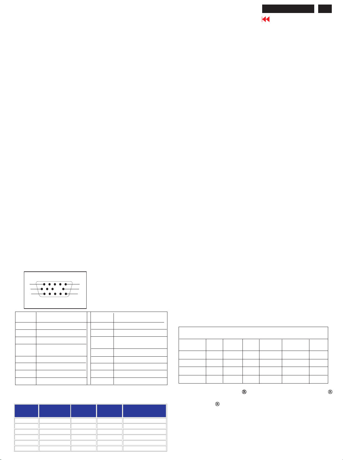
Pin assignment :
The 15-pin D-sub connector(male) of the signal cable
(IBM systems) :
1
6
11
Pin No.
1
2
3
4
5
6
7
8
Assignment
Red video input
Green video input
Blue video input
Identification output Connected to pin 10
Ground
Red video ground
Green video ground
Blue video ground
5
10
15
Pin No.
9
10
11
Assignment
No pin
Logic ground
Identification output Connected to pin 10
12
13
14
15
Serial data line(SDA)
H.Sync
V.Sync(VCLK for DDC)
Data clock line(SCL)
Physical Specifications
Dimensions : 347x367x360mm(including base)
347x367x310mm(excluding base)
weight : 9.5 Kg
Power supply : 90 - 264 VAC, 50/60HZ
Power consumption : <= 72 Watt
Operating condition
Temperature : 0 C - 40 C
OO
Relative Humidety : 20%-80%(W/O condensation)
Storage condition
Temperature : - 25 C - 65 C
OO
Relative Humidity : 20%-90%(W/O condensation)
Automatic Power Saving
If you have VESA's DPMS compliance display card or
software installed in your PC,the monitor can automaticlly
reduce its power consumption when not in use. And if an
input from a keyboard, mouse or other input devices is
detected, the monitor will automatically "wake up". The
following table shows the power consumption and
signalling of this automatic power saving features :
Power Management Definition
VESA's mode
ON
Stand-by
Suspend
OFF
VIDEO
Active
Blanked
Blanked
Blanked
H-SYNC
Yes
No
Yes
No
V-SYNC
Yes
Yes
No
No
POWER
USED
<75W
<15W
<15W
<8W
POWER
SAVING( % )
80 %
80 %
94 %
0%
LED
COLOR
Green
Yellow
Yellow
Amber
For Tne monitor is pre-set with 6 modes for optimal display size and centering as indicated in the
following table:
Mode Resolution
VGA 640 X 400 31.5 70 Non-interlaced
VGA 640 X 480 31.5 60 Non-interlaced
VESA / 75 640 X 480 37.5 75 Non-interlaced
VESA / 75 800 X 600 46.9 75 Non-interlaced
VESA / 85 800 X 600 53.7 85 Non-interlaced
VESA 1024 X 768 48.3 60 Non-interlaced
(dots x lines)
Horizontal
Freq. (KHz)
Vertical
Freq. (KHz)
Remark
This monitor is Energy Star compliant .As an ENERGY STAR
Partner, PHILIPS has determined that this product meets the
ENERGY STAR guidelines for energy efficiency.
Page 4

104S CM23 GSIII
4
Go to cover page
Front View
For detailed information about the knobs and keys,
please refer to controls
Rear View
Installation and Control
Front Controls
For an optimized adjustment of the picture following controls are
available at the front.
Power
1.Press this knob, the green LED lights and the power is ON.
2.Press this knob again, the green LED disappears and
the power is OFF.
Hotkeys
Contrast
Rotate to adjust the picture contrast level.
Brightness
Rotate to adjust the overall screen brightness as a
compensation for ambient light.
Digital Controls
Press to adjust (increase) the function selected.
Press to adjust (decrease) the function selected.
To select the level of function.
"SHIFT" LED off - control is on first level.
"SHIFT" LED on - control is on second level.
1.Power in - attach power cable here.
2.Video In - this is a cable which is already attached to your
monitor.Connect the other end of the cable to your PC.
The function pads:
H-Shift: to adjust the horizontal position of the image.
H-Size: to adjust the horizontal amplitude of the image.
V-Shift: to adjust the vertical position of the image.
V-Size: to adjust the vertical amplitude of the image.
Select level of the function pads:
Trapezoid:to correct the trapezoid distortion of the image.
Pincushion:to correct the barrel distortion of the image.
Recall: to recall original factory preset mode.
Remarks:
1.When pressing any function pad, the "Shift" LED will flash
once to indicate the function has been selected.
2.Once the limit of the adjustable range has been reached,
the shift LED will flash continuously.
Adjustment
For the monitor is pre-set with 6 modes for optimal display size
and centering as indicated in the following table:
Mode
VGA
M01
VGA
M02
M03
VGA
M04
SVGA
M05
SVGA
M06
EVGA
The set will save the user's setting parameters automatically.
After 10 seconds of key-pad inactivity, the LED will flash twice to
indicaate the parameters being saved.
Press to recall factory preset mode. (at second level)
Resolution
640 x 400
640 x 480
640 x 480
800 x 600
800 x 600
1024 x 768
Frequency
H(KHz)
31.5
31.5
37.5
46.9
53.7
48.3
V(Hz)
70
60
75
75
85
60
Remark
Non-interlaced
Non-interlaced
Non-interlaced
Non-interlaced
Non-interlaced
Non-interlaced
Page 5

Warning and Notes
104S CM23 GSIII
Go to cover page
5
Warnings
1
. Safety regulations require that the unit should be returned
in its original condition and that components identical to
the original components are used. The safety components
are indicated by the symbol .
2
. In order to prevent damage to ICs and transistors, all
high-voltage flash-overs must be avoided. In order to
prevent damage to the picture tube, the method shown
in Fig. 1 should be used to discharge the picture tube.
Use a high-voltage probe and a multimeter (position DC-V).
Discharge until the meter reading is (after approximately
30 seconds).
3 ESD
.
All ICs and many other semiconductors are sensitive to
electrostatic discharges (ESD). Careless handling during
repair can drastically shorten their life. Make sure that
during repair you are connected by a pulse band with
resistance to the same potential as the ground of the unit.
Keep components and tools also at this same potential.
4
. When repairing a unit, always connect it to the AC Power
voltage via an isolating transformer.
5
. Be careful when taking measurements in the high-voltage
section and on the picture tube panel.
6
. It is recommended that saferty goggles be worn when
replacing the picture tube.
0V
Notes
. The direct voltages and waveforms are average voltages.
1
They have been measured using the Service test software
and under the following conditions :
- Mode : 640 * 480 (31.5kHz / 60Hz)
- Signal pattern : grey scale
- Adjust brightness and contrast control for the
mechanical mid-position (click position)
. The picture tube panel has printed spark gaps.
2
Each spark gap is connected between an electrode of the
picture tube and the Aquadag coating.
. The semiconductors indicated in the circuit diagram(s)
3
and in the parts lists are completely interchangeable per
position with the semiconductors in the unit, irrespective
of the type indication on these semiconductors.
V
7
. When making adjustments,use plastic rather than metal tools.
This will prevent any short-circuit or the danger of a
circuit becoming unstable.
8
. Never replace modules or other components while the
unit is switched on.
9
. Together with the defleciton unit, the picture tube is used
as an integrated unit. Adjustment of this unit during repair
is not recommended.
10.
After repair, the wiring should be fastened in place with
the cable clamps.
11.
All units that are returned for service or repair must pass
the original manufactures safety tests.
Fig.1
Page 6

104S CM23 GSIII
6
Mechanical Instructions
Go to cover page
0. General
To be able to perform measurements and repairs on the "circuit
boards", these unit should placed in the service position first.
1. Remove the rear cover
- Open two lids with "-" type screwdriver. Refer to fig2 and fig3.
- Remove 4 screws with "+" type screwdriver.
2. Video panel
- Remove the metal shielding on rear side of Video panel by
desolder lags of metal shielding.
3. Main panel
- Disconnect the degaussing coil from Main panel.
- Remove the video panel from CRT.
- Remove the "screw" of I/F cable from Main panel.
- Disconnect the CRT ground "1701" from Video panel.
- Disconnect the Hi-Pot cap from CRT.
- Disconnect the yoke wire connector "1601" from Main panel.
- Slide the main panel out of bottom tray.
- Place Main panel in service position as shown in Fig.1.
- Mount Video panel again on CRT.
- To connect Hi-Pot cap again.
- To connect "1701" again.
- To connect the yoke wire "1601" again.
lids
lid
screws
Fig.2
screws
Fig. 1
Fig.3
Page 7

B1
120K
Deflection
104S CM23 GSIII
25
Go to cover page
B1 7503 -B
B1
43K
B3
B13
20 mV/div AC
10 mS/div
B2
B11
B12
B6
B4
B5
B7
B8
B14
B15
B16
B38
B37
B19
B17
B40
4k3
B39
750n
B43
820n
B44
B2 7503-C
0.2 V/div AC
5 mS/div
B3 7502-B
B9
B10
B20
B18
B41
B42
50 mV/div AC
5 mS/div
B21
B4 7504-C
B24
B23
B25
B26
270R
10 V/div AC
5 mS/div
B5 7504-B
B28
B27
B47
B49
0.2 V/div AC
5 mS/div
B6 7501-14
B31
B29
B30
B34
Back
B32
B33
B36
B35
B48
B50
B51
2 V/div AC
5 mS/div
B7 7501-16
1 V/div AC
10 uS/div
Forward
Page 8

104S CM23 GSIII
26
Go to cover page
B2
U-CONTROL
B8 7501 -19
B15 7501-12
B22 7501-2
B29 7508-C
B36 7401-6
B43 7615-D
B52 7801-2
B59 7801-27
B53
B52
B57
B58
B56
B60
B59
B61
B62
50 mV/div AC
10 uS/div
B9 7501-18
50 mV/div AC
10 uS/div
B10 7501-15
1 V/div AC
5 uS/div
B11 7501-24
0.2 V/div AC
5 mS/div
B16 7501-13
0.5 V/div AC
5 mS/div
B17 7501-20
0.1 V/div AC
5 mS/div
B18 7501-6
0.1 V/div AC
5 mS/div
0.2 V/div AC
5 mS/div
1 V/div AC
5 mS/div
50 V/div AC
5 uS/div
B23 7501-1 B30 7508-B B37 7605-G B44 7616-C
1 V/div AC
5 uS/div
B24 7501-29
0.5 V/div AC
5 uS/div
B25 7505-B
0.1 V/div AC
5 mS/div
B31 7401-1
1 V/div AC
5 mS/div
2 V/div AC
5 uS/div
B38 7605-D
50 V/div AC
5 uS/div
B32 7401-2 B39 7606-C
10 V/div AC
10 uS/div
B47 7623-D
50 V/div AC
5 uS/div
B48 7621-E
2 V/div AC
5 uS/div
B53 7801-11
50 mV/div AC
10 uS/div
B54 7804-C
50 V/div AC
5 mS/div
B55 7801-15
1 V/div AC
5 uS/div
B60 7801-28
1 V/div AC
5 mS/div
B61 7811-E
1 V/div AC
10 uS/div
B62 7811-B
B54
B55
1 V/div AC
5 mS/div
B12 7501-22
20 mV/div AC
5 mS/div
B13 7501-21
20 mV/div AC
10 uS/div
B14 7501-11
5 V/div AC
5 uS/div
B19 7501-4
0.2 V/div AC
5 uS/div
B20 7501-5
20 mV/div AC
5 uS/div
B21 7501-8
0.2 V/div AC
5 uS/div
B26 7505-C
2 V/div AC
5 uS/div
B27 7507-B
5 mV/div AC
5 uS/div
B28 7507-E
0.2 V/div AC
5 mS/div
B33 7401-4
1 V/div AC
5 mS/div
100 V/div AC
5 uS/div
B40 7611-E
0.1 V/div AC
10 uS/div
B34 7401-8 B41 7611-C
5 V/div AC
5 mS/div
B35 7401-5
0.5 V/div AC
5 uS/div
B42 7610-C
5 V/div AC
2 uS/div
B49 5611-3
20 V/div AC
5 uS/div
B50 5611-10
50 V/div AC
5 uS/div
B51 7631-B
20 mV/div AC
5 uS/div
B56 7801-21
2 V/div AC
5 uS/div
B57 7801-20
20 mV/div AC
5 uS/div
B58 7801-26
1 V/div AC
10 uS/div
Back
0.1 V/div AC
5 mS/div
2 V/div AC
5 uS/div
10 mV/div AC
5 mS/div
10 V/div AC
5 mS/div
2 V/div AC
5 uS/div
2 V/div AC
5 mS/div
50 mV/div AC
10 uS/div
Forward
Page 9

28
C
104S CM23 GSIII
Go to cover page
POWER SUPPLY SCHEMATIC DIAGRAM
C1 7103-4
C8 5110-1
1 V/div AC
5 uS/div
C2 7103-6
5 V/div AC
5 uS/div
C3 7103-3
0.2 V/div AC
5 uS/div
C4 7102-G
100 V/div AC
5 uS/div
C9 5110-2
100 V/div AC
5 uS/div
C10 5110-6
10 V/div AC
5 uS/div
C11 5110-8
5 V/div AC
5 uS/div
C5 7102-D
100 V/div AC
5 uS/div
C6 7102-S
0.2 V/div AC
5 uS/div
C7 5110-11
10 V/div AC
5 uS/div
C12 5110-5
5 V/div AC
5 uS/div
Back
10 V/div AC
5 uS/div
Forward
 Loading...