

Page 1
INSTALLATION
Zur Montage eignen sich gut zugängliche Plätze im Inneren des Bootes; in
der Regel am Kartentisch. Der rückwärtige Raum sollte mindestens eine
Tiefe vom 15 cm besitzen, um die Verkabelung sorgfältig und übersichtlich
und somit sicher ausführen zu können. Es empfiehlt sich, die Schalttafel
so einzubauen, daß sie später auch wieder von hinten für Erweiterungen,
Veränderungen und eventuelle Reparaturen zugänglich ist.
Für den Einbau ist ein Ausschnitt kleiner 10mm pro Seitenrand der
Schalttafel-Abmessungen vorzusehen. An den vier Befestigungslöchern
kann die Schalttafel mit Schrauben Ihrer Wahl befestigt werden.
WARNUNG
Hohe Ströme können bei zu dünnen Leitungen oder Übergangwiderständen durch korrodierte Kontakte zu überhitzten Leitungen oder
Verbindungen führen, die sich entzünden können.
Beachten Sie daher die abgedruckte Kabelquerschnittstabelle und achten
Sie auf sorgfältig ausgeführte Verbindungen und festen Anschluss.
ANSCHLUSS
Die vorverdrahteten roten Zuleitungskabel (+) 6mm2 werden an den
Pluspol der Service-Batterie angeschlossen. Beim Verlängern darf der
Kabelquerschnitt der am Stromkreisverteiler montierten Zuleitung nicht
unterschritten werden -Brandgefahr !
Die Zuleitung muss an der Batterie über eine dazwischengeschaltete
zum Zuleitungsquerschnitt richtig dimensionierte Hochstromsicherung
angeschlossen werden.
Die Verbraucherabgangsleitungen werden an den Steckkontakten der
Sicherungsautomaten angeschlossen.
Die schwarze Minusleitung (-) wird an den Minuspol der Batterie angeschlossen. Sie dient zur Versorgung der Leuchtdiodenanzeige und bei
Vorhandensein eines Voltmeters als Bezugsmasse.
ÜBERLASTUNG
Bei Überlastung oder Kurzschluß eines Stromkreises werden die angeschlossenen Verbraucher durch Auslösen des Sicherungsautomaten
abgeschaltet und die Leuchtdiodenanzeige erlischt. Nachdem der Überlastungszustand aufgehoben ist, kann der jeweilige Sicherungsautomat
durch Drücken der Auslösetaste bzw. Wiedereinschalten wieder zurückgestellt werden.
SICHERHEITSHINWEISE
• Es darf keine Veränderung am Gerät vorgenommen werden, sonst
erlischt das CE-Zeichen
• Der Anschluß des Stromkreisverteilers darf nur von Elektrofachkräften
vorgenommen werden.
• Vor dem Anschluß des Stromkreisverteilers sind die Batteriezuleitungen
abzuklemmen. Auf die richtige Polung der Batterien achten!
• Die in den Stromkreisverteilern eingebauten Sicherungsautomaten dienen zum Absichern der Zuleitungen zu den Verbrauchern.
Die Absicherung der angeschlossenen Verbraucher selbst erfolgt durch
die in den Geräten eingebauten Sicherungen.
Die vorliegende Montage und Gebrauchsanweisung ist Bestandteil
der Komponentenlieferung. Sie muß -wichtig für spätere Wartungsarbeiten - gut aufbewahrt und an eventuelle Folgebesitzer des Stromkreisverteilers weitergegeben werden.
HAFTUNGSAUSSCHLUSS
Sowohl die Einhaltung der Betriebsanweisung, als auch die Bedingungen
und Methoden bei Installation, Betrieb, Verwendung und Wartung des
Stromkreisverteilers können von philippi elektrische systeme gmbh nicht
überwacht werden. Daher übernehmen wir keinerlei Verantwortung und
Haftung für Verluste, Schäden oder Kosten, die sich aus fehlerhafter
Installation und unsachgemäßen Betrieb entstehen.
GARANTIE
Wir leisten aufgrund unserer "Allgemeinen Geschäftsbedingungen”
Garantie für die gelieferten Stromkreisverteiler. Diese Geschäftsbedingungen sind Grundlage aller Verkaufs- und Lieferangebote, sie sind in
unseren Katalogen abgedruckt und allen Angeboten und Auftragsbestätigungen beigefügt.
CE-ZEICHEN
Dieses Gerät erfüllt die Anforderungen der EU-Richtinien:
2014/30/EU „Elektromagnetische Verträglichkeit”
2013/53/EU „Sportbootrichtlinie“
Die Konformität des Gerätes mit den o.g. Richtinien wird durch das
CE-Kennzeichen bestätigt.
EINFÜHRUNG
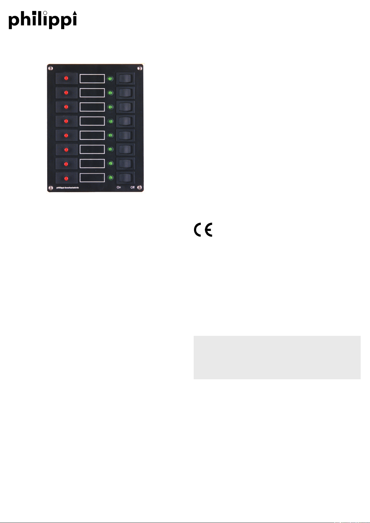
Stromkreisverteiler der Serie STV dienen zum Verteilen und Absichern der
elektrischen 12/24V-Anlage. Auf der Frontplatte befinden sich die Schutzschalter, Steuer- und Anzeigeelemente.
Jeder einzelne Stromkreis ist mit rückstellbaren Sicherungsautomaten und
Freiauslösung ausgestattet. Bei den Schalttafeln der Serien STV 100-400
wird der Stromkreis über einen separaten Schalter ein- und ausgeschaltet.
Die Leuchtdiodenanzeige meldet, ob der entsprechende Stromkreis
eingeschaltet und betriebsbereit ist.
Einige Modelle sind mit zusätzlichen Batteriespannunganzeigen ausgerüstet. Die zusätzlichen Stromanzeigen geben Aufschluß über den aktuell
fließenden Entladestrom.
Die einzelnen Stromkreise werden auf der Frontseite mit den beiliegenden
Stromkreiskennzeichen durch Aufkleben in die dafür vorgesehenen Felder
beschriftet.
Mehrere Stromkreisverteiler neben- oder übereinander montiert, bilden ein
System. Die Schalttafeln eignen sich für Batteriespannungen von 12V
bzw. 24V, ohne dass Modifikationen vorgenommen werden müssen.
LIEFERUMFANG
Stromkreisverteiler
Bedienungsanleitung
1 Bogen selbstklebende Stromkreiskennzeichen
ZUBEHÖR/ERSATZTEILE
Stromkreiskennzeichen (1 Bogen) STKZ-D, STKZ-GB, STKZ-FR,
STKZ-NL, STKZ-DK, STKZ-I
Flachsteckhülsen 6,3mm -2,5mm
2
FSH 6,3/1,5-2,5
Wippschalter 0-1 Bestell-Nr. 5 1801 1102
Leuchtdiode grün Bestell-Nr. 6 0005 0600
Sicherungsautomat STV 1xx/3xx/4xx E-T-A 1140-F114-P1M1-xA
TECHNISCHE DATEN
Maße siehe Katalog
Betriebsspannung DC 10-28V
Absicherung 8A (Standard), alternat.: 4A / 6A / 10A / 12A / 16A
Frontplatte Aluminium schwarz kunststoffbeschichtet
Stromkreisverteiler
Serie 100
BEDIENUNGSANLEITUNG
philippi elektrische systeme gmbh www.philippi-online.de
Neckaraue 19 [email protected]
D-71686 Remseck am Neckar Tel:+49 (0)7146/8744-0 Fax:-22
Page 2
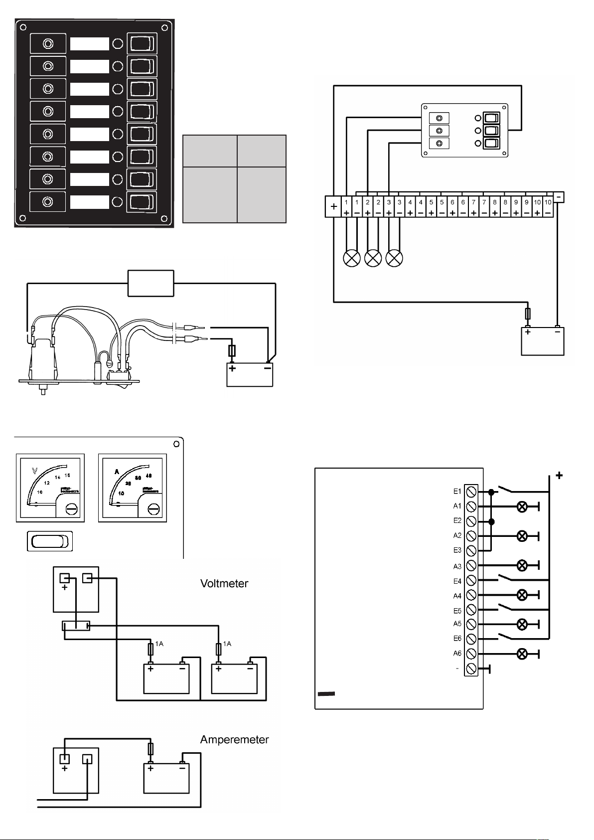
Stromkreisverteiler
STV 1xx,
STV 3xx,
STV 4xx
Leiter- Stromquerschnitt belastung
mm2 A
1,5 12
2,5 17
4 23
6 29
10 40
Volt-, Amperemeter
STV 3xx
STV 4xx,
Anschluss einer
Reihenklemme RKL
1
Verbraucher
2
2
1
--
+
zur Schalttafel
Buglaterne Bb
Buglaterne Stb
Hecklaterne
Ankerlaterne
Dreifarbenlaterne
Dampferlicht
Minus
J 1
Anschluss der Positionslampenkontrolle POS 6E
Kabelquerschnitt:
für den Anschluss der Positionslaternen: 2,5 mm² (herkömmliche Lampen),
min.1mm² für LED-Positionslampen.
Buglaterne:
Bei Verwendung einer Zweifarbenbuglaterne wird diese Laterne an A1
angeschlossen und der Jumper (Brücke) J1 muss eingesteckt sein
(Auslieferungszustand).
Werden zwei getrennte Seitenlaternen (Bb./Stb.) verwendet, muss der
Jumper (Brücke) J1 abgezogen werden.
Page 3
INSTALLATION
Easily accessible places inside the boat are suitable for installation; usually
at the chart table. The rear space should have a depth of at least 15 cm in
order to be able to carry out the wiring carefully and clearly and thus safely. It is advisable to install the distribution panel in such a way, that it can
later be accessed from the rear for extensions, modifications and possible
repairs.
For the installation, make a cut-out of less than 10mm per side edge of
the panel dimensions. The panel can be fixed with screws of your choice.
WARNING
High currents can lead to overheated cables or transition resistance if the
cables are too thin.
Corroded contacts can lead to overheated cables or connections, which
may ignite.
Therefore, observe the printed cable cross-section table and make sure
that the connections are carefully made and firmly connected.
CONNECTION
The pre-wired red supply cables (+) 6mm2 are connected to the positive
pole of the service battery. When extending, the cable cross-section of the
supply cable mounted on the distribution panel must not be undercut -
risk of fire!
The supply cable must be connected to the battery via an interconnected
high-current fuse that is correctly dimensioned for the supply cable crosssection.
Theoutgoing consumer cables are connected to the plug contacts of the
circuit breakers.
The black negative lead (-) is connected to the negative pole of the
battery. It is used to supply the light-emitting diode display and, if a voltmeter is present, as reference earth.
OVERLOAD
In the event of an overload or short circuit of a circuit, the connected
loads are switched off by tripping the circuit breaker and the LED display
extinguishes.
After the overload condition is removed, the respective circuit breaker can
be reset by pressing the release button or switching it on again.
SAFETY INSTRUCTIONS
• No changes may be made to the unit, otherwise the CE mark will be
invalidated.
• The power distribution panel may only be connected by qualified
electricians.
• Before connecting the circuit distributor, disconnect the battery
connection cables. Ensure that the polarity of the batteries is correct!
• The automatic circuit breakers installed in the distribution panels serve
to protect the supply lines to the consumers.
The connected loads themselves are protected by the fuses installed in
the units.
The assembly and operating instruction is a component of
the STV package. It must be kept (for reference).
Importantly: - for later maintenance work - and for the use
of subsequent owners of the equipment.
DISCLAIMER
Both the compliance with the operating instructions and the conditions and
methods for installation, operation, use and maintenance of the
distribution panel cannot be monitored by philippi electrical systems
gmbh. Therefore, we assume no responsibility or liability for any
loss, damage or expense resulting from improper installation or improper
operation.
WARRANTY
philippi elektrische systeme gmbh grants a two year limited and not transferable warranty for the first buyer of this equipment, carried out due to our
"general trading conditions". These trading conditions are basis of all sales
and delivery offers, they are printed and attached to all offers and confirmation of orders in our catalogues.
CE-CONFORMITY
This product fulfills the requirements of the European Regulation:
2014/30/EU “electromagnetic compatibility”
2013/53/EU “Recreational Craft Directive RCD”
The conformity of the equipment is confirmed by the CE mark.
INTRODUCTION
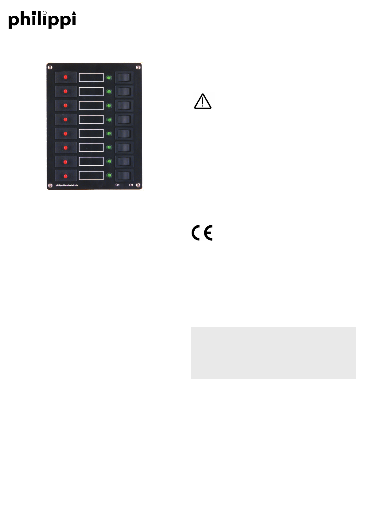
Distribution panels series STV are used to distribute and protect the
electrical 12/24V system. The circuit breakers, control and display elements are located on the front. Each individual circuit is equipped with
resettable automatic circuit breakers and free release. On the distribution
panels series STV 100-400 series, the circuit is switched on and off via a
separate switch. The LED display indicates whether the corresponding
circuit is switched on and ready for operation. Some models are equipped
with additional battery voltage indicators. The additional current indicators
provide information about the currently flowing discharge current.
The individual circuits are labelled on the front panel with the enclosed
circuit labels by sticking them in the spaces provided.Several circuit
distribution panels mounted next to or on top of each other form a system.
The distribution panels are suitable for battery voltages of 12V or 24V
without the need for modifications.
CONTENT
Power distribution panel
This manual
1 set of self adhesive labels STKZ
ACCESSORIES (TO BE ORDERED SEPARATLY)
Self adhesive labels (1set) STKZ-D, STKZ-GB, STKZ-FR,
STKZ-NL, STKZ-DK, STKZ-I
Stack connectors 6,3mm -2,5mm2 FSH 6,3/1,5-2,5
Switch 0-1 Order-no. 5 1801 1102
LED green Order-no. 6 0005 0600
Circuit breaker STV 1xx/3xx/4xx E-T-A 1140-F114-P1M1-xA
TECHNICAL DATA
Dimensions see catalogue
Rated voltage DC 10-28V
Fuse size 8A (standard), alternat.: 4A / 6A / 10A / 12A / 16A
Panel Aluminium black coated
Power distribution panel
series 100
INSTRUCTION MANUAL
philippi elektrische systeme gmbh www.philippi-online.de
Neckaraue 19 [email protected]
D-71686 Remseck am Neckar Tel:+49 (0)7146/ 8744-0 Fax:-22
Page 4
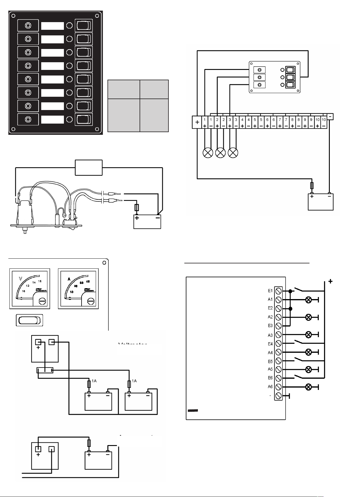
Power distribution panel
STV 1xx,
STV 3xx,
STV 4xx
Wire cross Current
section rating
mm2 A
1,5 12
2,5 17
4 23
6 29
10 40
Volt-, Ammeter
STV 3xx
STV 4xx,
Voltmeter
Ammeter
Connection of a
terminal bar RKL
1
Consumer
2
2
1
--
+
to panel
Bowlantern Port
Bowlantern Stb
Stern light
Anchor light
Tricolour light
Steaming light
Minus
J 1
Connection of the position light monitor POS6E
Wire cross section:
of the connection of the position lights: 2,5 mm² (normal bulbs), min.1mm²
for LED-navigation lights.
Bowlantern:
If you`re using a twocolour - bowlantern, you have to connect it to outlet
A1 and the jumper has to remain (delivery status).
If there are two separate position lights (port/starboard), you have to remove the jumper J1.
 Loading...