

Page 1
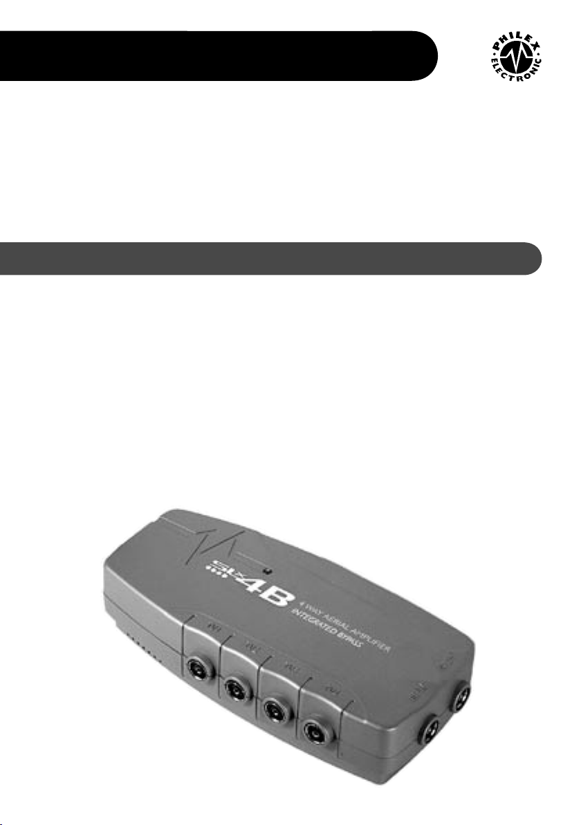
SLxB AERIAL AMPLIFIERS
27820
27822
27820BM
27822BM
27820BMSP
27822BMSP
Introduction
USER GUIDE
Philex Customer Careline 08457 573479
The SLxB series
ampliers are
designed to improve
the picture and
sound quality of TV
and FM radio signals
and distribute these
signals around your
home.
All SLxB ampliers
have an integrated
by-pass designed
to allow the user to
control digital satellite
receivers from a
second TV without
additional equipment
apart fron a Link
device and a digital
satellite or compatible
universal remote
control.
For added safety
the SLxB series has
built in short circuit
protection on each
individual output.
Should a short circuit
be detected the SLxB
amplier will only
shut down the output
with the short circuit;
the other outputs will
continue to function
as normal.
The ampliers are
easy to install and
fully automatic in
operation, meaning
that no user
adjustment is required.
The low running cost
permits continuous
operation.
Page 2
Setting up the SLxB Aerial Amplier
Note: SLx2B operation is similar to SLx4B but with TV1 and TV2 outputs only.
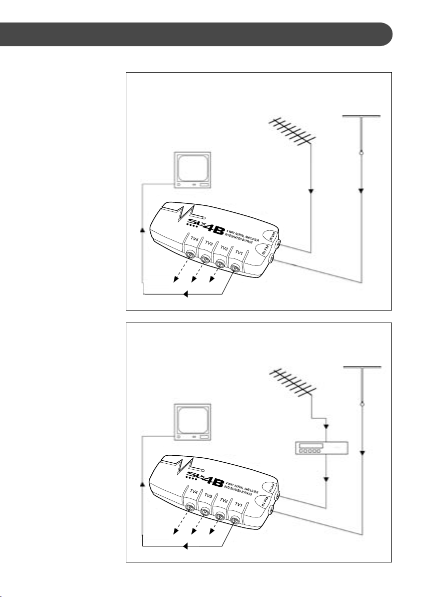
SET UP 1:
TV and FM Radio
Distribution
1. Connect your UHF
aerial downlead to the
IN UHF socket of the
amplier and the FM
aerial downlead to the
IN FM socket.
2. Connect your TVs and
FM Tuners to any of the
amplier TV sockets in
any combination.
All TVs and Tuners will
receive the appropriate
amplied signal.
SET UP 2:
Video Cassette Recorder
(VCR) Playback
1.
Connect your UHF aerial
downlead to the RF
input socket of the VCR.
2. Connect the RF output
lead of the VCR (usually
connected direct to
the TV) to your aerial
amplier IN UHF socket.
TV and VCR playback
signals will now be
available to any TV you
now connect to the
amplier TV sockets.
SET UP 1
TV AND FM RADIO
DISTRIBUTION
Aerial
ylead
Additional
TV sets /
Hi-Fi
Main
TV
SET UP 2
TV/ VCR/FM
DISTRIBUTION
Aerial
ylead
Main
TV
UHF (TV)
Aerial
downlead
UHF (TV)
Video
Recorder
Coaxial
aerial lead
Aerial
downlead
Aerial
downlead
FM (Radio)
and/or
VHF TV on
EIR modems
FM (Radio)
and/or
VHF TV on
EIR modems
NB. Some older VCRs will
not pass TV signals whilst
in playback. This can
sometimes be remedied
by contacting your local
dealer for advice.
Additional
TV sets /
Hi-Fi
Aerial
downlead
Page 3
SET UP 3
TV/ VCR/SAT/FM
DISTRIBUTION
UHF (TV)
Satellite
Video
Recorder
Main
TV
Additional TV sets/ Hi-Fi
Scart
connection
RF1 out
Satellite
Receiver
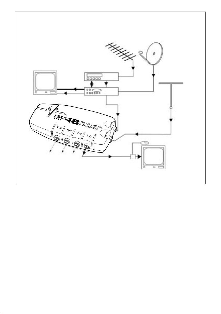
SET UP 3:
Satellite Receiver Signal Distribution
1. Connect your UHF aerial downlead into the
VCR’s UHF aerial input. If you do not have a
VCR, plug the UHF aerial downlead into the
satellite receiver’s UHF aerial input and ignore
all further references to VCRs.
2. Connect the VCR RF output lead to the aerial
input on the satellite receiver.
3. Connect the satellite receiver via the Scart
outputs to the VCR and TV.
RF2 out
Aerial ylead
Satellite
output lead
Aerial
downlead
Aerial
ylead
Link
TV 2
FM (Radio)
and/or
VHF TV on
EIR modems
Aerial
downlead
5. Connect an output lead from the satellite receiver
RF2 output to your aerial amplier IN UHF socket.
UHF TV, VCR playback and satellite receiver signals
will now be available to your main TV and to any TV
you now connect to the amplier TV sockets. For FM
connection see SET UP 1.
To operate your digital satellite receiver from one of
the connected TVs you will now need to install a
Link device such as the SLx Link.
4. Connect an output lead from the satellite
receiver RF1 output to the aerial input on
your main TV.
N.B. It may be necessary to retune the output
channel of your VCR when used with a satellite
receiver. Consult your VCR user guide.
Page 4

Troubleshooting
If you are still experiencing reception
problems after the installation of your
SLxB Aerial Amplier, please refer below.
Analogue Terrestrial TV
Snowy Picture
A faint, grainy or snowy picture is generally caused
by a weak signal. Normally the TV transmitter will
be a long way away. A possible improvement could
be made by reducing the aerial downlead losses,
installing a high gain aerial and by adding a low
noise masthead amplier or signal booster. In a
small number of cases, a snowy picture can also be
caused by a TV signal that is too strong.
‘Herringbone’ Pattern
‘Herringboning’ is generally caused by too strong a
TV signal or by a local high power transmitter such
as CB, amateur or taxi radio. Your TV sound may be
affected as well as the picture. Using an attenuator
will reduce the gain of an aerial signal and improve
the overall picture.
Digital Terrestrial Television
Similarly blocking and even a completely blank
screen with no sound can result if the input
signal to the set top box is too high. The digital
cliff
refers to the rapid change from the picture
and sound being perfect, to disappearing
altogether.
When interconnecting equipment and to get the
best carrier to noise, place the digital terrestrial
television set top box as the rst item in the
signal path followed by any video or satellite
receiver.
Fitting a high gain wideband roof aerial may also
improve the reception and signal quality.
Digital signals are generally immune to ghosting
or multipath reections. They remain perfectly
receivable under conditions where an analogue
signal would suffer ghosting.
For specic help with DTT reception problems,
log onto www.dtg.org.uk.
Digital Satellite Television
With digital reception, a weak signal or
incorrectly aligned dish will cause the picture
and sound to block or disappear. Check both the
alignment of the dish and skew angle of the LNB.
Unlike analogue TV signals that can still be
viewed under weak signal strength conditions,
with digital terrestrial signals blocking/freezing
and/or loss of digital picture and sound can be
caused by insufcient digital signal and carrier to
noise ratio.
If problems persist, please contact
Philex Customer Careline: 08457 573 479
(Local rate – UK only)
Technical Support: http://technical.philex.com
Intermittent Connections
Make sure all RF cable to connector joints are
tight (both inner and outer) including all yleads
and outlet plate connections.
© Philex Electronic Ltd. 2004
 Loading...