

Page 1

Troubleshooting
© Philex Electronic Ltd. 2008. v1
TV Signal Boosters
USER GUIDE
Introduction
Philex Customer Careline 08457 573479
Congratulations on the purchase of your TV signal booster. The CCA111 and CCA121 are ideal for boosting TV
aerial signals when reception is poor. The CCA141 and CCA161 are designed to distribute TV signals around your
home without loss of signal strength. All CCA boosters will amplify both analogue and digital TV signals.
To receive terrestrial digital TV you will need to make sure that your existing aerial and cabling are suitable
and in good enough condition to receive digital terrestrial TV services (e.g. Freeview™). If any of your TVs do
not have a built-in Freeview™ receiver you will need to fit a set-top or Scart plug-in type Freeview™ receiver.
CCA111
CCA121
CCA141
CCA161
Distributing the aerial signal around your home
Analogue Terrestrial TV
Snowy Picture
A faint, grainy or snowy picture is generally caused by
a weak signal. Normally the TV transmitter will be a
long way away. A possible improvement could be made
by reducing the aerial downlead losses, installing a
high gain aerial and by adding a low noise masthead
amplifier or signal booster. In a small number of cases, a
snowy picture can also be caused by a TV signal that is
too strong.
‘Herringbone’ Pattern
A herringbone pattern is generally caused by too strong
a TV signal or by interference from a local high power
transmitter such as CB, amateur or taxi radio. Your TV
sound may be affected as well as the picture. Using an
attenuator will reduce the gain of an aerial signal and
improve the overall picture.
Digital Terrestrial Television
Unlike analogue TV signals which can still be viewed
under weak signal strength conditions, with digital
terrestrial signals blocking/freezing and/or loss of digital
picture and sound can be caused by insufficient digital
signal and carrier to noise ratio.
Similarly blocking and even a completely blank screen
with no sound can result if the input signal to the set
top box is too high. The digital cliff refers to the rapid
change from the picture and sound being perfect, to
disappearing altogether.
For specific help with DTT reception problems,
log onto *www.digitaluk.co.uk/
No picture: Check all connections from aerial to TV.
Poor picture: Check all connections from aerial to TV.
Check aerial is properly aligned to the correct
transmitter.
If the aerial has been loft mounted try mounting
outside.
Make sure new digital coax cable has been used
throughout the installation.
Check the transmitter signal is not obstructed by nearby
trees or buildings.
If in a very weak signal area or for long cable runs,
installing a masthead amplifier will improve the signal.
If in a strong signal area the signal strength may need to
be reduced by fitting an attenuator.
Intermittent Picture: Make sure all RF cable to
connector joints are tight (both inner and outer)
including all flyleads and surface outlet connections.
To Prevent Overheating
The recommended clearances and other precautions
given in the installation section of these instructions
must be observed to prevent overheating.
In addition, the booster should not be fixed where it is
likely to become smothered by curtains or other fabrics,
etc., or other thermal insulation materials in a roof space
or similar building void. The unit should not be left
resting on a carpet.
Cable Installation
Do not install cable - Closer than 50mm to mains or
telephone wiring.
Under carpets in areas likely to be walked on regularly.
With sharp bends at corners.
Other Precautions
Your TV signal booster and power adaptor are not
waterproof and are for indoor use only.
They must not be fixed where they could be exposed to
dripping or splashing water. Objects containing liquids
should not be placed on or near the appliance.
To prevent risk of fire, no object with a naked flame
should be placed on or near the appliances or the wiring
to them.
Mains Power Adaptor
Always use the power adaptor supplied with your CCA
TV signal booster. In the unlikely event that this is
broken or lost you must use a regulated power supply
with an output of 12VDC 100mA.
General Safety Precautions
For further information or any queries please contact
Philex Customer Careline: 08457 573 479
(Local rate – UK only)
Technical Support: http://technical.philex.com
Waste electrical products should not
be disposed of with household waste.
Please recycle where facilities exist.
Check with your Local Authority for
recycling advice.
Planning Your Distribution System - Choosing a Location for the TV signal booster
Your TV signal booster (CCA) may be fitted in any convenient position, the most popular being the
sitting room near your existing TV aerial socket. Alternatively it may be easier to run cable to your
other rooms from the loft or some other location. In choosing a location, consider the following:
a) The booster power adaptor needs to be plugged into the mains, so it must be near a mains socket.
b) You will need to run cables from the CCA booster to each outlet point and to minimise loss of signal
strength cable runs should be kept as short as possible.
c) You must be able to get the cable from the aerial to the input of the booster (via the DVR/VCR if you
wish to distribute signals from these as well as from your aerial)
Locating the TV signal booster
in the main sitting room
Aerial*
Downlead
Power
Supply
PF100 Cable Aerial Flyleads
Locating the TV
signal booster
in the loft
Aerial*
Downlead
Power
Supply
Coax plugs, sockets, leads and cables are not supplied with your CCA booster. For optimum digital
reception always use fully screened cables and outlets recommended for digital use.
*Aerial downleads and main room aerial outlet are
presumed to be already installed and are not supplied
Existing*
Aerial Outlet
Page 2
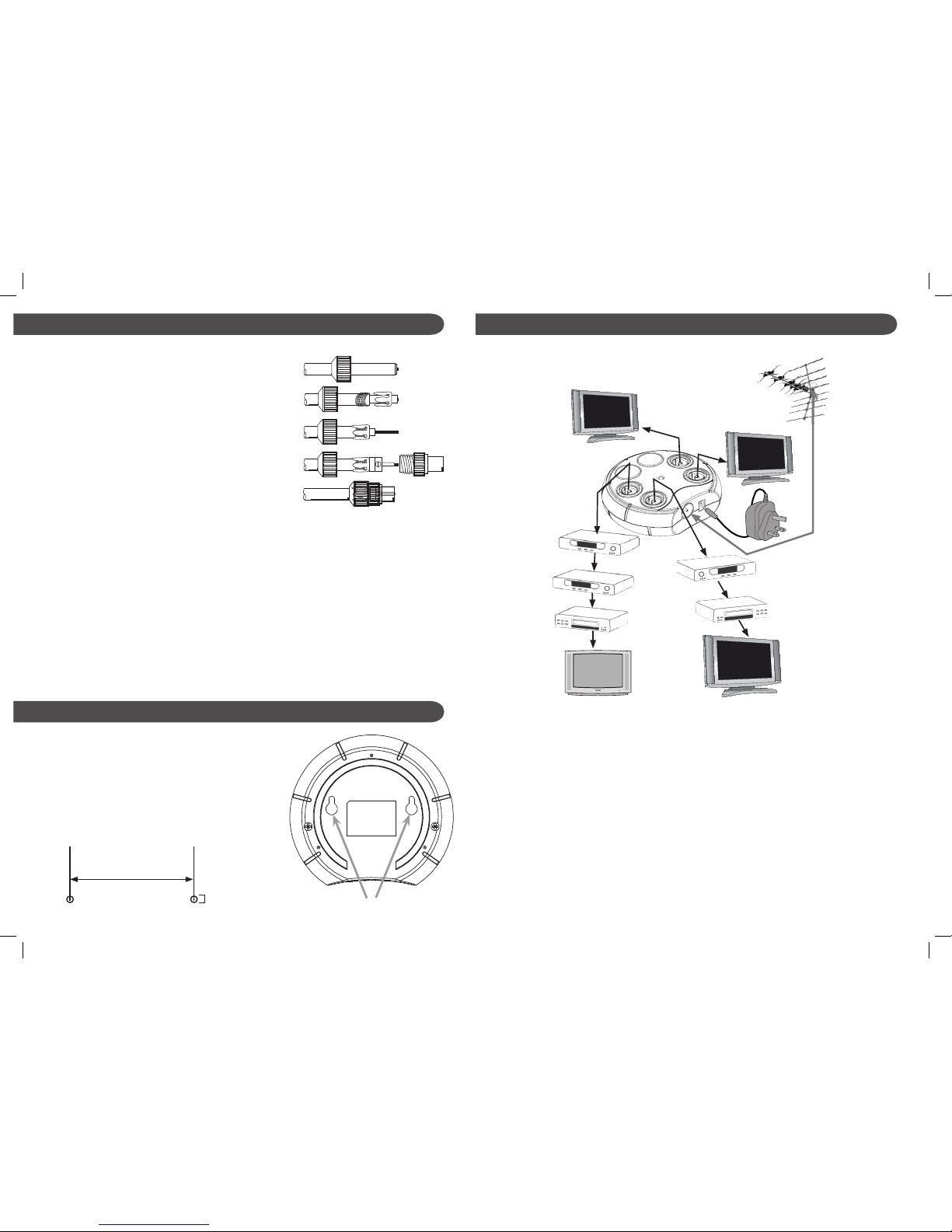
Booster Connections
You will need to fit coax plugs (not supplied) to connect
cables to the TV signal booster, where available follow
manufacturers instructions otherwise use the instructions
below which are suitable for most coax plugs
1. Unscrew coax plug housing and slide cap over cable.
2. Strip 23mm of cable outer sheath.
Gather copper braid, wrap around outer sheath,
slide claw over braid and crimp.
3. Strip 18mm of inner insulation to leave 5mm exposed.
4. Undo screw on plug/clamp, slide clamp over inner wire
& tighten screw.
5. Reassemble plug and trim inner wire flush with plug.
When running cables from the booster to the coax outlet
positions, if drilling through walls be careful to avoid pipes
and other cables. Use cable clips (not supplied) to secure
cables.
When wiring coax outlets:
Follow manufacturers instructions.
Make sure you tighten all screws and trim away any loose
strands of braid from the coax cable that might come into
contact with the central conductor or centre terminal.
1
2
3
4
5
Wiring Coax Plugs and Coax Outlets
UHF (TV )
Aerial
Aerial Flylead
Main TV
VCR/DVR*
Freeview™
Receiver
VCR/DVR*
Aerial
Downlead
Aerial
Flylead
1. Connect your UHF aerial downlead to the input on your CCA TV signal booster.
2. If connecting to a digital TV with built in Freeview™ receiver connect one end of a TV aerial flylead to any of
the TV signal outputs 1, 2, 3, 4 on your CCA booster and the other end to the ANTENNA IN (ANT IN,
UHF IN) coax socket on your TV. This applies when the TV is in the same room as the booster.
3. For TVs situated in remote rooms connect the cable running to the remote coax outlet to any of the
outputs 1, 2, 3, 4 on your CCA booster. Connect one end of a TV aerial flylead to the surface socket and the
other end to the ANTENNA IN (ANT IN, UHF IN) coax socket on your TV.
4. For older TVs a separate Freeview™ set top or plug in receiver will be required. This should be
connected to the surface outlet by a TV aerial flylead to the ANTENNA IN (ANT IN, UHF IN) coax socket on
your Freeview™ receiver. The Freeview™ receiver will then usually be connected to a TV via a Scart lead.
5. If a video recorder or DVD recorder is to be included in the system this should be connected between the
amplifier/aerial outlet and the digital TV or for older TVs between the Freeview™ receiver and the TV.
**Please note that although satellite signals can be distributed using this kit, it will not be possible to control
your Sky™ box from the remote locations as the CCA TV signal booster doesn’t have digital bypass.
Sky™ boxes can be connected locally to any of the TVs providing they have an individual feed from a satellite
dish. Sky™ box should be connected between Freeview™ receiver (if present) and TV or between Freeview™
receiver and VCR/DVR (if present) - see above.
TV Distribution Analogue and/or Digital plus optional VCR or DVR connection
Aerial Flylead
Aerial Flylead/
Scart/HDMI
Aerial Flylead
Satellite
Receiver**
Aerial Flylead/
Scart/HDMI
Satellite
Receiver**
Aerial Flylead/
Scart/HDMI
Aerial Flylead/
Scart/HDMI
*VCRs, DVRs and satellite
receivers can be connected as
shown - if required.
Prepare holes 41mm apart
for wall mounting
Wall mounting your booster
Your CCA TV signal booster has two keyhole slots
on the reverse allowing you the option of wall
mounting your booster.
You will need suitable screws (2.5mm diameter)
and wallplugs (not supplied).
Wall mounting slots
2.5mm
 Loading...