

Page 1
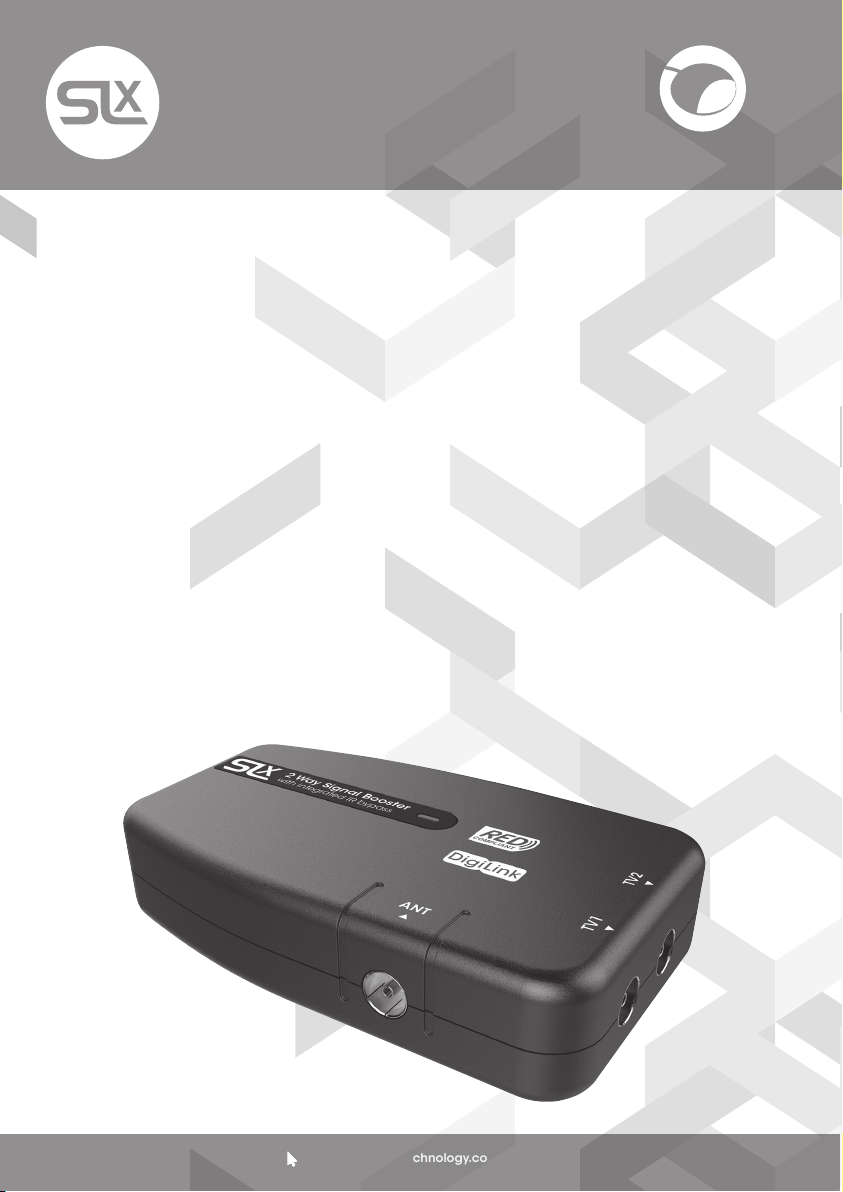
2 Way Signal Booster
with IR Bypass
27822BMR
User Guide
Introduction
Congratulations on the purchase of your new
SLx Booster. SLx is renowned for producing
high quality electrical accessories and
signal distribution products. Slx Boosters
have a number of features that assist quality
distribution of your TV and/or Radio signals
around your home, including:
• More efcient Switch-Mode Power Supply -
these run cooler saving energy whilst also
making them safer in your home
• Improved gain atness delivering a better
balance across the performance range
• Lower noise gure for optimimum picture
and sound quality
• Greater signal handling capacity to cope
with more channels
• Coaxial connectors – simple to plug in to
standard aerial connections
We are sure you will enjoy using your SLx
Booster, it’s easy to install and incorporates
the latest technology for energy efcient,
long-term, continuous use.
DigiLink
If you have any queries please get in touch
with our technical department at
www.slxtechnology.com/support
Additional Features
SLx Bypass boosters have an IR bypass circuit
and are DigiLink compatible, which means
you have the option to control a digital
satellite receiver via a Link-eye in another
room using the original or a compatible
remote control.
SLx Bypass boosters provide 9V DC on every
outlet to power a Link-eye but also have shortcircuit protection to prevent overload. If the
booster detects a short-circuit it will only shut
down the power on the outlet with the short,
all other outlets will continue to function as
normal.
Please Note: To view output from the
satellite RF2 output you will need a TV
with an analogue tuner.
All SLx boosters comply with RED (The Radio
Equipment Directive 2014/53/EU).
Support:
www.slxtechnology.com/support
Page 2
General Safety Precautions
To Prevent Overheating
The recommended clearances and other precautions given in these instructions must be
observed to prevent overheating. In addition, units should not be positioned where they are
likely to become covered by curtains, fabric or insulating material. The amp should not be
left resting on a carpet.
Other precautions
These appliances are not waterproof, they are intended for indoor use only and must not be
positioned where they could be exposed to dripping or splashing water. Objects containing
liquids should not be placed on or near the amplier.
To prevent re, make sure the unit and attached cabling is installed well away from naked
ames and other heat sources.
Mains Plug
Your amplier is supplied with a standard mains plug already tted, if you need to change
the plug use a competent professional (ELECSA or NICEIC) to make the connection.
If you need to change the fuse use a 3 Amp fuse to BS1362 carrying the ASTA or BSI
approved mark and ret the plastic fuse carrier.
Before Installing Please Note
Applications
SLx DigiLink Boosters are suitable for digital TV
signal distribution Ch21-60. if you are affected
by 4G interference in your area you may need
a Ch60 lter (currently available from at800
free of charge).
Installation
Important note: attention is drawn to the
General Safety Precautions Panel above
which contains advice on safe installation
and operation of these products.
Location
Choose a location for the booster from which
it is convenient to run cables from the
antennas and to the system outlets. Typical
examples of suitable locations are a loft space
or a cupboard. In weak signal areas it is best
to keep the aerial cables as short as possible.
Select a cool, dry location to install the
amplier. This means a location where the
ambient temperature will remain between
-10°C and +40°C, and which is free from risk of
dripping or splashing water.
The xing location should allow adequate
access to the equipment for wiring and
maintenance. Clearance of at least 25mm
should be allowed around the left hand
side and top of the unit for ventilation. More
clearance will be needed on the other sides
to allow access for cables.
Fixing
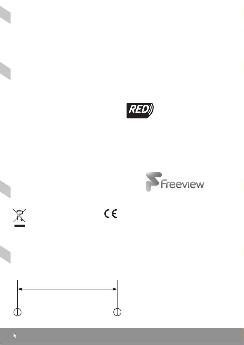
The booster should be xed to a wall or other
suitable hard surface using the keyhole slots
on the back of the housing and suitable
screws and wall plugs, a template is provided
on page 6. The booster should not be left
supported by its own wiring, nor should it be
left resting on a carpet or other insulating
and/or inammable surfaces.
Signal Connections
Input and output signal connections are
made using IEC coax connectors. Good
quality plugs and digital quality double
screened coaxial cable should be used to
ensure optimum performance from your
booster.
Using the Booster with a Sky™ Digibox
1. When using this booster with a Sky Digibox,
the booster must be fed from the RF OUT-2
socket of the Digibox. However if the RF
Channel is set to 59 or above (68 is usually
the default channel) you will need to reset
it to a channel from 21-58 in the Digibox
Setup Menu.
2. Later Digibox models such as the Sky+HD
2TB are not tted with an RF OUT2 output
and you will need an I/O converter such as
the Labgear MRX600K to distribute signals
from the Digibox to other TVs.
3. To view satellite RF2 output TVs require an
analogue tuner.
Support:
www.slxtechnology.com/support
2
Page 3
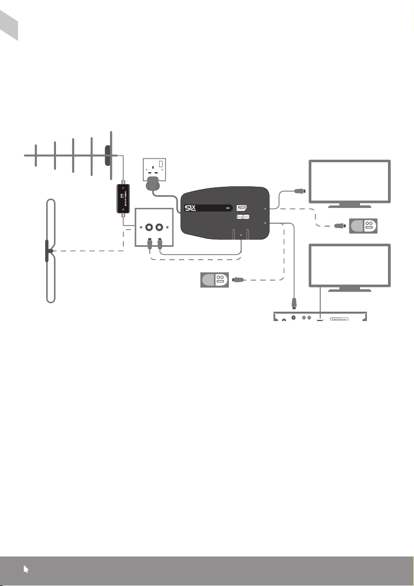
Installing your Booster - For aerial signal distribution:
1. Connect your UHF aerial downlead to the
UHF socket and connect your FM/DAB
aerial downlead (if applicable) to the FM
socket on the amplier.
2. Connect your TVs and DAB/FM tuners
to any of the
booster’s
TV sockets in any
combination.
UHF Aerial
Please Note:
If your TV does not have a built-in Freeview™
receiver you will need to connect your TV to
the amplier via a Freeview™ set top box.
TV
4G Filter
(If needed)
approved
2 Way Signal Booster
with integrated IR bypass
ANT
DAB/FM
Aerial
DAB Radio
PVR/
Freeview Box
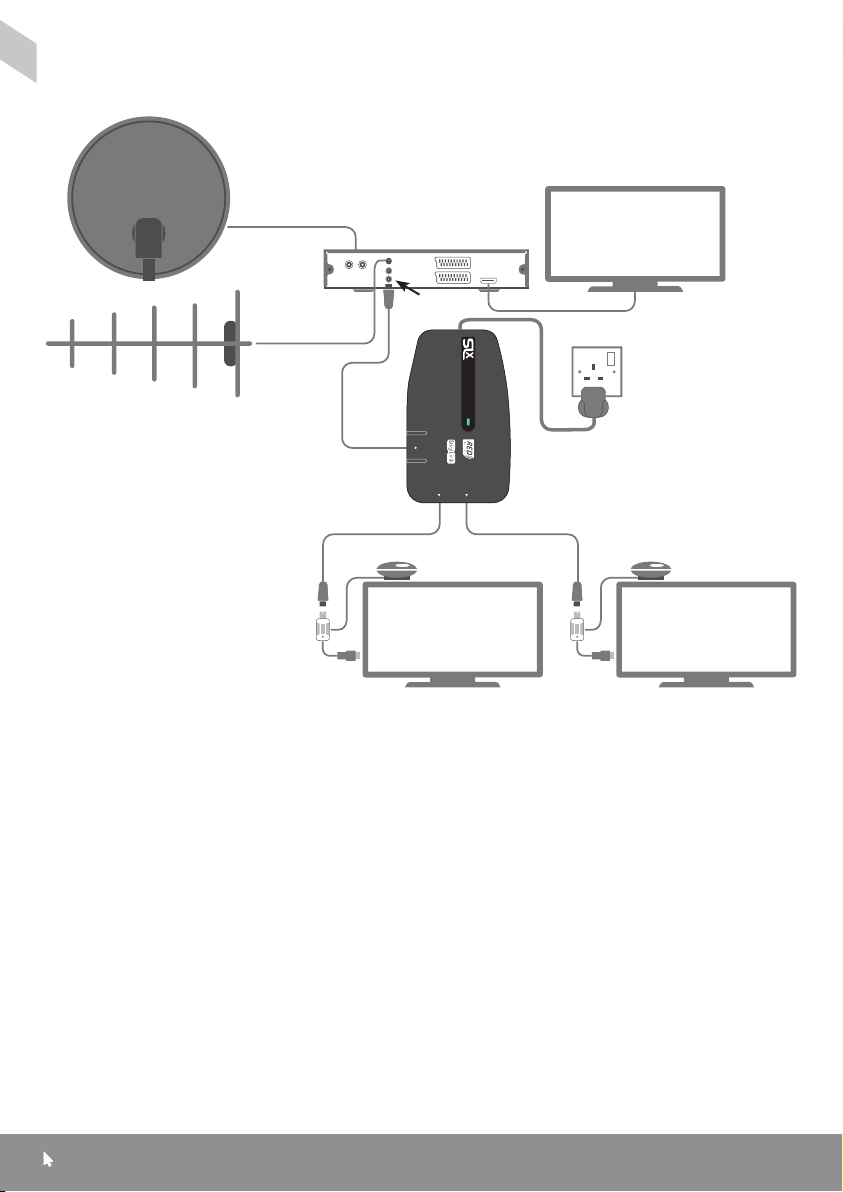
For signal distribution from a Satelllite Receiver
Please Note: To view output from the
satellite RF2 output you will need a TV with
an analogue tuner.
1. Connect your UHF aerial downlead to
the aerial input on your Satellite Receiver
and connect your FM aerial downlead
(if applicable) to the FM socket on the
booster.
2. Connect an aerial y-lead from the RF2
output on the Satellite Receiver to the UHF
input on the booster.
3. Connect your TVs and FM tuners to
any of the booster’s TV sockets in any
combination. Once connected, you can
tune each television to digital terrestrial
channels* and a channel for satellite
viewing.
Note: Only one satellite channel can
be viewed at any one time without the
use of additional satellite receivers and
subscriptions.
Note: To operate your digital satellite receiver
from one of the connected TVs you will now
need to install a Link device such as the SLx
Link.
Note: To view digital terrestrial channels an
aerial must be connected to the Aerial IN
socket on the satellite. Also connected TVs
must have a built-in Freeview™ receiver or be
connected to the booster via a Freeview™ set
top box.
TV1 TV2
TV
Support:
www.slxtechnology.com/support
3
Page 4
Signal distribution from a Satelllite Receiver
Satellite
Dish
Satellite
Receiver
RF2
UHF Aerial
ANT
TV1 TV2
TV TV
TV
2 Way Signal Booster
with integrated IR bypass
Digi-Link EyeDigi-Link Eye
Resetting the RF Channel on a Digibox
1. Switch on your Sky™/Sky+™/ Sky+ HD™
receiver and view on your main television.
2. Press the SERVICES button on your
Sky™ remote.
3. Select SYSTEM SETUP option (for SKY+
HD there is no SYSTEM SETUP option press
0 instead).
Support:
www.slxtechnology.com/support
4
4. Press the following buttons in sequence:
0, 1, SELECT (for SKY+ HD this is a hidden
option and does not appear on screen).
You should now see the installers’ menu.
5. Select the RF channel number option and
key in a new channnel number from 21-58
and select ‘Power On’.
Make a note of the channel number you
choose as you may need it when tuning
your other TVs.
Page 5
Troubleshooting
If you experience reception problems after
installing the your booster, please see below:
No picture or sound
Is the signal reaching your TV? Check:
- Everything, including the booster is
switched on
- Coaxial connections are correctly made
(no braid or foil touching the inner core)
Picture or sound breaking up
- Use the best wideband aerial ideally tted
outdoors
- Use good quality coax cable, poorly
screened cable can pick up noise
- In some cases too much signal can cause
signal break-up which can be solved
by tting an attenuator to the input to the
booster
For specic help with digital TV reception
problems, visit www.digitaluk.co.uk or
www.bbc.co.uk/reception/television/
freeview/reception_problems
Problems with satellite television
If you are experiencing any problems with
your satellite television picture, check that
all cables and connectors have been tted
correctly. If the problem persists it is probably
due to the dish alignment or a temporary
problem with the channel transmissions.
Please contact your local satellite dealer if the
problem persists.
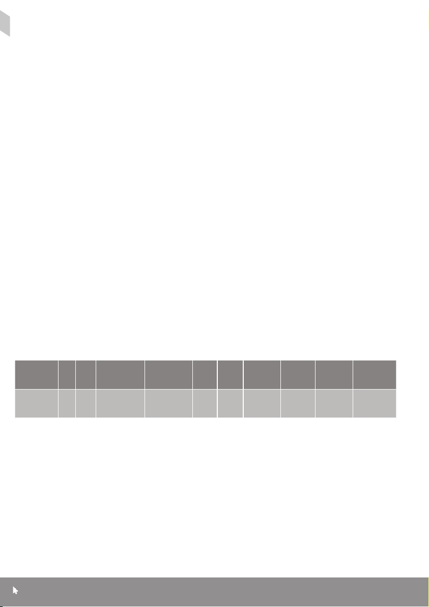
Specications
Booster In Out
27822BMR
SLx2 IR
1 2 87-790MHz
Frequency
VHF Signal
UHF Signal
Philex reserve the right to modify their designs or specications, In the light of future
developments, without prior notice. Performance gures quoted are typical and subject to
normal manufacturing and service tolerances.
Support:
www.slxtechnology.com/support
Suitable
for
FM/DAB/
TV C h21- 6 0
Freeview
Noise
Typ.
Isolation
Out/Out
Gain
17d B <3dB 12 dB 94dBµV
5
Max
Output
IR
Bypass
5-30MHz
+3dB
IR Power
9VDC
15m A S SP
Page 6
Technical Support
If you experience problems setting up your
aerial, please visit our technical website at
www.slxtechnology.com/support you can
send us a message or live chat during ofce
hours.
Declaration of Conformity
Hereby, Philex declares that this booster/
amplier for TV broadcast reception in
domestic premises is in compliance with the
Radio Equipment Directive 2014/53/EU.
The full Declaration of Conformity is available
by contacting the following internet address:
www.slxtechnology.com/DoC
COMPLIANT
Standard: EN 303 354
Product Type: D Signal Distribution Amplier
Suitable for digital TV signal distribution
Ch21-60 from a receiver or from an aerial
tted with a 4G lter in the UK and EIRE.
Waste electrical and electronic
products should not be disposed of
with household waste. Please recycle
where facilities exist. Check with your
Local Authority for recycling advice.
Wall Mounting Drilling Template
Prepare holes with centres 50mm apart
Support:
www.slxtechnology.com/support
SLx2B
for wall mounting
© Philex Electronic Ltd 2017. v1 MK42 0NX
6
 Loading...