

Page 1
PHOTO
s s
o<
FACT*
with
Folder
ClRCUIIRACE*
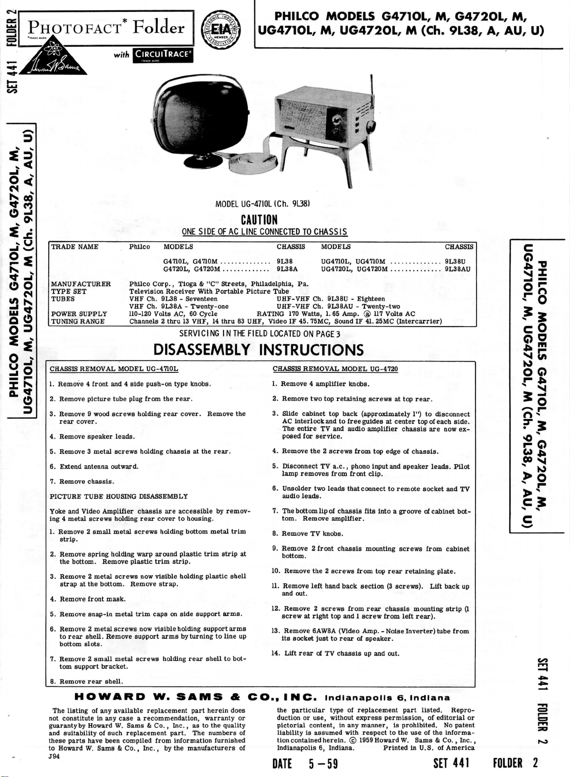
MODEL
UG471OL,
UG-47IOL
PHILCO
(Ch.
9L38)
MODELS G471OL,
M,
UG472OL, M (Ch.
M,
G472OL,
9L38,
A,
AU, U)
M,
<fr
-I
Is-
o o
<N
</}
N
w
*
So
03
8-
y
o
o
D
-
Philco
Philco
VHF
MODELS
Corp.,
Ch.
TRADE
NAME
MANUFACTURER
TYPE
SET
TUBES
POWER
TUNING
Television
VHF Ch.
SUPPLY 110-120 Volts
RANGE
Channels 2 thru
DISASSEMBLY
CHASSIS
REMOVAL
1.
Remove 4 front
2.
Remove picture tube plug from
3.
Remove 9 wood
rear
cover.
4.
Remove speaker
5.
Remove 3 metal
6.
Extend antenna outward.
7.
Remove
PICTURE
Yoke
ing 4 metal
1.
2.
3.
4.
5.
6.
7.
not
guaranty
and
these
to
J94
TUBE
and
Video Amplifier
Remove 2 small
strip.
Remove spring holding warp around
the
bottom. Remove
Remove 2 metal
strap
at the
Remove front
Remove snap-in
Remove 2 metal
to
rear
shell.
bottom
slots.
Remove 2 small
tom
support
8.
Remove
HOWARD
The
listing
constitute
by
suitability
parts
Howard
W.
MODEL
and 4
side
screws
holding
leads.
screws
holding
chassis,
HOUSING
screws
bottom. Remove
mask.
Remove support
bracket.
rear
shell.
of any
in any
Howard
of
have been compiled
Sams & Co.,
DISASSEMBLY
chassis
holding
rear
metal
screws
plastic
screws
now
metal
trim
screws
now
metal
screws
available replacement
case a recommendation, warranty
W.
Sams
such replacement part.
Inc.,
UG-4710L
push-on type knobs.
cover
trim
visible
caps
visible
W.
& Co. ,
from
CAUTION
ONE
SIDE
OF AC
LINE
CONNECTED
CHASSIS
G4710L,
G4710M
G4720L,
Tloga & "C"
Receiver With
9L38 - Seventeen UHF-VHF
9L38A - Twenty-one UHF-VHF
AC, 60
13
SERVICl
9L38
G4720M
9L38A
Streets,
thru
IN
THE
Philadelphia,
Picture
83
UHF,
Fl
ELD
Portable
Cycle RATING
VHF,
14
NG
Tube
170
Video
LOCATED
Pa.
IF 45.
INSTRUCTIONS
CHASSIS REMOVAL MODEL UG-4720
1.
Remove 4 amplifier
2.
the
rear.
rear
cover.
chassis
at the
are
accessible
to
housing.
holding bottom
plastic
strip.
holding
strap.
on
side
support
holding support
arms
by
turning
holding
rear
SAMS
part
Inc.
, as to the
The
information
by the
manufacturers
Remove
rear.
by
remov-
metal
trim
trim
strip
plastic
shell
arms.
arms
to
line
shell
to
&
herein does
quality
numbers
furnished
the
at
up
bot-
CO.,
or
of
of
Remove
3.
Slide
cabinet
AC
interlock
The
entire
posed
4.
Remove
5.
Disconnect
lamp
removes
6.
Unsolder
audio
7.
The
bottom
tom. Remove amplifier.
8.
Remove
9.
Remove 2 front
bottom.
10.
Remove
11.
Remove left hand back
and
out.
12.
Remove 2 screws
screw
13.
Remove
its
socket
14.
Lift
rear
INC. Indianapolis
the
particular
duction
pictorial
liability
tion
contained herein. © 1959 Howard
Indianapolis 6, Indiana.
DATE
5-59
TO
CHASSIS
MODELS
UG4710L,
UG4720L,
Ch.
9L38U - Eighteen
Ch.
9L38AU - Twenty-two
Watts,
1. 65
75MC, Sound
ON
two top
for
the 2
leads.
TV
at
or
content,
is
Amp. @ 117
PAGE
3
retaining
top
back
and to
TV and
service.
screws
TV
a.c.,
from front
two
leads
lip
of
chassis
knobs.
chassis
the 2
screws
right
top and 1
6AW8A
(Video
just
to
rear
of TV
chassis
type
use, without
in any
assumed
with
UG4710M
UG4720M
IF
knobs.
free
audio
from
phono
that connect
from
of
of
express
9L38U
9L38AU
Volts
41.
screws
(approximately
guides
amplifier
top
input
clip.
fits
mounting
from
section
rear
screw
Amp.-NoiseInverter)tube
speaker.
up and
replacement
manner,
respect
Printed
AC
25MC
(Intercarrler)
at top
at
center
chassis
edge
of
and
speaker
to
remote
into a groove
screws
top
rear
retaining
(3
screws).
chassis
from left
out.
6,
part
permission,
is
prohibited.
to the use of the
W.
1") to
chassis.
mounting
Indiana
Sams & Co.,
in U.S. of America
rear.
disconnect
top
of
are now ex-
leads.
socket
of
cabinet bot-
from
Lift back
rear).
listed.
of
SET
CHASSIS
each
side.
Pilot
and TV
cabinet
plate.
strip
from
Repro-
editorial
No
patent
informa-
441
up
(1
or
Inc.,
FOLDER
Is
e
o o
r
•**
*
-
J
o
"o
•!"
?•$
?e
««
>
C
2
Page 2
SOUND
©3AU6
IF
TOR80.
1704
JUNCT
BO
PICTURE
TERMINAL
HV
LEAD
TUBE
#17
©S3.3meg
JUMPER
CABLE
CHASSIS
GUIDE
SW
ON
VOLUME
ON
115V
9L38A
SWITCH
ONLY
1000 1 IjBUIZ
mml_L'
60001W
,ffi\
l^
39000
PAGE
DC
COIL
RESISTANCE
NOT
SHOWN
ON
SCHEMATIC DIAGRAM
(CONTROL
TO
SIGNAL
1
DC
voltmeter;
per
bottom
VIEWED
TAKEN
PRODUCE
AT
voltage
AC
volt.
of
socket
®
Howard
50
PICTURE TUBE
measurements
voltage
W.
WAVEFORMS
SET
PEAK
A
PHOTOFACT STANDARD
2
TO
TERMINALS 3 &d
OF
TUNER
POWER
4
VALUES UNDER
FROM SHAFT
WITH
VOLTS PEAK-TO-
measured
5
Sams & Co.,
CONTROLS
GRID
taken with
vacuum
at
NOTATION
Inc.
ONE OHM
END)
1000
ohms
SCHEMATIC
1959
tube
3.
unless
SOCKET
Meosured
4.
Line Voltage
All
controls
3000CJ10W
ADDITIONAL
SCHEMATICS
TUNER
76-I1547-8IT-69K)
VHF
with
UHF
provisions
CH.
9L38A.AU.18
TO
TERMI
OF
TUf€R
SOCKET
5
VHF..
UHF..
TUNER76-11450-7IT-68G)
TUNER76-10391-1IT-Z7FI
ALT.
CIRCUITS
oth
PAGE
7
16
NAL
5
POWER
VC3
NUMBERS
ASSIGNED
TRANSFORMERS
PONENT
REPLACEMENT
THE
UNIT.
,
,.
/
16VAC I 22VAC V 27VAC
/
ilOOOmmf
TO
COILS,
SWITCHES,
ARE TO
FACILITATE
AND MAY NOT
PLUGS,
CIRCUIT
NECESSARILY
SOCKETS,
TRACING
BE
OR
FOUND
AND
COM-
ON
Page 3
UDIO
S)
OUTPUT
5AQ5
TAKEN
TUBE
AND
HEIGHT
AT
CENTER
WITH
(V10A)
PIN 6 OF
SHORTED
CONTROL
OF
ROTATION.
VERT
TO
(R3B)
MULT
GROUND,
SET
TO
PICTURE
MOUNTING
TUBE
BAND
PHILCO
UG471OL,
MODELS
M,
G471OL,
UG4720L, M (Ch.
M,
G472OL,
9L38,
A,
M,
AU,
16
15
REMOTE
PICTURE
w
CONNECTOR
U)
PAGE
TUBE
19
Page 4
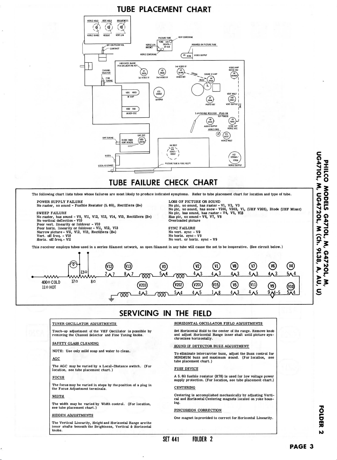
The
This
POWER
No
SWEEP
No
No
Poor
Poor
Narrow
Vert,
Horlz.
following
raster,
raster,
vertical
receiver
chart
lists
SUPPLY FAILURE
no
sound - Fusible
FAILURE
has
sound
deflection
vert,
linearity
horlz.
linearity
picture
- VU,
off
freq. - V10
off
freq.-
VU
employs
HORIZ
HOLD
HOHIZ
RANGE
/
.
H
— 1 1
NDICATIS
f— C P N OH
1
1
CHANf€L
tubes
whose
failures
Resistor
- V9,
VU,
V12, V13,
- V10
or
foldover - V10
or
foldover
V12,
tubes
- VU,
V13, Rectifiers
used
in a
VERT
HOLD
BRIGHTUSS
HEIGHT
VEST
LIN
OFF-ONIPUSHI-VOL
FTx-
CONTRAST
v-p,
SELECTOR
UaZi)
L
FINE
1st
&.«
1!
I
UHF
TUNING
/^\
LOCAL-DISTANCE — '
j-f
•••
TUBE
are
(5.
6ft),
V14,
V12,
V13
(B+)
series
fUament
TUBE
PLACEMENT CHART
PICTURETUBE ^ VtRT
CENTERING
YOKE
VIS
C
IZ
LIN
J1EAPJ/
w
LOCAT
"vaY
HO
BLANK
NG
KEYv
VI
DEO
1
JflcaJ
Rf
AMP
M1XER-OSC
LHFOSC
c:::
\E
"
WtRlr*G
INB2A I W03
MOUNTED
^o1'""
/,
C W
,^r\F
^
2nd
VIDEO
^
I
I!04GT j \^_^^
DAW
{^}-
\—
_
PICTURE
/^
HORIZ
JCB6
»"sr
^-^fflS.
IF
VIDtO
DO
~- ^ -^(^vT^
rt§b
ni*,MixEfii
\w«y
HVRECT
>5u^
'
1G3GV
\
'"GT
y
\
12D06A/
]
TL8E 4 YOKE
RECPT
V
FAILURE CHECK CHART
most
likely
to
produce
indicated
symptoms. Refer
LOSS
OF
Rectifiers
V15,
Rectifiers
network,
(B+)
an
(B+)
open
filament in any
No
pic,
no
No
pic,
no
No
pic,
has
Has
pic,
no
Overloaded
SYNC
FAILURE
No
vert,
sync
No
horlz.
No
vert,
or
tube
PICTURE
sound,
sound,
sound,
sound-
picture
sync
horiz.
will
ON
PICTURE
TUflt
1
VIDEOOUTPUT
s™»,f,»
VERT
5.60FUSIBII
/
^\l"""'^vj
/f
Q^>
//
AUDIO
//
HORIZ
/'vi!
has
has
has
- V9
- V9
sync
cause
(2J
N^
MULT
(S)
RESISTOR
IPLUG-INJ
(i>J
OUTPUT
SYNC
FREO
HORIZAfC
^(S)
HORIZ
—
to
tube placement
OR
SOUND
raster - VI,
snow - V201, V202,
raster
- V4, V5, V15
V6, V7, V8
- V9
the set to be
S
SEP
MULT
L
nmJ
-•'
OUIPU1
chart
V2, V3
VI,
inoperative. (See
A
for
(UHF
location
V203),
circuit
and
type
Diode
below.)
of
tube.
(UHF
^
Mixer)
UG471OL,
M
>
>
K)
o
o
r-
*>
k-
*
00
s^
Q
o
PHILCO
f
2
O
4000
COLD
lln
HOT
TUNER
Touch-up
removing
SAFETY
NOTE:
AGC
The AGC may be
location,
The
the
The
see
HIDDEN
The
inner
knobs.
l?n
OSCILLATOR
adjustment
the
Channel
GLASS
Use
only mild soap
see
tube placement
focus
may be
Focus
Adjustment
width
may be
tube placement
ADJUSTMENTS
Vertical
Linearity,
shafts beneath
80
ADJUSTMENTS
of the
VHF
Selector
Oscillator
and
Fine Tuning knobs.
CLEANING
and
water
to
varied
by a
Local-Distance
chart.)
varied
in
steps
terminals.
varied
chart.)
the
by the
by
Width
control.
Height
and
Horizontal Range
Brightness, Vertical & Horizontal
SERVICING
is
possible
by
clean.
switch.
(For
position
of a
plug
in
(For
location,
are
the
IN THE
HORIZONTAL
Set
Horizontal
and
adjust
chronizes
SOUND
To
eliminate
MINIMUM
tube
placement chart.)
FUSE
DEVICE
A
5.
6Si
supply
protection.
CENTERING
Centering
cal and
ing.
PINCUSHION
One
magnet
SET
441
FOLDER
4A3
4A3
4A3
4A3
FIELD
OSCILLATOR FIELD ADJUSTMENTS
Hold
to the
center
Horizontal
horizontally.
IF
DETECTOR
intercarrier
buzz
fusible
resistor
is
accomplished
Horizontal
CORRECTION
is
provided
and
maximum sound. (For
(For location,
Centering
2
of its
Range inner shaft until picture syn-
BUZZ
ADJUSTMENT
buzz, adjust
(R78)
is
used
see
mechanically
magnets
to
correct
for
4A3
4A5
range.
the
Buzz control
for low
tube
placement
by
located
Horizontal
4A3 5A4
9A4-5
Remove knob
location,
adjusting
for
see
voltage power
chart.)
Verti-
on
yoke
hous-
Linearity.
5A4
PAGE
O
5
3
K>
3
Page 5
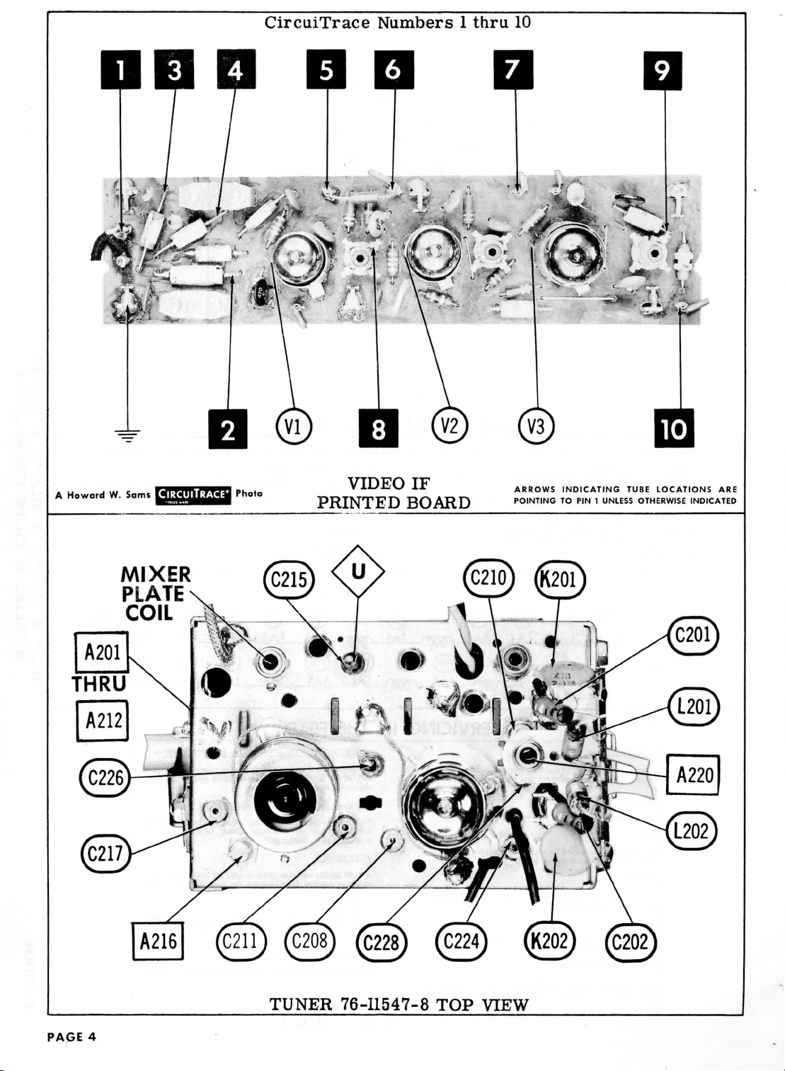
CircuiTrace
Numbers 1 thru
10
0
A
Howard
W.
A201
Sams
MIXER
PLATE
COIL
Photo
VIDEO
PRINTED
IF
BOARD
ARROWS
POINTING
INDICATING
TO PIN 1
UNLESS OTHERWISE
TUBE
LOCATIONS
INDICATED
ARE
PAGE
TUNER
4
76-11547-8
TOP
VIEW
Page 6
UHF
F 1 NPUT
f
:k-
A
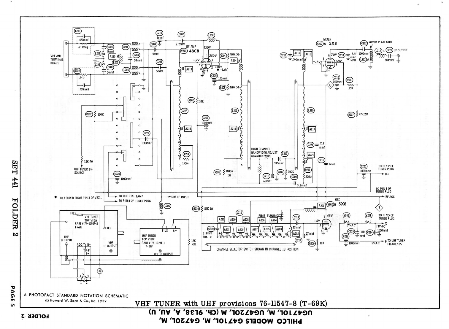
PHOTOFACT STANDARD
@Howordw-5c"1s&c°-'nc-1959
PART*
76-11547-8
T-69K
AGCH
B+
B+
1 1 1
1
|
j
4^3
NOTATION
iFILS
VHF
IF
OUTPUT
©
_^
SCHEMATIC
VHF
€Z
UHF
TUNER
TOP
VIEW
PART*
76-10391-1
T-27F
UHF
-
-*_,
TUNER
(n
ynv
A A
FILS 8 +
©
IF
OUTPUT
'v
'W
'lOCZfrO
<
with
'8ci6
CHANNEL SELECTOR SWITCH SHOWN
UHF
provisions 76-11547-8
'HD) w 'loc/fron
7W
y10LZfr9
S13QOW
HIGH CHANNEL
BANDWIDTH
GIMMICK
WIRE
IN
yw
ADJUST
CHANNEL
13
POSITION
'
ODIIHd
(T-69K)
—
^
-T
lOOOmmf
2VAC
p
TO
UHF
FILAMENTS
TUNER
Page 7
ITEM
No.
V201
V202
ITEM
No.
C201
C202
C203
C204
0205
C206
C207
C208
C209
C210
C211
C212
C213
C214
C215
C216
C217
C218
C219
C220
C221
C222
C223
C224
C225
C226
C227
C228
C229
C230
C231
C232
C233
C234
C235
ITEM
No.
R201
R202
R203
R204
R205
R206
R207
R208
ITEM
No.
L201
L202
L203
L204
L205
L206
L207
L208
L209
L210
K201
K202
ITEM
M201
ITEM
No.
No.
RF
Amp.
Mixer-Osc.
RATING
CAP.
VOLT
5
5
39
5
5
1000
2.2
150
3.9
5
65
330
.5-3
7.5
150
1.0
27
27
3.9
1000
2.2
1000
680
1000
150
1000
330
1000
.68
30
15
.5-3
250
1000
1000
RATING
OHMS
isoon
10K
470K
5%
470K
5%
leoon
100 K
47K
15K
USE
RF
Choke
RF
Choke
IF
Trap
VHF
Ant.
VHF
Ant.
RF
Choke
Ant.
Colls
Cathode
Choke
RF
Colls
MLxer
Grid
Colls
Antenna
Antenna
ORIG.
TYPE
1N82A
TUNER
TUBES
USE
PHILCO
PART
30-1224-78
30-1224-78
62-039409011
30-1224-78
30-1224-78
30-1268-7
30-1221-6
30-1268-6
30-1221-14
30-1268-5
30-1268-2
30-1265-2
31-6520-25
30-1251-19
30-1268-6
30-1224-82
30-1268-4
30-1224-146
30-1221-14
30-1268-7
30-1224-143
30-1238-13
30-1238-22
30-1268-7
30-1265-3
30-1268-7
30-1265-2
30-1268-7
30-1221-11
76-10170
30-1224-133
31-6520-1
30-1261
30-1258
30-1258
PHILCO
PART
WATT
66-2158340
66-3108340
66-4478240
66-4478240
1
66-2184340
66-4108340
66-3475340
2
66-3158340
PHILCO
PART
32-4645-37
32-4645-37
32-4719-2
Trans.
32-4725
Trans.
32-4725
32-4726-10
76-10112
32-4652-51
328-0116
76-10110
USE
Isolation
Network
Isolation
Network
PHILCO
PART
No.
34-8027
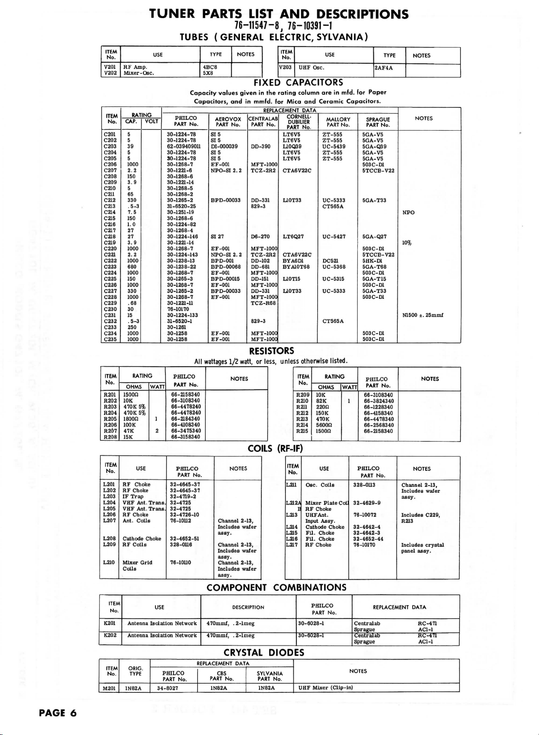
PARTS
(GENERAL
TYPE
4BC8
5X8
Capacity
Capacitors,
No.
SIS
SI
DI-000039
SIB
SIS
EF-001
NPO-SI
BPD-00033
SI 27
EF-001
NPO-SI
BPD-001
BPD-00068
EF-001
BPD-00015
EF-001
BPD-00033
EF-001
EF-001
EF-001
76-11547-8,
values
and in
AEROVOX
PART
No.
5
2. 2
2. 2
LIST
NOTES
FIXED
given
mmfd.
CENTRALAB
PART
DD-390
MFT-1000
TCZ-2R2
DD-331
829-3
D6-270
MFT-1000
TCZ-2R2
DD-102
DD-681
MFT-1000
DD-151
MFT-1000
DD-331
MFT-1000
TCZ-R68
829-3
MFT-1000
MFT-1000
AND
76-10391-1
ELECTRIC,
ITEM
No.
V203
CAPACITORS
in the
rating column
for
Mica
REPLACEMENT
CORNELL-
DUBIUER
No.
PART
LT6V5
LT6V5
L10Q39
LT6V5
LT6V5
CTA6V22C
L10T33
LT6Q27
CTA6V22C
BYA6D1
BYA10T68
L10T15
L10T33
RESISTORS
All
wattages
1/2
watt,
or
less,
unless otherwise listed.
No.
No.
NOTES
COILS
NOTES
Channel
2-13,
Includes
wafer
assy.
Channel
2-13,
Includes wafer
assy.
Channel
2-13,
Includes wafer
assy.
(RF-IF)
ITEM
No.
L211
L212A
L213
L214
L215
L216
L217
COMPONENT COMBINATIONS
DESCRIPTION
470mmf, . 2-lmeg
470mmf, . 2-lmeg
CRYSTAL
REPLACEMENT
CBS
PART
No.
1N82A
DATA
DIODES
SYLVANIA
PART
No.
1N82A
DESCRIPTIONS
SYLVANIA)
USE
UHF
Osc.
are in
and
Ceramic Capacitors.
DATA
MALLORY
PART
No.
ZT-555
ZT-555
UC-5439
ZT-555
ZT-555
UC-5333
CT565A
UC-5427
DC521
UC-5368
UC-5315
UC-5333
CT565A
ITEM
RATING
No.
OHMS
R209
10 K
R210
82 K
R211
220SJ
R212
150K
R213
470K
R214
5600J!
R215
isoon
1
USE
Osc.
Colls
Mixer
Plate
E
RF
Choke
UHF
Ant.
Input
Assy.
Cathode
Choke
Fil.
Choke
Fil.
Choke
RF
Choke
PHILCO
PART
No.
30-6028-1
30-6028-1
UHF
Mixer
(Clip-in)
mfd.
No.
WATT
Col
2AF4A
for
Paper
SPRAGUE
PART
No.
5GA-V5
5GA-V5
5GA-Q39
5GA-V5
5GA-V5
503C-D1
5TCCB-V22
5GA-T33
5GA-Q27
503C-D1
5TCCB-V22
5HK-D1
5GA-T68
503C-D1
5GA-T15
503C-D1
5GA-T33
503C-D1
503C-D1
503C-D1
PHILCO
PART
No.
66-3108340
1
66-3824340
66-1228340
66-4158340
66-4478340
66-2568340
66-2158340
PHILCO
PART
No.
328-0113
32-4629-9
76-10072
32-4642-4
32-4642-3
32-4652-44
76-10170
REPLACEMENT
Centralab
HC-471
Sprague AC1-1
Centralab
RC-471
Sprague AC1-1
NOTES
TYPE
NOTES
NOTES
NPO
10%
N1500
NOTES
Channel
Includes
assy.
Includes
R213
Includes
panel
assy.
DATA
±.25mmf
NOTES
2-13,
wafer
C229,
crystal
PAGE
6
Page 8

w
H
CA5
CD
O
o
MIXER
PLATE COIL
IF
OUTPUT
5X8
4BC8
4A5
. 5
CHANNEL
SELECTOR
A
PHOTOFACT STANDARD
•o
o
m
S
©
Howard
W.
NOTATION
Sams
8.
Co., Inc.
SCHEMATIC
1959
(n
ynv
yv
VHF
'
TUNER
SWITCH SHOWN
76-11450-7
w
'icczfron
IN
CHANNEL
(T-68G)
'w
S13QOW
13
POSITION
'
ODIIHd
O TO
FILAMENT
STRING
Page 9

TUNER
ALIGNMENT
INSTRUCTIONS
PRE-ALIGNMENT
USE
AN
ISOLATION
The
high
voltage
Allow
a 20
Suggest
VHF
The
Set the
Use
This procedure
DUMMY
ANTENNA
Two
Carbon
Resistors
VHF
Connect
Detune
Connect
Use
Use
DUMMY
ANTENNA
Two
Carbon
Resistore
minute
alignment
OSCILLATOR
signal
generator
Fine
Tuning
only
enough
Across
120!J
terminals
in
RF AND
the
negative
Mixer
the
synchronized sweep voltage
only
enough
10MC sweep
Across
120J2
terminals
each
"
"
"
11
INSTRUCTIONS
TRANSFORMER
lead
should
warm-up
tools : A201 thru
ALIGNMENT
output
to the
center
signal
generator
uses
the
traps
SIGNAL
GENERATOR
COUPLING
VHF
antenna
with
each
MIXER
Plate
lead.
120B
lead.
ALIGNMENT
lead
of a 1. 5
Coil
by
sweep generator
unless
otherwise
SWEEP
GENERATOR
COUPLING
VHF
antenna
with
120JJ
"
"
TO
be
period
lead
of the
connecting
in
PROTECT
securely
taped
for the
receiver
A212
A213
thru A215 General Cement
A216
General
A217,
A218,
A219
General Cement
A220
General Cement #8282,
should
be
of its
terminated
range.
output
to
provide a usable indication
Video
SIGNAL
GENERATOR
FREQUENCY
209.
75MC
(400^,
50%
AM
Mod)
203.
75MC
197.75MC
191.
75MC
185.75MC
179.
75MC
173.
75MC
81.
75MC
75.75MC
65.75MC
59.
75MC
53.75MC
volt
bias
a 10 to
from
output
to
noted.
SWEEP
GENERATOR
FREQUENCY
213 MC
"
177MC
213 MC
85MC
85 MC
Not
used
THE
and
kept away
and
General
Walsco
Walsco
Walsco
A221.
. .
General Cement
Walsco
Walsco
Walsco
with
IF
strip.
They
CHANNEL
13
12
11
10
9
8
7
6
5
4
3
2
supply
to
point
20mmf
capacitor
the
sweep
provide a usable pattern
MARKER
GENERATOR
FREQUENCY
211.
25MC
215.75MC
"
175.25MC
213 MC
85 MC
83.25MC
87.
75MC
43.
SMC
(400%
AM
Mod)
TEST EQUIPMENT.
from
the
test
equipment.
#2520,
Cement #5000, 5003, 5004,
#2515,
#2525
#2542,
#2543,
its
must
<£> . Positive
generator
chassis.
Cement
#5097
or
#9291
2522
2520,
2522,
#5000,
5003,
#8606,
8606L
2543
or
2544
8606,
2544,
2545
characteristic
on
scope.
be in
proper alignment before attempting
CONNECT
SCOPE
Across
Video
Detector
load.
to the
on
to
it
temporarily.
horizontal
scope.
Vert. Amp. thru
10K
Low
across
CHANNEL
13
"
7
13
. 6
4
30%
8727
5008,
2525
or
2537
8276,
8290
or
9091
8606L
or
9295
impedance, usually
ADJUST
A201
A202
A203
A204
A205
A206
A207
A208
A209
A210
A211
A212
chassis.
input
of the
CONNECT
SCOPE
to
point
<§>
to
chassis.
.
side
"
"
"
"
5009,
8276
or
8609
50
ohms.
Adjust
oscilloscope
ADJUST
A213
A214
A215
A216
A217,
A218,
A219
A220
or
9291
to
align
for
MINIMUM
for
horizontal deflection.
Adjust
of
response
markers
,
Adjust
of
response
markers
marker
Adjust
as in
effect
Retouch
symmetrical
marker. Repeat
until
optimum response
channels
Turn
A217
peak
appears.
to
allow
until
peak falls
sary
to
Adjust
symmetry
Retouch
similar
Adjust
the
oscillator.
REMARKS
4001,
indication.
REMARKS
for
maximum gain
similar
as
shown.
for
maximum
similar
as
shown.
positions,
to
obtain
Fig.
202 to
of
channel
A214
and
response centered
7 and 13.
counterclockwise until a single
(DO NOT
the
core
at
increase sweep generator
A219
for
maximum amplitude
of
single peak.
A217
and
to
Fig. 203.
for
MINIMUM
and
to
Fig.
201
gain
and
to
Fig.
201
Adjust
A215
correct
compensate
13.
A215 SLIGHTLY
steps
to
85MC.
A218
A214
for
proper
tilt
on top of
4 and 5
is
obtained
unscrew
fall
out. ) Adjust
(It may be
for
response
scope indication.
symmetry
with
symmetry
with
to set
tilt.
for the
tuning
for
about
alternately
on
far
A218
neces-
output.)
and
curve
enough
PAGE
8
CONTINUED
PAGE
13
Page 10

PRE-ALIGNMENT
USE
AN
ISOLATION TRANSFORMER
The
High Voltage
Allow
a 20
Suggested
VI
DEO IF
Connect
Connect
The
sweep
Use
only
DUMMY
ANTENNA
Direct
..
Two
120S2
Carbon
Resistors
4.5MC
The
detector used
Adjust
DUMMY
ANTENNA
.OOSmfd
SOUND
Tune
in a
alignment.
Connect
Disconnect
Connect
lead
minute warm-up
alignment
ALIGNMENT
the
negative
the
synchronized sweep
generator
enough
sweep generator
GENERATOR
High
side
tube
shield
Mixer-Osc.
Low
side
Across
antenna
nals
with
lead.
TRAP
ALIGNMENT
the
slug
for
GENERATOR
High
side
Low
side
IF
ALIGNMENT
weak
station
the
antenna
antenna.
antenna. Retouch
INSTRUCTIONS
should
be
securely
period
tools:
lead
output
SWEEP
COUPLING
to
ungrounded
floating over
tube
to
chassis.
ii
120S2
in
in
alignment
maximum deflection.
SIGNAL
COUPLING
to
point
to
chassis.
signal
for a
Adjust
for the
Al
A5
of a 4.5
volt
voltage
lead
should
output
(V202).
termi-
each
of the 4.
<Sj>
.
(antenna disconnected)
strong
signal.
A10,
All and
A9 for
maximum sound.
ALIGNMENT
TO
PROTECT
taped
receiver
thru
A4
thru
A12, & Mixer
bias
from
be
to
SWEEP
GENERATOR
FREQUENCY
Not
used.
11
ii
69MC
(10MC
Swp)
SMC
SIGNAL
GENERATOR
FREQUENCY
4.
SMC
(400%
AM
Mod)
Adjust
A12
THE
and
General Cement #5004, 5008,
supply
the
terminated
provide a usable
trap
30%
A9 for
for
TEST
kept away from
and
test
Plate
to
point
sweep
generator
with
MARKER
GENERATOR
FREQUENCY
45.75MC
(400%
30%
AM
Mod)
41.25MC
(Crystal
Accuracy)
47. 4MC
(Crystal
Accuracy)
45.0MC
42. 7MC
45.
75MC
43.85MC
65.75MC
42. 7MC
43.85MC
45.0MC
45.75MC
must
first
CHANNEL
Any
non-
interfer-
ing
channel
and
adjust
maximum
maximum
equipment.
Coil
<^> . Positive
its
pattern
be
sound.
INSTRUCTIONS
EQUIPMENT.
the
chassis.
Walsco
Walsco
to
horizontal
impedance,
scope.
Vert.
to
point
side
(Across
or
load).
by
connecting
VTVM
detector
2) to
tube
Common
picture.
Use
peak furthest
#2520
#2543, 2544
chassis.
CONNECT
Amp.
to
cath-
Do not
General Cement #8282, 8606,
to the
characteristic
on
CHANNEL
4
ii
"
"
11
"
padded
CONNECT
DC
probe thru
probe (Fig.
ode
of
picture
(point
^>).
to
chassis.
for
best
sound.
input
of the
usually
SCOPE
thru
<^>
. Low
chassis.
video
detect-
"
||
»
..
to an
ADJUST
A8
change
counterclockwise.
or
2545
oscilloscope
10K
accurate
setting
or
5009
8606L
50
ohms.
ADJUST
Mixer
Plate
Coil
Al
A2,
A3
Mixer
Plate
Coil
A4.A5
A6
A7
Fine
Tuning
source
of 4. 5MC and a
Adjust
for
of
Fine Tuning during
or
9295
for
horizontal
Use
only enough
a
usable
indication
Adjust
for
maximum deflection.
Increase
generator
MINIMUM
Increase
MINIMUM
2
Use
vide a usable
Adjust
scope.
Adjust
indication
Fine Tuning during
Check
necessary,
set
A5
curve
MINIMUM
and 3.
only
for
Fine
for
carrier
and A4 to
and A6 to
400% Indication.
generator
400%
enough
maximum
Tuning
on
scope.
response
retouch
level,
adjust
REMARKS
deflection.
deflection.
REMARKS
generator
output. Adjust
output. Adjust
indication.
generator
indication
400%
..
for
DO NOT
balance
similar
Mixer
A7 to
low
adjust
VTVM
to the
balance
output
to
for
Repeat
steps
output
to
indication
MINIMUM
frequency
high frequency
of
Plate
adjust
output.
of
400%
change
alignment.
to
Fig.
Coil
curve
slope
provide
for
pro-
on
1.
If
to
limit,
side.
o
4*
-O
N
I
oS
r
o
ss
=
g
2s
•fc
r-
\
tn
of
O
Jk
00
SJ
"
tO
> O
F
IG.I
0
If
0
It
INPUT
SET 441
PHILCO
PART
OR
EQUIVALENT
pL
2
4.5MC
.
1.2mmf
FIG
FOLDER
132-4449
j
2.
2
^i
1N60
.OOlmfd
A A A Q
4.7K
L TO
r
VTVM
-
PAGE
o
3
9
Page 11

VI
V4
V5
V6
V7
ITEM
07
C8
C9
CIO
Cll
C12
C13
C14
CIS
C16
C17
CIS
C19
C20
C21
C22
C23
C24
C25
C26
C27
C28
C29
C30
C31
C32
C33
C34
C35
C36
C37
CSS
C39
C40
C41
C42
C43
C44
C45
C46
C47
C48
C49
C50
C51
C52
C53
C54
C55
C56
C57
C58
C59
C60
C61
C62
ITEM
No.
V2
V3
ITEM
No.
V15
ITEM
Cl
C2A
C3A
C4
C5
C6
No.
No.
B
C
D
B
3)
3) Not
*Not
1st
Video
2nd
Video
3rd
Video
Vldeo
Video Amp.
Video Output
Sound
Audio
PHILCO
PART
21EAP4/
SF-21A
RATING
CAP.
150
.140
•100
120
20
.20
•10
200
C
4
25
20
*
Not
D
Some
Alternate
Alternate
CAP.
.15
3.3
.5-3
.5-3
1-5
1-5
1000
680
470
1000
680
27
680
1000
S
.033
68
.0068
.22
.022
10
7.5
2200
4700
1000
1000
1000
10
8200
4700
.22
.1
.0033
.0015
.033
.068
.0039
390
.1
10000
250
.022
82
22
470
22
470
1000
1000
1500
1000
470
1000
.1
.22
.01
versions
)
Runs 2 thru
Not
used
used
normally
IF
IF
IF
Del.
IF
Amp.
Det.
No.
VOLT.
200
350
300
300
300
300
450
25
300
25
300
normally
versions
RATING
VOLT
200
200
600
400
400
1000
100
400
400
1000
400
200
200
200
3000
400
3000
600
200
600
4 use
in
some
in
Ch.
in
TUBES
USE
Amp.
Amp.
Amp.-
-Noise
Inv.
GENERAL
PART
PHILCO
PART
30-2568-75
30-2590-40
30-2590-46
30-2596-3
30-2417-9
30-2417-18
In
distributor's
may use
Part
#30-2417-60.
Part
#30-2417-44.
Capacity
Capacitors,
TOL
NPO5%
10%
10%
10%
N330
10%
10%
10%
may use
2700mmf
320mmf®
versions.
9L38,
A.
distributor's
(GENERAL
TYPE
3BZ6
3BZ6
5AM8
6AW8A
3CB6
3AU6
3BN6
REPLACEMENT
ELECTRIC
No.
ELECTROLYTIC
No.
(J>
AFHS4-56-
@
®
stock.
140mfd ® 200V
Combined with
Combined with
values
and in
PHILCO
PART
30-4650-48
30-1263-38
31-6535-1
31-6535-1
31-6535-2
31-6535-2
30-1238-3
30-1262-15
30-1238-10
30-1238-3
30-1262-15
30-1263-6
30-1262-15
30-1238-3
30-1263
30-4650-44
30-1263-4
30-4650-57
30-4650-49
30-4650-43
30-1221-25
30-1263-37
30-1262-2
30-1262-13
30-1262-13
30-1262-13
30-1263-36
30-1262-1
30-1269-3
30-4681-6
30-4650-47
30-4651-14
30-4650-87
30-4650-44
30-4650-46
30-4651-25
30-1264-1
30-4650-47
30-1238-2
30-1246-23
30-4650-43
30-1246-10
30-1238-10
30-1238-10
30-1238-3
30-1238-3
30-1262-9
30-1238-3
30-1262-16
30-1238-3
30-4650-64
30-4678-49
30-4650-58
in
this
3000V
in
stock.
Available
NOTES
PICTURE
DATA
RCA
PART
AEROVOX
PART
No.
AFHS1-23
94.9
PRS350V4
PRS25V25
PRS450V20
Available thru
with
FIXED
given
mmfd.
No.
application
this
applicaton
thru
ELECTRIC,
ITEM
TUBE
No.
21EAP4/
SF-21A
CAPACITORS
REPLACEMENT
CORNELL-
DUBILIER
PART
No.
XA0261
C1150
BR435
BBR25-25
BR2035
distributor
same
part number.
C6 in
late
production
C5 in
late
production
CAPACITORS
in the
rating column
for
Mica
REPLACEMENT
CENTRALAB
AEROVOX
PART
No.
(Part
#30-1262-7).
(Part
distributor
PART
DTZ-3R3
829-3
829-3
829-6
829-6
DD-I02
DD-681
MD-471
DD-102
DD-681
MD-270
DD-681
DD-102
MD-050
DD-680
MD-100
DD-7R5
DD-222
DD-472
DD-102
DD-102
DD-102
TCA-10
DD-822
DD-472
DF-104
DD-152
DF-104
DD-103
DD30-251
DD30-820
DD-220
DD-471
DD-220
DD-471
DD-102
DD-102
DD-152
DD-102
DD-471
DD-102
DF-104
D6-103
#30-1246-24).
P288N-15
NPO-DI3.3
BPD-001
BPD-00068
DI470
BPD-001
BPD-00068
DI27
BPD-00068
BPD-001
DI5
P288N-033
BPD-000068
P488N-22
P488N-022
DUO
BPD-0022
BPD-0047
BPD-001
BPD-001
BPD-001
BPD-0082
HVD-15-470C
P288N-22
P488N-1
P1088N-0015
P488N-033
P288N-068
1469-00039
P288N-1
BPD-01
P488N-022
HVD-30-82
BPD-000022
BPD-00047
BPD-000022
BPD-00047
BPD-001
BPD-001
BPD-0015
BPD-001
BPD-00047
BPD-001
P688N-1
P288N-22
P688N-01
No.
V8
V9
V10
Vll
V12
V13
V14
SYLVANIA
PART
FP117
and
No.
on
order
SYLVANIA)
Audio
Output
Sync
Sep.
Vert.
Mult.
Horiz.
Molt.
Horiz.
Output
Damper
HV
Reel.
No.
(J
DATA
MALLORY
PART
No.
TC60
TC26
TC65
on
order
(Part
(Part
are in
Ceramic
DATA
CORNELL-
DUBILIER
PART
CUB2P15
C10V33C
BYA10D1M
BYA10T68
BYA10D1M
BYA10T68
L10Q27
BYA10T68
BYA10D1M
L10V5
CUB6S33
L10Q68
PM6D68
CUB4P22
CUB4S22
L10Q1
L10V5
BYA10D22
BYA10D47M
BYA10D1M
BYA10D1M
BYA10D1M
HVE16D8
BYA10D47M
CUB2P22
CUB4P1
PM6D33
CUB10D15
CUB6S33
CUB4S68
PM6D39
5R5T39
CUB2P1
BYA10S1
HVB30T25
CUB4S22
L10Q22
BYA10T47
L10Q22
BYA10T47
BYA10D1M
BYA10D1M
BYA10D15
BYA10D1M
BYA10T47
BYA10D1M
CUB6P1
CUB2P22
CUB6S1
to
manufacturer.
USE
-Horiz.
AFC
-Vert.
Output
(£>"Silver
PYRAMID
PART
No.
TMS-25
TD-4-450
TD-25-25
TD-20-350
to
manufacturer.
#30-2597-3).
#30-2597-3).
mfd.
for
Paper
Copacitors.
MALLORY
PART
No.
GEM-2015
CNO-533
B-210
B-368
JL-347
B-210
B-368
CNO-427
B-368
B-210
ZT-555
GEM-4133
UC-5468
GTM-6268
GEM
GEM-4122
UC-541
B-222
B-247
B-210
B-210
B-210
B-2B2
B-247
GEM-4022
GEM-401
GTM-4233
GEM-10215
GEM-4133
GEM-4168
GTM-224
MCB243
GEM-201
B-110
3HV-327
GEM
3DY-4B2
UC-5422
B-347
UC-5422
B-347
B-210
B-210
B-216
B-210
B-347
B-210
GEM-601
GEM-2022
GEM-611
Screen
No.
-4022
-4122
5AQ5
9BR7
10DE7
6CG7
12DQ6A/
12DQ6
I2D4GT
1G3GT/
1B3GT
NOTES
85"
SPRAGUE
PART
TVL-1429
TVA-1601
TVA-1205
TVA-1608
2TM-P15
5TCCB-V33S
5HK-D1
5GA-T68
5GA-T47S
5HK-D1
5HK-T68
5GA-Q27S
5GA-T68
5HK-D1
5GA-V5
6TM-S33
5GA-Q68
6TM-D68
4TM-P22
4TM-S22
5GA-Q1
5GA-V75
5HK-D22
5HK-D47
5HK-D1
5HK-D1
5HK-D1
20HKB-D8
5HK-D47
2TM-P22
4TM-P1
5BF-D33
10TM-D15
6TM-S33
4TM-S68
2WF-D39
MS-339
2TM-P1
5HK-S1
30GA-T25
4TM-S22
5GA-Q22
5GA-T47
5GA-Q22
5GA-T47
5HK-D1
5HK-D1
5HK-D15
5HK-D1
5GA-T47
5HK-D1
6TM-P1
2TM-P22
6TM-S1
TYPE
No.
SPRAGUE
PART
No.
5%'
10% *
10% *
NOTES
NOTES
NOTES
0)
®
3)
®
<3>
i
ITEM
No.
H1A
R2A
R3A
R4A
R5A
R6
ITEM
No.
R7
R8
R9
RIO
Rll
R12
R13
R14
R15
R16
R17
R18
R19
R20
R21
R22
R23
R24
R25
R26
H27
R28
R29
R30
R31
R32
R33
R34
R35
R36
R37
R38
R39
H40
R41
R42
R43
R44
R45
Note
ITEM
No.
LI
L2
L3
L4
L5
L6
L7
L8
L9
B
C
B
ITEM
No.
ra
K2
K3
K4
K5
K6
K7
(D
B
B
B
Runs
RATING
RESIST-
ANCE
2meg
2.5meg
Switch
250K
1000S2
30K
3 . 4raeg
30K
250K
12K
Shaft
eoon
Note
1. Run 6 and
*
Cut and
t
"Concentrikit"
(Not
available
tt
"Concentrikit"
(Not
available
IT
"Concentrikit"
(Not
available
VT
"STA-LOC"
t
"STA-LOC"
ff
"STA-LOC"
RATING
OHMS
3.3meg
470K
470K
22K
220on
1000S2
330S2
via
27K
330S!
68S1
15 K
470«
2200
680K
3900ft
150K
120K
15meg
1.
5meg
4700O
68(2
esoon
47K
47K
izon
330on
180K
330K
Imeg
Imeg
1.
8meg
Imeg
8200O
180SJ
680SJ
3900SJ
2200S1
22001!
1. Not
used
Sync
Coupling
Vert.
Integrator
Vert.
Feedback
Horlz.
AFC
Horiz.
Circuit
Vert.
Retrace
Picture
1 and 2
47.
4MC
Trap
47.4MC
Trap
41.25MC
RF
Choke
1st
Video
2nd
Video
3rd
Video
4th
Video
Resonant
PARTS
WATTS
i
J
^
i
I
i
£
2(WW)
1(WW)
later
split
inner shaft before
Equivalent:
as a
Equivalent:
as a factory
Equivalent:
as a
Equivalent:
Equivalent:
Equivalent: FA34L,
WATT
2
1
2
1
in Run 6 and
USE
Tube
Isolation
used individual
USE
Trap
IF
IF
IF
IF
Choke
PHILCO
PART
No.
33-5592-34
33-5592-32
33-5592-28
33-5592-33
33-5574-3
33-5591-6
use
factory
factory
FA254L,
PHILCO
PART
No.
66-5338340
66-4478340
66-4478340
66-3228340
66-2228340
66-2108340
66-1338340
66-0478340
66-3278340
66-1338340
66-0688340
66-3158340
66-1478340
66-1228340
66-4688340
66-2398340
66-4158340
66-1128340
66-6158340
66-5158340
66-2478340
66-0688340
66-2685340
66-3474340
66-3478340
66-1128340
66-2335340
66-4188340
66-3338340
66-5108340
66-5108340
66-5188340
66-5108340
66-2828340
66-1188340
66-1688340
66-2394340
66-2228340
66-2228340
higher.
compon
32-4645-3
32-4645-1
32-4645-3
32-4645-2
32-4645-3
32-4686-2
32-4686-2
32-4686-3
32-4645-7
LI
Imeg
K-6
asser
K-6 1
asser
K-6
assei
FA34L,
All
watt;
PHIL(
PART
C<
Ki
K3
Not
cc
180
470
150
10K
150
82n
150
330
330
100
50C
C
Fl
R:
Fl
R:
w
Ni
ai
PAGE
1O
Page 12

A)
C
•ut
D
0
5
50
.ORY
No.
2015
)33
7
127
5
4133
68
6268
4022
4122
1
4022
401
4233
10215
4133
4168
224
43
201
27
1122
82
22
22
301
2022
311
TYPE
5AQ5
9BR7
10DE7
6CG7
12DQ6A/
12DQ6
12D4GT
1G3GT/
1B3GT
SPRAGUE
PART
No.
TVL-1429
TVA-1601
TVA-1205
TVA-1608
SPRAGUE
PART
2TM-P15
5TCCB-V33S
5HK-D1
5GA-T68
5GA-T47S
5HK-D1
5HK-T68
5GA-Q27S
5GA-T68
5HK-D1
5GA-V5
6TM-S33
5GA-Q68
6TM-D68
4TM-P22
4TM-S22
5GA-Q1
5GA-V75
5HK-D22
5HK-D47
5HK-D1
5HK-D1
5HK-D1
20HKB-D8
5HK-D47
2TM-P22
4TM-P1
5BF-D33
10TM-D15
6TM-S33
4TM-S68
2WF-D39
MS-339
2TM-P1
5HK-S1
30GA-T25
4TM-S22
5GA-Q22
5GA-T47
5GA-Q22
5GA-T47
5HK-D1
5HK-D1
5HK-D15
5HK-D1
5GA-T47
5HK-D1
6TM-P1
2TM-P22
6TM-S1
No.
10% *
10% *
NOTES
NOTES
5%«
NOTES
®
®
3>
®
($)
®
RATING
ITEM
No.
RESIST-
ANCE
R1A
2meg
B
2.
5meg
Switch
C
R2A
250K
1000!!
B
R3A
30K
B
3.4meg
R4A
30K
B
250K
R5A
12K
B
Shaft
R6
600!!
Note
1. Run 6 and
• Cut and
t
"Concentriktt"
(Not
available
tt
"Concentriktt" Equivalent:
(Not
available
V
"Concentrikit"
(Not
available
It
"STA-LOC"
t
"STA-LOC" Equivalent:
ff
"STA-LOC"
RATING
ITEM
No.
OHMS
R7
3.3meg
R8
470K
R9
470K
RIO
22K
2200(1
Rll
R12
1000(1
R13
330!!
47!!
R14
R15
27K
R16
33011
R17
Ban
R18
15K
R19
470!!
220!!
R20
R21
680 K
R22
39001!
R23
150K
R24
120K
15meg
R25
1.
5meg
R26
4700SJ
R27
681!
R28
R29
6800!!
R30
47K
R31
47K
R32
120!!
3300!!
R33
R34
180K
R35
330K
Imeg
R36
R37
Imeg
R38
1.
8meg
R39
Imeg
R40
8200!!
i8on
R41
680H
R42
3900!!
R43
2200JJ
R44
2200SJ
R45
Note
1. Not
used
ITEM
No.
Sync
Coupling
Kl
K2
Vert.
Integrator
Vert.
Feedback
K3
K4
Horiz.
AFC
K5
Horiz.
Circuit
Vert. Retrace
K6
K7
Picture Tube Isolation
)
Runs
1 and 2
ITEM
No.
LI
47.
4MC
47.4MC
41.25MC
RF
Choke
1st
Video
2nd
Video
3rd
Video
4th
Video
Resonant
Trap
Trap
Trap
IF
IF
Choke
L2
L3
L4
L5
L6
L7
L8
L9
PARTS
WATTS
1
1
I
I
i
2{WW)
1(WW)
split
inner shaft before
Equivalent:
as a
as a
Equivalent:
as a
Equivalent:
Equivalent:
WATT
2
1
2
1
in Run 6 and
PHILCO
PART
No.
33-5592-34
33-5592-32
33-5592-28
33-5592-33
33-5574-3
33-5591-6
later
use
factory
factory
factory
PHILCO
PART
No.
66-5338340
66-4478340
66-4478340
66-3228340
66-2228340
66-2108340
66-1338340
66-0478340
66-3278340
66-1338340
66-0688340
66-3158340
66-1478340
66-1228340
66-4688340
66-2398340
66-4158340
66-1128340
66-6158340
66-5158340
66-2478340
66-0688340
66-2685340
66-3474340
66-3478340
66-1128340
66-2335340
66-4188340
66-3338340
66-5108340
66-5108340
66-5188340
66-5108340
66-2828340
66-1188340
66-1688340
66-2394340
66-2228340
66-2228340
higher.
FA254L,
LIST
CENTRAIAB
Fl-34
R2-4
Fl-28
R2-34
WN-153
Not
Imeg
Contrast,
assembling.
K-6
Kit
assembled
K-6 Kit
assembled
K-6 Kit
assembled
FA34L,
FA34L, OS687,
Allwattagesl/Zwatt,
Note
COMPONENT
USE
180mmf,
4700!!,
150mmf,
10K,
ISOOmml,
82mmf,
150K,
330mmf,
3300mmf,
lOOOOmmf
®
SOOOmmf, . 2-lmeg
used individual components
USE
IF
IF
PHILCO
PART
32-4645-32
32-4645-19
32-4645-34
32-4645-20
32-4645-36
32-4686-2
32-4686-2
32-4686-3
32-4645-7
PART
»
Req.
with
with
with
OS687,
OS687,
1
33K,
680K,
1000V,
No.
*
680K,
AND
DESCRIPTIONS
CONTROLS
REPLACEMENT
No.
2.
Base
unit.)
Base
unit.)
Base
unit.)
RU254L,
RU13L,
RU46L,
DATA
CLAKOSTAT
PART
No.
A58-15K
FKS-1/4
5meg
Volume & Switch
Elements & Shafts:
Bll-108,
Elements & Shafts:
Bll-141,
Elements & Shafts:
Bll-130,
IS437.
IS437.
IS437.
RESISTORS
or
less,
unless otherwise
NOTES
Note
2.
Some
COMBINATIONS
DESCRIPTION
2200mmf,
SOOOmmf,
2.
2meg
4000mmf,
SOOOmmf,
90K
2200mmr,
200mmf,
lOOOmml,
in
33K, 150K
SOOOmmf,
Imeg
1200mml,
3900!!,
4700!!,
(g)
1000V,
lOOOOmmf
10K
this application.
COILS
REPLACEMENT
Meissner
PART
No.
19-1001
19-1002
19-3001
39K
(RF-IF)
t
^iT-999
ft
I
<^QJ-1094
Wll-217
SK-5
DATA
Merit
PART
BC-562
BC-563
TV-189
IRC
PART
No.
(jW-1095
(Part
Bll-130,
Bll-121,
Bll-121,
ITEM
No.
R46
R47
R48
R49
R50
R51
R52
R53
R54
R55
R56
R57
R58
R59
R60
R61
R62
R63
R64
R65
R66
R67
R68
R69
R70
R71
R72
R73
R74
R75
R76
R77
R78
R79
R80A
B
C
R81
tay
30-6519-1
30-6030-7
30-6509-2A
30-6034-1
30-6512-7
30-6037-1
30-6028-2
No.
MA1LORY
PART
t
AE-3949
ff
^UE-3950
H<JJE-3781
R15ML
Not
PFL-600
»33-5592-42).
PI-024
R15-005
Pl-024
R15-005
Pl-024
R15-005 (Rear)
listed.
RATING
OHMS
820K
Imeg
330S!
27K
150K
22K
1500B
3600SJ
5%
22K
12K
820
K
1.
8meg
3.3meg
39K
looon
1000!!
68K
15K
looon
47K
560K
470K
270012
2700Q
56K
4700!!
100K
100K
47K
sooo!!
looon
1800!!
5.
en
400!!
Col[
nn
Hot
17I1A
i3n
)
8fl
J
2701!
use
3300^
PHILCO
PART
No.
CB
Miller
PART
No.
4604
4606
4584
6175
Req.
WATT
3
No.
(Panel)
(Rear)
(Panel)
(Rear)
(Panel)
I
1
1
2
1
1
1
2
1
1
10
1
1
3
5%in
PART
VP-9
INSTALLATION
Contrast,
Volume, Note
Push-Push
Brightness
Vert.
Vert.
Height
Horiz.
Horiz.
Width
Buzz
PHILCO
PART
No.
66-3828340
66-5108340
66-1334340
66-3274340
66-4158340
66-3228340
66-2154340
66-2368240
66-3225340
66-3128340
66-4828384
66-5188340
66-5338340
66-3394340
66-2108340
66-2108340
66-3688340
66-3154340
66-2108340
66-3478340
66-4568340
66-4478340
66-2274340
66-2274340
66-3565340
66-2478340
66-4108340
66-4108340
66-3474340
33-1362-12
66-2104340
66-2184340
33-1366-3
33-1343-11
33-1368-10
33-1363-19
this
application
REPLACEMENT
Sprague
V-23
Sprague
Sprague RS-4
Sprague
No.
. 23
3
Microhenries
Note
Off-Cm
Lin.
Hold
Hold
Range
Note
C-6
AC1-4
NOTES
Microhenry
1
1
2
(Part
DATA
NOTES
NOTES
#66-2338240).
ITEM
No.
110
Resonant Choke
111
Shunt
Peaking
112
4.
SMC
L13
L14
115
116
in
L18
L19
L20
L21
ITEM
No.
ITEM
No.
L23
Tl
T2
T3
ITEM
No.
T4
ITEM
No.
SP1
ITEM
Ml
M2
ITEM
M3
M4
M5
Trap
RF
Choke
Series
Peaking
1st
Sound
2nd
Sound
Quadrature
Resonant Choke
Resonant
Fil.
Choke
Fil.
Choke
t
Part
of T3
DC
PRI.
L2I
ison
CURRENT
(Measured)
.300A
ITEM
No.
Vert.
Output
Yoke-Horiz.
(U0°)-Vert.
Rear
Cover
Centering Device
Horiz.
Alt.
Horiz.
Alt.
Horiz.
(J)
Use 8 : 1
®
Drill
®
Used
IMPEDANCE
PRI.
10K
SIZE
4"x6"
RATING
CURRENT
No.
(Measured)
.280A
.280A
PART
No.
Tuner
Tuner
Tuner
Switch
Focus
Correction
Printed
Printed
Picture
High
Voltage
Shielded Hook-up Wire
General-use
Power Cord (Interlock
300n
Tuner Input Lead
3000
Antenna
Antenna
USE
Coil
Coil
IF
IF
Coil
Choke
(Part
RES.
SEC.
RATINGS
DC
RES.
4in
USE
(5MH)
(38MH)
&
Output
Output
Output
turns
new
mounting
in Run 4 and
SEC
3-4!!
32-8876-1
TYPE
FIELDPMV. C.
NAME
Magnet
Magnet
Board
Board
Tube
Cable
(When Orderir
Lead
Unshielded
Lead-in
Rotor Cable
*32-8881-2
PHILCO
PART
32-4754-
INDUCTS
(0
CURR
1000^
1.3
ratio.
hole{s)
later.
PHILCO
PART
No.
IMP.
3-4S2
PHILCO
PART
34-8048-1
34-8048-1
76-1154'
76-1145C
76-1039
42-2075
76-1053
54-6349
54-8529
54-6724
41-4264
Hook-i
Type).
3232323232-
32-
323232323232-
No
Hi
PH]
PAR
32-8
76-1C
76-1C
32-8
32-8
32-8
Nt
PAI
Tl
PH
„
Page 13

DNS
LORY
F
No.
.'-3949
E-3950
E-3781
L
eq.
600
92-42).
4
(Panel)
05
(Rear)
i4
(Panel)
105
(Rear)
1
(Panel)
05
(Rear)
VATT
1
1
1
2
1
1
1
2
1
1
10
1
1
)
3
a
5%
in
IS
Sprague
Sprague
Sprague AC1-4
PART
No.
VP-9
INSTALLATION
Contrast,
Volume,
Push-Push
Brightness
Vert.
Lin.
Vert.
Hold
Height
Horlz.
Horiz.
Width
Buzz
PHILCO
PART
No.
66-3828340
66-5108340
66-1334340
66-3274340
66-4158340
66-3228340
66-2154340
66-2368240
66-3225340
66-3128340
66-4828384
66-5188340
66-5338340
66-3394340
66-2108340
66-2108340
66-3688340
66-3154340
66-2108340
66-3478340
66-4568340
66-4478340
66-2274340
66-2274340
66-3565340
66-2478340
66-4108340
66-4108340
66-3474340
33-1362-12
66-2104340
66-2184340
33-1366-3
33-1343-11
33-1368-10
33-1363-19
this
application
REPLACEMENT
V-23
Sprague
RS-4
. 23
3
Microhenries
Note
Note
Off-On
Hold
Range
Note
C-6
NOTES
Microhenry
1
1
2
(Part
DATA
NOTES
NOTES
#66-2338240).
ITEM
No.
L10
Resonant Choke
Lll
Shunt
L12
4.
L13
RF
L14
Series
L15
1st
L16
2nd
LIT
Quadrature
L18
Resonant Choke
L19
Resonant Choke
L20
Fil. Choke
L21
Fil. Choke
t
ITEM
No.
ison
L22
ITEM
No.
(Measured)
L23
.300A
ITEM
No.
Tl
T2
T3
0)
(D
®
PRI.
T4
10 K 3-4O
ITEM
No.
SP1
4" x 6" PM
ITEM
No.
.280A
Ml
M2
.280A
ITEM
No.
M3
M4
M5
High
Shielded Hook-up
General-use
Power
300n
300fi
Antenna
USE
Peaking
Coil
SMC
Trap
Choke
Peaking Coil
Sound
IF
Sound
IF
Coil
Part
of T3
(Part
DC
RES.
SEC.
PRI.
RATINGS
CURRENT
DC
RES.
41(2
USE
Vert.
Output
Yoke-Horlz.
(110°)-Vert.
Rear
Centering
Horiz.
Alt.
Alt. Horiz. Output
Cover
Output
Horiz.
Use 8 : 1
Drill
new
Used
In
SEC.
SIZE
FIELD
RATING
CURRENT
(Measured)
PART
Tuner
Tuner
Tuner
Switch
Focus
Magnet
Correction
Printed
Printed
Picture
(5MH)
(38MH)
&
Device
Output
turns
mounting
Run 4 and
TYPE
NAME
Magnet
Board
Board
Tube
32-8876-1
Cable
{When
Voltage
Lead
Unshielded Hook-up Wire
Cord
(Interlock
Tuner Input
Antenna
Lead-In
Rotor
Cable
COILS
(cont)
REPLACEMENT
PHILCO
PART
32-4674-1
32-4762-8
32-4644-15
32-4480-7
32-4480-36
32-4644-12
32-4745-2
32-4644-13
32-4U2-43
32-4645-35
32-4645-35
32-4645-35
No.
Meissner
PART
No.
19-4201
19-1008
19-3180
f
#32-8i
TRANSFORMER
PHILCO
PART
No.
32-4754-3
INDUCTANCE
(0
CURRENT
1000
M
1.3
Hy.
TRANSFORMERS
PHILCO
PART
No.
32-8829-2
76-10508-8
76-10513-5
32-8881-2®
32-8881-1
32-8877-1
ratio.
(5
hole(s).
®
later.
TRANSFORMER
Z1117
Meissner
PART
PHILCO
PART
32-8710-4
(J>
®
No.
PART
Z1900
REPLACEMENT
PART
FILTER
No.
No.
(J>
A-2932
Merit
No.
CHOKE
Holldorson
PART
No.
(SWEEP
Merit
PART
No.
A-2823
Used
In
Used
in
(AUDIO
AU-608
SPEAKER
V. C.
3-4K
IMP.
PHILCO
PART
No.
34-8048-1
34-8048-1
REPLACEMENT
PHILCO
PART
36-1676-4
(J)
(J>
No.
PART
HF504
HF504
FEDERAL
No.
DATA
GUAM
PART
No.
46A1
RECTIFIERS
REPLACEMENT
GENERAL
ELECTRIC
PART
<J)
®
No.
MISCELLANEOUS
PHILCO
PART
No.
76-11547-8
76-11450-7
76-10391-1
42-2075-5
76-10531-1
54-6349-1
54-8529-1
54-6724-1
41-4264-11
Ordering
VHF
with
UHF
VHF(T-68G)
UHF
(T-27F)
Local-Distance,
Video
IF
Main
CABINETS
& CABINET
Cabinets & Cabinet
provisions
Ch.
Parts, Specify
WIRING
Use
Wire
Use
Use
Type)
Use
Lead
Use
Use
Use
DATA
Merit
PART
No.
PART
TV-197
6154
TV-184
4609
6180
(HORIZ.
DATA
Miller
PART
No.
REPLACEMENT
Merit
PART
No.
CIRCUITS)
REPLACEMENT
PART
No.
Run
3.
Runs
1 and 2. Not
OUTPUT)
A-3879
DATA
INTERNATIONAL
PART
SD-500
SD-500
NOTES
(T-69K)
9L38,
A
SPOT
(Slide
Type)
PARTS
DATA
BELDEN
BELDEN
BELDEN
BELDEN
BELDEN
BELDEN
BELDEN
Miller
No.
OSC.)
Rom
PART
No.
DATA
PART
DATA
Rogers
PART
Interchangeable
No.
CJ
CD
Ch.
Model,
No.
8869
No.
8885
8738
No.
8530
8524
No.
8874
No.
8225
No.
8230
No.
8464
8485
8488 (Round)
24S52
PART
No.
VP-5
Thordofson
PART
No.
Sloncor
No.
PART
No.
No.
PART
No.
A-8142
3>
with
S-17X
NOTES
SARKES
TARZIAN
PART
No.
M500CJ
M500CS
9L38U,
3>
AU
Chassis & Color)
(Single
Conductor)
(Two Conductor)
(Solid)
Available
(Stranded)
Available
or
8275
(Flat)
or
8484
(Round)
- 5
- 8
NOTES
22
Microhenries
220
Microhenries
5
Microhenries
180
Microhenries
. 81
Microaenry
2. 9
Microhenries
2. 9
Microhenries
2. 9
Microhenries
Horiz.
Freq.
Thordorson
PART
No.
26C44
PART
No.
26S72
later
units.
Silicon
Type.
In Ten
in Ten
(Round)
Conductor
Conductor
NOTES
NOTES
Colors
- 4
Triod
PART
No.
PART
No.
A-108X
Colors
Conductor
IG471OL,
•o
o
M,
O
UG4720
§
O
m
K
o
n -
r*
*«
i-
O
o
&
CO
SI
:>o
o
m
70
KJ
PAGE
11
Page 14

39Vd
M3IA
WOilOa
SISSVHD
M3IA
dOl
SISSVHD
Page 15

UHF
IF
Connect
The
sweep
Use
only
DUMMY
ANTENNA
ISOOmmf
Ceramic
Capacitor
UHF
TUNER
This
portion
ALIGNMENT
the
synchronized
generator
enough
sweep
SWEEP
GENERATOR
COUP1ING
High
side
to
Low
side
to
ALIGNMENT
of the
receiver
sweep voltage
output
generator
point
^>
chassis.
TUNER
lead
.
has
ALIGNMENT
from
should
be
output
to
SWEEP
GENERATOR
FREQUENCY
Not
used
been properly aligned
the
sweep
terminated
provide a usable
generator
with
MARKER
GENERATOR
FREQUENCY
43.
SMC
(401X1,
30%
AM
Mod)
at the
to the
its
characteristic
pattern
CHANNEL
UHF
factory
INSTRUCTIONS
horizontal input
on
scope.
Vert.
10K
Low
and
Is
very
impedance,
to
side
CONNECT
SCOPE
Amp. thru
point
<®>
to
chassis.
stable.
Alignment
of the
usually
.
oscilloscope
50
ohms.
ADJUST
A221
of
(cont)
for
horizontal deflection.
Adjust
this
portion should
for flat
REMARKS
symmetrical
not be
required
response.
in the
field.
FIG.20I
Actual
(
Center
177MC
FIG.203
Freq.
FIG.202
Actual—A,
Center
Freq.
177MC-
Center
Freq//
\C
/'
COMPENSATED
Desired
0
4k
-0
N
oS
r
o
52
eg
og
•fc
r-
S U*
*
O
nT
F2
00
XJ
>
K>
> O
E
VIDEO
IF -
PRINTED
BOARD
PAGE
13
O
5
m
TO
K>
Page 16

PAGE
MAIN - PRINTED BOARD
14
Page 17

TUNER
76-11547-8 - LEFT
SIDE
TUNER
76-11547-8 - RIGHT SIDE
PAGE
15
Page 18

*
MEASURED
A
PHOTOFACT STANDARD
©
Howard
IN
UHF
W.
POSITION.
NOTATION
Sams
8.
Co., Inc.
SCHEMATIC
1959
UHF
TUNER
76-10391-1 (T-27F)
•-M
lOOOmmf
2VAC
(TO
UHF
SOURCE
TUNER)
P
TO
VHFTUNER
FILAMENTS
UHF
TUNER
ON
VHF
IF
OUTPUT
B +
PAGE
16
TUNER
76-10391-1
Page 19

CircuiTrace
Numbers
11
thru
33
A
Howard
W.
Sams
CIRCUITRACE*
Photo
MAIN - PRINTED
BOARD
ARROWS
POINTING
INDICATING
T0
PIN
'
UNLESS OTHERWISE
TUBE
LOCATIONS
INDICATED
PAGE
ARE
17
Page 20

ITEM
TUBE
VI
3BZ6
V2
3BZ6
V3
SAMS
V4
6AW8A
V5
3CB6
V6
3AU6
V7
3BN6
V8
5AQ5
V9
9BR7
V10
10DE7
Vll
6CG7
12DQ6A/
V12
12DQ6
V13
12D4GT
1G3GT/
V14
1B3GT
21EAP4/
V15
SF-21A
V201
4BC8
V202
5X8
V203
2AF4A
ITEM
TUBE
1
THIS
•
THIS
t
MEASURED FROM 270V
t-
MEASURED
1.
1.
220n
3300
47K
4.
•
Imeg
tlSOK
t430n
t!6K
NC
NC
30
t2800n
On
f
READING
READING
MEASURED
Pin!
2meg
2meg
n
in
220n
14K
Pin
IN
FROM
RESISTANCE
Pin 2
47
n
68n
.in
•
4.
5meg
On
On
3.5n
330n
2.
2meg
2.
3meg
1.
8meg
21
n
NC
PINS
1
tlSOK
250K
10K
5600.n
Pin 2
1
WILL
VARY
POSITION.
SOURCE.
PIN 3 OF
DEPENDING UPON
CONTROL
V13.
WILL VARY.
"UHF"
MEASUREMENTS
Pin 3
14
n
150
t3800n
t30K
50
UO
12
n
13
n
On
2.3meg
1000
n
NC
1250K
THRU 8 HAVE
Imeg
INF
t83K
.50
Pin 3
NC NO
TP TIE
SET
Pin 4
15n
16
n
16
n
ion
4n
12n
13
n
14n
8n
10n
5n
•
tllK
NC
tlSOK
2n
2n
On
FOR
INFINITE
Pin 4
THE
NORMAL
Pin5
t3300n
t3300n
17
n
lln
t6800n
tllK
t6900n
t480n
8n
8n
6.5n
Imeg
t.5o
NC
3n
.5n
On
Pin5
CONDITION
OPERATION.
Pin 6
t3300n
t3300n
t3800n
70
n
t47K
tllK
4.5n
t27K
On
•
+4.
2meg
I45K
TP
NC
RESISTANCE
H50K
INF
On
5600n
Pin 6
OF THE
ELECTROLYTIC
Pin?
On
On
.in
680K
On
180n
t920K
Imeg
830K
150K
•120K
19
n
17
n
•
250K
1.
5meg
100K
t*14K
Pin 7
3900
t3000n
150K
•30K
1000
On
19
4n
On
t48K
IN
Pin 8
n
n
n
Pin 8
THE
CIRCUIT.
CONNECTION.
POINT
Pin 9
On
t6700n
6.5n
•
500n
NC
TOP
CAP
f!2n
TOP CAP
t350n
00
t48K
Pin 9
A
PHOTOFACT
IO~"1
— ° 1
AUDIO OUTPUT
T
1
TRANSFORMER
SECONDARY
(T4
ON
MAIN
SCHEMATIC)
STANDARD
^How.rd
W.
;
PARTI
j
33-5535-46
LOUDNESsI
\0
;
OK
1W
OFF
TV
PH.Y
FUNCTION SWITCH
FUNCTION
SWITCH
SHCWNHEREIN
THREE
PARTS
GANGED
TO A
COMMON
SHAFT.
4700m
ARE
NOTATION
S.™ & Co., Inc. 1959
ml
SCHEMATIC
PART*
33-5587-31
PART*
33-5587-23
£
3300mm( f WK
^
FUNCTION
SWITCH
LV
POWER
SUPPLY,
AUDIO AMP. S AUDIO
ALTERNATE
500K
Imeg
TREBLE
OUTPUT
6AO5
(ImeglNEARLY
PRODUCT]
ON)
.1
225V
OUTPUT
CIRCUIT
USED
IN
CHASSIS
SCHEMATIC
9L38A S 9L33AU
REMOTE
PICTURE
TUBE
CONNECTOR
03
„
p5
i^~^
AUXILIARY SPEAKER
JACK
ON
PICTURE
TUBE ASSEMBLY
OFF|
T
PH
\f
TV
PAGE
18
Page 21

HORIZ
LINEARITY
MAGNET
HORIZ
CENTERING
MAGNET
WIDTH
LOCAL
DISTANCE
FOCUS
TERMINAL
VERT
CENTERING
MAGNET
Turn
the set on and
up.
Connect a clip lead
Set the
Horizontal Hold
HORIZONTAL
tune
in a
station
across
to the
signal.
the
Horizontal Frequency
center
of its
Allow
range.
CABINET-REAR
VIEW
SWEEP CIRCUIT ADJUSTMENTS
the
receiver
to
coil
(L22).
warm
Adjust
the
Horizontal Range (R4B) until
and
forth
across
Remove
the
slug
clip
(Bl)
quency
the
screen.
lead
from
until
the
picture synchronizes
across
the
L22 and
picture appears
adjust
the
Horizontal Fre-
horizontally.
to
float
back
PAGE
2O
SUB
CHASSIS
 Loading...