

Page 1
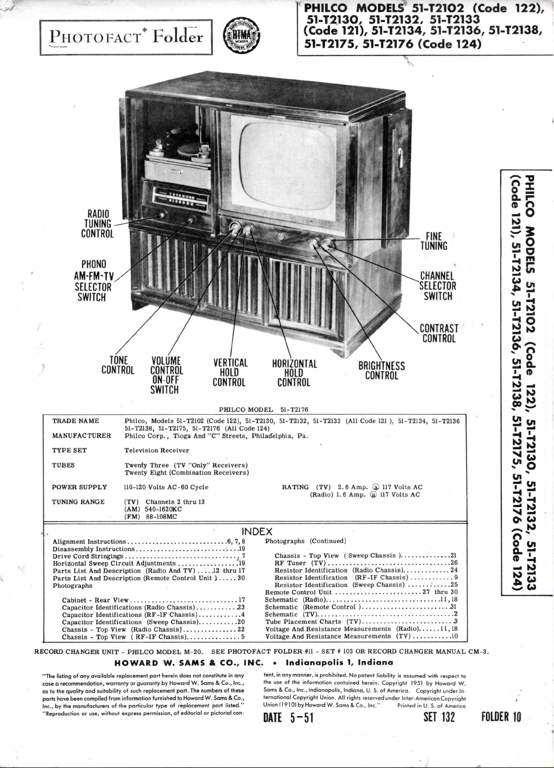
PHOTO
RADIO
TUNING
CONTROL
PHONO
AM-FM-TV
SELECTOR
SWITCH
FACT*
Fold
er
PHILCO
MODELS
51-T213O,
(Code
121),
51-T2175,
51-T21O2
51-T2132,
51-T2134,
51-T2176
51-T2133
51-T2136,
(Code
FINE
TUNING
CHANNEL
SELECTOR
SWITCH
(Code
124)
122),
51-T2138,
O.
r-
(D ft
_
O
»o
SB
TONE
CONTROL
TRADE
NAME
MANUFACTURER
TYPE
SET
TUBES
POWER
SUPPLY 110-120
TUNING
RANGE
Alignment
Disassembly
Drive Cord
Horizontal Sweep Circuit Adjustments
Parts
Parts
Photographs
RECORD
"The listing
case a recommendation, warranty
as
to the
parts have been
Inc.,
by the
"Reproduction
Instructions
Instructions
Stringings
List
And
List
And
Cabinet - Rear
Capacitor Identifications (Radio
Capacitor
Identifications
Capacitor Identifications (Sweep Chassis)
Chassis
- Top
Chassis
- Top
CHANGER
of any
available
quality
and
suitability
compiled
manufacturers
or
use, without express permission,
Philco, Models 51-T2102 (Code 122),
51-T2138,
Philco
Television Receiver
Twenty
Twenty
(TV)
(AM)
(FM)
6, 7, 8
f
Description (Radio
Description (Remote Control
View
17
View (Radio
View ( RF-IF
UNIT - PHILCO
HOWARD
replacement part
or
of
such
from information furnished
of the
particular
VOLUME
CONTROL
ONOFF
SWITCH
51-T2175, 51-T2176 (All Code 124)
Corp.,
Tioga
Three
(TV
Eight (Combination Receivers)
Volts
AC-60
Channels 2 thru
540-1620KC
88-108MC
19
19
And TV)
Chassis)
(RF-IF
Chassis)
Chassis)
guaranty
replacement
22
Chassis)
MODEL
M-20.
W.
SAMS & CO., INC. • Indianapolis
herein
does
by
Howard
part.
to
Howard
type
of
replacement
of
editorial
VERTICAL
HOLD
CONTROL
PHILCO
And
"C"
Streets,
"Only"
Receivers)
Cycle
13
J2
thru
PHOTOFACT
in any
of
these
Sams & Co.,
part
listed."
pictorial
17
Inc.,
con-
Unit ) 30
23
4
20
5
SEE
not
constitute
W.
Sams & Co.,
The
numbers
W.
or
7
HORIZONTAL
HOLD
CONTROL
MODEL
51-T2176
51-T2130,
INDEX
51-T2132, 51-T2133 (All Code
Philadelphia,
tent,
the
Sams & Co., Inc., Indianapolis,
ternational
Union
DATE
Pa.
RATING
(TV)
(Radio)
Photographs
Remote Control
Schematic (Radio)
Schematic (Remote Control ) 31
Schematic (TV)
Tube
Voltage
Voltage
FOLDER
use of the
(Continued)
Chassis
- Top
RF
Tuner (TV)
Resistor
Resistor
Resistor
Placement Charts (TV)
And
And
in any
(1910)
View ( Sweep
26
Identification (Radio
Identification (RF-IF Chassis)
Identification
Unit
11,18
2
Resistance
Resistance Measurements (TV)
#11
- SET t 103 OR
manner,
is
prohibited.
information contained herein. Copyright 1951
Copyright
Union.
by
Howard
W.Sams & Co., Inc." Printed
5-51
BRIGHTNESS
CONTROL
121 ),
51-T2134, 51-T2136
2.6
Amp.
® 117
1.6
Amp. ® 117
(Sweep
27
3
Measurements (Radio)
1,
Indiana
No
patent
Indiana,
All
rights
reserved
Volts
Volts
Chassis
) 21
Chassis)
24
Chassis)
RECORD
liability
U. S. of
9
;
CHANGER
is
assumed
America. Copyright under
under
Inter-American
CONTRAST
CONTROL
AC
AC
25
thru
30
11,18
10
MANUAL
with
respect
by
Howard
Copyright
in
U. S. of
America
SET
132
CM-3.
to
W.
In-
FOLDER
o
*?
28.
10
CO
S|
Ui
S?
K>
Os
ft"
0
in
f
5
—
K>
10
_
K)
10
-H
to
Page 2
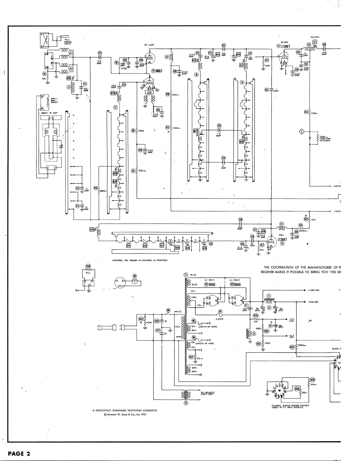
A
PHOTOFAa
STANDARD
©Howard
W.
Sami & Co.,
NOTATION
Inc.
SCHEMATIC
1951
THE
COOPERATION
RECEIVER
MAKES
IT
POSSIBLE
OF THE
MANUFACTURED
TO
BRING
YOU T HIS SEF
OF
Th
PAGE
2
Page 3
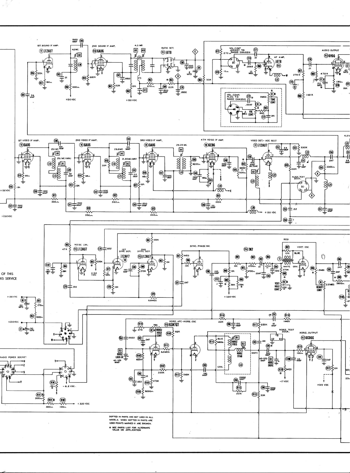
DOTTED
IN
BWTS
WHEN
ARE NOT
DOTTED
MODELS.
USED POINTS MARKED X ARE
USED
IN ALL
JN
PARTS
ARE
Page 4
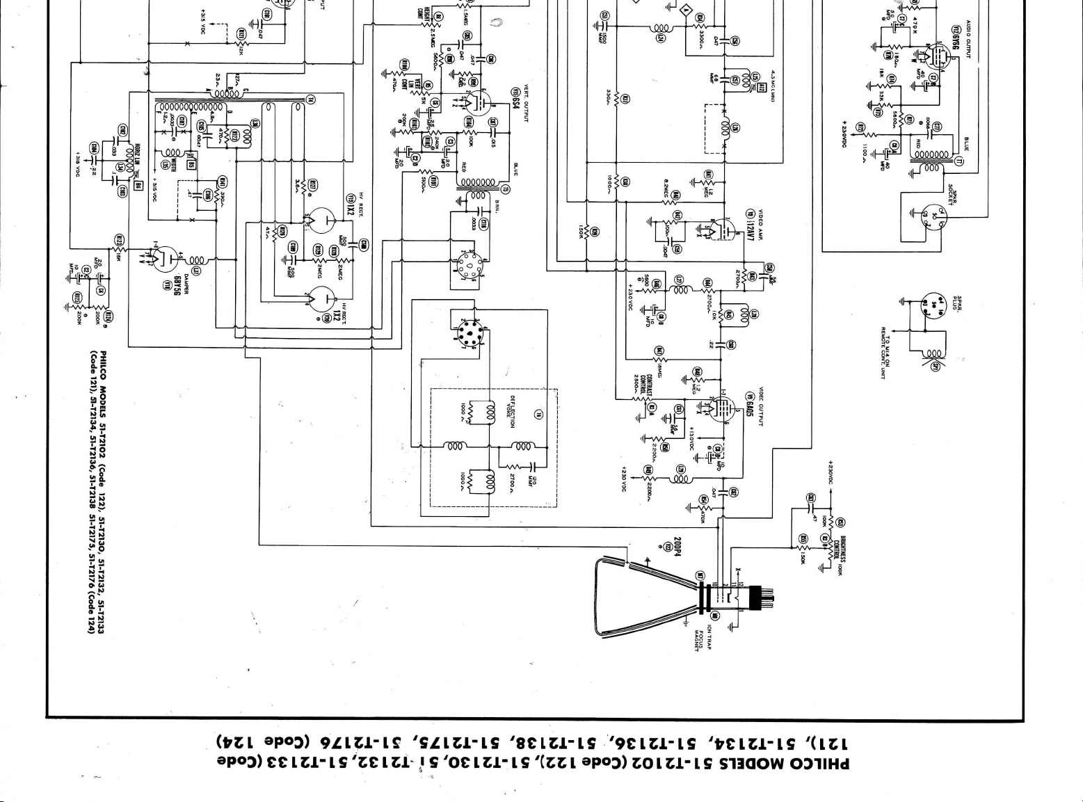
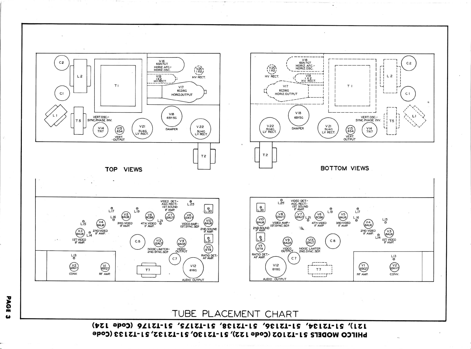
PHILCO MODELS
121),
51-72134, 51-72136, 51-72138, 51-72175, 51-72176
51
-72102
(Code
122),
51
-721
3O, 5 I 721
32,
51
-721
(Code
33
(Code
124)
II
(00*
Page 5
/'
*
RECT.
VI7
/
1
V
(
/'V2d|
\i
\
HV
/'
[]
6CD6G
\1
/
V22 \ 5U4G
\V
RECT
VI6 i
63N7GT
i
HORIZ.AFCHORIZ.OSC.
VI9
1x2
s
HV
RECT-
~~ — -]
]
L
1
1
i
i
1
!
~
-;j
/
;:(
PUT
__.—
^\
/
y
J
DAMPER
5U4G
S
/
\.
i
1
j
| | | '
I
^
T
1
I
1 1
,
>>
\
/
V2I \ —
VLVRKT./
V^
^X
1
SYNC PHASE
'
N^\
\ \
fV{5\
^
VERT
OUTPUT
VI4 }
I
V
— 1 I
' / \
i
L2
j
1 ^ ^x"x
1
'
i
j
r~i / \s
INV.
T5
\-'
/
L J
| 1 x
V
^
L1
7N?
/
f
-
^(^}
\-J(i9
\-
H
\
CC
ILL- L S
'ZCI
TUBE
ti~
1S
PLACEMENT
'OC1
ZL~
IS
'(ZCI
["]
CHART
®P<>D)
CO
IZJL- L S
POTTOM
S11QOW
WIFW<J
ODIIHd
Page 6
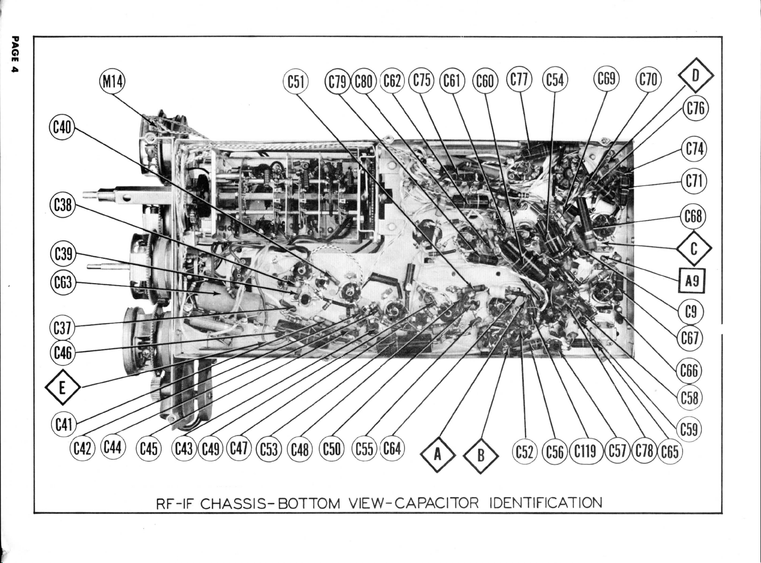
o
5
RF-IF
CHASSIS-BOTTOM
VIEW-CAPACITOR
IDENTIFICATION
Page 7
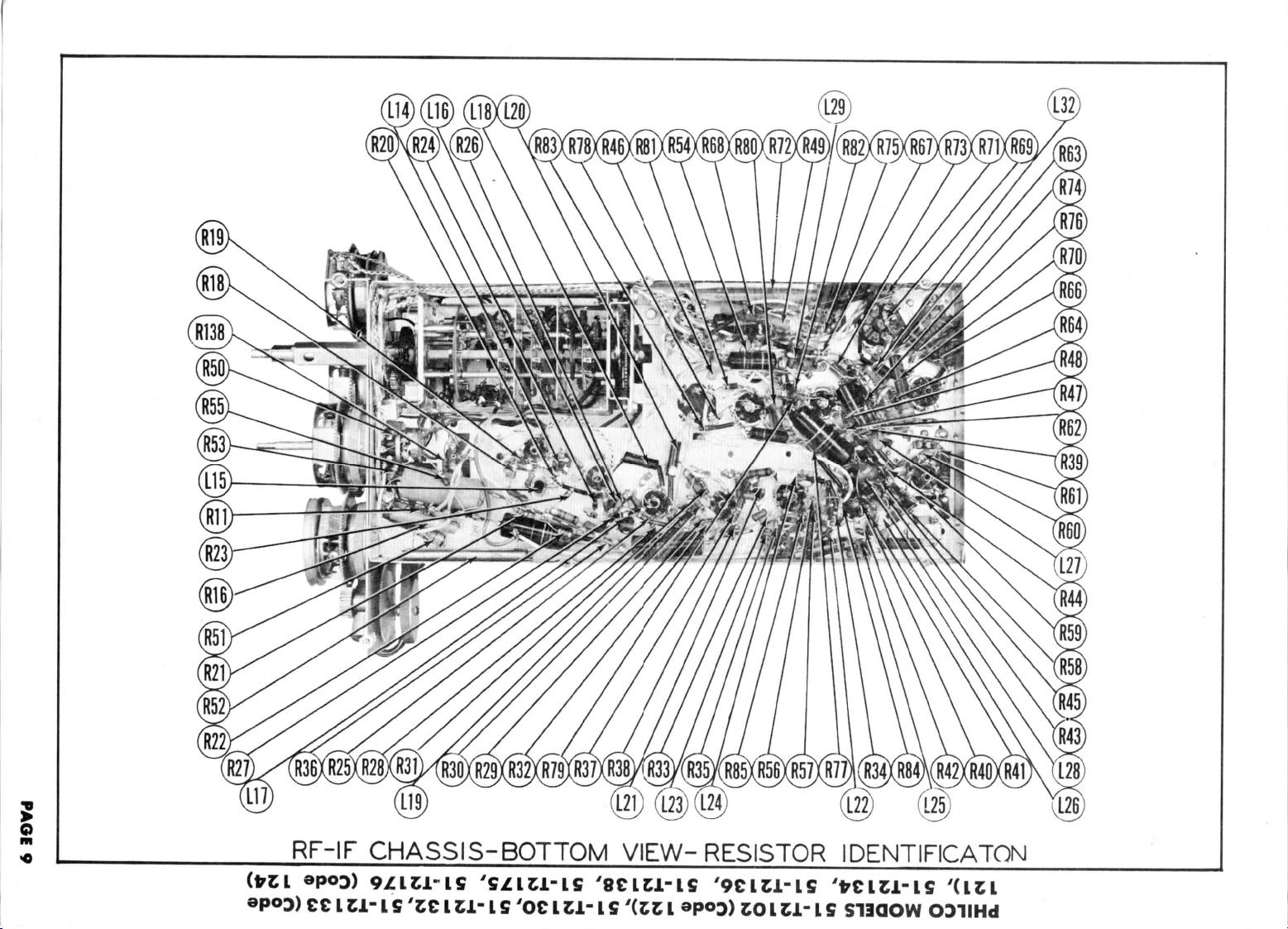
RF-IF
I
£1- L S
CHASSIS-BOTTOM
'
L S 'OC I Cl-
VIEW-RESISTOR
1
fi
'(t Z L
to I Cl- 1 S
IDENTIFICATON
S13QOW
ODIIHd
Page 8
o
m
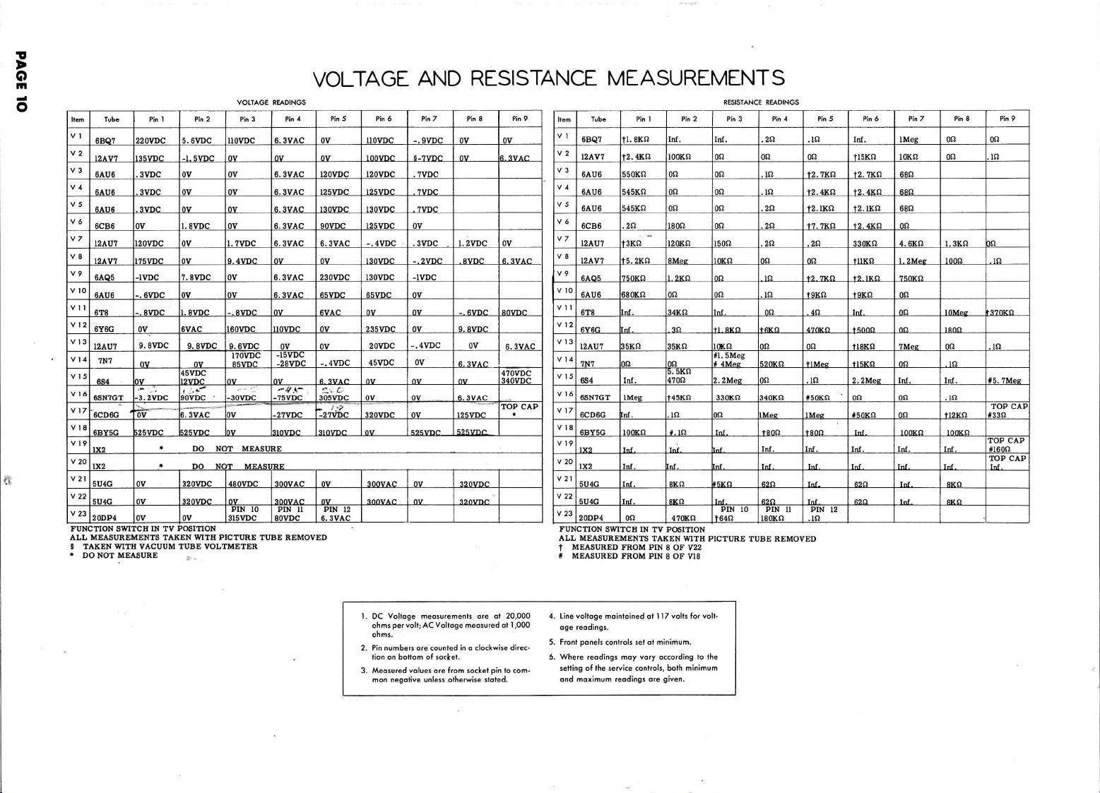
VOLTAGE
O
Hem
Tube
V
1
6BQ7
V
2
12AV7
V
3
6AU6
V
4
6AU6
V
5
6AU6
V6
6CB6
V7
12AU7
V
8
12AV7
V9
6AQ5
V
10
6AU6
Vll
6T8
V12
6Y6G
V
13
12AU7
V
14
7N7
V
15
6S4
V
16
6SN7GT
V17
6CD6G
V18
6BY5G
V
1 9
1X2
V20
1X2
V21
5U4G
V22
5U4G
V23
20DP4
FUNCTION SWITCH
ALL
MEASUREMENTS TAKEN WITH
§
TAKEN
* DO NOT
220VDC
135VDC
.3VDC
.3VDC
.3VDC
0V
120VDC
175VDC
-1VDC
-.6VDC
-.8VDC
0V
-3.2VDC
"
"6"v"
525VDC
ov
ov
ov
WITH
VACUUM
MEASURE
Pin
1
0V
9.8VDC
0V
* DO NOT
* DO NOT
IN TV
Pin
5. 6 VDC
-1.
5VDC
OV
OV
OV
1.8VDC
OV
OV
7.8VDC
OV
1.8VDC
6VAC
9.
8VDC
OV
45VDC
12VDC
i . *-"^
90VDC
6.3VAC
525VDC
320VDC
320VDC
OV
POSITION
TUBE
VOLTMETER
2
OV
OV
PICTURE
Pin
3
UOVDC
OV
OV
OV
OV
OV
1.
7VDC
9.4VDC
OV
OV
-.8VDC
160VDC
9.
6VDC
170VDC
85VDC
OV
-30VDC
MEASURE
MEASURE
480VDC
OV
PIN 10
315VDC
TUBE
READINGS
VOLTAGE
Pin
4
6.
3VAC
OV
6.
3VAC
6.3VAC
6.
3VAC
6.3VAC
6. 3 VAC
OV
6.
3VAC
6.
3VAC
OV
110VDC
OV
-15VDC
-28VDC
OV
-*>.-
-75VDC
-27VDC
310VDC
300VAC
300VAC
PIN
11
80VDC
REMOVED
Pin
OV
ov
120VDC
125VDC
130VDC
90VDC
6.3VAC
OV
230VDC
65VDC
6VAC
OV
OV
-.4VDC
6.3VAC
'I.
C
305
VDC
_ ; •?
-27VDC
310VDC
OV
OV
PIN 12
6.
3VAC
AND
5
Pin
6
110
VDC
-.9VDC
100VDC
120VDC
125VDC
130VDC
125VDC
-.4
130VDC
130VDC
65VDC
OV
235VDC
20
45VDC
OV
OV
320VDC
OV
300VAC
300VAC
VDC
VDC
5-7VDC
.7VDC
.7VDC
.7VDC
OV
.3VDC
-.2
-1VDC
OV
OV
OV
-.4
OV
ov
ov
ov
525VDC
OV
OV
RESISTANCE
Pin
7
Pin
8
VDC
VDC
OV
OV
1.2VDC
.8VDC
-.6VDC
9.8VDC
6.
OV
6.3VAC
125VDC
525vnn
320VDC
32ovnc
OV
3VAC
OV
fi.3VAC
OV
6.3VAC
80VDC
470VDC
340VDC
TOP CAP
6.
Pin
9
3VAC
*
MEASUREMENTS
Tube
Item
V
1
6BQ7
V
2
12AV7
V
3
6AU6
V
4
6AU6
V
5
6AU6
V
6
6CB6
V
7
12AU7
V
8
12AV7
V9
6AQ5
V
10
6AU6
V 1 1
6T8
V
12
6Y6G
V
13
12AU7
V
14
7N7
V
15
6S4
V
16
6SN7GT
V
17
6CD6G
V
18
6BY5G
V
19
1X2
V20
1X2
V21
5U4G
V22
5U4G
V23
20DP4
FUNCTION SWITCH
ALL
MEASUREMENTS TAKEN WITH
f
MEASURED
#
MEASURED
•fi.BKn
T2.4KS1
550KS3
545KSJ
545KI2
.2n
t3Kfi
t5.2Kn
750KS!
680KS2
Inf.
Inf.
35Kn
on
M.
IMeg
nf.
lOOKn
Inf.
Inf.
Inf.
Inf.
on
FROM
FROM
Pin
1
Inf.
lOOKf!
on
on
on
ison
120Kn
SMeg
1.2KSJ
on
34Kn
.sn
35Kfi
on
5.
470n
t45Kn
.in
Tnf.
8Kn
IN TV
POSITION
PIN 8 OF V22
PIN 8 OF
Pin
5Kn
#.m
nf.
sxn
470Kn
V18
2
RESISTANCE
Pin
Inf.
on
on
on
on
on
i5on
lOKn
on
on
Inf.
ti.RKn
lOKn
#1.
5Meg
*
4Mee
2.2Meg
330Kn
on
Inf.
nf.
»5Kn
Inf.
PIN 10
t64n
PICTURE
3
un
tsKn
on
340KS2
IMee
TUBE
READINGS
Pin
4
.2n
on
.in
.in
.2(1
.2(1
.2(1
on
.in
on
on
520Kn
tson
Inf.
Inf.
62n
62n
PIN 11
IBOKn
REMOVED
Pin
.in
on
T2.7Kn
t2.4Kn
t2.1Kn
t7.mn
.2n
on
f2.7Kn
t9Kn
.4n
470Kn
on
tlMee
.in
*50Kn
IMee
tson
Inf.
Inf.
Inf.
Inf.
PIN 12
.in
5
Pin
6
Pin
7
Pin
8
Pin
9
Inf.
TlBKn
t2.mn
t2.4Kn
t2.iKn
t2.
4Kn
330Kn
tiiKn
t2.mn
t9Kn
Inf.
tsoon
tisKn
ti5Kn
2.2Meg
on
*50Kn
Inf.
Inf.
Inf.
62n
Ban
IMeg
lOKn
68n
ean
68n
on
4.6Kn
1.2Mep
7ROKn
on
on
on
7Meg
on
Inf.
on
OS!
looxn
Inf.
Inf.
Inf.
Tnf.
on
on
i.sKn
loon
lOMef
ifinn
on
.in
Inf.
.in
ji2Kn
looKn
Inf.
Inf.
BKn
RKn
on
.in
jn
.in
f370Kn
.in
*5.7Meg
TOP CAP
#33n
TOP CAP
#ieon
TOP CAP
Inf.
1.
DC
Voltage
ohms
ohrr
2.
Pin
numbers
tion
3.
Measured
mon
per
volt;
on
bottom
negative
measurements
AC
Voltage
are
counted
of
socket.
values
are
unless
measured
in a
from
socket
otherwise
are at
clockwise
pin to
stated.
20,000
at
1,000
direc-
com-
4.
Line
age
5.
Front
6.
Where readings
setting
and
voltage maintained
readings
panels
controls
may
of the
service
maximum readings
controls, both minimum
at
117
volfs
set at
minimum.
vary according
are
given.
for
volt-
to the
Page 9
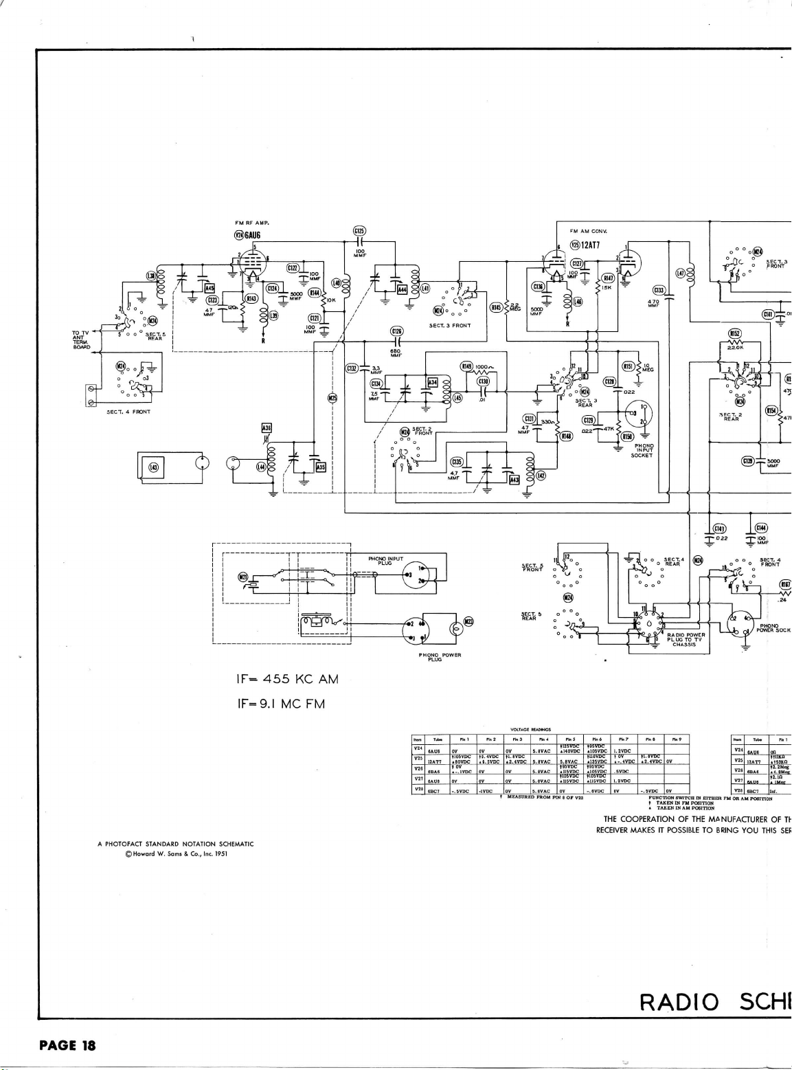
FM
RF
AMP.
PAGE
18
A
PHOTOFACT
STANDARD
©Howord
NOTATION
W.
Sams & Co., Inc.
1F=
IF=9.I
SCHEMATIC
1951
455 KC AM
MC
FM
Tub*
n.1
ov
j'a$c.
ov
-.svoc
PI.!
OV
;vi™.
ov
-1VDC
Item
V24
6AU
V25
12A
7
V26
BBA
V27
6AU
V28
6BC
Pi 3
„
"**™i
OV
ov
JURED
rhj
.SVAC
BVAC
.8VAC
.BVAC
.8VAC
FROM
Pin S
195VDC"~
U15VDC
OV
PIN 8 OF V2Z
pma
-$Hr-
TuSTOC
-.6VDC
RECEIVER
B.7
1.2VDC
•-•*vgg_
1.2VDC
OV
THE
COOPERATION
MAKES
n.8
Pin?
•Z-^VPC
-.5VDC
OV
FUNCTION
SWITCH
IN
IN FM
IN AM
OF THE
POSSIBLE
EITHER
POSITION
POSITION
MANUFACTURER
TO
t
TAKEN
«
TAKEN
IT
RADIO
H«,
Tubv
V2^
V25
BBAB
m
SAUfi
V28
8BCT
FM OR AM
POSITION
BRING
YOU
THIS
SCHl
OF
on
HllKO
taan
Int.
Phi
SER
Th
Page 10

ufct
mi
Phi
J-in3
IBL__
on
.1S3KD
IZ__
fa.zMeg
t!
i
IMfig
7
U.
1RER
OF
THIS
U
THIS SERVICE
on
ilSKfi
00
on
•ITXO
on
^^
OR
00
Ph4
.en
.Rn
.31)
.31!
CHEMATIC
FUNCTION
IN TV
SWITCH
PinS
tB.3KH
.615
_t_9Kn
on
SWITCH SHOWN
POSITION
SEQUENCE
Pin*
nas.fi
tllKfl
tinui
Rn^
pin
a
'
izon
PinP
Inf.
n
132-10
PAGE
11
Page 11

PAGE
12
Cl
C2A
C3
C4
C5
C6
C7A
C8A
C9
CIO
Cll
C12
C13
C14
CIS
CIS
C17
C18
C19
C20
C21
C22
C23
C24
C25
C26
C27
C28
C29
C30
C31
C32
C33
C34
C35
C36
C37
C38
C39
C40
C41
C42
C43
C44
C45
C46
C47
C48
C49
C50
C51
C52
CSS
C54
CSS
C56
VI
V2
V3
V4
V5
V6
V7
V8
V9
V10
Vll
V12
VI
3
V14
V15
vie
V17
vie
VI
9
V20A
V21
V22
V23A
ITEM
No.
B
C
D
B
C
B
C
D
ITEM
No.
RF
Converter
1st
2nd
3rd
4th
AGO
Video
1st
Video
1st
Video
2nd
Ratio
AF
Audio
2nd
Noise
Vert.
Sync.
Vert.
Horiz.
Oscillator
Horiz. Output
Damper
H.
H.V.
B
H.
L.V.
L.V.
Picture
B
Picture
CAP.
40
50
30
10
20
20
20
50
25
30
40
50
40
10
20
10
2
30
20
5
10
220
3.3
220
.5-3
220
220
220
220
.56
1.5
5
33
.5-3
.5-3
10
220
220
1
1500
15
220
220
470
1500
1500
39
100
1500
1500
22
33
1500
.22
1500
1500
1500
470
1500
56
.22
.1
8
.047
Amplifier
Video
Video
Video
Video
Rectlfier-
Detector
Sound
Amplifier
Sync.
Sepe
Output
Sound
Detector
Amplifier
Output
Sync. Sep.
Limiter
Oscillator
Phase
Output
AFC -
V.
Rectifie
Rectifie
V.
Rectifie
Rectifie
Rectifie
Tube
Tube
RATING
VOLT
475
475
475
475
300
300
300
25
25
450
350
25
450
450
450
450
50
30VAC
S>
601.
200
200
200
200
USE
IF
IF
IF
IF
IF
IF
Amp.
Amp.
Amp.
Amp.
Amp.
Amp.
Inv.
TV
PARTS LIST
REPLACEMENT
PHILCO
PART
No.
6BQ7
12AV7
6AU6
6AU6
6AU6
6CB6
12AU7
12AV7
6AQ5
6AU6
-
6T8
6Y6G
12AU7
-
7N7
6S4
Horiz.
6SN7GT
6CD6G
6BY5G
1X2
1X2
1B3GT
5U4G
5U4G
20DP4
20DP4A
Capacity
values
and
Paper
Capacitors,
PHILCO
PART
No.
30-2568-48
30-2584-3
30-2417-18
30-2417-18
30-2417-8
30-2417-9
30-2570-73
30-2570-41
30-2417-7
30-2355-3
62-020309011
30-1221-13
62-010409001
30-1225-11
30-1221-9
30-1225-11
31-6520-1
30-1225-11
30-1225-11
30-1225-11
30-1225-11
30-1221-16
30-1221-8
30-1221-13
62-0330090011
31-6520-1
31-6520-1
30-1224-48
30-1225-11
30-1225-11
30-1224-71
30-1225-19
62-015409011
30-1225-11
30-1225-11
62-147001001
62-215001011
62-215001011
62-039409011
62-110009001
62-215001011
62-215001011
62-022009001
62-03300001
62-215001011
45-3505-49
62-215001011
62-215001011
62-215001011
62-147001001
62-215001011
62-056409001
45-3505-49
45-3505-47
30-1224-13
45-3505-62
AF1062X4G
PRS350/24
AFH6J10I8A
SI1.5NPO
SI33
SI10N750
SI220
SI220
TUBES
given
AEROVOX
PART
No.
E4A100
PRS25/50
AF8422J
E26E6
E62A2
SI20
SI15NPO
sno
SI220
SI3.3NPO
SI220
SI220
SI220
SI220
SI220
SI5NPO
SI1500
SI15
SI220
SI220
SI470
SI1500
SI1500
SIS
9
SHOO
snsoo
SI1500
SI22
SI33
SI1500
P488-22
SI1500
SI1500
SI1500
SI470
SI1500
SI56
P488-22
P288-1
SI8.2NPO
P288-047
AND
(SYLVANIA
DATA
STANDARD
REPLACEMENT
6BQ7
12AV7
6AU6
6AU6
6AU6
6CB6
12AU7
12AV7
6AQ5
6AU6
6T8
6Y6G
12AU7
7N7
6S4
6SN7GT
6CD6G
6BY5G
1X2
1X2
1B3GT
5U4G
5U4G
20DP4
20DP4A
CAPACITORS
in the
rating
PART
mmfd.
No.
column
DATA
UPT53150-
UPT345-
UPT42145
BB2-50T
GT2P25
PTE4S5
and in
REPLACEMENT
CENTRALAB
D6-200
TCZ-4.7
D6-100
D6-221
TCZ-3.3
D6-221
829-3
D6-221
D6-221
D6-22I
D6-221
TCZ-1.5
TCZ-4.7
D6-330
829-3
829-3
TCN-10
D6-221
D6-221
TCZ-1
D6-152
D6-150
D6-22I
D6-221
D6-471
D6-152
D6-152
D6-390
D6-101
D6-152
D6-152
D6-220
D6-330
D6-152
D6-152
D6-152
D6-152
D6-471
D6-I52
D6-560
DF-104
D6-100
DF-503
DESCRIPTIONS
or
Equivalent)
RMA
BASE
TYPE
9AJ
9A
7BK
7BK
7BK
6CK
9A
9A
7BZ
7BK
9E
7AC
9A
SAC
9AC
8BD
5BT
6CN
7CB
7CB
3C
5T
5T
12D
12D
a
re
in
mfd.
for
for
Mica
CORNELL-
DUBILIER
PART
No.
UPT4045
230
BR2035A
BR502A
435C5
1W5D15
1W5D15
5W5Q4
5W5T1
1W5D15
1W5D15
5W5Q4
1W5D15
GT2P25
1W5D15
1W5D15
1W5D15
5W5T5
1W5D15
5W5Q5
PTE4P1
5W5Q1
and
PART
GP1K-20
NPOK-5
GP1K-10
GP2K-220
NPOK-3.3
GP2K-220
GP2K-220
GP2K-220
GP2K-220
GP2K-220
NPOK-1.
NPOK-5
GP1K-33
N750K-10
GP2K-220
GP2K-220
GP2L-0015
GP1K-15
GP2K-220
GP2K-220
GP2K-470
GP2L-0015
GP2L-0015
GP1K-39
GP1K-100
GP2L-0015
GP2L-0015
GP1K-22
GP1K-33
GP2L-0015
GP2L-0015
GP2L-0015
GP2L-0015
GP2K-470
GP2L-0015
GP1K-56
NPOK-8.2
Ceramic
ERIE
No.
5
Electrolytic
Capacitors.
SPRAGUE
PART
TVL-1820
TVA-1608
TVA-1206
TVL-3723
TVL-4840
TVA-1301
19C19
19C13
19C13
19C13
19C13
19C13
19C13
19C24
19C4
19C13
19C13
29C8
19C22
19C13
19C13
19C15
29C8
29C8
MS-44
19C11
29C8
29C8
19C23
19C24
29C8
2TM-P22
29C8
29C8
29C8
19C15
29C8
19C28
2TM-P22
2TM-P1
19C3
2TM-S47
NOTES
No.
IDENTIFICATION
AND
INSTALLATION
Filter
-
Filter
•
Filter
A
Decoupling
Vert.
Output Dec.
Vert.
Output Dec.
Decoupling
Bias
Filter
*
Vert.
Output Cathode
Filter
Output
Screen
utput
Cathode
Output
Decoupling
Decoupling
Decoupling
Decoupling
t
Stabilizing
Cap
Motor
Capacitor
Fixed
Trimmer
Fixed
Padder
Fixed
Padder
RF
Coupling
Neutralizing
AGC
Filter
Variable
Trimmer
RF
Amp. Grid
RF
Amp. Grid
RF
Amp.
Plate
RF
Coupling
RF
Coupling
RF
Coupling
RF
Coupling
RF
Coupling
Variable
Trimmer
Variable
Trimmer
Osc.
Grid
Cap
Osc. Feedback
Osc.
Plate
Dec.
Osc. Coupling
Conv.
Plate
Trimmer
Filament
Coupling
Filter
Trimmer
Coupling
Filter
V.
IF
Trimmer
Coupling
Filter
Filter
V. IF
V. IF
V. IF
Coupling
Bypass
Reel.
Filter
Bypass
Diode
Filter
Dec.
Bypass
Dec.
Dec.
Dec.
Screen
Cathode
Plate
Fixed
Conv.
Filament
IF
AGC
1st V. IF
Fixed
IF
AGC
2nd
Fixed
IF
AGC
AGC
3rd
4th
4th
IF
RF
AGC
AGC
RF
V.
Video Coupling
CODES
NOTES
t
Dec.
Page 12

TV
ITEM
No.
C57
C5B
C59
C60
C61
C62
C63
C64
C65
C66
C67
C68
C69
C70
C71
C72
C73
C74
C75
C76
C77
C78
C79
C80
C81
C82
C83
C84
C85
C86
C87
C88
C89
C90
C91
C92
C93
C94
C95
C96
C97
C98
C99
C100
C101
C102
C103
C104
C105
C106
C107
C108
C109
C110
cm
CU2
C113
C114
C115
cue
C117
CU8
C119
Some models
Some
Some
Some models
Some
Not
Some models
Some models
ITEM
No.
R1A
B
C
R2A
B
R3A
B
R4A
B
R5
.
33-5563-36
&
Fashion shaft
Note
A
ITEM
No.
R6
H7
R8
R9
RIO
Rll
R12
PARTS
RATING
VOLT
CAP.
68
56
.0047
600
.22
400
56
.047
400
400
.47
56
400
.01
1500
.0033
400
330
1500
.0022
400
400
.01
.0047
600
200
.
015
400
.0068
.
l
400
400
. 01
1000
.
0068
400
.022
200
.
015
500
180
400
.
047
400
. 01
600
.
0047
200
.
022
400
.047
400
.
047
400
.
015
500
120
400
.
0022
200
.15
200
*.
022
400
.047
1000
180
500
10000
600
.001
500
150
500
10
500
1200
500
390
1000
33
400
.047
400
.033
.1
400
400
.22
600
.
0047
200
.47
600
.
003
10000
500
20000
500
600
.01
600
.01
.1
400
.1
200
.1
200
.1
200
.1
200
.1
200
400
.
0033
33
u:
models
models
u:
models
used
in all
u
ui
RATING
RESIST-
WATTS
ANCE
2
Meg
5 Meg
Shaft
End
75KJJ
250KS2
2500SJ
100KJ1
2.5Meg
Shaft
5000SJ
1.
Additional
When
RATING
RESISTANCE
10KJ2
3300
20%
470KS2
20%
470KS2
20%
3300
20%
1000S2
20%
100KJ2
is
replacing,
LIST
PHILCO
PART
No.
62-068409011
62-056409001
45-3505-56
45-3505-48
62-056409001
45-3505-62
45-3500-4
62-056409001
45-3505-58
62-215001011
45-3505-55
60-10335407
62-215001011
45-3505-54
45-3505-58
45-3505-56
45-3505-59
45-3505-52
45-3505-64
45-3505-57
45-3505-60
45-3505-59
30-1224-5
45-3505-62
45-3505-58
45-3505-56
45-3505-60
45-3505-62
45-3505-62
45-3605-59
60-10125237
45-3505-54
45-3505-48
45-3505-43
45-3505-62
30-1244-5
60-30103404
45-3505-52
60-10155407
30-1244
60-20125404
30-1244-6
45-3505-62
45-3505-61
45-3505-64
45-3505-49
45-3505-56
45-3505-34
30-1229-5
30-1229-6
30-1226-1
30-1226-1
45-3505-47
30-4634
30-4634
30-4634
30-4634
30-4634
e
10MFD
in
ise
section
in
ui
u:
C8D
:se
this
section
,se .
001MFD
se .
022MFD
models.
se
220MMF
ise . 01MFD
I
^
¥
2
|
2
mglr.
to
in
PHILCO
PART
.33-5563-37
33-5563-35
33-5563-33
33-5565-10
Not
req.
33-5546-10
part number
duplicate original.
use
parts
to be
WATTS
i
66-3108340
66-1338340
I
A
66-4478340
66-4478340
I
66-1338340
I
i
66-4108340
2
AND
AEROVOX
PART
SI68
SI56
P688-0047
P488-22
SI56
P488-047
484-5
SI56
P488-01
SI1500
P688-0033
SI330
SI1500
P688-0022
P488-01
P688-0047
P288-015
P488-0068
P488-1
P488-01
P1068-0068
P488-022
P2S8-015
1469-0002
P488-047
P488-01
P688-0047
P488-022
P488-047
P488-047
P488-015
1469-00015
P688-0022
P288-15
P488-022
P488-047
1469-HV-0002
1467-01
P688-001
1468-00015
1468-00001
1468-0004
P488-047
P488-033
P488-1
P488-22
P688-0047
P288-47
P688-0033
HV10C
HV20C
P688-01
P688-01
P488-1
P288-
P288-
P288-
P288-
P288-
P688-0033
SI33
this application.
in
this
applicatio.
in the
application
in
this application.
in
this
application,
in
this
application.
this
application.
REPLACEMENT
No.
PART
IConcentrikit
JB18-139X
JB12-114
(E-187
Qll-239
RQ
W-5000
for
original
parts
used with
"Concentrikit".
REPLACEMENT
PHILCO
PART
No.
1
DESCRIPTIONS
CAPACITORS
REPLACEMENT
ENTRALAB
No.
PART
D6-680
D6-560
D6-472
D6-560
DF-503
06-560
6-103
6-152
06-332
06-331
6-152
6-222
6-103
D6-472
D6-682
DF-104
D6-103
DF-203
D6-181
DF-503
D6-103
D6-472
DF-203
DF-503
D6-121
D6-222
DF-203
DF-503
D6-102
D6-152
D6-100
D6-391
DF-503
D6-472
D6-332
TV3-501
TV3-502
D6-103
D6-103
DF-104
DF-104
DF-104
DF-104
DF-104
DF-104
D6-332
D6-330
m
and
of
C7C.
Mfgrs.
CONTROLS
DATA
IRC
No.
A
A
RTV-263
A
RTV-262
RTV-261
AM-84-S
FKS-1/4
i
43-5000
models
51T2134,
including
DATA
IRC
PART
No.
BTS-10K
BTS-330
BTS-330
BTA-IOOO
CCONTO
DATA
CORNELL-
DUBILIER
No.
PART
W5Q7
W5Q5
PTE6D5
GT4P25
W5Q5
PTE4S5
GT4P5
W5Q5
PTE4S1
W5D15
PTE6D3
W5T3
W5D15
PTE6D2
PTE4S1
PTE6D5
PTE6S15
PTE6D6
PTE4P1
PTE4S1
PTE16D7
PTE4S2
PTE6S15
5R5T2
PTE4S5
PTE4S1
PTE6D5
PTE4S2
PTE4S5
PTE4S5
PTE6S15
5R5T15
PTE6D2
PTE4S2
PTE4S5
1D3S1
PTE6D1
5W5T15
5W5T1
5W5T4
PTE4S5
PTE6S3
PTE4P1
GP4P25
PTE6D5
GT2P5
PTE6D3
PTE6S1
PTE6S1
PTE4P1
PTE4P1
PTE4P1
PTE4P1
PTE4P1
PTE4P1
PTE6D3
5W5Q3
section
C7C is not
part # 60-10225417.
CLAROSTAT
PART
No.
AN-83
AK-1
VK-135
i
51T2136
nut
bushing
.
RESISTORS
ALL
RESISTORS
Antenna
AGC
Network
RF
Amp. Grid
RF
Amp. Grid
RF
Amp.
RF
Amp.
Mixer Grid
No.
PART
GP1K-68
GP1K-56
GP2M-0047
GP1K-56
GP1K-56
821-01
GP2L-0015
GP2M-0033
GP2K-330
GP2L-0015
GP2M-0022
821-01
GP2M-0047
821-01
821-01
GP2K-180
821-01
GP2M-0047
GP2K-120
GP2M-0022
GP2L-001
GP2K-150
GP1K-10
GP2K-390
GP2M-0047
GP2M-0033
821-01
821-01
GP2M-0033
GP1K-33
used,
CENTRALAB
PART
No.
and
51T2175.
Matching
Plate
Decoupling
Plate
Decoupling
(Continued)
ERIE
SPRAGUE
No.
PART
19C10
19C28
6TM-D47
4TM-P22
19C28
4TM-S47
4TM-5
19C28
4TM-S1
29C8
6TM-D33
9C14
29C8
6TM-D22
4TM-S1
6TM-D47
6TM-S15
6TM-D68
4TM-P1
4TM-S1
MB-D68
4TM-S22
6TM-S15
MS-32
4TM-S47
4TM-S1
6TM-D47
4TM-S22
4TM-S47
4TM-S47
6TM-S15
MS-315
6TM-D22
2TM-P15
4TM-S22
4TM-S47
1FM-11
6TM-D1
1FM-315
1FM-41
1FM-34
4TM-S47
6TM-S3
4TM-P1
4TM-P22
6TM-D47
2TM-P47
6TM-D33
6TM-S1
6TM-S1
4TM-P1
2TM-P1
2TM-P1
2TM-P1
2TM-P1
2TM-P1
6TM-D33
19C24
INSTALLATION
Volume
Tone Control - Rear
Attach
Per
Horizontal Hold Control - Front
Vertical
Contrast
See
Note
Brightness
Height
Control
Attach
to R4A Per
Vertical
IDENTIFICATION
- 10%
UNLESS OTHERWISE SPECIFIED
- See
IDENTIFICATION
No.
Fixed
Peaking
Video Amp. Cathode
Video Coupling
V.
Video Coupling
Pic.
S. IF
1st
S.
2nd
RF
RF
De-emphasis
Tone
Audio
Tone Comp.
Audio
AF
Audio
Output
Sync.
Sync. Coupling
Sync.
Sync. Coupling
Vert. Sync. Coupling
Integrator Network
Integrator
Vertical
Vert. Sweep Coupling
Vertical Shaping
Horiz.
Horiz.
AFC
AFC
Horiz.
Horiz.
Fixed
Horiz, Sweep Coupling
Voltage Divider
Horiz.
Horiz.
Damper
Damper
Damper
RF
Damping
Damping
Damping
Damping
Damping
RF
NOTES
Control - Tapped
Instructions
Hold
Control - Rear
Control - Wire
1.
Control - Rear
Instructions
Linearity
CODES
Note
2
CODES
AND
INSTALLATION
Output Cathode
Tube
S. IF
IF
S. IF
Bypass
Bypass
Comp.
Amp. Dec.
Horiz,
Horiz. Sweep Coupling
Horiz. Feedback
Fixed Trimmer
Horiz.
Fixed Trimmer
Voltage Doubler
H.
V.
Line
Line
Bypass
Fixed
Bypass
Control
NOTES
Trimmer
Cathode
Coupling
Dec.
Coupling
Dec.
Coupling
* *
Coupling
§
Coupling
Plate
»
Coupling
Coupling
Network
Discharge
Sync. Coupling
Sync..
Coupling
Filter
Filter
AFC
Plate
Osc. Grid
Trimmer
Feedback
Discharge
Output
Screen
Filter
Filter
Filter
Sweep
Coupling
#
Filter
Filter
Filter
Trimmer
#
(&
IMeg - Front
in
"Concentrikit"
Wound - Front
Cap
10
5
^" ft
2°
h
°
-*
m
W
IT
w
U
2
W
00
"
0
N
Oi
Oi
-i
Ol
K>
.
•
w
-• ft
-
PAGE
13
"
&
&
°-
£
9
Page 13

R13
R14
R15
R16
R17
R18
R19
H20
R21
H22
R23
R24
R25
R26
R27
R28
R29
R30
R31
R32
R33
R34
H35
R36
H37
R38
R39
R40
R41
R42
R43
R44
R45
R46
R47
R48
R49
R50
R51
R52
R53
R54
R55
R56
R57
R58
R59
R60
R61
R62
R63
R64
R65
R66
R67
R68
R69
R70
R71
R72
R73
R74
R75
H76
R77
R78
R79
R80
RSI
R82
R83
R84
R85
R86
R87
R88
R89
R90
R91
R92
R93
R94
R95
R96
R97
R98
R99
R100
R101
R102
R103
R104
R105
R106
R107
R108
Rill
R112
ITEM
R109
R110
RU3
R114
R115
R117
R118
R119
R120
No.
RESISTANCE
sson
20%
6800B
2200B
20%
12KB
lOKn
i5Kn
esn
sson
sson
330B
12KB
68B
330B
33KB
12KB
esn
330B
8200B
ison
5600B
330KB
3300B
lOOKn
lOOKn
330B
looon
150KB
8.2Meg
1.2Meg
loon
2700B
2700B
10KB
4700B
l.SMeg
1.2Meg
2200B
2200B
270B
1300B
100KB
470Kn
ISOKn
120KB
150B
looon
680Kn
i2Kn
22KB
270B
51KB
33KB
68KB
lOMeg
270KB
lOOKn
470Kn
ison
5600B
noon
33KB
18KB
270B
15B
1.2Meg
lOKn
6.
8Meg
270KB
100KB
i5Kn
220KB
5%
39Kn
47KB
10KB
IMeg
15KB
56KB
56KB
4700B
10KB
4700B
4700n
270Kn
1.
5Meg
15Kn
seoon
5%
2.2Meg
470B
5100B
240Kn
200KB
lOOKn
20%
820KB
470KB
330KB
8200B
82KB
47KB
3.3Meg
560KB
33KB
6800B
22KB
22KB
220KB
IMeg
20%
icon
20%
IMee
RATING
20%
20%
20%
20%
5%
5%
5%
5%
5%
WATTS
f
5
5
5
5
1
i
I
5
z
2
10
i
\
2
1
I
I
2
1
1
i
i
i
1
j
a
i
I
i
2
2
10
1
2
A
I
I
5
?
2
i
^
i
|
1
1
2
1
1
i
k
i
i
I
|
i
i
i
5
1
I
1
I
1
1
i-
1
1
i
1
i
REPLACEMENT
PHILCO
PART
66-1338340
66-2688340
66-2228340
66-3103340
66-3158340
66-0688340
66-1338340
66-1338340
66-1338340
66-3128340
66-0688340
66-1338340
66-3338340
66-3128340
66-0688340
66-1338340
66-2828340
66-1188340
66-4338340
66-2338340
66-4108340
66-4108340
66-1338340
66-2108340
66-4158340
66-5828340
66-5128340
66-1108340
66-2278340
66-2278340
66-3108340
66-2474340
66-5188340
66-5128340
33-1335-97
66-2228340
66-1275340
33-3435-31
66-4108340
66-4478340
66-4158340
66-4128340
66-1158340
66-2108340
66-4688340
66-3124340
66-3224340
66-1278340
66-3338340
66-3688340
66-6108340
66-4278340
66-4108340
66-4478340
66-1185340
66-2565340
33-3435-33
66-3334340
66-3185340
66-1278340
66-0158340
66-5128340
66-3108340
66-5688340
66-4278340
66-4108340
66-3158340
66-3398340
66-3478340
66-3108340
66-5108340
66-3155340
66-2478340
66-3108340
66-2478340
66-2478340
66-4278340
66-5158340
56-3158340
66-5228340
66-1478340
33-1335-18
66-4104340
66-4824240
66-4474340
66-4334240
66-2828340
66-3824340
66-3474340
66-5334240
66-4564240
66-3334340
66-2688340
66-3228340
66-3228340
66-4224340
33-1350
66-1104340
RESISTORS
No.
DATA
IRC
PART
No.
BTS-330
BTS-6800
BTS-2200
BTS-330
BTS-330
BTS-330
BTS-330
BTS-330
BTS-180
BTE-330K
BTS-3300
BTS-100K
BTS-100K
BTS-330
BTS-1000
BTS-150K
BTS-8.2Meg
BTS-1.
2Meg
BTS-100
BTS-2700
BTS-2700
BTS-10K
BTA-4700
BTS-1.
8Meg
BTS-1.
2Meg
1
3/4A-2250
BTS-2200
BW-2-270
1
3/4A-1250
BTS-100K
BTS-470K
BTS-I50K
BTS-120K
BTS-150
BTS-1000
BTS-680K
BTA-12K
BTA-22K
BTS-270
BTS-47K
BTS-33K
BTS-68K
BTS-lOMeg
BTS-270K
BTS-100K
BTS-470K
BW-2-180
BW-2-5600
1
3/4A-1100
BTA-33K
BTB-18K
BTS-270
BTS-1.
2Meg
BTS-10K
BTS-6.8Meg
BTS-270K
BTS-100K
BTS-15K
BTS-220K-5%
BTS-39K
BTS-47K
BTS-10K
BTS-lMeg
BTB-15K
BTA-56K
BTA-56K
BTS-4700
BTS-10K
BTS-4700
BTS-4700
BTS-270K
BTS-1.
SMeg
BTS-1
5K
BTS-5600-5%
BTS-2.2Meg
BTA-470
1
3/4A-5000
BTA-100K
BTS-820K-5%
BTS-470K
BTA-330K-5%
BTS-8200
BTA-82K
BTS-47K
BTA-3.3Meg-5%
BTA-560K-5%
BTA-33K
BTS-6800
BTS-22K
BTS-22K
BTS-220K
BTS-lMeg
CCONT.3
IDENTIFICATION
Mixer Decoupling
Antenna Coil Shunt
Osc.
Plate
Decoupling
Osc.
Plate
Decoupling
Osc. Grid
1st
Video
IF
1st
Video
IF
1st
Video
IF
AGC
Network
AGC
Network
2nd
Video
IF
2nd
Video
IF
decoupling
3rd
Video
IF
3rd
Video
IF
3rd
Video
IF
4th
Video
IF
4th
Video
IF
4th
Video
IF
4th
Video
IF
Video
Det. Diode Load
Video
Det..
Diode
AGC
Network
AGC
Network
solation
Voltage
Divider
Voltage
Divider
3ias
Network
Video Amp. Grid
Video Amp. Cathode
Video Amp.
Plate
Video Amp.
Video
Plate
Peaking
Decoupling
- See
EJias
Network
Video
Output
Video
Output
Contrast
Control
Decoupling - Wire
Decoupling - Wire
Voltage
Divider
Picture
Tube Grid
Picture
Tube Cathode
1st
Sound
IF
st
Sound
IF
st
Sound
IF
2nd
Sound
IF
2nd
Sound
IF
Voltage Divider
Balancing
De-emphasis
AVC
Network
Tone Compensation
AF
Amp. Grid
AF
Amp.
Plate
AF
Amp.
Plate
Output
Grid
Output
Cathode - Wire
Output
Screen - Wire
Output Decoupling - Wire Wound
Voltage Divider
Voltage Divider
feedback
Network
Feedback Network
st
Sync.
Sep.
3ias
Network
Voltage Divider
2nd
Sync. Sep. Grid
2nd
Sync. Sep.
Voltage Divider
Voltage Divider
*ioise
Limiter
Series
Test
Sync.
Sync.
Sync.
Jack
Phase
Phase
Phase
Sync.
Phase
Sync.
Phase
Voltage Divider
Integrator
Integrator
Integrator
Vert.
Osc. Grid
Vert.
Osc.
Plate
Vert.
Osc.
Transformer
Vert.
Peaking
Vert.
Output Grid
Vert.
Output Cathode
Vert.
Output
Voltage Divider
Voltage
Divider
Damping
Horizontal
AFC
Horizontal
AFC
Horizontal
AFC
Horizontal
AFC
Horizontal
AFC
Voltage
Divider
Voltage Divider
Horizontal Osc. Grid
Horizontal Osc.
Horizontal Osc.
Horizontal Osc. Coil
Horizontal
Feedback
Horizontal Feedback Network
Horizontal
Feedback
Parasitic
Suppressor
Horizontal Output Grid
- See
Amp.
Grid
Amp. Cathode
Amp. Decoupling
Amp. Grid
Amp. Cathode
Transformer
Amp. Grid
Amp. Cathode
Amp.
Screen
Transformer
Amp. Cathode
Amp.
Plate
- See
Load
Coil
Shunt
Note
16
Grid
Plate - Wire
Shunt
Wound
Wound
Amp. Grid
Amp. Cathode
Amp.
Decoupling
Amp. Grid
Amp. Decoupling
- See
Note
6
Decoupling
Wound
Wound
Grid
Plate
- See
Note
Load
Inv. Grid
Inv. Grid
Inv.
Plate
Inv. Decoupling
Inv. Decoupling
- See
Note
- See
Note
Shunt
- See
Note
Plate
Decoupling - Wire Wound
- See
Note
- See
Note
Grid
Grid
Cathode
Filter
Plate
Plate
Coil
Shunt
Shunt
Network
Network
- See
Shunt
Shunt
- See
Wound
7
- See
- See
8
9
10
11
11
Note
Note
Note
3
Note
Note
Note
12
CODES
4
5
TV
ITEM
No.
R121
R122
R123
R124
R125
R126
R127
R128
R129
R130
R131A
R132
R133
R134
R135
R136
R137
R138
R139
R140
R141
R142
Note
Note
Note
Note
Note
Note
Note
Note
Note
Note
Note
Note
Note
Note
Note
Note
RESISTANCE
12KS1
470S2
16KB
200KS2
200KS!
4.7SJ
3.
en
2Meg
2Meg
loon
soon
B
400SJ
150KS2
100KSJ
10KS!
6300S2
.240
22O
ion
.osn
.osn
390SJ
100KSJ
2.
Some
3.
Some
4.
Some
5.
Some
6.
Some
7.
Some
8.
Some
9.
Some
10.
Some
11.
Some
12.
Some
13.
Some
14.
Some
15.
Some
16.
Some
17. Not
20%
PARTS
RATING
20%
models
models
models
models
models
models
models
models
models
models
models
models
models
models
models
used
WATTS
in all
5
2
1
1
1
i
f
1
1
5
10
10
i
2
1
a
.1
20
2
1
i
1
1
use
use
use
use
use
use
use
use
use
33000
use
use
use 4.
use
use
use
5600Si
models.
LIST
PHILCO
PART
33-1335-103
66-1475340
66-3184340
66-9474360
33-1352
33-1352
33-1335-105
33-3445-4
66-4158340
66-4108340
66-3108340
33-3446-1
66-0228340
66-0104340
66-1391340
4700S1
15K.fi
resistor
150S2
resistor
6800fi
resistor
22Kfi
resistor
240Kfi
180KS1
680KSi
resistor
22QK.fl
470KO
70
resistor
piece
of
27Kn..2
resistor
AND DES
RESISTORS
REPLACEMENT
No.
I
3/4A-12K
BTB-470
BTA-18K
BW-j-4.7
BW-i-3.6
1
3/4A-500
BTS-150K
BTS-100K
BTS-10K
BW-2-.24
BW-1-22
BW-i-10
BW-1-390
wire
watt
BTA-100K
in
this
in
this
in
this
in
this
in
this
in
this
in
this
in
this
in
this application.
in
this
in
this
in
this
in
this
application.
resistor
in
this
resistor
resistor
resistor
resistor
resistor
resistor
DATA
IRC
PART
No.
application.
application.
application.
application.
application.
application.
application.
application.
application.
application.
application.
in
place
application.
C(
of
R8!
TRANSFORMS
Tl
ITEM
No.
PRI.
117VAC
®
2.6A
SEC.
1
660VCT
.33uADC
RATING
® 6A
®4.
SEC.
2
5VAC
SEC.
4
6.3VAC
4A
SEC.
.6.3VAC
®
5.4A
SEC.
5
6.3VAC
®
1.6A
PHILCO
3
PART
No.
32-8488
TRANSFORMEI
ITEM
No.
PRI.
T2
117VAC
® .. 53A
ITEM
No.
DC
PRI.
won
T3
ison
T4
Tap
640S3
T5
T6A
12S!
47n
T7
LI
L2
ITEM
No.
ITEM
SP1
SP2
ITEM
No.
B
No.
Drill
IMPEDANCE
PRI.
2.3KS2
FIELD
PM
.CONE
11
TOTAL
DIRECT
CURRENT
.ISA
.34A
15
15
SEC.
1
24VAC
®
1.85A
RATING
RESISTANCE
SEC.
365SJ
5.
in
23n
Tapl.2n
SEC.
on
SEC.
on
22SI
one new
mounting hole.
RATING
SEC.
3.sn
RATINGS
RES.
DIA.
1/2"
RATINGS
RESISTANCE
64n
49S>
RATING
2
3
DC
PRI.
2oon
V. C.
3.2n
V. C.
D.
C.
SEC.
2
SEC.
3
TRANSFORMER
PHILCO
PART
No.
32-8454
32-9644
TRANSFORMER
SEC.
.sn
1"
INDUCTANCE
(0
1. 5 Henries
2.5
PHILCO
PART
32-8367-5
PHILCO
PART
36-1611-7
CURRENT
1000
./•)
Henries
RES.
IMP.
DIA.
A-8112
DY-7
No.
REPLACEMENT
No.
PHILCO
32-8479-2
32-8478-2
PHILCO
PART
32-8493
REPLACEME
STANCOR
PART
No.
(J>
REPLACEMI
STANCOR
PART
A-3825
SPEAI
VIKING
PART
12J12
FILTER
PART
No.
No.
(S
No.
(D
Of
No.
C
1!
f
PAGE
14
Page 14

ENTIFICATION
I
iode
3upling
d
bode
ner
Shunt
d
hode
?en
ler
Shunt
iode
- See
Note
e
- See
Note
ode
mpling
oupling
ling
Wound
'ound
re
Wound
jpling
- See
jpling
- See
Note
8
Note
9
er
Shunt
itelO
oupling - Wire
tote 11
hunt
hunt
etwork
etwork
etwork
5
Note
Note
CODES
4
15
15
Wound
ITEM
T2
T3
T4
T5
T6A
ITEM
T7
SP2
ITEM
LI
L2
Tl
No.
SP1
ITEM
No.
R121
R122
R123
R124
R125
R126
R127
R128
R129
R130
R131A
R132
R133
R134
R135
R136
R137
R138
R139
R140
R141
R142
Note
Note
Note
Note
Note
Note
Note
Note
Note
Note
Note
Note
Note
Note
Note
Note
ITEM
No.
No.
ITEM
No.
B
CD
ITEM
No.
No.
TV
PARTS
RESISTANCE
i2Kn
470S!
18KS!
200Kn
200Kn
4.7n
3.
en
2Meg
2Meg
loon
soon
B
40on
150KS2
iooKn
lOKn
63oon
.24n
22n
ion
20%
.osn
.osn
39on
iooKn
Some models
2.
Some models
3.
Some
4.
Some models
5.
Some
6.
Some models
7.
Some models
8.
Some models
9.
Some models
10.
Some models
11.
Some models
12.
Some models
13.
Some
14.
Some
15.
Some models
16.
Not
17.
PRI.
11 7 VAC
®
2.6A
PRI.
11 7 VAC
® ..
53A
RATING
DC
RESISTANCE
PRI.
i9on
ison
Tap
23fl
640n
i2n
47n
Drill
one new
IMPEDANCE
PRI.
2.3Kn
FIELD
PM
•
CONE
11
1/2"
TOTAL
DIRECT
CURRENT
.ISA
.34A
RATING
20%
models
models
models
models
used
24VAC
®
RATING
SEC.
3.5n
RATINGS
RES.
DIA.
WATTS
5
2
1
1
1
1
1
1
5
10
10
?
2
20
2
1
±
1
1
use
use
use
use
use
use
use
use
use
use 4.
use
use
use
in all
RATING
SEC.
1
660VCT
.
33UADC
RATING
SEC.
1
1.85A
SEC.
365n
5.
in
Tapl.2n
SEC.
2
on
SEC.
3
on
22n
mounting
PRI.
2oon
V. C.
3.2n
V. C.
RATINGS
D. C.
RESISTANCE
64n
49n
LIST
PHILCO
PART
33-1335-103
66-1475340
66-3184340
66-9474360
i
33-1352
33-1352
33-1335-105
33-3445-4
66-4158340
i
66-4108340
66-3108340
z
33-3446-1
66-0228340
66-0104340
66-1391340
4700S2
resistor
ISKfl
resistor
use
ISOtJ
resistor
6800O
resistor
use
22KO
resistor
240Kft
resistor
180Kfi
resistor
680Kfi
resistor
33000
resistor
220K.fi
resistor
470KSi
resistor
7fi
resistor
piece
of
27Kn..2
5600O
resistor
models.
SEC.
2
5VAC
® 6A
SEC.
4
6.3VAC
®4.
4A
SEC. 2SEC.
TRANSFORMER
PHILCO
PART
32-8454
32-9644
hole.
TRANSFORMER
DC
RES.
SEC.
.50
IMP.
DIA.
1"
INDUCTANCE
(0
CURRENT
1. 5 Henries
2. 5
AND
RESISTORS
REPLACEMENT
No.
wire
watt
®
No.
36-1611-7
1000
Henries
DATA
PART
1
3/4A-12K
BTB-470
BTA-18K
BW-5-4.7
BW-i-3.6
1
3/4A-500
BTS-150K
BTS-100K
BTE-10K
BW-2-.24
BW-1-22
BW-3-10
BW-1-390
BTA-100K
in
this application.
in
this
application.
in
this application.
in
this application.
in
this
application.
in
this
in
this
in
this application.
in
this
in
this
in
this application.
In
this application.
in
this application.
resistor
in
this application.
TRANSFORMER
SEC.
3
6.3VAC
5.4A
SEC.
5
6.3VAC
®
1.6A
TRANSFORMER
3
32-8493
A-8112
DY-7
PHILCO
PART
No.
32-8367-5
REPLACEMENT DATA
PHILCO
PART
No.
PHILCO
./>)
PART
32-8479-2
32-8478-2
DESCRIPTIONS
CCONT.J
IRC
No.
Horizontal
Output
Anti - Ringing Coil
Decoupling
Voltage Divider
Voltage
HV
Rectifier Filament - Wire
HV
Rectilier
HV
Filter
HV
Filter
Voltage Divider - Wire
Voltage
Voltage Divider - Wire
Voltage Divider
Bias
Bias
Decoupling - Wire
Filament Dropping - Wire
Isolation - Wire
Series
Filament Dropping - Piece
Filament Dropping - Piece
Centering
Isolation
application.
application.
application.
application.
in
place
of R89 and
PHILCO
PART
No.
32-8488
(POWER)
PHILCO
PART
No.
(SWEEP CIRCUITS)
REPLACEMENT
STANCOR
PART
No.
(D
REPLACEMENT
STANCOR
PART
A-3825
DATA
A-3000
A-3036
(AUDIO
No.
PART
P-3018
CD
SPEAKER
VIKING
PART
No.
12J12
FILTER
CHOKE
REPLACEMENT
STANCOR
PART
No.
- See
Divider
- See
Filament - Wire
Divider - Wire
Network
Network
Wound
Pilot
Light
Network - Wire
- See
Note
R90.
(POWER)
REPLACEMI
STANCOR
PART
No.
REPLACEMENT
STANCOR
PART
No.
MERIT
PART
No.
CD
OUTPUT)
DATA
MERIT
CHICAGO
No.
RO-2
OUAM
PART
No.
12A4A
DATA
PART
No.
(Continued)
IDENTIFICATION
Screen - Wire
Shunt
Wound
17
PART
CD
MERIT
Note
11
Note
Wound
Wound
Wound
Wound
Wound
NT
CHICAGO
PART
TS8-1
No.
No.
11
Wound
Wound
of
#24
of #24
DATA
PART
DATA
PART
No.
CD
CD
Drill
CHICAGO
PART
Wound
- See
Wire
Wire
MERIT
MERIT
No.
No.
CODES
Note
4
CHICAGO
PART
CHICAGO
PART
No.
No.
No.
NOTES
Vert. Block
Horizontal
Vertical
Horizontal Deflection Coil
Vertical Deflection Coil
INSTALLATION
one new
NOTES
Osc.
Output
Output
Trans.
NOTES
mounting
INSTALLATION
NOTES
Trans.
Trans.
hole.
ITEM
No.
L3
Ant.
L4
Ant.
L5
FM
L6
RF
L7
Ant.
L8
RF
L9
Mixer Grid
Coils
L10
Osc.
LH
RF
L12A
Fil.
B
Fil.
LI
3
1st
L14
2nd
L15
Adj.
Sound
L16
3rd
LI
7
21.
L18
Fil.
LI
9
4th
L20
RF
L21
5th
L22
Fil. Choke
L23
Peaking
L24
Peaking
L25
4.
Peaking
L26
Peaking
L27
Peaking
L28
Peaking
L29
Sound
L30
L31
Ratio
Trans.
L32
Fil. Choke
Horiz.
L33
Coil
L34
Horiz.
Width
L35
L36
Anti-Ringing
Coil
L37
Suppressor
Coil
ITEM
No.
Ml
ilo-Blo
M2
iee
M3
See
ITEM
No.
M4
ITEM
No.
M5A
RF
B
RF
Switch
M6
M7
MS
Ion
M9
Solenoid
M10
Solenoid
Mil
Solenoid Assembly
M12
Solenoid
M13
Motor
M14
Switch
Switch
M15
M16
Switch
Switch
Ml 7
Switch
M18
Switch
Ml 9
M20
Slip Ring
B3
Trimmer
B4
Trimmer
Safety
Safety
Safety
Mask
Mask
Mask
Knob
Knob
Knob
Knob
Knob
Knob
Knob
Knob
Knob
Knob
Knob
USE
Trans.
Trans.
Trap
Choke
Coils
Coils
Coils
Choke
Choke
Choke
Video
Video
Channel
Trap
Video
85MC
Choke
Video
Choke
Video
5MC
Del.
TYPE
SAG
Note
Note
BASE
Bayonet
PART
Tuner
Tuner
Focus
Trap
IF
IF
IF
Trap
IF
IF
Trap
IF
Osc.
Lin.
Coil
RATING
8/10Am[
TYPE
NAME
Magnet
Assembly
Assembly
Assembly
Assembly
Glass
Glass
Glass
PRI.
.8S!
.en
on
.4n
on
On
on
on
.152
.in
.in
.6J2
.2n
on
.2n
,10
.in
.2n
.in
.3n
.in
2.2n
3.
en
i.
eft
.4n
4.
4n
3.
sn
sn
.in
eon
ion
2.
sn
2n
DC RES
en
en
81!
46-2651
VOLTS
6-8
31-64'
31-64'
54-79
54-79
54-79
56-85
56-85
56-85
76-60
76-63:
76-63.
76-6K
76-60
54-47'
76-62
54-47'
76-60
54-47'
54-47!
FUSi
76-e
76-6
76-6
76-6
76-6
76-6
76-6
76-6
76-6
35-1
42-1
42-1
42-1
42-1
42-1'
42-1
42-1:
4
PH
P
Page 15

CRIPTIONS
ONT.3
•izontal
Output
i - Ringing
Coil
:oupling
tage
Divider
tage Divider
Itage
Itage
Itage
[tage
is
is
coupling - Wire
ament
lation - Wire
•ies
ament
ament
ntering
lation
/EEP
-3036
JDIO
PART
'-3018
ER
1OKE
iNCOR
iT
Rectifier
Filament - Wire
Rectifier
Filament - Wire
Filter
Filter
Divider - Wire
Divider - Wire
Divider - Wire
Divider
Network
Network
Dropping - Wire
Pilot
Light
Dropping - Piece
Dropping - Piece
Network - Wire
- See
ind
R90.
(POWER)
STANCOR
PART
(POWER)
STANCOR
PART
No.
CIRCUITS)
DATA
MERIT
PART
No.
-3000
CD
OUTPUT)
T
DATA
MERIT
No.
QUAM
PART
No.
12A4A
.ACEMENT
No.
- See
Note
REPLACEMENT
No.
REPLACEMENT
DATA
IDENTIFICATION
Screen - Wire
Shunt
- See
Note
Note
Wound
Wound
Wound
Wound
Wound
17
CHICAGO
PART
TSe-1
CHICAGO
PART
No.
RO-2
Q)
MERIT
PART
No.
(Continued)
CODES
Wound
11
11
Wound
Wound
Wound
- See
Note
4
of
#24
Wire
of #24
Wire
Wound
DATA
DATA
PART
No.
0)
CD
CHICAGO
PART
MERIT
PART
No.
MERIT
No.
INSTALLATION
Drill
No.
Vert.
Horizontal
Vertical
Horizontal
Vertical
one new
NOTES
CHICAGO
CHICAGO
PART
NOTES
Block Osc.
Output
Output
Deflection
Deflection
NOTES
mounting
INSTALLATION
NOTES
PART
Trans.
No.
No.
Trans.
Trans.
Coil
Coll
hole.
ITEM
No.
L3
Ant.
L4
Ant.
L5
FM
L6
RF
L7
Ant.
L8
RF
L9
Mixer
Coils
L10
Osc.
Lll
RF
L12A
Fil.
B
Fil.
L13
1st
L14
2nd
LI
5
Adj.
Sound
L16
3rd
LI
7
21.85MC
L18
Fil.
LI
9
4th
L20
RF
L21
5th
L22
Fil. Choke
L23
Peaking
L24
Peaking
L25
4.
5MC
Peaking
L26
Peaking
L27
L28
Peaking
Peaking
L29
Sound
L30
L31
Ratio Det.
Trans.
Fil. Choke
L32
Horiz. Osc.
L33
Coil
Horiz.
L34
Width
L35
Anti-Ringing
L36
Coil
Suppressor
L37
Coil
ITEM
No.
Ml
3AG
ilo-Blo
M2
See
M3
See
ITEM
No.
M4
Bayonet
ITEM
No.
M5A
RF
B
RF
M6
Switch
M7
Focus
M8
Ion
M9
Solenoid
M10
Solenoid Assembly
Mil
Solenoid
M12
Solenoid
Motor
M13
M14
Switch
Ml
5
Switch
Switch
M16
Switch
M17
Switch
M18
Switch
M19
M20
Slip Ring Assembly
B3
Trimmer
B4
Trimmer
Safety
Safety
Safety
Mask
Mask
Mask
Knob
Knob
Knob
Knob
Knob
Knob
Knob
Knob
Knob
Knob
Knob
USE
Trans.
Trans.
Trap
Choke
Coils
Coils
Grid
Coils
Choke
Choke
Choke
Video
Video
Channel
Trap
Video
Choke
Video
Choke
Video
Trap
IF
Lin.
Coil
TYPE
Note
Note
BASE
PART
Tuner
Tuner
Magnet
Trap
Glass
Glass
Glass
IF
IF
IF
Trap
IF
IF
RATING
8/10Am[
TYPE
NAME
Assembly
Assembly
Assembly
DC
PRI.
.8n
.852
On
.4n
OS!
OS!
on
Oft
.IS!
.in
.in
.SSI
.an
on
.2n
.in
.in
.2n
.in
.3n
.in
2.
2O
3.
en
1.8D
.4n
4.
en
4n
3.
en
5f!
en
.in
eon
ion
2.
en
sn
2n
45-2658-21
VOLTS
RES.
SEC.
.en
.an
.2n
.80
4sn
PHILCO
PART
FUSE
6-8
PHILCO
PART
76-6481-1
76-6440-1
76-6572
76-6126-4
76-6077-1
76-6416
76-6416
76-6416
76-6416
35-1465
42-1953
42-1950
42-1950
42-1950-1
42-1950
42-1950-1
42-1952
31-6473-22
31-6473-22
54-7943-28
54-7943-25
54-7943-27
56-8578-2
56-8578
56-8578-1
76-6064
76-6386
76-6387
76-6104-1
76-6048
54-4799
76-6213
54-4799
76-6048
54-4799
54-4750
COILS
REPLACEMENT
PHILCO
PART
No.
76-6459
76-6459
32-4438-2
32-4112-22
76-6463
76-6469
76-6468
76-5768
32-4112-22
32-4503
32-4359-10
32-4486
32-4303-3
32-4486
32-4496
32-4112-15
32-4486-6
32-4112-15
32-4486
32-4112-15
32-4143-16
32-4480-3
32-4463-5
32-4480-9
32-4480-8
32-4480-3
32-4449A
32-4450-2
32-4506
32-4501-1
32-4505
32-4480
32-4112-24
No.
HOLDER
27-4519-2
REPLACEMENT
19-1920
19-1921
19-1921
19-1920
DATA
313.800
DIAL
BEAD
AMPS.
COLOR
.15
Brown
MISCELLANEOUS
No.
Models 51-T2138, 51-T2176
Models 51-T2134, 51-T2136, 51-T2175
Models
51-T2138.51-T2176,
Models 51-T2134, 51-T2136, 51-T2175)
Channel
Selector
Fine Tuning (Models
Contrast
(Models 51-T2138, 51-T2176)
Volume
(Models 51-T2138, 51-T2176)
Remote
Control
Muting
(Models 51-T2138, 51-T2176)
Cycling
(Models 51-T2138,
Remote
Control Channel
Remote Control Fine Tuning (Models 51-T2138, 51-T2176)
Remote Control
Remote Control Volume (Models
Models
51-T2138,
Horizontal Lock
Horizontal
Models
51-T2175,
Models 51-T2136, 51-T2138
Model 51-T2134
Model 51-T2134
Models
5I-T2136,
Models 51-T2175, 51-T2176
Channel
Selector
Channel
Selector
Fine
Tuning (Models
Fine
Tuning (Models 51-T2134, 51-T2136,
Contrast
Volume
Tone
Brightness
Horizontal Hold
Vertical
Hold
Antenna
Tuning
(RF-IF)
DATA
MEISSNER
PART
No.
Includes
L4
Includes
L3
Switch
Wafer
Switch Wafer
Switch
Switch
Part
40
100
180
125
100
Tap
150
10.
With
With
Wafer
With
Wafer
With
of
L12A
Microhenries
Microhenries
Microhenries
Microhenries
Microhenries
at 4n
Microhenries
Microhenries
FUSES
LITTELFUSE
PART
No.
FUSE
HOLDER
357001
Length
Length
LIGHTS
REPLACEMENT
PHILCO
PART
34-2068
(Models
Contrast
(45-370MMF,)
Drive
DATA
No.
NOTES
(Switch
(Models 51-T2138, 51-T2176)
51-T2138,
51-T2138,
51-T2176)
Selector
(Models
51-T2176
(45-370MMF)
51-T2176
51-T2138
(Models 51-T2134, 51-T2136, 51-T2175)
(Models 51-T2138,
51-T2138,
Type
Part
of
51-T2176)
51-T2176)
(Models 51-T2138, 51-T2176)
51-T2138,
51-T2138,
51-T2176)
51-T2176)
Coils
Coils
Coils
Coils
of
#26
of #26
#47
Volume
51-T2176)
51-T2176)
51-T2175)
NOTES
Copper
Copper
Control
REMARKS
Wire
Wire
NOTES
on
—
TI
K>
I
u.0
Vo
K>
O
-*
m
0
*~
£
<"
>
Ul
01 7*
w
23
N
Ui
Ul
-i
Ui
K»
§.<•>
g-
o
-•
n
.
(D
PAGE
15
Page 16

V24
V25
V26
V27
V28
C120
C121
C122
C123
C124
C125
C126
C127
C128
C129
C130
C131
C132
C133
C134
C135
C136
C137
C138
C139
C140
C141
C142
C143
C144
0145
C146
C147
CHS
C149
C150
C151
C152
C153
C154
C155
RMS
R144
RMS
R146
R147
R148
RMS
R150
H151
R152
R153
R154
R155
R156
R157
R158
R159
R160
R161
R162
R163
R164
R165
R166
R167
L52
ITEM
ITEM
ITEM
L38
L39
L40
L41
L42
L43
L44
L45
L46
L47
L48
L49
L50
L51
ITEM
No.
No.
No.
No.
FM
RF
Amplifier
Converter
Phono
Pre-Amp.
1st IF
Amplifier
2nd
IF
Amplifier
Ratio
Detector
AM
Detector
RATING
CAP.
2
100
100
47
5000
100
680
100
.022
.022
.01
47
3.3
470
7.5
4.7
5000
5000
100
5000
100
.01
.01
.022
100
.01
.01
.0022
100
100
.0022
.01
100
220
.0022
220
RESISTANCE
12
on
lOKfi
2.2Meg
4700n
15Kfi
sson
icoon
47IO!
lOMeg
220KSJ
4700n
47Kf!
IMeg
47n
lOKn
2700S2
IMeg
12 Of!
2200n
47KS1
47KS2
47KS2
470Kn
3.3Meg
.24!!
USE
FM
Ant. Coil
Fil. Choke
RF
Choke
FM
RF
FM
Osc.
Loop Ant.
AM
Ant.
AM
Osc.
Fil. Choke
RF
Choke
1st AM IF
1st FM IF
2nd
FM IF
Ratio
Det.
Trans.
2nd
AM IF
RADIO
USE
-
-
VOLT
50
200
200
400
400
400
45-3505-41
400
45-3505-43
62-110009001
45-3505-41
400
400
45-3505-41
400
45-3505-43
62-110009001
62-110009001
400
45-3505-43
400
45-3505-41
62-110009001
62-122001001
400
45-3505-43
62-122001001
RATING
WATTS
Coil
Coil
Coil
Coil
PHILCO
PART
6AU6
12AT7
6BA6
6AU6
6BC7
Capacity
and
Paper
PHILCO
PART
No.
30-2417-7
62-110009001
62-110009001
62-051009001
30-1238-1
62-110009001
62-168001001
62-110009001
45-3505-43
45-3505-43
45-3505-41
62-051009001
30-1224-49
62-147001001
30-1224-65
30-1224-41
30-1238-1
30-1238-1
62-110009001
30-1238-1
62-110009001
45-3505-41
PHILCO
66-1128340
2
1
66-3108340
i
66-5228340
2
66-2478340
2
i
66-3158340
I
66-1338340
66-2108340
i
1
66-3478340
A
66-6108340
1
66-4228340
a
i
66-2478340
2
A
66-3478340
A
66-5108340
A
66-0478340
66-3108340
i
66-2278340
i
66-5108340
1
I
66-1128340
a
66-2228340
A
66-3478340
66-3478340
f
I
66-3478340
66-4478340
~z
66-5338340
i
2
66-8245340
DC
RES.
PRI.
OS!
.4!!
sn
OS!
on
2.2tl
ion
.4n
sn
12!J
i.sn
2.
in
4n
ien
PARTS
TUBES
REPLACEMENT
No.
values
given
Capacitors,
AEROVOX
PART
E26E6
SHOO
snoo
SI47
BPD-005
SHOO
SI680
SHOO
P488-022
P488-022
P48S-01
SI47
SI3.3NPO
SI470
SI4. 7NPO
BPD-005
BPD-005
snoo
BPD-005
snoo
P488-01
P488-01
P488-022
snoo
P488-01
P488-01
P6S8-0022
snoo
SHOO
P688-0022
P488-01
snoo
SI220
P688-0022
SI220
REPLACEMENT
PART
No.
SEC.
32-4467
32-4422-15
32-4422-10
32-4477
32-4414-2
32-4413-1
32-4458-1
32-4422-15
32-4422-10
i2n
32-4258-2A
32-4372A
i.
sn
2.
in
32-4372-2A
.sn
32-4310-3A
ien
32-4240-3A
LIST
(SYLVANIA
DATA
STANDARD
REPLACEMENT
6AU6
12AT7
6BA6
6AU6
6BC7
CAPACITORS
in the
and in
REPLACEMENT
CENTRALAB
No.
PART
D6-101
D6-101
D6-470
DD-502
D6-101
D6-681
D6-101
DF-203
DF-203
D6-103
D6-470
TCZ-3.3
D6-471
TCZ-4.7
DD-502
DD-502
D6-101
DD-502
D6-101
D6-103
D6-103
DF-203
D6-101
D6-103
D6-103
D6-222
D6-10I
D6-101
D6-222
D6-103
D6-101
D6-221
D6-222
D6-221
DATA
IRC
PART
No.
BTS-120
BTS-10K
BTS-4700
BTS-15K
BTS-330
BTS-1000
BTS-47K
BTS-lOMeg
BTS-220K
BTS-4700
BTS-lMeg
BTS-2700
BTS-120
BTS-2200
BTS-47K
BTS-47K
BTS-47K
BTS-470K
BTS-3.
3Meg
BW-2-.24
COILS
REPLACEMENT
PHILCO
PART
No.
AND
or
RMA
BASE
TYPE
7BK
9A
7BK
7BK
9R
rating
column
mmfd.
for
Mica
DATA
CORNELL-
DUBILIER
No.
PART
BB2-50T
5W5T1
5W5T1
5W5Q5
1D5D5
5W5T1
1W5T7
5W5T1
PTE4S2
PTE4S2
PTE4S1
5W5Q5
5W5TI
1D5D5
1D5D5
5W5T1
1D5D5
5W5T1
PTE4S1
PTE4S1
PTE4S2
5W5T1
PTE4S1
PTE4S1
PTE6D2
5W5T1
5W5T1
PTE6D2
PTE4S1
5W5T1
5W5T2
PTE6D2
5W5T2
RESISTORS
RF
Amp. Cathode
RF
Amp.
Converter Grid
Converter Decoupling
Osc. Grid
FM
Osc. Cathode
AM
Osc. Cathode
Tone Compensation
Phono Pre- Amp. Grid
Phono
Pre-Amp.
FM
Osc.
AM
Osc.
AVC
Network
1st IF
Amp. Cathode
1st IF
Amp.
1st IF
Amp.
2nd
IF
Amp. Grid
2nd
IF
Amp. Cathode
2nd
IF
Amp. Decoupling
Ratio Det. Diode Load
De-emphasis
Diode
Filter
Diode Load
AVC
Network
Filament Dropping - Wire
(RF-IF)
DATA
MEISSNER
PART
No.
DESCRIPTIONS
Equivalent)
NOTES
are in
mfd.
for
Ceramic
ERIE
No.
7
IDENTIFICATION
Decoupling
Wound
No.
1
3. 3
One
Tap
Tap
1
3. 3
Primary
Electrolytic
Capacitors.
SPRAGUE
PART
No.
TVA-1301
19C11
19C1I
19C25
29C1
19C11
19C17
19C11
4TM-S22
4TM-S22
4TM-S1
19C25
19C15
29C1
29C1
19C11
29C1
19C11
4TM-S1
4TM-S1
4TM-S22
19C11
4TM-S1
4TM-S1
6TM-D22
19C11
19C11
6TM-D22
4TM-S1
19C11
19C13
6TM-D22
19C13
CODES
Microhenry
Microhenries
Turn Around Cabinet
at . 5n
at
3.30
Microhenry
Microhenries
Tapped
No.
Screen
Plate
Plate
and
PART
GP1K-100
GP1K-100
GP1K-47
811-005
GP1K-100
GP2K-680
GP1K-100
821-01
GP1K-47
NPOK-3.3
GP2K-470
NPOK-4.
811-005
811-005
GP1K-100
811-005
GP1K-100
821-01
821
-01
GP1K-100
821-01
821-01
GP2M-0022
GP1K-100
GP1K-100
GP2M-0022
821-01
GP1K-100
GP2K-220
GP2M-0022
GP2K-220
Plate
Screen
Plate
PART
CL-1
CL-A
CL-1
CLA
IRC
IDENTIFICATION
AND
INSTALLATION
Stabilizing
Cap
FM
RF
Plate
FM
HF
Screen
FM
RF
Cathode
FM
RF
Fil.
RF
Coupling
RF
Coupling
Osc. Grid
Bypass
Audio
Coupling
Tone Comp.
AM
Mixer
Cathode
FM
Mixer
Cathode
Osc. Coupling
Osc.
Feedback
Fixed
Trimmer
Fixed
Trimmer
Conv.
Filament
AVC
Filter
Osc.
Plate
Dec.
Audio
Coupling
RF Bypass
Conv. Decoupling
AVC
Filter
RF
Bypass
RF
Bypass
1st
IF
Fil.
1st
IF
Plate
IF
Screen
IF
Grid
IF
Dec.
IF
Dec.
IF
Cathode
Bypass
Load
Filament
NOTES
4.2!!
at
5f!
Dec.
Cap
1st
2nd
2nd
2nd
2nd
RF
Diode
De-emphasis
Det.
and
CODES
NOTES
Dec.
PAGE
16
Page 17

RADIO
PARTS
LIST
AND
DESCRIPTIONS
(Continued)
ITEM
No.
M21
ITEM
No.
M22
M23
ITEM
M24
M25
No.
PHILCO
PART
76-4649
BASE
Bayonet
Bayonet
Switch
Tuning
Pointer
Scale
Panel
Knob
Knob
PART
No.
TYPE
NAME
Capacitor
PHONO
ASTATIC
PART
CARTIIDGE
VOLTS
6-8
6-8
PHILCO
PART
42-1938
31-2756-1
56-5630-28FCP
54-5106
54-8171
54-4798-4
54-4798
CARTRIDGE
REPLACEMENT
No.
NEEDLE
.25
.25
AMPS.
DATA
CARTRIDGE
BEAD
COLOR
Blue
Blue
PART
MISCELLANEOUS
No.
Function
36-492MMF,
Dial ( Models 51-T2175, 51-T2176)
Dial (Models 51-T2175, 51-T2176)
Diffusing
Function
Tuning
and
NEEDLE
SHURE
No.
DIAL
(Models 51-T2175, 51-T2176)
ELECTRO-VOICE
PART
C*»T»IDGE
No.
urrolr
NEE
DIE
LIGHTS
REPLACEMENT
PHILCO
PART
No.
34-2064
34-2064
NOTES
Phono-AM-FM-TV (Models 51-T2175, 51-T2176)
19-162MMF
(Models 51-T2175, 51-T2176)
Switch
(Models 51-T2175, 51-T2176)
DATA
(Models 51-T2175, 51-T2176)
REMARKS
Type
*44
(Radio
Type
*44
(Phono Compartment)
NOTES
Dial)
<"*
Ti
n
-2
o
±
a.
i-
18
10
23
REMOTE
FINE
TUNING
REMOTE
CONTRAST
REMOTE
VOLUME
ON-OFF
SW
(fiii)
REMOTE
CHANNEL
SELECTOR
HEIGHT
CONTROL
VERT
LIN
CONT
±n
10
_
to
co
00
*J
CO
Ul
Ui
r?
A
It
-•
K>
to
rf
lv
CO
£
CO
CABINET-REAR
VIEW
PAGE
17
Page 18

HORIZONTAL SWEEP
HORIZONTAL
Pre-set
Horizontal
Horizontal
Horizontal
Horizontal hold
Turn
Adjust
Connect
Adjust
necessary
triggering
not
control
Adjust
Bl
for
Turn
trol
slightly counter-clockwise.
Repeat
Turn
Turn
HORIZONTAL
Adjust
Adjust
Readjustment
the
adjustment
lock-in
stabilizing
drive
the set on and
the
horizontal frequency
the
vertical
the
horizontal
adjust
tendency
adjust
for
more
to
maximum clockwise.
Bl
until
sloping
bars.
the
hold
clockwise
and
the
check
the
hold
the
hold control clockwise
DRIVE,
the
horizontal
the
horizontal
OSCILLATOR
trimmer,
trimmer,
control
tune
input lead
stabilizing
Bl
to
keep
of the
than a slight
the
picture shows 4 bars
control
carefully note
and
adjustment
control
to
WDITH
drive
linearity
of B4 may be
ALIGNMENT
as
follows:
(B3),
one
turn counter-clockwise
core,
(B2),
until
the
screw extends
(B4),
one
turn counter-clockwise from maximum clockwise.
to the
center
of its
range.
in a TV
station,
preferably a test
slug,
(Bl),
to
synchronize
of an
oscilloscope
core
the
picture synchronized during adjustment
oscillator
may be
difference
to
maximum counter-clockwise
the
least
If
less
than
of B3
maximum counter-clockwise
and
check
AND
LINEARITY
trimmer
(B4) counter
slug
(B6) until
required
to
(B2) until
reduced
in
height,
sloping
number
2 1/2
bars
until
2 1/2 to 3 1/2
to see
the
obtain proper
to
the
by
downward
of
are
that
ADJUSTMENT
clockwise
picture
ADJUST
from
5/8
Inch
pattern.
the
picture
terminal
3 of the
broad
and
narrow
adjusting
for to do so
to the
and
interrupt
sloping
bars
present,
adjust
bars
and
adjust
the
picture
as far as
is
symmetrical from left
width
and
FOR
CIRCUIT
maximum
clockwise.
above
the
can.
horizontally.
horizontal
test
peaks
of the
waveform
of B2.
Note:
B2
until
the
rounded portion
will
render
the
oscillator
right.
Note:
If
this adjustment
the
signal
by
switching
just before
the
picture
B3
slightly
clockwise.
are
present
at the
pull-in
Bl
until 4 sloping
pulls into sync then falls
possible
best
linearity.
bars
without
to
EQUAL
socket.
In
moderately
of the
too
to
pulls into
point.
are
obtained.
out of
vertical
right.
PEAKS
ADJUSTMENTS
on the
scope
are of
strong
waveform
^sensitive..
is
made before
another channel
sync.
If
sync
at
maximum clockwise.
lines
appearing
equal height
signal
areas,
is
slightly lower than
Remove
the set has
and
more
in the
as
shown
free from
the
oscilloscope
thoroughly warmed
back again. Slowly turn
than
3 1/2
bars
picture.
noise,
the
are
in
figure
the
narrow
and
turn
present,
double
peak.
the
adjust
6. If
Do
the
hold
up,
adjust
hold con-
B3
0-
I-
18
K>
2
i,
m
JOE
22
DISASSEMBLY
TV
CHASSIS
REMOVAL
1.
Remove eight push-on
2.
Remove twelve wood
3.
Disconnect built-in antenna.
4.
Disconnect remote control motor plug.
5.
Disconnect picture tube
6.
Disconnect
7.
Disconnect yoke plug.
B.
Disconnect radio audio plugs.
9.
Disconnect power plug
10.
Disconnect radio power
11.
Disconnect
12.
Remove
four
13.
Remove eight
14.
Remove seven
15.
Remove seven
NOTE:
FOR
PICTURE TUBE
RADIO
CHASSIS
1.
Remove
two
2.
Remove
fourteen
3.
Disconnect
4.
Disconnect
5.
Disconnect phono power plug.
6.
Disconnect
7.
Remove four
type
control
screws
from
socket.
high
voltage
lead.
*•
to
RF-IF
chassis.
plug
.
speaker.
hex
nuts from
speaker.
hex
head
bolts
holding
hex
head
bolts
from
hex
head
bolts
from
REMOVAL
REMOVAL
push-on type control knobs.
wood
screws
securing
AM
antenna.
FM
antenna.
phono audio plug.
hex
head
bolts
from
knobs.
rear
mounting
RF-IF
sweep
IT IS
chassis.
FIG.
6
cover.
shelf
chassis.
chassis.
NECESSARY
rear
cover
Remove
INSTRUCTIONS
in
cabinet. Remove
Remove
Remove
chassis.
TO
REMOVE
to
cabinet.
chassis.
chassis.
Remove
THE
shelf
CHASSIS
rear
and
cover.
chassis.
AS
OUTLINED
ABOVE.
2.
10
2m
in
5?
H»
-
to
"
48
_
-I
r(
PAGE
19
Page 19

§
xT
C112
C3
SWEEP
C83
CHASSIS-CAPACITOR IDENTIFICATION
C82
Page 20

o
HI
K»
U
SWEEP
CHASSIS-RESISTOR
IDENTIFICATION
ap03)
CCI
Cl-1S
7CCI
Cl-1S
'OC L Cl-
IS
'(CC L «P<>3)
CO I Cl-1S
S13QOW
ODUHd
Page 21

i
RF
TUNER-RIGHT
SIDE
PAGE
26
RF
TUNER-LEFT
SIDE
Page 22

o
SWEEP
CHASSIS-TOP
VIEW
CC
9Z.IZ1.~IS
- L fi
'Zt
IZi'lS
'
'OC
'8CLC1-LS
~ I fi
'(CC 1 ap°3)
'
ZO
IZL'IS
S11QOW
ODllHd
Page 23

o
m
K)
Ki
—JM|
RADIO
CHASSIS-TOP
VIEW
Page 24

RADIO
CHASSIS-BOTTOM
VIEW-CAPACITOR
IDENTIFICATION
epo3)
cc
IZL- L S
'CCI
SI-1S
'OCI
Cl- L S
'(ZZI
ap<>3)
CO I ZL~ L fi
S13QOW
ODIiHd
Page 25

I
K)
RADIO
CHASSIS-BOTTOM
VIEW-RESISTOR
IDENTIFICATION
Page 26

SERVICE
INFORMATION
FOR
REMOTE
CONTROL
UNIT
RC-1
0
-f
o
±
0.
r-
18
to
u
»n
o
_
10
CJ
hJ
00
2
01
The
Remote Control
ver
from
operation
which
is
anism
.
any
of a
stored
point
group
on a
Unit
up to a
distance
of
switch
self-winding
makes
levers
it
of
reel,
possible
on a
thirty feet.
connects
to
tune
and
adjust
The
the
adjustments
control
control box. A flat
the
television
are
made
eight conductor
box to the
control
GENERAL INFORMATION
recei-
by the
cable,
mech-
The
Remote Control
Unit
consists
(A)
Control
(B)
(C)
Box and
Clutch
and
Motor Assembly
of
Reel Assembly
Gear
Assembly with
three
major
assemblies:
Solenoid
Coils
SB
K)
—
K>
KJ
—
01
PAGE
17
Page 27

There
The
inches
are
cable
past
three major
Thirty
Heel
Control
may be
stopped
the
desired
parts
feet
of
assembly
Box (2)
point
in the
Control
eight conductor
(3)
at any
distance
and
then letting
Box and
cable
up to
it
rewind
Reel Assembly:
(1)
thirty
feet
slowly
by
REEL
pulling
until
ASSEMBLY
it
about
the
pawl
six
on the
FIGURE
AND
CONTROL
reel
drops
by
pulling
cable.
Four
of
the
2.
BOX
in the
the
cable
(Double-Pole,
Control Box.
slot
locking
out
swiftly
Double-Throw)
the
about
reel
in
six
self-centering
place.
inches
The
cable
can be
and
then
letting
switches constitute
rewound
the
reel
on the
wind
the
reel
up the
contents
The
shaft
of the 24
or
counterclockwise direction
are
electrically
by
moving
one of the
positions.
As the
and
gear assembly (12),
The
drive
gear
trol shaft.
Through
into a rotary motion.
motor
shaft
Moving
one of the
also
energize
magnetic
force
(See
Fig.
3). The
PAGE
Volt
90°'
apart.
switch
motor
pinion
(5)
this
The
is
turning.
self-centering switches
an
associated
of the
solenoid
armature (22)
28
AC
motor (15) (See Fig.
by
applying
The
direction
levers
the
in
turn
turns
the
the
clutch
and
solenoid coil
and is
is
on the
drive belt (14) drives
clutch
secured
starts,
which
process
2)
Volts
which
the
gear
on the
The
to the
drive
will turn
AC to
either
the
motor
Box to
either
the
gear
assembly (13) rotating.
assembly (20)
and
gear-assemblies
will
revolve
Control
Box to
armature (22)
shaft
of the
24
in
Control
starts
and
three other clutch
gear
assemblies
(23).
pulled inward compressing
in
either a clockwise
of two
fields
rotates
is
determined
of the two
intermediate
on the
volume con-
as
long
start
the
is
then
attracted
the
return spring (27)
clutch
and
gear
FIGURE
GENERAL
which
off-center
pulley
are put
as the
motor will
assembly
OPERATION
by
3.
(20)
the
driver (8),
assembly
to
turned
overcome,
clicking
is
locking.
selector
the
by the
retaining
armature and,
make
to its
made
When
disengagement
as a
which
in
is
held
in
the
noise
to
An
control
the
position
driver turn
maximum rotation, clockwise
allowing
until
turn
in the
ordinary driver (9), instead
since
voltage
is
of the
washer
(30).
Therefore,
result, a tooth
turn,
rotates
the
by the
the
control
the
toggle(29)
the
voltage
is
control
from
clutch tooth
removed
opposite direction. This safety feature prevents
this
removed
the
clutch
of the
selected control.
toggle spring
in
normal operation; however,
or
to
slip
off the
from
of a
can be
rotated continuously.
the
solenoid (23),
with
the
and
clutch engages
The
(7)
which
counterclockwise,
clutch tooth
the
solenoid (23),
safety driver (8),
the
toggle(29).
gear
the
toggle (29)
toggle
maintains enough
the
with
is
return spring (27)
assembly
of the
safety
when
the
spring tension
an
accompanying
or
until
the
used
on the
moves
of the
driver
pressure
control
the
control
gears
channel
causes
with
safety
is
is
from
Page 28

X?
"°
o
E
O.
r-
(D ft
-
O
K>
ui
7*
Ml
°
a
a
to
_•
r!
>o
0,0
a
When
the
channel
noid
a
tuner
lever
the
sideways
upward
together
on
station
selector
pulls
the
tooth
the
to the
clutch
of the
clutch engages with
shaft (11) rotating.
is
subjected
detent plate assembly
to
close
motion.
The
parallel
control
box is
solenoid
through
selector
solenoid
switch
are
and
gear
The
to an
upward force
(32).
the
cycling switch
cycling switch (34)
the
station
selector
released
the
cycling
on the
energized.
assembly (21) inward,
roller
Until
before
Control
As the
the
toggle
(41A)
(See Fig.
as
well
the
centering lever (38)
(34),
the
is in
switch
the
cycle
switch
(34>
of the
as a
centering
series
in the
is
and the
Box (2) is
closing
ordinary
5)
fastened
lateral
pin
with
control
solenoid
operated,
the
driver
force
has
(46) will prevent
the
solenoid switch (10)
box.
voltage
magnetic force
completed,
OPERATION
the
motor
set up by the
solenoid switch
(9) and
starts
on the
centering
by the
star
wheel
traveled
far
If the
station
is
still
switch
(10).
When
sole-
(10),
enough
any
switch
applied
OF
and
the
of
and
CHANNEL
the
returns
spring (27)
the
of
control operation
operation, grounds
SELECTOR
the
cycle
is
completed,
detent plate (32)
the
centering
ing
the
switch. This cuts
to
ordinary
the
tuner
in
series
The
other section
shaft
(10),
push
driver
with
the
detent
star
the
(9),
no
voltage
the
of the
of the
the hot
lever
clutch
roller
wheel,
releasing
(38)
to the
off
voltage
to the
and
gear
and
opening
the
is
applied
cycling switch (34), remains
solenoid switch
channel
selector.
side
of the
(41B)
the
center
solenoid,
assembly
solenoid
to the
is
used
This switch,
speaker
rolls
tension
of the
out of
motor
voice
down
into
on the
detent
cycling
switch (34) thereby open-
and
motor, allowing
engagement
switch
(10).
During
or
solenoid
open.
to
mute
the
closed
coil.
one of the
detents
spring
(42)
the
with
the
toggle
manual rotation
as the
solenoid switch
sound during
only during remote
remote
PAGE
of
which
return
29
on
8.
0
-•
a
^
K>
Page 29

SERVICING
1.
2.
3.
4.
5.
6.
HINTS
Buzzing
a.
Armature
b.
Burrs
c.
Foreign
d.
Armature engaging solenoid switch (10) before
e.
Uneven
Armature Binds
a.
Foreign
Tuner
a.
Line voltage
b.
Faulty motor capacitor
c.
Faulty motor
d.
Faulty
e.
Tuner shaft (11) binding.
Clutch
a. Oil or
b.
Motor belt
c.
Driving pinion
d.
Burrs
e.
Leads
f.
Bent pinion
Clutch
a.
Clutch teeth more than 1/32" from toggle
Driver
a.
Driver
seating
on
pole-piece.
matter between armature
surface
on
Solenoid
matter
Fails
to
Rotate
too
(15).
transformer.(
and
has
.005 " to
and
Gear
Assemblies
grease
loose.
or
foreign
fouling
Teeth
Fails
gear
Fail
to
to
Rotate Control
loose
on
improperly
on
inside
Bushing
or
burrs
low.
(It
should
(4).
( The
.015 " end-play,
Fail
on
motor
belt
(5)
loose
on
matter
in
moving
parts.
shaft.
Engage Toggle
Shaft
control shaft.
of
armature
on
Solenoid
To
(14).
driving
gear
of
on
pole-piece
and
not be
shaft must
Rotate
gear
teeth.
Driver
When
Clutch
face
pole-piece.
(22).
Bushing
less
be
When
Motor
(13) shaft.
When
when
is
belt (14)
or
of
last
than
aligned
Is
Solenoid
clutch
Engaged
grease
solenoid.
1/64"
of
105
Volts)
so it
Energized.
is
Energized
is in
j
Do not
or the
belt
on
these
movement.
rotates
freely
neutral position.
allow
any oil or
driving
surface
parts
should
LUBRICATION
for a long period
parts
as
grease
of the
be
removed
Lubrication
follows:
is
applied
of
needing lubrication should
Use a
1.
2.
3.
4.
5.
Use
1.
2.
3.
4.
5.
6.
7.
Use a mixture
1.
Bearing surface
Use
1.
Reel
to
come
intermediate
with
time. However,
good
cup
Intermediate
All
Toggle (29)
Teeth
Reel
S.A.E.
Threads
Motor
Shaft
Fine
Studs
Bearings
Left
graphite
carbon
grease
pulley
gear
teeth.
of
of
clutch (20)
Bearings.
20 oil on the
and
bearing
Bearings
of
volume control pulley assembly
tuning
shaft.
of
link assembly
of
tuner drive shaft.
side
of
reel
of
on the
(left
side)
in
contact
with
pulley
tetrachloride.
at the
safety
(3) and
grease
of
following:
and
the
(12).
time
of
manufacture
in the
be
cleaned with carbon tetrachloride
on the
following:
and
gear
(12).
drivers
(8).
and
(21).
following:
surfaces
of the
(31).
washer.
and
graphite
reel
(3)
power
pawl.
drive
Any oil
event
on the
spring.
and
of
repairing
solenoid
(24).
following:
.
should
be
or
bushings.
sufficient
replacing
and
to
last
of
parts,
lubricated
PARTS
Part
Number
Cable
Control
Box
Assembly
Switch
42-1950
42-1950-1
56-8581
56-8637
56-8642
42-1952
56-8636
56-8643
56-8644
30-2355-3
56-8628
1W60977FE7
56-8805FA15
56-8806
10
11
12
13
14
15
16
17
18
19
76-6475
42-1953
76-6425
56-8736
76-6413
54-8318
35-1465
56-8628-1
56-8615
56-8661
(Channel
Switch
(Fine
Spring
Reel Assembly - Consists
Bearing,
reel
Ring,
spring
Slip-Ring
Assembly
Spring, power
Pawl
Ratchet
Capacitor, motor
Pinion,
gear
Washer, "E",
Toggle
Spring
Safety
Driver
Ordinary
Driver Assembly
Solenoid
Switch Assembly
Shaft
Assembly (Side
Intermediate Pulley
Driving Gear Assembly
Belt
Motor
Assembly
Pinion
Idler
Bushing
Set
Screw
Collar
Selector,
Tuning,
retainer
- 5
used
pinion
- 3
- 4
used
Volume
mounting
used
of
and
-Consists
Contrast)2 used
-On/Off)
of:
Tuner)
Gear
of:
2 use
LIST
20
21
22
23
24
25
26
27
28
29
30
31
32
33
34
35
36
37
38
39
40
41
42
43
44
45
46
Part
Number
76-6424
76-6424-1
76-6416
76-6428
76-6526
56-7042
56-8613FE15
56-8804
1W42310FE7
76-6525
76-6420
56-8592
42-1950
76-6422
56-8023
56-8608
76-6421
56-8603
1W60977FE7
56-8597
56-8817
56-8812
76-6419
56-8604
Clutch
Assembly
- 3
Clutch
Assembly (Channel Selector)
Armature
Solenoid
Coil Assembly
Shaft
and
Pulley
Shaft
and
Pinion Assembly (Fine
Nut
Return
Spring
Neoprene
Washer
Toggle
Washer,
retaining
Link
Assembly
Detent
Plate
Switch
Handle Bushing
Switch
(Cycling)
Rear Bracket Assembly
Spring, shaft grounding
Bracket (Tuner Top)
Centering
Lever
Spacer,
brass
"E"
Washer
Detent
Roller
Detent
Spring
Washer,
steel
Bracket Assembly (Bottom)
Spacer
Bushing
Centering
Pin
used
Assembly
Assembly
Assembly
(Volume
Control
Driver)
Tuning)
PAGE
3O
Page 30

TUNER
ASSEMBLY
A
PHOTOFACT STANDARD
©Howord
W.
NOTATION
Sams & Co.,
Inc.
1951
SCHEMATIC
132-10
REMOTE CONTROL WIRING DIAGRAM
 Loading...