

Page 1
PHOTOFACT*
Folder
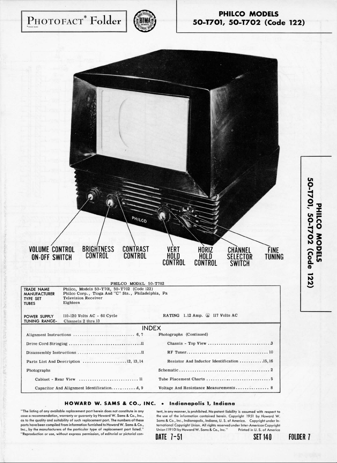
PHILCO
50-T701,
MODELS
5O-T702
(Code
122)
O
VOLUME
TRADE
MANUFACTURER
TYPE
TUBES
POWER
TUNING
Alignment
CONTROL
ON-OFF
SWITCH
NAME
Philco,
SET
Philco
Television
Eighteen
SUPPLY
110-120
RANGE-
Channels 2 thru
Instructions
Drive Cord Stringing
Disassembly Instructions
Parts
List
And
Description
Photographs
Cabinet - Rear
Capacitor
View
And
Alignment Identification
BRIGHTNESS
CONTROL
Models
50-T701,
Corp.,
Tioga
Receiver
Volts
AC - 60
13
And
CONTRAST
CONTROL
PHILCO MODEL 50-T702
50-T702 (Code 122)
"C"
Sts.,
Philadelphia,
Cycle
6, 7
11
11
12,
13,14
11
.4, 9
CONTROL
Pa
RATING
INDEX
Photographs
Schematic
Tube Placement Charts
Voltage
VERT
HOLD
CONTROL
1.12
Amp.
(Continued)
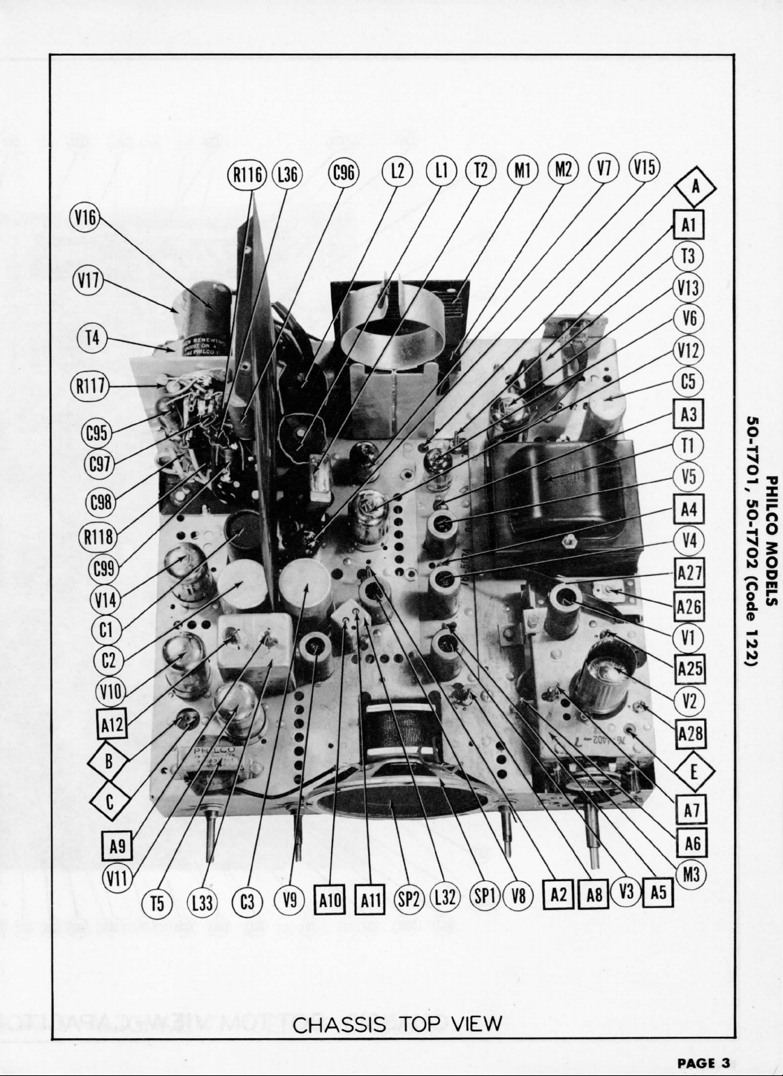
Chassis
- Top
View
RF
Tuner
Resistor
And
Inductor Identification
And
Resistance Measurements
HORIZ
HOLD
117
Volts
CHANNEL
SELECTOR
SWITCH
AC
..
FINE
TUNING
2
...10
.15,16
2
..5
N
?Z
SF
O
n
o
K>
HOWARD
"The listing
of any
case a recommendation, warranty
as
to the
parts have been compiled from information furnished
Inc.,
by the
"Reproduction
available replacement
quality
and
manufacturers
or
use, without
suitability
of the
of
such
particular type
express
part
or
guaranty
replacement part.
permission,
W.
herein does
by
Howard
of
SAMS & CO., INC. • Indianapolis
not
constitute
W.
The
to
Howard
replacement
of
editorial
in any
Sams & Co., Inc.,
numbers
of
these
W.
Sams & Co.,
part
listed."
or
pictorial
con-
tent,
in any
manner,
is
the
use of the
Sams & Co., Inc., Indianapolis,
ternational
Union(1910)
DATE
7-51
prohibited.
information contained herein. Copyright
Copyright
Union.
by
Howard
W.Sams
1,
Indiana,
All
rights
Indiana
No
patent
U. S. of
reserved
8.
Co.,
Inc."
liability
is
assumed with respect
1951
America. Copyright under
under
Printed
by
Inter-American
in U. S. of
SET
to
Howard
W.
In-
Copyright
America
140
FOLDER
7
Page 2
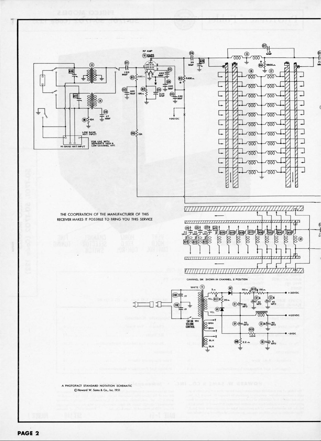
THE
COOPERATION
RECEIVER
MAKES
IT
POSSIBLE
OF THE
MANUFACTURER
TO
BRING
YOU
OF
THIS
THIS
SERVICE
CHANNEL
J_
re)|3-
T"
i
.^x
SWON
VOLUME
CONTROL
SW
SHOWN
IN
CHANNEL 2 POSITION
:®
o
Vv\
M
g
o
o
tH
»
S**
»
YEL®I
O
BRN
O
OBRN
|»-K
®:
J
fZ°"
it
(ff)^
®*
yy-J
=J50
B&
:««-
T
\
@
IOOK
•
2)V
1(S)A
40
l=t<
MFD
MFD
/
1500^1
®»^M'r0D
®Ad.
40
•
PAGE
2
A
PHOTOFACT STANDARD
©Howard
W.
NOTATION
Sams & Co.,
SCHEMATIC
Inc.
1951
Page 3
6BK
2ND
SOUND
®6AU6
IF
AMP
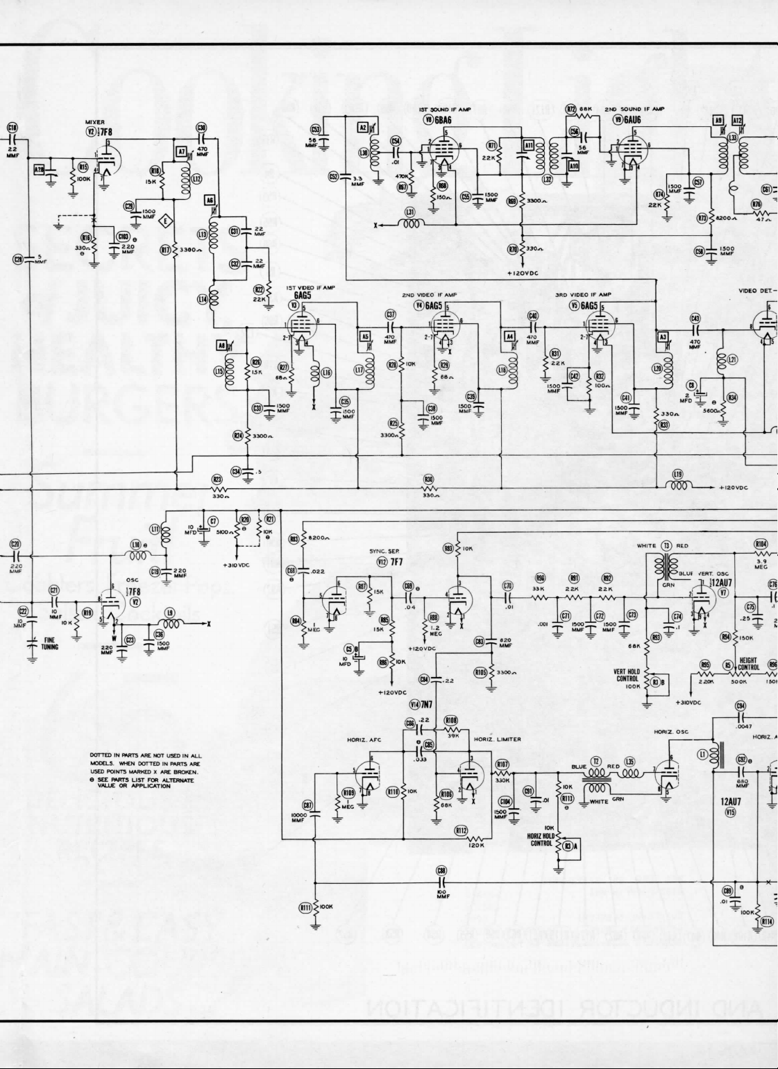
DOTTED
MODELS.
USED
8
SEE
VALUE
IN
fWTS
WHEN DOTTED
POINTS
MARKED
FWTTS
OR
APPLICATION
LIST
ARE
FOR
NOT
X ARE
USED
IN ALL
IN
PARTS
BROKEN.
ALTERNATE
ARE
Page 4
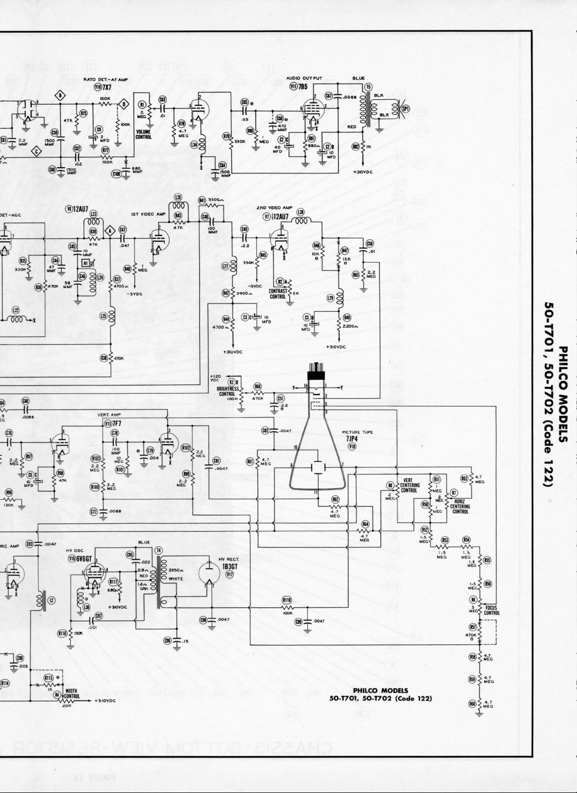
AUDIO
RATO
DET.-AFAUP
(§)7X7
._.
2.2
1500
-T-
®
r
MMF
MUF
~F
J
MFD
_[_
==
®7B5
OUTPUT
I
,
T
ff^-L
I®
SHI
PHILCO MODELS
5O-T7O1, 5O-T7O2 (Code 122)
Page 5
I
<
CO
co
CO
P
Q_
UJ
o
(Code 122)
50-T702
PHILCO MODELS
5O-T7O1,
Page 6
PAGE
4
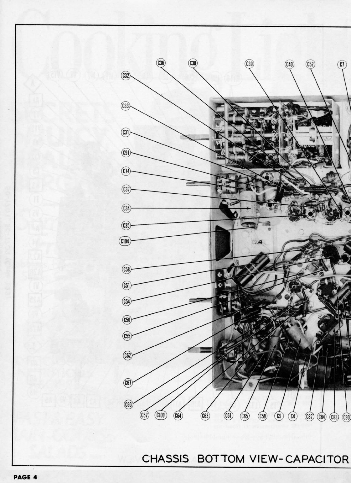
CHASSIS BOTTOM
VIEW-CAPACITOR
Page 7

(C42)
(Ml)
(a)
(C75)
(C43)
(CM)
Ul
O
ii
o
-
TS
"
I
Ul
p
So
32
10
O
^
o
o
p
;
AND
ALIGNMENT IDENTIFICATION
•
K)
K)
PAGE
9
Page 8

m
Ul
S
u
_
Q_
^
z
h-
cr
o
LJ
LJ
D
LJ
I-
CD
(Code 122)
5O-T7O2
PHILCO MODELS
50-T701,
Page 9

Turn
the
channel switch
response
curve
Connect
the
DUMMY
ANTENNA
.
001MFD
"
Direct
"
Use
frequency
DUMMY
ANTENNA
.
001MFD
Connect
two
the
schematic.
The
sweep generator
Set the
fine
DUMMY
ANTENNA
Two
120S!
carbon
resistors
to a
switch
SWEEP
GENERATOR
COUPLING
to Pin 1
(V5).
Low
to Pin 1
(V4).
Low
to Pin 1
(V3).
Low
to an
unground-
floating
side
to
signal
SWEEP
GENERATOR
COUPLING
to Pin 1
(V5).
chassis.
100KS2
output
control
to the
SIGNAL
GENERATOR
COUPLING
antenna
terminals
in
each
channel
to
(grid)
side
(grid)
side
(grid)
side
with
(grid)
Low
(+
1% )
lead should
mid-position
lead.
another
changes,
synchronized sweep voltage
High
side
of
6AG5,
to
chassis.
High
side
of
6AG5,
:o
chassis.
High
side
of
6AG5,
.0
chassis.
ligh
side
ed
tube shield
V2).
Low
chassis.
modulated
High
side
of
6AG5,
side
to
matched
tuning
Across
with
120SJ
ALIGNMENT
ALIGNMENT
which
from
GENERATOR
FREQUENCY
Not
24MC
(10MC
Not
24MC
60 ^ modulation
GENERATOR
FREQUENCY
22.
IMC
(450KC
resistors
be
SIGNAL
GENERATOR
FREQUENCY
59.
65.
71.75MC
81.75MC
87.
179.
185.
191.
197.
203.75MC
209.
215.75MC
causes
channel.
the
SWEEP
used
SWP)
used
SWEEP
SWP)
in
terminated
of its
75MC
75MC
75MC
75MC
75MC
75MC
75MC
75MC
signal
series
INSTRUCTIONS-READ
no
erroneous indications.
generator
MARKER
GENERATOR
FREQUENCY
22.
IMC
14001.
Mod.)
22.
SMC
26. 5MC
22.
IMC
24MC
24.
IMC
28.
IMC
(400 % Mod.
23.6MC
24.25MC
26.25MC
26. 6MC
GENERATOR
FREQUENCY
range.
SOUND
and
450KC
MARKER
22.
IMC
OSCILLATOR
from
Point B to
with
its
characteristic impedance, usually
CHANNEL
2
3
4
5
6
7
8
9
10
11
12
13
INSTRUCTIONS
CAREFULLY
VIDEO
IF
to the
horizontal
CHANNEL
See
Instructions
Above
"
IF
ALIGNMENT
sweep.
Use 120 ^ sawtooth voltage
CHANNEL
See
instructions
above
Video
IF
Alignment
ALIGNMENT
chassis.
CONNECT
VTVM
)C
probe
to
Common
to
ALIGNMENT
To
check
input
CONNECT
Vert. amp.
A^>
Low
chassis.
CONNECT
Vert. amp.
<g>.
Low
chassis.
Vert. amp.
^>
Low
chassis.
The
Point
<^.
Point
Q/.
BEFORE
ATTEMPTING
for
erroneous indications, turn
of the
oscilloscope
SCOPE
to
Point
side
to
SCOPE
to
Point
side
to
to
Point
side
to
junction
of
these
50
ADJUST
A13
A14
A15
A16
A17
A18
A19
A20
A21
A22
A23
A24
ADJUST
Al,
A2
A3
A4
A5
A6
A7,
A8
in
ADJUST
A9,
A10,
All
A12
ohms.
Adjust
ing
will
ALIGNMENT
for
horizontal deflection.
Adjust
scope.
Adjust
Adjust
Adjust
Adjust
Adjust
If
necessary
proper
scope
for
horizontal deflection.
Disconnect
for
maximum
figure
Reconnect
occurs
figure
amplitude
two
resistors
for
zero
reading. A positive
be
obtained
the
fine
for
MINIMUM
for
response
for
response
for
response
for
MINIMUM
for
response
retouch
response.
stabilizer
amplitude
5.
capacitor
at
center
6.
SLIGHTLY
and
straightness
is
alignment Point
REMARKS
on
either
tuning
control.
REMARKS
400 ^ indication
curve similar
curve similar
curve
similar
400
"a
indication
curve
similar
A3, A4, and A5 for
REMARKS
capacitor
and
symmetry
C9.
Adjust
of
crossover
retouch
of
D as
and
side
of the
If the
to
figure
to
figure
to
figure
on
to
figure
C9.
Adjust
A12 so 4.
lines
as per
A9 for
maximun
crossover
shown
negative
correct
on
scope.
as per
5MC
lines.
on
read-
setting.
1.
2.
3.
4.
PAGE
6
FIG.I
FIG.2
FIG.3
FIG.4
Page 10

ALIGNMENT
The
sweep
generator
Across
with
120S2
output lead should
IF
coil. This
SWEEP
GENERATOR
COUPLING
antenna
terminals
in
each
lead.
Short
the
DUMMY
ANTENNA
Two
120S!
carbon
resistors
first video
11.
12.
be
may be
SWEEP
GENERATOR
FREQUENCY
57MC
(12MC SWP)
8
SMC
(12MC
213MC
(10MC
terminated
done
by
SWP)
SWP)
INSTRUCTIONS
RF
its
characteristic
CHANNEL
2
6
U
ALIGNMENT
of
solder
Vert. amp.
chassis.
impedance, usually
into
E
. Low
with
inserting a piece
MARKER
GENERATOR
FREQUENCY
54MC
60MC
82MC
88MC
210MC
216MC
the
hole
CONNECT
SCOPE
to
side
adjacent
Point
to
CCONTJ
50
ohms.
to the IF
adjusting
ADJUST
A25
Adjust
A26
A27,
A28
Adjust
Recheck
within
compromise
be
trimmer,
for
response curve similar
for
response
all
channels
the
limits
of
required.
A25, A26,
A7.
REMARKS
"
curve
to see
of
figure
A27 and A28 may
similar
that they fall
7. If not
to
to
slight
figure
figure
7.
7.
FIG.5
FIG.
6
FIG.7
Ui
O
Q.
n
io
to
PAGE
7
Page 11

MEASUREMENTS
RESISTANCE
AND
VOLTAGE
.sn
PIN 14
•
9
Pin
8
Pin
lOKn
7
Pin
on
esn
ioon
6
Pin
i660n
i330n
ts.iKn
5
Pin
»4Kn
tsson
on
4
Pin
.in
.in
3
Pin
2
Pin
1
Pin
Tube
Item
9
Pin
8
Pin
7
Pin
6
Pin
5
Pin
on
1000
810KS1
6AG5
V 1V
.6VDC
110VDC
95VDC
sson
14KS2
on
.m
esn
100KJJ
800M
5
7F8
BAG
2
V 3V
§-5.5VDC
.1VDC
0V
185VDC
115VDC
0V
115VDC
READINGS
RESISTANCE
on
on
5.6Kn
5Kn
een
ioon
lOKn
t330Kn
i.m
*330n
330Kn
T8.2Kn
«33on
.in
i.sn
on
.in
ma
tugg
6AG5
4
.5VDC
120VDC
I20VDC
.in
.in
on
.in
.in
on
on
loon
HMeg
168Kn
22KS2
t!2Kn
T350KSJ
300KSJ
t
6AG5
12AU7
12AU7
6
V
V5
V7
OV
OV
2.1VDC
12VDC
1VDC
2VDC
-1.3VDC
-.2VDC
115VDC
280VDC
VAC
3
3VAC
115VDC
6.
6.
on
.in
ononon
on
ison
*3.6Kn
i3.6Kn
.in
on
on
470KO
6BA6
V8
1.6VDC
85VDC
85VDC
680g
on
Inf.
»7.5Kn
47Kn
ii4Kn
IMeg
i7.5Kn
Inf.
Int.
IMeg
.in
on
il.2Mee
Inf.
on
4.7Meg
tmn
tiSKn
on
t330Kn
Tl.SKSi
ononon
.10
68Kn
on
.m
7X7
6AU6
7B5
7F7
12
10
V9
V
V
V 1 1
3VAC
nv
6.
ov
-15VDC
0V
20VDC
0V
-.8VDC
55VDC
0V
46VDC
-.5VDC
0V
65VDC
-.7VDC
on
47Kn
SMeg
18.
tlSKO
2.2Mee
IMeg
lOMeg
68Kn
5Mee
18.
isoKn
.in
.in
7N7
7F7
13V 14V 15
V
ov
ov
5VDC
0V
470VDC
115VDC
.1VDC
-1.4VDC
.in
TOP CAP
PIN 11
T3.3Kn
*5.8Meg
son
on
Inf.
150Kn
teson
teson
.in
M.
6V6GT
16V 17
V
1.4VDC
0V
0V
-50VDC
SMeg
PIN 10
»4.8Meg
16.
PIN 9
*iooxn
8
PIN
*5.8Meg
7
SMeg
PIN
f 6.
*4.8Meg
5
PIN
14Meg
17Meg
RESISTANCE
2.2Meg
INFINITE
8
470Kn
THRU
1
PINS
«.5n
1B3GT
7JP4
V18
3VAC
16.
PIN 14
I
1
5, 7, 8, 9, 10, 11
PINS
MEASURE
volt-
to the
for
volts
LINE
LINE
1 AND 14 OF V18
LINE
120VDC
-3VDC
PIN 7 OF V17
310VDC
FROM
MEASUREMENTS TAKEN WITH PICTURE TUBE REMOVED
MEASURED FROM
MEASURED
MEASURED ACROSS PINS
MEASURED FROM
MEASURED FROM
i
ALL
t
•
1
»
117
at
voltage maintained
readings.
Line
age
4.
1,000
20,000
at
are at
measured
Voltage
AC
measurements
volt;
per
Voltage
ohms
DC
1.
both minimum
given.
minimum.
are
at
vary according
set
controls,
may
service
controls
readings
of the
panels
maximum readings
setting
and
Front
Where
5.
6.
com-
direc-
pin to
stated.
clockwise
socket
in a
from
otherwise
socket.
are
counted
of
unless
are
values
bottom
negative
on
numbers
mon
tion
Measured
Pin
3.
2.
2.2n
i8Kn
ti2Kn
t2.5Kn
on
on
on
looxn
t!2Kn
t2.5Kn
12AU7
6.3VAC
ov
-24VDC
170VDC
270VDC
0V
o
4
Pin
READINGS
3
Pin
VOITAGE
2
Pin
1
Pin
Tube
Item
m
CO
6.3VAC
0V
.6VDC
-.5VDC
6AG5
V 1V2
3VAC
1.2VDC
6.
0V
0V
6.3VAC
6.3VAC
6.3VAC
6.3VAC
0V0V.1VDC
3VAC6. 3VAC
100VDC
0V
6.
0V
0V
0V
-.6VDC
0V
3VAC
.1VDC
6.
.5VDC
-.8VDC
-14VDC
1VDC
-.4VDC
-4.4VDC
-.5VDC
0V
7F8
6AG5
6AG5
6AG5
5
3
V
V 4V
0V
0V
90VDC
VAC
3
0V
170VDC
12AU7
V6
-.4VDC
45VDC
12AU7
7
V
6BA6
V 8V9
6.
7X7
6AU6
10
V
265VDC
255VDC
0V
7B5
Vll
-.6VDC
190VDC
235VDC
0V0V0V
VAC
3
6.3VAC
6.
7F7
7F7
12
13
V
V
-3.5VDC
0V
16VDC
0V
-3VDC
3VAC
6.
155VDC
245VDC
7N7
12AU7
15
V
V14
* DO NOT
270VDC
TUBE REMOVED
270VDC
MEASURE
6.3VAC
DO NOT
«
0V
6V6GT
1B3GT
V16
V17
V18
0V.
PICTURE
|
VOLTMETER
1 AND 14 OF
110VDC
PINS
6.3VAC
•
ACROSS
MEASURE
7IP4
MEASUREMENTS TAKEN WITH
MEASURED
TAKEN WITH VACUUM TUBE
DO NOT
18
ALL
V
Page 12

RF
TUNER-RIGHT
SIDE
PAGE
1O
RF
TUNER-LEFT
SIDE
Page 13

WIDTH
HEIGHT
CONTROL
FOCUS
HORIZ
VERT
CONTROL CONTROL CENTERING CENTERING
CONTROL
CONTROL
h
05
WQ
~
o
n
jn
CABINET-REAR
DISASSEMBLY
1.
Remove seven push-on type control knobs.
2.
Remove
three
3.
Remove
four
NOTE:
FOR
AS
PICTURE TUBE REMOVAL,
OUTLINED ABOVE.
phillips head
5/16"
hex
head
TUNING
3
TURNS
screws
bolts
from
from
GANG
VIEW
INSTRUCTIONS
rear
cover.
Remove
rear
cover.
chassis.
Remove
chassis.
IT IS
NECESSARY
FULLY
TO
CLOSED
REMOVE
THE
CHASSIS
to
o
FINE
TUNING
DRIVE CORD
STRINGING
PAGE
11
Page 14

V18
Cl
C2A
C4
C5A
C6
C7
C8
C9
CIO
Cll
C12
CIS
C14
CIS
C16
C17
CIS
CI9
C20
C21
C22
C23
C24
C25
C26
C27
C28
C29
C30
C31
C32
C33
C34
C49
C50
C51
C52
C53
C54
C55
C56
C57
C58
C59
C60
C61
C62
C63
VI
V2
V3
V4
V5
V6
V7
V8
V9
V10
Vll
V12
V13
V14
V15
V16
V17
ITEM
C3A
C35
C36
C37
C38
C39
C40
C41
C42
C43
C44
C45
C46
C47
C48
ITEM
No.
No.
ITEM
No.
B
C
B
C
B
C
HF
Amplltier
Converter
1st
Video
2nd
Video
3rd
Video
Video
Detector
AGC-lst
2nd
Video Amp.
Vertical
1st
Sound
2nd
Sound
Ratio
Detector
AF
Amplifier
Audio
Output
Sync.
Separator
Vertical
Horiz.
Limiter
Horiz.
Oscillator
Horiz.
Amplifier
H.
V.
Oscillator
H.V.
Rectifier
PHILCO
PART
7JP4
RATING
CAP.
50
40
10
40
40
10
10
50
80
10
10
2
10
2
2
27
220
220
220
220
220
39
1.5
22
220
220
10
10
220
220
39
22
39
5
1500
470
22
22
1500
.5
1500
1500
470
1500
1500
470
1500
1500
470
47
10
56
.047
100
.22
.01
.22
3.3
56
.01
1500
56
1500
1500
1500
1500
2.2
.02
.01
USE
IF
Amp.
IF
Amp.
IF
Amp.
Video Amp.
Osc.
IF
Amp.
IF
Amp.
Amplifier
AFC -
Horiz.
No.
VOLT
250
450
450
50
450
450
450
250
250
250
250
50
450
50
50
120
200
400
600
400
100
200
400
-
-
-
-
REPLACEMENT
Capacity
and
PHILCO
PART
30-2568-32
30-2570-36
30-2568-32
30-2570-37
30-2417-7
30-2417-6
30-2417-7
30-2417-7
62-215001011
62-147001001
62-022009001
62-022009001
62-215001011
61-0133
62-215001011
62-215001011
62-147001001
62-215001011
62-215001011
62-147001001
62-215001011
62-215001011
62-147001001
30-1224-2
62-010009001
62-056409001
62-110009001
45-3500-9
61-0120
30-1224-30
62-056409001
60-0120
62-215001011
60-056409001
62-215001011
62-215001011
62-215001011
62-215001011
30-1221-4
61-0108
61-0120
REPLACEMENT
PHILCO
PART
6AG5
7F8
6AG5
6AG5
6AG5
12AU7
12AU7
6BA6
6AU6
7X7
TBS
7F7
7F7
7N7
12AU7
6V6GT
1B3GT
SYLVANIA
PART
No.
7JP4
values
Paper
No.
TUBES
(SYLVANIA
DATA
No.
6AG5
7F8
6AG5
6AG5
6AG5
STANDARD
REPLACEMENT
12AU7
12AU7
6BA6
6AU6
7X7
7B5
7F7
7F7
7N7
12AU7
6V6GT
1B3GT
CATHODE-RAY
DATA
THOMAS
PART
No.
given
AEROVOX
PART
No.
AF88J2K
AF822X
E3A60
AF1622J
E26E6
PRS450/10
E26E6
E26E6
SI220
SI220
SI220
SI220
SI220
SI39
SI1.5NPO
SI22
SI220
SI220
SI10NPO
SI10NPO
SI220
SI220
SI39
SI39
SI5NPO
SI1500
SI470
SI1500
P288-5
SI1500
SI1500
SI470
SI1500
SI1500
SI470
SI1500
SI1500
SI470
SI47
SI10
P288-047
snoo
P488-22
P688-01
P488-22
S13.3NPO
P488-01
SI1500
SI56
SI1500
SI1500
SI1500
SI1500
P488-02
P488-01
in the
and in
Capacitors,
DMA
BASE
TYPE
7BQ
8BW
7BD
7BD
7BD
9A
9A
7BK
7BK
BBZ
6AE
SAC
SAC
SAC
9A
7AC
3C
RTMA
BASE
TYPE
14G
CAPACITORS
rating
column
mmfd.
PART
No.
TCZ-27
D6-221
D6-221
D6-221
D6-221
D6-221
D6-390
TCZ-1.5
D6-220
D6-221
D6-221
TCZ-10
TCZ-10
D6-221
D6-221
D6-390
TCZ-22
D6-390
D6-152
D6-471
TCZ-22
TCZ-22
D6-152
D6-152
D6-152
D6-471
D6-152
D6-152
D6-471
D6-152
D6-152
D6-471
D6-470
D6-100
TCZ-56
DF-503
D6-101
D6-103
TCZ-3.3
TCZ-56
D6-103
D6-152
D6-560
D6-152
D6-152
D6-152
D6-152
TCZ-2.2
DF-203
D6-103
for
DATA
CORNELLPART
JPT4145VK
UPT5030
(
UP8025
BRD-2225
1
BBR2-50T
BR1045A
BBR2-50T
BBR2-50T
W5D15
GT2P5
1W5D15
1W5D15
5R5T5
1W5D15
1W5D15
5R5T5
1W5D15
1W5D15
5R5T5
5W5Q5
5W5Q1
PTE4S5
5W5T1
GT4P25
PTE6S1
GT4P25
PTE4S1
1W5D15
5R5Q5
1W5D15
IW5D15
IW5DI5
IW5D15
PTE4S2
PTE4S1
REPLACEMENT
CENTRALAB
or
Equivalent)
TUBE
are in
Mica
and
DUBILIER
No.
NPOK-270
GP2K-221
GP2K-221
GP2K-221
GP2K-221
GP2K-221
GP1K-390
NPOK-1R5
GP1K-220
GP2K-221
GP2K-221
NPOK-100
NPOK-100
GP2K-221
GP2K-221
GP1K-390
NPOK-220
GP1K-390
NPOK-050
GP2L-152
GP2K-471
NPOK-220
NPOK-220
GP2L-152
GP2-333-103
GP2L-152
GP1K-560
GP2L-152
GP2L-152
GP2L-152
GP2L-152
NPOK-2R2
GP2-333-103
mfd.
Ceramic
ERIE
PART
No.
GP2L-152
GP2L-152
GP2K-471
GP2L-152
GP2L-152
GP2K-471
GP2L-152
GP2L-152
GP2K-471
GP1K-470
GP1K-100
NPO-333-560
GP1K-101
GP2-333-103
NPOK-3R3
NPO-333-560
NOTES
for
Electrolytic
Capacitors.
SPRAGUE
PART
TVL-3754
TVL-1522
H1113
TVA-130I
TVA-1705
TVA-1301
TVA-1301
19C13
19C13
19C13
19C13
19C13
19C23
19C13
19C13
19C3
19C3
19C13
19C13
29C12
29C8
19C15
29C12
29C12
29C8
2TM-P5
29C8
29C8
19C15
29C8
29C8
19C15
29C8
29C8
19C15
19C25
19C19
2TM-S47
19C11
4TM-P22
6TM-S1
4TM-P22
4TM-S1
29C8
29C8
29C8
29C8
29C8
2TM-S2
4TM-S1
NOTES
IDENTIFICATION
INSTALLATION
No.
Filter
.
Filter
•
Audio Output Dec.
A
Audio Output Cathode
.
Filter
•
Decoupling
A
Decoupling
Filter
•
Filter
A
Decoupling
Vert.
Amp. Cathode
Bias
Filter
Decoupling
Video
Del.
Stabilizing
Fixed
Trimmer
RF
Coupling
AGC
Filter
RF
Amp. Cathode
RF
Amp. Cathode
RF
Amp.
HF
Coupling
RF
Coupling
RF
Coupling
Osc.
Plate
Osc.
Feedback
Osc. Grid
Fixed
Trimmer
Fil.
Bypass
Fil.
Bypass
Fixed
Padder
Fixed
Padder
Fixed
Padder
Osc. Coupling
Mixer
Plate
IF
Coupling
Fixed
Trimmer
Fixed
Trimmer
AGC
Filter
AGC
Filter
1st
Video
Fil.
Bypass
IF
Coupling
AGC
Filter
2nd
Video
IF
Coupling
3rd
Video
3rd
Video
IF
Coupling
AGC
Filter
Sound
IF
Fixed
Trimmer
Video Coupling
Video Coupling
Video
Coupling
Video Coupling
Picture
Sound
IF
Fixed
Trimmer
Sound
IF
1st
Sound
Sound
IF
2nd
Sound
RF
Bypass
Diode Load
Diode
Load
Balancing
Audio
Coupling
Audio
Coupling
AND
Cathode
Cap
Screen
Decoupling
Cap
Decoupling
IF
Dec.
IF
Dec.
IF
Dec.
IF
Cathode
Coupling
Tube
Cathode
Coupling
Coupling
IF
Dec.
Coupling
IF
Dec.
Cap
Cap
Cap
CODES
NOTES
PARTS LIST
AN
CAPACITi
AEROVOX
PART
No.
P488-25
P688-004
Part # 61-0125
Part * 61-012
Part » 61-006
Part*
61-0170
Part # 61-0119
application
Part * 60-1082!
Part # 30-46
REPLAC
CENTR
PART
D6-1S
DF-5
D6-4
D6-6
DF-2
DF-5
D6-K
D6-K
D6-1!
D6-H
DF-1
DFD6-
D6TV6
TV6
D6-1
D6-]
D6-1
D6-:
D6-I
D6-I
TV6
TV6
D6-1
TV6
TV6
D6-<
D6-1
D6-1
D6-;
D6-1
and C
i
C64
C65
C66
C67
C68
C69
C70
C71
C72
C73
C74
C75
C76
C77
C78
C79
C80
C81
C82
C83
C84
C85
C86
C87
C88
C89
C90
C91
C92
C93
C94
C95
C96
C97
C98
C99
C100
C101
C102
C103
C104
ITEM
No.
CAP.
1500
.05
470
.0068
.022
.04
.01
.001
1500
1500
.1
.25
.1
.0068
100
.004
.0068
.0047
.
0047
820
.22
.033
.22
10000
100
.01
.003
.
680
.0047
.0047
.022
.15
.001
.0047
.0047
680
.01
.01
220
1500
* Not
t
Some
t
Some
ft
Some
tt
Some
••
Some
1
Some
11
Some
•
Some
RATING
01
VOLT
600
1000
600
400
400
600
400
400
400
1600
500
400
1600
6000
6000
500
200
400
400
500
400
600
400
500
6000
6000
1000
600
600
6000
6000
400
400
used
models
models
models
models
models
models
models
models
in all
use .
use
PHILCO
PART
No.
62-215001011
62-147001001
61-0174
61-0120
45-3500-5
62-215001011
62-215001011
45-3500-8
61-0122
61-0113
61-0127
62-110009001
45-3500-17
61-0127
30-4661-2
30-4661-2
60-10825401
61-0125
61-0125
61-0120
62-110009001
61,0120
61-0120
30-4661-2
30-4661-2
61-0118
61-0193
45-3500-5
30-4661-2
30-4661-2
60-0120
60-0120
62-2)5001011
models.
use .
25MFD . Mfgrs.
use .
047MFD . Mfgrs.
use
.002MFD.
use .
05MFD . Mlgrs.
03MFD. Mfgrs.
use .
015MFD
820MMF.
use .
004TMFD.
SI1500
P688-05
SI470
P1088-0068
P688-022
P688-04
P488-01
P688-001
SI1500
SI1500
P488-1
SI1500
Mlgrs.
in
this
Mfgrs.
Mfgrs.
P488-1
P1688-006S
1468-0001
P1688-0068
6089-005
6089-005
1464-0008
P488-22
P488-033
P488-22
1467-01
SHOO
P488-01
P688-003
P488-01
1479-0007
6089-005
6089-005
P1088-022
684-15
P688-001
6089-005
6089-005
SI680
P488-01
P488-01
SI220
cor
RATING
ITEM
No.
RESIST-
WATTS
ANCE
End
shaft
RATING
RESISTANCE
5%
5%
5%
20%
20%
i
2
1
k
i
3
1
1
2
i
parts
to
WATTS
to
duplicate
2
2
1
2
I
1
2
i
2
2
1
1
f
|
5
1
2
2
i
2
i
2
2
k
\
2
2
1
2
2
R1A
2Meg
Shaft
B
Switch
C
5000
R2A
100KS!
B
H3A
ten
100KS!
B
C
Shaft
R4
20KSJ
R5A
500KSJ
Shaft
B
R6A
3Meg
Shaft
B
2Meg
R7A
Shaft
B
R8A
2Meg
B
Shaft
Additional
Fashion
ITEM
No.
10KS!
H9
lOKf!
RIO
330!!
Rll
R12
100Q
3300S!
R13
esoon
R14
100KS!
R15
330SI
R16
3300S2
R17
15KS!
R18
10KS!
H19
sioon
R20
t
R21
R22
R23
R24
R25
R26
R27
R28
R29
R30
R31
R32
R33
R34
R35
loxn
22KH
sson
3300SJ
3300!!
15KO
NO
lOKn
MB
330Si
22KS1
loon
330S!
5600SJ
330KS!
PHILCO
PART
No.
33-6566
Not
req.
Not
req.
33-5546-11
33-5563-2
33-5546-18
33-5565-2
Not
req.
33-5565-4
Not
req.
33-5565-3
Not
req.
33-5565-3
Not
req.
be
used
with " Concentrikit"
original.
PHILCO
PART
33-1335-18
66-3108340
66-3228340
66-1338340
66-2338340
66-2338340
66-3158340
66-0688340
66-3108340
66-0688340
66-1338340
66-3228340
66-1108340
66-1338340
66-2568340
66-4338340
REPLACEMENT
/
1
(,
REPLACEMENT
No.
IRC
PART
No.
Q13-139
Not
req.
76-1
Concentrikit'S
/
B1I-116 j {
Bll-128
f(
E-I87
i)
Qll-133
Not
req.
Qll-140
TQ
Qll-139
TQ
Qll-139
TQ
DATA
BTS-iOK
BTS-330-5%
BTS-100
BTS
BTS-330
BTS-3300-5%
1
3/4A-5000
BTS-IOK
BTS-330
BTS-3300
BTS-3300
BTS-330
BTS-22K
BTS-100
BTS-330
BTS-5600
BTS-330K
DATA
f
IRC
PART
No.
-3300-5%
CLARI
PAR!
AG-66
FS-3
SWB
RTV-2
RTV-1
58-201
AG-58
FKS-1,
AM-84
RN-3
AM-83
HN-3
AM-83
RN-3
RES
PAGE
12
Page 15

r
Electrolytic
c
Capacitors.
SPRAGUE
PART
No.
TVL-3754
TVL-1522
B1113
TVA-1301
TVA-1705
TVA-1301
TVA-1301
19C13
19C13
19C13
19C13
19C13
19C23
19C13
19C13
19C3
19C3
19C13
19C13
29C12
29C8
19C15
29C12
29C12
29C8
2TM-P5
29C8
29C8
19C15
29C8
29C8
19C15
29C8
29C8
19C15
19C25
19C19
2TM-S47
19C11
4TM-P22
6TM-S1
4TM-P22
4TM-S1
29C8
29C8
29C8
29C8
29C8
2TM-S2
4TM-S1
IDENTIFICATION
AND
INSTALLATION
Filter
.
Filter
•
Audio
Output Dec.
A
Audio
Output
.
Filter
•
Decoupling
A
Decoupling
Filter
>
Filter
A
Decoupling
Vert.
Amp. Cathode
Bias
Filter
Decoupling
Video
Det. Cathode
Stabilizing
Cap
Fixed
Trimmer
RF
Coupling
AGC
Filter
RF
Amp. Cathode
RF
Amp. Cathode
RF
Amp.
Screen
RF
Coupling
RF
Coupling
RF
Coupling
Osc.
Plate
Decoupling
Osc.
Feedback
Osc. Grid
Cap
Fixed
Trimmer
Fil.
Bypass
Fil.
Bypass
Fixed
Padder
Fixed
Padder
Fixed
Padder
Osc. Coupling
Mixer
Plate
IF
Coupling
Fixed
Trimmer
Fixed
Trimmer
AGC
Filter
AGC
Filter
1st
Video
IF
Fil.
Bypass
IF
Coupling
AGC
Filter
2nd
Video
IF
IF
Coupling
3rd
Video
IF
3rd
Video
IF
IF
Coupling
AGC
Filter
Sound
IF
Coupling
Fixed
Trimmer
Video Coupling
Video Coupling
Video
Coupling
Video
Coupling
Picture
Tube
Sound
IF
Coupling
Fixed
Trimmer
Sound
IF
Coupling
1st
Sound
IF
Sound
IF
Coupling
2nd
Sound
IF
HF
Bypass
Diode
Load
Cap
Diode
Load
Balancing
Cap
Audio
Coupling
Audio
Coupling
CODES
NOTES
Cathode
Decoupling
Dec.
Dec.
Dec.
Cathode
Cathode
Dec.
Dec.
Cap
PARTS
RATING
ITEM
CAP.
No.
C64
1500
.05
C65
C66
470
C67
.0068
.022
C68
.04
C69
C70
.01
C71
.001
C72
1500
1500
C73
.1
C74
.25
C75
.1
C76
C77
.0068!
100
C78
.004
C79
C80
.0068
.0047
C81
.0047
C82
C83
820
.22
C84
C85
.033
.22
C86
C87
10000
CSS
100
.01
C89
.003
C90
.01
C91
680
C92
.0047
C93
C94
.
0047
C95
.022
.15
C96
C97
.001
.0047
C98
.0047
C99
680
C100
C101
.01
C102
.01
C103
220
C104
1500
Not
used
Som
t
t Som
tt
Som
tt
Som
** Som
1 Som
If
Som
* Som
RATING
ITEM
No.
RESIST-
ANCE
R1A
2Meg
Shaft
B
Switch
C
5000
R2A
100KB
B
10KB
R3A
100KB
B
C
Shaft
2
OKU
500KB
Shaft
B
SMeg
Shaft
B
2Meg
Shaft
B
2Meg
Shaft
B
((
Additional
#
Fashion shaft
ITEM
No.
RESISTANCE
IOKB
IOKB
330B
100B
330012
6800B
100KB
330B
3300B
15KB
10KB
SIOOB
10KB
22KB
330B
3300B
3300B
16KB
NO
10KB
MB
330B
22KB
100B
330B
5600B
330KB
End
RATING
5%
5%
5%
20%
20%
R4
R5A
R6A
R7A
R8A
R9
RIO
Rll
R12
R13
R14
R15
R16
R17
R18
R19
R20
t
R21
R22
R23
R24
R25
R26
R27
R28
R29
R30
R31
R32
R33
R34
R35
VOLT
600
1000
600
400
400
600
400
400
400
1600
500
400
1600
6000
6000
500
200
400
400
500
400
600
400
500
6000
6000
1000
600
600
6000
6000
400
400
in all
models
models
models
models
models
models
models
models
WATTS
parts
1
2
I
1
\
z
I
z
1
PHILCO
PART
62-215001011
62-147001001
61-0174
61-0120
45-3500-5
62-215001011
62-215001011
45-3500-8
61-0122
61-0113
61-0127
62-110009001
45-3500-17
61-0127
30-4661-2
30-4661-2
60-10825401
61-0125
61-0125
61-0120
62-110009001
61,0120
61-0120
30-4661-2
30-4661-2
61-0118
61-0193
45-3500-5
30-4661-2
30-4661-2
60-0120
60-0120
62-215001011
models
use
.25MFD . Mfgrs.
use .
047MFD . Mfgrs.
use .
002MFD. Mfgrs.
use
-05MFD . Mfgrs.
use .
03MFD. Mfgrs.
use .
015MFD
use
820MMF. Mfgrs.
use .
004TMFD.
PHILCO
PART
33-6566
Not
Not
33-5546-11
33-5563-2
33-5546-18
33-5565-2
Not
33-5565-4
Not
33-5565-3
Not
33-5565-3
Not
to be
used with " Concentrikit".
to
duplicate
WATTS
2
1
Z
1
i
1
2
I
1
L
t
I
5
i
2
2
1
Z
1
Z
i
z
\
No.
in
REPLACEMENT
No.
req.
req.
1
req.
req.
req.
req.
original.
REPLACEMENT
PHILCO
PART
No.
33-1335-18
66-3108340
66-3228340
66-1338340
66-2338340
66-2338340
66-3158340
66-0688340
66-3108340
66-0688340
66-1338340
66-3228340
66-1108340
66-1338340
66-2568340
66-4338340
LIST
CAPACITORS
AEROVOX
PART
No.
SI1500
P688-05
SI470
P1088-0068
P688-022
P688-04
P488-01
P688-001
SI1500
SI1500
P488-1
P488-25
P488-1
P1688-0068
1468-0001
P688-004
P1688-0068
6089-005
6089-005
1464-0008
P488-22
P488-033
P488-22
1467-01
SHOO
P488-01
P688-003
P488-01
1479-0007
6089-005
6089-005
P1088-022
684-15
P688-001
6089-005
6089-005
SI680
P488-01
P488-01
SI220
SI1500
Part # 61-0125
Part # 61-0122
Part # 61-0062
Part # 61-0170in
Part # 61-0119
this application
Part # 60-10825401
Mfgrs.
Part # 30-4661-2
IRC
PART
No.
Q13-139
Not
req.
76-1
Concentrikit^
/
B1I-116 4 [
/
Bll-128 i (
E-187
i )
I
Qll-133
Not
req.
Qll-140
T«
Qll-139
TQ
Qll-139
TQ
BTS-iOK
BTS-330-5%
BTS-100
BTS-3300-5%
BTS-330
BTS-3300-5%
1
3/4A-5000
BTS-IOK
BTS-330
BTS-3300
BTS-3300
BTS-330
BTS-22K
BTS-100
BTS-330
BTS-5600
BTS-330K
AND
REPLACEMENT
CENTRALAB
PART
D6-152
DF-503
D6-471
D6-682
DF-203
DF-503
D6-103
D6-102
D6-152
D6-152
DF-104
D6-152
and C90 is not
CONTROLS
DATA
CLAROSTAT
AG-66-Z
FS-3
SWB
RTV-283
RTV-76
58-20K
AG-58-S
FKS-1/4
AM-84-S
RN-3
AM-83-S
RN-3
AM-83-S
RN-3
RESISTORS
DATA
IRC
PART
No.
DESCRIPTIONS
CCONT.J
DATA
CORNELL-
DUBILIER
No.
PART
W5D15
PTE6S5
R5T5
DSD
PTE6S2
PTE6S4
PTE4S1
PTE6D1
1W5D15
1W5D15
PTE4P1
GT4P25
PTE4P1
DF-104
PTE16D7
D6-101
5W5T1
PTE6D4
D6-402
PTE16D7
TV6-502
PTE60D5
TV6-502
PTE60D5
2R5T8
GT4P25
PTE6S3
GT4P25
D6-103
1D3S1
5W5T1
D6-101
PTE4S1
D6-103
D6-302
PTE6D3
PTE4S1
D6-103
1W5T7
D6-681
PTE60D5
TV6-502
TV6-502
PTE60D5
PTE16S2
D6-102
PTE6D1
TV6-502
PTE60D5
TV6-502
PTE60D5
1W5T7
D6-681
D6-103
PTE4S1
D6-103
PTE4S1
D6-221
1W5D15
in
this
application.
in
this
application,
in
this application.
this
application.
in
this
application,
in
this
in
this
PART
No.
SBB-675
#
AN-59
AK-1
AN-84
AK-19
AN-75
AK-19
AN-75
AK-19
ALL
RESISTORS
Antenna
AGC"
Network
RF
Amp. Grid
RF
Amp. Cathode
RF
Amp.
RF Coil Shunt
Mixer Grid
Mixer Cathode
Mixer
Decoupling
Converter
Oscillator
Decoupling - Wire
Decoupling
RF
Filter
Decoupling
AGC
Network
AGC
Network
1st
Video
1st
Video
2nd
Video
2nd
Video
Decoupling
3rd
Video
3rd
Video
3rd
Video
Video Det. Diode Load
AGC
Network
7
used.
application,
CENTRALAB
PART
B-76-S
Not
Not
Loading
PART
No.
GP2L-152
GP2K-471
GP2-333-682
GP2-333-103
GP2L-102
GP2L-152
GP2L-152
GP1K-101
GP2-333-402
GP2-333-103
GP1K-101
GP2-333-103
GP2-333-302
GP2-333-103
GP2K-681
GP2L-102
GP2K-681
GP2-333-103
GP2-333-103
GP2K-221
GP2L-152
application.
No.
req.
req.
#
#
#
- 10%
Plate
- See
- See
Notes
- See
Plate
Coil Shunt
Grid
Wound
- See
Note
Network
IF
Transformer
IF
Amp.
Cathode
IF
Amp. Grid
IF
Amp. Cathode
IF
Amp. Grid
IF
Amp. Cathode
IF
Amp. Decoupling
ERIE
IDENTIFICATION
Note
SPRAGUE
No.
PART
No.
29C8
6TM-S5
9C15
6TM-D68
6TM-S22
6TM-S4
4TM-S1
6TM-D1
29C8
29C8
4TM-P1
4TM-P25
4TM-P1
MB-D68
1FM-31
6TM-D4
MB-D68
TVM-256
TVM-256
MS-38
2TM-P22
6TM-S3
4TM-P22
1FM-11
19C11
4TM-S1
6TM-D3
4TM-S1
1FM-37
TVM-256
TVM-256
MB-S22
6TM-D1
TVM-256
TVM-256
19C17
4TM-S1
4TM-S1
19C13
5HK-D15
INSTALLATION
Volume
Attach
Attach
Contrast
Brightness
Horizontal
Vertical
Attach
Width
Height
Attach
Focus
Attach
Horizontal Centering
Attach
Vertical
Attach
UNLESS OTHERWISE
Note
3 and 4
1
- See
1
Shunt
- See
NOTES
Control
to R1A Per
to R1A Per
Control - Wire
Control - Rear
Hold Control - Front
Hold Control - Rear
Per
Instructions
Control - Wire Wound
Control
to R5A Per
Control
to R6A Per
to
H7A
Centering
to R8A Per
CODES
2
Note
5
Note
6
IDENTIFICATION
AND
INSTALLATION
AF
Amp.
Fll.
Audio
Coupling
Audio
Output Grid
Aduio
Output
Sync.
Coupling
Sync. Coupling
Vert.
Sync. Coupling
ntegrator
Net
ntegrator
Net
ntegrator
Net
Vert. Osc. Grid
Vertical
Discharge
Vert.
Sweep Coupling
Decoupling
Vert.
Sweep Coupling
Vert.
Amp. Grid
Vert.
Feedback
Vert.
Sweep
Vert.
Sweep Coupling
Differentiating
Horiz. Sync. Coupling
AFC
Filter
•*
AFC
Filter
Horiz.
Feedback
Differentiating
Integrator
Net T
Integrator
Net
Integrator
Net
Horiz.
Sweep Coupling
Horiz. Sweep Coupling
Horiz.
Sweep Coupling
Fixed
Trimmer
HV
Osc.
Screen
HV
Osc. Feedback
HV
Filter
HV
Filter
Tone Comp.
Line
Filter
Line
Filter
Mixer Cathode
Integrator
Net
Instructions
Instructions
Wound - Front
in
"Concentrikit'
Instructions
Instructions
Control
Per
Instructions
Control
Instructions
SPECIFIED
CODES
NOTES
f
*
Plate
ft
ft
•
Coupling
Cap
Cap
*
nn
R36
H37
R38
R39
R40
R41
R42
R43
R44
R45
R46
R47
R48
R49
R50
R51
R52
R53
R54
R55
R56
R57
R58
R59
R60
R61
R62
R63
R64
R65
R66
R67
R68
R69
R70
R71
R72
R73
H74
R75
R76
R77
R78
R79
R80
R81
R82
R83
R84
R85
R86
R87
R88
R89
R90
R91
R92
R93
R94
R95
R96
R97
R98
R99
R100
R101
H102
R103
R104
R105
R106
R107
R108
R109
RI10
Rill
R112
R113
R114
R115
R116
R117
RUB
R119A
R120
R121A
#
Note
Not
Not
Not
Not
Not
Not
Not
ITEM
No.
Tl
ITEM
No.
B
B
Set
2. Som
3. Som
4. Som
5. Som
6. Som
7. Som
8.
RESISTANCE
470KB
4700B
470KB
47KB
IMeg
3300B
3900B
47KB
4700B
330KB
IOKB
15KB
220
2200B
IMeg
IMeg
.5Meg
.SMeg
.SMeg
.SMeg
.SMeg
70KB
.
71^eg
•
7Meg
.7Meg
.
7Meg
.7Meg
4.7Meg
4.
7Meg
2.2Meg
470KB
470KB
150B
3300B
330B
22KB
68KB
8200B
22KB
47KB
47B
IOOKB
4.7Meg
330KB
IMeg
680B
IOOOB
8200B
IMeg
15KB
IOKB
15KB
1.2Meg
IOKB
33KB
22KB
22KB
68KB
150KB
220KB
150KB
2.2Meg
47KB
2.
2Meg
2.2Meg
lOMeg
2.2Meg
2.
2Meg
3.
9Meg
3300B
68KB
330KB
39KB
IMeg
IOKB
IOOKB
120KB
IOKB
IOOKB
IOOOB
150KB
68
OB
IOOKB
150B
150B
IOOKB
5fl
slider
1. Not
Some
PRI.
117VAC
®
1.12A
RATING
20%
20%
20%
20%
20%
20%
20%
1
to
used
models
models
models
models
models
models
models
read
in all
SEC.
1
150VAC
.
200ADC
WATTS
z
I
i
I
f
2"
i
|
2
2
2
2
5
1
|
z
1
1
1
1
z
I
1
.
1
1
•I
f
z
i
2
i
|
2
z
10
10
150B from
models.
us
4700B
us
3300B
us
IOKB
us
12KB
us
6800B
us
8200B
use
5600B
RATING
®
SEC.
6.
66-44
66-24
66-44
66-34
66-5U
66-23
66-23
66-34
66-24
66-43
66-3K
66-31E
66-02
66-22
66-511
66-511
66-51!
66-51!
66-5H
66-51!
66-5U
66-44
66-54
66-54
66-54
66-54
66-54
66-54
66-54'
66-52:
66-44'
66-44'
66-115
66-23:
66-133
66-32:
66-361
66-28:
66-32:
66-34'
66-04'
66-41C
66-54'
66-43:
66-510
66-168
66-210
66-28!
66-510
66-315
66-310
66-315
66-512
66-3K
66-33:
66-32:
66-32:
66-36i
66-41E
66-42:
66-41E
66-52:
66-34'
66-52:
66-52;
66-61C
66-52;
66-52;
66-53!
66-23;
66-36(
66-43!
66-33!
66-510
66-310
66-410
66-412
66-310
66-410
66-210
66-415
66-168
66-410
33-343
66-410
33-134
2
3VAC
.6A
pm
re
n
PA
t
r
r
r
r
r
Page 16

DESCRIPTIONS
S
CCONT.J
T
DATA
CORNEIL-
DUBILIER
PART
W5D15
PTE6S5
iR5T5
1D3D7
PTE6S2
;>TE6S4
?TE4S1
PTE6D1
1W5D15
1W5D15
PTE4P1
GT4P25
PTE4P1
PTE16D7
5W5T1
PTE6D4
PTE16D7
PTE60D5
PTE60D5
2R5T8
GT4P25
PTE6S3
GT4P25
1D3S1
5W5T1
PTE4S1
PTE6D3
PTE4S1
1W5T7
PTE60D5
PTE60D5
PTE16S2
PTE6D1
PTE60D5
PTE60D5
1W5T7
PTE4S1
PTE4S1
1W5D15
his
application.
this
application.
this
application.
lis
application.
is
application.
is
not
used.
in
this application.
!
in
this application.
No.
ERIE
PART
No.
GP2L-152
GP2K-471
GP2-333-682
GP2-333-103
GP2L-102
GP2L-152
GP2L-152
GP1K-101
GP2-333-402
GP2-333-103
GP1K-101
GP2-333-103
GP2-333-302
GP2-333-103
GP2K-681
GP2L-102
GP2K-681
GP2-333-103
GP2-333-103
GP2K-221
GP2L-152
ROLS
tt
>.
1
CENTRALAB
PART
No.
B-76-S
Not
req.
Not
req.
SBB-675
AN
-59
AK-1
AN-84
AK-19
f
AN-75
AK-19
#
AN-75
AK-19
#
INSTALLATION
Volume
Attach
Attach
Contrast
Brightness
Horizontal
Vertical
Attach
Width
Height
Attach
Focus
Attach
Horizontal
Attach
Vertical
Attach
roRS
ILL
RESISTORS - 10%
ntenna
Loading
GC"
Network
F
Amp. Grid
F
Amp. Cathode
F
Amp.
F
Coil
Shunt
[ixer Grid
lixer
Cathode
fixer
Decoupling
onverter
scillator
ecoupling - Wire
ecoupling
F
Filter
ecoupling
GC
Network
GC
Network
it
Video
IF
t
Video
IF
id
Video
id
Video
ecoupling
•d
Video
•d
Video
-d
Video
Ldeo
Det. Diode Load
GC
Network
IDENTIFICATION
UNLESS
Plate
- See
Note
- See
Notes
- See
Note
Plate
Coil
Shunt
Grid
Wound
- See
Note
Network
IF
IF
IF
IF
IF
1
Transformer Shunt
Amp. Cathode
Amp. Grid
Amp. Cathode
Amp. Grid
Amp. Cathode
Amp. Decoupling
- See
2
3 and 4
1
- See
Note
SPRAGUE
PART
No.
29C8
6TM-S5
9C15
6TM-D68
6TM-S22
6TM-S4
4TM-S1
6TM-D1
29C8
29C8
4TM-P1
4TM-P25
4TM-P1
MB-D68
1FM-31
6TM-D4
MB-D68
TVM-256
TVM-256
MS-38
2TM-P22
6TM-S3
4TM-P22
1FM-11
19C11
4TM-S1
6TM-D3
4TM-S1
1FM-37
TVM-256
TVM-256
MB-S22
6TM-D1
TVM-256
TVM-256
19C17
4TM-S1
4TM-S1
19C13
5HK-D15
NOTES
Control
to R1A Per
to R1A Per
Control - Wire
Control - Rear
Hold
Control - Front
Hold
Control - Rear
Per
Instructions
Control - Wire
Control
to
H5A
Per
Control
to R6A Per
Centering
to R7A Per
Centering
to R8A Per
CODES
OTHERWISE
Note
5
6
IDENTIFICATION
INSTALLATION
AF
Amp.
Audio
Audio
Aduio
Sync. Coupling
Sync. Coupling
Vert.
ntegrator
ntegrator
ntegrator
Vert.
Vertical
Vert.
Decoupling
Vert.
Vert. Amp. Grid
Vert.
Vert.
Vert.
Differentiating
Horiz. Sync. Coupling
AFC
AFC
Horiz.
Differentiating
Integrator
Integrator
Integrator
Horiz. Sweep
Horiz. Sweep
Horiz. Sweep
Fixed Trimmer
HV
Osc.
HV
Osc.
HV
Filter
HV
Filter
Tone Comp.
Line
Line
Mixer Cathode
Integrator
Instructions
Instructions
Wound
Instructions
Instructions
Control
Instructions
Control
Instructions
CODES
AND
NOTES
Fil.
Coupling
t
Output Grid
Output
Plate
tt
tt
Sync. Coupling
Net
Net
Net
Osc.
Grid
Discharge
Sweep Coupling
Sweep Coupling
Feedback
Sweep Coupling
Sweep Coupling
Cap
Filter
»•
Filter
Feedback
Cap
Net t
Net
Net
Coupling
Coupling
Coupling
Screen
Feedback
Filter
Filter
*
Net
Wound
- Fro
in
"Concentrikif
SPECIFIED
*
»
RESISTORS
RESISTANCE
470Kfl
4700H
470KE1
47KSJ
IMeg
3300S2
3900O
47KO
4700«
330KS!
10KSJ
15KS!
22O
2200O
IMeg
IMeg
1.5Meg
1.
5Meg
1.
5Meg
1.
5Meg
1.5Meg
470KS!
4.7Veg
4.
4.
7Meg
4.7Meg
4.7Meg
4.7Meg
4.7Meg
2.2Meg
470KB
470KS2
1MB
3300S2
330£!
ma
68KSJ
82oon
22K1!
47KS1
47O
100KS!
4.7Meg
330KS
IMeg
680S!
looon
8200n
IMeg
Ota
10KS2
15KO
1.2Meg
10KS!
33KS!
22K!!
22K«
68KS!
150KB
220KS2
150KS2
2.2Meg
47KR
2.2Meg
2.2Meg
lOMeg
2.2Meg
2.2Meg
3.
9Meg
330(M
68KSJ
330KS!
39KSJ
IMeg
10K!i
100KS!
120KS!
10KS3
100KB
1000!!
15CFKO
680S2
looKn
ison
ison
B
100KS!
sn
B
20O
slider
2. Som
3. Som
4. Som
5. Som
6. Som
7. Som
8. Som
RATING
20%
7Meg
20=(
20%
20%
20%
20%
20%
1
to
used
models
models
models
mode
models
models
models
read
in all
s use
WATTS
I
1
1
1
2
2
I
L
2
2
2
\
2
5
1
I
2
-2
5
2
2
2
k
2
2
2
2
2
2
1
2
1
1
I
i
I
\
t
I
2
2
1
i
2
2
10
10
1500
models.
use
use
use
use
use
use
ITEM
No.
R36
R37
R38
R39
R40
H41
R42
R43
R44
R45
R46
H47
R48
R49
H50
R51
R52
R53
R54
H55
R56
R57
RM
R59
R60
R61
R62
R63
R64
Kfl
R65
R66
R67
R68
R69
R70
R71
R72
R73
R74
R75
R76
R77
R78
R79
R80
R81
R82
R83
R84
RM
R86
R87
R88
R89
R90
R91
R92
R93
R94
R95
it
R96
R97
R98
R99
HI
00
R101
HI
02
R103
R104
R105
R106
H107
R108
R109
R110
Rill
R112
H113
R114
R115
R116
RUT
R118
R119A
R120
H12JA
#
Set
Not 1. Not
Not
Not
Not
Not
Note
Note
Note
66-4478340
66-2478340
66-4478340
66-3478340
66-5108340
66-2338340
66-2394340
66-3478340
66-2485340
66-4338340
66-3105340
66-3155340
66-0228340
66-2224340
66-5108340
66-5108340
66-5158340
66-5158340
66-5158340
66-5158340
66-5158340
66-4478340
66-5478340
66-5478340
66-5478340
66-5478340
66-5478340
66-5478340
66-5478340
66-5228340
66-4478340
66-4478340
66-1158340
66-2338340
66-1338340
66-3228340
66-3688340
66-2824340
66-3228340
66-3478340
66-0478340
66-4108340
66-5478340
66-4338340
66-5108340
66-1685340
66-2104340
66-2828340
66-5108340
66-3158340
66-3108340
66-3158340
66-5128340
66-3104340
66-3338340
66-3228340
66-3228340
66-3688340
66-4158340
66-4228340
66-4158340
66-5228340
66-3478340
66-5228340
66-5228340
66-6108340
66-5228340
66-5228340
66-5398340
66-2338340
66-3688340
66-4338340
66-3396340
66-5108340
66-3104340
66-4108340
66-4128340
66-3108340
66-4108340
66-2104340
66-4158340
66-1685340
66-4108340
33-3435-21
66-4108340
33-1344
from
4700S2
33000
10KO
12KSi
6800ft
8200S2
5600S2
REPLACEMENT
PfflLCO
PART
No.
each
resistor
resistor
resistor
resistor
resistor
resistor
resistor
BTS-100K
end.
in
this
in
this
in
this
in
this
in
this
in
this
in
this applic ion.
BTS-470K
BTS-4700
BTS-470K
BTS-47K
BTS-lMeg
BTS-3300
BTA-3900
BTS-47K
BTB-4700
BTS-330K
BTB-10K
BTB-15K
BW-i-22
BTA-2200
BTS-lMeg
BTS-lMeg
BTA-1.5Meg
BTA-1.
BTA-1.
BTA-1.
BTA-1.
BTS-470K
BTA-4.
BTA-4. 7Meg
BTA-4.
BTS-4.7Meg
BTS-4. 7Meg
BTS-4.
BTS-4.
BTS-2.2Meg
BTS-470K
BTS-470K
BTS-150
BTS-3300
BTS-330
BTS-68K
BTA-8200
BTS-22K
BTS-47K
BTS-100K
BTS-4. 7Meg
BTS-330K
BTS-lMeg
BTB-680
1
3/4A-1000
BTS-8200
BTS-lMeg
BTS-15K
BTS-10K
BTS-15K
BTS-1.2Meg
BTA-10K
BTS-33K
BTS-22K
BTS-22K
BTS-68K
BTS-150K
BTS-220K
BTS-150K
BTS-2.2Meg
BTS-47K
BTA-2.2Meg
BTA-2.2Meg
BTS-IOMeg
BTA-2.2Meg
BTA-2.2Meg
BTA-3.9Meg
BTS-3300
BTS-68K
BTS-330K
BTS-39K
BTS-lMeg
BTA-10K
BTS-100K
BTS-120K
BTS-10K
BTS-100K
BTA-1000
BTS-150K
BTB-680
BTS-100K
1
3/4AA-300
applica
TRANSFORMER
ITEM
Tl
No.
PRI.
117VAC
®
1.12A
SEC.
150VAC
.
200ADC
RATING
1
6.
®
SEC.
3VAC
.6A
2
SEC.
3
6.
3VAC
®
5.5A
DATA
1
IRC
PART
No.
5Meg
5Meg
5Meg
5Meg
7Meg
7Meg
7Meg
7Meg
application.
applic ion.
on.
applica
ion.
applic ion.
applic
ion.
PHILCO
PART
32-8381
CCONT,:
AGC
Network
Isolation
Isolation
Video Peaking Coil
1st
Video Amp. Grid
1st
Video Amp.
1st
Video Amp.
Video Peaking Coil Shunt
Decoupling
2nd
Video Amp.
2nd
Video Amp.
2nd
Video Amp.
Bias
Net
2nd
Video Amp. Decoupling
Voltage
Divider
Voltage Divider
Voltage Divider
Voltage
Divider
Voltage
Divider
Voltage Divider
Voltage
Divider
Voltage
Divider
Voltage
Divider
Voltage
Divider
Voltage Divider
Vertical
Deflection Load
Vertical Deflection Load
Horizontal Deflection Load
Horizontal
Picture
Tube Grid
Picture
Tube Cathode
1st
Sound
IF
1st
Sound
IF
1st
Sound
IF
Decoupling
2nd
Sound
IF
2nd
Sound
IF
2nd
Sound
IF
Voltage
Divider
Ratio
Del.
Diode Load
Balancing
De-emphasis
AF
Amp.
Grid
AF.
Amp.
Plate
Output
Grid
Output
Cathode
Decoupling - Wire
isolation
Sync. Sep. Grid
Sync. Sep.
Plate
3ync.
Sep. Decoupling
Voltage
Divider
Sync. Sep. Grid
Sync. Sep.
Integrator
Integrator
Integrator
Vertical
Oscillator
Vertical
Oscillator
Vertical Oscillator
Voltage Divider
Vertical Amp.
Vertical
Amp. Cathode
Vertical
Amp.
Vertical Amp.
Vertical Amp. Grid
Vertical
Amp.
Vertical Amp.
Vertical Feedback
Differentiating
horizontal
Limiter
Horizontal Limiter
Horizontal
AFC
Horizontal
AFC
Horizontal
AFC
Jifferentiating
solation
Horizontal
Oscillator
lorizontal
Amp. Grid
Width
Control
HV
Oscillator
HV
Osc. Decoupling
HV
Filter
1
Filter - Wire
Filter - Wire
Bias
Filter
Surge
Limiter - Wire
Surge
Limiter - Wire
(POWER)
STANCOR
No.
PART
IDENTIFICATION
Shunt
Plate
Plate
Grid
Plate
- See
Plate
- See
- See
Note
Deflection
Load
Amp.
Grid
Amp. Cathode
Amp. Decoupling
Transformer
Amp.
Grid
Amp. Decoupling
Wound
Plate
Grid
Plate
Plate
Grid
Plate
Plate
Plate
Plate
Grid
Plate
Filter
Grid
Plate
Grid
Shunt
- See
Grid
Wound
Wound
Wound
Wound
REPLACEMENT
No.
1
Shunt
- See
Note
Note
Note
1
DATA
PART
8
1
Note
MERIT
CODES
7
No.
CHICAGO
PART
No.
Ui
o
S
F
°
o
~
o
o
E
rO
»0
PAGE
13
Page 17

T2
T3
T4
ITEM
No.
Q)
ITEM
No.
T5
SP1
SP2
ITEM
L13
L14
L15
L16
L17
L18
L19
L20
L21
L22
L23
3450
4.H
Drill
No.
ITEM
No.
LI
L2
ITEM
No.
L3
L4
L5
L6
L7
L8
L9
L10
Lll
L12
L24
L25
L26
L27
L28
L29
L30
L31
L32
L33
L34
L35
L36
ITEM
No.
Ml
M2
ITEM
No.
M3
RATING
DC
RESISTANCE
PRI.
5.
en
Tap
i.en
one new
IMPEDANCE
PRI.
5.9KSJ
FIELD
580
CONE
4
3/4"
TOTAL
DIRECT
CURRENT
.015A
.015A
Low
Antenna
High
Antenna
RF
Coil
RF
Coils
Mixer Grid
Coils
Osc.
Fil.
RF
Choke
HF
Choke
Conv.
Coil
Adj.
Trap
RF
Choke
1st
Video
Fil. Choke
2nd
Video
3rd
Video
RF
Choke
4th
Video
Cathode
Fil. Choke
Peaking
Sound
Peaking
Peaking
Peaking
Peaking
Peaking
1st
Sound
Fil. Choke
2nd
Sound
Ratio Det.
Trans.
Fil. Choke
Horiz.
Grid Choke
Cathode
.200A
.130A
PART
RF
Tuner
Knob
Knob
Knob
Knob
Knob
Knob
Knob
PARTS
SEC.
2.2n
uon
2.65KW
SEC.
2
on
mounting
RATING
SEC.
PRI.
480n
3.312
RATINGS
RES.
L V. C.
V. C.
DIA.
9/16"
RESISTANCE
l.TKn
1.7KD
USE
Band
Coil
Band
Coil
Coils
Choke
Plate
Sound
IF
IF
IF
IF
Choki
Trap
IF
IF
Osc.
Choke
RATING
CURRENT
NAME
LIST
TRANSFORMER
PHILCO
PART
No.
32-8307-3
32-8304-4
32-9619
hole.
TRANSFORMER
DC
RES.
SEC.
.52Si
IMP.
3.3SI
DIA.
RATINGS
D. C.
OS!
OS!
on
on
on
on
.in
on
on
.sn
.in
on
.2n
.in
.2n
.2n
.in
.20
2ft
.in
sn
on
en
en
en
4.
en
on
.in
.7n
.in
en
son
DC
PRI.
7n
.in
34-8003-5
34-8003-4
RES.
SEC.
on
on
on
.7n
on
PHILCO
PART
PHILCO
PART
76-4402-7
54-4661-1
54-4659-1
54-4662-1
54-4659-3
54-4664-3
54-4664-1
56-6596
INDUCTANCE
No.
AND
PHILCO
PART
32-8356-1
PHILCO
PART
36-1625-7
DESCRIPTIONS
REPLACEMENT
STANCOR
PART
No.
A-8110
CD
STANCOR
No.
A-3877
REPLACEMENT
No.
FILTER
•/>>
REPLACEMENT
PHILCO
PART
No.
*
*
*
*
*
32-4112-11
*
33-5565-4
32-4359
32-4234-4
32-4112-15
32-4233-2
32-4112-11
32-4234-1
32-4234-1
32-4112-11
32-4234-1
32-4134-1
32-4112-11
32-4143
32-4303
32-4143-7
32-4143-7
32-4143-7
32-4143-5
32-4143-7
32-4303
32-4112-11
32-4236
30-4317
32-4112-11
32-4143-7
SELENIUM
REPLACEMENT
SYLVANIA
PART
NE-5
ND-5
PHILCO
PART
32-9618
32-9618
«
No.
(0
CURRENT
1000
3
Henries
3
Henries
MISCELLANEOUS
No.
Off-OnBrightness
Fine
Vertical
Horizontal Hold
Contrast
Channel
(SWEEP
(AUDIO
REPLACEMENT
PART
No.
SPEAKER
DATA
JENSEN
PART
No.
CHOKE
No.
COILS
(RF-IF)
DATA
MEISSNER
PART
DATA
6Q1
6P2
Volume
Tuning
Hold
Selector
CIRCUITS)
DATA
MERIT
PART
No.
A-3002
<D
OUTPUT)
DATA
MERIT
PART
No.
A-2930
GUAM
PART
No.
5E600S
REPLACEMENT
STANCOR
PART
No.
No.
*
Part
Not
Tap
Not
in all
RECTIFIER
SELETRON
PART
No.
NOTES
CHICAGO
PART
CHICAGO
PART
No.
RO-9
0}
DATA
MERIT
PART
No.
of
Tuner * 76-4402-7
used
in all
1
. 4n
models
(Continued)
No.
1>
Drill
Models
CHICAGO
PART
NOTES
Horizontal
Block Osc.
Vertical Block Osc.
Horiz.
Output
Trans.
INSTALLATION
one new
NOTES
No.
NOTES
NOTES
NOTES
mounting
INSTALLATION
NOTES
Trans.
Trans.
hole.
PAGE
14
Page 18

CHASSIS BOTTOM
VIEW-RESISTOR
PAGE
15
PA(
Page 19

126)
@
(125)
DR
AND
PAGE
INDUCTOR
16
IDENTIFICATION
 Loading...