

Page 1
Product Manual
1018 - PhidgetInterfaceKit 8/8/8
Page 2

Phidgets 1018 - Product Manual
For Board Revision 2
© Phidgets Inc. 2010
Page 3

Contents
5 Product Features
5 Analog inputs
5 Digital Inputs
5 Digital Outputs
5 Programming Environment
5 Connection
6 Getting Started
6 Checking the Contents
6 Connecting all the pieces
6 Testing Using Windows 2000/XP/Vista
6 Downloading the Phidgets drivers
6 Running Phidgets Sample Program
8 Testing Using Mac OS X
8 If you are using Linux
8 If you are using Windows Mobile/CE 5.0 or 6.0
9 Programming a Phidget
9 Architecture
9 Libraries
9 Programming Hints
9 Networking Phidgets
10 Documentation
10 Programming Manual
10 Getting Started Guides
10 API Guides
10 Code Samples
10 API for the InterfaceKit 8/8/8
10 Functions
11 Events
12 Technical Section
12 Analog Inputs
12 Using the Analog Inputs with Sensors provided by Phidgets
Page 4

12 Using the Analog Inputs with your own sensors
12 Mechanical
12 Electrical
12 RatiometricConguration
13 Non-RatiometricConguration
13 Factors that can affect Accuracy
13 Changing the Data Rate
13 Connecting non-Phidget devices to the Analog Inputs
14 Interfacing to an arbitrary sensor
14 Non Phidgets Sensors
15 Digital Inputs
15 Digital Input Hardware Filter
15 Digital Input Hysteresis
15 Digital Input Sampling Characteristics
15 5Volt Terminal Block
15 Functional Block Diagram
15 Using the Digital Inputs
18 Digital Outputs
18 Functional Block Diagram
18 Ground Protection
18 5Volt Terminal Block
18 Using the Digital Outputs
20 Mechanical Drawing
21 DeviceSpecications
22 Product History
22 Support
Page 5

Product Features
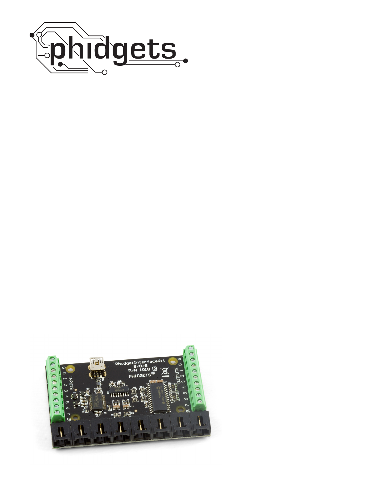
The PhidgetInterfaceKit 8/8/8 allows you to connect devices to any of 8 analog inputs, 8 digital inputs and 8 digital
outputs. It provides a generic, convenient way to interface your PC with various devices.
Analog inputs
Analog Inputs are used to measure continuous quantities, such as temperature, humidity, position, pressure, etc.
Phidgets offers a wide variety of sensors that can be plugged directly into the board using the cable included with
the sensor. Here is a list of sensors currently available:
IRDistanceSensor IRReectiveSensor VibrationSensor LightSensor
Force Sensor Humidity Sensor Temperature Sensor Magnetic Sensor
Rotation Sensor Voltage Divider Touch Sensor Motion Sensor
Mini Joy-Stick Pressure Sensor Voltage Sensor Current Sensor
Slide Sensor
Each analog input can be adjusted to sample at a data rate ranging from 1 sample to up to 1000 samples per
second. Samples are transmitted to your PC every 8ms. This feature is very useful for setting up the resolution of
your data logging. Note that data rate is limited to 16ms when opening over the Phidget Webservice.
Digital Inputs
Digital Inputs can be used to convey the state of push buttons, limit switches, relays, logic levels, etc...
We provide 8 digital input terminals, 1 Ground, and 1 5V.
Digital Outputs
Digital Outputs can be used to drive LEDs, solid state relays (have a look at our SSR board), transistors; in fact,
anything that will accept a CMOS signal.
Digital outputs can be used to control devices that accept a +5V control signal.
We provide 8 digital output terminals, 1 Ground, and 1 5V.
With transistors and some electronics experience, other devices can be controlled, such as buzzers, lights, larger
LEDs, relays.
Programming Environment
Operating Systems: Windows 2000/XP/Vista/7, Windows CE, Linux, and Mac OS X
Programming Languages (APIs): VB6, VB.NET, C#.NET, C++, Flash 9, Flex, Java, LabVIEW, Python, Max/MSP,
and Cocoa.
Examples: Many example applications for all the operating systems and development environments above are
available for download at www.phidgets.com >> Programming.
Connection
The board connects directly to a computer’s USB port.
51018_2_Product_Manual - April 26, 2010
Page 6
Getting Started
Checking the Contents
You should have received:
A PhidgetInterfaceKit 8/8/8 board•
A Mini-USB Cable•
In order to test your new Phidget you will also
need:
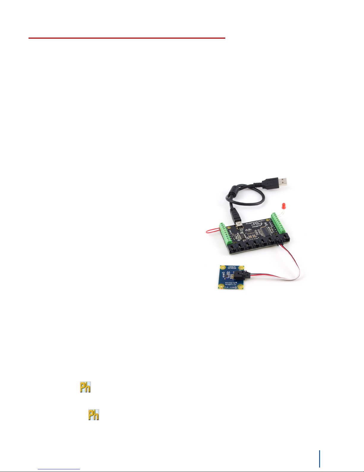
Connecting all the pieces
Connect the Analog Sensor to the analog input port 6 using 1.
a Phidgets sensor cable. The analog ports are numbered
from 0 to 7 starting from the left.
Connect the InterfaceKit board to the PC using the Mini-USB 2.
cable.
Connect one end of the wire to digital input port 0 and the 3.
other end to the ground connection.
A piece of wire to test the digital inputs•
An LED to test the digital outputs•
An Analog Sensor to test the analog inputs. •
Connect the LED by inserting the long LED wire into the 4.
digital output 0 and the shorter wire into Ground.
Testing Using Windows 2000/XP/Vista
Downloading the Phidgets drivers
Make sure that you have the current version of the Phidget library installed on your PC. If you don’t, do the
following:
Go to www.phidgets.com >> Drivers
Download and run Phidget21 Installer (32-bit, or 64-bit, depending on your PC)
You should see the icon on the right hand corner of the Task Bar.
Running Phidgets Sample Program
Double clicking on the icon loads the Phidget Control Panel; we will use this program to make sure that your
new Phidget works properly.
The source code for the InterfaceKit-Full sample program can be found under C# by clicking on www.phidgets.com
>> Programming.
61018_2_Product_Manual - April 26, 2010
Page 7
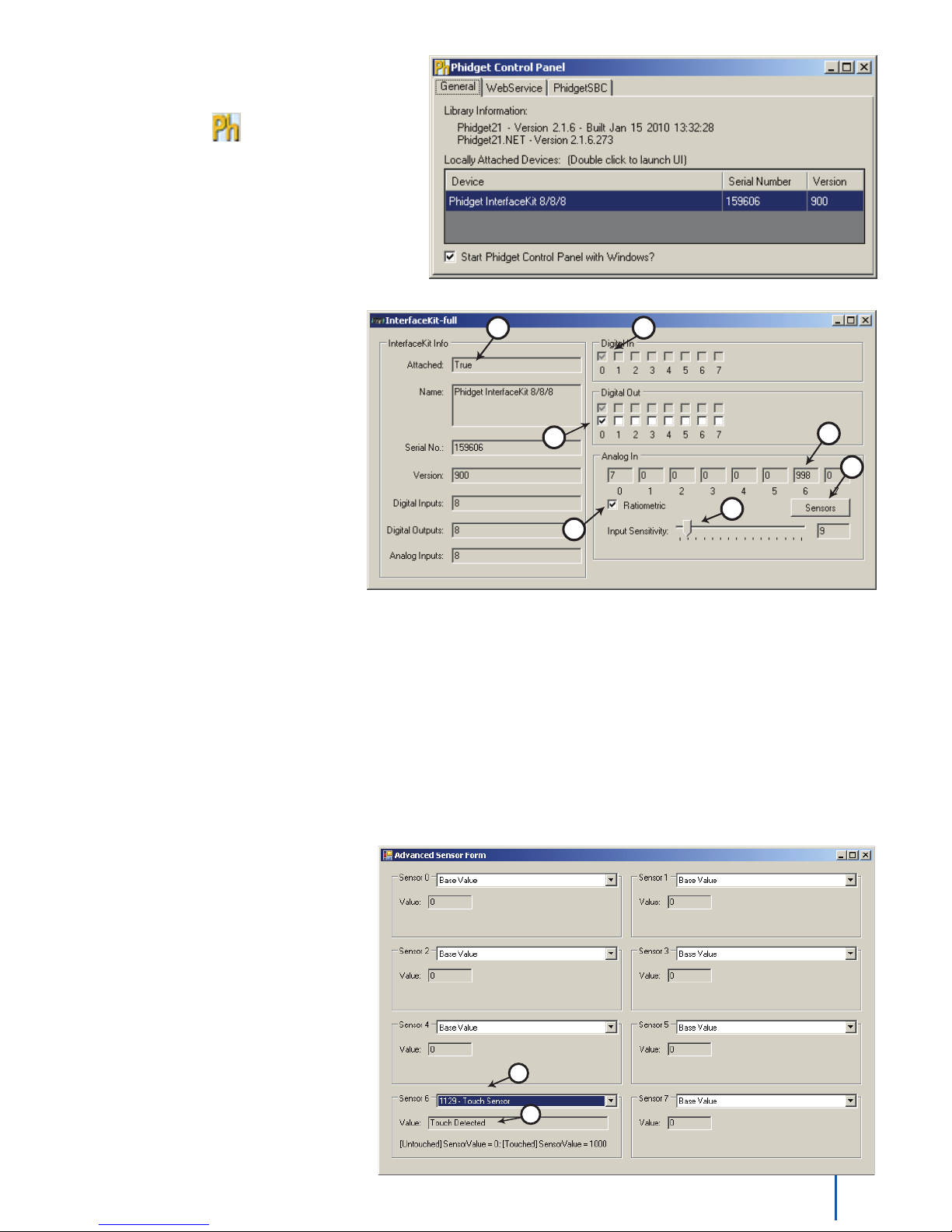
Double Click on the icon to activate the
1
2
6
5
3
4
7
1
2
Phidget Control Panel and make sure that the
Phidget InterfaceKit 8/8/8 is properly
attached to your PC.
Double Click on 1.
PhidgetInterfaceKit 8/8/8 in
the Phidget Control Panel to bring
up InterfaceKit-full and check that
the box labelled Attached contains
the word True.
Test the digital output by clicking 2.
on the white box to turn on the
LED. Clicking again will turn the
LED off. The bottom row shows
the status of the request, while the
top row displays the status of the
digital output as reported by the
device.
Test the digital input by 3.
disconnecting the wire end
connected to the digital input connector. The tick mark in the box will go away.
Click on the Ratiometric Box if your sensor is ratiometric. Check the sensor product manual if you are not sure.4.
Test the Analog Input by activating your sensor and check your results in Analog In number 6.5.
You can adjust the input sensitivity by moving the slider pointer. This is the amount that an input must change 6.
to trigger an event that will modify the value in the Analog In box.
Click on Sensors to launch the Advanced Sensor Form.7.
In the drop down menu, select the 1.
Sensor you have attached to the
analog input port 0 of the 1018. In
our case we select the 1129 - Touch
Sensor.
The state of the Touch Sensor is 2.
shown here.
Note: If you have connected a sensor
that uses a formula, the calculated value
and the formula are displayed under the
drop down menu.
71018_2_Product_Manual - April 26, 2010
Page 8

Testing Using Mac OS X
Click on System Preferences >> Phidgets (under Other) to activate the Preference Pane•
Make sure that the Phidget InterfaceKit 8/8/8 is properly attached.•
Double Click on Phidget InterfaceKit 8/8/8 in the Phidget Preference Pane to bring up the InterfaceKit-Full •
example. This example will function in a similar way as the Windows version, but note that it does not include an
Advanced Sensor Display.
If you are using Linux
There are no sample programs written for Linux.
Go to www.phidgets.com >> Drivers
Download Linux Source
Havealookatthereadmele•
Build Phidget21 •
The most popular programming languages in Linux are C/C++ and Java.
Notes:
Many Linux systems are now built with unsupported third party drivers. It may be necessary to uninstall these
drivers for our libraries to work properly.
Phidget21 for Linux is a user-space library. Applications typically have to be run as root, or udev/hotplug must be
conguredtogivepermissionswhenthePhidgetispluggedin.
If you are using Windows Mobile/CE 5.0 or 6.0
Go to www.phidgets.com >> Drivers
Download x86, ARMV4I or MIPSII, depending on the platform you are using. Mini-itx and ICOP systems will be x86,
and most mobile devices, including XScale based systems will run the ARMV4I.
TheCElibrariesaredistributedin.CABformat.WindowsMobile/CEisabletodirectlyinstall.CABles.
The most popular languages are C/C++, .NET Compact Framework (VB.NET and C#). A desktop version of Visual
StudiocanusuallybeconguredtotargetyourWindowsMobilePlatform,whetheryouarecompilingtomachine
code or the .NET Compact Framework.
81018_2_Product_Manual - April 26, 2010
Page 9

Programming a Phidget
Phidgets’ philosophy is that you do not have to be an electrical engineer in order to do projects that use devices
like sensors, motors, motor controllers, and interface boards. All you need to know is how to program. We have
developed a complete set of Application Programming Interfaces (API) that are supported for Windows, Mac OS X,
and Linux. When it comes to languages, we support VB6, VB.NET, C#.NET, C, C++, Flash 9, Flex, Java, LabVIEW,
Python, Max/MSP, and Cocoa.
Architecture
We have designed our libraries to give you the maximum amount of freedom. We do not impose our own
programming model on you.
To achieve this goal we have implemented the libraries as a series of layers with the C API at the core surrounded
by other language wrappers.
Libraries
The lowest level library is the C API. The C API can be programmed against on Windows, CE, OS X and Linux. With
the C API, C/C++, you can write cross-platform code. For systems with minimal resources (small computers), the C
API may be the only choice.
The Java API is built into the C API Library. Java, by default is cross-platform - but your particular platform may not
support it (CE).
The .NET API also relies on the C API. Our default .NET API is for .NET 2.0 Framework, but we also have .NET
libraries for .NET 1.1 and .NET Compact Framework (CE).
The COM API relies on the C API. The COM API is programmed against when coding in VB6, VBScript, Excel (VBA),
Delphi and Labview.
The ActionScript 3.0 Library relies on a communication link with a PhidgetWebService (see below). ActionScript 3.0
is used in Flex and Flash 9.
Programming Hints
Every Phidget has a unique serial number - this allows you to sort out which device is which at runtime. Unlike •
USB devices which model themselves as a COM port, you don’t have to worry about where in the USB bus you
plug your Phidget in. If you have more than one Phidget, even of the same type, their serial numbers enable
you to sort them out at runtime.
EachPhidgetyouhavepluggediniscontrolledfromyourapplicationusinganobject/handlespecictothat•
phidget. This link between the Phidget and the software object is created when you call the .OPEN group of
commands. This association will stay, even if the Phidget is disconnected/reattached, until .CLOSE is called.
The Phidget APIs are designed to be used in an event-driven architecture. While it is possible to poll them, we •
don’t recommend it. Please familiarize yourself with event programming.
Networking Phidgets
The PhidgetWebService is an application written by Phidgets Inc. which acts as a network proxy on a computer. The
PhidgetWebService will allow other computers on the network to communicate with the Phidgets connected to that
computer. ALL of our APIs have the capability to communicate with Phidgets on another computer that has the
PhidgetWebService running.
The PhidgetWebService also makes it possible to communicate with other applications that you wrote and that are
connected to the PhidgetWebService, through the PhidgetDictionary object.
91018_2_Product_Manual - April 26, 2010
Page 10

Documentation
Programming Manual
The Phidget Programming Manual documents the Phidgets software programming model in a language and device
unspecicway,providingageneraloverviewofthePhidgetsAPIasawhole.Youcanndthemanualatwww.
phidgets.com >> Programming.
Getting Started Guides
We have written Getting Started Guides for most of the languages that we support. If the manual exists for the
languageyouwanttouse,thisistherstmanualyouwanttoread.TheGuidescanbefoundatwww.phidgets.com
>> Programming, and are listed under the appropriate language.
API Guides
We maintain API references for COM (Windows), C (Windows/Mac OSX/Linux), Action Script, .Net and Java. These
references document the API calls that are common to all Phidgets. These API References can be found under www.
phidgets.com >> Programmingandarelistedundertheappropriatelanguage.TolookattheAPIcallsforaspecic
Phidget, check its Product Manual.
Code Samples
We have written sample programs to illustrate how the APIs are used.
Due to the large number of languages and devices we support, we cannot provide examples in every language for
every Phidget. Some of the examples are very minimal, and other examples will have a full-featured GUI allowing
all the functionality of the device to be explored. Most developers start by modifying existing examples until they
have an understanding of the architecture.
Go to www.phidgets.com >> Programming to see if there are code samples written for your device. Find the
language you want to use and click on the magnifying glass besides “Code Sample”. You will get a list of all the
devices for which we wrote code samples in that language.
API for the InterfaceKit 8/8/8
WedocumentAPICallsspecictothisproductinthissection.FunctionscommontoallPhidgetsandfunctionsnot
applicable to this device are not covered here. This section is deliberately generic. For calling conventions under a
speciclanguage,refertotheassociatedAPImanual.Forexactvalues,refertothedevicespecications.
Functions
int InputCount() [get] : Constant = 8
Returns the number of digital inputs supported by this PhidgetInterfaceKit.
bool InputState(int InputIndex) [get]
Returns the state of a particular digital input. Digital inputs read True where they are activated and false when
they are in their default state.
int OutputCount() [get] : Constant = 8
Returns the number of digital outputs supported by this PhidgetInterfaceKit.
bool OutputState (int OutputIndex) [get,set]
Sets/returns the state of a digital output. Setting this to true will activate the output, False is the default state.
Reading the OutputState immediately after setting it will not return the value set - it will return the last state
reported by the Phidget.
int SensorCount() [get] : Constant = 8
Returns the number of sensors (Analog Inputs) supported by this PhidgetInterfaceKit. Note that there is no
way of determining is a sensor is attached, and what sensor is attached.
101018_2_Product_Manual - April 26, 2010
Page 11

int SensorValue(int SensorIndex) [get]
Returns the sensed value of a particular Analog Input. SensorValue varies between 0-1000, corresponding to
the 0-5V input range of the Analog Input.
If you are using an Analog Sensor from Phidgets Inc., it’s manual will specify the formula used to convert
SensorValue into the measured property.
int SensorRawValue (int SensorIndex) [get]
Returns the full resolution of the Analog Input. This is a more accurate version of SensorValue. The valid
range is 0-4095. Note however that the analog outputs on the Interface Kit 8/8/8 are only 10-bit values and
this value represents an oversampling to 12-bit.
double SensorChangeTrigger (int SensorIndex) [get,set]
Returns the change trigger for an analog input. This is the amount that an inputs must change between
successive SensorChangeEvents. This is based on the 0-1000 range provided by getSensorValue. This value is
by default set to 10 for most Interface Kits with analog inputs.
int DataRate (int SensorIndex) [get,set]
Gets/sets the data rate for an analog input. This is corresponds to the fastest rate at which SensorChange
eventswillbered.ThedatarateissupersededbySensorChangeTrigger,whichcanbesetto0ifaconstant
data rate is required. Data Rate is in milliseconds and corresponds to the amount of time between events. Data
Rate is bounded by DataRateMax and DataRateMin. The analog inputs cannot all be set to the fastest data
rate at the same time - if this is attempted, an exception will be thrown when the data bandwidth has been
exceeded. For data rates less then the maximum, data is still sampled at the maximum speed, and averaged
between events for the user. Supported data rates are: 1, 2, 4, 8, and every multiple of 8 until DataRateMin.
Setting an unsupported data rate (ie. 3, 9, 17) will result in a thrown exception. Note that data rate is limited
to 16ms when opening over the Phidget Webservice.
int DataRateMax (int SensorIndex) [get]
The maximum data rate that can be set for an analog input, in milliseconds.
int DataRateMin (int SensorIndex) [get]
The minimum data rate that can be set for an analog input, in milliseconds. This is usually 1000.
bool Ratiometric() [get,set]
Sets/returnsthestateofRatiometric.Ratiometric=truecongurestheAnalogInputstomeasurew.r.tVCC
(nominal5V).Ratiometric=falsecongurestheAnalogInputstomeasurew.r.taninternalprecision5V
reference. Ratiometric is not updated from the Phidget. It is recommended to explicitly set Ratiometric when
the Interfacekit is opened. After changing the ratiometric state, wait until the ratiometric property matches
what was set before reading analog data.
Events
OnInputChange(int InputIndex, bool State) [event]
An event that is issued when the state of a digital input changes.
OnOutputChange(int OutputIndex, bool State), [event]
An event that is issued when the state of a digital output changes.
OnSensorChange(int SensorIndex, int SensorValue), [event]
An event that is issued when the returned value from a sensor (Analog Input) varies by more than the
SensorChangeTrigger property.
111018_2_Product_Manual - April 26, 2010
Page 12
2
3
4
20pF
1K
1M
+V
ANAL OG
GROUND
Phidget
Analog
Input x1
Detail of Analog Input
INPUT
5V PW R
1K
SAMPL ING SWIT CH
ANAL OG
GROUND
INPUT
5V PW R
Phidget
Analog
Input
4K
Sensing the value of a variable resistance sensor
FSR
In this cas e, an FSR (force sensitiv e resisto r) is shown.
100nF
Technical Section
Analog Inputs
Using the Analog Inputs with Sensors provided by Phidgets
Analogs Inputs are used to interface many different types of sensors. Each Analog Input provides power (Nominal
+5VDC), ground, and an analog voltage return wire driven by the sensor to some voltage. The PhidgetInterfaceKit
continuously measures this return voltage and reports it to the application.
Analog Inputs are used to measure continuous quantities, such as temperature, humidity, position, pressure, etc.
Phidgets offers a wide variety of sensors that can be plugged directly into the board using the cable included with
the sensor.
Using the Analog Inputs with your own sensors
For users who wish to interface their own sensors, we describe the Analog Inputs here.
Mechanical
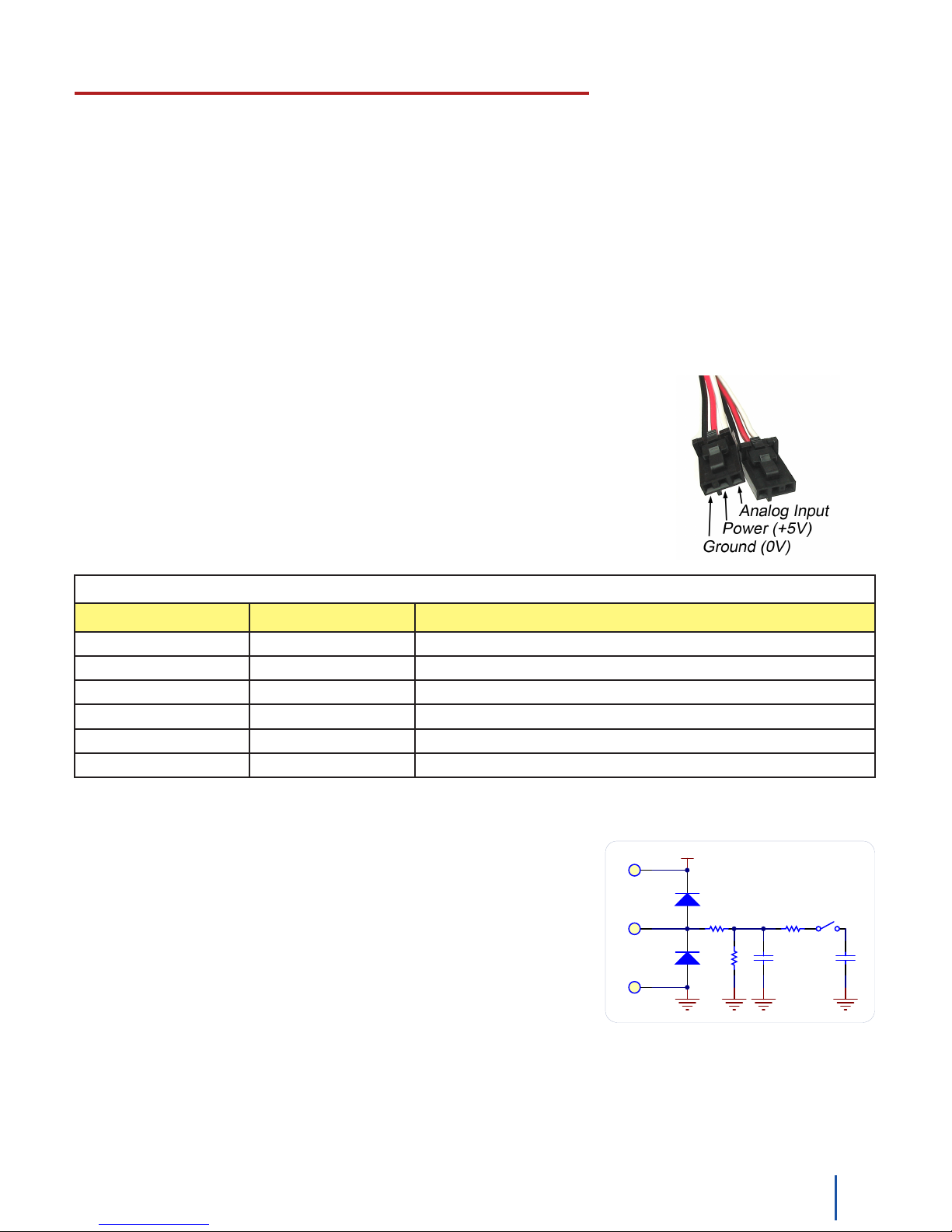
Each Analog Input uses a 3-pin, 0.100 inch pitch locking connector. Pictured here is a
plug with the connections labeled. The connectors are commonly available - refer to
the Table below for manufacturer part numbers.
Cable Connectors
Manufacturer Part Number Description
Molex 50-57-9403 3 Position Cable Connector
Molex 16-02-0102 Wire Crimp Insert for Cable Connector
Molex 70543-0002 3 Position Vertical PCB Connector
Molex 70553-0002 3 Position Right-Angle PCB Connector (Gold)
Molex 70553-0037 3 Position Right-Angle PCB Connector (Tin)
Molex 15-91-2035 3 Position Right-Angle PCB Connector - Surface Mount
Note: Most of the above components can be bought at www.digikey.com
Electrical
The maximum total current consumed by all Analog Inputs should be
limited to 400mA.
The analog measurement is represented in the software through the
SensorValue as a value between 0 and 1000. A sensor value of 1 unit
represents a voltage of approximately 5 millivolts. The RawSensorValue
property brings out a 12-bit value (0-4095) for users who require
maximum accuracy. Please note that the sampling is actually done with
an oversampled 10-bit ADC, but reported as a 12-bit value to allow future
expansion.
Ratiometric Conguration
The group of Analog Inputs can be collectively set to Ratiometric mode from software using the Ratiometric
property. If you are using a sensor whose output changes linearly with variations in the sensor’s supply voltage
level,itissaidtoberatiometric.MostofthesensorssoldbyPhidgetsareratiometric(thisisspeciedontheweb
product page and in the sensor’s product manual).
121018_2_Product_Manual - April 26, 2010
Page 13
Setting Ratiometric causes the reference to the internal Analog to Digital Converter to be set to the power supply
3
4
ANALOG
GROUND
INPUT
5V PW R
Phidget
Analog
Input
4K
Sensing the value of a variable resistance sensor
FSR
voltage level. When Ratiometric is enabled, the maximum voltage returned on the Analog Input should be the +5V
nominal power provided by the PhidgetInterfaceKit.
Non-Ratiometric Conguration
If Ratiometric is false, the ADC reference is set to a 5.0V 0.5% stable voltage reference. The maximum voltage
returned on the Analog Input should be maximum 5.0V. Note that the Analog Input power supply voltage is not
affected by the setting of the Ratiometric property.
Factors that can affect Accuracy
High Output Impedance - Sensors that have a high output impedance will be distorted by the 900K input
impedance of the Analog Input. If your output impedance is high, it is possible to correct for this distortion to some
extent in your software application.
Power Consumption - Sensor cables have some resistance, and the power consumption of the sensor will cause
the sensor to have a slightly different ground from the Analog Input on the PhidgetInterfaceKit. The more power
consumed by the sensor, and the longer the sensor cable, the more pronounced this effect will be.
Intrinsic Error In Sensors - For many sensors, the error is quite predictable over the life of the sensor, and it can
be measured and calibrated out in software.
Non-Ratiometric Conguration - Voltage Reference error. The 5.0VDC voltage reference is accurate to 0.5%.
Thiscanbeasignicantsourceoferrorinsomeapplications,butcanbeeasilymeasuredandcompensatedfor.
Changing the Data Rate
You can change the data rate for each Analog Input from 1 millisecond to 1 second. By default, the analog input
data set is sent to the PC every 8ms. If, for example, you set the data rate to 1ms, you will receive a packet
containing 8 miliseconds worth of 1 ms samples every 8ms. For values less than 8 ms, the data rate sets the
sampling rate, not the transmission rate. When the Data rate is set at a multiple of 8 ms, the data rate sets both the
sampling rate and the transmission rate.
There is also a limit as to how many channels can be set at a high sampling rate, since you will, at one point run out
of bandwidth. We estimate that you can set up to 4 channels to 1ms or you could set all channels to 2ms. You will
get an error when you exceed the available bandwidth, warning you of lost data samples.
Setting the data rate at 1, 2, or 4ms will not allow you to react to received sensor data any faster than every
8ms. You will simply get more sample data. This feature is useful if you need to log sensor data at less than 8 ms
resolution.
Note that data rate is limited to at most 16ms when opening over the Phidget Webservice. Actual data rate will
depend on network latency.
Connecting non-Phidget devices to the Analog Inputs
Here are some circuit diagrams that illustrate how to connect various non Phidgets devices to the analog inputs on
your Phidget.
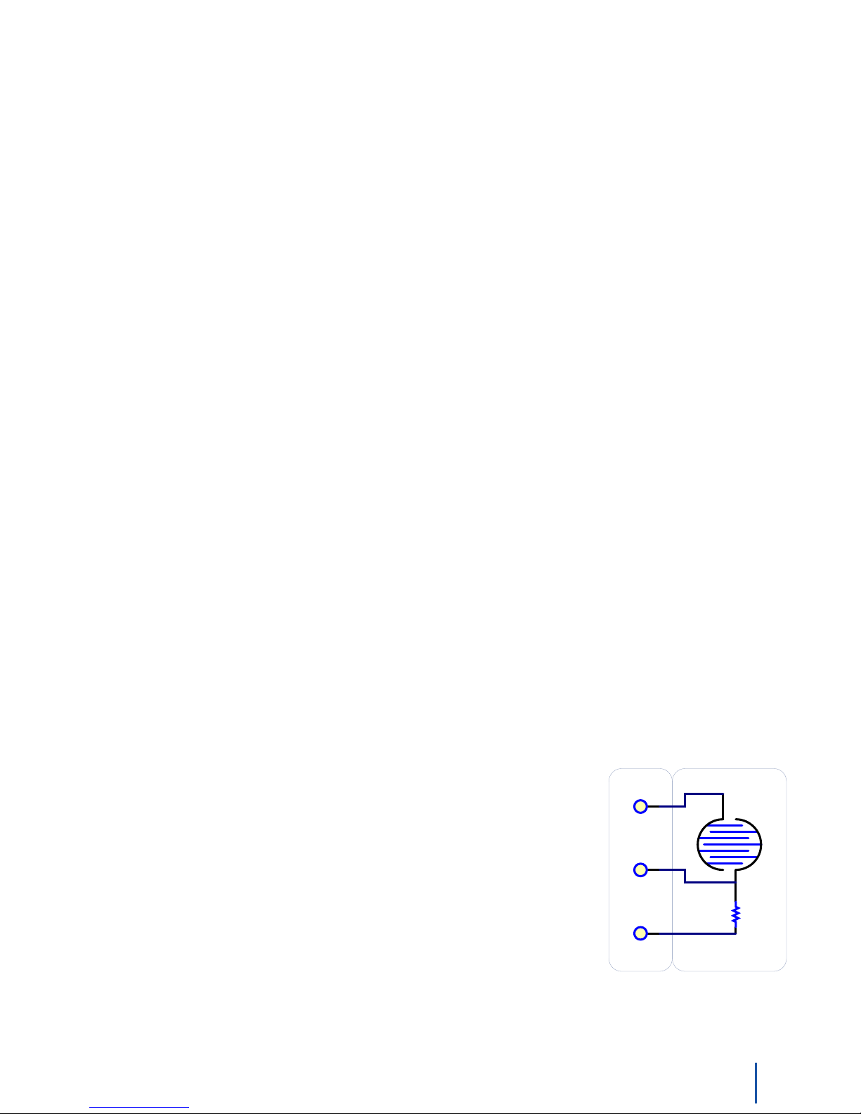
Sensing the value of a variable resistance sensor
In this diagram, an FSR (Force Sensitive Resistor) is shown.
131018_2_Product_Manual - April 26, 2010
Page 14
Sensing the position of a potentiometer
3
4
4K
FSR
ANALOG
GROUND
INPUT
5V PW R
Phidget
Analog
Input
Interfacing to an arbitrary sensor
GND
3
VOUT
2
VCC
1
100nF
1K
100nF
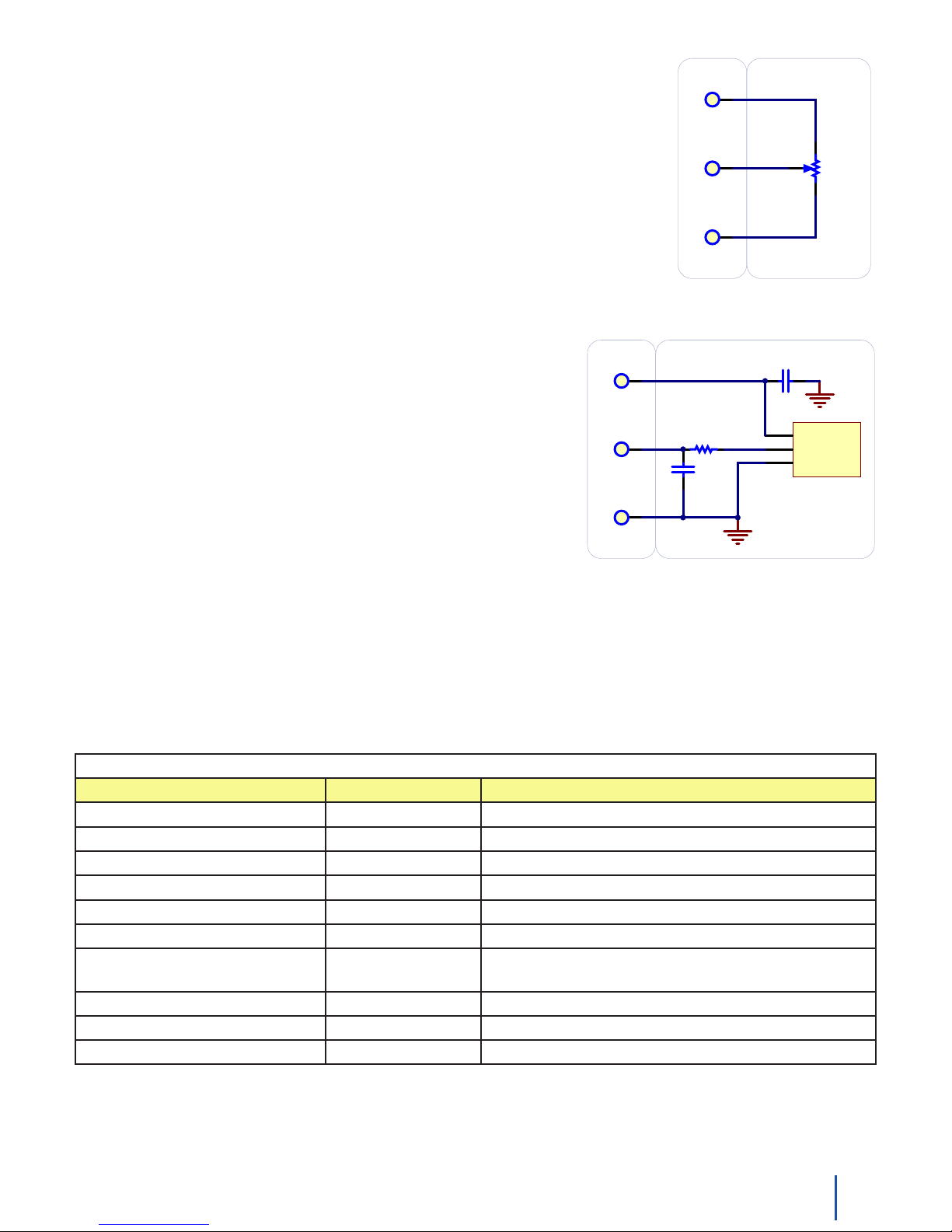
Note the use of power supply decoupling and the RC Filter on the output.
The RC f ilter also prevents VOUT from oscillating on many sensors.
2
3
4
20pF
1K
SAMPL I NG SWI TCH
ANALOG
GROUND
INPUT
5V PW R
Phidget
Analog
Input
4K
Sensing the value of a variable resistance sensor
FSR
In this case, an FSR (force sensitive resistor) is shown.
1K
ANALOG
GROUND
INPUT
5V PW R
Phidget
Analog
Input
Sensing the position of a potentiometer
ANALOG
GROUND
INPUT
5V PW R
Phidget
Analog
Input
Interfacing to an arbitrary sensor
GND
3
VOUT
2
VCC
1
100nF
1K
100nF
Note the use of power supply decoupling and the RC Filter on the output.
The RC f ilter also prevents VOUT from oscillating on many sensors.
Interfacing to an arbitrary sensor
Note the use of power supply decoupling and the RC Filter on the
output.TheRClteralsopreventsVOUTfromoscillatingonmany
sensors
Non Phidgets Sensors
In addition to Phidgets sensors, any sensor that returns a signal between 0 and 5 volts can be easily interfaced.
Here is a list of interesting sensors that can be used with the PhidgetInterfaceKit 8/8/8. Note: these sensors are not
“plug & play” like the sensors manufactured by Phidgets.
Manufacturer Part Number Description
MSI Sensors FC21/FC22 Load cells - measure up to 100lbs of force
Humirel HTM2500VB Humidity sensors
Measurement Specialties MSP-300 Pressure sensors - ranges up to 10,000 PSI
Freescale Semiconductor MPXA/MPXH Gas Pressure Sensors
Allegro ACS7 series Current Sensors - ranges up to 200 Amps
Allegro A1300 series LinearHallEffectSensors-todetectmagneticelds
Analog TMP35 TMP36
Panasonic AMN series Motion Sensors
Honeywell FS01, FS03 Small, accurate Piezo-resistive load cells
AllSensors-Europe BARO-A-4V Barometric Pressure Sensor - 600 to 1,100 mbar
TMP37
Analog Sensors
Temperature Sensor
Note: Most of the above components can be bought at www.digikey.com
141018_2_Product_Manual - April 26, 2010
Page 15
Digital Inputs
100nF
15K
15K
+5V +5V
INPUT
GROUND
INPUT
GROUND
USER
SW IT CH
W iring a switch to a Digital Input
Phidget
Digital
Input x1
APPLICATION
Phidget
Digital
Input
Phidget
Digital
Input
100nF
15K
15K
+5V +5V
INPUT
GROUND
Phidget
Digital
Input x1
Monitoring the position of a Relay
K 1
USER
APPLICATION
Relay contact causes Digital Input to report TRUE
INPUT
GROUND
Phidget
Digital
Input
Digital Input Hardware Filter
Thereisbuilt-inlteringonthedigitalinput,toeliminatefalsetriggeringfromelectricalnoise.Thedigitalinputis
rstRClteredbya15K/100nFnode,whichwillrejectnoiseofhigherfrequencythan1Khz.Thisltergenerally
eliminates the need to shield the digital input from inductive and capacitive coupling likely to occur in wiring
harnesses.
Digital Input Hysteresis
The digital input has hysteresis - that is, it will hold it’s current state (false or true), unless a large change occurs.
To guarantee FALSE, the digital input must be at least 3.75V, and to guarantee TRUE, the digital input must be less
than 1.25V.
Digital Input Sampling Characteristics
The state of the digital inputs are reported back to the PC periodically. During this sampling period, if a digital input
was true for greater than 4.0ms, the digital input is guaranteed to be reported as true in software. This makes
the digital input much more sensitive to reporting TRUE state, and makes it useful to watch for short events. Any
Digital Input True events of less than 1.5ms are never reported.
5Volt Terminal Block
For users who need it, we provide 5V on the terminal block next to Digital Input 7.
Functional Block Diagram
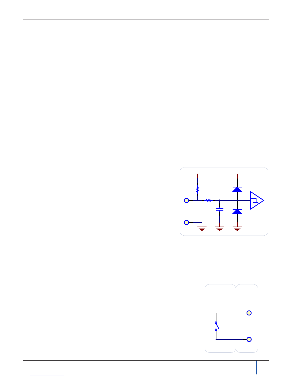
The digital inputs have a built in 15K pull-up resistor. By connecting
external circuitry, and forcing the input to Ground, the Digital Input
in software will read as TRUE. The default state is FALSE - when you
have nothing connected, or your circuitry (switch, etc) is not pulling the
input to ground.
Using the Digital Inputs
Here are some circuit diagrams that illustrate how to connect various devices to the digital inputs on your Phidget.
Wiring a switch to a Digital Input
Closing the switch causes the digital input to report TRUE.
151018_2_Product_Manual - April 26, 2010
Page 16
Monitoring the position of a Relay
K 1
Isolating a Digital Input with an Optocoupler
USER
APPLICATION
Relay contact causes Digital Input to report TRUE
Current through LED causes Digital Input to report TRUE
Drain-Source Current > 270uA causes Digital Input to report TRUE
Drain-Source Current < 67uA guarantees Digital Input to report TRUE
USER
APPLICATION
1K
R1
VS1
U1
OptoCoupler
INPUT
GROUND
Phidget
Digital
Input
INPUT
GROUND
Phidget
Digital
Input
100nF
15K
15K
+5V +5V
INPUT
GROUND
INPUT
GROUND
USER
SW I T CH
W iring a switch to a Digital Input
Phidget
Digital
Input x1
APPLICATION
Phidget
Digital
Input
Detecting an external Voltage with an N-Channel MOSFET
1K
R1
USER
APPLICATION
VS1
Q1
INPUT
GROUND
Phidget
Digital
Input
Phidget
Digital
Input
Phidget
Digital
Input
Monitoring the position of a Relay
K 1
USER
APPLICATION
INPUT
GROUND
Phidget
Digital
Input
Monitoring the position of a Relay
K 1
FSR
Isolating a Digital Input with an Optocoupler
USER
APPLICATION
Relay contact causes Digital Input to report TRUE
Current through LED causes Digital Input to report TRUE
USER
Using an FSR as a switch
APPLICATION
FSR Resistance f alling below 3.75k Ohms causes Digital Input to go TRUE
FSR Resistance rising above 75k Ohms causes Digital Input to go FALSE
This design can be used with any variable resistance sensor - CDS Photocells.
Q1
Drain-Source Current > 270uA causes Digital Input to report TRUE
Drain-Source Current < 67uA guarantees Digital Input to report TRUE
USER
APPLICATION
USER
APPLICATION
10K
R1
VS1
1K
R1
VS1
U1
OptoCoupler
INPUT
GROUND
Phidget
Digital
Input
INPUT
GROUND
Phidget
Digital
Input
INPUT
GROUND
Phidget
Digital
Input
INPUT
GROUND
Phidget
Digital
Input
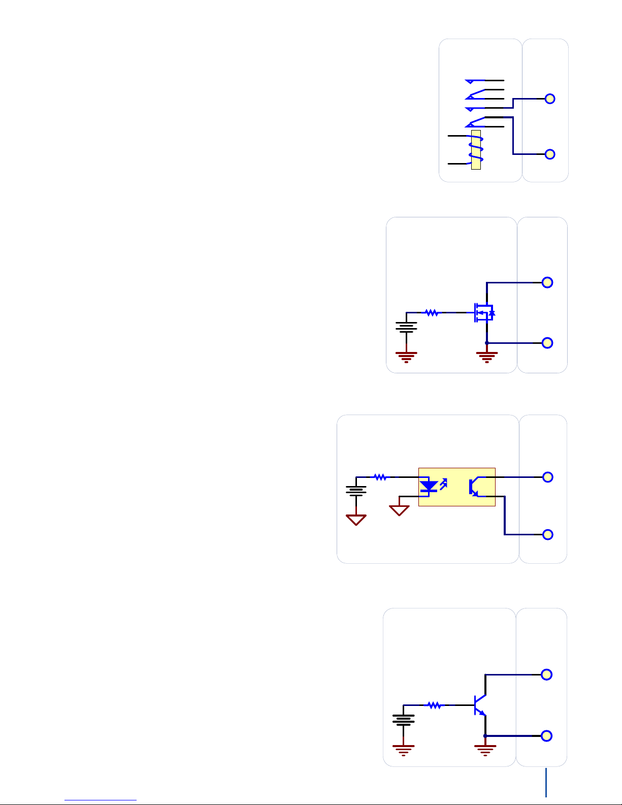
Monitoring the position of a relay
The relay contact can be treated as a switch, and wired up similarly. When the
relay contact is closed, the Digital Input will report TRUE.
Detecting an external Voltage with an N-Channel MOSFET
A MOSFET can be used to detect the presence of an external voltage.
The external voltage will turn on the MOSFET, causing it to short the
Digital Input to Ground.
If the MOSFET is conducting > 270uA, the Digital Input is guaranteed
to report TRUE.
If the MOSFET is conducting < 67uA, the Digital Input is guaranteed to
report FALSE.
The voltage level required to turn on the MOSFET depends on the make
of of MOSFET you are using. Typical values are 2V-6V.
Isolating a Digital Input with an Optocoupler
When driving current through the LED, the Digital Input will
report TRUE. The amount of current required will depend on
the optocoupler used. Design to sink at least 270uA to cause
the digital input to report TRUE, and less than 67uA to report
FALSE.
Detecting an external Voltage with an NPN Transistor
This circuit can be used to measure if a battery is connected, or if 12V
(for example) is on a wire.
By designing to have Collector-Emitter current > 270uA, the digital
input will report TRUE.
161018_2_Product_Manual - April 26, 2010
Page 17
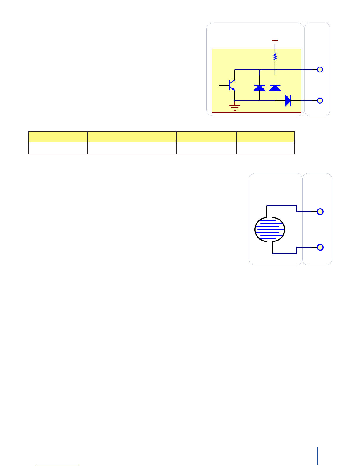
Monitoring the position of a Relay
K 1
FSR
Isolating a Digital Input with an Optocoupler
USER
USER
Using an FSR as a switch
APPLICATION
USER
APPLICATION
1K
R1
U1
OptoCoupler
INPUT
GROUND
Phidget
Digital
Input
INPUT
GROUND
Phidget
Digital
Input
INPUT
GROUND
Phidget
Digital
Input
Monitoring the position of a Relay
K 1
Isolating a Digital Input with an Optocoupler
USER
APPLICATION
Relay contact causes Digital Input to report TRUE
Current through LED causes Digital Input to report TRUE
Drain-Source Current > 270uA causes Digital Input to report TRUE
Drain-Source Current < 67uA guarantees Digital Input to report TRUE
USER
APPLICATION
1K
R1
VS1
U1
OptoCoupler
INPUT
GROUND
Phidget
Digital
Input
INPUT
GROUND
Phidget
Digital
Input
USER
APPLICATION
INPUT
GROUND
Phidget
Digital
Input
Q1
+10-30V
Connecting a 3-wire Capacitive or Inductive Proximity Switch
Proximity Switch
Using a Capacitive or Inductive Proximity Switch
Capacitive proximity switches can detect the presence of nearby
non-metallic objects, whereas inductive proximity switches
can detect only the presence of metallic objects. To properly
interface one of these proximity switches to the digital inputs, a
3-wire proximity switch is required, as well as an external power
supply.
We have checked the following switch from Automation Direct
to verify that it works with the Digital Inputs. Similar capacitive
or inductive proximity switches from other manufacturers should
work just as well.
Manufacturer Web Page Capacitive Part No Inductive Part No
Automation Direct www.automationdirect.com CT1 Series AM1 Series
Using an FSR or other variable resistor as a switch
The digital inputs can be easily wired to use many variable resistors as switches.
If the resistance falls below 3.75k Ohms, the Digital Input will go TRUE.
If the resistance rises above 75k Ohms, the Digital Input will go FALSE.
171018_2_Product_Manual - April 26, 2010
Page 18
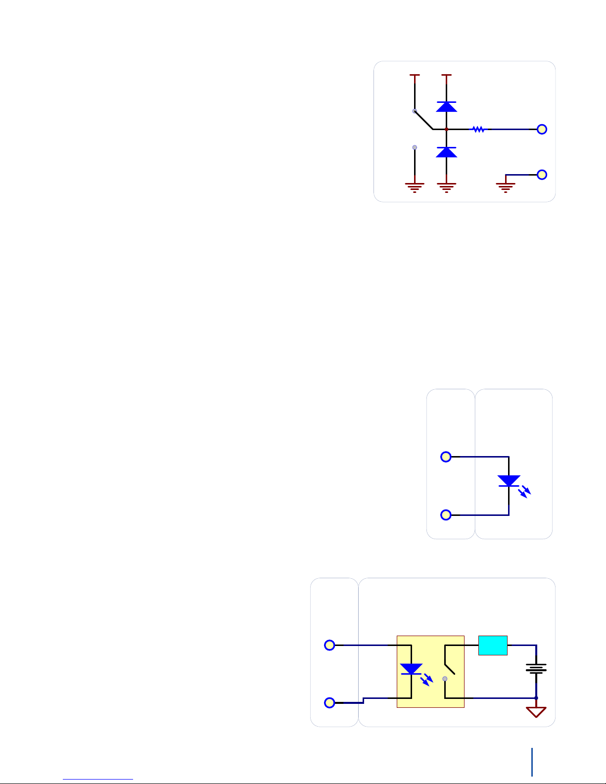
Digital Outputs
Q1
250
+5V
Detail of Digital Output
TRUE
FALSE
+5V
OUTPUT
GROUND
Isolating a Digital Output with a Optocoupler
Driving LED causes output transistor to sink current
Maximum current through transistor will depend in part on the transfer characteristics of the optocoupler
Be conservative, and ref er to the datasheet of the optocoupler
K 1
D1
Controlling a relay with a NPN Transistor.
K 1
D1
Can often be used to control AC or DC
USER
APPLICATION
USER
APPLICATION
USER
APPLICATION
USER
APPLICATION
USER
APPLICATION
Phidget Digital
Output x1
VS1
VS1VS3
Q1
VS1
L oad
U1
OptoCoupler
L oad
D1
Using a 3052 SSR Board w ith a Digital Output
Driving Output causes output of 3052 to Turn on
Can be used to control AC or DC
USER
APPLICATION
The Load can also be switched with the 3052 on the high side.
3052
RED
BLACK
OUTPUT
GROUND
Phidget
Digital
Output
OUTPUT
GROUND
Phidget
Digital
Output
OUTPUT
GROUND
Phidget
Digital
Output
OUTPUT
GROUND
Phidget
Digital
Output
Phidget
Digital
Output
K 1
VS1
Using a 3052 SSR Board w ith a Digital Output
Driving Output causes output of 3052 to Turn on
Can be used to control AC or DC
USER
APPLICATION
VS1
L oad
The Load can also be switched with the 3052 on the high side.
3052
RED
BLACK
Using a 3051 Dual Relay Board with one or two Digital Outputs
Driving Outputs causes 3051 Relay s to Turn on
Can be used to control AC or DC
USER
APPLICATION
Analog Input is for powering Relay s Only
0C
0NO
0NC
1C
1NO
1NC
CTL 0
CTL 1
ANL GI N
3051
OUTPUT
GROUND
Phidget
Digital
Output
OUTPUT
Phidget
Digital
Output
OUTPUT
ANALOG
INPUT
Q1
250
+5V
Detail of Digital Output
TRUE
FALSE
+5V
OUTPUT
GROUND
Isolating a Digital Output with a Optocoupler
Driving LED causes output transistor to sink current
Maximum current through transistor will depend in part on the transfer characteristics of the optocoupler
Be conservative, and ref er to the datasheet of the optocoupler
K 1
D1
Controlling a relay with a NPN Transistor.
USER
APPLICATION
USER
APPLICATION
Phidget Digital
Output x1
VS1
VS1VS3
L oad
U1
OptoCoupler
Using a 3052 SSR Board with a Digital Output
Driving Output causes output of 3052 to Turn on
Can be used to control AC or DC
USER
APPLICATION
VS1
L oad
The Load can also be switched with the 3052 on the high side.
3052
RED
BLACK
Using a 3051 Dual Relay Board with one or two Digital Outputs
Driving Outputs causes 3051 Relay s to Turn on
Can be used to control AC or DC
USER
APPLICATION
Analog Input is for powering Relay s Only
CTL 0
CTL 1
ANL GI N
3051
OUTPUT
GROUND
Phidget
Digital
Output
OUTPUT
GROUND
Phidget
Digital
Output
OUTPUT
GROUND
Phidget
Digital
Output
OUTPUT
Phidget
Digital
Output
OUTPUT
ANALOG
INPUT
Functional Block Diagram
The 250 ohm resistance is internal to the PhidgetInterfaceKit 8/8/8,
andlimitsthecurrentthatcanowthroughtheoutput.Thisis
intended to protect the device from being damaged if there is a short
to ground or if an LED is used. The output is intended to drive TTL or
CMOS inputs; it is not designed to provide power to an external circuit.
Ground Protection
Ground terminals on the InterfaceKit share a common ground with USB ground. Because they are not internally
isolated, these terminals will expose the USB ground potential of the PC to which they are connected. Be sure you
are completely familiar with any circuit you intend to connect to the InterfaceKit before it is connected. If a reverse
voltage or dangerously high voltage is applied to the input or output terminals, damage to the Phidget or the PC
may result.
5Volt Terminal Block
For users who need it, we provide 5V on the terminal block next to Digital Output 7.
Using the Digital Outputs
Here are some circuit diagrams that illustrate how to connect various devices to the digital outputs on your Phidget.
Driving an LED with the Digital Output
Connecting an LED to a digital output is simple. Wire the anode to a digital output
labeled 0 to 7 on the Interface Kit, and the cathode to a supplied ground, labeled
G.
Using a 3052 SSR Board with a Digital Ouptut
Setting the digital output to true causes the output of the
3052 to turn on. This can be used to control AC or DC
devices. The load can also be switched with the 3052 on
the high side. High side switching is helpful for powering
more complicated circuitry that cannot tolerate having
multiple grounds.
181018_2_Product_Manual - April 26, 2010
Page 19
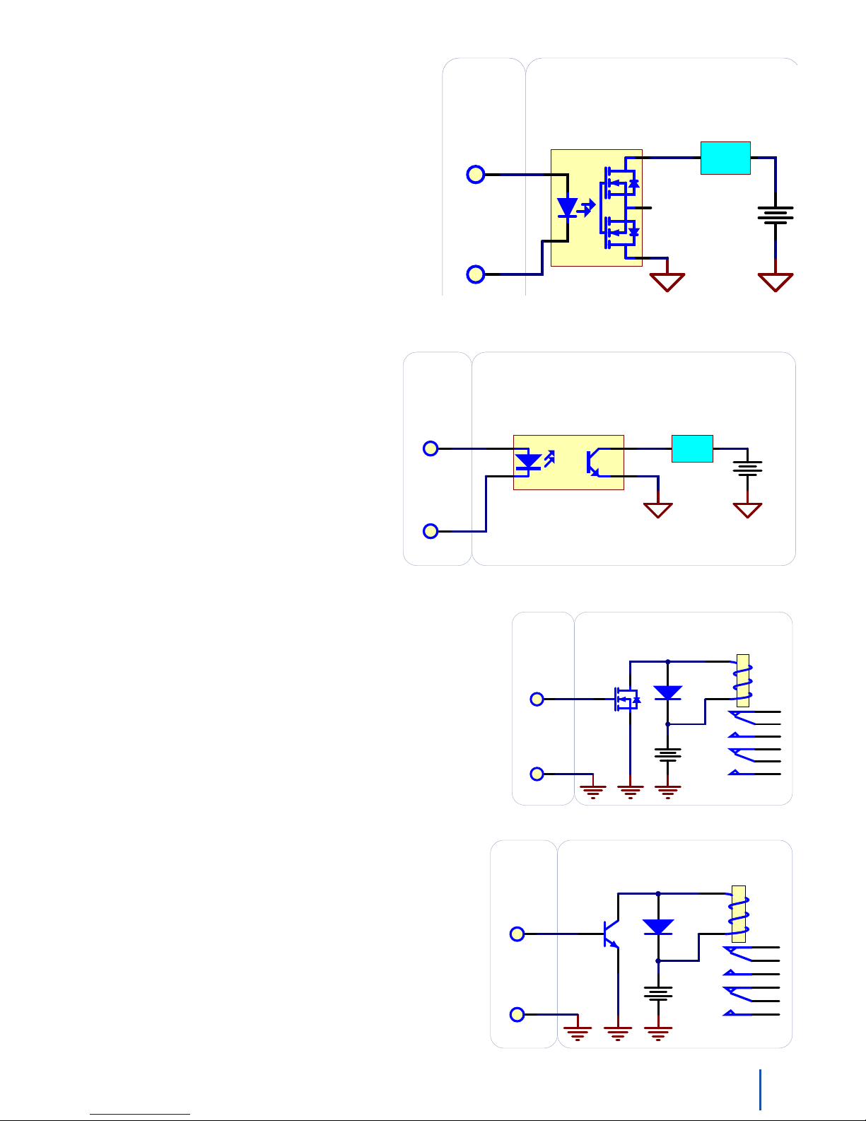
Q1
K 1
D1
Controlling a relay with a NPN Transistor.
K 1
OUTPUT
GROUND
Phidget
Digital
Output
D1
Controlling a relay with a N-Channel MOSFET
Be sure to use a Logic-Level Mosf et - so the +5V
Digital Output is able to turn it on.
USER
APPLICATION
USER
APPLICATION
VS1
VS3
Q1
OUTPUT
GROUND
Phidget
Digital
Output
Phidget
Digital
Output
Q1
Isolating a Digital Output with a Optocoupler
Driving LED causes output transistor to sink current
Be conservative, and ref er to the datasheet of the optocoupler
K 1
D1
Controlling a relay with a NPN Transistor.
USER
APPLICATION
USER
APPLICATION
VS1
VS1VS3
L oad
U1
OptoCoupler
Using a 3051 Dual Relay Board with one or two Digital Outputs
Driving Outputs causes 3051 Relay s to Turn on
Can be used to control AC or DC
USER
APPLICATION
Analog Input is for powering Relay s Only
0C
0NO
0NC
1C
1NO
1NC
CTL 0
CTL 1
ANL GI N
3051
OUTPUT
GROUND
Phidget
Digital
Output
OUTPUT
GROUND
Phidget
Digital
Output
OUTPUT
Phidget
Digital
Output
OUTPUT
ANALOG
INPUT
Q1
K 1
D1
Controlling a relay with a NPN Transistor.
USER
APPLICATION
VS1VS3
Using a 3051 Dual Relay Board with one or two Digital Outputs
Driving Outputs causes 3051 Relay s to Turn on
Can be used to control AC or DC
USER
APPLICATION
Analog Input is for powering Relay s Only
0C
0NO
0NC
1C
1NO
1NC
CTL 0
CTL 1
ANL GI N
OUTPUT
GROUND
Phidget
Digital
Output
OUTPUT
Phidget
Digital
Output
OUTPUT
ANALOG
Q1
Isolating a Digital Output with a Optocoupler
Driving LED causes output transistor to sink current
Maximum current through transistor will depend in part on the transfer characteristics of the optocoupler
Be conservative, and refer to the datasheet of the optocoupler
K 1
D1
Controlling a relay with a NPN Transistor.
K 1
OUTPUT
GROUND
Phidget
Digital
Output
D1
Controlling a relay with a N-Channel MOSFET
Be sure to use a Logic-Level Mosfet - so the +5V
Digital Output is able to turn it on.
Isolating a the Digital Output with a MOSFET-Based SSR
Driving LED causes output transistors to turn on
Can often be used to control AC or DC
USER
APPLICATION
USER
APPLICATION
USER
APPLICATION
USER
APPLICATION
VS1
VS1VS3
Q1
VS1
L oad
U1
OptoCoupler
L oad
The Load can also be switched with the SSR on the high side.
OUTPUT
GROUND
Phidget
Digital
Output
OUTPUT
GROUND
Phidget
Digital
Output
OUTPUT
GROUND
Phidget
Digital
Output
Phidget
Digital
Output
Isolating a Digital Output with a MOSFET based
SSR
It’s possible to wire up your own Solid State Relay to the
digital output. MOSFET based SSRs have the advantage
that they can be understood as being a simple switch.
There are many other types of SSRs that are more
suitable for controlling higher power, higher voltage AC
devices that can also be controlled in the same fashion.
Isolating a Digital Output with an
Optocoupler
In some applications, particularly where there is
a lot of electrical noise (automotive), or where
you want maximum protection of the circuitry
(interactive installations, kiosks), electrical
isolation buys you a huge margin of protection.
Driving the LED causes the output transistor to
sink current. The maximum current through
the transistor will depend in part on the
characteristics of the optocoupler.
Controlling a relay with a N-Channel MOSFET
Ainexpensivemosfetandybackdiodecanbeusedtocontrol
larger loads - relays for example - directly from the digital output.
Be sure to use a Logic-Level MOSFET so that the +5V Digital
Output is able to turn it on.
Controlling a relay with a NPN transistor
This circuit is very similar to the N-channel mosfet - but you
may already have NPN transistors on hand.
191018_2_Product_Manual - April 26, 2010
Page 20
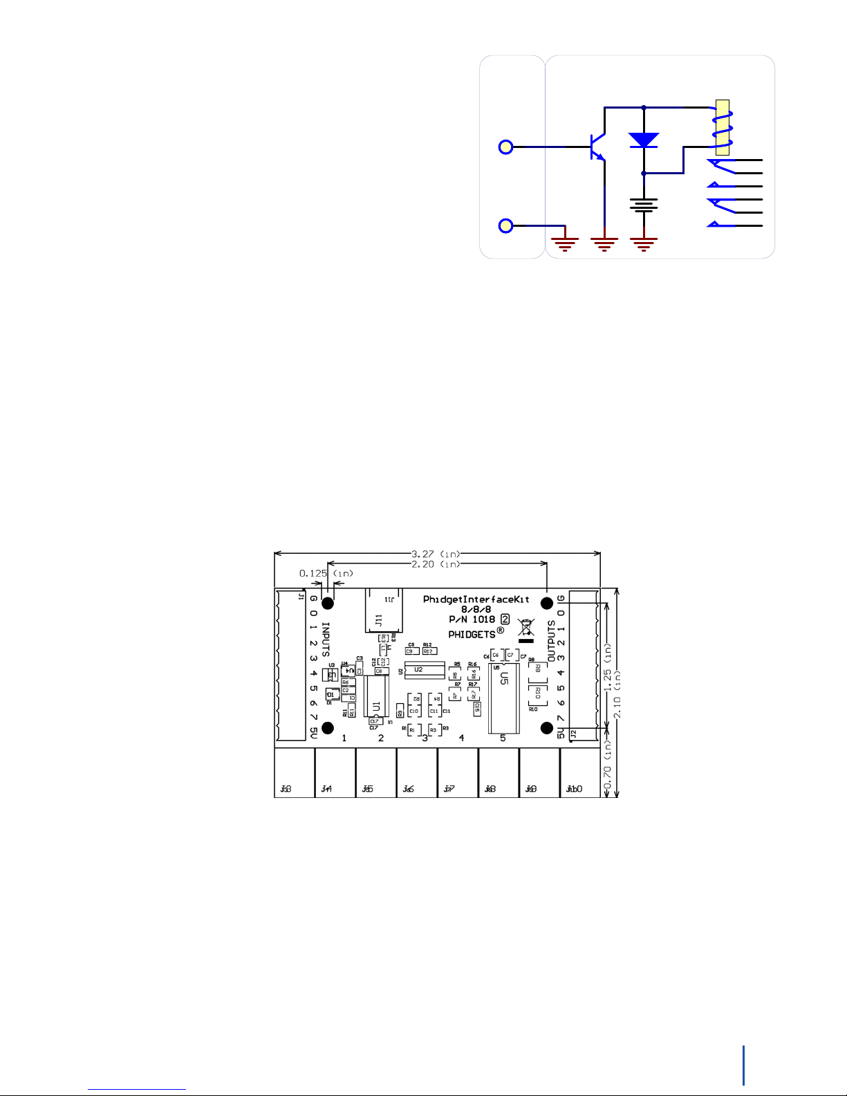
Using a 3051 Dual Relay Board with one or two Digital
Q1
K 1
D1
Controlling a relay with a NPN Transistor.
USER
APPLICATION
VS1VS3
Using a 3051 Dual Relay Board with one or two Digital Outputs
Driving Outputs causes 3051 Relay s to Turn on
Can be used to control AC or DC
USER
APPLICATION
Analog Input is for powering Relay s Only
0C
0NO
0NC
1C
1NO
1NC
CTL 0
CTL 1
ANL GI N
OUTPUT
GROUND
Phidget
Digital
Output
OUTPUT
Phidget
Digital
Output
OUTPUT
ANALOG
Outputs
The 3051 Dual Relay Board is designed to be used with the
PhidgetInterfaceKit 8/8/8. An Analog Input can be used to supply
power to the relays, and one or two digital outputs used to control
the relays. The 3051 is a good option if you need a couple relays
in your project.
Mechanical Drawing
1:1 scale
Note: When printing the mechanical drawing, “Page Scaling” in the Print panel must be set to “None” to avoid
re-sizing the image.
201018_2_Product_Manual - April 26, 2010
Page 21
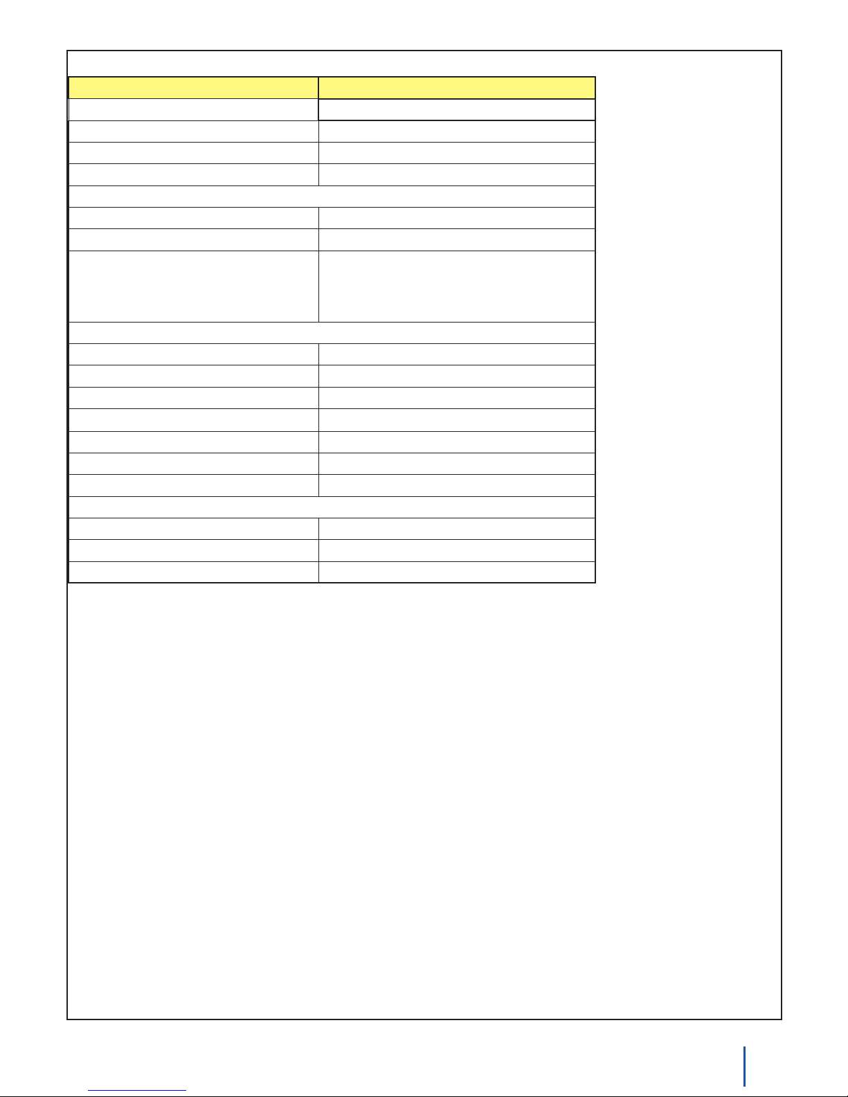
Device Specications
Characteristic Value
USB Voltage 4.75 to 5.25 V
USB-PowerCurrentSpecication Max 500 mA
Quiescent Current Consumption 13 mA
Available External Current (source) 487 mA
Analog Inputs
Impedance 900K ohms
5V Reference Error Max 0.5%
Update Rate 1000 samples/second max for 4 channels
500 samples/second max for all 8 channels
62.5 samples/second max over webservice
Digital Inputs
Pull-Up Resistance 15K ohms
Low Voltage (True) 1.25V Max
High Voltage (False) 3.75V Min
Maximum Voltage
Update Rate ~125 samples/second
Recommended Wire Size 16 - 26 AWG
Wire Stripping 5-6mm strip
Digital Outputs
Series Resistance 300 ohms
Update Rate ~125 samples/second
Recommended Wire Size 16 - 26 AWG
±15V
211018_2_Product_Manual - April 26, 2010
Page 22
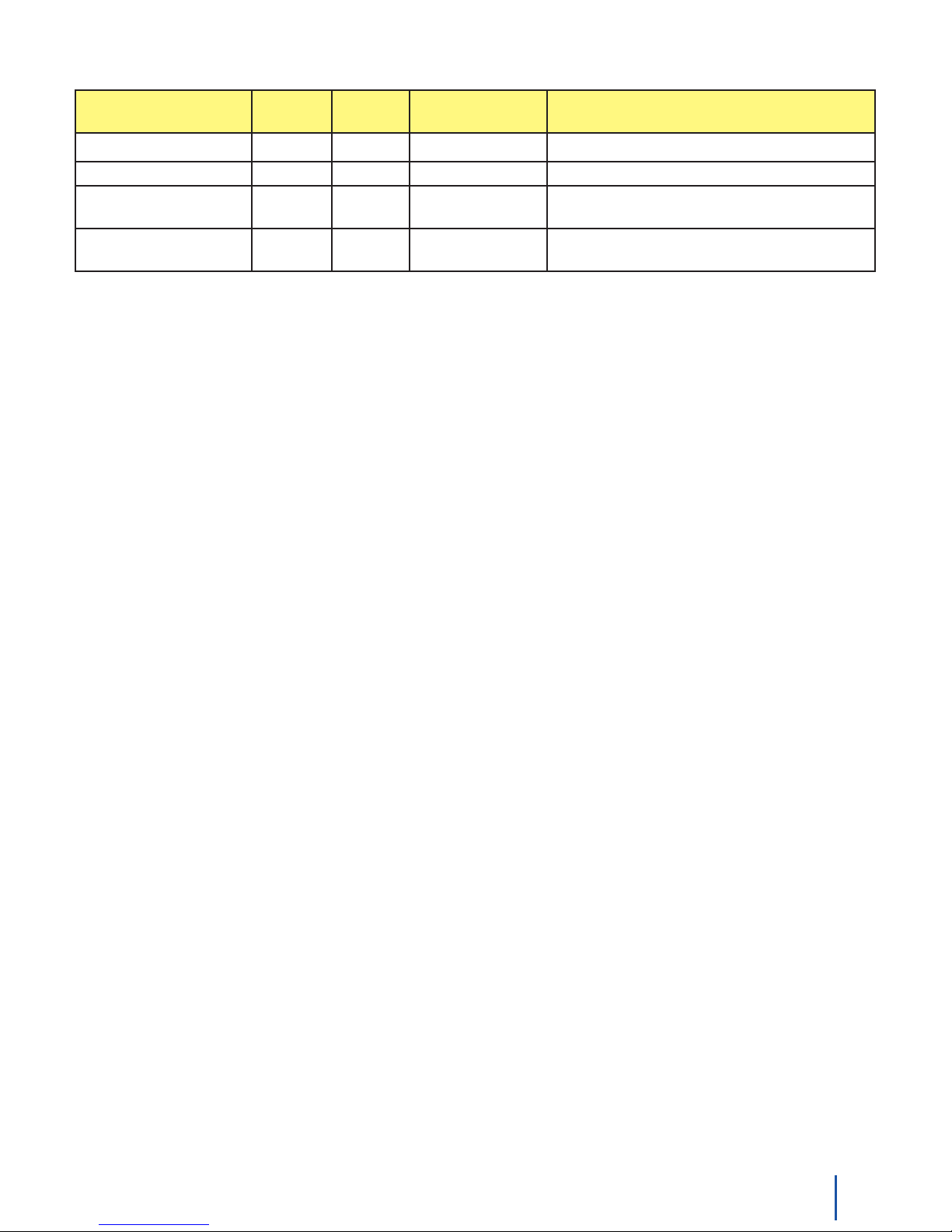
Product History
Date Board
Revision
July 2007 824 Product Release
September 2007 825 SPIOverclockingissuexed
May 2008 1 826 Added RC Filtering to Digital Inputs, PCB X
April 2010 2 900 2.1.6.20100406
Device
Version
Library Version Comment
Dimension increased to 3.27”
Congurabledatasamplingspeed.Replace
or later
USB connector with Mini-USB connector
Support
Call the support desk at 1.403.282.7335 8:00 AM to 5:00 PM Mountain Time (US & Canada) - GMT-07:00•
or
E-mail us at: [email protected]•
221018_2_Product_Manual - April 26, 2010
 Loading...