


Phenom User Manual
ProX / Pro / Pure
PW_Phenom_Pro_X_Pro_Pure_Print:PW_Phenom_G2_Pro_G2_Pure 19-11-13 20:54 Pagina 1

PW_Phenom_Pro_X_Pro_Pure_Print:PW_Phenom_G2_Pro_G2_Pure 19-11-13 20:54 Pagina 2

3
Things you must know
1. Introduction
2. System overview
3. Installing the
Phenom
4. Using the Phenom
CONTENTS
Things you must know 6
Introduction 8
1.1 Unpacking the Phenom components 8
1.2 Packaging contents 9
System overview 10
Controls 10
Connections 12
Screens 13
Installing the Phenom 18
Preparation 18
3.1 Requirements for positioning the Phenom components 18
3.2 Assembling the flat panel touch screen monitor 18
C
onnections 19
3.3 Connecting the Phenom 19
3.4 Activating the system 21
3.4.1 Switching on the Phenom 21
3.4.2 Switching ‘on’ the flat panel touch screen monitor 21
3.4.3 Calibrating the flat panel touch screen monitor 21
Using the Phenom 22
Preparation 22
4.1 Waking-up the Phenom 22
4.2 Preparing samples 22
4.2.1 Samples that cannot be prepared in colloidal graphite or silver paint 23
4.2.2 Particle samples 23
4.2.3 Polymers 24
4.2.4 Metals 24
4.2.5 Biological samples 24
4.2.6 Heavy metal coating 25
4.3 Loading samples 25
4.3.1 Activating the sample holder 26
Operation 26
4.4 Using the touch screen 27
4.5 Optical imaging 27
4.5.1 Adjusting focus 27
4.5.2 Adjusting brightness and contrast 27
4.5.3 Adjusting magnification (ProX / Pro) 28
4.5.4 Moving the sample 28
4.5.5 Sample overview 28
4.5.6 Storing images 28
4.6 Electron imaging 30
4.6.1 Adjusting focus 30
4.6.2 Adjusting brightness and contrast 31
4.6.3 Magnifying the image 31
4.6.4 Rotating the image 31
4.6.5 Moving the sample 32
4.6.6 Storing images 32
4.7 Viewing stored images 33
4.7.1 Comparing images (ProX / Pro) 34
4.7.2 Deleting stored images 34
4.8 Measuring on stored images (ProX / Pro) 35
PW_Phenom_Pro_X_Pro_Pure_Print:PW_Phenom_G2_Pro_G2_Pure 19-11-13 20:54 Pagina 3

4
4.9 Unloading the sample 35
4.10 Switching off the Phenom electron source 36
4.10.1 Switching off the Phenom 36
4.10.2 Switching off the flat panel touch screen monitor 37
4.10.3 Switching off the system completely 37
P
henom settings 37
75.1 Live viewing settings 37
5.1.1 Mode 37
5.1.2 Resolution 37
5.1.3 Quality 38
5.1.4 Intensity 38
5.2 Acquired image settings 38
5.2.1 Detector mode 38
5.2.2 Quality 39
5.2.3 Resolution 39
5.2.4 Presets 39
5.2.5 Storing user settings 40
5.3 Date and time 40
5.3.1 Adjusting the date 40
5.3.2 Adjusting the time 40
5.4 Databar / image type / UI mode 40
5.4.1 Databar 40
5.4.2 Image type 40
5.4.3 UI mode 41
5.5 Label 41
5.6 USB stick / Mode 41
5.6.1 USB stick 41
5.6.2 Mode 41
5.7 Advanced settings 42
5.7.1 SW (software) version 42
5.7.2 Shutdown 42
5.7.3 StoreSys(tem)Info 43
5.7.4 Routine pages 43
5.7.4.1 Source Tilt 43
5.7.4.2 Stigmate 44
5.7.4.3 Network 45
5.7.4.4 Connectivity 46
Maintenance 48
Troubleshooting 49
7.1 Error recovery and reporting 53
7.1.1 Rotary knob state indicator 53
7.1.2 Error messages and warnings 53
7.2 Power down 55
7.3 Rebooting the Phenom software 55
Preparing the Phenom for transport 56
8.1 Return procedure 56
8.2 Prepare for packing 56
8.3 Disconnecting and packing 57
Technical specifications 58
5. Phenom settings
6. Maintenance
7. Troubleshooting
8.
Preparing the
Phenom for
transport
9.
Technical
specifications
PW_Phenom_Pro_X_Pro_Pure_Print:PW_Phenom_G2_Pro_G2_Pure 19-11-13 20:54 Pagina 4

5
Phenom-World and the Phenom-World logo are registered trademarks of
Phenom-World Bv. Phenom
TM
is a trademark of Phenom-World BV.
Other product and company names mentioned herein may be the trademarks of their
respective owners.
This user guide was produced using XPress
®
document publishing software, a registered
trademark of Quark Technology and the Arial
TM
family of typefaces. Arial is a trademark of
The Monotype Corporation registered in the U.S. Patent & Trademark Office and may be
registered in other jurisdictions.
Ralph Schiedon
Joris Dobbelsteen
Sander Stoks
Jeroen Smulders
Karl Kersten
Koen Driessen
Karel van der Mast
Addo Hammen
Willem Theuws
Rob Rood (ROOD Text productions)
Copyright
© 2013 by Phenom-World BV
The information and materials contained herein are confidential and proprietary to
Phenom-World BV. They are provided for your organization’s internal use on a need to
know basis. They cannot be duplicated or disseminated for any third party without the
express consent of Phenom-World BV.
The information contained in this document has been composed with great care for quality,
reliabilty and accuracy and may be changed without notice.
Phenom-World BV will not accept liability for any consequence of use of this document.
Trademark
Acknowledgments
Production
Acknowledgments
Principal Contributors
Technical Publication
Disclaimer
PW_Phenom_Pro_X_Pro_Pure_Print:PW_Phenom_G2_Pro_G2_Pure 19-11-13 20:54 Pagina 5

6
CAUTION!
G
eneral Safety
I
mportant information
To avoid Fire or
Personal Injury
Things you must know
PleasereadalloftheseinstructionsbeforeyouoperatethePhenom.
Savetheseinstructionsforfuturereference.
Review the following safety precautions to avoid injury and prevent damage to the
Phenom microscope.
All safety and operating instructions must be read before the
microscope is operated, this is to avoid personal injury and prevent damage to the
Phenom.
To avoid potential hazards, use this product only as specified.
The user must not attempt to service the appliance beyond those means described in
the user's operating instructions.
All other servicing is to be performed by qualified service personnel.
Replace Fuse with identical type.
If a fuse is replaced, use the type as mentioned on the type plate.
G
round the Microscope.
The microscope is grounded through the grounding conductor of the power cord.
To avoid electrical shock the grounding conductor must be connected to earth ground.
Before using the microscope verify that the microscope is properly grounded.
Use correct power cord.
Only use the power cord specified for this product and approved for the country of
use.
Power Disconnect.
The power switch on the mains supply disconnects the microscope from the mains.
Do not block the power switch; it must be accessible to the user at all times.
Do not operate without covers.
The microscope must never be operated with the cover removed.
Do not operate the microscope with suspected failures or damaged covers.
If you suspect damage or failure of the product, do not disassemble this product.
Have it serviced by qualified and authorized service personnel. Servicing is required
when the microscope is damaged in any way, such as when the power supply cord or
the plug is damaged, liquid has been spilled in the microscope, it does not operate
normally or has been dropped.
Provide proper ventilation.
Adequate airflow must be allowed around the power supply and Phenom microscope
.
Do not block the ventilation openings. Respect at least 20 cm of free space to the
sides, the front, the back and the top of the Phenom microscope. Do not put materials
in the air gap between the Phenom microscope and the table.
Do not operate in wet and damp conditions.
The required room temperature and maximum humidity as specified in the system's
technical specifications (see chapter 9, ‘Technical specifications’) must be respected
at all times.
Do not operate in an explosive atmosphere.
Make sure that there is proper room ventilation such that the environmental air cannot
contain combustible gasses.
Do not use compressed-gas canisters in the vicinity of the system.
Propellants of canisters are very often combustible.
PW_Phenom_Pro_X_Pro_Pure_Print:PW_Phenom_G2_Pro_G2_Pure 19-11-13 20:54 Pagina 6

7
Environmental
aspects
Notes!
Equipment recycling
To reduce the use of natural resources and to avoid the release of substances that
could be harmful to the environment or human health we advise you to recycle this
product.
For information about recycling options please contact Phenom-World’s Customer
Support.
Disposal of your old product
Y
our product is designed and manufactured with high quality materials and
components, which can be recycled and reused.
When this crossed-out wheeled bin symbol is attached to a product it means the
product is covered by the European Directive 2002/96/EC.
Please act according to your local rules and do not dispose of your old products with
your normal household waste. The correct disposal of your old product will help
prevent potential negative consequences for the environment and human health.
Equipment classification
The Phenom should be used indoor in a controlled electromagnetic environment.
The Phenom electron microscope is CE compliant with the following directives:
– 73/023/EEC Low Voltage Directive
– 89/336/EEC Electromagnetic Compatibility Directive
– 96/29/EURATOM Ionizing Radiation Directive following article 3.2 e.
Using the following standards:
EN61010-1 Safety measurements for electrical equipment for measurement, control and
laboratory use.
EN61326-1 Electrical equipment for measurement, control and laboratory use – EMC
requirements (industrial level) and that the X-ray emission is below 1 µSv/h at 10 cm
distance from the surface
Phenom microscopes are classified as:
• Safety class 1 (EN 61010-1)
• Pollution class 2 (EN 61010-1)
• Installation (Overvoltage) category 2 (EN 61010-1)
• Plug connected
– EMC ElectroMagnetic Compatibility
– Licensing or registration for X-ray might be required according to local regulations.
For most of Europe no licensing or registration is necessary (see 96 / 29 / Euratom
directive, para. 3.2.e).
PW_Phenom_Pro_X_Pro_Pure_Print:PW_Phenom_G2_Pro_G2_Pure 19-11-13 20:54 Pagina 7
8
Preparation
Unpacking
Caution!
1. Introduction
Congratulations on your purchase of the PhenomTMmicroscope. The PhenomTMis a high
resolution desktop imaging tool that combines an optical camera for never-lost navigation
and a high quality scanning electron microscope (SEM) for detailed imaging to bring a
completely new approach to microscopy.
The Phenom’s innovative user interface utilizes intuitive touch screen controls which allows
users to observe superb quality images with minimal operator training.
The Phenom can handle a wide range of samples with minimal preparation.
We are sure that if used properly, the Phenom will bring you years of enjoyment.
You will want to keep this user manual handy, as it is a convenient source of information
about the Phenom.
1.1 Unpacking the Phenom components
Make sure the room where the Phenom components are to be placed is clean and dry
and that room temperature is between 15 °C and 30°C (59 °F and 86°F).
Room humidity should not exceed 80% RH.
Avoid direct sunlight, vibrations and strong magnetic fields.
Also refer to chapter 3.1 ‘Requirements for positioning the Phenom components’.
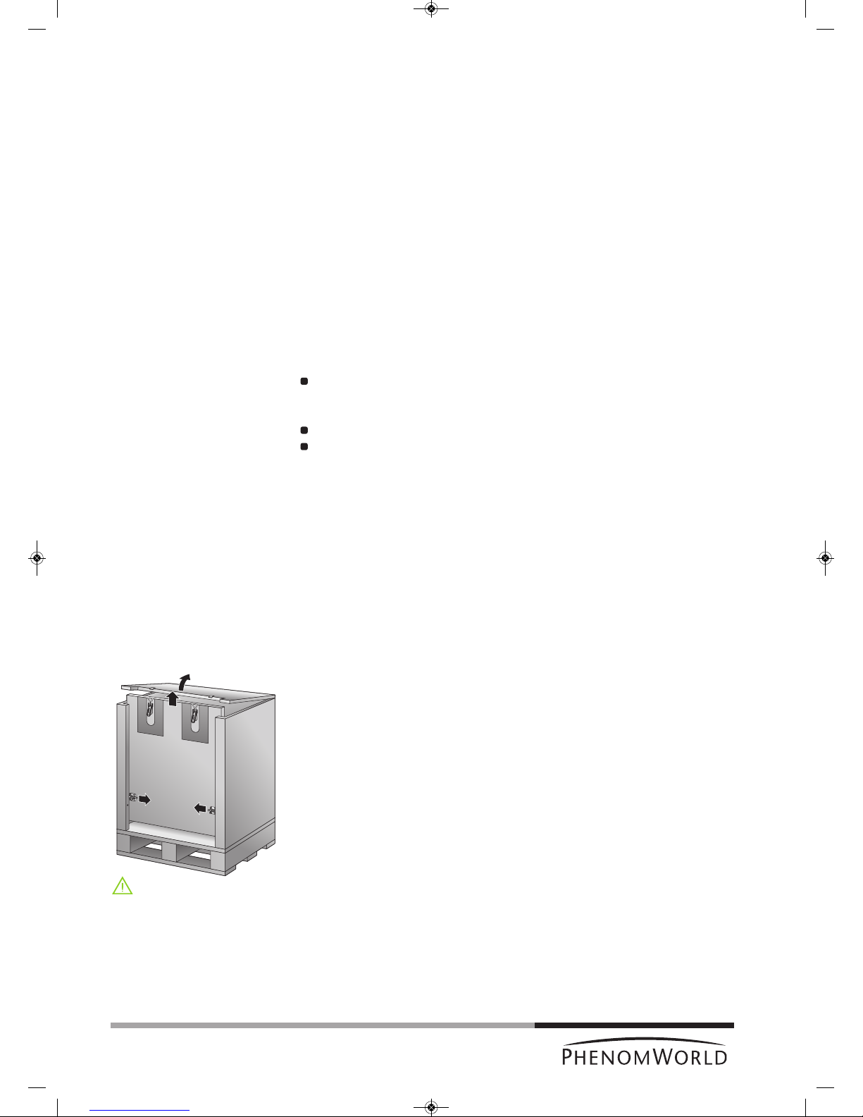
1 First inspect the packaging before opening it. If the packaging is damaged or if the
locks are open, we recommend that you report this to Phenom-World’s Customer
Support:
- address: Dillenburgstraat 9E
5652 AM Eindhoven
The Netherlands
- e-mail: service@phenom-world.com
- phone: +31 (0)40 259 73 72
- fax: +31 (0)40 259 73 71
- opening hours: Monday - Friday, 09:00 - 17:00 (CET, GMT +1)
It is however very likely that, despite slight damage to the packaging, the Phenom
components are still in good condition.
2 Open all 4 locks and open the top cover completely.
3 Remove the front panel by lifting it upwards.
4 Remove all loose foam parts.
5 Lower the plastic bag and remove the Phenom microscope.
Due to the weight, it is recommended that two people, one on each side, lift the
Phenom out of the box. Donot lift from the front as the door could easily be
damaged. Donot lift by the plexiglass frontcap or by the door handle.
6 Confirm that all Phenom components are present. For a complete list of components,
refer to chapter 1.2 ‘Packaging contents’.
7 Take the boxes out of the other compartment.
8 Unpack all accessories prior to installation.
PW_Phenom_Pro_X_Pro_Pure_Print:PW_Phenom_G2_Pro_G2_Pure 19-11-13 20:54 Pagina 8
9
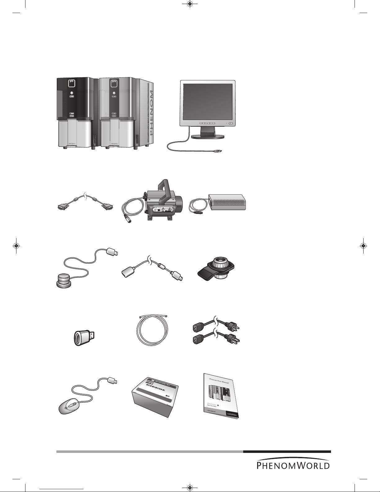
1.2 Packaging contents
Please verify that the Phenom box contains the following items. They are provided to help
you set up and use the Phenom. If any of these items are missing or damaged, contact your
dealer immediately.
Save the packaging materials in case you need to transport the Phenom.
Phenom microscope ProX / Pro / Pure - 17" flat panel touch screen monitor (Pure)
- 19" flat panel touch screen monitor (ProX / Pro)
Flat panel touch screen Pre-vacuum pump Power supply
monitor VGA cable
Rotary knob Rotary knob Sample holder
extension cable
USB Flash drive Pre-vacuum pumphose - Power cable Europe 2 x
- Power cable US 2 x
Mouse (ProX / Pro) Phenom Starter Kit User manual
PW_Phenom_Pro_X_Pro_Pure_Print:PW_Phenom_G2_Pro_G2_Pure 19-11-13 20:54 Pagina 9
C
ontrols
Phenom microscope
Mouse
(Pro)
Rotary knob
USB Flash drive
2. System overview
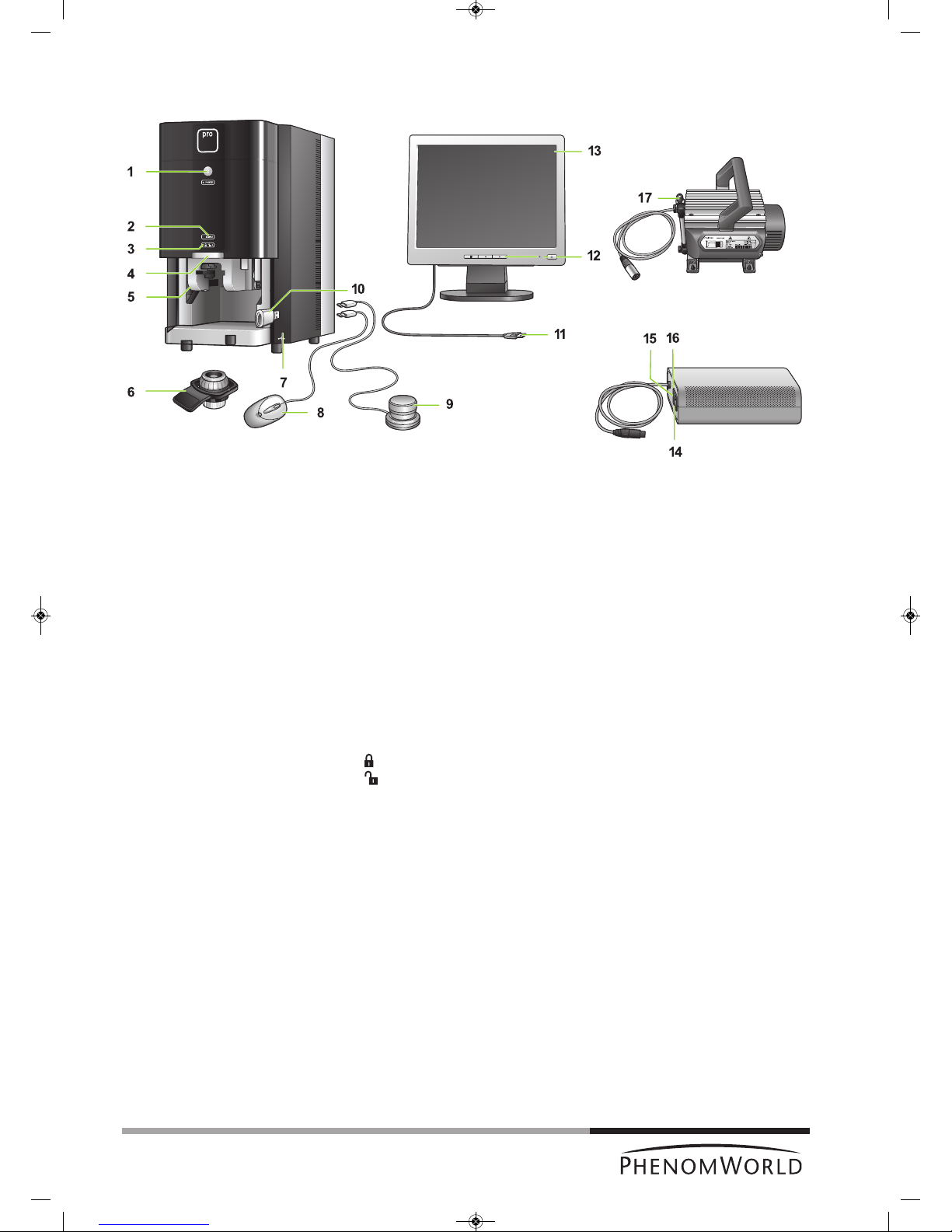
1 y System control button
- Switches the Phenom from standby or hibernate mode to operation mode.
- Switches the Phenom from operation mode to standby.
POWER
- Blinks green when the Phenom power supply is switched on and the Phenom goes
to operation mode.
- Blinks green when the Phenom switches from standby or hibernate mode to
operation mode.
- Lights up orange in standby mode.
- Blinks orange (1 second on, 3 seconds off) in hibernate mode.
- Lights up green in operation mode.
2 SAMPLE (sample indicator)
Lights up green when a sample is loaded.
3 - Lights up orange when the door is locked.
- Lights up green when the door is unlocked.
4 Door
5 Sample loading bay
To insert the sample holder into the Phenom.
6 Sample holder
7 USB ports
- To insert the supplied USB Flash drive.
- To insert the mouse USB connector or the rotary knob USB connector.
8 Operates the Phenom together with the touch screen and the rotary knob.
9 Operates the Phenom together with the touch screen and the mouse (ProX / Pro).
10 To store images on.
10
Fig. 1
PW_Phenom_Pro_X_Pro_Pure_Print:PW_Phenom_G2_Pro_G2_Pure 19-11-13 20:54 Pagina 10

11
Flat panel touch
screen monitor
Power supply
Pre-vacuum pump
11 USB cable
Connects the monitor to the Phenom (rear) USB port.
12 Monitor controls
y - switches the monitor on and off.
LED - lights up green when the monitor is switched on.
Displays monitor menu and selects menu items.
– and +
Navigate through and adjust monitor settings.
13 Touch screen
Operates the Phenom together with the rotary knob and the mouse (ProX / Pro).
14 0 / I switch
15 Connection for power cable
16 Fuse holder
Contains the fuses.
17 Connection for pre-vacuum pumphose
PW_Phenom_Pro_X_Pro_Pure_Print:PW_Phenom_G2_Pro_G2_Pure 19-11-13 20:54 Pagina 11
12
Connections
Phenom microscope
Flat panel touch
screen monitor
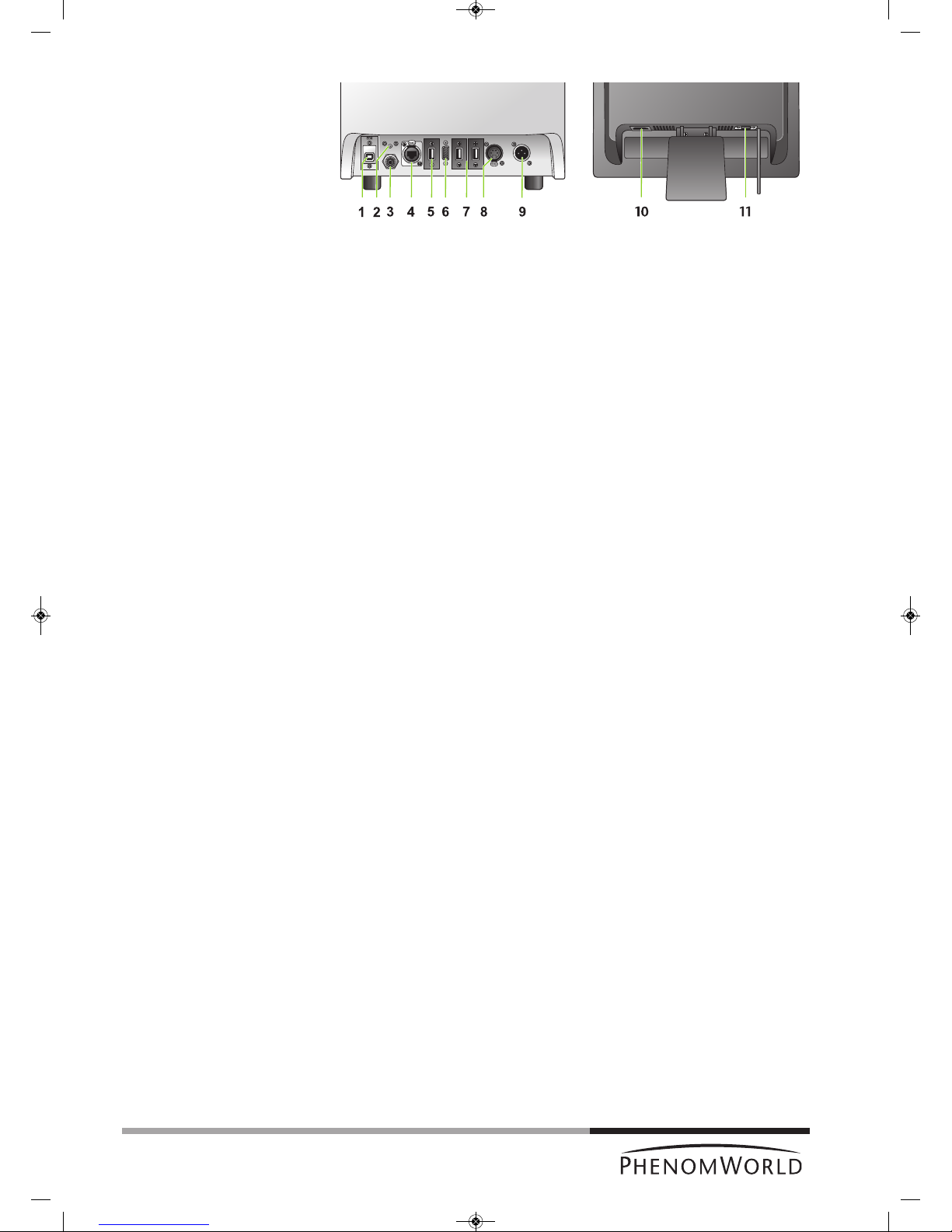
1 EDX / USB port
Connects the Phenom EDS (Energy Dispersive Spectroscopy) detector to the
ProSuite EeeBox PC (ProX).
2 Reset button
Reboots the Phenom software.
3 Connection for pre-vacuum pumphose
Connects the Phenom to the pre-vacuum pump.
4 Ethernet connector
Connects the Phenom to the Local Area Network.
PUSH button
Opens the ethernet connector.
5 USB port
Connects the Phenom to the monitor USB port.
6 VGA connector
Connects the Phenom to the monitor VGA connector.
7 USB ports
Connect the Phenom to the rotary knob and the mouse (ProX / Pro) and the ProSuite
for ProX.
8 Power connector (out)
Connects the Phenom to the pre-vacuum pump.
The Phenom supplies power to the pre-vacuum pump.
PUSH button
Opens the power connector.
9 Power connector (in)
Connects the Phenom to the power supply.
10 Power connector (in)
Connects the monitor to the mains outlet.
11 VGA connector
Connects the monitor to the Phenom VGA connector.
Fig. 2
Rear view: microscope (left) and monitor (right)
PW_Phenom_Pro_X_Pro_Pure_Print:PW_Phenom_G2_Pro_G2_Pure 19-11-13 20:54 Pagina 12
13
S
creens
Screens
selection bar
Image screen
IMAGE – selects Image screen.
ARCHIVE – selects Archive screen.
SETTINGS – selects Settings screen.
ADVANCED – selects Advanced settings screen. Refer to 5. ‘Phenom settings’.
? – when ’?’ is pressed, the Help function is enabled and a balloon with
information appears when any other button is touched. The balloon
gives information about the function of the button.
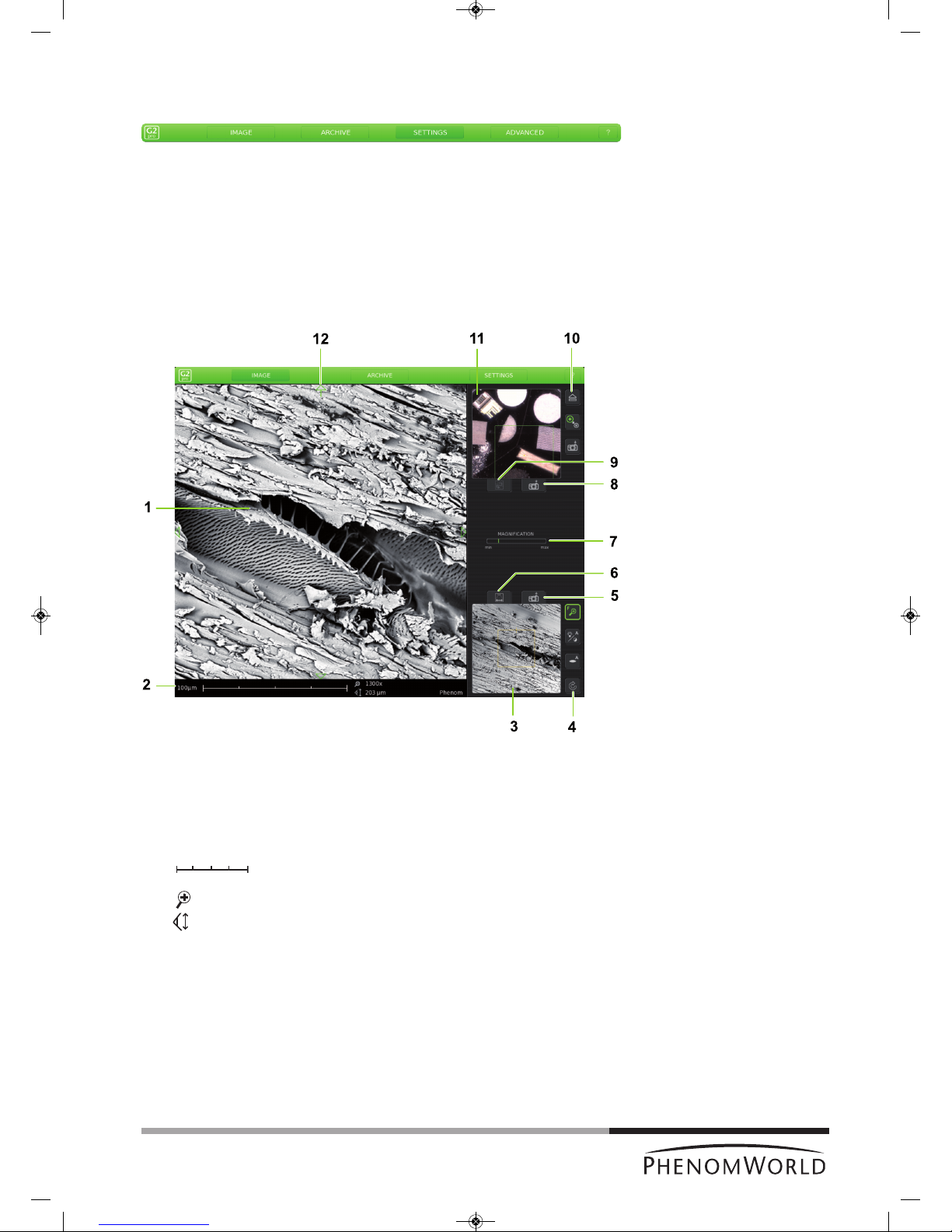
The Image screen is used to view samples, take pictures, and operate the Phenom.
1 Main viewing window
Displays magnified part of the sample.
2 Data bar
10 µm – current ruler size.
– dynamic representation of ruler size
(depending on magnification factor)
. . . . x – magnification factor.
. . . . µm – Field Of View (total picture size).
FEB 092006 12 : 15 PM – Date and time.
IMG S121206_0012 – Sample / file name.
Items to be shown can be selected on the Settings screen.
Fig. 3
PW_Phenom_Pro_X_Pro_Pure_Print:PW_Phenom_G2_Pro_G2_Pure 19-11-13 20:54 Pagina 13

14
3 Electron overview window
Displays the part of the sample that is magnified in the main viewing window, with the
largest field of view (lowest magnification factor).
4 Button bar
The buttons define the functionality of the rotary knob:
-
Magnifies part of the image.
- Adjusts overall contrast of the image.
- Adjusts brightness of the image.
- Adjusts focus of the image.
- Rotates the image (electron imaging mode only).
5 - Takes a picture of the image in the electron overview window.
6 - Refreshes the electron overview window.
7 Status window
- Gives information on the current status of the Phenom.
- Displays messages during operation, when problems occur or when action by the
user is required.
Progress bar
- Indicates the remaining time when the Phenom is performing durative actions.
- Indicates the remaining wake-up time when the Phenom is waking up from standby
and hibernate mode.
8 - Takes a picture of the image in the optical overview window. Refer to ‘11. Optical
overview window’.
9 - Makes a composite image overview of the entire sample area.
10 Button bar
- Transfers sample from loading position to optical imaging position and vice-
versa.
- Selects electron imaging or optical imaging .
The appropriate circle lights up green to indicate the active mode.
- Replaces when the Phenom is waking up from standby or hibernate mode
and indicates the progress of the wake-up process.
- Takes a digital picture of the image in the main viewing window.
11 Optical overview window
- Displays the part of the sample that is magnified in the main viewing window.
-
Displays composite image overview of the entire sample area.
12
Move the sample in up, down, left and right direction.
PW_Phenom_Pro_X_Pro_Pure_Print:PW_Phenom_G2_Pro_G2_Pure 19-11-13 20:54 Pagina 14

15
Archive screen
The Archive screen is used to view, compare and delete sample images stored on the
USB Flash drive or on a Windows network share.
1 Main viewing window
Displays currently selected image
2 Data bar
3 Thumbnail gallery
Shows your pictures in thumbnail format.
4 Scroll bar
Move the slider to scroll through your images.
5 Button bar
- Ejects sample and allows door to be opened.
- Deletes selected image.
- Holds the selected image so it can be compared with other images.
- Activates the measuring function.
- Stores a copy of a measured image on USB Flash drive or network share,
including measurement data.
- Shows archive images stored on the USB Flash drive ( ) or network share
( ). This button is only operational when both storage locations are available
and valid network settings have been set in the Settings screen. For this refer to
4.5.5 ‘Sample overview’ and 4.6.6. ‘Storing images’.
- Digital zoom: digitally magnifies the stored image.
- Scrolls through your stored images.
Fig.4
PW_Phenom_Pro_X_Pro_Pure_Print:PW_Phenom_G2_Pro_G2_Pure 19-11-13 20:54 Pagina 15

16
Settings screen
Notes!
The Settings screen allows you to adjust the various Phenom settings to suit your own
personal preferences. For this refer to 5. ‘Phenom settings’.
1 Live viewing
Adjusts and stores viewing conditions such as imaging mode, pixel resolution and
averaging speed.
2 Date and time adjustment
Adjusts date and time.
3 USB / network
Selects USB Flash drive (USB) or network share (network) to store images.
4 Data bar
Selects the items to be displayed in the data bar in the main viewing window and / or
on the saved images.
Image type
Selects file format for stored image.
5 U(ser) I(nterface) mode
Selects the desired User Interface mode. Select whether the button bar on the Image
screen will be placed on the left or on the right side of the screen.
6 Source
Displays the total time the Phenom electron source has been operational.
Only visible when Advanced is activated. Refer to 11 ‘Advanced’).
– When the Phenom electron source is replaced, the timer will start counting again from
zero. Operating hours of the previous source will not be taken into account.
– When new software is installed on the Phenom, the timer will copy the operating
hours from the previous software versions.
7 Label
Enter image / file name. Refer to 5.5 ‘Label’.
Fig.5
PW_Phenom_Pro_X_Pro_Pure_Print:PW_Phenom_G2_Pro_G2_Pure 19-11-13 20:54 Pagina 16

17
8 SW version
Shows current Phenom software version.
Previous
Shows previous Phenom software version.
Rollback
Returns to previous software version.
S
hutdown
Prepares the Phenom for complete switch-off.
StoreSysInfo
Stores a file with the current system information on the USB Flash drive (fig. 1,10).
SW version, Previous, Rollback, Shutdown and StoreSysInfo are advanced
settings that can be accessed by touching the Advanced button (11) and entering the
log-in password. Only visible when Advanced is activated. Refer to 11 ‘Advanced’.
9 Mode
Switches the Phenom to standby or hibernate (power saving) mode.
10 USB stick
Formats USB Flash drive or delete content on USB Flash drive.
11 Sample holder
Displays the sample holder name when an activated sample holder is inserted.
No sample holder inserted lights up when:
- you start imaging without a sample holder inserted.
- the inserted sample holder needs to be activated. Refer to 4.3.1 ‘Activating the
sample holder’.
12 Advanced
Protected login modes for experienced users.
13 Acquired image
Adjusts and stores settings such as pixel resolution, picture quality and detector mode
for images to be saved.
PW_Phenom_Pro_X_Pro_Pure_Print:PW_Phenom_G2_Pro_G2_Pure 19-11-13 20:54 Pagina 17

P
reparation
Note!
CAUTION!
3. Installing the Phenom
The indications between brackets behind button and connector names refer to the items in
the overview illustrations on pages 10 - 17. E.g. (fig. 2,3) refers to item 3 in figure 2.
3.1 Requirements for positioning the Phenom
components
Place the Phenom, touch screen, pre-vacuum pump and power supply on a flat,
steady surface, out of direct sunlight and away from sources of excessive dust, dirt,
heat, water, moisture, vibration, and strong magnetic fields.
Place both the power supply and pre vacuum pump either on the floor or on the table
near to where the Phenom microscope is placed.
Make sure that the adapter 0 / I switch (fig. 1,14) switch is accessible at all times.
Make sure the Phenom power supply is switched off before making any connections.
Recommended table size is 120 x 75 cm (47" x 29.5") with a load rating of 100 kg
(220.5 lbs).
Allow sufficient cooling of the Phenom, power supply and pre-vacuum pump by
keeping all cooling vents clear of obstructions.
Make sure room temperature is between 15 °C and 30 °C
(59 °F and 86 °F) and that room humidity does not exceed 80% RH.
Position the touch screen in such a way that you avoid glare or reflections from
overhead lighting or outside sources of light.
Keep the screen clean and set brightness and contrast to a level that enables you to
see the screen clearly. For cleaning the screen, refer to 6. ‘Maintenance’ and for
setting brightness and contrast, use the and – / + buttons (fig. 1, 12) on the
monitor.
When positioning the Phenom always work with two persons, one at each end.
3.2 Assembling the flat panel touch screen
monitor
Place the monitor foot onto the desktop stand.
Position the monitor above the foot and align the connectors. Gently press until the
foot clicks into position.
18
PW_Phenom_Pro_X_Pro_Pure_Print:PW_Phenom_G2_Pro_G2_Pure 19-11-13 20:54 Pagina 18

Connections
Note!
1
4
1
4
3.3 Connecting the Phenom
The figures between parentheses refer to the corresponding figures in the illustration.
1 Connect the pre-vacuum pumphose (1) between the pump inlet and the Phenom
pre-vacuum pump connector.
Place the nut at one end of the hose onto the pump inlet screw thread and the nut
at the other end of the hose onto the pump connector screw thread.
Turn both nuts clockwise until they are finger tight.
Use a 13 mm (0.51") spanner (wrench) to tighten the nut at the pump side.
It takes 1 to 1.5 full turn to properly tighten the nut.
Tighten the nut at the other end of the hose, using a 14 mm (0.51") spanner
(wrench).
2 Connect the pump power cable (2) to the Phenom pump output connector.
> The Phenom will now provide power to the pre-vacuum pump.
To remove the pump power cable, first press the PUSH button to open the power
connector.
3 Connect the monitor VGA cable (3) between the monitor
VGA connector and the Phenom VGA connector.
1
5
1
4
19
PW_Phenom_Pro_X_Pro_Pure_Print:PW_Phenom_G2_Pro_G2_Pure 19-11-13 20:54 Pagina 19

20
Note!
4 Connect the monitor USB cable (4) to the USB port at the rear of the Phenom.
5 Connect the power cable (5) of the power supply to the Phenom power connector.
6 Connect the power cable (6) of the power supply to a wall outlet.
7
Connect the monitor power cable (7) to a wall outlet.
8 Connect the USB connector of the rotary knob (8) to one of the twin USB ports at the
rear of the Phenom. If necessary, use the rotary knob extension cable.
9 Connect the USB connector of the mouse (9 - ProX / Pro) to the other twin USB port.
10 Connect the USB Flash drive (10) to one of the USB ports at the Phenom front.
11 Optionally you can connect an ethernet cable (not supplied) between the Phenom
Ethernet connector and your router / gateway or cable modem.
If the Phenom is connected to the Internet, the technical performance of the Phenom
will be monitored by Phenom-World’s Customer Support.
This increases the predictability of maintenance requirements and ensures greater
uptime (the time the Phenom is ‘up’ and running) for your Phenom.
Connect an ethernet cable (11) between the Phenom Ethernet connector and
your router / gateway or cable modem.
> The Phenom will now try to acquire an IP (Internet Protocol) address via DHCP
(Dynamic Host Configuration Protocol).
To remove the ethernet cable, first press the PUSH button (12) to open the
Ethernet connector.
To activate this function, refer to chapter 5.7.4 ‘Routine Pages - Remote
Assistant’.
Sometimes assignment of IP addresses is MAC address based. A Media Access Control
(MAC) address is a unique identifier, attached to most network adapters. It is a number that
acts like a name for a particular network adapter.
Some companies assign IP addresses to known MAC addresses only, in order to avoid any
non-company computer accessing the network or infecting the network with viruses.
When a MAC address is required, please contact Phenom-World’s Customer Support:
- address: Dillenburgstraat 9E
5652 AM Eindhoven
The Netherlands
- e-mail: support@phenom-world.com
- phone: +31 (0)40 259 73 72
- fax: +31 (0)40 259 73 71
- opening hours: Monday - Friday, 09:00 - 17:00 (CET)
PW_Phenom_Pro_X_Pro_Pure_Print:PW_Phenom_G2_Pro_G2_Pure 19-11-13 20:54 Pagina 20

21
3.4 Activating the system
3.4.1 Switching ‘on’ the Phenom
1 Make sure all connections are properly made.
2 Set the 0 / I switch (fig. 1,14) on the power supply to I.
> The system starts up automatically.
The pre-vacuum pump noise fades away after approximately 1 minute. Refer to
7. ‘Troubleshooting’ if this is not the case.
> The POWER LED (fig. 1,1) blinks green.
> It takes between 30 minutes and 14 hours before the system is fully operational.
The start-up time depends on the time the system has been switched off.
Refer to 7.2 ‘Power down’.
3.4.2 Switching ‘on’ the flat panel touch screen monitor
Press y (12) on the monitor.
> The power LED (fig. 1,11) lights up green.
> The Phenom splash screen appears, followed by the Image screen or the
C
alibration screen.
3.4.3 Calibrating the flat panel touch screen monitor
Calibrating the monitor optimizes the performance of the touch screen and has to be done
only once. When the monitor is connected and switched on for the first time the calibration
screen appears automatically.
1 Press
y (12) on the monitor to switch on the monitor.
2 Press the center of the cross that is displayed on the screen.
> The cross disappears and then appears again on a different location on the screen.
The cross will appear on four different locations.
3 Press the center of the cross on all four locations it appears.
> After pressing the cross for the fourth time the monitor is calibrated and ready to
operate the Phenom.
> After the calibration procedure, the normal Phenom UI (User Interface) is shown
again.
– If you wish to redo the calibration process you can call up the calibration screen again
by pressing the rotary knob (fig. 1,9) for 15 seconds.
PW_Phenom_Pro_X_Pro_Pure_Print:PW_Phenom_G2_Pro_G2_Pure 19-11-13 20:54 Pagina 21
22
P
reparation
Note!
Notes!
Important!
What do you need?
4. Using the Phenom
The indications between brackets behind button and connector names refer to the items in
the overview illustrations on pages 10 - 17. E.g. (fig. 2,3) refers to item 3 in figure 2.
4.1 Waking-up the Phenom
After one hour of inactivity, the Phenom switches to standby. The POWER LED (1) lights up
orange. After 72 hours of inactivity, the Phenom switches to hibernate (power saving) mode.
The POWER LED (1) blinks orange (1 second on, 3 seconds off).
To wake up the Phenom from standby / hibernate mode:
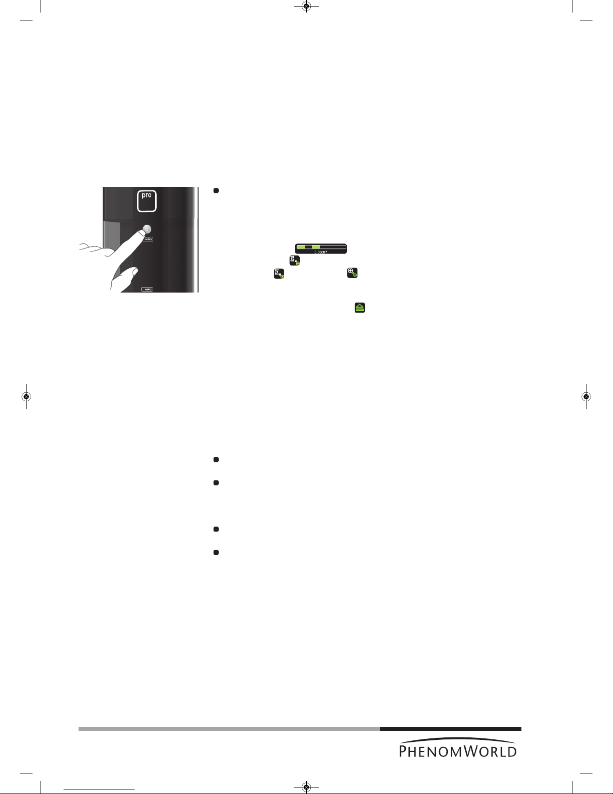
Press the System control button y (fig. 1,1).
> The POWER LED (fig. 1,1) blinks green until the Phenom is completely activated
again. From standby mode this will take approximately 4 minutes; from hibernate
mode this will take approximately 6 minutes.
> The Phenom is immediately ready for optical imaging. Refer to 4.5 ‘Optical imaging’.
> A progress bar ( ) displays the remaining wake-up time.
> An hourglass ( ) indicates that the wake-up process is in progress.
W
hen the icon changes into , the Phenom is ready for electron imaging.
Refer to 4.6 ‘Electron imaging’.
– The Phenom is also activated when (fig. 3,9) on the IMAGE screen is touched
during sample loading. Refer to 4.3 ‘Loading samples’.
– When the message ‘Check connectivity settings’ appears in the status window
(fig. 3,7), you should check your connectivity settings. Press the check button (4) that
appears to continue. Also refer to chapter ‘Connectivity’ under 5.7 ‘Advanced settings’
and / or Phenom Remote Assistant (PRA) Operations Guide.
4.2 Preparing samples
This chapter is meant to give you better understanding of sample preparation before using
samples inside the Phenom. By following the guidelines below you can maximize sample
resolution and eliminate possible maintenance issues.
The Phenom can accommodate samples up to 25 mm (1") in diameter and
30 mm (1.1811") in height.
Never put wet samples in the Phenom. Wet samples will readily outgas under
vacuum. This can cause serious problems in your imaging capabilities and can cause
permanent damage to the Phenom. Make sure samples have been dried before
placing them into the machine.
Be absolutely sure there are no loose particles on the sample before loading it into
the Phenom by slightly flushing it with compressed air.
Always make sure the sample is firmly fastened to the sample stub. Moving a sample
from atmosphere to vacuum can cause loose sample material to become dislodged
from the stub. This debris can make its way up the SEM column and distort the
electron beam. The general sample preparation section hereafter explains how to
properly prepare samples for the Phenom. This will ensure higher quality imaging and
reduce maintenance issues.
For sample preparation you will need to have the following items available:
– sample stub (less than 25 mm (1") in diameter);
– stub gripping tweezers;
– standard tweezers;
– stub tray;
– toothpick (or other disposable pointed object);
– one of the following items: colloidal graphite, silver paint, or double sided carbon
adhesive pads;
– a can of compressed air.
PW_Phenom_Pro_X_Pro_Pure_Print:PW_Phenom_G2_Pro_G2_Pure 19-11-13 20:54 Pagina 22

23
General guidelines
Caution!
1 Begin by placing a bare stub into a sample tray. Never prepare a sample in the
Phenom sample holder for loose particles may end up in the container.
2 Colloidal graphite or silver paint can be used to cement the sample down to the
sample stub. Polymers, insects, and MEMS devices are some examples of samples
that are large enough to affix to a stub using colloidal graphite or silver paint. For
smaller objects like pollen, powders, and TEM grids it is advised to avoid using this
m
ethod as it may submerge the sample before drying.
Also note that once colloidal graphite and silver paint come in to contact with the
sample, they cannot be removed.
For smaller samples, or samples that may need to be removed from the sample stub
after imaging, skip to step 1 of chapter ‘Samples that cannot be prepared in colloidal
graphate or silver paint’.
3 Begin by opening the bottle of graphite or silver paint in a well ventilated area.
4 Take a fine point disposable object such as a toothpick or pin and dip the tip into the
silver paint or graphite. Remove the tip from the liquid and dab the residual graphite
or silver paint onto the bare stub.
5 Replace the lid onto the jar of graphite or silver paint as these will dry out quickly.
6 The liquid will dry quickly so be aware of time during the next three steps.
7 Take the standard tweezers and firmly clamp the sample.
8 Move the sample to a bare area of the stub. Do not place the sample directly into the
liquid.
9 Gently slide the sample into the drop of liquid so that the liquid beads around the
bottom of the sample. Once a desired level or surface contact between the liquid and
sample has been attained, let the liquid dry for 5-10 minutes. The sample is now
ready to image.
4.2.1 Samples that cannot be prepared in colloidal
graphite or silver paint
1 For these samples, a double sided adhesive can be used. Although these adhesive
pads are not quite as conductive as the silver or graphite, they are much easier to use
for a broader spectrum of samples. To begin, peel back the coating on top of the
adhesive with tweezers.
2 Place a clean stub on top of the exposed adhesive. Pull the stub off the adhesive
sheet to expose the other side of the adhesive pad.
3 Now place the sample on top of the exposed adhesive. Make sure the sample is
firmly attached to the stub before placing the sample into the Phenom.
4.2.2 Particle samples
Particles include but are not limited to powders, pollen, small filings, diatomaceous material,
and other dust-like matter.
1 To prepare a particle sample, attach a double sided adhesive pad to a bare sample
stub. See ‘General guidelines’.
2 Take a toothpick, tweezers, or other fine point object and collect some of the particle
sample on the tip. Brush the sample coated tip against the exposed adhesive of the
sample stub. Take the flat side of the toothpick or tweezers and press the particles
firmly against the adhesive pad.
3 Grip the sample with stub holding tweezers and forcibly tap the stub on the side of a
table or bench to remove loose particle from the sample stub.
4 With a can of compressed air, spray the surface of the sample to remove any other
loose particles.
> The sample is now ready to be placed into the Phenom.
5 Repeat steps 3 and 4 when re-imaging a prepared particle sample.
PW_Phenom_Pro_X_Pro_Pure_Print:PW_Phenom_G2_Pro_G2_Pure 19-11-13 20:54 Pagina 23

24
4.2.3 Polymers
Polymer samples include plastics and glass and are typically mounted flat or on a
c
ross section.
Because of their organic and / or siliceous composition, polymers also tend to charge
even at low magnifications and accelerating voltages.
A light gold coating can eliminate most charging effects and optimize resolution.
Polymers should be fixed down to the sample stub with colloidal graphite, silver paint,
double sided carbon pad, or a clamping mechanism.
4.2.4 Metals
Samples containing metal may have a certain affinity for the electromagnets within
the SEM. This affinity may be strong enough to pull the sample from the stub and up
into the detector region. This will cause degradation of imaging capability and will
require a service technician to remove this material from the detector.
To avoid this scenario, all metal samples should be firmly fastened to the SEM stub.
Metalpowders can be fastened to the SEM stub in the same fashion as
non-metal powders. Please reference the 4.2.2 ‘Particle
samples’ section for instructions.
M
etalfilings can be attached to the stub in a similar fashion to metal
powders. However, larger filings should be attached using
colloidal graphite or even a clamping stub.
Ferrous, or iron-containing samples should be mounted onto an SEM stub with great
care. There are several powerful electromagnets inside the SEM that will attract iron
containing materials within the sample chamber. Loose ferrous material can be pulled
off the sample and onto the detector. This will cause a considerable, if not total, loss
of imaging capability and can seriously damage the detector. Make sure the sample is
firmly attached to the sample stub with colloidal graphite, silver paint, adhesive pad,
or a clamp before imaging in the SEM.
4.2.5 Biological samples
Biological samples may be more difficult for SEM imaging.
High vacuum, low conductivity, and regular outgassing are all factors that reduce the
clarity of biological samples in the SEM.
To best image biological samples make sure the sample is dry.
Here are a few methods of sample preparation for the Phenom.
AirDrying will remove a fair amount of moisture from a biological
sample allowing for better imaging. The drawback to air
drying is that surface morphology of the sample is sacrificed.
CriticalPointDrying(CPD) is a complex way of drying biological samples without
seriously disrupting surface morphology. Although
sample preparation time will greatly increase with the
use of CPD, samples will look much truer to their
original state than with air drying.
HeavyMetalStaining using heavy metals such as osmium can be used for
samples to be imaged in the Phenom. Heavy metal staining
is also a complicated and potentially hazardous form of
sample preparation. This type of preparation should only be
attempted by a trained individual in an appropriate lab
environment.
Biologicalsamples are also fairly non-conductive and may charge under the
SEM. A gold coating can reduce charging in these types of
samples. Refer to 4.2.6 ‘Heavy Metal Coating’.
PW_Phenom_Pro_X_Pro_Pure_Print:PW_Phenom_G2_Pro_G2_Pure 19-11-13 20:54 Pagina 24
25
4.2.6 Heavy metal coating
For materials that display a charging effect under the SEM, a coating of gold or other
h
eavy metal will most likely improve imaging capability. Remember, it is best to begin
with a light coat to reduce charge but more importantly to minimize change in surface
morphology of your sample.
Because every sputter coater is different, experiment with various coating times and
currents to optimize imaging performance.
4.3 Loading samples
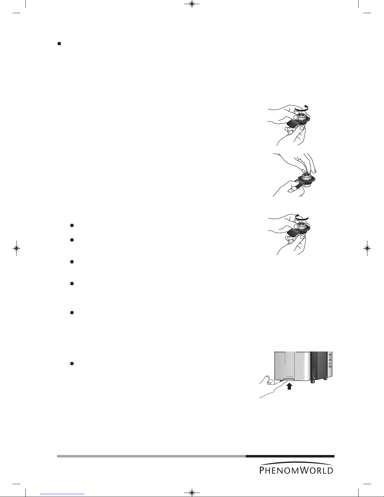
1 Make sure that the sample is properly mounted and immobilized on the stub.
2 Turn the height adjustment ring of the sample holder counter-clockwise until the
mounting surface is in the highest position.
3 Insert the stub pin into the hole on the mounting surface, using tweezers if necessary.
4 Make sure that the stub is inserted in such way that the flat of the stub is seated on
the mounting surface.
5 Lower the sample by turning the height adjustment ring clockwise.
The sample is positioned correctly if it is at least 2 mm (0.08") below the top
surface of the holder.
Each one of the vertical marks on the adjustment ring corresponds to 0.5 mm
(0.02").
Thus, rotating the adjustment ring by 4 marks will lower the sample 2 mm
(0.08").
The best resolution is obtained when the sample is positioned 2 mm below the
holder surface. The largest field-of-view is obtained when the sample is
positioned 12 mm (0.48") below the holder surface.
Setting the specimen to positions between 2 mm (0.08") and 12 mm (0.48") below
the holder surface allows the user to optimize the trade-off between maximum
field-of-view (minimum magnification) and image resolution (maximum useful
magnification).
It is very important that the top of the sample is below the top of the sample
holder.
The sample will be destroyed and could cause severe damage to the
Phenom if inserted into the Phenom while positioned above the top of the
sample holder!
6 Open the door (4) by pushing the handle upward.
Hold the handle and raise the door to its fullest extent.
PW_Phenom_Pro_X_Pro_Pure_Print:PW_Phenom_G2_Pro_G2_Pure 19-11-13 20:54 Pagina 25
26
Note!
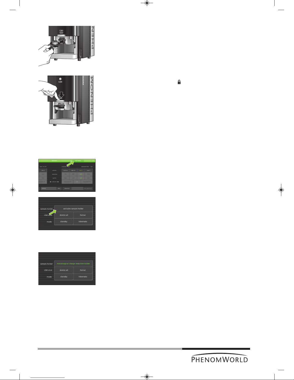
7 Insert the sample holder into the holder slot.
> If the door is not fully open the sample holder will not insert.
The sample holder is inserted correctly when the SAMPLE LED (2) lights up green
and the message ‘Please load sample’ disappears from the Image screen.
8 Close the door by sliding it down firmly (some initial force is required).
> The door will automatically be locked. ‘ ‘ lights up orange.
> The sample is loaded and ready for imaging.
> If the Phenom was in standby or hibernate (power saving) mode, the Phenom will
be now be re-activated. Refer to 4.1 ‘Waking-up the Phenom’.
> The sample automatically moves to the optical imaging position.
> Nosampleholderinserted (fig. 5,11) lights up when you start imaging without a
sample holder inserted. Refer to 4.3.1 ‘Activating the sample holder’.
4.3.1 Activating the sample holder
When a new sample holder is inserted for the first time, the holder needs to be activated.
1 Note the code that is located at the bottom of the sample holder.
2 Touch SETTINGS in the selection bar.
> The Settings screen appears.
3 Insert the sample holder. Refer to 4.3 ‘Loading samples’.
4 Touch activate sample holder.
5 Type in the code, noted in step 1.
If you forgot to note the code in step 1, you can still remove the sample holder from the
holder slot, note the code, reinsert the sample holder and continue with step 5.
6 Touch OK to confirm.
> The sample holder is now activated and its name will be displayed when the holder
is inserted.
PW_Phenom_Pro_X_Pro_Pure_Print:PW_Phenom_G2_Pro_G2_Pure 19-11-13 20:54 Pagina 26

27
Operation
Note!
4.4 Using the touch screen
All Phenom operation is done via the touch screen buttons (fig. 1,13) and the rotary knob
(fig. 1,9). In general all buttons function in the same way.
1 Touch a button (icon) to activate its function.
2 Move the rotary knob to use the function.
If desired, press ? in the screen selection bar. An information balloon will then
appear when a button is touched.
4.5 Optical imaging
> After the Phenom door (fig. 1,4) is closed, the sample is transferred automatically to
the optical imaging position.
> The optical camera is activated and the image is displayed in the main viewing
window (fig. 3,1) of the Image screen.
> The part of the sample that is magnified in the main viewing window is displayed in
the optical overview window (fig. 3,10).
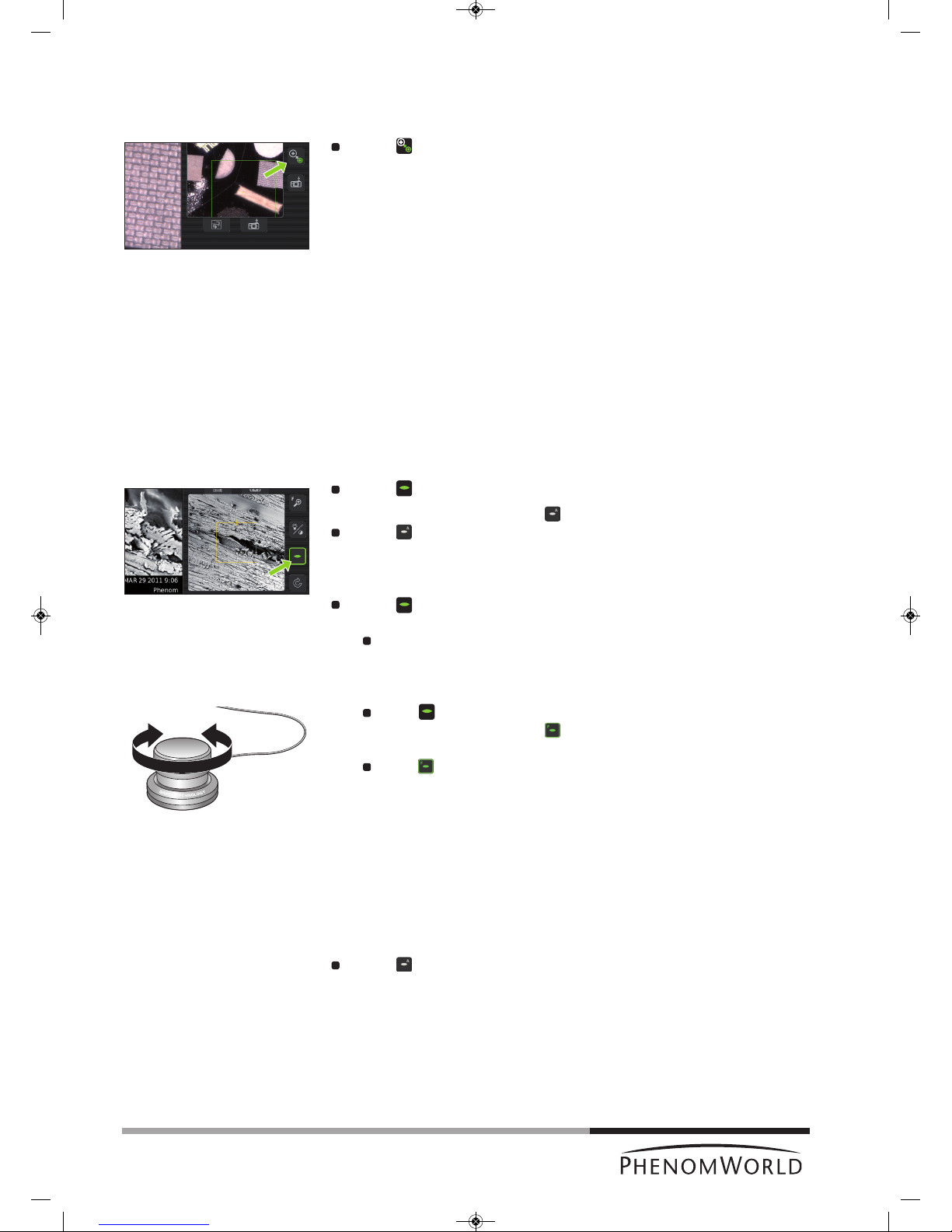
4.5.1 Adjusting focus
Touch (fig. 3,4) to activate focus adjustment.
> A focus slider appears, showing the current focus setting.
Rotate the rotary knob (fig. 1,8) to adjust the focus of the optical image.
> Adjustment is made visible by the slider.
Press (fig. 3,4) or the rotary knob (fig. 1,9) to select fine focus.
> An ‘F’ appears on the button and focus adjustment now takes place in small steps.
Press (fig. 3,4) or the rotary knob (fig. 1,9) again to return to normal (coarse)
focus.
The focus setting at the Navcam position is used to set the initial focus for the SEM
position. A good focus at the Navcam will give a better starting focus and improve the result
of the Auto focus in SEM position.
4.5.2 Adjusting brightness and contrast
Touch (fig. 3,4) to activate brightness adjustment.
> A brightness slider appears, showing the current brightness setting.
Rotate the rotary knob (fig. 1,9) to adjust the brightness of the optical image.
> Adjustment is made visible by the slider.
Touch (fig. 3,4) again to activate contrast adjustment.
> A contrast slider appears, showing the current contrast setting.
Rotate the rotary knob (fig. 1,9) to adjust the overall contrast of the optical image.
> Adjustment is made visible by the slider.
> This adjustment allows the optical image contrast to be changed from direct to
indirect lighting
PW_Phenom_Pro_X_Pro_Pure_Print:PW_Phenom_G2_Pro_G2_Pure 19-11-13 20:54 Pagina 27
28
4.5.3 Adjusting magnification
(ProX / Pro)
Touch (fig. 3,4) to activate the magnification adjustment function.
> A magnification slider appears, showing the current magnification setting.
Rotate the rotary knob (fig. 1,9) to to adjust the magnification of the optical image.
>
The adjustment is made visible by the slider.
4.5.4 Moving the sample
Touch a particular part of the sample on the main viewing window (fig. 3,1).
>
This part will be moved to the center of the field of view.
Touch one of the directional arrows (fig. 3,12).
> The sample moves in the direction of the arrow.
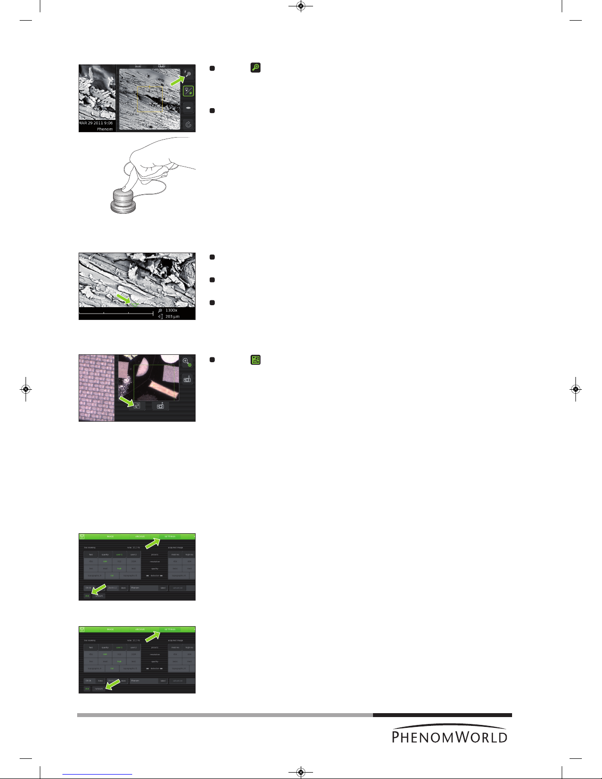
Touch a particular part of the sample on the optical overview window (fig. 3,11).
> This part will be moved to the center of the field of view.
4.5.5 Sample overview
Touch (fig. 3,9).
> The sample holder will now be moved into different positions, each covering a part
of the holder. In each position the image is captured and shown in the optical
overview window (fig. 3,11) to produce an optical overview of the entire holder
content.
4.5.6 Storing images
Images can be be stored on a USB 2.0 flash drive (USB Flash drive) as well as on a
(Windows) network share. For network configuration, refer to 5.7.4 ‘Routine pages’ ‘Network’.
Selecting storage location
When a USB Flash drive is inserted into one of the Phenom USB ports (fig. 1,7 / fig. 2,6), the
USB Flash drive is automatically selected as storage location. To manually select a storage
location:
1 Touch SETTINGS in the screen selection bar.
> The Settings screen appears.
2 Touch USB.
> Images will now be stored on the USB 2.0 flash drive.
OR:
1 Touch SETTINGS in the screen selection bar.
> The Settings screen appears.
2 Touch network.
> The path field appears on the screen, together with a keyboard.
PW_Phenom_Pro_X_Pro_Pure_Print:PW_Phenom_G2_Pro_G2_Pure 19-11-13 20:54 Pagina 28

29
Note
!
3 Enter server name, share path, domain name, user name and password. Enter the
user name and password that you use to get access to Windows on your computer.
For example: ‘//server001/folder/username’. Use forward slashes instead of
backslashes.
– If a USB Flash drive is inserted in the Phenom, the network settings are saved on it.
When you later re-insert this USB Flash drive, the network settings will be filled in
a
utomatically and you will only have to enter your password.
– If the USB Flash drive is removed from the Phenom, the network share is also
disconnected as a security measure.
4 Touch OK to confirm.
> If that fails (because you haven't filled in all fields, or something is wrong), a
message with the details of the problem will be displayed.
> Images will now be stored on the selected network share.
5 Touch Image in the screen selection bar to return to the Image screen.
Storing images
T
ouch (A) to store the image displayed in the main viewing window (fig. 3,1).
Touch (B) to store the image displayed in the optical overview window (fig. 3,11).
Touch (C) to store the image displayed in the electron overview window (fig. 3,3).
Parameters for settings associated with storing images can be selected on the
Settings screen.
> Images will be stored on the selected storage location (USB flash drive or network
share). The storage location will be displayed in the status window.
When storing images on the supplied USB Flash drive (fig. 1,10), make sure the USB Flash
drive is correctly formatted and inserted into one of the Phenom USB ports (fig. 1,7 / fig. 2,6).
The USB Flash drive can be inserted at any time. For formatting the USB Flash drive refer to
5.6.1 ‘USB stick’.
A
C
B
PW_Phenom_Pro_X_Pro_Pure_Print:PW_Phenom_G2_Pro_G2_Pure 19-11-13 20:54 Pagina 29
30
Notes!
4.6 Electron imaging
After the part of the sample you wish to view has been centered in the optical overview
window (fig. 3,10), the sample can be positioned for high resolution (electron) imaging.
Touch (fig. 3,9) to select electron imaging mode.
>The sample will be transferred to electron imaging position.
> A progress bar shows the transfer progress.
> All settings made for optical imaging will be saved for electron imaging.
> When the sample is positioned for electron imaging, an image of the sample is
displayed in the main viewing window (fig. 3,1) of the Image screen. The image is
displayed in the lowest possible magnification (depending on the physical height of
the sample).
> The part of the sample that is magnified in the main viewing window (fig. 3,1) is
displayed in the electron overview window (fig. 3,3). This is indicated by a colored
s
quare. The image is displayed at the lowest magnification factor.
> A colored rectangle or cross (above a certain magnification level) in the optical
overview window (fig. 3,11) also indicates the part of the sample that is magnified in
the main viewing window.
4.6.1 Adjusting focus
Depending on the current status, the focus can be set to automatic or manual control.
Auto focus
Touch (fig. 3,4) for 2 seconds to activate the Auto focus function.
> An ‘A’ appears on the button .
Touch (fig. 3,4) again to start Auto focus adjustment.
> The focus will now be adjusted automatically.
Manual focus
Touch (fig. 3,4) to activate the focus function.
> A focus slider appears, showing the current focus setting.
Rotate the rotary knob (fig. 1,8) to adjust the focus of the optical image.
> Adjustment is made visible by the slider.
Fine focus
Touch (fig. 3,4) or the rotary knob (fig. 1,8) to select fine focus.
> An ‘F’ appears on the button and focus adjustment now takes place in small
steps.
Touch (fig. 3,4) or the rotary knob (fig. 1,8) again to return to normal (coarse)
focus.
– Auto focus works best when high contrast features are present in the center of the
image screen.
– If auto focus does not produce the desired result, use manual focus.
– Manual focus takes place in steps that are proportional to the current magnification
setting. The higher the magnification setting, the more sensitive the rotary knob will
become.
Touch (fig. 3,4) again for 2 seconds, to return to manual mode.
PW_Phenom_Pro_X_Pro_Pure_Print:PW_Phenom_G2_Pro_G2_Pure 19-11-13 20:54 Pagina 30

31
4.6.2 Adjusting brightness and contrast
Touch (fig. 3,4) to activate brightness adjustment.
> A brightness slider appears, showing the current brightness setting.
Rotate the rotary knob (fig. 1,9) to adjust the brightness of the electron image.
> Adjustment is made visible by the slider.
Touch (fig. 3,4) again to activate contrast adjustment.
> A contrast slider appears, showing the current contrast setting.
Rotate the rotary knob (fig. 1,9) to adjust the overall contrast of the electron
image.
> Adjustment is made visible by the slider
Auto contrast / brightness
Touch (fig. 3,4) for 2 seconds to activate the
Auto contrast / brightness function.
> An ‘A’ appears on the button.
T
ouch (fig. 3,4) again to start
A
uto contrast / brightnessadjustment.
> Brightness and contrast will now be adjusted automatically.
Touch (fig. 3,4) again for 2 seconds, to return to manual mode.
4.6.3 Magnifying the image
Touch (fig. 3,4) to activate the magnification function.
> A magnification slider appears, showing the current magnification factor.
The magnification factor is also shown on the data bar (fig. 3,2) if activated on the
Settings screen.
Rotate the rotary knob (fig. 1,9) to magnify the image to the desired size.
>
The magnification factor is made visible by the slider and on the data bar (fig. 3,2).
Touch (fig. 3,4) or the rotary knob (fig. 1,9) to select fine magnification.
> An ‘F’ appears on the button and magnification now takes place in small steps.
Touch (fig. 3,4) or the rotary knob (fig. 1,9) again to return to normal (coarse)
magnification.
4.6.4 Rotating the image
Touch (fig. 3,4) to activate the rotation function.
Rotate the rotary knob (fig. 1,9) to rotate the image in the desired direction.
Press (fig. 3,4) or the rotary knob (fig. 1,9) to select fine rotation.
> An ‘F’ appears on the button and rotation now takes place in small steps.
Press (fig. 3,4) or the rotary knob (fig. 1,9) again to return to normal (coarse)
rotation.
Press (fig. 3,4)
for 2 seconds to deactivate the rotation function and show the
image again in un-rotated state.
PW_Phenom_Pro_X_Pro_Pure_Print:PW_Phenom_G2_Pro_G2_Pure 19-11-13 20:54 Pagina 31

32
4.6.5 Moving the sample
Touch a particular part of the sample on the main viewing window (fig. 3,1).
>
This part will be moved to the center of the field of view.
Touch one of the directional arrows (fig. 3,12).
> The sample moves in the direction of the arrow.
Touch a particular part of the sample on the electron overview window (fig. 3,3).
> This part will be moved to the center of the field of view.
If a sample has been moved outside of the original field of view, the electron overview
window (fig. 3,3) turns black.
Touch (fig. 3,6) to refresh the electron overview window (fig. 3,1).
4.6.6 Storing images
I
mages can be be stored on a USB 2.0 flash drive (USB Flash drive) as well as on a
(Windows) network share. For network configuration, refer to 5.7.4 ‘Routine pages’ -
‘Network’.
Selecting storage location
When a USB Flash drive is inserted into one of the Phenom USB ports (
fig. 1,7 / fig. 2,6
), the
USB Flash drive is automatically selected as storage location. To manually select a storage
location:
1 Touch SETTINGS in the screen selection bar.
> The Settings screen appears.
2 Touch USB.
> Images can now be stored on the USB 2.0 flash drive.
3 Touch Image in the screen selection bar to return to the Image screen.
OR:
1 Touch SETTINGS in the screen selection bar.
> The Settings screen appears.
2 Touch network.
> The path field appears on the screen, together with a keyboard.
3 Enter server name, share path, domain name, user name and password. Enter the
user name and password that you use to get access to Windows on your computer.
4 Confirm by pressing OK.
> If that fails (because you haven't filled in all fields, or something is wrong), a
message with the details of the problem will be displayed.
> Images can now be stored on the selected network share.
5 Touch IMAGE in the screen selection bar to return to the Image screen.
PW_Phenom_Pro_X_Pro_Pure_Print:PW_Phenom_G2_Pro_G2_Pure 19-11-13 20:54 Pagina 32
33
Note!
Note!
Storing images
Touch (A) to store the image displayed in the main viewing window (fig. 3,1).
Touch (B) to store the image displayed in the optical overview window (fig. 3,11).
Touch (C) to store the image displayed in the electron overview window (fig. 3,3).
Parameters for settings associated with storing images can be selected on the
Settings screen.
>
Images will be stored on the selected storage location (USB flash drive or network
share). The storage location will be displayed in the status window.
When storing images on the supplied USB Flash drive (fig. 1,10), make sure the USB Flash
drive is correctly formatted and inserted into one of the Phenom USB ports (
fig. 1,7 / fig. 2,6
).
The USB Flash drive can be inserted at any time. For formatting the USB Flash drive refer
to 5.6.1 ‘USB Flash drive’.
4.7 Viewing stored images
Images stored on the USB Flash drive or on a (Windows) network share can be viewed on
the Archive screen. When the Archive screen is entered, it shows the images stored on the
currently selected storage location. For selecting the desired storage location and
configuring the network share, refer to chapters 4.5.5 ‘Sample overview’ and 4.6.6 ‘Storing
images’.
When viewing images stored on the supplied USB Flash drive (fig. 1,10), make sure the
USB Flash drive is correctly formatted and inserted into one of the Phenom USB ports
(
fig. 1,7 / fig. 2,6
). The USB Flash drive can be inserted at any time. For formatting the USB
Flash drive refer to 5.6.1 ‘USB Flash drive’.
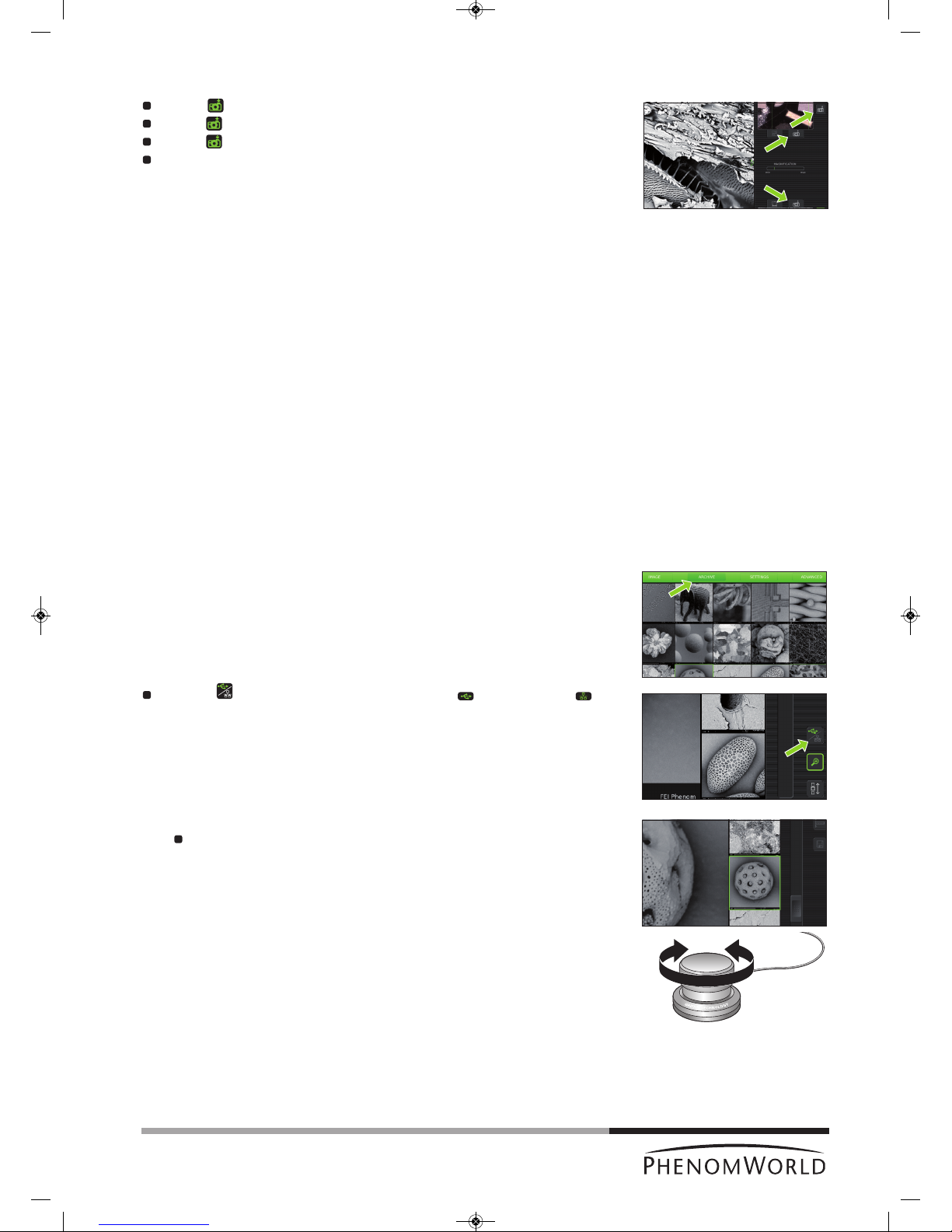
1 Touch ARCHIVE in the screen selection bar.
> The Archive screen appears.
>
The images stored on the current location are shown on the main viewing window
(fig. 4,1).
Use the button (fig. 4,5) to select USB Flash drive ()or network share ( ).
This is only possible when both storage locations are available.
2 Use the rotary knob (fig. 1,9) to scroll through your stored images.
The selected (highlighted) image can be displayed at full size on the main viewing
window by pressing the rotary knob (fig. 1,9) or touching the thumbnail image.
> The other images are then shown in thumbnail format in the thumbnail gallery
(fig. 4,3).
A
C
B
PW_Phenom_Pro_X_Pro_Pure_Print:PW_Phenom_G2_Pro_G2_Pure 19-11-13 20:54 Pagina 33

34
When the image is displayed at full size, digital zoom is available by touching
(
fig. 4,5).
The image can then be magnified digitally using the rotary knob (fig. 1,9).
3 Touch (fig. 4,5) to continue scrolling through your images.
4.7.1 Comparing images
(ProX / Pro)
1 Touch (fig. 4,5) to select the image in the main viewing window as the first image
for comparison.
2 Use the rotary knob (fig. 1,9) or the scroll bar (fig. 4,4) to select the second image you
wish to compare to the image in the main viewing window.
3 Press the rotary knob (fig. 1,9) to switch between the 2 selected images for
comparison.
Touch (fig. 4,5) to continue scrolling through your pictures.
4.7.2 Deleting stored images
1 Use the button (fig. 4,5) to select the storage location (USB Flash drive, or
network share, ).
2 Use the rotary knob (fig. 1,9) or the scroll bar (fig. 4,4) to select the image you wish to
delete.
3 Touch (fig. 4,5) to delete the image.
To delete all images touch ‘4’ to confirm or ‘8’ to cancel. Refer to 5.6.1 ‘USB
Flash drive’ / 5.6.2 ‘Mode’’.
For deleting all images stored on the USB Flasdrive, refer to 5.6.1 ‘USB Flashdrive’.
PW_Phenom_Pro_X_Pro_Pure_Print:PW_Phenom_G2_Pro_G2_Pure 19-11-13 20:55 Pagina 34
35
4.8 Measuring on stored images
(
ProX / Pro)
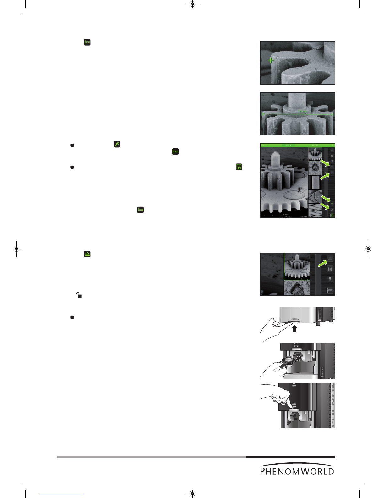
1 Touch (fig. 4,5) to activate the measurement function.
2 Touch the desired starting point at the displayed image.
> The starting point is indicated with a ‘+’.
3 Touch the desired ending point at the displayed image.
> The distance between starting point and ending point is displayed in microns (µm).
If desired, touch (fig. 4,5) to digitally magnify the image (digital zoom) so you
can fine-tune starting and ending point. Use (fig. 4,5) to toggle between
starting and ending point.
If you wish to store a copy of the image with the measurement data, touch
(fig. 4,5) to store the image.
> A copy of the image with the measurement data 'burned in' will be stored at the
selected (storage) location.
> The copy contains colour information so the file size will be bigger than the
original.
>
If the measurement button cannot be selected the image is not suited for
measurement, for example because it was stored as BMP or not made on the
Phenom.
4.9 Unloading the sample
1 Touch (fig. 4,5) to eject the sample and allow the door to be opened.
> ‘Unload: are you sure?’ appears on the screen.
2 Touch ‘4’ to confirm or ‘8’ to cancel.
> After confirmation the sample holder will be brought to the unload position.
> ‘ ’ (3) lights up green, indicating that the door (4) can be opened.
3 Open the door (fig. 1,4) by pushing the handle upward.
Hold the handle and raise the door to its fullest extent.
4 Remove the sample holder and close the door (fig. 1,4) by sliding it down (some initial
force is required).
PW_Phenom_Pro_X_Pro_Pure_Print:PW_Phenom_G2_Pro_G2_Pure 19-11-13 20:55 Pagina 35
36
Note!
Note!
4.10 Switching off the Phenom electron
source
4.10.1 Switching off the Phenom
The Phenom can be switched off in several ways:
Standby
In standby mode the electron source will be switched off in order to increase lifetime.
Press
y (fig. 1,1) on the Phenom.
> The POWER LED (fig. 1,1) lights up orange. The Phenom is now in standby mode.
OR:
1 Touch SETTINGS in the selection bar.
> The Settings screen appears.
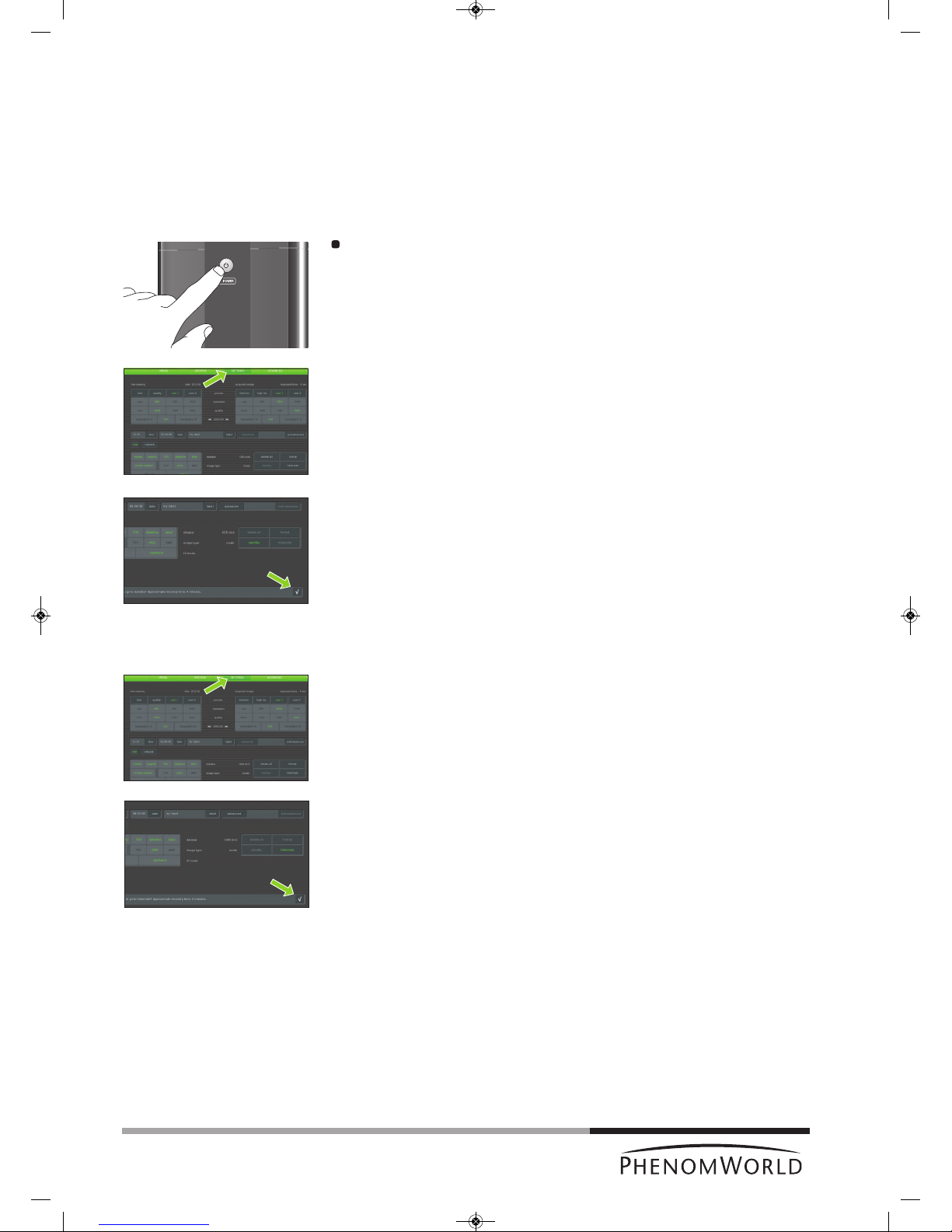
2
Touch standby.
> ‘Do you want to go to standby? Approximate recovery time: 4 minutes.’ appears on
the screen.
3 Touch ‘4’ to confirm or ‘8’ to cancel.
> The POWER LED (fig. 1,1) lights up orange. The Phenom is now in standby mode.
If the Phenom is not used for one hour, it automatically enters standby mode.
Hibernate (Power saving mode)
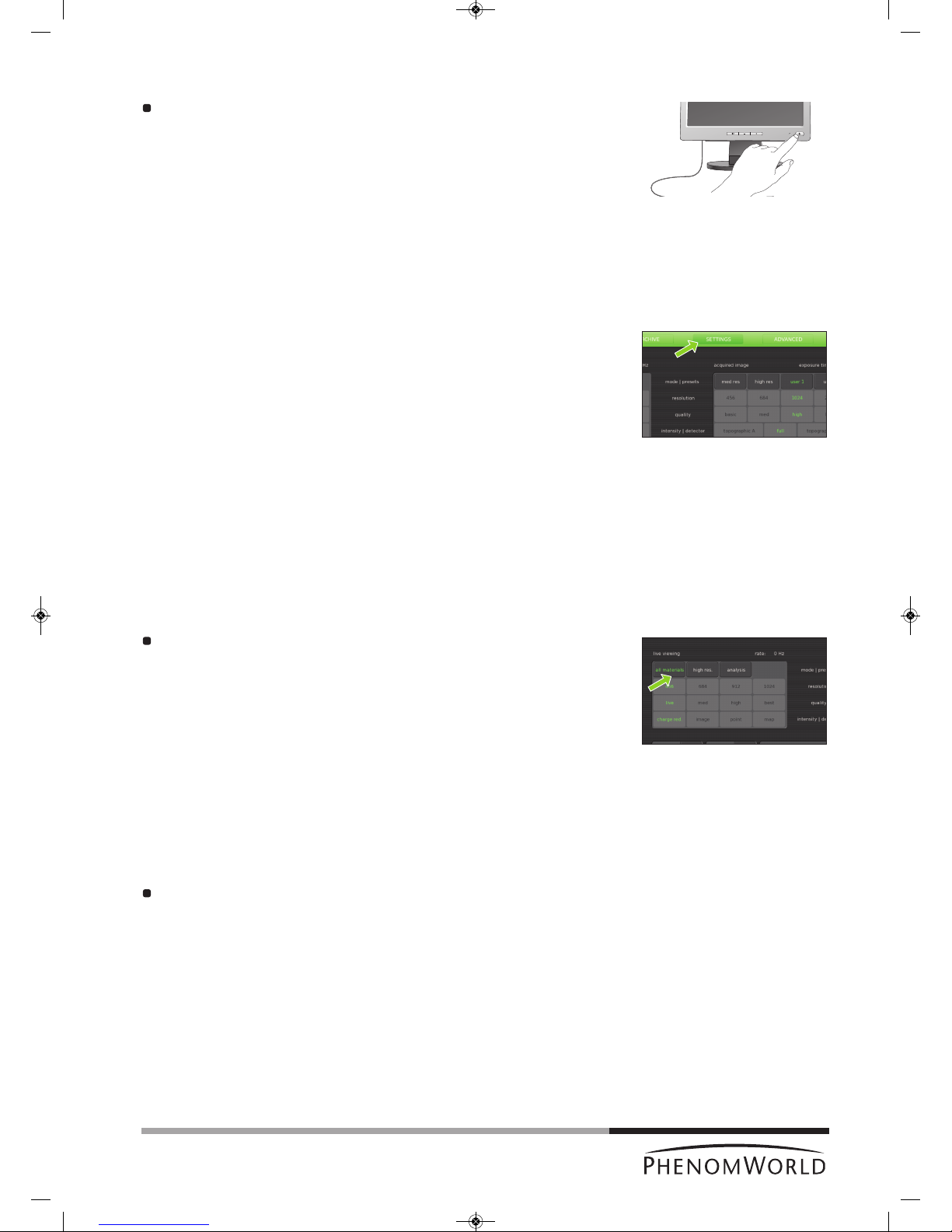
1 Touch SETTINGS in the selection bar.
> The Settings screen appears.
2 Touch hibernate.
> ‘Do you want to go to hibernate? Approximate recovery time: 6 minutes.’ appears
on the screen.
3 Touch ‘4’ to confirm or ‘8’ to cancel.
> The POWER LED (fig. 1,1) lights up orange. The Phenom is now in power saving
(hibernate) mode.
If the Phenom is not used for 72 hours, it automatically enters hibernate mode.
PW_Phenom_Pro_X_Pro_Pure_Print:PW_Phenom_G2_Pro_G2_Pure 19-11-13 20:55 Pagina 36
37
4.10.2 Switching off the flat panel touch screen monitor
Press y(fig. 1,1) on the monitor.
> The power LED (fig. 1,1) goes out. The monitor is now switched off.
4
.10.3 Switching off the system completely
Only use this option if you have to transport the Phenom or if the Phenom or the
pre-vacuum pump requires repair.
For switching off the system completely, refer to 5.7.2 ‘Shutdown’.
5. Phenom settings
All Phenom settings are made on the Settings screen. The Settings screen can be
accessed by touching SETTINGS in the selection bar.
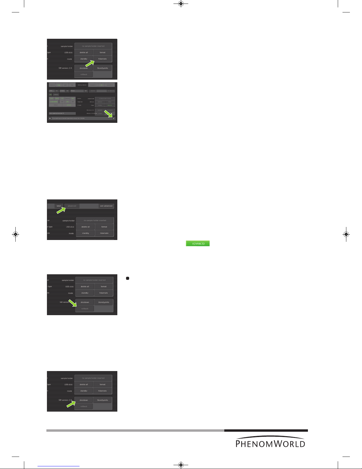
5.1 Live viewing settings
Here you can adjust and store viewing conditions for electron imaging.
5.1.1 Mode
All materials - selects the lowest acceleration voltage (5kV) with less beam penetration
which can be used to image all different type of materials.
High res. - selects medium acceleration voltage (10kV) which can be used for high
resolution imaging on hard materials.
Analysis - Selects high acceleration voltage (15Kv) for large beam penetration
typically used for EDS analysis.
Touch the button with the desired mode.
5.1.2 Resolution
Here you can select the desired pixel resolution. Pixel resolution is the number of pixels in
the image.
456 - 456 x 456 pixel resolution.
684 - 684 x 684 pixel resolution.
912 - 1024 x 1024 pixel resolution.
1024 - 2048 x 2048 pixel resolution.
Touch the button with the desired pixel resolution.
PW_Phenom_Pro_X_Pro_Pure_Print:PW_Phenom_G2_Pro_G2_Pure 19-11-13 20:55 Pagina 37

38
5.1.3 Quality
Here you can select the desired response speed, picture quality and noise level.
L
ive - highly responsive but noisy.
Med(ium) - quickly responding with medium noise level.
High - high quality but medium responsive.
Best - ‘picture’ quality but slowly responding.
Touch the live, med, high or best button to select the desired response speed,
noise level and picture quality.
5.1.4 Intensity
Charge red. - selects the lowest beam current/spot size to minimize charging effects on a
non conductive sample and for high resolution imaging.
Image - selects medium beam current/spot size for ‘most common’ imaging.
Point - selects a high beam current which is used for EDS analysis.
M
ap - selects maximum beam current which is used for EDS analysis.
Touch the button with the desired intensity.
5.2 Acquired image settings
Here you can adjust and store the conditions for stored images.
5.2.1 Backscatter detector mode
The Phenom detector is a 4-segmented detector that can operate in 2 modes:
Full
Image contrast is mainly due to changes in the sample composition.
Topographic
Image contrast is mainly due to the sample topography. The signal strength in this mode is
lower than in full mode so adjustment of contrast and brightness will be necessary.
To compensate for differences in signal strength, an auto contrast/brightness routine will be
performed automatically when switching to a different detector mode.
Topographic mode has two settings: Topographic A which accentuates topgraphy
orientated in the X direction and Topographic B which accentuates topography orientated
in the Y direction.
Touch the topographic A, full or topographic B button to select the desired detector
mode.
PW_Phenom_Pro_X_Pro_Pure_Print:PW_Phenom_G2_Pro_G2_Pure 19-11-13 20:55 Pagina 38

39
5.2.2 Quality
Here you can select the desired acquisition speed, picture quality, noise level and exposure
t
ime for image acquisition.
The exposure time is indicated above the acquired image frame
(e. g. exposure time: 0.9 sec).
Basic - quick but noisy image acquisition.
Med(ium) - fast acquisition with medium noise level.
High - high quality acquisition through medium exposure time.
Best - picture quality acquisition with long exposure time.
Touch the basic, med, high or best button to select the desired acquisation speed,
exposure time, picture quality and noise level.
5.2.3 Resolution
For acquired image mode, pixel resolution settings are similar to those available for live
v
iewing mode. The higher the resolution, the higher the exposure time.
Select the desired setting by touching the appropriate button (456, 684, 1024 or
2048).
5.2.4 Presets
Default settings for acquisition speed, noise level, pixel resolution, picture quality and
exposure time are stored under the med res and high res buttons.
Defaults under the med res button are med and 684, meaning fast acquisition with medium
noise level and a pixel resolution of 684 x 684 and a high exposure time.
Defaults under the high res button are high and 1024, meaning high quality acquisition,
medium exposure time and a pixel resolution of 1024 x 1024.
Activate the desired settings by touching the appropriate button. (fast or quality).
PW_Phenom_Pro_X_Pro_Pure_Print:PW_Phenom_G2_Pro_G2_Pure 19-11-13 20:55 Pagina 39

40
5.2.5 Storing user settings
As for live viewing settings, two sets of user settings can be stored for acquired image
s
ettings.
Touch user 1 and select the desired quality and resolution settings (refer to 5.1.2
‘Quality’ and to 5.1.3 ‘Resolution’).
> The settings will be stored under the user1 button.
If desired, a second set of settings can be stored in the same way under user 2.
When in acquired image mode, press user 1 or user 2 to select the settings stored
under the button.
5.3 Date and time
Here you can adjust date (dd-mm-yy format) and time (24 hours format).
5.3.1 Adjusting the date
1 Touch the date button.
>
A keyboard appears on the screen.
2 Enter the correct date.
> The date will be displayed on the screen and on the databar if the datetime function
is enabled. For this refer 5.4.1 ‘Databar’.
3 Touch OK to store the date or CANCEL to quit date adjustment.
5.3.2 Adjusting the time
1 Touch the time button.
> A keyboard appears on the screen.
2 Enter the correct time.
> The time will be displayed on the screen and on the databar if the datetime function
is enabled. For this refer 5.4.1 ‘Databar’.
3 Touch OK to store the time or CANCEL to quit time adjustment.
5.4 Databar / Image type / UI mode
5.4.1 Databar
Here you can select the items that will be displayed on the databar when operating the
Phenom. You can also set the databar to be included in your stored images. The following
items can be displayed on the databar:
marker - µm marker. Shows current active ruler size. E.g. 10 µm.
magnify - shows magnification factor. E.g. 1000 x.
FOV (Field Of View) - shows total picture size. E.g. 10 µm.
datetime - shows date and time.
label - shows sample name
Select the items to be shown on the databar by touching the appropriate buttons
(marker, magnify, FOV, datetime, label).
Touch include databar if you wish the databar to be included in your stored images.
5.4.2 Image type
Here you can select the format you wish to store your images in.
TIFF - Lossless compression, larger file sizes.
JPEG - Lossy compression but smaller file sizes.
BMP - Windows bitmap format; no compression; large files and no measurement data
included.
Select the desired file format by touching the appropriate button (TIFF, JPEG or BMP).
PW_Phenom_Pro_X_Pro_Pure_Print:PW_Phenom_G2_Pro_G2_Pure 19-11-13 20:55 Pagina 40

41
Notes!
5.4.3 UI mode
Here you can select the desired User Interface mode. You can select whether the button
b
ar on the Image screen will be placed on the left or on the right side of the screen.
Select the desired position by touching the lefthand button or the righthand button.
5.5 Label
Here you can enter a sample / file name.
1 Touch the label button.
> A keyboard appears on the screen.
2 Enter a sample name with a maximum of 15 characters.
> The image will be saved with the name created and a numerical file extension will
be added to subsequent images taken.
To erase the name, use the backspace button.
>
The name will be displayed left of the button and on the databar if the label function
is enabled. For this refer 5.4.1 ‘Databar’.
3 Touch OK to store the sample name or CANCEL to quit labeling.
5.6 USB stick / Mode
5.6.1 USB stick
Touch the delete all button if you wish to delete all images on the USB Flash drive.
Touch the format button if you wish to format the USB Flash drive.
5.6.2 Mode
To save the electron source and to reduce power consumption, the Phenom can be put into
standby or hibernate mode.
Standby
1 Touch the standby button to put the Phenom into standby mode.
> ‘Do you want to go to standby? Approximate recovery time: 4 minutes.’ appears on
the screen.
2 Touch ‘4’ to confirm or ‘8’ to cancel.
> The POWERLED (fig. 1,1) lights up orange. The Phenom is now in standby mode.
– If the Phenom is not used for one hour, it automatically enters standby mode.
– You can also press
y (fig. 1,1) on the Phenom to put the Phenom in standby mode.
PW_Phenom_Pro_X_Pro_Pure_Print:PW_Phenom_G2_Pro_G2_Pure 19-11-13 20:55 Pagina 41
42
Note!
Notes
!
Hibernate (Power saving mode)
1 Touch hibernate.
> ‘Do you want to go to hibernate? Approximate recovery time: 6 minutes.’ appears
on the screen.
2 Touch ‘4’ to confirm or ‘8’ to cancel.
> The POWERLED (fig. 1,1) lights up orange. The Phenom is now in power saving
(hibernate) mode.
If the Phenom is not used for 72 hours, it automatically enters hibernate mode.
5.7 Advanced settings
P
roperly adjusted advanced settings highly determine the overall viewing quality of the
Phenom and are therefore to be done by experienced users only. To avoid improper
adjustment of the settings as well as accidental shutdown of the Phenom, these settings are
password protected. Contact the tool owner for the password.
To access the advanced settings:
1 Touch the advanced button
> A keyboard appears on the screen.
2 Enter the log-in PASSWORD (tool owner has received this password from Phenom-
World), confirm with OK.
> The SWversion/Previous/Rollback/Shutdown / StoreSysInfo frame appears
on the screen and the button appears in the screen selection bar.
5.7.1 SW (software) version
SW version shows the current Phenom software version. If you wish to revert to the
previous software version:
Touch rollback.
> The Phenom now reboots with the previous software version.
– Only use the rollback option in case you encounter problems while upgrading the
Phenom software or if you are unable to operate the Phenom when new software is
uploaded.
– Information regarding software upgrades will be provided by Customer Support.
5.7.2 Shutdown
Only use this option if you have to transport or move the Phenom.
1 Touch Shutdown to prepare the Phenom for complete switch off.
> The Phenom now starts preparing for complete switch off. This will take
approximately 35 minutes when the Phenom is in operation mode and
approximately 5 minutes when the Phenom is in hybernate mode. A countdown
timer shows the remaining time until shutdown.
> After approximately 5 / 35 minutes the message ‘It’s now safe to turn off your
system’ appears.
2 Set the 0 / I switch (fig. 1,14) on the power supply to 0.
PW_Phenom_Pro_X_Pro_Pure_Print:PW_Phenom_G2_Pro_G2_Pure 19-11-13 20:55 Pagina 42

43
Notes!
5.7.3 StoreSys(tem)Info
If a problem occurs you can touch StoreSysInfo to store a file with the current system
i
nformation on the USB Flash drive (fig. 1,10).
> The file will be named SysInfo_<MachineID>_yyyy-mm-dd_hh-mm-ss.xml.gz
and can be found in the feico folder on the USB Flash drive.
The system information file can be sent to the Phenom help desk:
support@phenom-world.com
5.7.4 Routine pages
In the Source Tilt and Stigmate pages you can optimize and store viewing conditions for
electron imaging. In the Network and Connectivity pages you can configure your network
settings and configure and activate the Phenom Remote Assistant, in the Service page
you can select a different screen type.
– You can navigate throught the Routine pages, using the < and > buttons in the top-
right corner of the screen. With > you select the next Routine page; with < you go
back to the previous Routine page.
– For setting the working distance and loading the sample, refer to 4.3’ Loading
s
amples’; for unloading the sample, refer to 4.9 ‘Unloading the sample’.
5.7.4.1 Source Tilt
Here you can align the Phenom electron beam (optimize the illumination intensity).
Alignment has to be made in electron imaging mode. When in optical imaging mode, first
select electron imaging mode by touching (fig. 3,10) or press the Manual button on the
Source Tilt screen that appears after pressing .
Touch the button in the selection bar.
> The SourceTilt screen appears.
Auto alignment
When using the Auto alignment function, the sample surface should be homogeneous and
not contain large contrast differences.
1 Touch Auto to start an automatic Source Tilt alignment.
> The Phenom electron beam will now automatically be aligned. This usually takes a
few seconds but in some situations may take several minutes.
> Adjustments made on the X and Y axis are visible on the screen.
When automatic Source Tilt alignment is finished, you can fine-tune the adjustment
manually, using the rotary knob as described in ‘Manual alignment’, hereafter.
2 Touch
’ ’ to save the adjustment or ‘8’ to reset the previous settings and quit
Source Tilt setting.
3 When finished, touch > to select the next Routine page (Stigmate).
PW_Phenom_Pro_X_Pro_Pure_Print:PW_Phenom_G2_Pro_G2_Pure 19-11-13 20:55 Pagina 43

44
Manual alignment
1 Touch Manual.
2 Select TILT X or TILT Y and follow the on-screen instructions for electron beam
alignment.
3 Use the rotary knob (8) to make the adjustment for TILT X and TILT Y.
>
Adjustments made on the X and Y axis are visible on the screen.
4 Touch
’ ’ to save the adjustment or ’8‘ to reset the previous settings and quit
Source Tilt setting.
5.7.4.2 Stigmate
Here you can adjust the roundness of the electron beam, so that image focus is identical in
X and Y directions.
1 In the Source Tilt screen, touch > to access the Stigmate screen.
> The Stigmate screen appears.
2 Select STIG X or STIG Y and follow the on-screen instructions for sharpness
adjustment.
Use the rotary knob (fig. 1,8) to obtain the sharpest image for STIG X and STIG Y.
> Adjustments made on the X and Y axis are visible on the screen.
3 Touch
’ ’ to save the adjustments or ‘8’ to cancel and quit Stigmate setting.
PW_Phenom_Pro_X_Pro_Pure_Print:PW_Phenom_G2_Pro_G2_Pure 19-11-13 20:55 Pagina 44
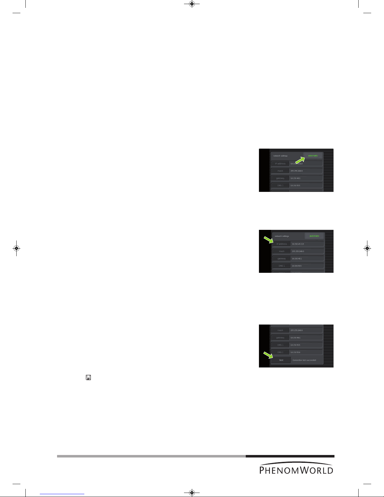
45
Tip!
5.7.4.3 Network
If the Phenom is connected to your Local Area Network, you can store images on a Windows
n
etwork share (refer to 4.5.5 and 4.6.6 ‘Storing Images’). A functioning network connection
with access to the Internet is also required for the Phenom Remote Assistant (refer to
‘Phenom Remote Assistant settings’ under 5.7.4.4 ‘Connectivity’).
Network configuration
1 Check if the ethernet cable is properly connected between the Phenom Ethernet
connector (fig. 2,3) and your LAN (Local Area Network).
For connection, refer to 3. ‘Installing the Phenom’ - ‘Connections’.
> In most corporate networks, connected systems are automatically configured using
DHCP (Dynamic Host Configuration Protocol). If the Phenom detects a DHCP
server in your network, the message ‘Status: DHCP server detected’ is displayed in
the Statusarea (bottom left of the screen).
> If no DHCP server is detected, the Statusarea will remain empty.
2 If a DHCP server is detected, touch the automatic button in the network settings
pane.
>
automatic lights up green on the button. The DHCP server will now automatically
configure the Phenom network settings.
> During configuration you will see data automatically being entered for all settings.
When all network settings have been configured, continue from step 8.
If no DHCP server is detected (check Status area), the automatic button lights up
grey and the five network settings areas will be enabled. Manual configuration of the
Phenom network settings is now possible. Continue with step 3.
3 Touch the IP address button.
> A keyboard appears.
4 Enter the Phenom IP address, confirm by touching the OK button on the keyboard
and select the next setting by touching the appropriate button (mask).
5 Enter in the data for the other settings (mask, gateway, DNS 1 and DNS 2) in the
same way. Confirm each setting with the OK button on the keyboard and select the
next setting by touching the appropriate button.
You can copy the values for these settings from a Windows system in your network,
or contact your local network administrator.
6 After entering the data for all settings, touch the test button to test the connection.
> The Phenom will now try to contact your gateway system.
> If all settings have been properly made and connection is established, the message
‘Connection test succeeded’ is displayed next to the test button.
> If the message ‘Connection test failed’ is displayed, check if the correct data have
been entered for all settings or contact your network administrator.
7 Touch
’ ’ to save your settings.
> The message ‘Network configuration settings correctly saved’ appears in the Status
area.
> From now on you can store images on a Windows network share.
> All settings will be stored in the Phenom memory even after rebooting the Phenom
software. The network connection will be automatically restored after reboot or
shutdown of the Phenom.
PW_Phenom_Pro_X_Pro_Pure_Print:PW_Phenom_G2_Pro_G2_Pure 19-11-13 20:55 Pagina 45
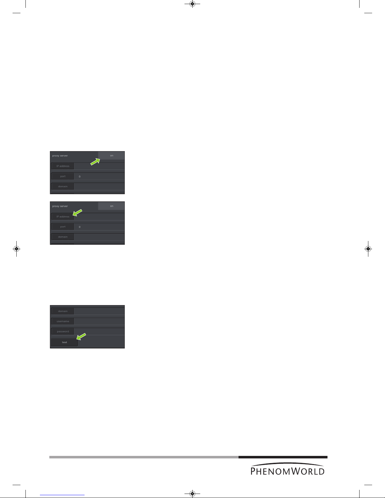
46
Tip!
5.7.4.4 Connectivity
When the Phenom is connected to the Internet, Phenom Remote Assistant (PRA) is
a
vailable. The Phenom can periodically upload technical performance data which is
monitored by Phenom-World’s Customer Support. In this way, maintenance requirement for
the Phenom is more predictable and a better uptime (the time the Phenom is ‘up’ and
running) is achieved. PRA also enables you to request remote assistance by Phenom-World
service engineers. They are then able to operate your Phenom remotely, similar to the
‘remote desktop’ function in Windows, and work with you to resolve any issues with your
Phenom. For more information, refer to the PRA Operations Guide or contact
Phenom-World’s Customer Support.
Proxy server settings
Most corporate networks require Internet connections to go via a proxy server. If this is the
case on your network, set up the proxy server settings in the Connectivity Routine page.
Contact your local network administrator for the required settings.
1 Touch the on button in the proxy server pane to enable the use of a proxy server.
> onlights up green on the button.
2 Touch the IP address button.
> A keyboard appears.
3 Enter the IP address of your proxy server, confirm by touching the OK button on the
keyboard and select the next setting by touching the appropriate button (port).
4 Enter the data for the other settings (port, domain, username, and password) in the
same way. Confirm each setting with the OK button on the keyboard and select the
next setting by touching the appropriate button.
The username and password can be taken from any valid user on your network who has
sufficient permissions to access the Internet. The Phenom does not require an account of
its own.
5 After entering all settings, touch the test button to test the connection.
> The Phenom will now try to establish a connection with the PRA server.
> If all settings have been properly made and a connection can be established, the
message ‘Connection test succeeded’ is displayed in the Statusarea.
> If the message ‘Connection test failed’ is displayed, check if the correct data have
been entered for all settings or contact your network administrator.
A successful connection requires the correct PRA password to be filled in. For this,
refer to ‘Phenom Remote Assistant settings’, hereafter.
PW_Phenom_Pro_X_Pro_Pure_Print:PW_Phenom_G2_Pro_G2_Pure 19-11-13 20:55 Pagina 46
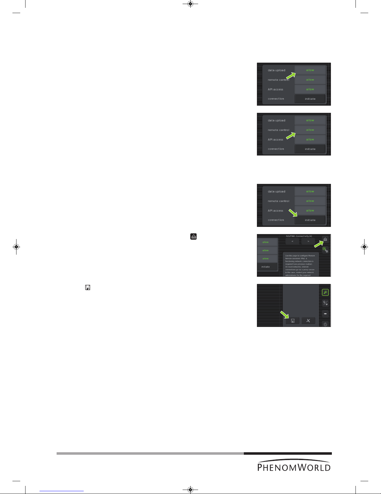
47
Note!
Phenom Remote Assistant settings
The Phenom gives you fine-grained control over the Phenom Remote Assistant settings
and offers industry-standard security. For a detailed description of the technical
performance data and security, refer to your PRA Operations Guide.
1 Touch the allow button next to data upload to allow daily upload of technical
performance data for remote system health monitoring.
> allowlights up green on the button.
2 Touch the allow button next to remote control to allow remote control of the
Phenom.
> allowlights up green on the button.
A remote control connection is onlymade when you explicitly initiate it yourself. To do so,
continue with step 3.
3 Touch the initiate button next to connection to initiate a remote control connection.
Refer to the PRA Operations Guide for instructions on how to set up a remote control
session with a Phenom-World service engineer.
4 The connection can be ended at any time by touching the button next to the
Connectivity label.
> After a remote control session, connection will be ended automatically within
5 minutes.
5 Touch
’ ’ to save your settings.
> The message ‘Connectivity configuration settings correctly saved’ appears in the
Statusarea.
> When data upload is allowed in step 1, the technical performance of the Phenom
will be monitored by Phenom World’s Customer Support and you will be notified if
maintenance is required.
> All settings will be stored in the Phenom memory even after rebooting the Phenom
software. The network connection will be automatically restored after reboot or
shutdown of the Phenom.
PW_Phenom_Pro_X_Pro_Pure_Print:PW_Phenom_G2_Pro_G2_Pure 19-11-13 20:55 Pagina 47

48
Warning!
Cleaning the touch
screen
Cleaning the
microscope
Cleaning the sample
holder
Microscope
environment
6. Maintenance
Do not attempt to remove the microscope cover as this will expose electrical and
mechanical hazards.
Removing the cover will void all warranties.
The Phenom microscope is designed to be low maintenance. Scheduled PM (Planned
M
aintenance) is required to ensure optimum system performance. If problems with
operation do arise, owners can contact Phenom-World’s Customer Support:
- address: Dillenburgstraat 9E
5652 AM Eindhoven
The Netherlands
- e-mail: service@phenom-world.com
- phone: +31 (0)40 259 73 72
- fax: +31 (0)40 259 73 71
- opening hours: Monday - Friday, 09:00 - 17:00 (CET)
More information can also be found on our website: www.phenom-world.com.
As required, the touch screen should be cleaned with a commercially available flat
panel display cleaner.
The screen should only be cleaned when the monitor power is off.
As required the cover surface can be cleaned with a damp cloth.
The floor of the specimen loading area should be kept dust free by wiping with a dust
free dry cloth.
The sample holder and rubber seal should be kept clean of dust by wiping with a dry
cloth or blowing with a commercially available cleaner such as a dust-off can.
The sample holder should be kept free of stains by wiping with a damp cloth as
necessary.
It is recommend to degrease the holder periodically by cleaning it with isopropyl
alcohol applied to a cloth.
Make sure that the table / desk the microscope is placed on is kept clean and dust
free.
The Phenom is equipped with ventilators that force air into the tool. An overload of
dust could be harmful to the microscope.
PW_Phenom_Pro_X_Pro_Pure_Print:PW_Phenom_G2_Pro_G2_Pure 19-11-13 20:55 Pagina 48

49
Note!
Warning!
Symptom
When touching the buttons
o
n the screen, the system
behaves as if touching a
different location.
Buttons on the touch screen
do not respond.
Data bar (fig.3(2)) on Image
screen (fig.3) does not
contain the information I
need.
Image resolution is poor at
high magnification.
Image is fuzzy and cannot be
brought into focus.
No contrast information
( ).
Sample does not
automatically move from
load position to the NavCam
when the door is closed.
The Phenom does not accept
my code.
7. Troubleshooting
If a fault occurs, first check the points listed below before taking the Phenom for
repair. If you are unable to remedy a problem after following the troubleshooting tips,
consult Phenom-World’s Customer Support:
- address: Dillenburgstraat 9E
5652 AM Eindhoven
T
he Netherlands
- e-mail: service@phenom-world.com
- phone: +31 (0)40 259 73 72
- fax: +31 (0)40 259 73 71
- opening hours: Monday - Friday, 09:00 - 17:00 (CET, GMT + 1)
More information can also be found on our website: www.phenom-world.com.
Under no circumstances should you try to repair the Phenom yourself as this could
invalidate the warranty.
Solution
Calibrate the touch screen.
1 Press the rotary knob (fig. 1,9) for > 10 seconds.
2 When a cross hair appears on the screen, touch it. Continue to touch the cross
hairs until they no longer appear.
Unplug the monitor USB cable (fig. 1,11) from the Phenom USB port (fig. 2,4), then
plug it back in.
Use the Settings screen to select which information appears on the data bar.
Refer to 5.4.1 ‘Databar’.
Might be caused by (Ferro) magnetic or non-conductive sample. Verify image
resolution with a standard SEM sample.
Adjust the stigmation values using the Stigmate option in the Advanced settings
menu. Refer to 5.7.4.2 ‘Stigmate’.
If the best values are at the end limits of the adjustment range, call the Phenom help
desk.
Check that detector mode is set to full instead off topographic A or B. Refer to 5.1.1
and 5.2.1 ‘Detector mode’.
Check contrast with a standard sample (bare aluminum stub).
Perform Source Tilt routine. Refer to 5.7.4 ‘Routine pages.
Touch the button on the button bar (fig. 3,10).
Make sure the sample is loaded correctly.
Check contrast with a standard sample (bare aluminum stub).
If the sample holder is provided with chip, activate the sample holder using the chip
code.
The Q can be mistaken for an O. Try Q instead of O.
PW_Phenom_Pro_X_Pro_Pure_Print:PW_Phenom_G2_Pro_G2_Pure 19-11-13 20:55 Pagina 49

50
Symptom
Turning the rotary knob
(fig.1,9) does not influence
the image as expected,
based upon the selected
icon in the tool bar.
Auto focus or Auto contrast
and brightness do not work
properly.
The Phenom does not
recognize my USB flash
drive.
I am unable to store an
image.
The StoreSysInfo button is
grayed out.
System does not recognize
that a sample holder has
been loaded.
Sample holder height
adjustment ring does not
turn.
S
olution
Ensure that the rotary knob (fig. 1,9) is plugged into one of the USB ports at the front
(fig. 1,7) or the rear (fig. 2,6) of the Phenom.
> A blue light should be visible on the base of the rotary knob.
Even when the blue light is visible, unplug the rotary knob and then plug it back into
the USB port to ensure that connection has been properly made.
Try one of the other USB ports.
Make sure some high contrast features are in the center of the viewing window.
Use auto contrast / brightness first, then auto focus. Refer to 4.6.1. ‘Adjusting focus’
and 4.6.2 ‘Adjusting brightness and contrast’
First perform an Auto focus when fully zoomed out (this will perform a full focus scan).
When working at higher magnifications, periodically perform the Auto focus again (this
w
ill perform a ‘fine focus’). Refer to 4.6.3 ‘Magnifying the image’.
Use manual focus and contrast controls to adjust the image. Some samples may not
work well in auto mode due to sample charging or other sample related interactions
with the electron beam. Refer to 4.5.1 ‘Adjusting focus’ and 4.5.2 ‘Adjusting
brightness and contrast’.
Focus Optical Image before loading to SEM. Refer to 4.5.1 ‘Adjusting focus’.
Adjust contrast and brightness manually. Refer to 4.5.2 ‘Adjusting brightness and
contrast’.
Make sure the USB Flash drive (fig. 1,10) is version 2.0.
Check that the USB Flash drive is not full. The Camera buttons ( ) and
StoreSysInfo button will be grayed out if there is insufficient storage space on the
USB flash drive.
Unplug and reinsert the USB flash drive into one of the USB ports at the front
(fig. 1,7) or the rear (fig. 2,6) of the Phenom.
If this does not work, insert the USB flash drive (fig. 1,10) into another computer to
verify that the USB flash drive is not damaged.
USB flash drives can be fully erased or reformatted from the Settings menu.
Refer to 5.6.1 ‘USB stick’.
It can take up to 5 seconds to recognize the USB Flash drive after insertion.
Try a different USB flash drive.
Re-insert the sample holder.
Clean contacts with a pencil rubber (eraser) or general purpose degreaser such as
Windex. Reinsert sample holder.
Place the sample holder, close the door (fig. 1,4) and touch the button (fig. 3,10).
Check that the seal is clean and centered around the sample holder.
No sample holder inserted (fig. 5,11) lights up when you start imaging without a
sample holder inserted.
Activate the sample holder. Refer to 4.3.1 ‘Activating the sample holder’.
Replace sample holder.
PW_Phenom_Pro_X_Pro_Pure_Print:PW_Phenom_G2_Pro_G2_Pure 19-11-13 20:55 Pagina 50

51
Symptom
Door (fig.1(4) does not open.
Message ‘Potential vacuum
failure’ appears (Error 512).
Message ‘Place sample
holder correctly’ appears.
The system does not start
up after switching on the
power on the power supply.
The stage is stuck, makes
an unusual sound when it
moves or appears to be in
the wrong place.
The image is dark after
switching on the Phenom.
The image is partly dark at
the lowest magnification
factor.
Stigmation at the end of
range.
Pre-vacuum pump makes
excessive noise during
normal operation.
S
olution
Check that the is lit (green).
Touch the button on the button bar (fig. 3,10) to confirm sample is at unload
position.
Check that the sample holder seal is clean and uniformly seated around the sample holder.
If this happens during loading, the sample might be too wet (outgassing). Try to
unload the sample, remove the sample and load an empty sample holder to verify.
If unloading is not possible, call Phenom-World’s Customer Support.
If this message shows during installation make sure that the pre-vacuum pumphose is
connected and tightened correctly. Refer to 3.3 ‘Connecting the Phenom’.
Check that the sample holder seal is clean and uniformly seated around the sample holder.
Disconnect the power cable of the power supply from the wall outlet, remove the fuse
holder (fig. 1,16) from the power supply and check the fuses.
Replace the fuse if necessary (250V, T5A).
Call Phenom-World’s Customer Support.
Touch Auto to start an automatic Source Tilt alignment. Refer to 5.7.4.1 ‘Source Tilt’.
Align the Phenom electron beam (optimize the illumination intensity). Refer to 5.7.4.1
‘Source Tilt’.
This can be caused by contamination, charging or a magnetic sample.
Place a standard high-resolution SEM sample in the sample holder (at short working
distance) and redo the stigmator adjustment to verify if the stigmation can be adjusted
within the range.
In case of a magnetic sample, try to demagnitize the sample or use a longer working
distance (> 5mm (0.2") below the edge of the sample holder) to improve the
stigmation correction.
Shut down the Phenom and call Phenom-World’s Customer Support.
Shut down the Phenom and call Phenom-World’s Customer Support.
PW_Phenom_Pro_X_Pro_Pure_Print:PW_Phenom_G2_Pro_G2_Pure 19-11-13 20:55 Pagina 51

52
S
ymptom
The pre-vacuum pump starts
but the system does not
start up.
S
olution
Press the RESET button (fig. 2.2). Refer to 7.3 ‘Rebooting the Phenom software’.
PW_Phenom_Pro_X_Pro_Pure_Print:PW_Phenom_G2_Pro_G2_Pure 19-11-13 20:55 Pagina 52

53
Image screen
7.1 Error recovery and reporting
The Phenom is capable of performing a routine self-check. If a parameter is found out of
specification, the system will perform an auto recovery.
During self-check you will notice no difference in operating the system. Only when auto
recovery is performed, touch screen functionality will be disabled until the operation has
been completed.
If auto recovery was not successful, the system displays an alarm message with possible
instructions. If the problem persists, consult Phenom-World’s Customer Support:
- address: Dillenburgstraat 9E
5652 AM Eindhoven
The Netherlands
- e-mail: service@phenom-world.com
- phone: +31 (0)40 259 73 72
-
fax: +31 (0)40 259 73 71
- opening hours: Monday - Friday, 09:00 - 17:00 (CET, GMT + 1)
7.1.1 Rotary knob state indicator
The Rotary Knob LED has been enabled as an additional indicator to support the error
r
ecovery and reporting function. In the event that the system can not recover itself from an
error, the rotary knob LED (blue) will flash in conjunction with the error message that is
displayed.
If this is the case you will need to contact Phenom-World’s Customer Support and provide a
brief description of the error.
7.1.2 Error messages and warnings
Errors in the image screen are displayed in the status window (fig.3, 7). The error texts that
can appear are explained below. In the rare case that multiple errors occur at the same time
a combined error text might appear (e.g. Stage/NavCam Error). In addition to the text an
error code is displayed. When contacting Phenom-World’s Customer Support please
provide the error code as well.
Instrument in Error
The Phenom encountered an error that the automatic recovery mechanism doesn't
recognize. Phenom-World’s Customer Support. Customer Support can use the PRA portal
to diagnose the exact error.
Optics Error
The Phenom encountered an error in the optics system. It will first attempt automatic
recovery. If the problem persists contact Phenom-World’s Customer Support.
System Error
The Phenom encountered a general system error. It will first attempt automatic recovery.
If the problem persists contact Phenom-World’s Customer Support.
Electronics Error
The Phenom encountered an error in the electronics. It will first attemp automatic recovery.
If the problem persists contact Phenom-World’s Customer Support.
Source Error
The Phenom encountered an error in the electron source. It will first attempt automatic
recovery. If the problem persists contact Phenom-World’s Customer Support.
Persistent Source Error
The Phenom encountered several errors in the electron source. Contact Phenom-World’s
Customer Support.
Vacuum Error
The Phenom encountered an error in the vacuum system. It will first attempt automatic
recovery. If the error is caused by a leak in the sample holder, unloading the sample holder
might help the recovery process. If the error persists contact Phenom-World’s Customer
Support.
PW_Phenom_Pro_X_Pro_Pure_Print:PW_Phenom_G2_Pro_G2_Pure 19-11-13 20:55 Pagina 53
54
Settings screen
Stage Error
The Phenom encountered an error in the stage system. It will first attempt automatic
recovery. It is normal that you hear the stage moving during this process. If the problem
persists contact Phenom-World’s Customer Support.
NavCam Error
The Phenom encountered an error in the navigation camera. It will first attempt automatic
recovery. It is normal that you hear the navigation camera moving during this process. If the
p
roblem persists contact Phenom-World’s Customer Support.
S
ample Error
The Phenom encountered an error in the sample holder. Try to unload the sample holder
and contact Phenom-World’s Customer Support.
Imaging Error
The Phenom encountered an error in the image engine. It will first attempt automatic
recovery. If the problem persists contact Phenom-World’s Customer Support.
The following error messages can be displayed when the network storage connection fails:
No network cable detected
There is no network cable connected to the Phenom.
Connect a network cable. For this, refer to chapter 3.3 ‘Connecting the Phenom’.
Check that the cable is properly connected to the Phenom Ethernet connector
(fig. 2,3) and your router / gateway or cable modem.
Permission denied. Please check your username, password and assigned rights.
Possible causes:
Invalid username or password.
LAN Manager authentication level is set to ‘NTLMv2 only, refuse LM/NTLM’.
The provided share name is not available. Please check the share name and ensure
you selected the correct server.
Possible cause:
The specified share name is invalid. It doesn't exist or the wrong server is specified.
The computer name does not exists or cannot be resolved. Check the server name.
Possible cause:
The name of the specified server cannot be resolved by DNS. Either the name is incorrect
or DNS isn't available.
Check the server name. If it is correct use the ip-address of the server instead of its
name.
The server or IP address is unreachable
Possible cause:
Unable to connect to server. Invalid IP address, server turned off or network connectivity
issue.
Check the specified server name or ip-address.
Check that the server is turned on and reachable from other computers.
Check the Phenom network settings. For this, refer to chapter 5.7.4.3 ‘Network’.
The server does not support a compatible authentication method. Ensure the server
supports NTLMv2 authentication.
Possible cause:
Mandatory signing and LAN Manager authentication level incompatible between server and
Phenom. Check the authentication settings on the machine that provides the share.
Connection failed - check server name
Unable to connect to the server. Check the server name or ip-address.
PW_Phenom_Pro_X_Pro_Pure_Print:PW_Phenom_G2_Pro_G2_Pure 19-11-13 20:55 Pagina 54

55
Advanced settings
screen
Network (Routine page 3)
Connectivity (Routine page 4)
Connection error: <some string>
Unknown error.
Contact Phenom-World’s Customer Support and provide them with the complete error
message.
Unable to connect to the server or share
Contact Phenom-World’s Customer Support
Malformed //server/share name
The server and share name are not specified properly.
Specify as: //server/share.
Connection test failed
The Phenom is not properly connected to the network.
Check that the network cable is connected and that the network settings are correct.
Error: Failed to connect...
The Phenom cannot connect to the PRA server.
If the proxy server is enabled check that the settings are correct.
7.2 Power down
When the system has been switched off (power off ) for lessthan60minutes the
system will be back to operational mode in approximately 30 minutes.
When the system has been switched off (power off) for morethan60minutes the
system will be back to operational mode as long as it has been off + 1.5 hour with a
minimum of 2.5 hours and a maximum of 13.5 hours.
For example: if the system has been switched off for 4 hours, it will be operational
again in 5.5 hours.
7.3 Rebooting the Phenom software
Only use this function if problems occur that can not be solved by following the suggestions
in chapter 7 ‘Troubleshooting’.
Reboot the Phenom software by pressing the RESET button (fig. 2,2).
The RESET button is recessed to prevent accidental reboot of the Phenom software.
Gently press the RESET button, using a pen or paperclip.
PW_Phenom_Pro_X_Pro_Pure_Print:PW_Phenom_G2_Pro_G2_Pure 19-11-13 20:55 Pagina 55
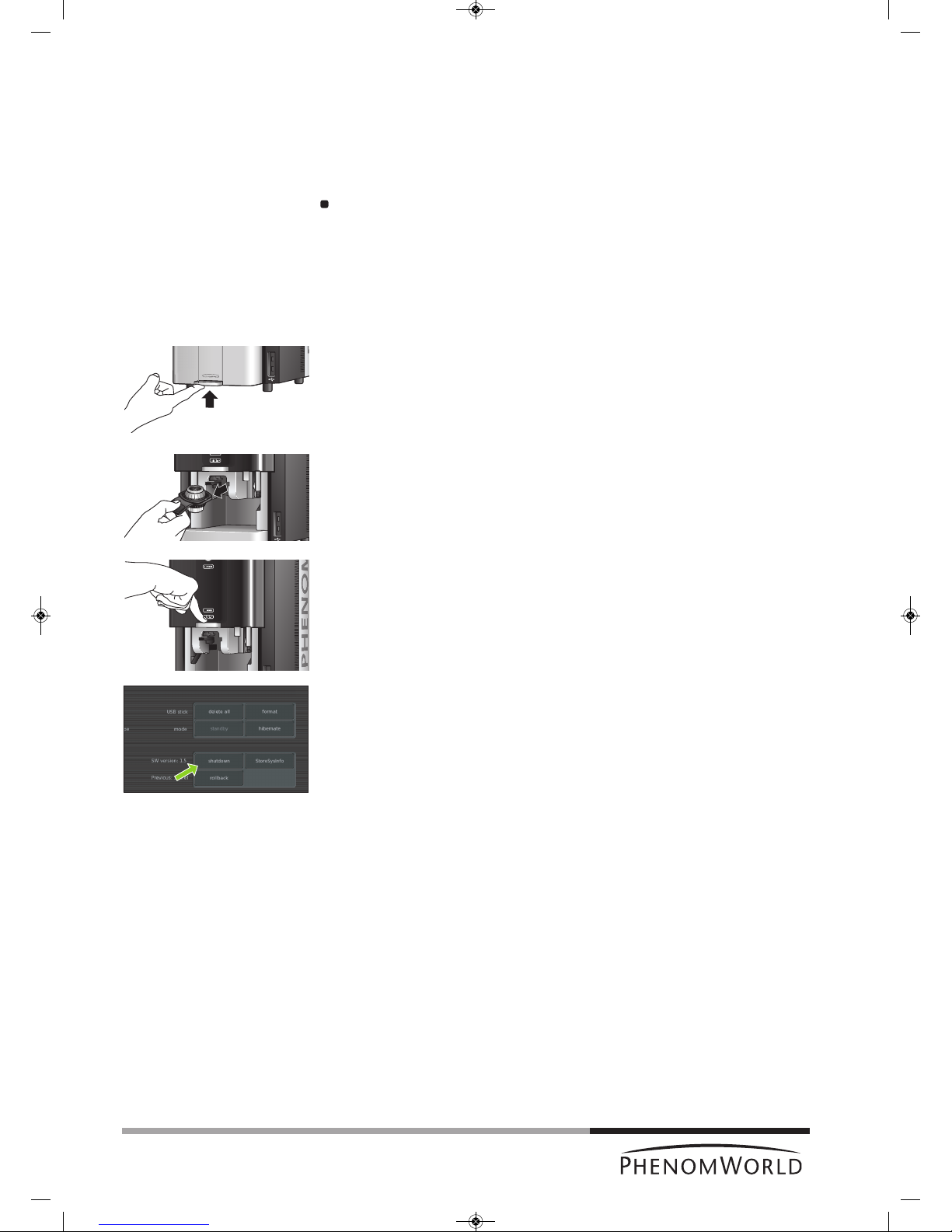
56
8. Preparing the Phenom for transport
Follow the below procedure in case the Phenom needs to be sent back for maintenance or
repair or if the rental period has ended.
8.1 Return procedure
R
eturn the Phenom in the wooden crate in which it arrived.
If you do not have the original Phenom packaging anymore and/or need asistance in
arranging transport contact Phenom-World’s Customer Support.
8.2 Prepare for packing
The following procedure can also be found on the packaging instructions inside the flight case.
1 Unload the sample container. For this, refer to chapter 4.9 ‘Unloading the sample’.
2 Close the door.
3 Touch Shutdown to prepare the Phenom for complete switch off. For this, refer to
chapter 5.7.2 ‘Shutdown’.
> The Phenom now starts preparing for complete switch off. This will take
approximately 40 minutes.
> A timer on the Image screen counts down the time.
> After approximately 40 minutes the message ‘It is now safe to turn of your system’.
4 Now you can set the 0 / I switch on the power supply to 0 and safely disconnect all
system components.
PW_Phenom_Pro_X_Pro_Pure_Print:PW_Phenom_G2_Pro_G2_Pure 19-11-13 20:55 Pagina 56
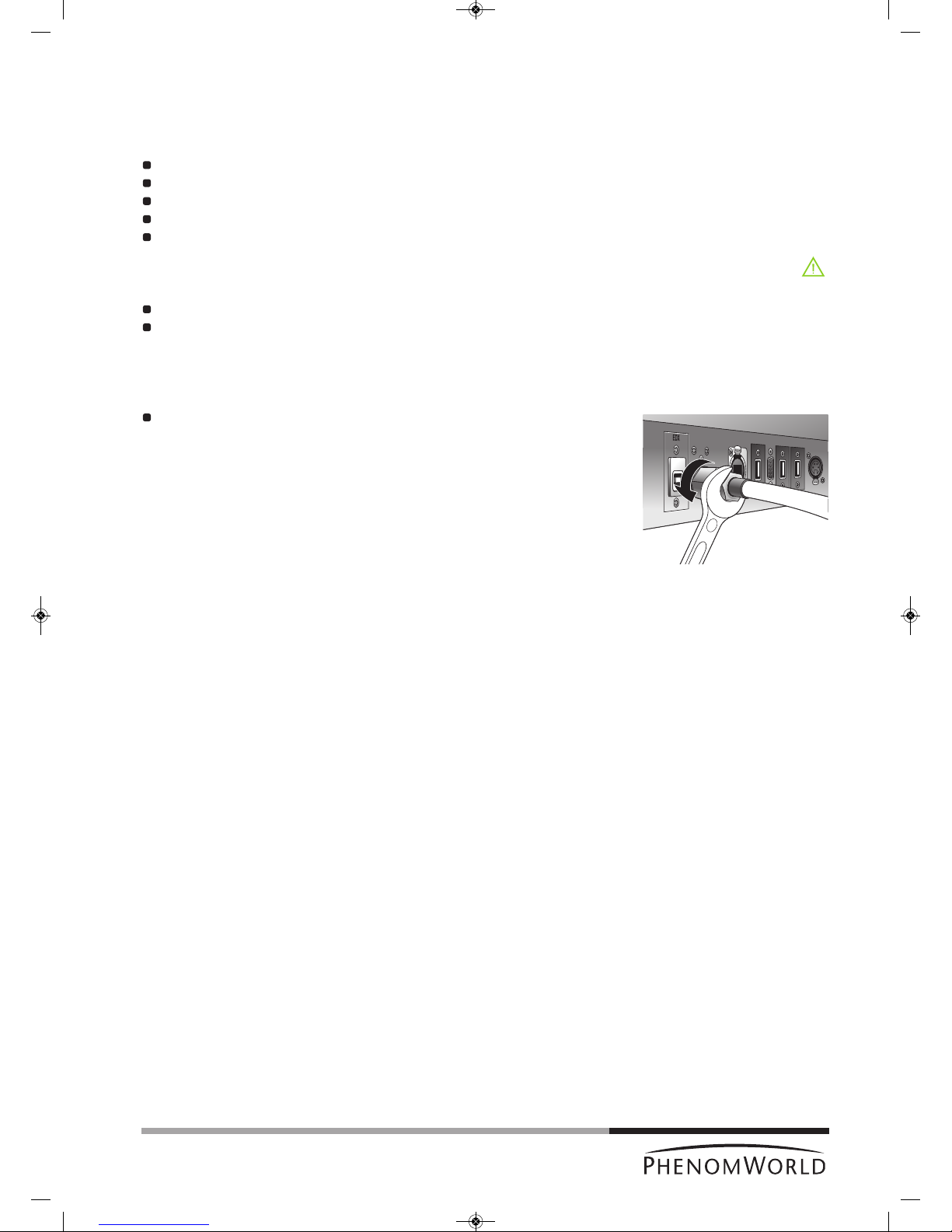
57
Caution!
Note!
1
4
8.3 Disconnecting and packing
The following procedure can also be found on the packaging instructions inside the flight case.
Tools/Materials needed for de-installation
14 mm (0.51") or adjustable spanner (wrench);
plastic packaging bag;
Phenom flight case;
Tip N Tell indicators;
shock watch indicators.
Hazard Warnings
The following hazard(s) are associated with these operations:
Heavy Lifting (2 persons required);
D
o not perform any of these operations without proper safety training specific to the
hazard(s).
1 Disconnect all cables from the back of the Phenom. This includes the monitor VGA
cable, the USB cable, both power cables, and the pre-vacuum pumphose.
Loosen the nut at the end of the hose, using a 14 mm (0.51") spanner (wrench).
2 Place the plastic packaging bag over the top of the Phenom.
Gently lift the Phenom and slide the bag under the feet to ensure the Phenom is
sealed for the duration of the transportation process.
3 Using two people, one at each side, carefully lift the Phenom and place it in the flight
case.
4 Place the top of the flight case over the Phenom and engage the clamps on each side
of the case. There are four clamps.
5 Apply Tip N Tell and Shock Indicators to the outside of the flight case if current
indicators were tripped during transit.
6 Strap the flight case to a standard pallet to prevent any potential damage while the
Phenom is in transit.
If any additional items are to be returned as well, this will be specified by
Phenom-World BV.
PW_Phenom_Pro_X_Pro_Pure_Print:PW_Phenom_G2_Pro_G2_Pure 19-11-13 20:55 Pagina 57

58
System
Imaging Modes
Resolution
Illumination
Digital Image Detection
Image Format
Image Resolution Options
Data Storage
Sample Stage
Sample Size
Sample Loading Time
Dimensions & Weight
Room Temperature
Humidity
Power
Recommended Table Size
Maximum operation altitude
9. Technical specifications
Imaging module, 19" touch screen monitor (ProX / Pro), 17" touch screen monitor
(Pure), Rotary knob, mouse (ProX / Pro), diaphragm vacuum pump, power supply,
USB flash drive.
L
ight Optical Magnification fixed: 20 - 120 x (ProX / Pro)
20 x, fixed (Pure)
Electron Optical: Magnification range: 80 – 100,000x, digital zoom: 12 x (ProX / Pro)
70 – 20,000x, digital zoom: 12 x (Pure)
17 nm (ProX /Pro)
30 nm (Pure)
Light Optical : Selectable axial and off-axis LEDs
Electron Optical: Long lifetime thermionic source (CeB6)
Light Optical Color CCD Camera
Electron Optical: High Sensitivity Backscatter Electron Detector (multi-mode)
JPEG, TIFF, BMP
456 x 456, 684 x 684, 1024 x 1024 and 2048 x 2048 pixels
USB 2.0 Flash drive
Computer controlled, motorized X and Y
Maximum sample dimensions up to 32 mm (Ø) or 100 mm(h)
Light Optical: < 5s
Electron Optical: < 30s
Imaging module: 286 mm / 11" (w) x 566 mm / 22" (d) x 495 mm / 19" (h),
50kg / 110 lbs
Diaphragm vacuum pump: 145 mm / 5.5" (w) x 220 / 8.5" (d) x 213 mm / 8" (h)
4.5kg / 9.9 lbs
Power supply: 156 mm / 6" (w) x 300 mm / 12" (h) x 74 mm / 3" (d), 3kg / 6.6 lbs
Monitor: 429 mm / 17" (w) x 379 mm / 15" (h) x 207 mm / 8" (d),
7.9 kg / 17.4 lbs (ProX / Pro)
355 mm / 14" (w) x 340 mm / 13" (h) x 203 mm / 8" (d),
3.2kg / 7 lbs (Pure)
15 °C ~ 30 °C (59 °F ~ 86 °F)
< 80% RH
Single phase AC 110 - 230Volt, 50/60Hz, 300W (max.)
120 cm / 47" x 75 cm / 9.5", load rating of 100 kg / 220 lbs
2000 m
PW_Phenom_Pro_X_Pro_Pure_Print:PW_Phenom_G2_Pro_G2_Pure 19-11-13 20:55 Pagina 58

59
GPL:
T
his device contains software which is covered by the GNU Public License. The source code for these portions
of the software is available on request.
ACE
[1] ACE(TM), [2]TAO(TM), [3]CIAO(TM), and [4]CoSMIC(TM) (henceforth referred to as “DOC software”) are
copyrighted by [5]Douglas C., Schmidt and his [6]research group at [7]Washington University, [8]University of
California, Irvine, and [9]Vanderbilt University, Copyright © 1993-2005, all rights reserved.
libtiff
Copyright © 1988-1997 Sam Leffler.
Copyright © 1991-1997 Silicon Graphics, Inc.
Permission to use, copy, modify, distribute, and sell the libtiff software and its documentation for any purpose is
hereby granted without fee.
libjpeg
© 1991-1998, Thomas G. Lane
We are required to state that “The Graphics Interchange Format © is the Copyright property of CompuServe
Incorporated. GIF(sm) is a Service Mark property of CompuServe Incorporated. “This software is based in part
on the work of the Independent JPEG Group”.
gSOAP
Part of the software embedded in this product is gSOAP software.
Portions created by gSOAP are Copyright © 2001-2004 Robert A. van Engelen, Genivia inc. All Rights
Reserved.
THE SOFTWARE IN THIS PRODUCT WAS IN PART PROVIDED BY GENIVIA INC AND ANY EXPRESS OR
IMPLIED WARRANTIES, INCLUDING, BUT NOT LIMITED TO, THE IMPLIED WARRANTIES OF
MERCHANTABILITY AND FITNESS FOR A PARTICULAR PURPOSE ARE DISCLAIMED. IN NO EVENT
SHALL THE AUTHOR BE LIABLE FOR ANY DIRECT, INDIRECT, INCIDENTAL, SPECIAL, EXEMPLARY, OR
CONSEQUENTIAL DAMAGES (INCLUDING, BUT NOT LIMITED TO, PROCUREMENT OF SUBSTITUTE
GOODS OR SERVICES; LOSS OF USE, DATA, OR PROFITS; OR BUSINESS INTERRUPTION) HOWEVER
CAUSED AND ON ANY THEORY OF LIABILITY, WHETHER IN CONTRACT, STRICT LIABILITY, OR TORT
(INCLUDING NEGLIGENCE OR OTHERWISE) ARISING IN ANY WAY OUT OF THE USE OF THIS
SOFTWARE, EVEN IF ADVISED OF THE POSSIBILITY OF SUCH DAMAGE.
FreeType:
Portions of this software are copyright © 2007 The FreeType Project (www.freetype.org). All rights reserved.
Anti-Grain Geometry Public License
Anti-Grain Geometry - Version 2.4
Copyright © 2002-2005 Maxim Shemanarev (McSeem)
Permission to copy, use, modify, sell and distribute this software is granted provided this copyright notice
appears in all copies.
This software is provided "as is" without express or implied warranty, and with no claim as to its suitability for
any purpose.
PW_Phenom_Pro_X_Pro_Pure_Print:PW_Phenom_G2_Pro_G2_Pure 19-11-13 20:55 Pagina 59

UM-092012-v1-2-PG3
Phenom-World BV, Dillenburgstraat 9E, 5652 AM Eindhoven, The Netherlands, www.phenom-world.com
©2013. Specifications and prices are subject to change without notice. All rights reserved. Reproduction, copying, usage,
modifying, hiring, renting, public performance, transmission and/or broadcasting in whole or in part is prohibited without the
written consent of Phenom-World BV. Find your Phenom-World contact information at www.phenom-world.com
PW_Phenom_Pro_X_Pro_Pure_Print:PW_Phenom_G2_Pro_G2_Pure 19-11-13 20:55 Pagina 60
 Loading...